WO2011126002A1 - におい放出システム、電子装置、物品、におい放出システムのにおい放出制御方法、プログラム、コンピュータ読み取り可能な記録媒体 - Google Patents
におい放出システム、電子装置、物品、におい放出システムのにおい放出制御方法、プログラム、コンピュータ読み取り可能な記録媒体 Download PDFInfo
- Publication number
- WO2011126002A1 WO2011126002A1 PCT/JP2011/058594 JP2011058594W WO2011126002A1 WO 2011126002 A1 WO2011126002 A1 WO 2011126002A1 JP 2011058594 W JP2011058594 W JP 2011058594W WO 2011126002 A1 WO2011126002 A1 WO 2011126002A1
- Authority
- WO
- WIPO (PCT)
- Prior art keywords
- odor
- moving
- moving object
- moving speed
- release
- Prior art date
- Legal status (The legal status is an assumption and is not a legal conclusion. Google has not performed a legal analysis and makes no representation as to the accuracy of the status listed.)
- Ceased
Links
Images






Classifications
-
- G—PHYSICS
- G09—EDUCATION; CRYPTOGRAPHY; DISPLAY; ADVERTISING; SEALS
- G09F—DISPLAYING; ADVERTISING; SIGNS; LABELS OR NAME-PLATES; SEALS
- G09F19/00—Advertising or display means not otherwise provided for
- G09F19/005—Scented advertising means
-
- A—HUMAN NECESSITIES
- A61—MEDICAL OR VETERINARY SCIENCE; HYGIENE
- A61L—METHODS OR APPARATUS FOR STERILISING MATERIALS OR OBJECTS IN GENERAL; DISINFECTION, STERILISATION OR DEODORISATION OF AIR; CHEMICAL ASPECTS OF BANDAGES, DRESSINGS, ABSORBENT PADS OR SURGICAL ARTICLES; MATERIALS FOR BANDAGES, DRESSINGS, ABSORBENT PADS OR SURGICAL ARTICLES
- A61L9/00—Disinfection, sterilisation or deodorisation of air
- A61L9/015—Disinfection, sterilisation or deodorisation of air using gaseous or vaporous substances, e.g. ozone
- A61L9/04—Disinfection, sterilisation or deodorisation of air using gaseous or vaporous substances, e.g. ozone using substances evaporated in the air without heating
- A61L9/12—Apparatus, e.g. holders, therefor
- A61L9/122—Apparatus, e.g. holders, therefor comprising a fan
-
- A—HUMAN NECESSITIES
- A61—MEDICAL OR VETERINARY SCIENCE; HYGIENE
- A61L—METHODS OR APPARATUS FOR STERILISING MATERIALS OR OBJECTS IN GENERAL; DISINFECTION, STERILISATION OR DEODORISATION OF AIR; CHEMICAL ASPECTS OF BANDAGES, DRESSINGS, ABSORBENT PADS OR SURGICAL ARTICLES; MATERIALS FOR BANDAGES, DRESSINGS, ABSORBENT PADS OR SURGICAL ARTICLES
- A61L2209/00—Aspects relating to disinfection, sterilisation or deodorisation of air
- A61L2209/10—Apparatus features
- A61L2209/11—Apparatus for controlling air treatment
- A61L2209/111—Sensor means, e.g. motion, brightness, scent, contaminant sensors
-
- A—HUMAN NECESSITIES
- A61—MEDICAL OR VETERINARY SCIENCE; HYGIENE
- A61L—METHODS OR APPARATUS FOR STERILISING MATERIALS OR OBJECTS IN GENERAL; DISINFECTION, STERILISATION OR DEODORISATION OF AIR; CHEMICAL ASPECTS OF BANDAGES, DRESSINGS, ABSORBENT PADS OR SURGICAL ARTICLES; MATERIALS FOR BANDAGES, DRESSINGS, ABSORBENT PADS OR SURGICAL ARTICLES
- A61L2209/00—Aspects relating to disinfection, sterilisation or deodorisation of air
- A61L2209/10—Apparatus features
- A61L2209/12—Lighting means
-
- A—HUMAN NECESSITIES
- A61—MEDICAL OR VETERINARY SCIENCE; HYGIENE
- A61L—METHODS OR APPARATUS FOR STERILISING MATERIALS OR OBJECTS IN GENERAL; DISINFECTION, STERILISATION OR DEODORISATION OF AIR; CHEMICAL ASPECTS OF BANDAGES, DRESSINGS, ABSORBENT PADS OR SURGICAL ARTICLES; MATERIALS FOR BANDAGES, DRESSINGS, ABSORBENT PADS OR SURGICAL ARTICLES
- A61L2209/00—Aspects relating to disinfection, sterilisation or deodorisation of air
- A61L2209/10—Apparatus features
- A61L2209/14—Filtering means
-
- G—PHYSICS
- G09—EDUCATION; CRYPTOGRAPHY; DISPLAY; ADVERTISING; SEALS
- G09F—DISPLAYING; ADVERTISING; SIGNS; LABELS OR NAME-PLATES; SEALS
- G09F27/00—Combined visual and audible advertising or displaying, e.g. for public address
- G09F2027/001—Comprising a presence or proximity detector
Definitions
- the present invention relates to a technology for emitting a scent by squeezing a target. More specifically, the present invention relates to a scent emission system, an electronic device, an article, and a scent emission system that squeezes a target from the moving speed of a moving object to release the scent. The present invention relates to a discharge control method, a program, and a computer-readable recording medium.
- Patent Documents 1 to 3 are known as techniques for releasing a smell by detecting the approach of a person.
- Patent Document 1 discloses a technique for detecting the approach of a human body with a human sensor and automatically generating a scent according to a plurality of types of art flowers.
- Patent Document 2 discloses a technique for discharging a scent in synchronization with the timing of inspiration
- Patent Document 3 discloses a technique for detecting a sound from a speaker or the like to generate a scent.
- any of these technologies senses the human body and emits an odor, and cannot emit an odor to a specific person.
- a housing having an odor source of odor components inside maintains and manages the environment inside the housing, such as temperature and humidity management inside the housing and maintenance of the concentration of gas components such as carbon dioxide (CO 2 ).
- CO 2 carbon dioxide
- the present invention has been made in view of the above problems, and an object of the present invention is to provide a technique capable of emitting a scent by narrowing down a target.
- an odor release system includes (1) an odor release device that is provided in a casing having an odor source inside and discharges odors from the casing to the outside; 2) a moving object detecting device that detects a moving object approaching the housing; (3) a moving speed calculating unit that calculates a moving speed of the moving object from a detection signal of the moving object detecting device; and a moving speed calculating unit. And a control device having a scent discharge control unit that releases scent by the scent discharge device when the moving speed of the moving body is lower than a preset speed.
- the odor release control method of the odor release system includes (1) an odor release device that is provided in a housing having an odor source inside and emits an odor from the housing to the outside, and (2) A scent discharge control method for a scent discharge system comprising a moving body detection device that detects a moving body approaching the housing, wherein the moving speed of the moving body is determined from a detection signal that detects the moving body approaching the housing.
- the odor is released to the outside from the odor emitting device only when the moving object to be released is divided into a moving object that is to be and a moving object that is not, and the moving object to be released is approaching the casing.
- a moving object having a low moving speed is referred to as “a person who is interested (in a casing having an odor source inside)” or “a person who has time”.
- a moving object having a high moving speed is regarded as a moving object (person) that is not the object of odor release, that is, for example, “a person who is not interested” or “a person who cannot afford time”.
- the odor component is not released unnecessarily to the moving object that is not the target for releasing the odor.
- a housing that has an odor source for odor components needs to maintain and manage the environment inside the housing (environmental conservation), such as temperature and humidity management inside the housing and maintenance of the concentration of gaseous components such as CO 2.
- environment conservation such as temperature and humidity management inside the housing and maintenance of the concentration of gaseous components such as CO 2.
- release of odor components and the maintenance / management of the environment inside the housing have a trade-off relationship.
- the odor itself is obtained directly by releasing the scent by narrowing down the target as described above, for example, improving the ability to attract customers, promoting the willingness to purchase, etc.
- the demerit caused by releasing the odor can be reduced.
- reducing the cost of maintaining and managing the environment inside the housing, such as the temperature and humidity inside the housing by releasing odors, or releasing gaseous components inside the housing, including odor components Various effects such as reduction of supply amount due to consumption due to consumption or avoidance / suppression of smoke damage due to odor being discharged as smoke can be obtained.
- an odor release system in (1) a housing for housing and cultivating a plant serving as an odor source, and the odor is emitted from the housing to the outside.
- An odor release device that releases odor
- (2) a concentration measurement device that measures the concentration of gas required for plant cultivation inside the housing and (3) a moving object detection that detects a moving object approaching the housing
- An apparatus (4) a moving speed calculating unit that calculates a moving speed of the moving object from a detection signal of the moving object detecting unit, and a value indicating a gas concentration measured by the concentration measuring device is greater than a preset value.
- a control device having an odor release control unit that causes the odor release device to release an odor when the moving speed of the moving body calculated by the moving speed calculation unit is equal to or lower than a preset speed.
- the odor release control method of the odor release system includes (1) an odor that is provided inside a housing that houses and cultivates plants serving as an odor source, and emits odors from the housing to the outside.
- a discharge device (2) a concentration measurement device that measures the concentration of gas required for plant cultivation inside the housing; and (3) a moving object detection device that detects a moving object approaching the housing.
- a method for controlling odor release of an odor release system comprising: a moving speed calculating step for calculating a moving speed of the moving object from a detection signal that detects a moving object approaching the casing; and cultivation of a plant inside the casing
- the odor emitting device Comprising a perfume releasing step of releasing Rinioi, the.
- the moving body approaching the housing is a target for releasing the odor.
- the odor is released to the outside from the odor emitting device only when the moving object that is the target of releasing the odor is divided into the moving object that is not and the moving object that is not, and approaches the casing.
- a moving object having a low moving speed is referred to as “a person who is interested (in a casing having an odor source inside)” or “a person who has time”.
- a moving object having a high moving speed is a moving object (person) that is not the object of odor release, that is, for example, "a person who is not interested (in a casing having an odor source inside)" or "a person who cannot afford time”. It is considered.
- the odor component is not released unnecessarily to the moving object that is not the target for releasing the odor.
- a housing that has an odor source for odor components needs to maintain and manage the environment inside the housing (environmental conservation), such as temperature and humidity management inside the housing and maintenance of the concentration of gaseous components such as CO 2.
- environment conservation such as temperature and humidity management inside the housing and maintenance of the concentration of gaseous components such as CO 2.
- release of odor components and the maintenance / management of the environment inside the housing have a trade-off relationship.
- the odor itself is obtained directly by releasing the scent by narrowing down the target as described above, for example, improving the ability to attract customers, promoting the willingness to purchase, etc.
- the demerit caused by releasing the odor can be reduced.
- reducing the cost of maintaining and managing the environment inside the housing, such as the temperature and humidity inside the housing by releasing odors, or releasing gaseous components inside the housing, including odor components Various effects such as a reduction in the amount of supply accompanying consumption due to consumption can be obtained.
- the maintenance of the concentration of the plant cultivation active ingredient is prioritized over the release of the odor,
- concentration of a cultivation active ingredient can be maintained in the state higher than the preset threshold value. Therefore, it becomes easier to maintain and manage the temperature and humidity in the plant cultivation warehouse and the concentration of the plant cultivation active ingredient.
- the electronic device according to the present invention is characterized by including the odor emission system according to the present invention.
- Examples of the electronic device include an artificial weather device.
- the article according to the present invention is characterized by including the odor release system according to the present invention.
- the electronic device or article includes the above-described odor emission system according to the present invention, so that the various effects described above can be obtained.
- the artificial meteorological apparatus supplies a gas component (plant cultivation active ingredient) required for plant cultivation into a plant cultivation warehouse, and grows and grows the plant by artificial lighting and appropriate temperature and humidity management.
- a gas component plant cultivation active ingredient
- it has a small cultivation area and plays a larger role as a demonstration device at exhibition venues such as supermarkets and shopping malls than the full-scale plant cultivation.
- the conventional artificial meteorological device is not provided with the odor emitting device as described above, and a demonstration relying on vision is performed.
- the odor source in the artificial meteorological device such as scents of plants that emit fragrances, such as firewood, is released to stimulate the sense of smell. Improvement is expected.
- the release of the odor filled in the artificial weather apparatus and the maintenance and management of the concentration and temperature / humidity of the plant cultivation active ingredient required for plant cultivation.
- the artificial weather device includes the odor emission system according to the present invention, thereby improving the ability to attract customers and the willingness to purchase due to the odor emission, and the casing.
- the consumption (supply amount) of the gas component (plant cultivation active ingredient) required for the cultivation of the plant inside the artificial meteorological apparatus main body can be reduced.
- the temperature and humidity in the housing and the concentration of the plant cultivation active ingredient can be maintained, and the plant cultivation environment can be kept good.
- each step of the odor release control method of the odor release system may be realized by a computer.
- a program for realizing the odor release control method of the odor release system in the computer also falls within the scope of the present invention.
- a computer-readable recording medium that records the program also falls within the scope of the present invention.
- the present invention by narrowing down the target for releasing the odor from the moving speed of the moving object, the odor is not discharged unnecessarily to the moving object that is not the target for releasing the odor.
- the environmental preservation inside the case such as the temperature and humidity inside the case, such as the temperature and humidity inside the case, and the odor can be obtained.
- Various effects such as reduction in costs caused by consumption of gas components inside the housing, including components, can be obtained.
- FIG. 1 It is a block diagram which shows the structure of the smell discharge
- FIG. 1 It is a schematic block diagram which shows the external appearance of the store which attached the smell discharge
- an artificial weather device will be described as an example of an electronic device provided with the odor emission system according to the present invention.
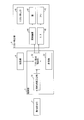
- FIG. 1 is a block diagram showing a configuration of an odor release system according to the present embodiment.
- FIG. 2 is a schematic configuration diagram showing the appearance of the artificial weather apparatus according to the present embodiment.
- the odor emission system includes a moving object detection unit 2 as a moving object detection device, a control unit 3 as a control device, and an odor emission unit 4 as an odor detection device.
- a moving object detection unit 2 as a moving object detection device
- a control unit 3 as a control device
- an odor emission unit 4 as an odor detection device.
- the configuration of each device (each unit) will be described later.
- an artificial weather device 100 according to the present embodiment is provided on an artificial weather device main body 1 (housing) serving as an electronic device main body according to the present embodiment.
- Each device (each part) is attached.
- the artificial weather device 100 includes an artificial weather device main body 1, a moving object detection unit 2, a control unit 3, and an odor emitting unit 4.
- each part (each device) of the artificial weather device 100 will be described.
- the artificial weather device main body 1 is a device that accommodates and cultivates a plant that becomes the odor source 110 inside.
- the artificial meteorological apparatus main body 1 conventionally known various artificial meteorological apparatuses are used. That is, the artificial weather device 100 has a configuration in which the moving object detection unit 2, the control unit 3, and the odor emitting unit 4 are attached to the general artificial weather device constituting the artificial weather device main body 1 as described above. Yes.
- the artificial meteorological apparatus contains a plant cultivation chamber (chamber), an air conditioner, a lighting device, oxygen (O 2 ), carbon dioxide (CO 2 ), water vapor, etc. necessary for plant cultivation for accommodating and cultivating plants. It is a device that is provided with a supply device that supplies the inside of a plant cultivation store, and that grows (nurtures) a plant by reproducing any complex environment by artificial lighting, appropriate temperature and humidity management, or the like.
- the artificial meteorological apparatus main body 1 is provided with these air conditioners, lighting devices, supply devices, and the like that are necessary for environmental conservation for cultivating plants.
- the artificial meteorological apparatus main body 1 is provided with an observation window for observing a plant that becomes an odor source 110, and a door (not shown) for planting, harvesting, and maintenance of the plant.
- the configuration of the artificial weather device itself that constitutes the artificial weather device main body 1 is the same as the conventional one. Therefore, detailed description of the configuration that the artificial weather apparatus main body 1 originally has is omitted here.
- the artificial meteorological apparatus main body 1 accommodates straw as a plant that becomes the odor source 110.
- the odor source 110 is not particularly limited as long as the odor can be sensed by smell.
- the moving body detection unit 2 includes a sensor or the like, is provided facing the outside of the artificial weather apparatus main body 1, and approaches a casing (the artificial meteorological apparatus main body 1 in the present embodiment) having an odor source 110 therein.
- the moving body 201 (moving body) is detected.
- the moving body detection unit 2 is preferably provided in or near the housing having the odor source 110 in order to detect the moving body 201 approaching the housing having the odor source 110 inside.
- the moving body detection part 2 is provided in the vicinity of the smell discharge port 41 provided in the artificial weather apparatus main body 1 as an example.
- the present embodiment is not limited to this.
- a Doppler sensor can be used as the sensor used in the moving object detection unit 2.
- the Doppler sensor is a sensor that utilizes the Doppler effect in which the frequency of the reflected wave changes depending on the speed of the moving body.
- the Doppler sensor is an oscillator that oscillates a microwave, a transmission antenna that transmits the microwave, a reception antenna that receives the reflected wave of the microwave reflected by the moving object, and outputs a mixer signal by mixing the received microwave
- a moving body detection (moving body movement detection) is performed by detecting the difference between the frequency of the transmitted microwave and the microwave reflected by the moving body using a mixer.
- the detection (observation) of the movement of the moving object 201 may be one-dimensional observation or two-dimensional observation according to the installation environment of the artificial weather apparatus 100.
- two-dimensional motion can be captured by simultaneously observing the moving body 201 (dual Doppler radar observation) using a plurality of Doppler sensors (Doppler radar) and analyzing the observation result.
- a Doppler sensor is used for the moving body detection unit 2, and the moving body 201 that approaches the casing having the odor source 110 inside from the moving speed of the moving body 201 detected by the Doppler sensor.
- the person (pedestrian) approaching the artificial weather apparatus main body 1 is detected.
- the odor emitting unit 4 is provided in a casing (in the present embodiment, the artificial meteorological apparatus main body 1) having an odor source 110 inside, and emits odors from the casing to the outside.
- the odor release unit 4 includes an odor release port 41, a lid 42 (open / close lid), a fan 43 (blower), an open / close mechanism 44, and a motor 45.
- the scent discharge port 41 is provided in the casing having the scent source 110 inside so as to face the outside, and allows the scent generated from the scent source 110 to be released to the moving body 201 approaching the casing. It is an opening.
- the odor discharge port 41 is provided with a lid 42 for opening and closing the odor discharge port 41 and a fan 43 for blowing air from the odor discharge port 41 to the outside of the casing.
- the lid 42 and the fan 43 are connected to an opening / closing mechanism 44 for driving the lid 42 to open and close and a motor 45 for rotating the fan 43, respectively.
- the opening / closing mechanism 44 and the motor 45 are driven and controlled by the control unit 3.
- the odor discharge port 41 is provided in the vicinity of the observation window of the artificial meteorological apparatus body 1, specifically, in the upper and lower two places near the center of the observation window is illustrated.
- the number, size, and arrangement of the odor discharge ports 41 may be set as appropriate in view of the size, cost, and the like of the artificial weather device main body 1 that is a housing, and are not particularly limited.
- control unit 3 calculates the moving speed of the moving body 201 from the detection signal of the moving body detecting unit 2, and controls the release of the odor from the odor emitting unit 4 using the calculated moving speed as a control factor.
- the calculation of the moving speed of the moving body 201 by the control unit 3 and the start of odor release by the odor emitting unit 4 are executed using the detection signal of the moving body detection unit 2 as a trigger.
- control unit 3 includes a movement speed calculation unit 31 (movement speed calculation unit), an odor release control unit 32 (odor emission unit), and a measurement unit 33 (measurement unit).
- the moving speed calculation unit 31 calculates the moving speed of the moving body 201 from the detection signal of the moving body detection unit 2.
- the moving speed of the moving body 201 can be calculated by measuring the change in wavelength using a Doppler sensor.
- the odor release control unit 32 controls the release of the odor from the odor release unit 4 by controlling the opening / closing mechanism 44 and the motor 45 in the odor release unit 4.
- the odor release control unit 32 compares the moving speed of the moving body 201 approaching the casing having the odor source 110 inside with a preset threshold value of the moving speed, and narrows down the moving body 201 that is a target for releasing the odor. Only when the moving body 201 (smell discharge target person) that is the target for releasing the smell approaches the casing, the smell discharge unit 4 releases the smell.
- the measuring unit 33 measures the time that has elapsed since the start of releasing the odor from the odor emitting unit 4.
- the odor release control unit 32 stops the odor release from the odor release unit 4 based on the measurement result by the measurement unit 33.
- the odor release control unit 32 releases the odor from the odor release unit 4 only when the moving body 201 (the odor release target person) to be released has approached the casing.
- the moving body 201 (smell discharge target person) that is the target of releasing the odor is the moving body 201 whose moving speed is equal to or lower than a preset speed (moving speed threshold).
- the odor release controller 32 opens the lid 42 and drives the fan 43 only when the moving speed of the moving body 201 calculated by the moving speed calculator 31 is equal to or lower than a preset speed. Thereby, the smell is released from the odor emitting unit 4 only when the moving speed of the moving body 201 calculated by the moving speed calculating unit 31 is equal to or lower than a preset speed.
- the threshold value for the moving speed is set based on the walking speed of the pedestrian.
- the target person of odor release is determined based on the walking speed of the visitor (pedestrian) in the installation environment of the artificial weather device 100 such as a supermarket, a shopping mall, an exhibition hall, etc., which is a demonstration venue. To do.
- the artificial meteorological apparatus used as the artificial meteorological apparatus body 1 supplies O 2 , CO 2 , water vapor, etc. necessary for plant cultivation into the plant cultivating cabinet, and provides artificial lighting and an appropriate temperature.
- the artificial meteorological apparatus body 1 supplies O 2 , CO 2 , water vapor, etc. necessary for plant cultivation into the plant cultivating cabinet, and provides artificial lighting and an appropriate temperature.
- it is a device that grows and grows plants by humidity management, etc., it has a small cultivation area and plays a larger role as a demonstration device at exhibition venues such as supermarkets and shopping malls than full-scale plant growth.
- the conventional artificial weather apparatus is not provided with the odor emitting part 4 as described above, and a demonstration relying on vision is performed.
- the ability to attract customers can be expected by stimulating the sense of smell by the release of fragrances, that is, fragrance components (dispersion, diffusion).
- fragrances that is, fragrance components (dispersion, diffusion).
- FIG. 2 when a fruit typified by persimmon is cultivated as shown in FIG. 2, the sweet smell (scent) of persimmon makes it possible to appeal to the sense of smell and the effect of the demonstration increases.
- fragrance filling the plant cultivator of the artificial meteorological device
- maintenance and management of the concentration and temperature and humidity of gaseous components such as CO 2 required for plant cultivation are in a trade-off relationship.
- an odor (odor) is unconditionally. Rather than releasing the odor of the source 110, the scent is released from the scent discharge port 41 only when the target person who releases the scent approaches by narrowing down the target person who releases the scent.
- the moving body 201 approaching the artificial weather apparatus 100 is The first group (people who are interested, people who can afford time), The second group (moving bodies (people) that do not belong to the first group, for example, people who are not interested, people who cannot afford time), It is classified as if it belongs to any of the above.
- the “person who is interested” in the present embodiment is, for example, “a person who is interested in the casing having the odor source 110 inside”, and more specifically, “who is interested in the demonstration by the artificial weather device 100”. It indicates "a person", but is not limited to this.
- the said classification is implemented by comparing the moving speed of the moving body 201 approaching the artificial weather apparatus 100 with the threshold value of the moving speed set beforehand as mentioned above.
- the threshold value of the moving speed is set based on the use speed of the moving object 201 that is the target of odor emission in the use of the electronic apparatus or the article according to the present invention on which the odor emission system is mounted and the installation environment. .
- the threshold value of the moving speed is set based on, for example, the walking speed of the visitor (pedestrian) at the demonstration venue of the artificial weather device 100.
- the threshold of the moving speed may be set as appropriate according to the installation environment of the artificial weather device 100 (for example, whether it is indoor passage, indoor, outdoor, or one-way), and is particularly limited. It is not a thing.
- the moving body 201 whose moving speed is equal to or lower than the threshold is classified into the first group, and the moving body 201 whose moving speed exceeds the threshold is classified into the second group.
- the moving body 201 (person) belonging to the first group is a odor release target and the moving speed of the moving body 201 approaching the artificial weather device 100 is equal to or lower than the threshold value, the inside of the plant cultivation box in the artificial weather device main body 1
- the smell of the odor source 110 is determined to belong to the second group (that is, the person who is not the object of odor release) when a sweet scent (aroma, smell) of candy is emitted from the odor discharge port 41 as the odor of the odor source 110 No odor emission from 41.
- the smell of the odor source 110 is released to persons belonging to the first group to improve the ability to attract customers, and the product related to the released odor, which is a product to be sold (this embodiment) If so, the desire to purchase the odor source 110 ( ⁇ itself) is promoted.
- the odor release from the odor release port 41 is not performed, and the loss of the plant cultivation active ingredient (for example, CO 2 ) in the plant cultivation warehouse is suppressed. At the same time, maintain the temperature and humidity in the plant cultivation cabinet to preserve the environment.
- a person approaching 100 may have a high moving speed.
- the present invention works particularly effectively for people who are interested but do not have a clear intention to purchase, who are lost, or who have time.
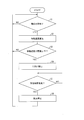
- FIG. 3 is a flowchart showing a flow of odor release processing by the odor release system according to the present embodiment.
- FIG. 4 is a diagram for explaining detection of the moving body 201 by the moving body detection unit 2.
- an area surrounded by a dotted line shows an example of an effective detection range of the moving object detection unit 2 when a Doppler sensor is used as the moving object detection unit 2.
- FIG. 4 shows an example in which the effective range of the moving object detection unit 2 is set to a range of 10 m and 90 degrees in front of the Doppler sensor.
- the effective detection range can be variously changed and is not limited to the above range.
- step S1 when the moving object detection unit 2 detects that the moving object 201 has approached the artificial weather device 100 (artificial weather device main body 1) (step S1), the moving speed calculation unit 31 determines from the signal received from the moving object detection unit 2. Then, the moving speed of the moving body 201 approaching the artificial weather device 100 is calculated (step S2).
- the odor release control unit 32 determines whether or not the moving speed of the moving body 201 calculated by the moving speed calculating unit 31 is equal to or less than a threshold value (step S3).
- the threshold value of the moving speed is 2 m / sec
- the odor release control unit 32 has a moving speed of the moving body 201 calculated by the moving speed calculating unit 31 as shown in FIG. 4 of 2 m / sec or less.
- the moving object 201 is regarded as an odor release target person, that is, a person belonging to the first group (“person who is interested” or “person who has time”).
- the odor release control unit 32 sends a signal for opening the lid 42 provided at the odor release port 41 to the opening / closing mechanism 44 and sends a signal for rotating the fan 43 to the motor 45. At the same time, the odor release control unit 32 sends a time measurement start signal to the measurement unit 33.
- the lid 42 is opened and the fan 43 is rotated to release the odor of the odor source 110 from the odor discharge port 41 to the outside (step S4).
- the odor release control unit 32 sends a signal for stopping the fan 43 to the motor 45 when the time measured by the measurement unit 33 has passed a preset time (scent release time, for example, 10 seconds) (step S5). At the same time, a signal for closing the lid 42 is sent to the opening / closing mechanism 44.
- step S6 the fan 43 is stopped and the lid 42 is closed to stop the discharge of the odor from the odor discharge port 41.
- the odor release control unit 32 determines in step S3 that the moving speed of the moving body 201 calculated by the moving speed calculating section 31 is faster than 2 m / sec as shown in FIG. It is considered that the subject is not a subject (that is, belongs to the second group), and the process moves to Step S1 for moving object detection again without releasing the odor of the odor source 110 to the outside.
- step S1 when the approach of the moving body 201 is not detected as indicated by the broken arrow in FIG. 4, the process does not proceed to step S2, but the moving body detection in step S1 is repeatedly performed.
- the present embodiment it is possible to improve the ability to attract customers and the willingness to purchase by releasing odors, and it is determined that the moving speed is relatively high, which is determined to be interested or have time.
- the consumption of the plant cultivation active ingredient in the plant cultivation warehouse such as CO 2 can be reduced.
- the target and releasing the odor as described above, it is possible to maintain the temperature and humidity in the plant cultivation cabinet and the concentration of the plant cultivation active ingredient, and to keep the plant cultivation environment favorable.
- the moving speed threshold (walking speed threshold) is set to 2 m / sec.
- the moving speed threshold can be set to an arbitrary speed.
- the odor release time (measurement time by the measurement unit 33) is 10 seconds, but the odor release time can also be set to an arbitrary time.
- a Doppler sensor is used for the moving object detection unit 2 and a person such as a pedestrian approaching the artificial weather apparatus main body 1 is detected from the moving speed of the moving object 201 detected by the Doppler sensor.
- the case has been described as an example.
- the present embodiment is not limited to this, and a moving body 201 that approaches the artificial weather apparatus main body 1 by using a human body detection sensor (human sensor) using a Doppler sensor as the moving body detection unit 2.
- a person approaching the artificial meteorological apparatus main body 1 is detected, and a person approaching the artificial meteorological apparatus main body 1 is detected based on the moving speed of the person belonging to the group (1) and the person belonging to the group (2). It may be divided into
- each device in the odor emission system may be wired communication or wireless communication.
- an artificial weather device has been described as an example of an electronic device provided with the odor emission system according to the present invention.
- the present embodiment is not limited to this.
- the above-described odor emission system can be incorporated into various electronic devices or articles for the purpose of squeezing and releasing the odor of the odor source.
- the artificial meteorological apparatus main body used for cultivation of plants is used as a housing for housing cocoons as plants that become odor sources.
- cocoons are stored and stored as odor sources.
- an odor may be released outside the casing from the casing in which the odor component of such food is confined as an odor source using the odor releasing system.
- the ability to attract customers can be improved by the smell, but the consumption of odorous components can be reduced by narrowing down the target to release the odor, rather than unconditionally releasing the odor when a person approaches. Cost reduction can be achieved.
- the odor component that is confined in the casing is changed to an odor component according to the product to be sold or handled, such as an aroma component used in aromatherapy or perfume, and such a casing.
- an odor component used in aromatherapy or perfume
- the consumption of odorous components can be reduced by not releasing odors to people who run by or who pass by bicycles or cars.
- the present embodiment is not limited to this.
- the odor of the odor source may be not “odor” (odor) but “odor” (odor).
- Each means (block) of the control unit 3 may be configured by hardware logic, or using a CPU (Central Processing Unit) or MPU (Micro Processing Unit) as follows. It may be realized by software. That is, each means of the control unit 3 may be executed by software by causing a computer to function as each of the above means using a program. Further, each step of the odor release process (odor release control method) by the odor release system may be executed by software by causing a computer to execute the above steps using a program.
- a CPU Central Processing Unit
- MPU Micro Processing Unit
- control unit 3 includes a CPU or MPU that executes instructions of a program that realizes each function (step), a ROM (Read Only Memory) that stores the program, and a RAM (Random that expands the program into an executable format) Access Memory) and a storage device (recording medium) such as a memory for storing the program and various data.
- An object of the present invention is to read a program code (execution format program, intermediate code program, source program) of a control program of each unit (each unit) of the control unit 3, which is software that realizes the functions (steps) described above, by a computer.
- This can also be achieved by supplying the recording medium recorded as possible to each unit of the control unit 3 and reading and executing the program code recorded on the recording medium by the computer (or CPU or MPU).
- the recording medium that supplies the program code to the control unit 3 is not limited to a specific structure or type. That is, the recording medium includes, for example, a tape system such as a magnetic tape and a cassette tape, a magnetic disk such as a floppy (registered trademark) disk / hard disk, and an optical disk such as a CD-ROM / MO / MD / DVD / CD-R.
- a disk system, a card system such as an IC card (including a memory card) / optical card, or a semiconductor memory system such as a mask ROM / EPROM / EEPROM / flash ROM can be used.
- the object of the present invention can be achieved even if the control unit 3 is configured to be connectable to a communication network.
- the program code is supplied to the control unit 3 via the communication network.
- the communication network is not limited to a specific type or form as long as it can supply the program code to the control unit 3.
- the Internet intranet, extranet, LAN, ISDN, VAN, CATV communication network, virtual private network (Virtual Private Network), telephone line network, mobile communication network, satellite communication network, etc. may be used.
- the transmission medium constituting the communication network may be any medium that can transmit the program code, and is not limited to a specific configuration or type.
- wired lines such as IEEE 1394, USB (Universal Serial Bus), power line carrier, cable TV line, telephone line, ADSL (Asymmetric Digital Subscriber Line), etc.
- infrared rays such as IrDA and remote control, Bluetooth (registered trademark), 802.11
- radio such as radio, HDR, mobile phone network, satellite line, terrestrial digital network.
- the present invention can also be realized in the form of a computer data signal embedded in a carrier wave in which the program code is embodied by electronic transmission.
- the preset time (odor release time) does not necessarily have to be constant.
- the moving object detection unit 2 when comparing the moving speeds between the moving objects 201 (persons) determined to be odor emitting persons, those who have a relatively slow moving speed have a relative moving speed. Compared to fast people, the time to smell the same concentration is shorter.
- FIG. 5 is a block diagram showing the configuration of the odor release system according to the present embodiment.
- the odor release system further includes a storage unit 5 as a storage device in addition to each device (each unit) shown in FIG. 1.
- the storage unit 5 stores (stores) an LUT (lookup table, conversion table) for changing the odor release time according to the moving speed of the moving body 201.
- LUT lookup table, conversion table
- the odor release time that is, the time from the start of odor release from the odor release unit 4 to the stop thereof is set to be longer as the moving speed of the moving body 201 calculated by the moving speed calculation unit 31 is slower.
- an interpolation calculation is performed from the previous and next movement times from the odor release time obtained by the LUT. Then, the odor release time may be determined, and a certain odor release time may be associated with a certain range of moving speed.
- a magnetic disk device such as an HDD or an EEPROM that is a semiconductor memory, which keeps data even when the power is turned off, is preferably used.
- the flow of the odor release processing by the odor release system in the present embodiment is basically the same as the flow shown in FIG. 3 in the first embodiment.
- the odor release control unit 32 determines whether or not the moving speed of the moving body 201 calculated by the moving speed calculating unit 31 is equal to or less than a threshold in step S3 in the flow shown in FIG.
- the odor release time associated with the moving speed of the moving object 201 calculated by the moving speed calculating unit 31 is determined with reference to the LUT stored in the storage unit 5.
- step S5 when the time measured by the measuring unit 33 has elapsed in advance based on the moving speed (step S5), a signal for stopping the fan 43 is sent to the motor 45 and the lid 42 is moved. A signal for closing is sent to the opening / closing mechanism 44.
- the odor release control unit 32 when the odor release control unit 32 stops releasing the odor from the odor release port 41 based on the measurement result by the measurement unit 33, the odor release control unit 32 starts to release the odor from the odor release port 41.
- the odor release time can be appropriately changed according to the moving speed of the moving body 201, the odor discharge target person whose movement speed is relatively high even for the odor discharge target person whose movement speed is relatively slow. Can give enough olfactory stimulation.
- the consumption of plant cultivation active ingredients such as CO 2 is reduced, and the environment in the warehouse is preserved. It is possible to give sufficient olfactory stimulation while trying.
- Embodiment 1 the case where a Doppler sensor is used as the moving body detection unit 2 has been described as an example.
- the sensor used in the moving object detection unit 2 is not particularly limited as long as it can detect the moving object 201, and a plurality or a plurality of types of sensors may be used in combination. I do not care.
- the moving object detection unit 2 Doppler sensor
- the moving body detection unit 2 can be removed from the artificial weather apparatus main body 1 and installed in an arbitrary place depending on the installation environment of the artificial weather apparatus main body 1, for example, the situation of a passage or a building.
- data communication between each device (each unit) in the odor emission system may be wired communication or wireless communication.
- FIG. 6 is a schematic configuration diagram showing an external appearance of the artificial weather device 100 according to the present embodiment.
- FIG. 7 is a diagram for explaining detection of a moving object by the moving object detection unit 2 shown in FIG.
- the artificial weather device 100 includes two sensors 21 and 22 provided as a moving object detection unit 2 spaced apart from each other by a certain distance.
- a human body detection sensor (human sensor) that detects the presence of a person by infrared rays, ultrasonic waves, visible light, or the like can be used, but is not particularly limited.
- the moving body 201 approaching the artificial weather apparatus 100 can be detected by disposing the moving body detection unit 2 in front of the installation location of the artificial weather apparatus 100 as shown in FIGS. it can.
- the sensors 21 and 22 are spaced apart by a certain distance (for example, 10 m).
- the moving speed calculation unit 31 calculates the moving time of the moving object 201 from the time passing between the sensors 21 and 22.
- the flow of the odor release processing by the odor release system in the present embodiment is basically the same as the flow shown in FIG. 3 in the first embodiment.
- step S1 when the sensors 21 and 22 detect that the moving body 201 approaches the artificial weather device 100 (artificial weather device main body 1) in step S1, the movement is performed in step S2.
- the speed calculation unit 31 calculates the moving speed of the moving body 201 approaching the artificial weather apparatus 100 from the signals received from the sensors 21 and 22.
- the moving speed of the moving body 201 can be easily calculated from the difference in detection time of the moving body 201 by the two sensors 21 and 22 arranged at a predetermined distance as described above.
- step S1 when the approach of the moving body 201 is not detected by the sensor 22 as indicated by the broken arrow in FIG. 7, the moving body detection in step S1 is repeatedly performed without moving to step S2.
- the moving object detection unit 2 As described above, it is possible to use a sensor other than the Doppler sensor as the moving object detection unit 2, and it can be detached from the artificial weather apparatus main body 1 and installed in an arbitrary place.
- the type of sensor used as the moving object detection unit 2 can be changed as appropriate from the installation environment and cost of the casing.
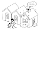
- FIG. 8 is a schematic configuration diagram showing an appearance of the store 11 to which the odor release system according to the present embodiment is attached.
- the store 11 functions as a casing having an odor source (not shown) inside.
- the store 11 is not particularly limited, but the odor release system according to the present embodiment is capable of attracting customers by, for example, releasing the smell of an odor source outside the store, such as a coffee shop or a yakitori restaurant. While improving, it is particularly effective in stores where smoke damage becomes a problem due to the smell being discharged as smoke outside the store.
- the odor (smoke) from the odor source is required to be discharged from an exhaust port 12 provided at a position away from the traffic as a countermeasure against smoke damage to the surrounding residents.
- the normal exhaust that is, the release of odor (smoke) from the odor source in the normal state is a position apart from the human traffic, apart from the odor emission port 41.
- a description will be given of a case where the odor is released from the odor discharge port 41 when the odor discharge target person approaches the store 11 only from the exhaust port 12 such as a chimney provided in the store.
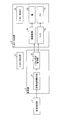
- FIG. 9 is a block diagram showing the configuration of the odor release system according to the present embodiment.
- the odor emission system includes a moving object detection unit 2 as a moving object detection device, a control unit 3 as a control device, an odor emission unit 4 as an odor detection device, and an odor measurement device.
- the odor measuring unit 6 is provided.
- a Doppler sensor is used for the moving object detection unit 2, and a person approaching the artificial weather apparatus main body 1 is detected from the moving speed of the moving object 201 detected by the Doppler sensor.
- the present embodiment is not limited to this.
- the moving object detection unit 2 and the odor emitting unit 4 are provided in the store 11 as in the present embodiment, the moving object detection unit 2 and the odor emitting unit 4 are provided so as to face people.
- the odor measuring unit 6 measures the strength of the odor emitted from the odor emitting unit 4 to the outside of the store 11 around the store 11.
- the odor measuring unit 6 can be a general odor measuring device such as an odor sensor.
- the type of odor measuring device is not particularly limited, and various known sensors that measure the odor intensity can be used.
- control unit 3 includes a moving speed calculation unit 31 and an odor release control unit 32.
- the calculation of the moving speed of the moving body 201 by the control unit 3 and the start of odor release by the odor emitting unit 4 are executed using the detection signal of the moving object detection unit 2 as a trigger, as in the first embodiment.
- the odor release stop by the odor release unit 4 is not based on the measurement of the odor release time by the measurement unit 33 as in the first embodiment, but based on the measurement result by the odor measurement unit 6.
- the odor release control unit 32 monitors a signal indicating the intensity of the odor sent from the odor measurement unit 6.
- the odor emission control unit 32 causes the odor emission unit 4 to emit an odor when a moving object 201 (an odor emission target person) that is an object of odor emission approaches the store 11 as a housing, and the odor measurement unit 6 performs measurement.
- the odor emission from the odor emission port 41 by the odor emission unit 4 is stopped.
- FIG. 10 is a flowchart showing a flow of odor release processing by the odor release system according to the present embodiment.
- step S11 smoke is exhausted from the exhaust port 12 of the store 11 (step S11).
- step S12 when the moving object detection unit 2 detects that the moving object 201 has approached the store 11 (step S12), the moving speed calculation unit 31 determines that the moving object that approaches the store 11 from the signal received from the moving object detection unit 2. The moving speed of 201 is calculated (step S13).
- the odor release control unit 32 determines whether or not the moving speed of the moving body 201 calculated by the moving speed calculating unit 31 is equal to or less than a threshold value (step S14).
- a threshold value of the moving speed is 2 m / sec
- the odor release control unit 32 has a moving speed of the moving body 201 calculated by the moving speed calculating unit 31 as shown in FIG. 4 of 2 m / sec or less.
- the moving object 201 is regarded as an odor release target person, that is, a person belonging to the first group (“person who is interested” or “person who has time”).
- the odor release control unit 32 sends a signal for opening the lid 42 provided at the odor release port 41 to the opening / closing mechanism 44 and sends a signal for rotating the fan 43 to the motor 45. At the same time, the odor release control unit 32 sends an odor measurement start signal to the odor measurement unit 6.
- the lid 42 is opened and the fan 43 is rotated to discharge the odor of the odor source 110 to the outside from the odor discharge port 41 (step S15).
- the odor release control unit 32 determines whether or not the value measured by the odor measurement unit 6 is equal to or less than a threshold value (step S16).
- a threshold value of the odor measurement value odor index in the odor measuring device
- the odor emission control unit 32 indicates that the odor is stronger as the measurement value is larger
- the odor release control unit 32 measures the measurement value obtained by the odor measurement unit 6. Is determined to be 500 or less, the process proceeds to step S15, and the odor emitting unit 4 is caused to emit odor from the odor emitting port 41.
- step S16 if the measured value by the odor measuring unit 6 is larger than 500 in step S16, a signal for stopping the fan 43 is sent to the motor 45 and a signal for closing the lid 42 is sent to the opening / closing mechanism 44.
- step S17 the fan 43 is stopped and the lid 42 is closed, and the discharge of the odor from the odor discharge port 41 is stopped.
- step S14 when the odor release control unit 32 determines in step S14 that the moving speed of the moving body 201 calculated by the moving speed calculating section 31 is faster than 2 m / sec as shown in FIG. It is considered that the person is not a subject (that is, belongs to the second group), and the process moves to step S12 for detecting a moving object again without releasing the smell in the store 11 from the smell discharge port 41 to the outside.
- step S12 If the approach of the moving object 201 is not detected in step S12, the moving object detection in step S13 is repeated without moving to step S13.
- the ability to attract customers can be improved by the release of odors, while the smell accompanied with smoke spreads around the store 11 or smoke is given up.
- the moving speed threshold (walking speed threshold) is 2 m / sec as in the first embodiment, but the moving speed threshold can be set to an arbitrary speed.
- the threshold value of the measured value by the odor measuring unit 6 can be set to an arbitrary value.
- the measured value by the odor measuring unit 6 is the odor index in the odor measuring device, but the present embodiment is not limited to this.
- the measurement value by the odor measuring unit 6 can be set to various values according to the type of odor measuring device used for the odor measuring unit 6 such as a voltage value indicating the concentration of odor or the intensity of odor.
- the moving object detection unit 2 detects the approach of the moving object 201 to the store 11.
- a plurality of or a plurality of types of sensors may be used in combination.
- what kind of sensor is used as the moving body detection unit 2 can be changed as appropriate from the installation environment and cost of the casing.
- the moving object detection unit 2 for example, a video camera such as a surveillance camera can be used. In this case, for example, by performing image processing using software, the moving speed of the moving body 201 approaching the store 11 can be calculated.
- the perfume undiluted solution for example, even if the odor has a certain level of strength, it may have a good odor, but if the odor is too strong, it may feel uncomfortable. In addition, there is a difference in the time until the odor is once diffused by the odor component. For this reason, by stopping the release of odor due to the strength of the odor, if the odor component is expensive, it is necessary to reduce the consumption of the odor component itself, or to maintain and manage the storage environment or cultivation environment of the odor source In such a case, it is possible to reduce the cost for such maintenance and management.
- an artificial weather device will be described as an example of an electronic device provided with the odor emission system according to the present invention.
- FIG. 11 is a schematic configuration diagram showing an appearance of the artificial weather device 100 according to the present embodiment.
- FIG. 12 is a block diagram showing the configuration of the odor release system according to the present embodiment.
- the odor release system includes a moving object detection unit 2 as a moving object detection device, a control unit 3 as a control device, an odor emission unit 4 as an odor detection device, and a concentration measurement device.
- Concentration measuring unit 7 and human body detecting unit 8 as a human body detecting device.
- the artificial weather device 100 according to the present embodiment has an odor according to the above-described present embodiment in the artificial weather device main body 1 (housing) serving as the electronic device main body according to the present embodiment.
- Each apparatus (parts) of the discharge system is attached.
- each part (each device) of the artificial weather device 100 will be described.
- the concentration measurement unit 7 measures the concentration of gas (gas component) required for cultivation of plants in the artificial meteorological apparatus main body 1, specifically, in the plant cultivation box in the artificial meteorological apparatus main body 1.
- CO 2 , O 2 , water vapor, etc. are mentioned as gas required for cultivation of the plant in a plant cultivation warehouse. These gases may be supplied alone or in some cases as a mixed gas.
- the concentration measuring device used in the concentration measuring unit 7 is not particularly limited as long as it can measure the concentration of the gas to be measured.
- An odor sensor can be used as the concentration measuring device.
- the concentration measuring unit 7 is a CO 2 sensor and measures the CO 2 concentration in the plant cultivation box will be described as an example, but the present embodiment is limited to this. It is not a thing.
- the human body detection unit 8 includes a sensor or the like, and detects the presence or absence of a person near the human body detection unit 8.
- a human body detection sensor human sensor
- the sensor is not particularly limited as long as it can detect the presence or absence of a nearby person, and a plurality of or a plurality of types of sensors may be used in combination.
- control unit 3 includes a moving speed calculation unit 31 and an odor release control unit 32.
- control unit 3 calculates the moving speed of the moving body 201 from the detection signal of the moving body detecting unit 2, and releases the odor using the calculated moving speed and the measurement result by the concentration measuring unit 7 as control factors. Controls the release of odor from part 4.
- the odor release control unit 32 monitors a signal sent from the concentration measurement unit 7 and indicating the concentration of the gas component to be measured.
- the odor release control unit 32 is a gas concentration measured by the concentration measurement unit 7 when a moving body 201 (smell discharge target person) that is a target for releasing odor approaches the artificial weather apparatus main body 1 that is a casing. Is greater than a preset threshold value and the moving speed of the moving body 201 calculated by the moving speed calculating section 31 is equal to or lower than a preset speed, the odor emitting section 4 releases the odor.
- the odor release control unit 32 determines whether the value indicating the gas concentration measured by the concentration measurement unit 7 is equal to or less than a preset threshold value or the moving speed of the moving body 201 calculated by the moving speed calculation unit 31. When the speed is higher than a preset speed, the scent discharger 4 does not release the scent. When the value indicating the gas concentration measured by the concentration measuring unit 7 falls below a preset threshold after the start of the odor emission by the odor emitting unit 4, the odor emission is stopped and the odor is released. Do not do.
- the odor release control unit 32 starts the discharge of the odor by the odor release unit 4 and then, as described above, the value indicating the gas concentration measured by the concentration measurement unit 7 falls below a preset threshold value. Alternatively, when it is determined from the detection signal of the human body detection unit 8 that there is no person around the artificial weather device 100, the emission of odor is stopped.
- FIG. 13 is a flowchart showing a flow of odor release processing by the odor release system according to the present embodiment.
- the moving speed calculation unit 31 determines from the signal received from the moving object detection unit 2. Then, the moving speed of the moving body 201 approaching the artificial weather device 100 is calculated (step S22).
- the odor release control unit 32 determines whether or not the moving speed of the moving body 201 calculated by the moving speed calculating unit 31 is equal to or less than a threshold value (step S23).
- the threshold value of the moving speed is 2 m / sec
- the odor release control unit 32 determines that the moving speed of the moving body 201 calculated by the moving speed calculating unit 31 is 2 m / sec or less.
- the person who is the subject of odor release that is, the person who belongs to the first group ("person who is interested" or "person who has time”).
- the odor release control unit 32 determines whether or not the gas concentration measured by the concentration measurement unit 7 is equal to or less than a threshold value (step S24).
- a threshold value is 800 ppm
- the odor release control unit 32 determines that the measurement value by the concentration measurement unit 7 is greater than 800 ppm, and a signal for opening the lid 42 provided in the odor discharge port 41. Is sent to the opening / closing mechanism 44 and a signal for rotating the fan 43 is sent to the motor 45.
- the lid 42 is opened and the fan 43 is rotated to discharge the odor of the odor source 110 to the outside from the odor discharge port 41 (step S25).
- the odor release control unit 32 determines whether or not the presence of a person is detected within the effective detection range (for example, within 3 m around the artificial weather device 100) by the human body detection unit 8 (step S26). Here, if presence of a person is detected, it will transfer to step S24 again and it will be determined whether gas concentration is larger than a threshold value. Note that the measurement of the gas concentration by the concentration measuring unit 7 is continuously performed even during the release of the odor by the odor emitting unit 4.
- the odor release control unit 32 sends a signal for stopping the fan 43 to the motor 45 and sends a signal for closing the lid 42 to the opening / closing mechanism 44. send.
- step S24 when it is determined that the measurement value by the concentration measurement unit 7 is not greater than the threshold value, that is, not greater than the threshold value, the odor release control unit 32 determines that the moving speed of the moving object 201 is equal to or less than the threshold value. Even if a human being is detected by the human body detection unit 8 and there is a person in the vicinity, the odor release unit 4 does not release the scent but releases the scent.
- the odor release control unit 32 sends a signal for stopping the fan 43 to the motor 45 when it is determined in step S24 that the measurement value by the concentration measurement unit 7 is not more than the threshold value, that is, not larger than the threshold value. And a signal for closing the lid 42 is sent to the opening / closing mechanism 44.
- step S27 the fan 43 is stopped and the lid 42 is closed, and the discharge of the odor from the odor discharge port 41 by the odor discharge section 4 is stopped.
- step S24 when the odor release control unit 32 determines that the moving speed of the moving body 201 calculated by the moving speed calculation section 31 is faster than 2 m / sec, the odor releasing control section 32 is not a person who is the object of odor discharge (ie, And the process moves to Step S1 for moving object detection again without releasing the odor in the store 11 from the odor discharge port 41 to the outside.
- step S21 If the approach of the moving body 201 is not detected in step S21, the moving body detection in step S11 is repeatedly performed without proceeding to step S22.
- the present embodiment it is possible to improve the ability to attract customers and the willingness to purchase by releasing odors, and it is determined that the moving speed is relatively high, which is determined to be interested or have time.
- the target By squeezing the target to a slow person and releasing the scent, the consumption of CO 2 and other gas components (plant cultivation active ingredients) required for cultivation of plants in the plant cultivation warehouse can be reduced.
- the target and releasing the odor as described above, it is possible to maintain the temperature and humidity in the plant cultivation cabinet and the concentration of the plant cultivation active ingredient, and to keep the plant cultivation environment favorable. In addition, it becomes easy to maintain and manage the temperature and humidity in the plant cultivation warehouse and the concentration of the plant cultivation active ingredient.
- the maintenance of the concentration of the plant cultivation active ingredient is prioritized over the release of the odor, thereby making the plant cultivation effective.
- the concentration of the component can be maintained in a state higher than a preset threshold value. Therefore, it becomes easier to maintain and manage the temperature and humidity in the plant cultivation warehouse and the concentration of the plant cultivation active ingredient.
- the moving speed threshold (walking speed threshold) is 2 m / sec as in the first embodiment, but the moving speed threshold can be set to an arbitrary speed.
- the threshold value of the measurement value by the concentration measurement unit 7 and the detection range by the human body detection unit 8 can be set to arbitrary values.
- the scent discharge system includes (1) a scent discharge device that is provided in a casing having an odor source inside and discharges scent from the casing to the outside, and (2) the casing described above.
- a moving object detecting device that detects a moving object approaching the body, (3) a moving speed calculating unit that calculates a moving speed of the moving object from a detection signal of the moving object detecting device, and a movement of the moving object calculated by the moving speed calculating unit.
- a control device having an odor release control unit for releasing odor by the odor release device when the speed is lower than a preset speed.
- the odor release control method of the odor release system includes (1) an odor release device that is provided in a housing having an odor source inside and emits an odor from the housing to the outside, and (2) A scent discharge control method for a scent discharge system comprising a moving body detection device that detects a moving body approaching the housing, wherein the moving speed of the moving body is determined from a detection signal that detects the moving body approaching the housing.
- the above-described odor release system narrows down the target for releasing odor from the moving speed of moving objects. In this way, by narrowing down the target and releasing the scent, it is possible to directly enjoy the merits of the scent itself, such as improving the ability to attract customers and promoting purchase motivation, which can be obtained directly by releasing the scent. On the other hand, as described above, it is possible to reduce the demerit caused by releasing the odor.
- the odor emission device is provided facing the outside of the casing, and an odor emission port for releasing the odor generated from the odor source to a moving object approaching the casing.
- an open / close lid that opens and closes the odor release port, and the odor release control unit opens the open / close lid when the moving speed of the moving object calculated by the moving speed calculating section is equal to or lower than a preset speed.
- the opening / closing lid is preferably closed when the moving speed of the moving object calculated by the moving speed calculator is higher than a preset speed.
- the scent discharge device includes a blower that is driven and controlled by the scent discharge control unit and blows air from the scent discharge port toward the outside of the housing. It is preferable to open the opening / closing lid and drive the blower only when the moving speed of the moving object calculated by the speed calculation unit is equal to or lower than a preset speed.
- the odor emission system further includes an odor measurement device that measures the intensity of the odor emitted to the outside of the casing by the odor emission device, and the odor emission control unit includes the odor measured by the odor measurement device.
- the value indicating the intensity of the odor is larger than a preset value, it is preferable to stop the odor emission by the odor emission device.
- control device further includes a measurement unit that measures a time elapsed since the start of the discharge of the odor by the odor release device, and the odor release control unit has a predetermined time elapsed by the time measured by the measurement unit. It is preferable to stop the odor release by the odor release device.
- the odor release by the odor release device is stopped, so that a wasteful odor is generated. Release can be suppressed. As a result, the various effects described above can be obtained.
- the control device further includes a measurement unit that measures a time elapsed since the start of odor release by the odor release device, and the odor release control unit is configured to release the odor based on a measurement result by the measurement unit. It is preferable to stop the discharge of odor by the device and to increase the time from the start of discharge of the odor by the odor release device to the stop as the moving speed of the moving object calculated by the moving speed calculation unit is slower. .
- the odor release time can be appropriately changed according to the moving speed of the moving object, so that the moving speed is relatively slow and the moving speed is relatively fast even for the moving object of the odor emitting object. Stimulate the olfactory sensation as much as the subject's moving body.
- it is not necessary to set the odor release time based on the moving object of the odor release target, which is relatively slow in moving speed, while reducing the consumption of gas components inside the case and preserving the environment inside the case Can give enough olfactory stimulation.
- the odor release system is (1) provided in a casing that accommodates and cultivates a plant that is a source of odor, and the casing.
- An odor releasing device for releasing odors from the outside (2) a concentration measuring device for measuring the concentration of gas required for cultivation of plants inside the housing, and (3) a moving object approaching the housing (4) a moving speed calculation unit for calculating the moving speed of the moving body from the detection signal of the moving body detection unit, and a value indicating the concentration of the gas measured by the concentration measuring device are set in advance.
- a control device having an odor release control unit that releases the odor by the odor release device when the moving speed of the moving object calculated by the moving speed calculation unit is less than or equal to a preset speed. The Eteiru.
- the odor release control method of the odor release system includes (1) an odor that is provided inside a housing that houses and cultivates plants serving as an odor source, and emits odors from the housing to the outside.
- a discharge device (2) a concentration measurement device that measures the concentration of gas required for plant cultivation inside the housing; and (3) a moving object detection device that detects a moving object approaching the housing.
- a method for controlling odor release of an odor release system comprising: a moving speed calculating step for calculating a moving speed of the moving object from a detection signal that detects a moving object approaching the casing; and cultivation of a plant inside the casing
- the odor emitting device Comprising a perfume releasing step of releasing Rinioi, the.
- the above-described odor release system narrows down the target for releasing odor from the moving speed of moving objects. In this way, by narrowing down the target and releasing the scent, it is possible to directly enjoy the merits of the scent itself, such as improving the ability to attract customers and promoting purchase motivation, which can be obtained directly by releasing the scent.
- Various effects such as a reduction in the amount of supply accompanying consumption due to consumption can be obtained.
- the maintenance of the concentration of the plant cultivation active ingredient is prioritized over the release of the odor,
- concentration of a cultivation active ingredient can be maintained in the state higher than the preset threshold value. Therefore, it becomes easier to maintain and manage the temperature and humidity in the plant cultivation warehouse and the concentration of the plant cultivation active ingredient.
- an electronic device includes the odor emission system according to the present invention.
- An example of the electronic device is an artificial weather device.
- an article according to the present invention includes the above-described odor release system according to the present invention.
- the electronic device or article includes the above-described odor emission system according to the present invention, so that the various effects described above can be obtained.
- each step of the odor release control method of the odor release system may be realized by a computer.
- a program for realizing the odor release control method of the odor release system in the computer also falls within the scope of the present invention.
- a computer-readable recording medium that records the program also falls within the scope of the present invention.
- the present invention can be suitably used for various devices or articles that detect a moving object and emit an odor.
Landscapes
- Health & Medical Sciences (AREA)
- Theoretical Computer Science (AREA)
- Epidemiology (AREA)
- Physics & Mathematics (AREA)
- General Physics & Mathematics (AREA)
- Engineering & Computer Science (AREA)
- Business, Economics & Management (AREA)
- Accounting & Taxation (AREA)
- Marketing (AREA)
- Life Sciences & Earth Sciences (AREA)
- Animal Behavior & Ethology (AREA)
- General Health & Medical Sciences (AREA)
- Public Health (AREA)
- Veterinary Medicine (AREA)
- Disinfection, Sterilisation Or Deodorisation Of Air (AREA)
Abstract
におい放出システムは、内部ににおい源を有する筐体に設けられ、筐体から外部に、においを放出するにおい放出部(4)と、筐体に接近する動体を検知する動体検知部(2)と、制御部(3)と、を備えている。制御部(3)は、動体検知部(2)の検知信号から動体の移動速度を算出する移動速度算出部(31)と、移動速度算出部(31)により算出された動体の移動速度が予め設定した速度以下のときに、におい放出部(4)によりにおいを放出させるにおい放出制御部(32)とを有する。
Description
本発明は、ターゲットを絞ってにおいを放出させる技術に関するものであり、より詳しくは、動体の移動速度からターゲットを絞ってにおいを放出させる、におい放出システム、電子装置、物品、におい放出システムのにおい放出制御方法、プログラム、コンピュータ読み取り可能な記録媒体に関するものである。
従来から、人体を感知してにおいを放出させる商品の開発が行われている。人の接近を感知してにおいを放出させる技術としては、例えば、特許文献1~3に示す技術が知られている。
例えば、特許文献1には、人感センサにより人体の接近を検知して、複数のアートフラワーの種類に応じた香りを自動的に発生させる技術が開示されている。
また、特許文献2には、吸気のタイミングに同期させて香りを吐出する技術が、特許文献3には、スピーカ等からの音声を感知して香りを発生させる技術が開示されている。
しかしながら、これらの技術は、何れも、人体を感知してにおいを放出させるものであり、特定の人に対してにおいを放出させることはできない。
すなわち、従来の技術では、人体を検知した場合、どのような状況であろうと香りを発生させる。このため、におい成分が無駄に消費される場合がある。
また、におい成分のにおい源を内部に有する筐体が、筐体内部の温湿度管理や例えば二酸化炭素(CO2)等の気体成分の濃度維持等、筐体内部の環境の維持・管理(環境保全)を必要とする場合、におい成分の放出と筐体内部の環境の維持・管理とは、トレードオフの関係にある。
このため、においを常時放出させたり、人の接近を検知した場合に無条件でにおいを放出させたりすることは、保存環境の管理のためのエネルギーコストのアップにも繋がる。
本発明は、上記問題点に鑑みなされたものであり、その目的は、ターゲットを絞ってにおいを放出させることができる技術を提供することにある。
本発明にかかるにおい放出システムは、上記の課題を解決するために、(1)内部ににおい源を有する筐体に設けられ、上記筐体から外部に、においを放出するにおい放出装置と、(2)上記筐体に接近する動体を検知する動体検知装置と、(3)上記動体検知装置の検知信号から上記動体の移動速度を算出する移動速度算出部と、上記移動速度算出部により算出された動体の移動速度が予め設定した速度以下のときに、上記におい放出装置によりにおいを放出させるにおい放出制御部とを有する制御装置と、を備えていることを特徴としている。
また、本発明にかかるにおい放出システムのにおい放出制御方法は、(1)内部ににおい源を有する筐体に設けられ、上記筐体から外部に、においを放出するにおい放出装置と、(2)上記筐体に接近する動体を検知する動体検知装置と、を備えているにおい放出システムのにおい放出制御方法であって、上記筐体に接近する動体を検知した検知信号から上記動体の移動速度を算出する移動速度算出ステップと、上記移動速度算出ステップで算出した動体の移動速度が予め設定した速度以下のときに、上記におい放出装置によりにおいを放出させるにおい放出ステップと、を含むことを特徴としている。
上記の各構成によれば、内部ににおい源を有する筐体に接近する動体の移動速度が予め設定した速度以下であるか否かによって、上記筐体に接近する動体を、においを放出させる対象となる動体と、そうでない動体とに分け、においを放出させる対象となる動体が上記筐体に接近した場合にのみ、上記におい放出装置から外部に、においを放出させる。
つまり、例えば、におい放出対象が「人」である場合、移動速度が遅い動体を、「(内部ににおい源を有する筐体に)興味がある人」あるいは「時間的な余裕のある人」とみなす。また、移動速度が速い動体を、におい放出対象ではない動体(人)、つまり、例えば、「興味がない人」、「時間的な余裕のない人」とみなす。
このように、本発明によれば、動体の移動速度からにおいを放出させるターゲットを絞ることで、においを放出させる対象でない動体に対し、無駄ににおい成分を放出させることがない。
特に、におい成分のにおい源を内部に有する筐体が、筐体内部の温湿度管理や例えばCO2等の気体成分の濃度維持等、筐体内部の環境の維持・管理(環境保全)を必要とする場合、におい成分の放出と筐体内部の環境の維持・管理とは、トレードオフの関係にある。
このため、本発明によれば、上記したようにターゲットを絞ってにおいを放出させることで、においを放出させることで直接的に得られる、例えば集客力の向上、購買意欲の促進等、においそのものによるメリットを享受することができる一方、においを放出させることで生じるデメリットを小さくすることができる。つまり、例えば、においを放出させることによる筐体内部の温湿度等、筐体内部の環境の維持・管理にかかる費用の削減、あるいは、におい成分も含めた、筐体内部の気体成分の、放出による消費に伴う供給量の削減、もしくは、においが煙として排出されることによる煙害の回避・抑制等の各種効果を得ることができる。
また、本発明にかかるにおい放出システムは、上記の課題を解決するために、(1)内部ににおい源となる植物を収容して栽培する筐体に設けられ、上記筐体から外部に、においを放出するにおい放出装置と、(2)上記筐体内部の植物の栽培に必要とされる気体の濃度を測定する濃度測定装置と、(3)上記筐体に接近する動体を検知する動体検知装置と、(4)上記動体検知部の検知信号から上記動体の移動速度を算出する移動速度算出部と、上記濃度測定装置により測定された気体の濃度を示す値が予め設定した値よりも大きく、かつ、上記移動速度算出部により算出された動体の移動速度が予め設定した速度以下のときに、上記におい放出装置によりにおいを放出させるにおい放出制御部とを有する制御装置と、を備えている。
また、本発明にかかるにおい放出システムのにおい放出制御方法は、(1)内部ににおい源となる植物を収容して栽培する筐体に設けられ、上記筐体から外部に、においを放出するにおい放出装置と、(2)上記筐体内部の植物の栽培に必要とされる気体の濃度を測定する濃度測定装置と、(3)上記筐体に接近する動体を検知する動体検知装置と、を備えているにおい放出システムのにおい放出制御方法であって、上記筐体に接近する動体を検知した検知信号から上記動体の移動速度を算出する移動速度算出ステップと、上記筐体内部の植物の栽培に必要とされる気体の濃度を示す値が予め設定した値よりも大きく、かつ、上記移動速度算出ステップで算出された動体の移動速度が予め設定した速度以下のときに、上記におい放出装置によりにおいを放出させるにおい放出ステップと、を含む。
上記の各構成においても、内部ににおい源を有する筐体に接近する動体の移動速度が予め設定した速度以下であるか否かによって、上記筐体に接近する動体を、においを放出させる対象となる動体と、そうでない動体とに分け、においを放出させる対象となる動体が上記筐体に接近した場合にのみ、上記におい放出装置から外部に、においを放出させる。
つまり、例えば、におい放出対象が「人」である場合、移動速度が遅い動体を、「(内部ににおい源を有する筐体に)興味がある人」あるいは「時間的な余裕のある人」とみなす。また、移動速度が速い動体を、におい放出対象ではない動体(人)、つまり、例えば、「(内部ににおい源を有する筐体に)興味がない人」、「時間的な余裕のない人」とみなす。
このように、本発明によれば、動体の移動速度からにおいを放出させるターゲットを絞ることで、においを放出させる対象でない動体に対し、無駄ににおい成分を放出させることがない。
特に、におい成分のにおい源を内部に有する筐体が、筐体内部の温湿度管理や例えばCO2等の気体成分の濃度維持等、筐体内部の環境の維持・管理(環境保全)を必要とする場合、におい成分の放出と筐体内部の環境の維持・管理とは、トレードオフの関係にある。
このため、本発明によれば、上記したようにターゲットを絞ってにおいを放出させることで、においを放出させることで直接的に得られる、例えば集客力の向上、購買意欲の促進等、においそのものによるメリットを享受することができる一方、においを放出させることで生じるデメリットを小さくすることができる。つまり、例えば、においを放出させることによる筐体内部の温湿度等、筐体内部の環境の維持・管理にかかる費用の削減、あるいは、におい成分も含めた、筐体内部の気体成分の、放出による消費に伴う供給量の削減等の各種効果を得ることができる。
しかも、上記の各構成によれば、においの放出による集客力および購買意欲の向上を図るとともに、興味がある、あるいは、時間的な余裕があると判断される、移動速度が比較的遅い人にターゲットを絞ってにおいを放出させることにより、CO2等の、筐体内部の植物の栽培に必要とされる気体成分(植物栽培有効成分)の濃度を一定に維持するために必要とされる該気体成分の供給量を削減することができる。また、上記したようにターゲットを絞ってにおいを放出させることで、筐体内の温湿度や植物栽培有効成分の濃度の維持を図ることができ、植物栽培環境を良好に保つことができる。また、筐体内の温湿度や植物栽培有効成分濃度の維持・管理が容易となる。
また、上記の各構成によれば、においの放出と植物栽培有効成分の濃度の維持とをはかりにかけたときに、においの放出よりも植物栽培有効成分の濃度の維持を優先させることで、植物栽培有効成分の濃度を、予め設定した閾値よりも高い状態で維持することができる。したがって、植物栽培庫内の温湿度や植物栽培有効成分濃度の維持・管理がより容易となる。
本発明にかかる電子装置は、本発明にかかるにおい放出システムを備えていることを特徴としている。
上記電子装置としては、例えば、人工気象装置が挙げられる。
また、本発明にかかる物品は、本発明にかかるにおい放出システムを備えていることを特徴としている。
上記の各構成によれば、上記電子装置あるいは物品が、上記した本発明にかかるにおい放出システムを備えていることで、上記した各種効果を得ることができる。
特に、人工気象装置は、植物栽培庫内に、植物の栽培に必要とされる気体成分(植物栽培有効成分)を供給し、人工照明と適切な温湿度管理等により植物を栽培し育成する装置であるが、栽培面積が小さく、本格的な植物の育成よりは、スーパーやショッピングモール等の展示会会場でのデモンストレーション用の装置としての役割が大きい。
しかしながら、従来の人工気象装置には上記したようなにおい放出装置は設けられておらず、視覚に頼ったデモンストレーションが行われている。
このようなデモンストレーションにおいては、視覚効果に加え、人工気象装置内のにおい源となる、例えば苺等の芳香を放つ植物のにおい(芳香成分)を放出させて嗅覚の刺激を行うことで、集客力の向上が見込める。しかしながら、人工気象装置内に充満するにおいの放出と、植物の栽培に必要とされる植物栽培有効成分の濃度および温湿度の維持・管理は、トレードオフの関係にある。
したがって、上記電子装置が人工気象装置である場合、該人工気象装置が本発明にかかる上記におい放出システムを備えていることで、においの放出による集客力および購買意欲の向上を図るとともに、筐体となる人工気象装置本体内部の植物の栽培に必要とされる気体成分(植物栽培有効成分)の消費量(供給量)を削減することができる。また、筐体内の温湿度や植物栽培有効成分の濃度の維持を図ることができ、植物栽培環境を良好に保つことができる。また、筐体内の温湿度や植物栽培有効成分濃度の維持・管理が容易となる。
なお、上記におい放出システムのにおい放出制御方法の各ステップは、コンピュータによって実現してもよい。この場合、コンピュータにプログラムに従って、上記におい放出システムのにおい放出制御方法の各ステップを実行させることができるので、上記におい放出システムのにおい放出制御方法をコンピュータにおいて実現するプログラムも本発明の範疇に入る。また、プログラムを記録したコンピュータ読み取り可能な記録媒体も本発明の範疇に入る。
以上のように、本発明によれば、動体の移動速度からにおいを放出させるターゲットを絞ることで、においを放出させる対象でない動体に対し、無駄ににおいを放出させることがない。
このため、においを放出させることで得られる、においそのものによる効果を得ることができる一方、においを放出させることで生じる、例えば、筐体内部の温湿度等、筐体内部の環境保全や、におい成分も含めた、筐体内部の気体成分の消費によって生じる費用を、削減することができる等の各種効果を得ることができる。
以下、本発明の実施の形態について、詳細に説明する。
〔実施の形態1〕
本発明の実施の一形態について図1~図4に基づいて説明すれば、以下の通りである。
本発明の実施の一形態について図1~図4に基づいて説明すれば、以下の通りである。
本実施の形態では、本発明にかかるにおい放出システムを備えた電子装置として、人工気象装置を例に挙げて説明する。
〈人工気象装置の概略構成〉
図1は、本実施の形態にかかるにおい放出システムの構成を示すブロック図である。また、図2は、本実施の形態にかかる人工気象装置の外観を示す概略構成図である。
図1は、本実施の形態にかかるにおい放出システムの構成を示すブロック図である。また、図2は、本実施の形態にかかる人工気象装置の外観を示す概略構成図である。
図1に示すように、本実施の形態にかかるにおい放出システムは、動体検知装置としての動体検知部2、制御装置としての制御部3、におい検出装置としてのにおい放出部4を備えている。なお、各装置(各部)の構成については、後で説明する。
図2に示すように、本実施の形態にかかる人工気象装置100は、本実施の形態にかかる電子装置本体となる人工気象装置本体1(筐体)に、本実施の形態にかかるにおい放出システムの各装置(各部)が取り付けられた構成を有している。
図2に示すように、上記人工気象装置100は、人工気象装置本体1、動体検知部2、制御部3、におい放出部4を備えている。
以下、人工気象装置100の各部(各装置)の構成について説明する。
〈人工気象装置本体1〉
人工気象装置本体1は、内部ににおい源110となる植物を収容して栽培する装置である。上記人工気象装置本体1としては、従来公知の各種人工気象装置が用いられる。すなわち、上記人工気象装置100は、人工気象装置本体1を構成する一般的な人工気象装置に、上記したように動体検知部2、制御部3、におい放出部4を取り付けた構成を有している。
人工気象装置本体1は、内部ににおい源110となる植物を収容して栽培する装置である。上記人工気象装置本体1としては、従来公知の各種人工気象装置が用いられる。すなわち、上記人工気象装置100は、人工気象装置本体1を構成する一般的な人工気象装置に、上記したように動体検知部2、制御部3、におい放出部4を取り付けた構成を有している。
人工気象装置は、植物を収容して栽培するための植物栽培庫(チャンバ)、空調装置、照明装置、植物の栽培に必要な酸素(O2)、二酸化炭素(CO2)、水蒸気等を上記植物栽培庫内に供給する供給装置を備え、人工照明や適切な温湿度管理等によりあらゆる複合環境を再現して植物の栽培(育成)を行う装置である。
人工気象装置本体1には、図示はしないが、植物を栽培するための環境保全に必要とされる、これら空調装置、照明装置、供給装置等が設けられている。
また、人工気象装置本体1には、におい源110となる植物の観察が可能な観察用の観察窓や、植物の植え付け・収穫・メンテナンス等を行うための図示しない扉が設けられている。
なお、上記したように人工気象装置本体1を構成する人工気象装置そのものの構成は従来と同じである。したがって、人工気象装置本体1が本来備えている構成の詳細な説明については、ここでは省略する。
本実施の形態では、図2に示すように、人工気象装置本体1に、におい源110となる植物として苺を収容した例を示している。しかしながら、上記におい源110としては、嗅覚によりにおいを感知することができるものであれば、特に限定されるものではない。
〈動体検知部2の構成〉
動体検知部2は、センサ等からなり、上記人工気象装置本体1の外部に面して設けられ、内部ににおい源110を有する筐体(本実施の形態では人工気象装置本体1)に接近する動体201(移動体)を検知する。
動体検知部2は、センサ等からなり、上記人工気象装置本体1の外部に面して設けられ、内部ににおい源110を有する筐体(本実施の形態では人工気象装置本体1)に接近する動体201(移動体)を検知する。
動体検知部2は、上記したように、内部ににおい源110を有する筐体に接近する動体201を検知するため、好適には、内部ににおい源110を有する筐体もしくはその近傍に設けられる。なお、図2では、一例として、動体検知部2が、人工気象装置本体1に設けられたにおい放出口41の近傍に設けられた場合を図示している。しかしながら、本実施の形態はこれに限定されるものではない。
上記動体検知部2に用いられるセンサとしては、例えばドップラーセンサ(ドップラーレーダ)を用いることができる。ドップラーセンサは、動体の速度により反射波の周波数が変わるドップラー効果を利用したセンサである。ドップラーセンサは、マイクロ波を発振する発振器、マイクロ波を送信するための送信アンテナ、動体で反射されたマイクロ波の反射波を受信する受信アンテナ、受信したマイクロ波をミキシングしてミキサ信号を出力するミキサ等を備え、送出したマイクロ波の周波数と動体で反射されたマイクロ波との差分をミキサで検出することによって動体検出(動体の移動検知)を行う。
なお、動体201の移動の検知(観測)は、人工気象装置100の設置環境に応じて、一次元的な観測を行ってもよく、二次元的な観測を行ってもよい。例えば、複数個のドップラーセンサ(ドップラーレーダ)を用いて同時に動体201の観測(デュアルドップラーレーダ観測)を行い、その観測結果を解析することで、二次元的な動きを捉えることができる。
本実施の形態では、上記したように、上記動体検知部2にドップラーセンサを使用し、該ドップラーセンサで検知した動体201の移動速度から、内部ににおい源110を有する筐体に接近する動体201として、人工気象装置本体1に接近する人(歩行者)を検知する。
〈におい放出部4の構成〉
ここで、制御部3について説明する前に、図1および図2を参照してにおい放出部4の構成について説明する。
ここで、制御部3について説明する前に、図1および図2を参照してにおい放出部4の構成について説明する。
におい放出部4は、内部ににおい源110を有する筐体(本実施の形態では人工気象装置本体1)に設けられ、筐体から外部に、においを放出させる。
図1に示すように、におい放出部4は、におい放出口41、蓋42(開閉蓋)、ファン43(送風機)、開閉機構44、モータ45を備えている。
におい放出口41は、内部ににおい源110を有する筐体に、外部に面して設けられ、上記におい源110から発生したにおいを、上記筐体に接近する動体201に対して放出させるための開口部である。
また、におい放出口41には、におい放出口41を開閉する蓋42と、におい放出口41から上記筐体の外部に向かって送風するファン43とが設けられている。
また、これら蓋42およびファン43には、蓋42を開閉駆動させる開閉機構44、ファン43を回転駆動させるモータ45が、それぞれ接続されている。これら開閉機構44およびモータ45は、制御部3によって駆動制御されている。
なお、図2では、一例として、におい放出口41を、人工気象装置本体1の観察窓の近傍、具体的には、観察窓の中央付近の上下2箇所に設けた場合について図示しているが、におい放出口41の数、大きさ、および配置は、筐体である人工気象装置本体1の大きさ、費用面等から、適宜設定すればよく、特に限定されるものではない。
〈制御部3の構成〉
制御部3は、動体検知部2の検知信号から動体201の移動速度を算出し、算出された移動速度を制御因子として、におい放出部4からのにおいの放出を制御する。
制御部3は、動体検知部2の検知信号から動体201の移動速度を算出し、算出された移動速度を制御因子として、におい放出部4からのにおいの放出を制御する。
制御部3による動体201の移動速度の算出およびにおい放出部4によるにおいの放出開始は、上記動体検知部2の検知信号をトリガとして実行される。
図1に示すように、制御部3は、移動速度算出部31(移動速度算出手段)、におい放出制御部32(におい放出手段)、計測部33(計測手段)を備えている。
移動速度算出部31は、上記動体検知部2の検知信号から上記動体201の移動速度を算出する。
上記したように動体検知部2にドップラーセンサ(ドップラーレーダ)を用いた場合、観測(検知)対象である動体201がドップラーセンサから遠ざかっている場合にはドップラー効果により反射波の波長が長くなり、逆に近づいている場合には反射波の波長が短くなる。本実施の形態では、ドップラーセンサによりこの波長の変化を測定することで、動体201の移動速度を算出することができる。
におい放出制御部32は、におい放出部4における開閉機構44およびモータ45を駆動制御することで、におい放出部4からのにおいの放出を制御する。
におい放出制御部32は、内部ににおい源110を有する筐体に接近する動体201の移動速度を、予め設定された移動速度の閾値と比較してにおいを放出させる対象となる動体201を絞る。そして、においを放出させる対象となる動体201(におい放出対象者)が上記筐体に接近したときにのみ、におい放出部4によりにおいを放出させる。
計測部33は、におい放出部4からにおいを放出開始してから経過した時間を計測する。におい放出制御部32は、上記計測部33による計測結果に基づいてにおい放出部4からのにおいの放出を停止させる。
〈におい放出制御部32による制御の概要〉
次に、におい放出制御部32による制御の概要について説明する。
次に、におい放出制御部32による制御の概要について説明する。
上記したように、におい放出制御部32は、においを放出させる対象となる動体201(におい放出対象者)が筐体に接近したときにのみ、におい放出部4からにおいを放出させる。ここで、においを放出させる対象となる動体201(におい放出対象者)とは、移動速度が、予め設定した速度(移動速度の閾値)以下の動体201である。
におい放出制御部32は、移動速度算出部31で算出された動体201の移動速度が、予め設定した速度以下のときにのみ、蓋42を開放してファン43を駆動させる。これにより、移動速度算出部31で算出された動体201の移動速度が予め設定した速度以下のときにのみ、におい放出部4からにおいを放出させる。
本実施の形態において、移動速度の閾値は、歩行者の歩行速度に基づいて設定される。本実施の形態では、デモンストレーション会場となる、スーパー、ショッピングモール、展示会会場等の、人工気象装置100の設置環境における見学者(歩行者)の歩行速度をもとに、におい放出対象者を決定する。
すなわち、人工気象装置本体1として用いられる人工気象装置は、前記したように、植物栽培庫内に、植物の栽培に必要なO2、CO2、水蒸気等を供給し、人工照明と適切な温湿度管理等により植物を栽培し育成する装置であるが、栽培面積が小さく、本格的な植物の育成よりは、スーパーやショッピングモール等の展示会会場でのデモンストレーション用の装置としての役割が大きい。
しかしながら、従来の人工気象装置には上記したようなにおい放出部4は設けられておらず、視覚に頼ったデモンストレーションが行われている。
このようなデモンストレーションにおいては、視覚効果に加え、香気、つまり、芳香成分の放出(散布、拡散)による嗅覚の刺激を行うことで、集客力の向上が見込める。図2に示すように植物として苺に代表される果物を栽培した場合、苺の甘い香り(匂い)により嗅覚への訴求が可能となり、デモンストレーションの効果が上がる。
しかしながら、人工気象装置の植物栽培庫内に充満する香気(匂い)の放出と、植物の栽培に必要とされるCO2等の気体成分(植物栽培有効成分)の濃度および温湿度の維持・管理は、トレードオフの関係にある。
このため、においとして、植物栽培庫内の植物の匂いを常時放出し続けたり、人工気象装置の近くに人が近づく度に植物栽培庫内の植物の匂いを放出させたりすることは、植物栽培環境の維持・管理の点から望ましくない。
また、人工気象装置の近くに人が近づく度に植物栽培庫内の植物の匂いを放出させることは、そのようなデモンストレーションに興味がない人や時間的に余裕のない人に対しても匂いを放出させることになるため、植物栽培庫内から放出された匂い成分(芳香成分)や植物栽培有効成分が無駄になる。また、植物栽培有効成分の消費量や温湿度管理のためのエネルギーコストのアップに繋がる。
このため、本実施の形態では、上記したように人工気象装置100に接近する動体201の移動速度を感知することで、人工気象装置100に動体201として人が接近したときには無条件で匂い(におい源110のにおい)を放出させるのではなく、匂いを放出させる対象者を絞ることで、匂いを放出させる対象者が接近したときにのみ、におい放出口41から匂いを放出させる。
本実施の形態では、人工気象装置100に接近する動体201の移動速度から、該人工気象装置100に接近する動体201を、
第1のグループ(興味がある人、時間的な余裕のある人)、
第2のグループ(第1のグループに属さない動体(人)、例えば興味がない人、時間的な余裕のない人)、
の何れかに属するとみなして分別する。なお、本実施の形態における「興味がある人」とは、例えば、「内部ににおい源110を有する筐体に興味がある人」、さらに言えば、「上記人工気象装置100によるデモンストレーションに興味がある人」を示すが、これに限定されるものではない。
第1のグループ(興味がある人、時間的な余裕のある人)、
第2のグループ(第1のグループに属さない動体(人)、例えば興味がない人、時間的な余裕のない人)、
の何れかに属するとみなして分別する。なお、本実施の形態における「興味がある人」とは、例えば、「内部ににおい源110を有する筐体に興味がある人」、さらに言えば、「上記人工気象装置100によるデモンストレーションに興味がある人」を示すが、これに限定されるものではない。
そして、上記分別は、人工気象装置100に接近する動体201の移動速度を、上述したように予め設定した移動速度の閾値と比較することで実施される。
なお、上記移動速度の閾値は、におい放出システムが搭載された本発明にかかる電子装置あるいは物品の用途や、その設置環境における、におい放出対象となる動体201の移動速度をもとに設定される。
本実施の形態であれば、上記移動速度の閾値は、例えば、人工気象装置100のデモンストレーション会場における見学者(歩行者)の歩行速度をもとに設定される。
つまり、上記移動速度の閾値は、例えば人工気象装置100の設置環境(例えば屋内通路、室内、屋外、あるいは一方通行であるか否か等)等に応じて適宜設定すればよく、特に限定されるものではない。
本実施の形態では、移動速度が上記閾値以下の動体201を第1のグループ、移動速度が上記閾値を越える動体201を第2のグループに分別する。
そして、第1のグループに属する動体201(人)をにおい放出対象者とし、人工気象装置100に接近する動体201の移動速度が上記閾値以下であるときには、人工気象装置本体1における植物栽培庫内のにおい源110のにおいとして、苺の甘い香り(香気、匂い)をにおい放出口41から放出し、第2のグループに属する(つまり、におい放出対象者ではない)と判断したときには、におい放出口41からのにおいの放出を行わない。
これにより、第1のグループの属する人に対してはにおい源110のにおいを放出させて、集客力を向上させるとともに、販売対象商品となる、放出されたにおいに関連した商品(本実施の形態であればにおい源110(苺)そのもの)の購買意欲の促進を図る。一方で、第2のグループの属する動体201(人)に対しては、におい放出口41からのにおいの放出を行わず、植物栽培庫内の植物栽培有効成分(例えばCO2)のロスを抑えるとともに植物栽培庫内の温湿度を維持し、庫内環境の保全を図る。
なお、はじめから上記人工気象装置100を用いたデモンストレーションによる販売対象商品を購買しようとして人工気象装置100に接近する人、あるいは、上記人工気象装置100を用いたデモンストレーションに強い関心を持って人工気象装置100に接近する人は、移動速度が速いこともあり得る。
しかしながら、そのような人は、もともと上記販売対象商品の購買を目的としていることから、においの放出に拘らず、上記人工気象装置100を目指して移動するし、もともと購買意欲も高い。
したがって、本発明は、興味はあるがはっきりとした購買の意思をもっていない人、迷っている人、時間に余裕がある人に、特に有効に作用する。
したがって、移動速度によってターゲットを絞ることは、非常に意義があるし、理に適っている。
〈におい放出システムによるにおい放出処理〉
次に、本実施の形態にかかるにおい放出システムによるにおい放出処理について説明する。
次に、本実施の形態にかかるにおい放出システムによるにおい放出処理について説明する。
図3は、本実施の形態にかかるにおい放出システムによるにおい放出処理の流れを示すフローチャートである。また、図4は、動体検知部2による動体201の検知を説明する図である。
図4中、点線で囲んだ領域は、動体検知部2としてドップラーセンサを用いたときの、動体検知部2の有効検知範囲の一例を示している。なお、図4では、動体検知部2の有効範囲を、ドップラーセンサの前方10m、90度の範囲とした場合を例に挙げて示している。しかしながら、有効検知範囲は、種々変更することが可能であり、上記範囲に限定されるものではない。
まず、動体検知部2が、人工気象装置100(人工気象装置本体1)に動体201が接近したことを検知すると(ステップS1)、移動速度算出部31は、動体検知部2から受け取った信号から、人工気象装置100に接近する動体201の移動速度を算出する(ステップS2)。
次に、におい放出制御部32は、移動速度算出部31によって算出された動体201の移動速度が閾値以下であるか否かを判定する(ステップS3)。ここで、上記移動速度の閾値を2m/secとすると、におい放出制御部32は、移動速度算出部31で算出された動体201の移動速度が図4に示すように2m/sec以下であると判定すると、動体201を、におい放出対象者、すなわち、第1のグループに属する人(「興味がある人」または「時間的に余裕がある人」)とみなす。そして、におい放出制御部32は、におい放出口41に設けられた蓋42を開放させるための信号を開閉機構44に送るとともに、ファン43を回転させるための信号をモータ45に送る。同時に、におい放出制御部32は、計測部33に、時間計測の開始信号を送る。
これにより、蓋42を開けてファン43を回転させて、におい放出口41から、におい源110のにおいを外部に放出する(ステップS4)。
上記におい放出制御部32は、計測部33による計測時間が、予め設定した時間(におい放出時間、例えば10秒)を経過すると(ステップS5)、ファン43を停止させるための信号をモータ45に送るとともに、蓋42を閉鎖させるための信号を開閉機構44に送る。
これにより、ファン43を停止させるとともに、蓋42を閉じて、におい放出口41からのにおいの放出を停止させる(ステップS6)。
一方、ステップS3で、におい放出制御部32は、移動速度算出部31で算出された動体201の移動速度が図4に示すように2m/secよりも速いと判定すると、動体201を、におい放出対象者ではない(すなわち、第2のグループに属する)とみなし、におい源110のにおいを外部に放出することなく、再び動体検知のためのステップS1に移行する。
また、ステップS1で、図4に折れ矢印で示すように動体201の接近が検知されなかった場合には、ステップS2に移行せず、ステップS1による動体検知が繰り返し行われる。
以上のように、本実施の形態によれば、においの放出による集客力および購買意欲の向上を図るとともに、興味がある、あるいは、時間的な余裕があると判断される、移動速度が比較的遅い人にターゲットを絞ってにおいを放出させることにより、CO2等の、植物栽培庫内の植物栽培有効成分の消費量を削減することができる。また、上記したようにターゲットを絞ってにおいを放出させることで、植物栽培庫内の温湿度や植物栽培有効成分濃度の維持を図ることができ、植物栽培環境を良好に保つことができる。また、植物栽培庫内の温湿度や植物栽培有効成分濃度の維持・管理が容易となる。
なお、上記説明においては、移動速度の閾値(歩行速度の閾値)を2m/secとしたが、前記したように、移動速度の閾値は、任意の速度に設定できる。
また、上記説明においては、においの放出時間(計測部33による計測時間)を10秒としたが、においの放出時間も任意の時間に設定できる。
〈変形例〉
なお、本実施の形態では、上記したように動体検知部2にドップラーセンサを使用し、ドップラーセンサで検知した動体201の移動速度から人工気象装置本体1に接近する歩行者等の人を検知する場合を例に挙げて説明した。
なお、本実施の形態では、上記したように動体検知部2にドップラーセンサを使用し、ドップラーセンサで検知した動体201の移動速度から人工気象装置本体1に接近する歩行者等の人を検知する場合を例に挙げて説明した。
しかしながら、本実施の形態はこれに限定されるものではなく、上記動体検知部2としてドップラーセンサを用いた人体検知センサ(人感センサ)を用いることにより、人工気象装置本体1に接近する動体201として、人工気象装置本体1に接近する人を検知し、その移動速度から、人工気象装置本体1に接近する人を、上記したようにグループ(1)に属する人とグループ(2)に属する人とに分けてもよい。
また、上記におい放出システムにおける各装置(各部)間のデータ通信は、有線による通信であってもよく、無線による通信であってもよい。
また、本実施の形態では、本発明にかかるにおい放出システムを備えた電子装置として、人工気象装置を例に挙げて説明した。しかしながら、本実施の形態はこれに限定されるものではない。
上記におい放出システムは、におい源のにおいを、ターゲットを絞って放出させることを目的とする各種電子装置あるいは物品に組み込むことが可能である。
すなわち、本実施の形態では、におい源となる植物として苺を収容する筐体として、植物の栽培に用いられる人工気象装置本体を使用したが、既に収穫された苺をにおい源として収容して保存する冷蔵保存庫を上記筐体として用いても構わない。この場合、ターゲットを絞ってにおい源のにおいを筐体外部に放出することで、集客力を向上させることができる一方で、冷蔵保存庫の冷却にかかる費用を削減することが可能となる。
また、例えばスーパー等の屋内での食品の販売コーナー等において、例えば販売対象として、焼鳥や鰻等、においが嗅覚を刺激する一方で、煙による実演販売が困難な食品に対し、実演販売ではなく、におい源としてそのような食品のにおい成分を閉じ込めた筐体から、上記におい放出システムを用いて筐体外部ににおいを放出させてもよい。
この場合、においにより集客力を向上させることができる一方で、人が接近したときには無条件でにおいを放出させるのではなく、においを放出させる対象者を絞ることで、におい成分の消費量をおさえ、コストダウンを図ることができる。
同様に、筐体内に閉じ込める、におい源となるにおい成分を、アロマセラピーや香水に用いられる芳香成分等、販売対象商品や取り扱い商品等に応じたにおいのにおい成分に変更し、そのような筐体を店舗の外やショーウィンドウ等に設置することで、店舗を締め切った状態でも商品のにおいを歩行者に嗅がせることができる。その一方で、走って通り過ぎる人や自転車あるいは自動車等で通りすぎる人に対してはにおいを放出しないことで、におい成分の消費量をおさえることができる。
また、本実施の形態では、においを放出させる対象が「人」であり、におい源110のにおいとして「匂い」(香気)を放出させる場合を例に挙げて説明した。しかしながら、本実施の形態はこれに限定されるものではない。
例えば、菜園、鳥等の飼育施設、花壇、車庫、食品貯蔵庫等に侵入したり近寄ったりしようとしている動物は、周囲の様子をうかがったり侵入経路を探したりすることで、移動速度が遅い傾向にある。このため、そのような習性を利用し、柵や囲いに、そのような動物が嫌うにおいを閉じ込めた筐体および本実施の形態にかかるにおい放出システムを取り付けることで、そのような動物による各種被害を防いだり、軽減したりすることができる。
すなわち、上記におい源のにおいは、「匂い」(香気)ではなく、「臭い」(臭気)であってもよい。
〈プログラム、コンピュータ読み取り可能な記録媒体〉
また、上記制御部3(制御装置)の各手段(ブロック)は、ハードウェアロジックによって構成してもよいし、次のように、CPU(Central Processing Unit)やMPU(Micro Processing Unit)を用いてソフトウェアによって実現してもよい。すなわち、上記制御部3の各手段は、プログラムを用いて、コンピュータを上記の各手段として機能させることで、ソフトウェアによって実行してもよい。また、上記におい放出システムによるにおい放出処理(におい放出制御方法)の各ステップは、プログラムを用いて、コンピュータに、上記の各ステップを実行させることで、ソフトウェアによって実行してもよい。
また、上記制御部3(制御装置)の各手段(ブロック)は、ハードウェアロジックによって構成してもよいし、次のように、CPU(Central Processing Unit)やMPU(Micro Processing Unit)を用いてソフトウェアによって実現してもよい。すなわち、上記制御部3の各手段は、プログラムを用いて、コンピュータを上記の各手段として機能させることで、ソフトウェアによって実行してもよい。また、上記におい放出システムによるにおい放出処理(におい放出制御方法)の各ステップは、プログラムを用いて、コンピュータに、上記の各ステップを実行させることで、ソフトウェアによって実行してもよい。
すなわち、制御部3は、各機能(ステップ)を実現するプログラムの命令を実行するCPUもしくはMPU、このプログラムを格納したROM(Read Only Memory)、上記プログラムを実行可能な形式に展開するRAM(Random Access Memory)、および、上記プログラムおよび各種データを格納するメモリ等の記憶装置(記録媒体)等を備えている。
本発明の目的は、上述した機能(ステップ)を実現するソフトウェアである、制御部3の各部(各手段)の制御プログラムのプログラムコード(実行形式プログラム、中間コードプログラム、ソースプログラム)をコンピュータで読み取り可能に記録した記録媒体を、制御部3の各部に供給し、そのコンピュータ(またはCPUやMPU)が記録媒体に記録されているプログラムコードを読み出し実行することによっても、達成可能である。
なお、プログラムコードを制御部3に供給する記録媒体は、特定の構造または種類のものに限定されない。すなわち上記記録媒体としては、例えば、磁気テープやカセットテープ等のテープ系、フロッピー(登録商標)ディスク/ハードディスク等の磁気ディスクやCD-ROM/MO/MD/DVD/CD-R等の光ディスクを含むディスク系、ICカード(メモリカードを含む)/光カード等のカード系、あるいはマスクROM/EPROM/EEPROM/フラッシュROM等の半導体メモリ系等を用いることができる。
また、上記制御部3を通信ネットワークと接続可能に構成しても、本発明の目的を達成できる。この場合、上記のプログラムコードを、通信ネットワークを介して制御部3に供給する。この通信ネットワークは制御部3にプログラムコードを供給できるものであればよく、特定の種類または形態に限定されない。例えばインターネット、イントラネット、エキストラネット、LAN、ISDN、VAN、CATV通信網、仮想専用網(Virtual Private Network)、電話回線網、移動体通信網、衛星通信網等であればよい。
この通信ネットワークを構成する伝送媒体も、プログラムコードを伝送可能な任意の媒体であればよく、特定の構成または種類のものに限定されない。例えばIEEE1394、USB(Universal Serial Bus)、電力線搬送、ケーブルTV回線、電話線、ADSL(Asymmetric Digital Subscriber Line)回線等の有線でも、IrDAやリモコンのような赤外線、Bluetooth(登録商標)、802.11無線、HDR、携帯電話網、衛星回線、地上波デジタル網等の無線でも利用可能である。なお本発明は、上記プログラムコードが電子的な伝送で具現化された、搬送波に埋め込まれたコンピュータデータ信号の形態でも実現され得る。
〔実施の形態2〕
本発明の実施の他の形態について図5に基づいて説明すれば、以下の通りである。
本発明の実施の他の形態について図5に基づいて説明すれば、以下の通りである。
なお、本実施の形態では、実施の形態1との相違点について説明するものとし、実施の形態1で説明した図面と同じ機能を有する構成要素については、同じ符号を付記し、その説明を省略する。また、実施の形態1と同じ処理のステップの説明は省略する。
実施の形態1では、図3に示すフローにおいて、におい放出制御部32が、計測部33による計測時間が一定時間経過したときに、におい放出部4からのにおいの放出を停止させる場合について説明した。
しかしながら、図3に示すフローにおいて、予め設定した時間(においの放出時間)は、必ずしも一定である必要はない。
動体検知部2の有効検知範囲にもよるが、におい放出対象者と判断された動体201(人)間の移動速度を比較したときに、移動速度が相対的に遅い人は、移動速度が相対的に速い人に比べ、同じ濃度のにおいを嗅ぐ時間は短くなる。
しかしながら、移動速度が相対的に遅いにおい検出対象者を基準としてにおい放出時間を比較的長く設定することは、植物栽培環境の維持・管理の点から望ましくない。
そこで、本実施の形態では、においの放出時間を、移動速度算出部31で算出された動体201の移動速度に応じて変更する例について説明する。
〈におい放出システムの構成〉
まず、本実施の形態にかかるにおい放出システムの構成について説明する。
まず、本実施の形態にかかるにおい放出システムの構成について説明する。
図5は、本実施の形態にかかるにおい放出システムの構成を示すブロック図である。
本実施の形態にかかるにおい放出システムは、図5に示すように、図1に示す各装置(各部)に加え、記憶装置としての記憶部5をさらに備えている。
上記記憶部5には、動体201の移動速度に応じてにおい放出時間を変更するためのLUT(ルックアップテーブル、変換テーブル)が記憶(格納)されている。
におい放出時間、すなわち、におい放出部4からにおいを放出開始してから停止するまでの時間は、移動速度算出部31により算出された動体201の移動速度が遅いほど長くなるように設定される。
なお、LUTによりにおい放出時間に対応付けられた動体201の移動速度間の移動速度(すなわち、LUTに含まれない移動速度)では、前後の移動時間から、LUTで得られるにおい放出時間から補間演算されてにおい放出時間が決定されてもよく、一定範囲の移動速度に対して一定のにおい放出時間が対応付けられていてもよい。
上記記憶部5には、例えば、電源を切ってもデータが保持され続ける、HDD等の磁気ディスク装置や半導体メモリであるEEPROMが好適に用いられる。
〈におい放出システムによるにおい放出処理〉
次に、本実施の形態にかかるにおい放出システムによるにおい放出処理について説明する。
次に、本実施の形態にかかるにおい放出システムによるにおい放出処理について説明する。
本実施の形態におけるにおい放出システムによるにおい放出処理処理の流れは、基本的には、実施の形態1における図3に示すフローと同じである。
本実施の形態では、におい放出制御部32は、図3に示すフローにおいて、ステップS3で、移動速度算出部31によって算出された動体201の移動速度が閾値以下であるか否かを判定するとともに、移動速度算出部31によって算出された動体201の移動速度に対応付けられたにおい放出時間を、記憶部5に記憶されたLUTを参照して決定する。
そして、ステップS5で、計測部33による計測時間が、上記移動速度に基づいて予め設定された時間経過すると(ステップS5)、ファン43を停止させるための信号をモータ45に送るとともに、蓋42を閉鎖させるための信号を開閉機構44に送る。
このように、本実施の形態では、におい放出制御部32が、計測部33による計測結果に基づいてにおい放出口41からのにおいの放出を停止させるに際し、におい放出口41からにおいを放出開始してから停止するまでの時間を、移動速度算出部31により算出された動体201の移動速度が遅いほど長くする。
これにより、動体201の移動速度に応じてにおい放出時間を適宜変更することができるため、移動速度が相対的に遅いにおい放出対象者に対しても、移動速度が相対的に速いにおい放出対象者と同程度に十分な嗅覚への刺激を与えることができる。また、移動速度が相対的に遅いにおい放出対象者を基準ににおい放出時間を設定する必要はないので、CO2等の植物栽培有効成分の消費量を削減し、かつ、庫内環境の保全を図りながら、十分な嗅覚への刺激を与えることができる。
〔実施の形態3〕
本発明の実施の他の形態について図6および図7に基づいて説明すれば、以下の通りである。
本発明の実施の他の形態について図6および図7に基づいて説明すれば、以下の通りである。
なお、本実施の形態では、実施の形態1との相違点について説明するものとし、実施の形態1で説明した図面と同じ機能を有する構成要素については、同じ符号を付記し、その説明を省略する。また、実施の形態1と同じ処理のステップの説明は省略する。
実施の形態1では、上記動体検知部2として、ドップラーセンサを用いた場合を例に挙げて説明した。しかしながら、上記動体検知部2に用いられるセンサとしては、動体201を検知することができるセンサであれば、特に限定されるものではなく、また、複数個あるいは複数種類のセンサを組み合わせて用いても構わない。
また、前記実施の形態1では、動体検知部2(ドップラーセンサ)を人工気象装置本体1に取り付けた場合を例に挙げて説明したが、本発明は、これに限定されるものではない。動体検知部2は、人工気象装置本体1の設置環境、例えば、通路や建物の状況によっては、人工気象装置本体1から取り外して任意の場所に設置することもできる。なお、この場合にも、上記におい放出システムにおける各装置(各部)間のデータ通信は、有線による通信であってもよく、無線による通信であってもよい。
〈動体検知部の構成〉
以下に、本実施の形態にかかるにおい放出システムにおける動体検知部2の構成について説明する。
以下に、本実施の形態にかかるにおい放出システムにおける動体検知部2の構成について説明する。
図6は、本実施の形態にかかる人工気象装置100の外観を示す概略構成図である。また、図7は、図6に示す動体検知部2による動体の検知を説明する図である。
本実施の形態にかかる人工気象装置100は、図6に示すように、動体検知部2として、一定距離離間して設けられた2つのセンサ21・22を備えている。
上記センサ21・22としては、例えば、赤外線、超音波、可視光線等により人の存在を検知する人体検知センサ(人感センサ)等を用いることができるが、特に限定されるものではない。
展示会会場等においては、通路が一方通行に設定されている場合が多い。したがって、このような場合、図6および図7に示すように人工気象装置100の設置箇所の手前に動体検知部2を配置することで、人工気象装置100に接近する動体201を検知することができる。
本実施の形態では、図7に示すように、センサ21・22を、一定距離(例えば10m)離間して配置する。移動速度算出部31は、両センサ21・22間を通過した時間から動体201の移動時間を算出する。
〈におい放出システムによるにおい放出処理〉
次に、本実施の形態にかかるにおい放出システムによるにおい放出処理について説明する。
次に、本実施の形態にかかるにおい放出システムによるにおい放出処理について説明する。
本実施の形態におけるにおい放出システムによるにおい放出処理処理の流れは、基本的には、実施の形態1における図3に示すフローと同じである。
本実施の形態では、図3に示すフローにおいて、ステップS1で、センサ21・22が、人工気象装置100(人工気象装置本体1)に動体201が接近したことを検知すると、ステップS2で、移動速度算出部31が、センサ21・22から受け取った信号から、人工気象装置100に接近する動体201の移動速度を算出する。
なお、動体201の移動速度は、上記したように一定距離離間して配置された両センサ21・22による動体201の検知時間の差分から容易に算出することができる。
また、ステップS1で、図7に折れ矢印で示すようにセンサ22で動体201の接近が検知されなかった場合、ステップS2に移行せず、ステップS1による動体検知が繰り返し行われる。
以上のように、上記動体検知部2としては、ドップラーセンサ以外のセンサを使用することも可能であり、また、人工気象装置本体1から取り外して任意の場所に設置することもできる。
上記動体検知部2として如何なるセンサを使用するかは、筐体の設置環境や費用面等から、適宜変更が可能である。
〔実施の形態4〕
本発明の実施の他の形態について図8~図10に基づいて説明すれば、以下の通りである。
本発明の実施の他の形態について図8~図10に基づいて説明すれば、以下の通りである。
なお、本実施の形態では、実施の形態1との相違点について説明するものとし、実施の形態1で説明した図面と同じ機能を有する構成要素については、同じ符号を付記し、その説明を省略する。
本実施の形態では、店舗に、本実施の形態にかかるにおい放出システムを取り付けた場合を例に挙げて説明する。
図8は、本実施の形態にかかるにおい放出システムを取り付けた店舗11の外観を示す概略構成図である。
本実施の形態では、店舗11が、内部ににおい源(図示せず)を有する筐体として機能する。
店舗11としては、特に限定されるものではないが、本実施の形態にかかるにおい放出システムは、例えば、鰻屋、焼鳥屋等、におい源のにおいを店舗の外に放出することで集客力が向上する一方で、においが煙として店舗の外に排出されることで煙害が問題となるような店舗に特に有効である。
このような店舗11においては、におい源からのにおい(煙)は、周辺住民に対する煙害対策として、人通りから離れた位置に設けられた排気口12から排出されることが求められる。
そこで、本実施の形態では、図8に示すように、通常の排気、すなわち、通常状態におけるにおい源からのにおい(煙)の放出は、におい放出口41とは別に、人通りから離れた位置に設けられた煙突等の排気口12のみから行い、におい放出対象者が店舗11に接近した場合には、におい放出口41からもにおいを放出させる場合について説明する。
〈におい放出システムの構成〉
図9は、本実施の形態にかかるにおい放出システムの構成を示すブロック図である。
図9は、本実施の形態にかかるにおい放出システムの構成を示すブロック図である。
図9に示すように、本実施の形態にかかるにおい放出システムは、動体検知装置としての動体検知部2、制御装置としての制御部3、におい検出装置としてのにおい放出部4、におい測定装置としてのにおい測定部6を備えている。
〈動体検知部2およびにおい放出部4の構成〉
上記動体検知部2およびにおい放出部4の構成は、これら動体検知部2およびにおい放出部4が筐体としての店舗11に取り付けられている点を除けば、前記実施の形態1と同じである。したがって、これらの構成については、説明を省略する。
上記動体検知部2およびにおい放出部4の構成は、これら動体検知部2およびにおい放出部4が筐体としての店舗11に取り付けられている点を除けば、前記実施の形態1と同じである。したがって、これらの構成については、説明を省略する。
なお、本実施の形態では、実施の形態1同様、動体検知部2にドップラーセンサを使用し、ドップラーセンサで検知した動体201の移動速度から人工気象装置本体1に接近する人を検知するものとするが、本実施の形態は、これに限定されるものではない。
本実施の形態のように店舗11に動体検知部2およびにおい放出部4を設ける場合、これら動体検知部2およびにおい放出部4は、人通りに面して設けられる。
〈におい測定部6の構成〉
におい測定部6は、店舗11の周囲における、におい放出部4から店舗11の外に放出されたにおいの強さを測定する。
におい測定部6は、店舗11の周囲における、におい放出部4から店舗11の外に放出されたにおいの強さを測定する。
におい測定部6には、においセンサのような一般的なにおい測定器を用いることができる。なお、におい測定器の種類は、特に限定されるものでなく、においの強さを測定する公知の各種センサを用いることができる。
〈制御部3の構成〉
制御部3は、図9に示すように、移動速度算出部31とにおい放出制御部32とを備えている。
制御部3は、図9に示すように、移動速度算出部31とにおい放出制御部32とを備えている。
本実施の形態において、制御部3による動体201の移動速度の算出およびにおい放出部4によるにおいの放出開始は、実施の形態1同様、上記動体検知部2の検知信号をトリガとして実行される。
一方で、におい放出部4によるにおいの放出停止は、実施の形態1のように計測部33によるにおい放出時間の計測ではなく、上記におい測定部6による測定結果に基づいて実行される。
におい放出制御部32は、におい測定部6から送られてくるにおいの強さを示す信号をモニタリングしている。
におい放出制御部32は、においを放出させる対象となる動体201(におい放出対象者)が筐体である店舗11に接近したときににおい放出部4によりにおいを放出させ、におい測定部6による測定値が予め設定したにおいの強さを示す閾値よりも大きいと判定したときに、におい放出部4によるにおい放出口41からのにおいの放出を停止する。
〈におい放出システムによるにおい放出処理〉
次に、本実施の形態にかかるにおい放出システムによるにおい放出処理について説明する。
次に、本実施の形態にかかるにおい放出システムによるにおい放出処理について説明する。
図10は、本実施の形態にかかるにおい放出システムによるにおい放出処理の流れを示すフローチャートである。
まず、店舗11の排気口12から排煙する(ステップS11)。この状態で、動体検知部2が、店舗11に動体201が接近したことを検知すると(ステップS12)、移動速度算出部31は、動体検知部2から受け取った信号から、店舗11に接近する動体201の移動速度を算出する(ステップS13)。
次に、におい放出制御部32は、移動速度算出部31によって算出された動体201の移動速度が閾値以下であるか否かを判定する(ステップS14)。ここで、上記移動速度の閾値を2m/secとすると、におい放出制御部32は、移動速度算出部31で算出された動体201の移動速度が図4に示すように2m/sec以下であると判定すると、動体201を、におい放出対象者、すなわち、第1のグループに属する人(「興味がある人」または「時間的に余裕がある人」)とみなす。そして、におい放出制御部32は、におい放出口41に設けられた蓋42を開放させるための信号を開閉機構44に送るとともに、ファン43を回転させるための信号をモータ45に送る。同時に、におい放出制御部32は、におい測定部6に、におい測定の開始信号を送る。
これにより、蓋42を開けてファン43を回転させて、におい放出口41から、におい源110のにおいを外部に放出する(ステップS15)。
上記におい放出制御部32は、におい測定部6による測定値が閾値以下であるか否かを判定する(ステップS16)。ここで、においの測定値の閾値(におい測定器におけるにおい指数)を500とし、測定値が大きいほどにおいが強いことを示すものとすると、におい放出制御部32は、におい測定部6による測定値が500以下であると判定すると、ステップS15に移行してにおい放出部4ににおい放出口41からにおいを放出させる。
一方、ステップS16において、におい測定部6による測定値が500よりも大きければ、ファン43を停止させるための信号をモータ45に送るとともに、蓋42を閉鎖させるための信号を開閉機構44に送る。
これにより、ファン43を停止させるとともに、蓋42を閉じて、におい放出口41からのにおいの放出を停止させる(ステップS17)。
一方、ステップS14で、におい放出制御部32は、移動速度算出部31で算出された動体201の移動速度が図4に示すように2m/secよりも速いと判定すると、動体201を、におい放出対象者ではない(すなわち、第2のグループに属する)とみなし、店舗11内のにおいをにおい放出口41から外部に放出することなく、再び動体検知のためのステップS12に移行する。
また、ステップS12で、動体201の接近が検知されなかった場合には、ステップS13に移行せずに、ステップS13による動体検知が繰り返し行われる。
以上のように、本実施の形態によれば、においの放出により集客力を向上させることができる一方で、店舗11の周囲に煙を伴うにおいが蔓延したり煙が立ち籠めたりすることがなく、人通りに面して設けられたにおい放出口41からにおいを放出させることで周辺住民に対し、煙害により迷惑をかけることをなくすことができる。
なお、本実施の形態でも、実施の形態1同様、移動速度の閾値(歩行速度の閾値)を2m/secとしたが、移動速度の閾値は、任意の速度に設定できる。
また、におい測定部6による測定値の閾値も任意の値に設定できる。また、上記説明では、におい測定部6による測定値を、におい測定器におけるにおい指数としたが、本実施の形態はこれに限定されるものではない。におい測定部6による測定値は、においの濃度あるいはにおいの強さを示す電圧値等、におい測定部6に使用するにおい測定器の種類に応じた各種値に設定することができる。
〈変形例〉
なお、本実施の形態では、上記したように動体検知部2にドップラーセンサを使用する場合を例に挙げて説明したが、動体検知部2としては、店舗11への動体201の接近を検知することができれば、特に限定されるものではなく、複数個あるいは複数種類のセンサを組み合わせて使用しても構わない。前記したように、上記動体検知部2として如何なるセンサを使用するかは、筐体の設置環境や費用面等から、適宜変更が可能である。
なお、本実施の形態では、上記したように動体検知部2にドップラーセンサを使用する場合を例に挙げて説明したが、動体検知部2としては、店舗11への動体201の接近を検知することができれば、特に限定されるものではなく、複数個あるいは複数種類のセンサを組み合わせて使用しても構わない。前記したように、上記動体検知部2として如何なるセンサを使用するかは、筐体の設置環境や費用面等から、適宜変更が可能である。
なお、上記動体検知部2としては、例えば、監視カメラ等のビデオカメラを使用することもできる。この場合、例えばソフトウェアによる画像処理を行うことで、店舗11に接近する動体201の移動速度を算出することができる。
また、本実施の形態では、上記におい制御システムを、煙害対策が必要とされる店舗11に取り付けた場合を例に挙げて説明したが、本実施の形態はこれに限定されるものではない。
香水の原液に代表されるように、例えば、においがある程度の強さであるときには良い匂いと感じるでものであっても、においが強すぎるとかえって不快感を感じるにおいもある。また、一旦、におい成分によってにおいが拡散するまでの時間には差がある。このため、においの強さによってにおいの放出を停止することで、におい成分が高価である場合に、におい成分そのものの消費量を抑えたり、におい源の保存環境あるいは栽培環境の維持・管理が必要とされる場合に、そのような維持・管理にかかる費用を抑えたりすることができる。
〔実施の形態5〕
本発明の実施の他の形態について図11~図13に基づいて説明すれば、以下の通りである。
本発明の実施の他の形態について図11~図13に基づいて説明すれば、以下の通りである。
なお、本実施の形態では、実施の形態1との相違点について説明するものとし、実施の形態1で説明した図面と同じ機能を有する構成要素については、同じ符号を付記し、その説明を省略する。
なお、本実施の形態でも、本発明にかかるにおい放出システムを備えた電子装置として、人工気象装置を例に挙げて説明する。
〈人工気象装置の概略構成〉
図11は、本実施の形態にかかる人工気象装置100の外観を示す概略構成図である。また、図12は、本実施の形態にかかるにおい放出システムの構成を示すブロック図である。
図11は、本実施の形態にかかる人工気象装置100の外観を示す概略構成図である。また、図12は、本実施の形態にかかるにおい放出システムの構成を示すブロック図である。
図12に示すように、本実施の形態にかかるにおい放出システムは、動体検知装置としての動体検知部2、制御装置としての制御部3、におい検出装置としてのにおい放出部4、濃度測定装置としての濃度測定部7、人体検知装置としての人体検知部8を備えている。
図11に示すように、本実施の形態にかかる人工気象装置100は、本実施の形態にかかる電子装置本体となる人工気象装置本体1(筐体)に、上記した本実施の形態にかかるにおい放出システムの各装置(各部)が取り付けられた構成を有している。
以下、人工気象装置100の各部(各装置)の構成について説明する。
〈人工気象装置本体1、動体検知部2、およびにおい放出部4の構成〉
上記人工気象装置本体1、動体検知部2、およびにおい放出部4の構成は、前記実施の形態1と同じである。したがって、これらの構成については、説明を省略する。
上記人工気象装置本体1、動体検知部2、およびにおい放出部4の構成は、前記実施の形態1と同じである。したがって、これらの構成については、説明を省略する。
〈濃度測定部7の構成〉
濃度測定部7は、人工気象装置本体1内部、具体的には、人工気象装置本体1における植物栽培庫内の植物の栽培に必要とされる気体(気体成分)の濃度を測定する。
濃度測定部7は、人工気象装置本体1内部、具体的には、人工気象装置本体1における植物栽培庫内の植物の栽培に必要とされる気体(気体成分)の濃度を測定する。
ここで、植物栽培庫内の植物の栽培に必要とされる気体とは、例えば、前記したようにCO2、O2、水蒸気等が挙げられる。これらの気体は、それぞれ単独で供給される場合もあるが、混合気体として供給される場合もある。
上記濃度測定部7に用いられる濃度測定器は、測定対象となる気体の濃度を測定することができるものであれば特に限定されるものではない。なお、上記濃度測定器としては、においセンサを用いることもできる。
なお、本実施の形態では、濃度測定部7がCO2センサであり、植物栽培庫内のCO2濃度を測定する場合を例に挙げて説明するが、本実施の形態はこれに限定されるものではない。
〈人体検知部8の構成〉
人体検知部8は、センサ等からなり、人体検知部8近傍の人の有無を検知する。上記センサとしては、例えば、前記したような人体検知センサ(人感センサ)を用いることができる。但し、上記センサとしては、近傍の人の有無を検知することができさえすれば、特に限定されるものではなく、複数個あるいは複数種類のセンサを組み合わせて使用しても構わない。
人体検知部8は、センサ等からなり、人体検知部8近傍の人の有無を検知する。上記センサとしては、例えば、前記したような人体検知センサ(人感センサ)を用いることができる。但し、上記センサとしては、近傍の人の有無を検知することができさえすれば、特に限定されるものではなく、複数個あるいは複数種類のセンサを組み合わせて使用しても構わない。
〈制御部3の構成〉
制御部3は、図12に示すように、移動速度算出部31とにおい放出制御部32とを備えている。
制御部3は、図12に示すように、移動速度算出部31とにおい放出制御部32とを備えている。
本実施の形態では、制御部3は、動体検知部2の検知信号から動体201の移動速度を算出し、算出された移動速度と、濃度測定部7による測定結果とを制御因子として、におい放出部4からのにおいの放出を制御する。
におい放出制御部32は、濃度測定部7から送られてくる、測定対象の気体成分の濃度を示す信号をモニタリングしている。
におい放出制御部32は、においを放出させる対象となる動体201(におい放出対象者)が筐体である人工気象装置本体1に接近したときに、上記濃度測定部7により測定された気体の濃度を示す値が予め設定した閾値よりも大きく、かつ、上記移動速度算出部31により算出された動体201の移動速度が予め設定した速度以下のときに、上記におい放出部4によりにおいを放出させる。
つまり、上記におい放出制御部32は、上記濃度測定部7により測定された気体の濃度を示す値が予め設定した閾値以下であるか、上記移動速度算出部31により算出された動体201の移動速度が予め設定した速度よりも速いときには、上記におい放出部4によるにおいの放出は行わない。また、におい放出部4によるにおいの放出を開始後、上記濃度測定部7により測定された気体の濃度を示す値が予め設定した閾値以下に下がったときには、においの放出を停止させ、においの放出は行わない。
また、におい放出制御部32は、におい放出部4によるにおいの放出を開始後、上記したように上記濃度測定部7により測定された気体の濃度を示す値が予め設定した閾値以下に下がったとき、あるいは、人体検知部8の検知信号から、人工気象装置100の周囲に人がいないと判定したときには、においの放出を停止させる。
〈におい放出システムによるにおい放出処理〉
次に、本実施の形態にかかるにおい放出システムによるにおい放出処理について説明する。
次に、本実施の形態にかかるにおい放出システムによるにおい放出処理について説明する。
図13は、本実施の形態にかかるにおい放出システムによるにおい放出処理の流れを示すフローチャートである。
まず、動体検知部2が、人工気象装置100(人工気象装置本体1)に動体201が接近したことを検知すると(ステップS21)、移動速度算出部31は、動体検知部2から受け取った信号から、人工気象装置100に接近する動体201の移動速度を算出する(ステップS22)。
次に、におい放出制御部32は、移動速度算出部31によって算出された動体201の移動速度が閾値以下であるか否かを判定する(ステップS23)。ここで、上記移動速度の閾値を2m/secとすると、におい放出制御部32は、移動速度算出部31で算出された動体201の移動速度が2m/sec以下であると判定すると、動体201を、におい放出対象者、すなわち、第1のグループに属する人(「興味がある人」または「時間的に余裕がある人」)とみなす。
そして、におい放出制御部32は、濃度測定部7により測定された気体濃度が閾値以下であるか否かを判定する(ステップS24)。ここで、気体濃度の閾値を800ppmとすると、におい放出制御部32は、濃度測定部7による測定値が800ppmより大きいと判定すると、におい放出口41に設けられた蓋42を開放させるための信号を開閉機構44に送るとともに、ファン43を回転させるための信号をモータ45に送る。
これにより、蓋42を開けてファン43を回転させて、におい放出口41から、におい源110のにおいを外部に放出する(ステップS25)。
次いで、上記におい放出制御部32は、人体検知部8により、その有効検知範囲内(例えば人工気象装置100の周囲3m以内)において人の存在が検知されたか否かを判定する(ステップS26)。ここで、人の存在が検知されれば、再びステップS24に移行して、気体濃度が閾値よりも大きいか否かを判定する。なお、濃度測定部7による気体濃度の測定は、におい放出部4によるにおいの放出中も続けて行われる。
なお、上記におい放出制御部32は、ステップS26において、人の存在が検知されないときには、ファン43を停止させるための信号をモータ45に送るとともに、蓋42を閉鎖させるための信号を開閉機構44に送る。
また、上記におい放出制御部32は、ステップS24において、濃度測定部7による測定値が閾値以下、つまり、閾値よりも大きくないと判定されたときには、動体201の移動速度が閾値以下であっても人体検知部8により人の存在が検知され、周囲に人がいても、におい放出部4によりにおいを放出せず、においを放出している場合には、においの放出を停止する。
このため、上記におい放出制御部32は、ステップS24において、濃度測定部7による測定値が閾値以下、つまり、閾値よりも大きくないと判定されたときには、ファン43を停止させるための信号をモータ45に送るとともに、蓋42を閉鎖させるための信号を開閉機構44に送る。
これにより、ファン43を停止させるとともに、蓋42を閉じて、におい放出部4によるにおい放出口41からのにおいの放出を停止させる(ステップS27)。
また、ステップS24で、におい放出制御部32は、移動速度算出部31で算出された動体201の移動速度が2m/secよりも速いと判定すると、動体201を、におい放出対象者ではない(すなわち、第2のグループに属する)とみなし、店舗11内のにおいをにおい放出口41から外部に放出することなく、再び動体検知のためのステップS1に移行する。
また、ステップS21で動体201の接近が検知されなかった場合には、ステップS22に移行せず、ステップS11による動体検知が繰り返し行われる。
以上のように、本実施の形態によれば、においの放出による集客力および購買意欲の向上を図るとともに、興味がある、あるいは、時間的な余裕があると判断される、移動速度が比較的遅い人にターゲットを絞ってにおいを放出させることにより、CO2等の、植物栽培庫内の植物の栽培に必要とされる気体成分(植物栽培有効成分)の消費量を削減することができる。また、上記したようにターゲットを絞ってにおいを放出させることで、植物栽培庫内の温湿度や植物栽培有効成分濃度の維持を図ることができ、植物栽培環境を良好に保つことができる。また、植物栽培庫内の温湿度や植物栽培有効成分濃度の維持・管理が容易となる。
また、本実施の形態では、においの放出と植物栽培有効成分の濃度の維持とをはかりにかけたときに、においの放出よりも植物栽培有効成分の濃度の維持を優先させることで、植物栽培有効成分の濃度を、予め設定した閾値よりも高い状態で維持することができる。したがって、植物栽培庫内の温湿度や植物栽培有効成分濃度の維持・管理がより容易となる。
なお、本実施の形態でも、実施の形態1同様、移動速度の閾値(歩行速度の閾値)を2m/secとしたが、移動速度の閾値は、任意の速度に設定できる。
また、濃度測定部7による測定値の閾値や人体検知部8による検知範囲も任意の値に設定できる。
〈発明の要点〉
以上のように、本発明にかかるにおい放出システムは、(1)内部ににおい源を有する筐体に設けられ、上記筐体から外部に、においを放出するにおい放出装置と、(2)上記筐体に接近する動体を検知する動体検知装置と、(3)上記動体検知装置の検知信号から上記動体の移動速度を算出する移動速度算出部と、上記移動速度算出部により算出された動体の移動速度が予め設定した速度以下のときに、上記におい放出装置によりにおいを放出させるにおい放出制御部とを有する制御装置と、を備えている。
以上のように、本発明にかかるにおい放出システムは、(1)内部ににおい源を有する筐体に設けられ、上記筐体から外部に、においを放出するにおい放出装置と、(2)上記筐体に接近する動体を検知する動体検知装置と、(3)上記動体検知装置の検知信号から上記動体の移動速度を算出する移動速度算出部と、上記移動速度算出部により算出された動体の移動速度が予め設定した速度以下のときに、上記におい放出装置によりにおいを放出させるにおい放出制御部とを有する制御装置と、を備えている。
また、本発明にかかるにおい放出システムのにおい放出制御方法は、(1)内部ににおい源を有する筐体に設けられ、上記筐体から外部に、においを放出するにおい放出装置と、(2)上記筐体に接近する動体を検知する動体検知装置と、を備えているにおい放出システムのにおい放出制御方法であって、上記筐体に接近する動体を検知した検知信号から上記動体の移動速度を算出する移動速度算出ステップと、上記移動速度算出ステップで算出した動体の移動速度が予め設定した速度以下のときに、上記におい放出装置によりにおいを放出させるにおい放出ステップと、を含む。
以上のように、上記におい放出システムは、動体の移動速度からにおいを放出させるターゲットを絞る。そして、このように、ターゲットを絞ってにおいを放出させることで、においを放出させることで直接的に得られる、例えば集客力の向上、購買意欲の促進等、においそのものによるメリットを享受することができる一方、前記したように、においを放出させることで生じるデメリットを小さくすることができる。つまり、例えば、においを放出させることによる筐体内部の温湿度等、筐体内部の環境の維持・管理にかかる費用の削減、あるいは、におい成分も含めた、筐体内部の気体成分の、放出による消費に伴う供給量の削減、もしくは、においが煙として排出されることによる煙害の回避・抑制等の各種効果を得ることができる。
上記におい放出システムにおいて、上記におい放出装置は、上記筐体の外部に面して設けられ、上記におい源から発生したにおいを、上記筐体に接近する動体に対して放出させるためのにおい放出口と、上記におい放出口を開閉する開閉蓋とを有し、上記におい放出制御部は、上記移動速度算出部により算出された動体の移動速度が予め設定した速度以下のときに上記開閉蓋を開放し、上記移動速度算出部により算出された動体の移動速度が予め設定した速度よりも速いときに、上記開閉蓋を閉鎖することが好ましい。
このように動体の移動速度からにおい放出口を開閉する開閉蓋を開閉制御することで、動体の移動速度に応じて、においの放出を制御することができる。
上記におい放出システムにおいて、上記におい放出装置は、上記におい放出制御部によって駆動制御され、上記におい放出口から上記筐体の外部に向かって送風する送風機を備え、上記におい放出制御部は、上記移動速度算出部により算出された動体の移動速度が予め設定した速度以下のときにのみ、上記開閉蓋を開放して上記送風機を駆動させることが好ましい。
このように動体の移動速度からにおい放出口を開閉する開閉蓋を開閉制御するとともに送風機を駆動制御することで、動体の移動速度に応じて、においの放出を制御することができるとともに、においを放出させるに際し、筐体内部のにおいを積極的に外部に放出させることができる。
上記におい放出システムは、上記におい放出装置により上記筐体の外部に放出されたにおいの強さを測定するにおい測定装置をさらに備え、上記におい放出制御部は、上記におい測定装置で測定されたにおいの強さを示す値が予め設定した値よりも大きいとき、上記におい放出装置によるにおいの放出を停止させることが好ましい。
このようににおいの強さによりにおいの放出を停止させることで、例えばにおいが煙を伴う場合に煙害による近隣への配慮を行うことができる。また、におい成分が高価である場合に、におい成分そのものの消費量を抑えたり、筐体内部の環境保全が必要とされる場合に、筐体内部の環境保全にかかる費用を抑えたりすることができる。
また、上記制御装置は、上記におい放出装置によりにおいを放出開始してから経過した時間を計測する計測部をさらに備え、上記におい放出制御部は、上記計測部により計測された時間が一定時間経過したときに、上記におい放出装置によるにおいの放出を停止させることが好ましい。
このように上記計測部により計測された時間が一定時間経過したとき、つまり、予め設定したにおい放出時間に達したときに、上記におい放出装置によるにおいの放出を停止させることで、無駄なにおいの放出を抑えることができる。この結果、上述した各種効果を得ることができる。
また、上記制御装置は、上記におい放出装置によりにおいを放出開始してから経過した時間を計測する計測部をさらに備え、上記におい放出制御部は、上記計測部による計測結果に基づいて上記におい放出装置によるにおいの放出を停止させるとともに、上記におい放出装置によりにおいを放出開始してから停止するまでの時間を、上記移動速度算出部により算出された動体の移動速度が遅いほど長くすることが好ましい。
これにより、動体の移動速度に応じてにおい放出時間を適宜変更することができるため、移動速度が相対的に遅い、におい放出対象の動体に対しても、移動速度が相対的に速い、におい放出対象の動体と同程度に十分な嗅覚への刺激を与えることができる。また、移動速度が相対的に遅い、におい放出対象の動体を基準ににおい放出時間を設定する必要はないので、筐体内部の気体成分の消費量の削減や筐体内部の環境保全を図りながら、十分な嗅覚への刺激を与えることができる。
また、以上のように、本発明にかかるにおい放出システムは、上記の課題を解決するために、(1)内部ににおい源となる植物を収容して栽培する筐体に設けられ、上記筐体から外部に、においを放出するにおい放出装置と、(2)上記筐体内部の植物の栽培に必要とされる気体の濃度を測定する濃度測定装置と、(3)上記筐体に接近する動体を検知する動体検知装置と、(4)上記動体検知部の検知信号から上記動体の移動速度を算出する移動速度算出部と、上記濃度測定装置により測定された気体の濃度を示す値が予め設定した値よりも大きく、かつ、上記移動速度算出部により算出された動体の移動速度が予め設定した速度以下のときに、上記におい放出装置によりにおいを放出させるにおい放出制御部とを有する制御装置と、を備えている。
また、本発明にかかるにおい放出システムのにおい放出制御方法は、(1)内部ににおい源となる植物を収容して栽培する筐体に設けられ、上記筐体から外部に、においを放出するにおい放出装置と、(2)上記筐体内部の植物の栽培に必要とされる気体の濃度を測定する濃度測定装置と、(3)上記筐体に接近する動体を検知する動体検知装置と、を備えているにおい放出システムのにおい放出制御方法であって、上記筐体に接近する動体を検知した検知信号から上記動体の移動速度を算出する移動速度算出ステップと、上記筐体内部の植物の栽培に必要とされる気体の濃度を示す値が予め設定した値よりも大きく、かつ、上記移動速度算出ステップで算出された動体の移動速度が予め設定した速度以下のときに、上記におい放出装置によりにおいを放出させるにおい放出ステップと、を含む。
以上のように、上記におい放出システムは、動体の移動速度からにおいを放出させるターゲットを絞る。そして、このように、ターゲットを絞ってにおいを放出させることで、においを放出させることで直接的に得られる、例えば集客力の向上、購買意欲の促進等、においそのものによるメリットを享受することができる一方、前記したように、においを放出させることで生じるデメリットを小さくすることができる。つまり、例えば、においを放出させることによる筐体内部の温湿度等、筐体内部の環境の維持・管理にかかる費用の削減、あるいは、におい成分も含めた、筐体内部の気体成分の、放出による消費に伴う供給量の削減等の各種効果を得ることができる。
また、上記の各構成によれば、においの放出と植物栽培有効成分の濃度の維持とをはかりにかけたときに、においの放出よりも植物栽培有効成分の濃度の維持を優先させることで、植物栽培有効成分の濃度を、予め設定した閾値よりも高い状態で維持することができる。したがって、植物栽培庫内の温湿度や植物栽培有効成分濃度の維持・管理がより容易となる。
また、本発明にかかる電子装置は、本発明にかかる上記におい放出システムを備えている。上記電子装置としては、例えば、人工気象装置が挙げられる。
また、本発明にかかる物品は、本発明にかかる上記におい放出システムを備えている。
上記の各構成によれば、上記電子装置あるいは物品が、上記した本発明にかかるにおい放出システムを備えていることで、上記した各種効果を得ることができる。
また、上記におい放出システムのにおい放出制御方法の各ステップは、コンピュータによって実現してもよい。この場合、コンピュータにプログラムに従って、上記におい放出システムのにおい放出制御方法の各ステップを実行させることができるので、上記におい放出システムのにおい放出制御方法をコンピュータにおいて実現するプログラムも本発明の範疇に入る。また、プログラムを記録したコンピュータ読み取り可能な記録媒体も本発明の範疇に入る。
本発明は上述した各実施形態に限定されるものではなく、請求項に示した範囲で種々の変更が可能であり、異なる実施形態にそれぞれ開示された技術的手段を適宜組み合わせて得られる実施形態についても本発明の技術的範囲に含まれる。
本発明は、動体を感知してにおいを放出させる各種装置あるいは物品に好適に利用することができる。
1 人工気象装置本体(筐体)
2 動体検知部(動体検知装置)
3 制御部(制御装置)
4 におい放出部(におい放出装置)
5 記憶部(記憶装置)
6 におい測定部(におい測定装置)
7 濃度測定部(濃度測定装置)
8 人体検知部(人体検知装置)
11 店舗(筐体)
12 排気口
21 センサ(動体検知装置)
22 センサ(動体検知装置)
31 移動速度算出部(移動速度算出手段)
32 におい放出制御部(におい放出制御手段)
33 計測部(計測手段)
41 におい放出口(におい放出装置)
43 ファン(送風機、におい放出装置)
44 開閉機構(におい放出装置)
45 モータ(におい放出装置)
100 人工気象装置(電子装置)
201 動体
2 動体検知部(動体検知装置)
3 制御部(制御装置)
4 におい放出部(におい放出装置)
5 記憶部(記憶装置)
6 におい測定部(におい測定装置)
7 濃度測定部(濃度測定装置)
8 人体検知部(人体検知装置)
11 店舗(筐体)
12 排気口
21 センサ(動体検知装置)
22 センサ(動体検知装置)
31 移動速度算出部(移動速度算出手段)
32 におい放出制御部(におい放出制御手段)
33 計測部(計測手段)
41 におい放出口(におい放出装置)
43 ファン(送風機、におい放出装置)
44 開閉機構(におい放出装置)
45 モータ(におい放出装置)
100 人工気象装置(電子装置)
201 動体
Claims (14)
- 内部ににおい源を有する筐体に設けられ、上記筐体から外部に、においを放出するにおい放出装置と、
上記筐体に接近する動体を検知する動体検知装置と、
上記動体検知装置の検知信号から上記動体の移動速度を算出する移動速度算出部と、上記移動速度算出部により算出された動体の移動速度が予め設定した速度以下のときに、上記におい放出装置によりにおいを放出させるにおい放出制御部とを有する制御装置と、
を備えていることを特徴とするにおい放出システム。 - 上記におい放出装置は、
上記筐体の外部に面して設けられ、上記におい源から発生したにおいを、上記筐体に接近する動体に対して放出させるためのにおい放出口と、
上記におい放出口を開閉する開閉蓋とを有し、
上記におい放出制御部は、
上記移動速度算出部により算出された動体の移動速度が予め設定した速度以下のときに上記開閉蓋を開放し、
上記移動速度算出部により算出された動体の移動速度が予め設定した速度よりも速いときに、上記開閉蓋を閉鎖することを特徴とする請求項1に記載のにおい放出システム。 - 上記におい放出装置は、
上記におい放出制御部によって駆動制御され、上記におい放出口から上記筐体の外部に向かって送風する送風機を備え、
上記におい放出制御部は、上記移動速度算出部により算出された動体の移動速度が予め設定した速度以下のときにのみ、上記開閉蓋を開放して上記送風機を駆動させることを特徴とする請求項2に記載のにおい放出システム。 - 上記におい放出装置により上記筐体の外部に放出されたにおいの強さを測定するにおい測定装置をさらに備え、
上記におい放出制御部は、
上記におい測定装置で測定されたにおいの強さを示す値が予め設定した値よりも大きいとき、上記におい放出装置によるにおいの放出を停止させることを特徴とする請求項1~3の何れか1項に記載のにおい放出システム。 - 上記制御装置は、
上記におい放出装置によりにおいを放出開始してから経過した時間を計測する計測部をさらに備え、
上記におい放出制御部は、
上記計測部により計測された時間が一定時間経過したときに、上記におい放出装置によるにおいの放出を停止させることを特徴とする請求項1~3の何れか1項に記載のにおい放出システム。 - 上記制御装置は、
上記におい放出装置によりにおいを放出開始してから経過した時間を計測する計測部をさらに備え、
上記におい放出制御部は、
上記計測部による計測結果に基づいて上記におい放出装置によるにおいの放出を停止させるとともに、
上記におい放出装置によりにおいを放出開始してから停止するまでの時間を、上記移動速度算出部により算出された動体の移動速度が遅いほど長くすることを特徴とする請求項1~3の何れか1項に記載のにおい放出システム。 - 内部ににおい源となる植物を収容して栽培する筐体に設けられ、上記筐体から外部に、においを放出するにおい放出装置と、
上記筐体内部の植物の栽培に必要とされる気体の濃度を測定する濃度測定装置と、
上記筐体に接近する動体を検知する動体検知装置と、
上記動体検知部の検知信号から上記動体の移動速度を算出する移動速度算出部と、上記濃度測定装置により測定された気体の濃度を示す値が予め設定した値よりも大きく、かつ、上記移動速度算出部により算出された動体の移動速度が予め設定した速度以下のときに、上記におい放出装置によりにおいを放出させるにおい放出制御部とを有する制御装置と、
を備えていることを特徴とするにおい放出システム。 - 請求項1~7の何れか1項に記載のにおい放出システムを備えていることを特徴とする電子装置。
- 人工気象装置であることを特徴とする請求項8記載の電子装置。
- 請求項1~7の何れか1項に記載のにおい放出システムを備えていることを特徴とする物品。
- 内部ににおい源を有する筐体に設けられ、上記筐体から外部に、においを放出するにおい放出装置と、上記筐体に接近する動体を検知する動体検知装置と、を備えているにおい放出システムのにおい放出制御方法であって、
上記筐体に接近する動体を検知した検知信号から上記動体の移動速度を算出する移動速度算出ステップと、
上記移動速度算出ステップで算出した動体の移動速度が予め設定した速度以下のときに、上記におい放出装置によりにおいを放出させるにおい放出ステップと、
を含むことを特徴とするにおい放出システムのにおい放出制御方法。 - 内部ににおい源となる植物を収容して栽培する筐体に設けられ、上記筐体から外部に、においを放出するにおい放出装置と、上記筐体内部の植物の栽培に必要とされる気体の濃度を測定する濃度測定装置と、上記筐体に接近する動体を検知する動体検知装置と、を備えているにおい放出システムのにおい放出制御方法であって、
上記筐体に接近する動体を検知した検知信号から上記動体の移動速度を算出する移動速度算出ステップと、
上記筐体内部の植物の栽培に必要とされる気体の濃度を示す値が予め設定した値よりも大きく、かつ、上記移動速度算出ステップで算出された動体の移動速度が予め設定した速度以下のときに、上記におい放出装置によりにおいを放出させるにおい放出ステップと、
を含むことを特徴とするにおい放出システムのにおい放出制御方法。 - コンピュータに、請求項11または12に記載の各ステップを実行させるためのプログラム。
- 請求項13に記載のプログラムが記載されたコンピュータ読み取り可能な記録媒体。
Priority Applications (1)
| Application Number | Priority Date | Filing Date | Title |
|---|---|---|---|
| US13/639,222 US20130056555A1 (en) | 2010-04-07 | 2011-04-05 | Odor release system, electronic device, article, odor release control method for odor release system, program, computer-readable recording medium |
Applications Claiming Priority (2)
| Application Number | Priority Date | Filing Date | Title |
|---|---|---|---|
| JP2010088736 | 2010-04-07 | ||
| JP2010-088736 | 2010-04-07 |
Publications (1)
| Publication Number | Publication Date |
|---|---|
| WO2011126002A1 true WO2011126002A1 (ja) | 2011-10-13 |
Family
ID=44762938
Family Applications (1)
| Application Number | Title | Priority Date | Filing Date |
|---|---|---|---|
| PCT/JP2011/058594 Ceased WO2011126002A1 (ja) | 2010-04-07 | 2011-04-05 | におい放出システム、電子装置、物品、におい放出システムのにおい放出制御方法、プログラム、コンピュータ読み取り可能な記録媒体 |
Country Status (2)
| Country | Link |
|---|---|
| US (1) | US20130056555A1 (ja) |
| WO (1) | WO2011126002A1 (ja) |
Cited By (1)
| Publication number | Priority date | Publication date | Assignee | Title |
|---|---|---|---|---|
| JP2022523915A (ja) * | 2019-02-01 | 2022-04-27 | トキノモ マーケティング エスエー | 棚の上の商品を宣伝するためのスマートデバイス |
Families Citing this family (14)
| Publication number | Priority date | Publication date | Assignee | Title |
|---|---|---|---|---|
| IL231687A (en) * | 2014-03-24 | 2016-08-31 | Ur Shmuel | Distributes a selective scent |
| US11206953B1 (en) * | 2017-02-09 | 2021-12-28 | Redwire Space, Inc. | System and method for a versatile food production architecture |
| JP7068894B2 (ja) * | 2018-03-30 | 2022-05-17 | 株式会社カネカ | におい放出システム、におい放出機、におい放出方法、およびプログラム |
| US11760169B2 (en) | 2020-08-20 | 2023-09-19 | Denso International America, Inc. | Particulate control systems and methods for olfaction sensors |
| US12251991B2 (en) | 2020-08-20 | 2025-03-18 | Denso International America, Inc. | Humidity control for olfaction sensors |
| US11636870B2 (en) | 2020-08-20 | 2023-04-25 | Denso International America, Inc. | Smoking cessation systems and methods |
| US11828210B2 (en) | 2020-08-20 | 2023-11-28 | Denso International America, Inc. | Diagnostic systems and methods of vehicles using olfaction |
| US11881093B2 (en) | 2020-08-20 | 2024-01-23 | Denso International America, Inc. | Systems and methods for identifying smoking in vehicles |
| US11932080B2 (en) | 2020-08-20 | 2024-03-19 | Denso International America, Inc. | Diagnostic and recirculation control systems and methods |
| US12017506B2 (en) | 2020-08-20 | 2024-06-25 | Denso International America, Inc. | Passenger cabin air control systems and methods |
| US12269315B2 (en) | 2020-08-20 | 2025-04-08 | Denso International America, Inc. | Systems and methods for measuring and managing odor brought into rental vehicles |
| US11760170B2 (en) | 2020-08-20 | 2023-09-19 | Denso International America, Inc. | Olfaction sensor preservation systems and methods |
| US12377711B2 (en) | 2020-08-20 | 2025-08-05 | Denso International America, Inc. | Vehicle feature control systems and methods based on smoking |
| US11813926B2 (en) | 2020-08-20 | 2023-11-14 | Denso International America, Inc. | Binding agent and olfaction sensor |
Citations (4)
| Publication number | Priority date | Publication date | Assignee | Title |
|---|---|---|---|---|
| JPS63305871A (ja) * | 1987-06-08 | 1988-12-13 | Nippon Chem Kogyo Kk | 放香器 |
| JPH08224120A (ja) * | 1995-02-22 | 1996-09-03 | Agency Of Ind Science & Technol | 供香方法及び供香装置 |
| JP2008242398A (ja) * | 2007-03-29 | 2008-10-09 | Yamaha Corp | 商空間演出システム |
| JP2008257216A (ja) * | 2007-03-12 | 2008-10-23 | Akira Tomono | 公衆用情報提示装置 |
Family Cites Families (1)
| Publication number | Priority date | Publication date | Assignee | Title |
|---|---|---|---|---|
| US6026987A (en) * | 1997-05-09 | 2000-02-22 | Burnett; Sean C. | Aroma dispensing system |
-
2011
- 2011-04-05 US US13/639,222 patent/US20130056555A1/en not_active Abandoned
- 2011-04-05 WO PCT/JP2011/058594 patent/WO2011126002A1/ja not_active Ceased
Patent Citations (4)
| Publication number | Priority date | Publication date | Assignee | Title |
|---|---|---|---|---|
| JPS63305871A (ja) * | 1987-06-08 | 1988-12-13 | Nippon Chem Kogyo Kk | 放香器 |
| JPH08224120A (ja) * | 1995-02-22 | 1996-09-03 | Agency Of Ind Science & Technol | 供香方法及び供香装置 |
| JP2008257216A (ja) * | 2007-03-12 | 2008-10-23 | Akira Tomono | 公衆用情報提示装置 |
| JP2008242398A (ja) * | 2007-03-29 | 2008-10-09 | Yamaha Corp | 商空間演出システム |
Cited By (2)
| Publication number | Priority date | Publication date | Assignee | Title |
|---|---|---|---|---|
| JP2022523915A (ja) * | 2019-02-01 | 2022-04-27 | トキノモ マーケティング エスエー | 棚の上の商品を宣伝するためのスマートデバイス |
| JP7370389B2 (ja) | 2019-02-01 | 2023-10-27 | トキノモ マーケティング エスエー | 棚の上の商品を宣伝するためのスマートデバイス |
Also Published As
| Publication number | Publication date |
|---|---|
| US20130056555A1 (en) | 2013-03-07 |
Similar Documents
| Publication | Publication Date | Title |
|---|---|---|
| WO2011126002A1 (ja) | におい放出システム、電子装置、物品、におい放出システムのにおい放出制御方法、プログラム、コンピュータ読み取り可能な記録媒体 | |
| US11310997B2 (en) | Treadmill having attachment module | |
| US20210154526A1 (en) | Treadmill having two belts | |
| US20180369847A1 (en) | Mobile Fragrance Discharge Device | |
| JP5789781B2 (ja) | 冷蔵庫 | |
| KR20210062542A (ko) | 트레드밀 | |
| KR20210062541A (ko) | 트레드밀 | |
| KR20210062540A (ko) | 트레드밀 | |
| KR20210062538A (ko) | 트레드밀 | |
| CN111298171A (zh) | 消毒剂喷洒控制方法、装置、设备及存储介质 | |
| CN103901865A (zh) | 智慧城市环境改造人物互动系统 | |
| CN111443638A (zh) | 一种蚊控系统及其形成方法和控制方法 | |
| CN108983855A (zh) | 一种基于物联网技术的设施蔬菜的管理方法 | |
| US20210153473A1 (en) | Treadmill having adjustable tension | |
| US20210353820A1 (en) | Fan system for improving indoor air quality and related methods | |
| EP3824973B1 (en) | Treadmill | |
| KR20210063194A (ko) | 트레드밀 | |
| JP2019179218A (ja) | におい放出システム、におい放出機、におい放出方法、およびプログラム | |
| KR20210063189A (ko) | 트레드밀 | |
| KR20210062539A (ko) | 트레드밀 | |
| KR20210064017A (ko) | 트레드밀 | |
| CN115540166A (zh) | 空调器的驱蚊方法、装置和存储介质 | |
| US20210153472A1 (en) | Treadmill having debris remover | |
| JP2021092344A (ja) | 除菌方法、散布装置及び空調機 | |
| TW201404302A (zh) | 智慧型藥物釋放系統 |
Legal Events
| Date | Code | Title | Description |
|---|---|---|---|
| 121 | Ep: the epo has been informed by wipo that ep was designated in this application |
Ref document number: 11765902 Country of ref document: EP Kind code of ref document: A1 |
|
| WWE | Wipo information: entry into national phase |
Ref document number: 13639222 Country of ref document: US |
|
| NENP | Non-entry into the national phase |
Ref country code: DE |
|
| 122 | Ep: pct application non-entry in european phase |
Ref document number: 11765902 Country of ref document: EP Kind code of ref document: A1 |
|
| NENP | Non-entry into the national phase |
Ref country code: JP |