WO2011125993A1 - 送信電力制御方法及び移動局装置 - Google Patents
送信電力制御方法及び移動局装置 Download PDFInfo
- Publication number
- WO2011125993A1 WO2011125993A1 PCT/JP2011/058570 JP2011058570W WO2011125993A1 WO 2011125993 A1 WO2011125993 A1 WO 2011125993A1 JP 2011058570 W JP2011058570 W JP 2011058570W WO 2011125993 A1 WO2011125993 A1 WO 2011125993A1
- Authority
- WO
- WIPO (PCT)
- Prior art keywords
- transmission power
- transmission
- path loss
- antenna
- max
- Prior art date
Links
Images

Classifications
-
- H—ELECTRICITY
- H04—ELECTRIC COMMUNICATION TECHNIQUE
- H04W—WIRELESS COMMUNICATION NETWORKS
- H04W52/00—Power management, e.g. TPC [Transmission Power Control], power saving or power classes
- H04W52/04—TPC
- H04W52/18—TPC being performed according to specific parameters
- H04W52/24—TPC being performed according to specific parameters using SIR [Signal to Interference Ratio] or other wireless path parameters
- H04W52/242—TPC being performed according to specific parameters using SIR [Signal to Interference Ratio] or other wireless path parameters taking into account path loss
-
- H—ELECTRICITY
- H04—ELECTRIC COMMUNICATION TECHNIQUE
- H04W—WIRELESS COMMUNICATION NETWORKS
- H04W52/00—Power management, e.g. TPC [Transmission Power Control], power saving or power classes
- H04W52/04—TPC
- H04W52/06—TPC algorithms
- H04W52/14—Separate analysis of uplink or downlink
- H04W52/146—Uplink power control
-
- H—ELECTRICITY
- H04—ELECTRIC COMMUNICATION TECHNIQUE
- H04W—WIRELESS COMMUNICATION NETWORKS
- H04W52/00—Power management, e.g. TPC [Transmission Power Control], power saving or power classes
- H04W52/04—TPC
- H04W52/38—TPC being performed in particular situations
- H04W52/42—TPC being performed in particular situations in systems with time, space, frequency or polarisation diversity
-
- H—ELECTRICITY
- H04—ELECTRIC COMMUNICATION TECHNIQUE
- H04W—WIRELESS COMMUNICATION NETWORKS
- H04W88/00—Devices specially adapted for wireless communication networks, e.g. terminals, base stations or access point devices
- H04W88/02—Terminal devices
-
- H—ELECTRICITY
- H04—ELECTRIC COMMUNICATION TECHNIQUE
- H04B—TRANSMISSION
- H04B7/00—Radio transmission systems, i.e. using radiation field
- H04B7/02—Diversity systems; Multi-antenna system, i.e. transmission or reception using multiple antennas
- H04B7/04—Diversity systems; Multi-antenna system, i.e. transmission or reception using multiple antennas using two or more spaced independent antennas
- H04B7/0413—MIMO systems
- H04B7/0456—Selection of precoding matrices or codebooks, e.g. using matrices antenna weighting
- H04B7/0486—Selection of precoding matrices or codebooks, e.g. using matrices antenna weighting taking channel rank into account
Definitions
- the present invention relates to a transmission power control method for controlling uplink transmission power of a mobile station apparatus having a plurality of antennas and a mobile station apparatus for controlling transmission power of a plurality of antennas.
- UE User Equipment
- TPC Transmission power control
- the peak-to-average power ratio (PAPR) is low in the uplink.
- SC-FDMA Single-Carrier Frequency Multiple Access
- radio resources having a certain frequency and time are allocated to one UE by scheduling by the base station apparatus, so that users in the same cell are orthogonalized in the frequency and time domain. For this reason, high-speed TPC is not necessarily essential from the viewpoint of suppressing multi-user interference in the same cell.
- Rel-8 LTE is based on one-cell frequency repetition, interference from neighboring cells is large, and the interference level from UEs existing at the cell edge is particularly high. For this reason, in order to compensate for such neighboring cell interference and maintain a constant reception quality, it is necessary to apply TPC also in LTE.
- the transmission power of signals transmitted on the uplink of the LTE system (PUSCH (Physical Uplink Shared Channel), PUCCH (Physical Uplink Control Channel), SRS (Sounding Reference Signal)), etc. is reported by the radio base station apparatus in a relatively long cycle.
- Open loop control based on parameters (Po, ⁇ , etc.) to be performed and propagation loss (path loss (PL)) measured by the mobile terminal apparatus, and communication status between the radio base station apparatus and the mobile terminal apparatus (for example, radio base station apparatus) Based on the received SINR (Signal to Interference plus Noise Power Ratio), it is controlled by a combination with the closed loop control by the TPC command that the radio base station apparatus notifies in a relatively short cycle (for example, Non-Patent Document 1).
- E-UTRA Evolved Universal Terrestrial Radio Access
- LTE-Advanced LTE-Advanced
- uplink transmission using a plurality of transmission antennas of the mobile station apparatus is assumed, but in Rel-8 LTE, only transmission power control with a single transmission antenna is defined, and a plurality of transmission antennas are provided. In the mobile station apparatus, the transmission power control for each transmission antenna is not defined. Therefore, it is desired to control the transmission power that satisfies the required quality in uplink transmission by a plurality of transmission antennas of the mobile station apparatus.
- the present invention has been made in view of such a point, and an object thereof is to provide a transmission power control method and a mobile station apparatus that can appropriately control transmission power of a mobile station apparatus having a plurality of transmission antennas.
- One of the transmission power control methods of the present invention is a transmission power control method for controlling uplink transmission power of a mobile station apparatus having a plurality of transmission antennas, wherein a path loss of at least one transmission antenna among the plurality of transmission antennas is provided.
- a step of measuring (PL) a step of setting a representative value path loss (PL ′) based on the measured path loss (PL) measurement value, and a total transmission power of the mobile station apparatus based on the representative value path loss (PL ′) Determining (P TX ) and determining the transmission power (P TXn ) of each transmission antenna by distributing the total transmission power (P TX ) to a plurality of transmission antennas.
- transmission power of each transmission antenna is determined in consideration of variations in path loss (PL) of each transmission antenna. Electric power can be controlled appropriately.
- One of the transmission power control methods of the present invention is a transmission power control method for controlling uplink transmission power of a mobile station apparatus having a plurality of transmission antennas, and measures path loss (PL) of each of the plurality of transmission antennas. And determining a transmission power (P TXn ) of each transmission antenna based on a path loss (PL) measurement value measured by each transmission antenna.
- One mobile station apparatus of the present invention includes a plurality of transmission antennas, a path loss measurement unit that measures path loss (PL) of the plurality of transmission antennas, and transmission power of each transmission antenna based on the measured path loss (PL) measurement value.
- a transmission power setting unit that determines (P TXn ), and the transmission power setting unit sets a representative value path loss (PL ′) based on the measured path loss (PL) measured by the path loss measurement unit, and
- the total transmission power (P TX ) of the mobile station apparatus is determined based on the value path loss (PL ′), and the transmission power (P TXn ) of each transmission antenna is distributed by distributing the total transmission power (P TX ) to a plurality of transmission antennas. ) Is determined.
- TPC transmission power control
- the transmission power of the uplink PUSCH is based on the parameters (Po, ⁇ , etc.) reported by the base station apparatus in a relatively long period and the propagation loss value measured by the mobile station apparatus, and the medium level of the reception level by shadowing. Is controlled based on the following control equation (11) by a combination with a closed-loop TPC by a TPC command notified in a relatively short period in order to compensate for a dynamic variation and UE transmission power setting error (3GPP, TS36. 213).
- P PUSCH (i) min ⁇ P CMAX , 10log 10 (M PUSCH (i)) + P 0 _ PUSCH (j) + ⁇ (j) ⁇ PL + ⁇ TF (i) + f (i) ⁇
- P CMAX is the maximum transmission power
- M PUSCH is the transmission bandwidth
- P 0 _PUSCH is the target reception power (in the case of PL0)
- ⁇ is the weighting factor of the fractional TPC
- PL is the path loss. It is a measured value
- ⁇ TF is an offset depending on MCS
- f (i) is a correction value by a TPC command.
- the transmission power control (TPC) of the single transmission antenna is defined using the above equation (11), and the target reception power is set according to the path loss (PL) between the radio base station apparatus and the mobile station apparatus (open loop) Inter-cell interference can be reduced by realizing the control parameter ⁇ .
- the present inventor controls transmission power of each transmission antenna in consideration of variations in path loss (PL) of each transmission antenna. Focusing on this point, the present invention has been achieved. According to the present invention, in a mobile station apparatus having a plurality of transmission antennas, even if the gain difference (path loss (PL) difference) between the transmission antennas varies due to the influence of the human body, etc. Transmission power can be controlled in consideration of the path loss (PL) difference.
- path loss (PL) difference path loss
- FIG. 1 shows a schematic diagram when the transmission power control of the present invention is applied.
- FIG. 1 shows a case where a mobile station apparatus having a plurality of transmission antennas (A 1 , A 2 ,..., A N ) communicates with a radio station apparatus.
- a 1 , A 2 ,..., A N a mobile station apparatus having a plurality of transmission antennas
- path loss measurement values PL 1 , PL 2 ,..., PL N
- a transmission power control method for controlling transmission power of each transmission antenna in consideration of variations in path loss (PL) of each transmission antenna will be described.
- a step of measuring a path loss (PL) of at least one transmission antenna among a plurality of transmission antennas, and a representative value path loss based on the measured path loss (PL) measurement value a step of measuring a path loss (PL) of at least one transmission antenna among a plurality of transmission antennas, and a representative value path loss based on the measured path loss (PL) measurement value.
- (PL ') setting step the step of determining the total transmission power (P TX ) of the mobile station apparatus based on the representative value path loss (PL'), and the distribution of the total transmission power (P TX ) to each transmission antenna And determining the transmission power of each transmission antenna, thereby controlling the transmission power of each transmission antenna.
- a plurality of transmission antennas (A 1, A 2, ... , A N) the path loss (PL) measurements taken at each PL 1, PL 2, ..., and PL N
- a representative value path loss (PL ′) is set from PL 1 , PL 2 ,..., PL N, and the transmission power of each transmission antenna is controlled based on the PL ′.
- path loss (PL) measurement step First, path loss (PL) of a plurality of transmission antennas provided in the mobile station apparatus is measured.
- the path loss (PL) can be measured in a path loss measuring unit provided in the mobile station apparatus.
- the path loss measuring unit measures RSRP (Reference Signal Received Power) and measures the transmission loss (PL power) of the downlink reference signal (DL RS) notified in advance and the path loss (PL) of the transmission antenna from the RSRP.
- the path loss (PL) measurement may be performed for all of the plurality of transmission antennas, or may be performed for a predetermined transmission antenna. It can be appropriately selected according to the setting method of the representative value path loss (PL ′) shown below.
- a representative value path loss (PL ′) is set based on the measured path loss (PL) measurement value of the transmitting antenna.
- Various methods can be used for setting the representative value path loss (PL ′), and the representative value path loss (PL ′) can be appropriately selected in accordance with the use situation or the like.
- three methods will be described as specific examples of the representative value path loss (PL ′) setting method.
- an increase in path loss (PL) of a specific transmission antenna due to the influence of a human body or the like can be excluded from determination of transmission power.
- the total transmission power (P TX ) of the mobile station apparatus is determined using the representative value path loss (PL ′) set in the PL ′ setting step. Specifically, the total transmission power (P TX ) of the mobile station apparatus is determined based on the representative value path loss (PL ′) set by any of the PL ′ setting methods described above. The total transmission power (P TX ) can be obtained using the following equation (1).
- P TX min ⁇ P max , 10log 10 (M PUSCH (i)) + P 0 _ PUSCH (j) + ⁇ (j) ⁇ PL '+ ⁇ TF (i) + f (i) ⁇ (dBm)
- P max is the maximum transmission power
- M PUSCH is the transmission bandwidth
- P 0 _PUSCH is the target reception power
- ⁇ is the weighting factor of the fractional TPC
- PL ′ is the measured path loss (PL ) is a set representative value pathloss based on measurements (PL ')
- ⁇ TF is the offset that depends on the MCS
- f (i) is the correction value according to the TPC command.
- P max maximum transmission power is determined in consideration of the maximum value of each transmission antenna of the mobile station apparatus and the total value of all transmission antennas.
- a control method can be selected for each transmission antenna, or a control method can be selected in common for a plurality of transmission antennas.
- M PUSCH transmission bandwidth
- P 0 _ PUSCH target received power
- ⁇ Fractional TPC weighting factor
- ⁇ TF offset depending on MCS
- Transmission power (P TXn ) determination step for each transmit antenna By distributing the total transmit power (P TX) total transmit power determined at decision steps (P TX) to each transmitting antenna determines the transmission power of each transmit antenna (P TXn).
- Various methods can be used as a method of distributing the total transmission power (P TX ) to each transmission antenna, and can be selected as appropriate according to the usage situation or the like. Hereinafter, two methods will be described as methods for determining the transmission power (P TXn ) of each transmission antenna.
- N the number of transmission antennas.
- transmission power can be controlled from the viewpoint of averaging PL variations.
- P TXn determination method 1 and PL ′ setting method 2 are combined, the value with the least loss (the PL is small) is used, so that the path loss (PL) of a specific transmission antenna due to the influence of the human body etc.
- the transmission power can be controlled from the viewpoint of eliminating an increase or the like from the determination of the transmission power.
- the transmission power is controlled from the viewpoint of simplifying the path loss (PL) measurement because the path loss (PL) of an arbitrary transmission antenna is used. can do.
- the control method of the gain difference delta n a method of using a preset value for each transmission antenna of the mobile station apparatus, the value the base station apparatus notifies (Higher layer signaling, or, TPC commands in PDCCH) method using such Can be applied.
- the total transmission power (P TX ) of the mobile station apparatus is set to P max and the transmission power (P TXn ′ ) of each transmission antenna is set. ) Can be determined as follows:
- P TXn ′ determination method 1 when the total transmission power of each transmission antenna after distribution exceeds P max , the total transmission power (P max ) of the mobile station apparatus is redistributed equally to each transmission antenna (formula (4) )reference).
- P TXn ′ determination method 2 when the total transmission power of each transmission antenna after distribution exceeds P max , transmission power is preferentially distributed to an antenna having a small path loss (PL). Specifically, transmission power is allocated in order from the antenna with the smallest path loss (PL) among the plurality of antennas. For example, when the mobile station apparatus includes two antennas, a first antenna and a second antenna, the maximum of the first antenna with respect to an antenna having a small path loss (PL) (for example, the first antenna). Power is allocated until the transmission power (P max — 1 ) is reached, and the remaining transmission power is allocated to the remaining second antennas.
- P max — 1 the transmission power
- the power of an antenna with better characteristics is preferentially compensated compared to the P TXn ′ determination method 1, and communication is performed using the antenna. It can be configured. In this way, it is possible to improve the communication characteristics of mobile station devices by allocating the transmission power allocated to antennas with poor characteristics (large path loss (PL)) to antennas with good characteristics (low path loss (PL)). It becomes.
- P TXn ′ determination method 3 transmission is performed using only the antenna with the smallest path loss (PL) when the total transmission power of each transmission antenna after distribution exceeds P max . Specifically, power is set only for the antenna with the smallest path loss (PL), and transmission power is not set for the other antennas (transmission power is set to 0).
- the transmission power (P TXn ' ) of each transmission antenna is expressed by the following formula: You may determine using (5). In this method, even if the total transmission power of each transmission antenna after distribution exceeds P max , the transmission power can be reset from the viewpoint of correcting the level difference between multiple transmission antennas. it can.
- P TXn ' P TXn -10log 10 (P over / N) (dBm)
- N is the number of transmission antennas
- P over sum (P TX1 , P TX2 ,..., P TXN ) ⁇ P max (linear calculation).
- the transmission power can be controlled from the viewpoint of averaging the PL variation and correcting the level difference between the plurality of transmission antennas.
- the value with the least loss (the PL is small) is used, so that the path loss (PL) of a specific transmission antenna due to the influence of the human body etc.
- the transmission power can be controlled from the viewpoint of eliminating an increase or the like from the determination of the transmission power and correcting the level difference between the plurality of transmission antennas.
- the path loss (PL) measurement value of an arbitrary transmission antenna is used, so that the PL measurement is simplified and the level between a plurality of transmission antennas is achieved. Transmission power can be controlled from the viewpoint of correcting the difference.
- the antenna selection PMI Precoding Matrix Indicator
- FIG. 6A shows a codebook of two transmitting antennas defined by 3GPP (3GPP, TR 36.814).
- Codebook indexes 4 and 5 correspond to antenna selection PMI.
- the mobile station apparatus selects an antenna selection PMI (index 4 or 5) in consideration of path loss among the two transmission antennas, power is set only for the antenna with the smallest PL, and for other antennas It can be set as the structure (the said PTXn ' determination method 3) which does not set electric power.
- the transmission power is limited to half by 1 / ⁇ 2, so that the antenna selection does not limit the transmission power of the antenna to be selected. It is preferable to use a code book provided with a PMI (see FIG. 6B). In this case, the mobile station apparatus selects the antenna selection PMI (index 6 or 7) in FIG. 6B in consideration of the path loss among the two transmission antennas, so that power is not limited only to the antenna with the smallest PL. It is possible to configure so that power is not set for other antennas.
- the plurality of transmission antennas (A 1, A 2, ... , A N) the path loss (PL) measurements taken at each PL 1, PL 2, ..., when a PL N
- the transmission power of each transmission antenna is controlled in consideration of PL 1 , PL 2 ,..., PL N measured for each transmission antenna.
- Path loss (PL) measurement step First, path loss (PL) of a plurality of transmission antennas provided in the mobile station apparatus is measured.
- the path loss (PL) can be measured in a path loss measuring unit provided in the mobile station apparatus.
- the path loss measurement unit measures RSRP (Reference Signal Received Power), and measures the path loss (PL) of each transmission antenna from the transmission power (Tx power) of the downlink reference signal (DL RS) notified in advance and RSRP.
- RSRP Reference Signal Received Power
- Various methods can be used to determine PTXn , and can be selected as appropriate according to the usage situation. Hereinafter, three methods will be described as methods for determining the transmission power (P TXn ) of each transmission antenna.
- P TXn min ⁇ P max_n , 10log 10 (M PUSCH (i)) + P 0 _ PUSCH (j) + ⁇ (j) ⁇ PL n + ⁇ TF (i) + f (i) ⁇ 10log 10 N ⁇ ( dBm)
- P max — n is the maximum transmission power for each transmission antenna.
- the open loop TPC standard is the path loss (PL) of each transmitting antenna, and the reception level difference can be corrected to some extent.
- transmission power can be controlled from the viewpoint of handling each transmission antenna like an independent mobile station apparatus.
- P TXn determination method 2 is a method in which the maximum transmission power of the mobile station apparatus is defined by the total of all transmission antennas in P TXn determination method 1 described above.
- P TXn ′ determination method 1 when the total transmission power of each transmission antenna after distribution exceeds P max , the total transmission power (P max ) of the mobile station apparatus is distributed equally to each transmission antenna (formula (7) )reference).
- P TXn ′ determination method 2 when the total transmission power of each transmission antenna after distribution exceeds P max , transmission power is preferentially distributed to an antenna having a small path loss (PL). Specifically, transmission power is allocated in order from the antenna with the smallest path loss (PL) among the plurality of antennas. For example, when the mobile station apparatus includes two antennas, a first antenna and a second antenna, the maximum of the first antenna with respect to an antenna having a small path loss (PL) (for example, the first antenna). Power is allocated until the transmission power (P max — 1 ) is reached, and the remaining transmission power is allocated to the remaining second antennas.
- P max — 1 the transmission power
- the power of an antenna with better characteristics is preferentially compensated compared to the P TXn ′ determination method 1, and communication is performed using the antenna. It can be configured. In this way, it is possible to improve the communication characteristics of mobile station devices by allocating the transmission power allocated to antennas with poor characteristics (large path loss (PL)) to antennas with good characteristics (low path loss (PL)). It becomes.
- P TXn ′ determination method 3 transmission is performed using only the antenna with the smallest path loss (PL) when the total transmission power of each transmission antenna after distribution exceeds P max . Specifically, power is set only for the antenna with the smallest path loss (PL), and transmission power is not set for the other antennas (transmission power is set to 0).
- the transmission power (P TXn ' ) of each transmission antenna is expressed by the following formula: You may decide using (8). In this method, even if the total transmission power of each transmission antenna after distribution exceeds P max , the transmission power can be reset from the viewpoint of correcting the level difference between multiple transmission antennas. it can.
- P TXn ' P TXn -10log 10 (P over / N) (dBm)
- N is the number of transmission antennas
- P over sum (P TX1 , P TX2 ,..., P TXN ) ⁇ P max (linear calculation).
- the base station apparatus moves to the mobile station.
- the apparatus can be configured to notify the apparatus of PMI (Precoding Matrix Indicator) for antenna selection (FIG. 6 above).
- PMI Precoding Matrix Indicator
- P TXn determination method 3 Based on the measured path loss (PL) measurement value of the transmission antenna, the representative value path loss (PL ′) is set, and the transmission power (P TXn ) of each transmission antenna is set to the path loss difference (PL n ) from the representative value path loss (PL ′) -Correct based on PL ') and determine the transmit power ( PTXn ) of each transmit antenna.
- the representative value path loss (PL ′) can be determined using any one of the three PL ′ setting methods shown in the transmission power control method in the first aspect. Then, based on the determined representative value path loss (PL ′), the transmission power (P TXn ) of each transmission antenna is determined by the following equations (9) and (10).
- P TXb min ⁇ P max_n , 10log 10 (M PUSCH (i)) + P 0 _ PUSCH (j) + ⁇ (j) ⁇ PL b + ⁇ TF (i) + f (i) ⁇ 10log 10 N ⁇ ( dBm)
- P TXn P TXb + ⁇ (PL n -PL ')
- the total transmission power of the mobile station apparatus is obtained by the same method (Equation (7) or Equation (8)) as PTXn determination method 2 described above. Should be kept at P max .
- transmission power can be controlled from the viewpoint of correcting a level difference between a plurality of transmission antennas with high accuracy.
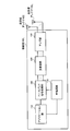
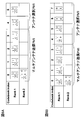
- FIG. 2 is a functional block diagram of the mobile station apparatus according to the embodiment of the present invention.
- the mobile station apparatus 100 n includes a plurality of transmit and receive antennas 102 1 ⁇ 102 N, an amplifier 104 corresponding to a plurality of receiving antennas 102 1 ⁇ 102 N, a transceiver unit 106, a baseband signal
- the processing unit 108, the call processing unit 110, and the application unit 112 are configured.
- Uplink data is input from the application unit 112 to the baseband signal processing unit 108.
- the baseband signal processing unit 108 performs retransmission control (H-ARQ (Hybrid ARQ)) processing, scheduling, transmission format selection, channel coding, transmission power setting, and the like, and forwards them to the transmission / reception unit 106 for each antenna.
- the transmission / reception unit 106 converts the baseband signal output from the baseband signal processing unit 108 into a radio frequency signal for each antenna.
- the frequency-converted signal is then amplified by the amplifier unit 104 and transmitted to each of the transmission / reception antennas 102 1 to 102 N.
- radio frequency signals received by the transmitting and receiving antennas 102 1 to 102 N are amplified by the amplifier unit 104 so that the received power is corrected to a constant power under AGC (Auto Gain Control).
- the amplified radio frequency signal is frequency-converted into a baseband signal by the transmission / reception unit 106.
- the baseband signal is subjected to predetermined processing (error correction, composite, etc.) by the baseband signal processing unit 108 and then transferred to the call processing unit 110 and the application unit 112.
- the call processing unit 110 manages communication with the base station apparatus, and the application unit 112 performs processing related to layers higher than the physical layer and the MAC layer.
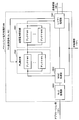
- FIG. 3 is a functional block diagram of the baseband signal processing unit of the mobile station apparatus.
- the baseband signal processing unit 108 includes a layer 1 processing unit 1081, a MAC processing unit 1082, an RLC processing unit 1083, a PL measurement unit 1084, and a transmission power setting unit 1085.
- the layer 1 processing unit 1081 mainly performs processing related to the physical layer.
- processing such as channel decoding, discrete Fourier transform (DFT) frequency demapping, inverse Fourier transform (IFFT), and data demodulation is performed on a signal received on the downlink.
- processing such as channel coding, data modulation, frequency mapping, and inverse Fourier transform (IFFT) is performed on a signal transmitted on the uplink.
- DFT discrete Fourier transform
- IFFT inverse Fourier transform
- IFFT inverse Fourier transform
- the MAC processing unit 1082 performs retransmission control (HARQ) at the MAC layer for a signal received in the downlink, analysis of scheduling information for the downlink (specification of PDSCH transmission format, identification of PDSCH resource block), and the like. Also, the MAC processing unit 1082 performs MAC retransmission control on signals transmitted on the uplink, analysis of uplink scheduling information (processing such as specifying a PUSCH transmission format, specifying a PUSCH resource block, and the like).
- HARQ retransmission control
- the RLC processing unit 1083 performs packet division, packet combination, retransmission control at the RLC layer, and the like on packets received on the uplink and packets transmitted on the downlink received from the application unit 112.
- the PL measurement unit 1084 measures RSRP (Reference Signal Received Power), and measures the path loss (PL) of each antenna from the transmission power (Tx power) of the downlink reference signal (DL RS) notified in advance and RSRP.
- RSRP Reference Signal Received Power
- the transmission power setting unit 1085 is used for representative value path loss (PL ′) used for transmission power control of each antenna or transmission power control of each antenna.
- the method described in the first aspect or the second aspect of the present invention can be used for setting the representative value path loss (PL ′) used for transmission power control and setting the transmission power of each antenna.
- P max the total transmission power of each transmission antenna after distribution exceeds P max
- the total transmission power (P TX ) of the mobile station apparatus is set to P max and the transmission power (P TXn ′ ) of each transmission antenna is set.
- the mobile station apparatus can select the antenna selection PMI from the code book shown in FIG.
- the transmission power setting unit 1085 uses the representative value path loss (PL ′) based on the measured path loss (PL) measurement value. ), Determining the total transmission power (P TX ) of the mobile station device based on the representative value path loss (PL ′), and distributing the total transmission power (P TX ) to each transmission antenna Determining the transmission power of each transmission antenna. For example, among the path loss measurement values of each transmission antenna measured by the PL measurement unit 1084, the value with the smallest PL measurement value is set as the representative value path loss (PL ′), and the total transmission power is calculated using the above equation (1).
- the PL ′ setting method 2 and the P TXn determination method 1 in the first aspect are applied.
- the present invention is not limited to this, and other PL ′ setting methods and P TXn determination methods may be applied.
- each of the transmission power setting units 1085 has a path loss (PL) measurement value measured by each transmission antenna.
- the P TXn determination method 1 in the second aspect is applied, but the present invention is not limited to this, and another P TXn determination method may be applied.
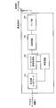
- FIG. 4 is a functional block diagram of the base station apparatus according to the embodiment of the present invention.
- the base station apparatus 200 includes a plurality of transmission / reception antennas 202 (only one is shown), an amplifier unit 204, a transmission / reception unit 206, a baseband signal processing unit 208, a call processing unit 210, The transmission path interface 212 is provided.
- a radio frequency signal received by the transmission / reception antenna 202 is amplified by the amplifier unit 204 so that the received power is corrected to a constant power under the AGC.
- the amplified radio frequency signal is frequency converted into a baseband signal in the transmission / reception unit 206.
- the baseband signal is subjected to predetermined processing (error correction, composite, etc.) by the baseband signal processing unit 208, and then transferred to an access gateway device (not shown) via the transmission path interface 212.
- the access gateway device is connected to the core network and manages each mobile station.
- Downlink data is input from the host device to the baseband signal processing unit 208 via the transmission path interface 212.
- the baseband signal processing unit 208 In the baseband signal processing unit 208, retransmission control (H-ARQ (Hybrid ARQ)) processing, scheduling, transmission format selection, channel coding, and the like are performed and transferred to the transmission / reception unit 206.
- the transmission / reception unit 206 converts the frequency of the baseband signal output from the baseband signal processing unit 208 into a radio frequency signal. The frequency-converted signal is then amplified by the amplifier unit 204 and transmitted from the transmission / reception antenna 202.
- the call processing unit 210 transmits / receives a call processing control signal to / from a radio control station of the host device, and manages the state of the base station device 200 and allocates resources.
- the processing in the layer 1 processing unit 2081 and the MAC processing unit 2082 is performed based on the communication state set in the call processing unit 210 between the base station device 200 and the mobile station device 100 n .
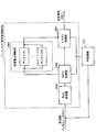
- FIG. 5 is a functional block diagram of the baseband signal processing unit of the base station apparatus.
- the baseband signal processing unit 208 includes a layer 1 processing unit 2081, a MAC (Medium Access Control) processing unit 2082, an RLC processing unit 2083, and a transmission power control unit 2084. .
- the layer 1 processing unit 2081 mainly performs processing related to the physical layer.
- processing such as channel decoding, discrete Fourier transform (DFT), frequency demapping, inverse Fourier transform (IFFT), and data demodulation is performed on the signal received on the uplink.
- processing such as channel coding, data modulation, frequency mapping, and inverse Fourier transform (IFFT) is performed on a signal transmitted in the downlink.
- DFT discrete Fourier transform
- IFFT inverse Fourier transform
- IFFT inverse Fourier transform
- the MAC processing unit 2082 performs processing such as retransmission control (HARQ) in the MAC layer for signals received on the uplink, scheduling for uplink / downlink, selection of PUSCH / PDSCH transmission format, selection of PUSCH / PDSCH resource block, and the like. I do.
- HARQ retransmission control
- the RLC processing unit 2083 performs packet division, packet combination, retransmission control at the RLC layer, etc. on packets received on the uplink / packets transmitted on the downlink.
- the transmission power control unit 2084 manages transmission power information of the mobile station apparatus, and sets and notifies a TPC command. In addition, considering the gain difference of each transmission antenna of the mobile station apparatus, the mobile station apparatus is notified by a higher layer signaling or a TPC command in PDCCH. Note that the correction value (f (i)) by the TPC command is commonly controlled for each transmission antenna or a plurality of transmission antennas in the mobile station apparatus. Further, when it is assumed that the total transmission power of each transmission antenna after distribution exceeds P max , the antenna selection PMI may be notified to the mobile station apparatus.
- the transmission power control method As described above, according to the transmission power control method according to the present embodiment, even when the mobile station apparatus includes a plurality of transmission antennas, the transmission power is considered in consideration of the path loss (PL) of each transmission antenna. By controlling this, it is possible to appropriately control uplink transmission power.
- PL path loss
- the present invention has an effect that the transmission power of a mobile station apparatus having a plurality of transmission antennas can be appropriately controlled, and in particular, a transmission power control method for controlling uplink transmission power, and a base station apparatus And useful for mobile station devices.
Landscapes
- Engineering & Computer Science (AREA)
- Computer Networks & Wireless Communication (AREA)
- Signal Processing (AREA)
- Mobile Radio Communication Systems (AREA)
Priority Applications (5)
| Application Number | Priority Date | Filing Date | Title |
|---|---|---|---|
| CN201180027783.7A CN102948226B (zh) | 2010-04-05 | 2011-04-05 | 发送功率控制方法和移动台装置 |
| MX2012011499A MX2012011499A (es) | 2010-04-05 | 2011-04-05 | Metodo de control de potencia de transmision y dispositivo de estacion movil. |
| KR1020127026872A KR20130024898A (ko) | 2010-04-05 | 2011-04-05 | 송신전력 제어방법 및 이동국장치 |
| US13/261,461 US8929232B2 (en) | 2010-04-05 | 2011-04-05 | Transmission power control method and mobile station apparatus |
| EP11765893.0A EP2557864A4 (en) | 2010-04-05 | 2011-04-05 | POWER TRANSMISSION CONTROL METHOD AND MOBILE STATION DEVICE |
Applications Claiming Priority (4)
| Application Number | Priority Date | Filing Date | Title |
|---|---|---|---|
| JP2010-087384 | 2010-04-05 | ||
| JP2010087384 | 2010-04-05 | ||
| JP2010-181813 | 2010-08-16 | ||
| JP2010181813A JP5149348B2 (ja) | 2010-04-05 | 2010-08-16 | 送信電力制御方法及び移動局装置 |
Publications (1)
| Publication Number | Publication Date |
|---|---|
| WO2011125993A1 true WO2011125993A1 (ja) | 2011-10-13 |
Family
ID=44762929
Family Applications (1)
| Application Number | Title | Priority Date | Filing Date |
|---|---|---|---|
| PCT/JP2011/058570 WO2011125993A1 (ja) | 2010-04-05 | 2011-04-05 | 送信電力制御方法及び移動局装置 |
Country Status (7)
| Country | Link |
|---|---|
| US (1) | US8929232B2 (zh) |
| EP (1) | EP2557864A4 (zh) |
| JP (1) | JP5149348B2 (zh) |
| KR (1) | KR20130024898A (zh) |
| CN (1) | CN102948226B (zh) |
| MX (1) | MX2012011499A (zh) |
| WO (1) | WO2011125993A1 (zh) |
Cited By (1)
| Publication number | Priority date | Publication date | Assignee | Title |
|---|---|---|---|---|
| CN103634889A (zh) * | 2012-08-21 | 2014-03-12 | 中国移动通信集团设计院有限公司 | 发射功率调整方法及装置 |
Families Citing this family (17)
| Publication number | Priority date | Publication date | Assignee | Title |
|---|---|---|---|---|
| KR101430856B1 (ko) * | 2010-04-09 | 2014-08-18 | 인터디지탈 패튼 홀딩스, 인크 | 상향링크에서의 폐루프 전송 다이버시티 및 mimo에 대한 전력 제어 방법 및 장치 |
| EP4221048A1 (en) * | 2011-05-02 | 2023-08-02 | BlackBerry Limited | Methods and systems of wireless communication with remote radio heads |
| CN104471999B (zh) * | 2012-08-17 | 2018-12-14 | 华为技术有限公司 | 上行控制信息的发送方法和装置 |
| KR102008467B1 (ko) * | 2012-12-27 | 2019-08-07 | 삼성전자주식회사 | 빔포밍 기반 무선 통신시스템의 상향링크 전력 제어 방법 및 장치 |
| EP2787662B1 (en) * | 2013-04-05 | 2018-02-28 | Telefonaktiebolaget LM Ericsson (publ) | Antenna port detection |
| US20170289920A1 (en) * | 2016-03-29 | 2017-10-05 | Futurewei Technologies, Inc. | Method and Apparatus for Resource and Power Allocation in Non-Orthogonal Uplink Transmissions |
| US10630410B2 (en) | 2016-05-13 | 2020-04-21 | Telefonaktiebolaget Lm Ericsson (Publ) | Network architecture, methods, and devices for a wireless communications network |
| US10367677B2 (en) * | 2016-05-13 | 2019-07-30 | Telefonaktiebolaget Lm Ericsson (Publ) | Network architecture, methods, and devices for a wireless communications network |
| JP6994304B2 (ja) * | 2017-03-02 | 2022-01-14 | 株式会社Nttドコモ | 無線端末、送信電力制御方法、および無線基地局 |
| KR102439792B1 (ko) * | 2018-02-14 | 2022-09-02 | 삼성전자주식회사 | 무선 통신 시스템에서 송신 전력을 결정하기 위한 장치 및 방법 |
| CN110475330B (zh) * | 2018-05-11 | 2021-05-25 | 电信科学技术研究院有限公司 | 一种上行功率控制方法、终端及网络设备 |
| US20200145929A1 (en) * | 2018-11-01 | 2020-05-07 | Qualcomm Incorporated | Power control for multi-panel transmission |
| WO2020124506A1 (zh) * | 2018-12-20 | 2020-06-25 | Oppo广东移动通信有限公司 | 确定天线的发射功率的方法、终端设备和网络设备 |
| CN112640539B (zh) * | 2018-12-25 | 2023-04-28 | Oppo广东移动通信有限公司 | 一种上行传输的功率控制方法及终端设备、网络设备 |
| CN112398622B (zh) * | 2019-08-16 | 2022-05-20 | 大唐移动通信设备有限公司 | 一种上行发送方法、终端及网络侧设备 |
| CN111212482B (zh) * | 2020-01-13 | 2022-05-24 | 普联技术有限公司 | 无线通信控制方法、装置、设备及计算机可读存储介质 |
| CN112929105B (zh) * | 2021-01-22 | 2022-05-13 | 中国铁塔股份有限公司 | 信号源间距确定方法、装置和电子设备 |
Citations (3)
| Publication number | Priority date | Publication date | Assignee | Title |
|---|---|---|---|---|
| JP2000040988A (ja) * | 1998-07-23 | 2000-02-08 | Sony Corp | 無線通信装置 |
| JP2002094451A (ja) * | 2000-09-12 | 2002-03-29 | Ntt Docomo Inc | Cdma無線送信装置、cdma無線送受信システムおよびcdma無線送信装置の送信電力制御方法ならびにcdma無線送受信システムにおける無線送信装置の送信電力制御方法 |
| JP2008258937A (ja) * | 2007-04-05 | 2008-10-23 | Matsushita Electric Ind Co Ltd | 伝搬環境推定方法、装置及び通信方法 |
Family Cites Families (4)
| Publication number | Priority date | Publication date | Assignee | Title |
|---|---|---|---|---|
| JP5084044B2 (ja) * | 2008-08-05 | 2012-11-28 | シャープ株式会社 | 無線通信システム、移動局装置及び無線通信方法 |
| JP5147123B2 (ja) * | 2008-08-05 | 2013-02-20 | シャープ株式会社 | 無線通信システム、基地局装置、移動局装置及び無線通信方法 |
| US8583160B2 (en) * | 2009-05-04 | 2013-11-12 | Qualcomm Incorporated | Uplink power control for wireless communication |
| US9144040B2 (en) * | 2010-04-01 | 2015-09-22 | Futurewei Technologies, Inc. | System and method for uplink multi-antenna power control in a communications system |
-
2010
- 2010-08-16 JP JP2010181813A patent/JP5149348B2/ja active Active
-
2011
- 2011-04-05 EP EP11765893.0A patent/EP2557864A4/en not_active Withdrawn
- 2011-04-05 MX MX2012011499A patent/MX2012011499A/es active IP Right Grant
- 2011-04-05 US US13/261,461 patent/US8929232B2/en not_active Expired - Fee Related
- 2011-04-05 WO PCT/JP2011/058570 patent/WO2011125993A1/ja active Application Filing
- 2011-04-05 CN CN201180027783.7A patent/CN102948226B/zh not_active Expired - Fee Related
- 2011-04-05 KR KR1020127026872A patent/KR20130024898A/ko not_active Application Discontinuation
Patent Citations (3)
| Publication number | Priority date | Publication date | Assignee | Title |
|---|---|---|---|---|
| JP2000040988A (ja) * | 1998-07-23 | 2000-02-08 | Sony Corp | 無線通信装置 |
| JP2002094451A (ja) * | 2000-09-12 | 2002-03-29 | Ntt Docomo Inc | Cdma無線送信装置、cdma無線送受信システムおよびcdma無線送信装置の送信電力制御方法ならびにcdma無線送受信システムにおける無線送信装置の送信電力制御方法 |
| JP2008258937A (ja) * | 2007-04-05 | 2008-10-23 | Matsushita Electric Ind Co Ltd | 伝搬環境推定方法、装置及び通信方法 |
Non-Patent Citations (3)
| Title |
|---|
| 3GPP TS 36.213 V9.1.0, March 2010 (2010-03-01), pages 9 - 12 * |
| 3GPP: "Evolved Universal Terrestrial Radio Access (E-UTRA); Physical layer procedures (3GPP, TS36.213, V8.2.0,)", 3GPP |
| See also references of EP2557864A4 * |
Cited By (1)
| Publication number | Priority date | Publication date | Assignee | Title |
|---|---|---|---|---|
| CN103634889A (zh) * | 2012-08-21 | 2014-03-12 | 中国移动通信集团设计院有限公司 | 发射功率调整方法及装置 |
Also Published As
| Publication number | Publication date |
|---|---|
| EP2557864A1 (en) | 2013-02-13 |
| MX2012011499A (es) | 2012-12-17 |
| US8929232B2 (en) | 2015-01-06 |
| JP2011234334A (ja) | 2011-11-17 |
| EP2557864A4 (en) | 2013-12-04 |
| KR20130024898A (ko) | 2013-03-08 |
| CN102948226A (zh) | 2013-02-27 |
| JP5149348B2 (ja) | 2013-02-20 |
| US20130100828A1 (en) | 2013-04-25 |
| CN102948226B (zh) | 2016-03-23 |
Similar Documents
| Publication | Publication Date | Title |
|---|---|---|
| JP5149348B2 (ja) | 送信電力制御方法及び移動局装置 | |
| US10313984B2 (en) | User terminal and radio communication method | |
| KR102269476B1 (ko) | 무선 전력 제어를 위한 시스템 및 방법 | |
| US9894618B2 (en) | Wireless device for controlling transmission power | |
| KR101750369B1 (ko) | 분산 안테나를 사용하는 이동 통신 시스템에서 상향 링크 전력 제어 방법 및 장치 | |
| JP5588236B2 (ja) | 送信電力制御方法、移動端末装置及び無線基地局装置 | |
| WO2011083797A1 (ja) | 移動端末装置、無線基地局装置及び無線通信方法 | |
| WO2018202083A9 (zh) | 功率余量的上报方法和装置 | |
| US8843171B2 (en) | Transmission power control method, base station apparatus and mobile station apparatus | |
| KR20110052593A (ko) | 폐 루프 송신전력 제어방법 및 무선기지국장치 | |
| JP5080607B2 (ja) | 無線基地局装置及び送信電力制御方法 | |
| KR20130061586A (ko) | 참조 신호 전송 방법 및 장치와 이를 이용한 상향링크 전송 방법 및 장치 | |
| JP2016518061A (ja) | マルチリンク接続のアップリンク送信電力制御のための方法および装置 | |
| US20170041121A1 (en) | Method for transmitting and receiving for power control factor related to considering self-interference cancellation in wireless communication system using fdr mode and devices therefor | |
| EP2777334A2 (en) | Uplink power control for wireless communications | |
| JP2013123141A (ja) | 基地局、端末、通信システムおよび通信方法 | |
| US9185661B2 (en) | Performing power control based on nominal packet size | |
| KR20130036383A (ko) | 무선 통신 시스템에서 상향링크 전송 전력을 제어하는 장치 및 방법 | |
| JP6609357B2 (ja) | 無線基地局及びユーザ端末 | |
| WO2024060190A1 (en) | Closed-loop antenna selection for a single transmitter wireless device | |
| WO2012093454A1 (ja) | 送信装置及び送信方法 | |
| Bautista et al. | UE-based adaptive uplink power control to enhance cell capacity of LTE systems |
Legal Events
| Date | Code | Title | Description |
|---|---|---|---|
| WWE | Wipo information: entry into national phase |
Ref document number: 201180027783.7 Country of ref document: CN |
|
| 121 | Ep: the epo has been informed by wipo that ep was designated in this application |
Ref document number: 11765893 Country of ref document: EP Kind code of ref document: A1 |
|
| WWE | Wipo information: entry into national phase |
Ref document number: MX/A/2012/011499 Country of ref document: MX |
|
| NENP | Non-entry into the national phase |
Ref country code: DE |
|
| WWE | Wipo information: entry into national phase |
Ref document number: 8640/CHENP/2012 Country of ref document: IN |
|
| ENP | Entry into the national phase |
Ref document number: 20127026872 Country of ref document: KR Kind code of ref document: A |
|
| REEP | Request for entry into the european phase |
Ref document number: 2011765893 Country of ref document: EP |
|
| WWE | Wipo information: entry into national phase |
Ref document number: 2011765893 Country of ref document: EP |
|
| WWE | Wipo information: entry into national phase |
Ref document number: 13261461 Country of ref document: US |