WO2011125202A1 - リチウム二次電池 - Google Patents
リチウム二次電池 Download PDFInfo
- Publication number
- WO2011125202A1 WO2011125202A1 PCT/JP2010/056384 JP2010056384W WO2011125202A1 WO 2011125202 A1 WO2011125202 A1 WO 2011125202A1 JP 2010056384 W JP2010056384 W JP 2010056384W WO 2011125202 A1 WO2011125202 A1 WO 2011125202A1
- Authority
- WO
- WIPO (PCT)
- Prior art keywords
- active material
- electrode
- life
- secondary battery
- lithium secondary
- Prior art date
- Legal status (The legal status is an assumption and is not a legal conclusion. Google has not performed a legal analysis and makes no representation as to the accuracy of the status listed.)
- Ceased
Links
Images




Classifications
-
- H—ELECTRICITY
- H01—ELECTRIC ELEMENTS
- H01M—PROCESSES OR MEANS, e.g. BATTERIES, FOR THE DIRECT CONVERSION OF CHEMICAL ENERGY INTO ELECTRICAL ENERGY
- H01M4/00—Electrodes
- H01M4/02—Electrodes composed of, or comprising, active material
- H01M4/36—Selection of substances as active materials, active masses, active liquids
- H01M4/362—Composites
- H01M4/364—Composites as mixtures
-
- H—ELECTRICITY
- H01—ELECTRIC ELEMENTS
- H01M—PROCESSES OR MEANS, e.g. BATTERIES, FOR THE DIRECT CONVERSION OF CHEMICAL ENERGY INTO ELECTRICAL ENERGY
- H01M4/00—Electrodes
- H01M4/02—Electrodes composed of, or comprising, active material
- H01M4/36—Selection of substances as active materials, active masses, active liquids
- H01M4/48—Selection of substances as active materials, active masses, active liquids of inorganic oxides or hydroxides
- H01M4/52—Selection of substances as active materials, active masses, active liquids of inorganic oxides or hydroxides of nickel, cobalt or iron
- H01M4/525—Selection of substances as active materials, active masses, active liquids of inorganic oxides or hydroxides of nickel, cobalt or iron of mixed oxides or hydroxides containing iron, cobalt or nickel for inserting or intercalating light metals, e.g. LiNiO2, LiCoO2 or LiCoOxFy
-
- Y—GENERAL TAGGING OF NEW TECHNOLOGICAL DEVELOPMENTS; GENERAL TAGGING OF CROSS-SECTIONAL TECHNOLOGIES SPANNING OVER SEVERAL SECTIONS OF THE IPC; TECHNICAL SUBJECTS COVERED BY FORMER USPC CROSS-REFERENCE ART COLLECTIONS [XRACs] AND DIGESTS
- Y02—TECHNOLOGIES OR APPLICATIONS FOR MITIGATION OR ADAPTATION AGAINST CLIMATE CHANGE
- Y02E—REDUCTION OF GREENHOUSE GAS [GHG] EMISSIONS, RELATED TO ENERGY GENERATION, TRANSMISSION OR DISTRIBUTION
- Y02E60/00—Enabling technologies; Technologies with a potential or indirect contribution to GHG emissions mitigation
- Y02E60/10—Energy storage using batteries
-
- Y—GENERAL TAGGING OF NEW TECHNOLOGICAL DEVELOPMENTS; GENERAL TAGGING OF CROSS-SECTIONAL TECHNOLOGIES SPANNING OVER SEVERAL SECTIONS OF THE IPC; TECHNICAL SUBJECTS COVERED BY FORMER USPC CROSS-REFERENCE ART COLLECTIONS [XRACs] AND DIGESTS
- Y02—TECHNOLOGIES OR APPLICATIONS FOR MITIGATION OR ADAPTATION AGAINST CLIMATE CHANGE
- Y02P—CLIMATE CHANGE MITIGATION TECHNOLOGIES IN THE PRODUCTION OR PROCESSING OF GOODS
- Y02P70/00—Climate change mitigation technologies in the production process for final industrial or consumer products
- Y02P70/50—Manufacturing or production processes characterised by the final manufactured product
Definitions
- the present invention relates to a lithium secondary battery using an iron oxide-based active material.
- Lithium secondary batteries that are charged and discharged by Li ions traveling between a positive electrode and a negative electrode that are provided with a material (active material) capable of reversibly occluding and releasing lithium (Li) are known.
- Patent Documents 1 to 4 are listed as prior art documents.
- Patent Document 1 discloses a conversion-type charge / discharge reaction, that is, when Li is inserted into a metal compound, the compound decomposes into a metal and a Li compound with reduction, and Li is released again in the reverse reaction. A charge / discharge reaction in which a metal compound is regenerated is introduced.
- Patent Document 1 discloses transition metal particles generated from the active material by discharge in a non-aqueous battery using an oxide, fluoride, sulfide, or the like of a transition metal as an active material (the transition metal is reduced). It is described that the cycle characteristics of the battery are improved by setting the particle diameter of the resulting metal particles to 500 nm or less.
- a lithium secondary battery used as a power source for a motor (electric motor) mounted on a vehicle such as an automobile requires a large number of batteries as compared with a lithium secondary battery for portable devices. The significance of reduction is particularly great.
- Iron oxide has been proposed as a material that can be converted and charged and discharged and can be an inexpensive active material.
- an iron oxide such as Fe 2 O 3 is generally a substance that has low reversibility of charge and discharge and is difficult to apply to a secondary battery (paragraph 0006 of Patent Document 2). etc).
- Patent Document 1 only three types of Co 3 O 4 , CuS, and FeF 3 have specific experimental data shown in Patent Document 1, and iron oxide (oxide containing iron as a constituent element) was used. There are no specific examples. Further, in Patent Document 1, a battery is manufactured using a material having a small particle size (30 nm to 3200 nm in FeF 3 ) as a raw material in order to make the particle diameter of transition metal particles generated by discharge less than 500 nm.
- nanometer-sized powders are generally expensive and difficult to handle. For example, such powders tend to agglomerate and tend to be difficult to mix uniformly with other powder materials or to be dispersed in a solvent.
- the present invention relates to a lithium secondary battery including an iron oxide-based active material that can be charged and discharged by a conversion reaction, which shows improved coulomb efficiency and is suitable for reducing production costs, and It aims at providing the manufacturing method.
- the lithium secondary battery disclosed herein has a configuration in which a positive electrode having a positive electrode active material and a negative electrode having a negative electrode active material are housed in a battery container together with a nonaqueous electrolyte.
- One of the positive electrode and the negative electrode is an iron oxide electrode including a mixture (iron oxide active material) of Fe 2 O 3 and LiFe 5 O 8 as the active material.
- the coulomb efficiency (particularly, the initial coulomb efficiency) can be improved even when charging / discharging is performed under conditions involving a conversion reaction, and a high level capacity can be maintained.
- inexpensive iron oxide is used and usable iron oxide is not limited to nanoparticles, it is advantageous in terms of raw material cost, handling property, and the like. Therefore, it is suitable for reducing production costs.
- lithium secondary battery refers to a secondary battery that uses lithium ions as electrolyte ions and is charged and discharged by the movement of lithium ions between positive and negative electrodes, and uses metallic lithium as an electrode active material. And those not using metallic lithium.
- the technology disclosed herein is applied to, for example, a lithium secondary battery that does not use metallic lithium as an electrode active material.
- a secondary battery generally called a lithium ion secondary battery is a typical example included in the lithium secondary battery in this specification.
- the active material is obtained by converting a part of Fe 2 O 3 into LiFe 5 O 8 by mixing and firing Fe 2 O 3 with a lithium compound. According to this aspect, it is possible to easily manufacture an iron oxide-based active material in which the Fe 2 O 3 phase and the LiFe 5 O 8 phase are appropriately mixed. Such an embodiment is suitable for reducing production costs.
- the active material during assembly of the battery, it is preferable less than 80 mass% to 100 mass% of the total mass of Fe 2 O 3 and LiFe 5 O 8 is LiFe 5 O 8. According to the iron oxide-based electrode including an active material having such a composition, higher coulomb efficiency can be realized while maintaining a high level of capacity.
- the lithium secondary battery disclosed herein typically has charge / discharge conditions in which at least a part of Fe in the active material is reduced to zero valence when Li is inserted (doped) into the active material. Used in According to such charge / discharge conditions, a large capacity can be realized because of the large valence change that Fe is reduced to a simple substance when Li is inserted. Further, by using a mixture of Fe 2 O 3 and LiFe 5 O 8 instead of Fe 2 O 3 alone as an active material, improved Coulomb efficiency can be realized even in charge and discharge with a conversion reaction. Therefore, both capacity and coulomb efficiency can be achieved at a high level.
- a method for manufacturing a lithium secondary battery including an iron oxide electrode includes a step of assembling a battery by housing a positive electrode having a positive electrode active material and a negative electrode having a negative electrode active material together with a non-aqueous electrolyte in a battery container.
- one of the positive electrode and the negative electrode is an iron oxide-based electrode including a mixture of Fe 2 O 3 and LiFe 5 O 8 as the active material.
- the manufacturing method may further include a step of inserting Li into the active material until the potential of the iron oxide-based electrode is 0.1 V or less with respect to lithium metal. According to the Li insertion step, at least a part of Fe contained in the active material can be reduced to zero. Therefore, a high capacity can be realized.
- This manufacturing method can be suitably employed as a method for manufacturing any of the lithium secondary batteries disclosed herein.
- the manufacturing method may further include a step of preparing a mixture of Fe 2 O 3 and LiFe 5 O 8 .
- the mixture may, for example, a Fe 2 O 3 were mixed with a lithium compound, Fe 2 O 3 -LiFe 5 O prepared by converting by firing it a part of Fe 2 O 3 in LiFe 5 O 8 It can be an 8 eutectic.
- the above manufacturing method may also include the step of producing an electrode comprising a mixture of Fe 2 O 3 and LiFe 5 O 8 as the active material. Such an electrode can be produced, for example, by holding an electrode mixture layer containing the active material on a current collector.
- the technology disclosed herein includes both a lithium secondary battery that includes the iron oxide-based electrode as a negative electrode and a lithium secondary battery that includes the iron oxide-based electrode as a positive electrode.
- a lithium secondary battery having an iron oxide-based electrode as a negative electrode is more preferable.
- Such a form is suitable for constructing a battery having a higher operating voltage.
- the active material of the counter electrode that is, the positive electrode
- the lithium secondary battery disclosed herein is suitable as a secondary battery mounted on a vehicle because it can realize a high capacity and can be highly productive.
- it can be suitably used as a power source for a motor (electric motor) of a vehicle such as an automobile.
- a vehicle including any lithium secondary battery disclosed herein (which may be a battery manufactured by any method disclosed herein).
- FIG. 1 is a partial cross-sectional perspective view schematically showing a configuration of a lithium secondary battery according to an embodiment.
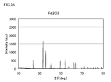
- FIG. 2A is a characteristic diagram showing an XRD pattern of the active material sample 0.
- FIG. 2B is a characteristic diagram showing an XRD pattern of the active material sample 1.
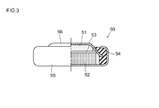
- FIG. 3 is a partial cross-sectional view schematically showing the configuration of the performance evaluation coin cell.
- FIG. 4 is a characteristic diagram showing a charge / discharge curve of a cell using samples 0 and 1.
- FIG. 5 is a side view schematically showing a vehicle (automobile) equipped with a lithium secondary battery according to an embodiment.
- FIG. 6 is an explanatory diagram showing a power supply system including a lithium secondary battery according to an embodiment.
- the technique disclosed here is characterized by using a mixture of Fe 2 O 3 and LiFe 5 O 8 as an active material for either positive or negative electrode.
- Fe 2 O 3 can occlude a large amount of Li by the reaction represented by the following formula: Fe 2 O 3 + 6Li ⁇ 3Li 2 O + 2Fe; however, this compound alone has room for further improvement in the reversibility of the above reaction.
- a mixture of Fe 2 O 3 and LiFe 5 O 8 (typically, a material (eutectic) in which an Fe 2 O 3 phase and a LiFe 5 O 8 phase are mixed) is activated. By using it as a substance, the Coulomb efficiency can be improved as compared with the case of using Fe 2 O 3 alone.
- LiFe 5 O 8 is used as an active material. Higher capacity can be realized compared to the case of using alone.
- the active material is a mixture of Fe 2 O 3 and LiFe 5 O 8 can be confirmed by, for example, X-ray diffraction (XRD) analysis of the active material. It is preferable to perform a powder XRD analysis like the Example mentioned later.
- XRD X-ray diffraction
- LiFe 5 O 8 / Fe 2 O 3 active material 80 mass% or more and less than 100 mass% (for example, 80 mass% or more and 99 mass% or less) of the total mass of Fe 2 O 3 and LiFe 5 O 8 is LiFe 5.
- O 8 is preferred.
- the iron oxide-based electrode including an active material having such a composition higher coulomb efficiency can be realized while maintaining a high level of capacity under charge / discharge conditions involving a conversion reaction.
- the ratio of LiFe 5 O 8 is too smaller than the above range, the effect of improving the Coulomb efficiency may not be sufficiently exhibited.
- the ratio of LiFe 5 O 8 is 100% by mass, the capacity decreases.
- Fe 2 weight ratio of O 3 and LiFe 5 LiFe 5 O 8 to the total mass of the O 8 is the mixture was fired LiFe 5 O 8 / Fe 2 O 3 active material of the Fe source and Li sources as described below Can be adjusted by adjusting the amount of Fe source and Li source used (for example, the ratio of the number of atoms of Fe and Li), the firing temperature, the firing time, the presence or absence of the use of a flux, and the like.
- Information on the mass ratio of LiFe 5 O 8 and Fe 2 O 3 contained in the LiFe 5 O 8 / Fe 2 O 3 active material can be grasped, for example, by analyzing the XRD pattern of the active material. Specifically, the mass ratio of LiFe 5 O 8 and Fe 2 O 3 can be determined by the method described in Examples described later.
- the matter disclosed by this specification includes Fe 2 O 3 and LiFe in the case where the XRD pattern is analyzed by the method described in the examples to be described later to determine the quantity ratio of LiFe 5 O 8 and Fe 2 O 3. 5 less than 80 wt% or more and 100 wt% of the total mass of the O 8 (e.g. 80 wt% or more 99 wt% or less) by using the active material is LiFe 5 O 8, the electrodes having such an active material, and the electrode Constructed batteries are included.
- the active material disclosed herein as a "mass ratio of LiFe 5 O 8 to the total mass of Fe 2 O 3 and LiFe 5 O 8", at the time of assembly of the battery using the active material (ie the active material In the unused stage).
- This composition generally coincides with the composition immediately after the production of the active material (for example, immediately after firing).
- the LiFe 5 O 8 / Fe 2 O 3 active material disclosed herein typically has a total mass of Fe 2 O 3 and LiFe 5 O 8 of 50% by mass or more of the total mass of the active material (preferably 70 mass% or more, for example 90 wt% or more), the total mass is substantially 100 wt% (i.e., it may be an active material) consisting essentially of LiFe 5 O 8 and Fe 2 O 3.
- the LiFe 5 O 8 / Fe 2 O 3 active material can be produced by mixing and firing Fe 2 O 3 as an Fe source and a lithium compound as a Li source. In this baking treatment, typically, a part of Fe 2 O 3 used as a raw material is converted to LiFe 5 O 8 . In a preferred embodiment, a powdered Fe source and a powdered Li source are mixed, and the mixed powder is fired to obtain a LiFe 5 O 8 / Fe 2 O 3 active material. According to the technology disclosed herein, by using Fe 2 O 3 as a raw material (Fe source), a fired product in which the Fe 2 O 3 phase and the LiFe 5 O 8 phase are appropriately mixed can be obtained efficiently. .
- Li source various lithium salts, for example, Li carbonate, nitrate, sulfate, phosphate, acetate, oxalate, hydroxide, and the like can be appropriately employed.
- Li one of these may be used alone, or two or more may be used in appropriate combination.
- a combination of Li sources that can be preferably employed a combination of Li 2 CO 3 and Li 2 SO 4 is exemplified.
- These lithium salts have a molar ratio of Li 2 CO 3 / Li 2 SO 4 of, for example, 1/10 to 10/1 (typically 1/10 to 1/1, such as 1/7 to 1/3). It is good to use by the quantitative ratio.
- the amount ratio of Fe source and Li source is usually such that the number of Li atoms with respect to one atom of Fe is 0.1 or more (preferably 0.2 or more). In a preferred embodiment, the number of Li atoms relative to one atom of Fe is 0.5 or more (for example, 0.8 or more). If the amount of Li used is too small, it becomes difficult to achieve the above-described preferred mass ratio of LiFe 5 O 8 , or the time required to produce a sufficient amount of LiFe 5 O 8 is increased. There is a possibility that the productivity of the substance tends to decrease. In general, it is appropriate that the number of Li atoms per one Fe is 10 or less, and preferably 5 or less (for example, 3 or less, or 2 or less). If the amount of Li used is too large, the operation of removing the excess (unreacted, ie, does not constitute lithium iron oxide) Li source from the fired product may be complicated and the raw material cost may increase. obtain.
- a flux can be used as appropriate.
- a typical example of a flux that can be preferably used in the technology disclosed herein is Na 2 SO 4 .
- one or two or more selected from various compounds that can be used together with the Fe source and the Li source to exhibit the action of lowering the melting point of the mixture can be used as the flux.
- Use of such a flux can contribute to improving the productivity of a fired product in which the Fe 2 O 3 phase and the LiFe 5 O 8 phase are suitably mixed (coexist).
- the amount of the flux used is not particularly limited, but it is usually appropriate to set it to about 0.1 to 5 mol (eg 0.2 to 1 mol) with respect to 1 mol of the Fe source.
- the firing atmosphere is appropriate as the firing atmosphere.
- an air atmosphere can be preferably used from the viewpoint of ease of manufacture and the like.
- the firing temperature may be set to a temperature at which LiFe 5 O 8 can be produced from Fe 2 O 3, and can be, for example, about 600 to 1000 ° C. (typically 750 to 850 ° C.).
- the firing time may be set so that a mass proportion of LiFe 5 O 8 capable of exhibiting the effects of the present invention is generated, and it is usually suitably 15 minutes or longer (preferably 30 minutes or longer). If the firing time is too long, the remaining amount of Fe 2 O 3 may be too small (for example, substantially all of Fe 2 O 3 is converted to LiFe 5 O 8 ). Also from the viewpoint of productivity, it is usually appropriate to set the firing time to 4 hours or shorter (for example, 2 hours or shorter).
- the matters disclosed by this specification include a mixed powder material (which may contain a flux) having a predetermined composition including an Fe source powder (typically Fe 2 O 3 powder) and a Li source powder.
- An active material manufacturing method including a step of determining firing conditions (typically at least a firing temperature and a firing time) and a step of firing the mixed powder material having the predetermined composition under the determined firing conditions. Can be included.
- the firing conditions are determined by appropriate preliminary experiments (for example, firing the mixed powder material having the predetermined composition at different firing temperatures and / or firing times, analyzing the obtained fired product, and analyzing the LiFe 5 O 8 content. This can be done through an experiment to determine the mass ratio. That is, it is not necessary to determine the firing conditions every time the active material is manufactured, and once appropriate firing conditions are determined, the manufacturing can be repeated by applying the conditions.
- An iron oxide-based electrode in the technology disclosed herein is an electrode mixture layer including a powder of LiFe 5 O 8 / Fe 2 O 3 active material, a binder (binder), and a conductive material used as necessary.
- an electrode having a configuration in which the active material is contained as a main component, that is, a composite layer containing 50% by mass or more is held by a current collector.
- the composite material layer can be formed, for example, by applying a liquid composition in which a composite material layer forming component is dispersed or dissolved in an appropriate solvent to the surface of the current collector, drying it, and pressing it as necessary. .
- molding a composite material layer formation component in desired shapes (plate shape, pellet shape, etc.) may be sufficient.
- a conductive member having the same material and shape as a current collector of a general lithium secondary battery electrode can be used.
- a conductive material typically a metal material
- Cu copper
- Ti titanium
- stainless steel stainless steel.
- a sheet-like current collector typically a metal foil
- the electrode mixture layer is easily formed and a high-capacity battery is easily constructed.
- the thickness of such a sheet-like current collector is not particularly limited, but a preferable thickness is 1 ⁇ m to 100 ⁇ m (more preferably 5 ⁇ m to 50 ⁇ m) in view of the balance between the capacity density of the battery and the strength of the substrate.
- a carbon material such as carbon black (for example, acetylene black) or graphite powder can be preferably used, like the conductive material in the electrode of a general lithium secondary battery.
- the binder polyvinylidene fluoride (PVDF), carboxymethyl cellulose (CMC), styrene butadiene rubber (SBR), or the like can be used.
- PVDF polyvinylidene fluoride
- CMC carboxymethyl cellulose
- SBR styrene butadiene rubber
- the amount of the conductive material used relative to 100 parts by mass of the LiFe 5 O 8 / Fe 2 O 3 active material can be, for example, 1 to 40 parts by mass (preferably 5 to 30 parts by mass).
- the amount of the binder used relative to 100 parts by mass of the active material can be, for example, 0.5 to 20 parts by mass.
- the lithium secondary battery disclosed herein is characterized in that either positive or negative electrode is an iron oxide-based electrode provided with a mixture of Fe 2 O 3 and LiFe 5 O 8 as an active material. Therefore, as long as the object of the present invention can be realized, the contents, materials, or compositions of other battery constituent materials and members are not particularly limited, and those similar to conventional lithium secondary batteries can be used.
- an active material capable of reversibly occluding and releasing Li is used as a counter electrode (that is, a positive electrode), a binder similar to the iron oxide-based electrode, and if necessary
- a positive electrode composite material attached to the current collector can be preferably used.
- the positive electrode current collector a rod-like body, a plate-like body, a foil-like body, a net-like body or the like mainly composed of aluminum, nickel, titanium, stainless steel, or the like can be used.
- an oxide-based positive electrode active material having a layered structure, an oxide-based positive electrode active material having a spinel structure, and the like used for a general lithium secondary battery can be preferably used.
- the layered oxide positive electrode active material include lithium transition metal oxides having a layered rock salt type crystal structure, such as lithium nickel oxide, lithium cobalt oxide, and lithium manganese oxide.
- lithium nickel oxide refers to an oxide (typically LiNiO 2 ) having only Li and Ni as constituent metal elements, and other one or more metal elements in addition to Li and Ni. It is also meant to include composite oxides containing Ni at a ratio equivalent to Ni or less than Ni (in terms of the number of atoms).
- the metal element is selected from the group consisting of, for example, Co, Al, Mn, Cr, Fe, V, Mg, Ti, Zr, Nb, Mo, W, Cu, Zn, Ga, In, Sn, La, and Ce. Or one or more elements.
- a ternary lithium transition metal oxide containing at least Ni, Co, and Mn as transition metal elements is used as a positive electrode active material. Used for substances.
- lithium manganese oxide having a spinel crystal structure As a typical example of the oxide-based positive electrode active material having a spinel structure, lithium manganese oxide having a spinel crystal structure can be given.
- this type of lithium manganese oxide include LiMn 2 O 4 and compounds having a composition in which part of the Mn is replaced with another metal element (lithium manganese oxide having a partially substituted spinel structure).
- Such a metal element can be, for example, one or more selected from Li, Mg, Al, Ni, Fe, Co, Cr, Cu, Be, B, Na, K, Ca, Si, Ge, and Ti.
- An oxide having a composition in which 50% or more of a metal element other than lithium is Mn in terms of the number of atoms is preferable.
- positive electrode active materials that can be employed in the technology disclosed herein include so-called polyanionic materials such as lithium iron phosphate, lithium manganese phosphate, lithium nickel phosphate, lithium cobalt phosphate, and lithium iron silicate.
- polyanionic materials such as lithium iron phosphate, lithium manganese phosphate, lithium nickel phosphate, lithium cobalt phosphate, and lithium iron silicate.
- a positive electrode active material is mentioned.
- a graphite, Sn alloy, Si alloy, lithium metal etc. can be used as a negative electrode active material, for example.
- a liquid electrolyte (nonaqueous electrolyte) containing a nonaqueous solvent and a lithium salt (supporting electrolyte) soluble in the solvent can be preferably used.
- the electrolyte may be a solid (gel) electrolyte in which a polymer is added to the electrolyte.
- the non-aqueous solvent is selected from non-aqueous solvents that are generally known to be usable for electrolytes of lithium secondary batteries, such as carbonates, esters, ethers, nitriles, sulfones, and lactones. 1 type, or 2 or more types can be used.
- Examples of the supporting electrolyte include LiPF 6 , LiBF 4 , LiN (SO 2 CF 3 ) 2 , LiN (SO 2 C 2 F 5 ) 2 , LiCF 3 SO 3 , LiC 4 F 9 SO 3 , LiC (SO 2 CF 3 3 ), LiClO 4, or the like, one or more selected from various lithium salts known to be capable of functioning as a supporting electrolyte for a lithium secondary battery can be used.
- the concentration of the supporting electrolyte (supporting salt) is not particularly limited, and can be, for example, the same level as that of a conventional lithium secondary battery.
- a nonaqueous electrolytic solution containing a supporting electrolyte at a concentration of about 0.1 mol / L to 5 mol / L (for example, about 0.8 mol / L to 1.5 mol / L) can be preferably used.
- an electrode body formed by stacking and winding a sheet-like positive electrode and a negative electrode is housed in a container together with a non-aqueous electrolyte.
- the shape (outer shape of the container) of the lithium secondary battery is not particularly limited, and may be, for example, a cylindrical shape, a square shape, a coin shape, or the like.
- a separator is interposed between the positive electrode and the negative electrode.
- a separator the thing similar to the separator used for a general lithium secondary battery can be used, and it does not specifically limit.
- a porous sheet made of a resin such as polyethylene (PE), polypropylene (PP), polyester, cellulose, or polyamide, a nonwoven fabric, or the like can be used.
- the electrolyte may also serve as a separator.
- a lithium secondary battery 10 includes a battery case (container) 15 having a shape in which an electrode body 11 including a positive electrode 12 and a negative electrode 14 can accommodate the electrode body together with a nonaqueous electrolytic solution 20. It has the structure accommodated in. At least a part of the nonaqueous electrolytic solution 20 is impregnated in the electrode body 11.
- the electrode body 11 includes a positive electrode (positive electrode sheet) 12 having a structure in which a positive electrode mixture layer 124 including a positive electrode active material is provided on a long sheet-like positive electrode current collector 122 and a negative electrode mixture layer including a negative electrode active material.
- a negative electrode (negative electrode sheet) 14 having a configuration in which 144 is provided on a long sheet-like negative electrode current collector 142 is superposed on two long sheet-like separators 13, and these are wound into a cylindrical shape. Is formed.
- the battery case 15 includes a bottomed cylindrical case main body 152 and a lid 154 that closes the opening.
- the lid 154 and the case main body 152 are both made of metal and insulated from each other, and are electrically connected to the positive and negative current collectors 122 and 142, respectively. That is, in the lithium secondary battery 10, the lid body 154 also serves as a positive electrode terminal, and the case body 152 serves as a negative electrode terminal.
- a portion where the current collector 122 is exposed without providing the positive electrode mixture layer (positive electrode mixture layer non-forming portion) is provided on one edge along the longitudinal direction of the positive electrode current collector 122.
- a portion where the current collector 142 is exposed without the negative electrode mixture layer (a negative electrode mixture layer non-forming portion) is provided on one edge along the longitudinal direction of the negative electrode current collector 142.
- the lid 154 and the case main body 152 are connected to the exposed portions.
- the lithium secondary battery disclosed herein is typically manufactured through a process of performing initial charge / discharge (so-called conditioning process) after assembling battery components.
- the LiFe 5 O 8 / Fe 2 O 3 active material has a potential of the iron oxide-based electrode of 0.1 V or less (typically 0.05 V on the basis of Li metal).
- the process of inserting Li is performed until it becomes about 0.01V, for example.
- the Li insertion step at least a part (typically at least 50 atomic% or more, preferably 75 atomic% or more) of Fe contained in the active material can be reduced to zero valence by a conversion reaction. Therefore, a high capacity can be realized.
- Li insertion step 1000 mAh or more of Li is inserted per 1 g of LiFe 5 O 8 / Fe 2 O 3 active material (that is, a Li insertion capacity of 1000 mAh). / G or more).
- the rate at which Li is inserted into the LiFe 5 O 8 / Fe 2 O 3 active material is the theoretical value of the Li insertion capacity of the active material per hour (the LiFe 5 O 8 /
- the charge amount required to reduce all the Fe contained in the Fe 2 O 3 active material to zero is preferably about 0.014 to 1 times.
- the Li insertion rate when using the lithium secondary battery after the initial charge / discharge is not limited to the Li introduction rate during the initial charge / discharge. That is, it may be the same as or different from the initial charge / discharge.
- the matters disclosed by this specification include any of the lithium secondary batteries disclosed herein (for example, a lithium secondary battery including the iron oxide-based electrode as a negative electrode) and the iron oxide-based electrode. It includes a method for use under charge / discharge conditions in which the lower limit potential is set to 0.1 V or less (typically 0 V to 0.1 V, for example, 0 V to 0.05 V) with respect to the metal-to-metal Li. Further, such a lithium secondary battery (may be in the form of an assembled battery formed by connecting a plurality of batteries in series and / or in parallel), and a charge set so that the battery can be set to the above lower limit voltage.
- a power supply system including a control mechanism (control device) that controls the discharge conditions is included.
- the power supply system adjusts the operation of the load 102 according to the state of the lithium secondary battery 10, the load 102 connected thereto, and the lithium secondary battery 10, for example, as in the power supply system 100 shown in FIG. 6.
- the electronic control unit (ECU) 104 may be included.
- the load 102 may include a power consumer that consumes the power stored in the lithium secondary battery 10 and / or a power supply machine (charger) that supplies rechargeable power to the lithium secondary battery 10. Based on the predetermined information, the ECU 104 controls the load 102 so that the lower limit potential during charging and discharging of the iron oxide-based electrode is 0.1 V or less with respect to the metal Li.
- the typical configuration of the ECU 104 includes at least a ROM (read only memory) that stores a program for performing such control, and a CPU (central processing unit) that can execute the program.
- Examples of the predetermined information include the potential of an iron oxide-based electrode (which may be a positive electrode or a negative electrode) included in the lithium secondary battery 10, the voltage of the lithium secondary battery 10, and the lithium secondary battery.
- One or more of the 10 charging / discharging histories, etc. can be used.
- a lithium secondary battery 10 disclosed herein includes, for example, a vehicle (typically, an automobile, particularly a hybrid automobile, an electric automobile, a fuel shown in FIG. 5 as a component of a power supply system 100 shown in FIG. It can be mounted on a motor vehicle 1 equipped with an electric motor such as a battery car.
- Fe 2 O 3 a fraction having a particle size of 25 ⁇ m or less obtained by classifying commercially available Fe 2 O 3 powder material (manufactured by Kojundo Chemical Co., Ltd., average particle size 1 ⁇ m) was used. The average particle size of this fraction was 1.1 ⁇ m.
- the mixed sample was placed in an alumina crucible and fired in a muffle furnace.
- the temperature condition at the time of firing was such that it was heated from room temperature to 800 ° C. at a rate of temperature increase of 10 ° C./min, held at that temperature for 1 hour, and then naturally cooled (cooled).
- the firing atmosphere was atmospheric conditions.
- the fired product was crushed and washed three times with pure water to remove unreacted Li compound, and then dried with a vacuum dryer. Thereafter, pulverization and classification were further performed to prepare an active material powder (sample 1) having an average particle size of 1.5 ⁇ m.
- An active material powder (Sample 2) was prepared in the same manner as Sample 1 except that 0.5 mol of Li 2 CO 3 was used with respect to 5 mol of Fe 2 O 3 .
- An active material powder (Sample 3) was prepared in the same manner as Sample 1 except that 2 mol of Li 2 CO 3 was used with respect to 5 mol of Fe 2 O 3 .
- lithium secondary battery electrodes were prepared. Specifically, each active material sample, acetylene black (trade name “DENKA BLACK HS-100” manufactured by Denki Kagaku Kogyo Co., Ltd.) as a conductive material, and polyvinylidene fluoride (PVDF) as a binder, these materials was mixed with N-methylpyrrolidone (NMP) so that the mass ratio was 75:10:15 to prepare an electrode mixture composition. This composition was applied to one side of a 10 ⁇ m thick copper foil with a doctor blade so that the amount applied in terms of solid content was 2 mg / cm 2 , dried at 80 ° C. for 30 minutes, and then pressed.
- NMP N-methylpyrrolidone
- an iron oxide-based electrode sample having a composite material layer having a thickness of 10 ⁇ m on one surface of a copper foil (current collector) was obtained.
- these samples are referred to as electrode samples 0 to 4 in association with the active material samples used.
- LiPF 6 as a supporting salt in a mixed solvent of ethylene carbonate (EC), dimethyl carbonate (DMC) and ethyl methyl carbonate (EMC) in a volume ratio of 3: 3: 4 at a concentration of about 1 mol / L.
- EC ethylene carbonate
- DMC dimethyl carbonate
- EMC ethyl methyl carbonate
- a dissolved solution was prepared.
- Each electrolyte sample was punched into a circular shape having a diameter of about 16 mm, an iron oxide-based electrode, metallic lithium as a counter electrode (a metallic Li foil having a diameter of 19 mm and a thickness of 0.15 mm), and a separator.
- reference numeral 51 denotes an iron oxide electrode
- reference numeral 52 denotes a metal Li electrode
- reference numeral 53 denotes a separator impregnated with an electrolytic solution
- reference numeral 54 denotes a gasket
- reference numeral 55 denotes a container (Li electrode side terminal).
- Reference numeral 56 denotes a lid (iron oxide electrode side terminal).
- a current rate of 1/10 C for each coin cell in an environment of 25 ° C. (C indicates the amount of current that can fully charge each coin cell in one hour.
- the active material sample of each iron oxide electrode is used as an active material sample. Calculated based on the amount of charge required to reduce all the contained Fe to zero valence, that is, the theoretical value of the Li insertion capacity.) Until the terminal voltage reaches 0.01 V (lower limit voltage). Li was inserted (doped) into the electrode, and the capacity at this time (initial Li insertion capacity) was measured.
- FIG. 4 shows charge / discharge characteristic curves of the iron oxide-based electrode during the first Li insertion / release for the cell using the electrode sample 0 and the cell using the electrode sample 1.
- the solid line indicates the characteristics of the cell using the electrode sample 1
- the dotted line indicates the characteristics of the cell using the electrode sample 0.
- the lithium secondary battery provided by the technology disclosed herein can be used as a lithium secondary battery for various applications because it exhibits excellent performance as described above and can be highly productive. .
- it can be suitably used as a power source for a motor (electric motor) mounted on a vehicle such as an automobile.
Landscapes
- Chemical & Material Sciences (AREA)
- Composite Materials (AREA)
- Chemical Kinetics & Catalysis (AREA)
- Electrochemistry (AREA)
- General Chemical & Material Sciences (AREA)
- Inorganic Chemistry (AREA)
- Battery Electrode And Active Subsutance (AREA)
Abstract
コンバージョン反応により充放電可能な鉄酸化物系活物質を備え、改善されたクーロン効率を示し、かつ生産コストの低減にも適したリチウム二次電池10が提供される。その二次電池10は、正極活物質を有する正極12と負極活物質を有する負極14とが非水電解質20とともに電池容器15に収容された構成を有する。正極12および負極14のうち一方は、活物質としてFe2O3とLiFe5O8との混合物を備える鉄酸化物系電極である。
Description
本発明は、鉄酸化物系の活物質を用いたリチウム二次電池に関する。
リチウム(Li)を可逆的に吸蔵および放出し得る材料(活物質)を備えた正極と負極との間をLiイオンが行き来することによって充電および放電するリチウム二次電池が知られている。従来技術文献として特許文献1~4が挙げられる。
現在、負極用の活物質としてはグラファイトが広く用いられている。しかし、グラファイトでは6個の炭素原子当たり1個のLiがインターカレートするため、その充放電容量には372mAh/gの上限がある。そこで、グラファイトに勝る充放電容量を実現し得る活物質が種々検討されている。例えば特許文献1には、コンバージョン型の充放電反応、すなわち金属化合物中にLiが挿入されると該化合物が還元を伴って金属とLi化合物とに分解し、逆反応では再度Liが放出されて金属化合物が再生する、という充放電反応が紹介されている。
上記のようなコンバージョン反応は、金属が単体まで還元されるという大きな価数変化を伴うため、かかる反応を充放電に利用することにより、従来の活物質に比べて極めて大きな容量が実現され得る。しかし、一般にコンバージョン反応には、該反応の可逆性が低いという課題がある。この点に関し、特許文献1には、遷移金属の酸化物、フッ化物、硫化物等を活物質に用いた非水電池において、放電により上記活物質から生成する遷移金属粒子(上記遷移金属が還元されて生じた金属粒子)の粒子径を500nm以下とすることにより電池のサイクル特性が向上することが記載されている。
一方、リチウム二次電池の構成材料として、より安価な材料および/または生産性のよい(例えば、原料または製造過程で生じる中間材料の取扱性のよい)材料を採用することができれば、該電池の生産コストを低減し得るので有益である。自動車等の車両に搭載されるモータ(電動機)用電源としての用いられるリチウム二次電池では、携帯機器用のリチウム二次電池に比べて大型の電池が多数必要とされることから、生産コストを低減する意義が特に大きい。コンバージョン型の充放電が可能であってかつ安価な活物質となり得る材料として鉄酸化物が提案されている。しかし、Fe2O3のような鉄酸化物は、通常、充放電の可逆性が低く、二次電池への適用が困難な物質であることが知られている(特許文献2の第0006項等)。
また、特許文献1において具体的な実験データが示されているのはCo3O4,CuS,FeF3の三種類のみであり、鉄酸化物(鉄を構成元素として含む酸化物)を用いた具体的実施例はない。さらに、特許文献1では、放電により生成する遷移金属粒子の粒子径を500nm以下とするために、対応する小粒径の材料(FeF3では30nm~3200nm)を原料に用いて電池を製造しているが、このようなナノメートルサイズの粉末は一般に高価であり、取扱いも難しい。例えば、かかる粉末は凝集しやすいため、他の粉末材料と均一に混合したり、溶媒に分散させたりすることが困難となりがちである。したがって、使用可能な原料の選択肢が上記のような小粒径のものに限定されることは、生産コスト低減の観点から不利である。コンバージョン反応可能な活物質を用いた電池において、反応の可逆性(クーロン効率)を向上させる新たな技術が提供されれば有用である。
本発明は、コンバージョン反応により充放電可能な鉄酸化物系活物質を備えたリチウム二次電池であって、改善されたクーロン効率を示し、かつ生産コストの低減にも適したリチウム二次電池およびその製造方法の提供を目的とする。
ここに開示されるリチウム二次電池は、正極活物質を有する正極と負極活物質を有する負極とが非水電解質とともに電池容器に収容された構成を有する。前記正極および前記負極のうち一方は、前記活物質としてFe2O3とLiFe5O8との混合物(鉄酸化物系活物質)を備える鉄酸化物系電極である。かかる構成のリチウム二次電池によると、コンバージョン反応を伴う条件で充放電される場合にもクーロン効率(特に、初期クーロン効率)を改善し得、かつ高レベルの容量を維持することができる。また、安価な鉄酸化物を用い、しかも使用可能な鉄酸化物がナノ粒子に限られないので、原料コストや取扱性等の点で有利である。したがって生産コストの低減に適している。
なお、本明細書において「リチウム二次電池」とは、電解質イオンとしてリチウムイオンを利用し、正負極間のリチウムイオンの移動により充放電する二次電池をいい、電極活物質として金属リチウムを用いるもの、および金属リチウムを用いないものの双方を包含する意味である。ここに開示される技術は、例えば、電極活物質として金属リチウムを用いない形態のリチウム二次電池に適用される。一般にリチウムイオン二次電池と称される二次電池は、本明細書におけるリチウム二次電池に包含される一典型例である。
好ましい一態様では、前記活物質が、Fe2O3をリチウム化合物と混合して焼成することにより該Fe2O3の一部をLiFe5O8に変換して得られたものである。かかる態様によると、Fe2O3相とLiFe5O8相とが適切に混在した鉄酸化物系活物質を容易に製造することができる。かかる態様は生産コストの低減に適している。
前記活物質は、電池の組立時において、Fe2O3およびLiFe5O8の合計質量のうち80質量%以上100質量%未満がLiFe5O8であることが好ましい。かかる組成の活物質を備えた鉄酸化物系電極によると、高レベルの容量を維持しつつ、より高いクーロン効率が実現され得る。
ここに開示されるリチウム二次電池は、典型的には、前記活物質にLiが挿入(ドープ)される際に該活物質中のFeの少なくとも一部が0価まで還元される充放電条件で用いられる。かかる充放電条件によると、Li挿入時においてFeが単体まで還元されるという大きな価数変化を伴うため、高い容量が実現され得る。また、Fe2O3単独ではなくFe2O3とLiFe5O8との混合物を活物質に用いることにより、コンバージョン反応を伴う充放電においても改善されたクーロン効率が実現され得る。したがって、容量とクーロン効率とが高度なレベルで両立され得る。
この明細書によると、また、鉄酸化物系電極を備えたリチウム二次電池を製造する方法が適用される。その方法は、正極活物質を有する正極と負極活物質を有する負極とを非水電解質とともに電池容器に収容して電池を組み立てる工程を含む。ここで、前記正極および前記負極のうち一方は、前記活物質としてFe2O3およびLiFe5O8の混合物を備える鉄酸化物系電極である。上記製造方法は、また、前記活物質に、前記鉄酸化物系電極の電位が対金属リチウム基準で0.1V以下になるまでLiを挿入する工程を含み得る。かかるLi挿入工程によると、上記活物質に含まれるFeの少なくとも一部が0価まで還元され得る。したがって高い容量が実現され得る。この製造方法は、ここに開示されるいずれかのリチウム二次電池を製造する方法として好適に採用され得る。
上記製造方法は、さらに、Fe2O3とLiFe5O8との混合物を調製する工程を含み得る。上記混合物は、例えば、Fe2O3をリチウム化合物と混合し、それを焼成してFe2O3の一部をLiFe5O8に変換することにより調製されたFe2O3-LiFe5O8共晶体であり得る。上記製造方法は、また、Fe2O3およびLiFe5O8の混合物を活物質として備える電極を作製する工程を含み得る。かかる電極は、例えば、該活物質を含む電極合材層を集電体に保持させることにより作製され得る。
ここに開示される技術には、前記鉄酸化物系電極を負極として備えるリチウム二次電池、および、前記鉄酸化物系電極を正極として備えるリチウム二次電池、の双方が含まれる。鉄酸化物系電極を負極として備える形態のリチウム二次電池がより好ましい。かかる形態は、より作動電圧の高い電池を構築するのに適している。また、対極(すなわち正極)の活物質をより広い範囲から選択し得るので好ましい。
ここに開示されるリチウム二次電池は、高容量を実現し得、かつ生産性のよいものとなり得ることから、車両に搭載される二次電池として好適である。例えば、自動車等の車両のモータ(電動機)用の電源として好適に利用され得る。したがって、本発明によると、ここに開示されるいずれかのリチウム二次電池(ここに開示されるいずれかの方法により製造された電池であり得る)を備えた車両が提供される。
以下、本発明の好適な実施形態を説明する。なお、本明細書において特に言及している事項以外の事柄であって本発明の実施に必要な事柄は、当該分野における従来技術に基づく当業者の設計事項として把握され得る。本発明は、本明細書に開示されている内容と当該分野における技術常識とに基づいて実施することができる。
ここに開示される技術は、正負いずれかの電極の活物質としてFe2O3とLiFe5O8との混合物を利用することによって特徴づけられる。Fe2O3は、次式:Fe2O3+6Li→3Li2O+2Fe;で示される反応により多量のLiを吸蔵し得るが、この化合物単独では上記反応の可逆性において更なる改善の余地がある。ここに開示される技術によると、Fe2O3とLiFe5O8との混合物(典型的には、Fe2O3相とLiFe5O8相とが混在する材料(共晶体))を活物質として用いることにより、Fe2O3を単独で用いる場合に比べてクーロン効率が改善され得る。また、上記Fe2O3とLiFe5O8との混合物を活物質(以下、「LiFe5O8/Fe2O3活物質」ということもある。)として用いることにより、LiFe5O8を単独で用いる場合に比べて、より高い容量が実現され得る。活物質がFe2O3とLiFe5O8との混合物であることは、例えば、該活物質のX線回折(XRD;X-ray diffraction)分析により確認することができる。後述する実施例のように粉末XRD分析を行うことが好ましい。
上記LiFe5O8/Fe2O3活物質は、Fe2O3およびLiFe5O8の合計質量のうち80質量%以上100質量%未満(例えば80質量%以上99質量%以下)がLiFe5O8であることが好ましい。かかる組成の活物質を備えた鉄酸化物系電極によると、コンバージョン反応を伴う充放電条件において、高レベルの容量を維持しつつ、より高いクーロン効率が実現され得る。LiFe5O8の割合が上記範囲よりも少なすぎると、クーロン効率を向上させる効果が十分に発揮され難くなることがあり得る。LiFe5O8の割合を100質量%とすると容量が低下する。Fe2O3およびLiFe5O8の合計質量に占めるLiFe5O8の質量割合は、後述のようにFe源とLi源との混合物を焼成してLiFe5O8/Fe2O3活物質を製造する場合において、Fe源とLi源との使用量比(例えば、FeとLiとの原子数比)、焼成温度、焼成時間、融剤の使用有無、等により調節することができる。
LiFe5O8/Fe2O3活物質に含まれるLiFe5O8とFe2O3の質量比に関する情報は、例えば、当該活物質のXRDパターンを解析することにより把握することができる。具体的には、後述する実施例に記載した方法によって、LiFe5O8とFe2O3の質量比を求めることができる。この明細書により開示される事項には、後述する実施例に記載の方法でXRDパターンを解析してLiFe5O8とFe2O3の量比を求めた場合において、Fe2O3およびLiFe5O8の合計質量のうち80質量%以上100質量%未満(例えば80質量%以上99質量%以下)がLiFe5O8である活物質、かかる活物質を備える電極、および該電極を用いて構築された電池が包含される。
なお、ここに開示される活物質について「Fe2O3およびLiFe5O8の合計質量に占めるLiFe5O8の質量割合」とは、当該活物質を用いた電池の組立時(すなわち活物質の未使用段階)における組成を指す。この組成は、通常、上記活物質の製造直後(例えば焼成直後)の組成と概ね一致する。ここに開示されるLiFe5O8/Fe2O3活物質は、典型的には該活物質の全質量のうちFe2O3およびLiFe5O8の合計質量が50質量%以上(好ましくは70質量%以上、例えば90質量%以上)であり、上記合計質量が実質的に100質量%(すなわち、実質的にLiFe5O8およびFe2O3からなる活物質)であってもよい。
上記LiFe5O8/Fe2O3活物質は、Fe源としてのFe2O3とLi源としてのリチウム化合物とを混合して焼成することにより製造され得る。この焼成処理において、典型的には、原料に用いたFe2O3の一部がLiFe5O8に変換される。好ましい一態様では、粉末状のFe源と粉末状のLi源とを混合し、この混合粉末を焼成してLiFe5O8/Fe2O3活物質を得る。ここに開示される技術によると、原料(Fe源)としてFe2O3を用いることにより、Fe2O3相とLiFe5O8相とが適切に混在した焼成物を効率よく得ることができる。Li源としては、各種のリチウム塩、例えばLiの炭酸塩、硝酸塩、硫酸塩、リン酸塩、酢酸塩、シュウ酸塩、水酸化物、等を適宜採用することができる。Liとしては、これらのうち一種を単独で用いてもよく、二種以上を適宜組み合わせて用いてもよい。好ましく採用し得るLi源の組合せとして、Li2CO3とLi2SO4との組合せが例示される。これらのリチウム塩を、Li2CO3/Li2SO4のモル比が例えば1/10~10/1(典型的には1/10~1/1、例えば1/7~1/3)となる量比で用いるとよい。
Fe源とLi源との使用量比は、通常、1原子のFeに対するLiの原子数が0.1以上(好ましくは0.2以上)となる量比とすることが適当である。好ましい一態様では、1原子のFeに対するLiの原子数が0.5以上(例えば0.8以上)である。Liの使用量が少なすぎると、上述した好ましいLiFe5O8の質量割合が実現され難くなったり、十分な効果が発揮される量のLiFe5O8が生じるまでに要する時間が長くなって活物質の生産性が低下傾向となったりすることがあり得る。また、通常は、1原子のFeに対するLiの原子数を10以下とすることが適当であり、好ましくは5以下(例えば3以下であり、2以下であってもよい。)である。Liの使用量が多すぎると、焼成物から余分な(未反応の、すなわちリチウム鉄酸化物を構成しない)Li源を除去する操作が煩雑になったり、原料コストが増加したりする場合があり得る。
上記焼成にあたっては、適宜、融剤を使用することができる。ここに開示される技術において好ましく使用し得る融剤の一代表例としてNa2SO4が挙げられる。その他、Fe源およびLi源とともに用いられて混合物の融点を低下させる作用を発揮し得る各種の化合物から選択される一種または二種以上を融剤として用いることができる。このような融剤の使用は、Fe2O3相とLiFe5O8相とが好適に混在(共存)する焼成物の生産性向上に寄与し得る。融剤の使用量は特に限定されないが、通常は、Fe源1モルに対して0.1~5モル(例えば0.2~1モル)程度とすることが適当である。
焼成雰囲気としては酸化性雰囲気が適当である。製造容易性等の観点から、通常は大気雰囲気を好ましく採用することができる。焼成温度は、Fe2O3からLiFe5O8が生じ得る温度に設定すればよく、例えば600~1000℃(典型的には750~850℃)程度とすることができる。焼成時間は、本発明の効果が発揮され得る質量割合のLiFe5O8が生成するように設定すればよく、通常は15分以上(好ましくは30分以上)とすることが適当である。焼成時間を長くしすぎるとFe2O3の残量が少なくなりすぎる(例えば、Fe2O3の実質的に全部がLiFe5O8に変換される)虞がある。生産性の観点からも、通常は、焼成時間を4時間以下(例えば2時間以下)とすることが適当である。
なお、この明細書により開示される事項には、Fe源粉末(典型的にはFe2O3粉末)とLi源粉末とを含む所定組成の混合粉末材料(融剤を含有し得る。)を焼成してLiFe5O8/Fe2O3活物質を製造する方法であって、Fe2O3およびLiFe5O8の合計質量のうち80質量%以上100質量%未満がLiFe5O8となる焼成条件(典型的には、少なくとも焼成温度および焼成時間)を決定する工程と、その決定された焼成条件で上記所定組成の混合粉末材料を焼成する工程と、を包含する活物質製造方法が包含され得る。上記焼成条件の決定は、適当な予備実験(例えば、焼成温度および/または焼成時間を異ならせて上記所定組成の混合粉末材料を焼成し、得られた焼成物を分析してLiFe5O8の質量割合を求める実験)を通じて行うことができる。すなわち、活物質材料の製造を行う度毎に焼成条件を決定する必要はなく、いちど適切な焼成条件が決定されれば当該条件を適用して製造を繰り返すことも可能である。
ここに開示される技術における鉄酸化物系電極は、LiFe5O8/Fe2O3活物質の粉末とバインダ(結着剤)と必要に応じて用いられる導電材とを含む電極合材層(好ましくは、上記活物質を主成分、すなわち50質量%以上を占める成分として含む合材層)が集電体に保持された構成の電極であり得る。上記合材層は、例えば、合材層形成成分を適当な溶媒に分散または溶解させた液状組成物を集電体の表面に付与して乾燥させ、必要に応じてプレスすることにより形成され得る。あるいは、合材層形成成分を所望の形状(板状、ペレット状等)に成形してなる鉄酸化物系電極であってもよい。
上記集電体としては、一般的なリチウム二次電池用電極の集電体と同様の材質および形状を有する導電性部材を用いることができる。例えば、銅(Cu)、チタン(Ti)、ステンレス鋼等の導電性材料(典型的には金属材料)を主体とする棒状体、板状体、シート状(箔状)体、網状体等を用いることができる。上記電極合材層を形成しやすいこと、高容量の電池を構築しやすいこと等から、シート状の集電体(典型的には金属箔)を好ましく採用することができる。かかるシート状集電体の厚みは特に限定されないが、電池の容量密度と基体の強度との兼ね合いから好ましい厚みとして、1μm~100μm(より好ましくは5μm~50μm)程度の範囲が例示される。
上記導電材としては、一般的なリチウム二次電池の電極における導電材と同様、カーボンブラック(例えばアセチレンブラック)、グラファイト粉末等のカーボン材料を好ましく用いることができる。上記バインダとしては、ポリフッ化ビニリデン(PVDF)、カルボキシメチルセルロース(CMC)、スチレンブタジエンゴム(SBR)等を用いることができる。特に限定するものではないが、LiFe5O8/Fe2O3活物質100質量部に対する導電材の使用量は、例えば1~40質量部(好ましくは5~30質量部)とすることができる。また、上記活物質100質量部に対するバインダの使用量は、例えば0.5~20質量部とすることができる。
ここに開示されるリチウム二次電池は、正負いずれかの電極がFe2O3とLiFe5O8との混合物を活物質として備える鉄酸化物系電極であることによって特徴づけられる。したがって、本発明の目的を実現し得る限り、他の電池構成材料や部材等の内容、材質あるいは組成は特に制限されず、従来のリチウム二次電池と同様のもの等を用いることができる。
例えば、上記鉄酸化物系電極を負極として用いる場合、対極(すなわち正極)としては、Liを可逆的に吸蔵および放出可能な活物質を、上記鉄酸化物系電極と同様のバインダおよび必要に応じて使用される導電材等とともに正極合材として集電体に付着させた形態のものを好ましく使用し得る。正極集電体としては、アルミニウム、ニッケル、チタン、ステンレス鋼等を主体とする棒状体、板状体、箔状体、網状体等を用いることができる。
正極活物質としては、一般的なリチウム二次電池に用いられる層状構造の酸化物系正極活物質、スピネル構造の酸化物系正極活物質等を好ましく用いることができる。
層状構造の酸化物系正極活物質の例としては、リチウムニッケル酸化物、リチウムコバルト酸化物、リチウムマンガン酸化物等の、層状岩塩型の結晶構造を有するリチウム遷移金属酸化物が挙げられる。ここで「リチウムニッケル酸化物」とは、LiおよびNiのみを構成金属元素とする酸化物(典型的にはLiNiO2)の他、LiおよびNiに加えて他の一種または二種以上の金属元素をNiと同等またはNiよりも少ない割合(原子数換算)で含む複合酸化物をも包含する意味である。かかる金属元素は、例えば、Co,Al,Mn,Cr,Fe,V,Mg,Ti,Zr,Nb,Mo,W,Cu,Zn,Ga,In,Sn,LaおよびCeからなる群から選択される一種または二種以上の元素であり得る。リチウムコバルト酸化物およびリチウムマンガン酸化物についても同様である。好ましい一態様では、遷移金属元素として少なくともNi,CoおよびMnを含む(例えば、これら3種の遷移金属元素を概ね同程度の原子数比で含む)三元系のリチウム遷移金属酸化物を正極活物質に使用する。
層状構造の酸化物系正極活物質の例としては、リチウムニッケル酸化物、リチウムコバルト酸化物、リチウムマンガン酸化物等の、層状岩塩型の結晶構造を有するリチウム遷移金属酸化物が挙げられる。ここで「リチウムニッケル酸化物」とは、LiおよびNiのみを構成金属元素とする酸化物(典型的にはLiNiO2)の他、LiおよびNiに加えて他の一種または二種以上の金属元素をNiと同等またはNiよりも少ない割合(原子数換算)で含む複合酸化物をも包含する意味である。かかる金属元素は、例えば、Co,Al,Mn,Cr,Fe,V,Mg,Ti,Zr,Nb,Mo,W,Cu,Zn,Ga,In,Sn,LaおよびCeからなる群から選択される一種または二種以上の元素であり得る。リチウムコバルト酸化物およびリチウムマンガン酸化物についても同様である。好ましい一態様では、遷移金属元素として少なくともNi,CoおよびMnを含む(例えば、これら3種の遷移金属元素を概ね同程度の原子数比で含む)三元系のリチウム遷移金属酸化物を正極活物質に使用する。
スピネル構造の酸化物系正極活物質の代表例としては、スピネル型の結晶構造を有するリチウムマンガン酸化物が挙げられる。この種のリチウムマンガン酸化物としては、LiMn2O4のほか、そのMnの一部が他の金属元素で置き換えられた組成の化合物(部分置換型スピネル構造のリチウムマンガン酸化物)が例示される。かかる金属元素は、例えば、Li,Mg,Al,Ni,Fe,Co,Cr,Cu,Be,B,Na,K,Ca,Si,Ge,Tiから選択される一種または二種以上であり得る。原子数換算で、リチウム以外の金属元素のうち50%以上がMnである組成の酸化物が好ましい。
ここに開示される技術において採用し得る正極活物質の他の例として、リン酸鉄リチウム、リン酸マンガンリチウム、リン酸ニッケルリチウム、リン酸コバルトリチウム、ケイ酸鉄リチウム等の、いわゆるポリアニオン系の正極活物質が挙げられる。
ここに開示される技術において採用し得る正極活物質の他の例として、リン酸鉄リチウム、リン酸マンガンリチウム、リン酸ニッケルリチウム、リン酸コバルトリチウム、ケイ酸鉄リチウム等の、いわゆるポリアニオン系の正極活物質が挙げられる。
なお、ここに開示される鉄酸化物系電極をリチウム二次電池の正極として用いる場合には、負極活物質として、例えば、グラファイト、Sn合金、Si合金、金属リチウム等を用いることができる。
正極と負極との間に介在される電解質としては、非水溶媒と、該溶媒に溶解可能なリチウム塩(支持電解質)とを含む液状電解質(非水電解液)を好ましく用いることができる。かかる電解液にポリマーが添加された固体状(ゲル状)の電解質であってもよい。上記非水溶媒としては、カーボネート類、エステル類、エーテル類、ニトリル類、スルホン類、ラクトン類等の、一般にリチウム二次電池の電解質に使用し得るものとして知られている非水溶媒から選択される一種または二種以上を用いることができる。
上記支持電解質としては、LiPF6,LiBF4,LiN(SO2CF3)2,LiN(SO2C2F5)2,LiCF3SO3,LiC4F9SO3,LiC(SO2CF3)3,LiClO4等の、リチウム二次電池の支持電解質として機能し得ることが知られている各種のリチウム塩から選択される一種または二種以上を用いることができる。支持電解質(支持塩)の濃度は特に制限されず、例えば従来のリチウム二次電池と同程度とすることができる。通常は、支持電解質を凡そ0.1mol/L~5mol/L(例えば凡そ0.8mol/L~1.5mol/L)程度の濃度で含有する非水電解液を好ましく使用することができる。
ここに開示されるリチウム二次電池の好ましい一態様では、シート状の正極と負極とを重ね合わせて捲回してなる電極体(捲回電極体)が、非水電解液とともに容器に収容されている。リチウム二次電池の形状(容器の外形)は特に限定されず、例えば、円筒型、角型、コイン型等の形状であり得る。
好ましい一態様では、正極と負極との間にセパレータが介在される。セパレータとしては、一般的なリチウム二次電池に用いられるセパレータと同様のものを用いることができ、特に限定されない。例えば、ポリエチレン(PE)、ポリプロピレン(PP)、ポリエステル、セルロース、ポリアミド等の樹脂からなる多孔質シート、不織布等を用いることができる。なお、固体状の電解質を用いたリチウム二次電池では、該電解質がセパレータを兼ねる構成としてもよい。
以下、図面を参照しつつ、ここに開示されるリチウム二次電池の一実施形態を説明する。図1に示されるように、リチウム二次電池10は、正極12および負極14を具備する電極体11が、非水電解液20とともに、該電極体を収容し得る形状の電池ケース(容器)15に収容された構成を有する。非水電解液20は、少なくともその一部が電極体11に含浸されている。
電極体11は、正極活物質を含む正極合材層124が長尺シート状の正極集電体122上に設けられた構成の正極(正極シート)12と、負極活物質を含む負極合材層144が長尺シート状の負極集電体142上に設けられた構成の負極(負極シート)14とを、二枚の長尺シート状のセパレータ13と重ね合わせ、これらを円筒状に捲回することにより形成される。
電池ケース15は、有底円筒状のケース本体152と、その開口部を塞ぐ蓋体154とを備える。蓋体154およびケース本体152はいずれも金属製であって相互に絶縁されており、それぞれ正負極の集電体122,142と電気的に接続されている。すなわち、このリチウム二次電池10では、蓋体154が正極端子、ケース本体152が負極端子を兼ねている。
正極集電体122の長手方向に沿う一方の縁には、正極合材層が設けられずに集電体122が露出した部分(正極合材層非形成部)が設けられている。同様に、負極集電体142の長手方向に沿う一方の縁には、負極合材層が設けられずに集電体142が露出した部分(負極合材層非形成部)が設けられている。この露出した部分に蓋体154およびケース本体152がそれぞれ接続されている。
ここに開示されるリチウム二次電池は、典型的には、電池構成要素を組み立てた後に、初期充放電を行う工程(所謂コンディショニング工程)を経て製品化される。好ましい一態様では、この初期充放電において、LiFe5O8/Fe2O3活物質に、上記鉄酸化物系電極の電位が対金属Li基準で0.1V以下(典型的には0.05V以下、例えば0.01V程度)になるまでLiを挿入する工程を行う。かかるLi挿入工程によると、上記活物質に含まれるFeの少なくとも一部(典型的には少なくとも50原子数%以上、好ましくは75原子数%以上)がコンバージョン反応により0価まで還元され得る。したがって高い容量が実現され得る。ここに開示されるリチウム二次電池の典型的な態様では、上記Li挿入工程において、LiFe5O8/Fe2O3活物質1g当たり1000mAh以上のLiが挿入される(すなわち、Li挿入容量1000mAh/g以上)。
上記初期充放電において、LiFe5O8/Fe2O3活物質にLiを挿入するレートは、1時間当たり、該活物質のLi挿入容量の理論値(上記電池の具備するLiFe5O8/Fe2O3活物質中に含まれるFeを全て0価まで還元するのに要する電荷量)の0.014倍~1倍程度とすることが好ましい。なお、初期充放電後のリチウム二次電池を使用する際におけるLi挿入レートは、初期充放電時のLi導入レートに制約されない。すなわち、初期充放電時と同程度であってもよく、異なってもよい。
この明細書により開示される事項には、ここに開示されるいずれかのリチウム二次電池(例えば、上記鉄酸化物系電極を負極として備えるリチウム二次電池)を、上記鉄酸化物系電極の下限電位が対金属Li基準で0.1V以下(典型的には0V~0.1V、例えば0V~0.05V)に設定された充放電条件で使用する方法が含まれる。また、かかるリチウム二次電池(複数個の電池を直列および/または並列に接続してなる組電池の形態であってもよい。)と、該電池を上記下限電圧となり得るように設定された充放電条件で制御する制御機構(制御装置)とを備えた電源システムが含まれる。
上記電源システムは、例えば図6に示す電源システム100のように、リチウム二次電池10と、これに接続された負荷102と、リチウム二次電池10の状態に応じて負荷102の作動を調節する電子制御ユニット(ECU)104とを含む構成であり得る。負荷102は、リチウム二次電池10に蓄えられた電力を消費する電力消費機および/またはリチウム二次電池10に充電可能な電力を供給する電力供給機(充電器)を含み得る。ECU104は、所定の情報に基づいて、上記鉄酸化物系電極の充放電時における下限電位が対金属Li基準で0.1V以下となるように負荷102を制御する。ECU104の典型的な構成では、少なくとも、かかる制御を行うためのプログラムを記憶したROM(read only memory)と、そのプログラムを実行可能なCPU(central processing unit)とを含む。上記所定の情報としては、例えば、リチウム二次電池10の有する鉄酸化物系電極(正極であってもよく負極であってもよい)の電位、リチウム二次電池10の電圧、リチウム二次電池10の充放電履歴、等のうち一または二以上の情報を利用可能である。ここに開示されるリチウム二次電池10は、例えば図6に示すような電源システム100の一構成要素として、図5に示すような車両(典型的には自動車、特にハイブリッド自動車、電気自動車、燃料電池自動車のような電動機を備える自動車)1に搭載され得る。
以下、本発明に関するいくつかの実験例を説明するが、本発明をかかる具体例に示すものに限定することを意図したものではない。
<活物質サンプルの合成>
Fe2O3と、Li源としてのLi2CO3およびLi2SO4と、融剤としてのNa2SO4とを、Fe2O3/Li2CO3/Li2SO4/Na2SO4のモル比が5/1/5/3となる量比で混合した(すなわち、Fe/Liのモル比は5/6)。Fe2O3としては、市販のFe2O3粉末材料(高純度化学社製、平均粒径1μm)を分級して得られた、粒径25μm以下の画分を使用した。この画分の平均粒径は1.1μmであった。上記混合試料をアルミナ製のルツボに入れ、マッフル炉にて焼成処理を行った。焼成時の温度条件は、室温から昇温速度10℃/分にて800℃まで加熱し、同温度に1時間保持した後、自然に冷却(放冷)する条件とした。焼成雰囲気は大気条件とした。
焼成物を解砕し、純水で3回洗浄して未反応のLi化合物を除去した後、真空乾燥機により乾燥させた。その後、さらに粉砕および分級を行って、平均粒径1.5μmの活物質粉末(サンプル1)を調製した。
Fe2O3と、Li源としてのLi2CO3およびLi2SO4と、融剤としてのNa2SO4とを、Fe2O3/Li2CO3/Li2SO4/Na2SO4のモル比が5/1/5/3となる量比で混合した(すなわち、Fe/Liのモル比は5/6)。Fe2O3としては、市販のFe2O3粉末材料(高純度化学社製、平均粒径1μm)を分級して得られた、粒径25μm以下の画分を使用した。この画分の平均粒径は1.1μmであった。上記混合試料をアルミナ製のルツボに入れ、マッフル炉にて焼成処理を行った。焼成時の温度条件は、室温から昇温速度10℃/分にて800℃まで加熱し、同温度に1時間保持した後、自然に冷却(放冷)する条件とした。焼成雰囲気は大気条件とした。
焼成物を解砕し、純水で3回洗浄して未反応のLi化合物を除去した後、真空乾燥機により乾燥させた。その後、さらに粉砕および分級を行って、平均粒径1.5μmの活物質粉末(サンプル1)を調製した。
5モルのFe2O3に対して0.5モルのLi2CO3を使用した点以外はサンプル1と同様にして、活物質粉末(サンプル2)を調製した。
5モルのFe2O3に対して2モルのLi2CO3を使用した点以外はサンプル1と同様にして、活物質粉末(サンプル3)を調製した。
5モルのFe2O3に対して2モルのLi2CO3を使用した点以外はサンプル1と同様にして、活物質粉末(サンプル3)を調製した。
<活物質サンプルの分析>
上記活物質サンプル1~3の粉末XRD分析を行った。これらのサンプルの製造に用いたFe2O3粉末(活物質サンプル0)についても同様にXRD分析を行った。サンプル0のXRDパターンを図2Aに、サンプル1のXRDパターンを図2Bに示す。
図2Aに示されるように、サンプル0のXRDパターンをJCPDSカードと照らし合わせたところ、Fe2O3に帰属されるピークのみが検出された。これに対して、サンプル1のXRDパターンでは、図2Bに示すように、Fe2O3に帰属されるピークに加えて、LiFe5O8に帰属されるピークが検出された。サンプル2およびサンプル3のXRDパターンにおいても、同様に、Fe2O3に帰属されるピークに加えて、LiFe5O8に帰属されるピークが検出された。
上記活物質サンプル1~3の粉末XRD分析を行った。これらのサンプルの製造に用いたFe2O3粉末(活物質サンプル0)についても同様にXRD分析を行った。サンプル0のXRDパターンを図2Aに、サンプル1のXRDパターンを図2Bに示す。
図2Aに示されるように、サンプル0のXRDパターンをJCPDSカードと照らし合わせたところ、Fe2O3に帰属されるピークのみが検出された。これに対して、サンプル1のXRDパターンでは、図2Bに示すように、Fe2O3に帰属されるピークに加えて、LiFe5O8に帰属されるピークが検出された。サンプル2およびサンプル3のXRDパターンにおいても、同様に、Fe2O3に帰属されるピークに加えて、LiFe5O8に帰属されるピークが検出された。
サンプル1のXRDパターンについて、2θ=33.15deg.のピーク(Fe2O3に帰属されるピーク)の強度と、2θ=35.72deg.のピーク(LiFe5O8に帰属されるピーク)の強度との比(ピーク強度比)から、当該サンプルに含まれるFe2O3とLiFe5O8とのモル比を求め、得られた値をFe2O3とLiFe5O8との質量比に換算した。なお、各ピークの強度としては、当該ピークの面積の値を使用した。その結果、サンプル1は、Fe2O3相およびLiFe5O8相を19:81の質量比で含むことがわかった。
サンプル2,3についても同様にXRDパターンからFe2O3:LiFe5O8の質量比を算出したところ、サンプル2では29:71、サンプル3では2:98であった。
サンプル2,3についても同様にXRDパターンからFe2O3:LiFe5O8の質量比を算出したところ、サンプル2では29:71、サンプル3では2:98であった。
<電極の作製>
活物質サンプル0~3を用いて、リチウム二次電池用電極を作製した。
具体的には、各活物質サンプルと、導電材としてのアセチレンブラック(電気化学工業社製、商品名「デンカブラック HS-100」)と、バインダとしてのポリフッ化ビニリデン(PVDF)とを、これら材料の質量比が75:10:15となるようにN-メチルピロリドン(NMP)と混合して電極合材組成物を調製した。この組成物を、厚さ10μmの銅箔の片面に、固形分換算の塗布量が2mg/cm2となるようにドクターブレードにて塗工し、80℃で30分間乾燥させた後にプレスした。このようにして、銅箔(集電体)の片面に厚さ10μmの合材層を有する鉄酸化物系電極サンプルを得た。以下、これらのサンプルを、使用した活物質サンプルに対応づけて、電極サンプル0~4という。
活物質サンプル0~3を用いて、リチウム二次電池用電極を作製した。
具体的には、各活物質サンプルと、導電材としてのアセチレンブラック(電気化学工業社製、商品名「デンカブラック HS-100」)と、バインダとしてのポリフッ化ビニリデン(PVDF)とを、これら材料の質量比が75:10:15となるようにN-メチルピロリドン(NMP)と混合して電極合材組成物を調製した。この組成物を、厚さ10μmの銅箔の片面に、固形分換算の塗布量が2mg/cm2となるようにドクターブレードにて塗工し、80℃で30分間乾燥させた後にプレスした。このようにして、銅箔(集電体)の片面に厚さ10μmの合材層を有する鉄酸化物系電極サンプルを得た。以下、これらのサンプルを、使用した活物質サンプルに対応づけて、電極サンプル0~4という。
<性能評価>
電解液として、エチレンカーボネート(EC)とジメチルカーボネート(DMC)とエチルメチルカーボネート(EMC)との体積比3:3:4の混合溶媒に支持塩としてのLiPF6を約1モル/Lの濃度で溶解させた溶液を調製した。この電解液を、各電極サンプルを直径約16mmの円形に打ち抜いた鉄酸化物系電極と、対極としての金属リチウム(直径19mm、厚さ0.15mmの金属Li箔を使用した。)と、セパレータ(直径22mm、厚さ0.02mmの多孔質ポリオレフィンシートを使用した。)とともにステンレス製容器に組み込んで、直径20mm、厚さ3.2mm(2032型)の図3に示すコインセル50を組み立てた。図3中、符号51は鉄酸化物系電極を、符号52は金属Li極を、符号53は電解液の含浸したセパレータを、符号54はガスケットを、符号55は容器(Li極側端子)を、符号56は蓋(鉄酸化物系電極側端子)をそれぞれ示す。
電解液として、エチレンカーボネート(EC)とジメチルカーボネート(DMC)とエチルメチルカーボネート(EMC)との体積比3:3:4の混合溶媒に支持塩としてのLiPF6を約1モル/Lの濃度で溶解させた溶液を調製した。この電解液を、各電極サンプルを直径約16mmの円形に打ち抜いた鉄酸化物系電極と、対極としての金属リチウム(直径19mm、厚さ0.15mmの金属Li箔を使用した。)と、セパレータ(直径22mm、厚さ0.02mmの多孔質ポリオレフィンシートを使用した。)とともにステンレス製容器に組み込んで、直径20mm、厚さ3.2mm(2032型)の図3に示すコインセル50を組み立てた。図3中、符号51は鉄酸化物系電極を、符号52は金属Li極を、符号53は電解液の含浸したセパレータを、符号54はガスケットを、符号55は容器(Li極側端子)を、符号56は蓋(鉄酸化物系電極側端子)をそれぞれ示す。
各コインセルにつき、25℃の環境下において、1/10Cの電流レート(Cは、各コインセルを1時間で満充電可能な電流量を指し、ここでは各鉄酸化物系電極の有する活物質サンプルに含まれるFeを全て0価まで還元するのに要する電荷量、すなわちLi挿入容量の理論値に基づいて算出した。)にて端子間電圧が0.01V(下限電圧)になるまで鉄酸化物系電極にLiを挿入(ドープ)し、このときの容量(初期Li挿入容量)を測定した。続いて、1/10Cの電流レートにて端子間電圧が3.0V(上限電圧)になるまで鉄酸化物系電極からLiを放出させ、このときの容量(初期Li放出容量)を測定した。そして、次式:初期Li放出容量/初期Li挿入容量;により初期クーロン効率ηを算出した。なお、上記電流レートにおいて、1Cは、各活物質サンプルの単位質量当たりの容量を1008mAh/gとし、各コインセルの鉄酸化物系電極に具備される鉄酸化物系活物質の質量をWとして、1C(mAh)=W(g)×1008(mAh/g)により算出される値とした。
得られた結果を、使用した活物質サンプルの組成とともに表1に示す。また、電極サンプル0を用いたセルおよび電極サンプル1を用いたセルについて、上記初回のLi挿入・放出時における鉄酸化物系電極の充放電特性曲線を図4に示す。図4中、実線は電極サンプル1を用いたセルの特性を、点線は電極サンプル0を用いたセルの特性を示している。

これらの図表に示されるように、コンバージョン型の活物質としてFe2O3のみを用いたサンプル0に対して、Fe2O3とLiFe5O8との合計質量に対して80質量%以上のLiFe5O8を含む活物質を用いたサンプル1によると、1000mAh/g以上の高いLi挿入容量を維持しつつ、初期クーロン効率ηを改善することができた。活物質サンプル3を用いたセルにおいても同様に、高いLi挿入容量を維持しつつ初期クーロン効率ηが改善された。一方、LiFe5O8の含有量が80質量%に満たないサンプル2では、今回の実験条件においては初期クーロン効率ηの改善はみられなかった。
なお、初期Li挿入後のセルを分解して活物質層をXRD分析したところ、Feのピークが出現し、0価のFeまで還元されていること、すなわちコンバージョン反応が進行していることが確認された。また、初期Li挿入/放出後の活物質層をXRD分析したところ、Feのピークは消滅し、ピークが発生しておらず、アモルファス状態であることが確認された。
以上、本発明を詳細に説明したが、上記実施形態は例示にすぎず、ここで開示される発明には上述の具体例を様々に変形、変更したものが含まれる。
ここに開示される技術により提供されるリチウム二次電池は、上記のように優れた性能を示し、かつ生産性のよいものとなり得ることから、各種用途向けのリチウム二次電池として利用可能である。例えば、自動車等の車両に搭載されるモータ(電動機)用電源として好適に使用され得る。
Claims (5)
- 正極活物質を有する正極と負極活物質を有する負極とが非水電解質とともに電池容器に収容されたリチウム二次電池であって、
前記正極および前記負極のうち一方は、前記活物質としてFe2O3とLiFe5O8との混合物を備える鉄酸化物系電極である、リチウム二次電池。 - 前記活物質は、Fe2O3をリチウム化合物と混合して焼成することにより、該Fe2O3の一部をLiFe5O8に変換して得られたものである、請求項1に記載の電池。
- 前記活物質は、電池の組立時において、Fe2O3およびLiFe5O8の合計質量のうち80質量%以上100質量%未満がLiFe5O8である、請求項1または2に記載の電池。
- 前記活物質にLiが挿入される際に該活物質中のFeの少なくとも一部が0価まで還元される充放電条件で用いられる、請求項1から3のいずれか一項に記載の電池。
- 正極活物質を有する正極と負極活物質を有する負極とを非水電解質とともに電池容器に収容して電池を組み立てる工程、ここで、前記正極および前記負極のうち一方は、前記活物質としてFe2O3およびLiFe5O8の混合物を備える鉄酸化物系電極である;および、
前記活物質に、前記鉄酸化物系電極の電位が対金属リチウム基準で0.1V以下になるまでLiを挿入する工程;
を包含する、リチウム二次電池製造方法。
Priority Applications (1)
| Application Number | Priority Date | Filing Date | Title |
|---|---|---|---|
| PCT/JP2010/056384 WO2011125202A1 (ja) | 2010-04-08 | 2010-04-08 | リチウム二次電池 |
Applications Claiming Priority (1)
| Application Number | Priority Date | Filing Date | Title |
|---|---|---|---|
| PCT/JP2010/056384 WO2011125202A1 (ja) | 2010-04-08 | 2010-04-08 | リチウム二次電池 |
Publications (1)
| Publication Number | Publication Date |
|---|---|
| WO2011125202A1 true WO2011125202A1 (ja) | 2011-10-13 |
Family
ID=44762188
Family Applications (1)
| Application Number | Title | Priority Date | Filing Date |
|---|---|---|---|
| PCT/JP2010/056384 Ceased WO2011125202A1 (ja) | 2010-04-08 | 2010-04-08 | リチウム二次電池 |
Country Status (1)
| Country | Link |
|---|---|
| WO (1) | WO2011125202A1 (ja) |
Cited By (1)
| Publication number | Priority date | Publication date | Assignee | Title |
|---|---|---|---|---|
| WO2013084907A1 (ja) * | 2011-12-09 | 2013-06-13 | 株式会社 日立製作所 | リチウムイオン二次電池 |
Citations (4)
| Publication number | Priority date | Publication date | Assignee | Title |
|---|---|---|---|---|
| JPH10241689A (ja) * | 1997-02-26 | 1998-09-11 | Toyota Central Res & Dev Lab Inc | 非水系電池用電極活物質 |
| JPH10241667A (ja) * | 1997-02-26 | 1998-09-11 | Toyota Central Res & Dev Lab Inc | 非水系電池用電極活物質 |
| JPH1125977A (ja) * | 1997-07-04 | 1999-01-29 | Matsushita Electric Ind Co Ltd | 非水電解液リチウム二次電池およびそれに用いる負極活物質の製造法 |
| JP2009283276A (ja) * | 2008-05-22 | 2009-12-03 | Toyota Motor Corp | リチウム二次電池の製造方法 |
-
2010
- 2010-04-08 WO PCT/JP2010/056384 patent/WO2011125202A1/ja not_active Ceased
Patent Citations (4)
| Publication number | Priority date | Publication date | Assignee | Title |
|---|---|---|---|---|
| JPH10241689A (ja) * | 1997-02-26 | 1998-09-11 | Toyota Central Res & Dev Lab Inc | 非水系電池用電極活物質 |
| JPH10241667A (ja) * | 1997-02-26 | 1998-09-11 | Toyota Central Res & Dev Lab Inc | 非水系電池用電極活物質 |
| JPH1125977A (ja) * | 1997-07-04 | 1999-01-29 | Matsushita Electric Ind Co Ltd | 非水電解液リチウム二次電池およびそれに用いる負極活物質の製造法 |
| JP2009283276A (ja) * | 2008-05-22 | 2009-12-03 | Toyota Motor Corp | リチウム二次電池の製造方法 |
Cited By (2)
| Publication number | Priority date | Publication date | Assignee | Title |
|---|---|---|---|---|
| WO2013084907A1 (ja) * | 2011-12-09 | 2013-06-13 | 株式会社 日立製作所 | リチウムイオン二次電池 |
| JP2013120740A (ja) * | 2011-12-09 | 2013-06-17 | Hitachi Ltd | リチウムイオン二次電池 |
Similar Documents
| Publication | Publication Date | Title |
|---|---|---|
| US8673490B2 (en) | High energy lithium ion batteries with particular negative electrode compositions | |
| JP5229598B2 (ja) | リチウム二次電池及びその製造方法 | |
| JP5401035B2 (ja) | リチウムイオン二次電池 | |
| CN102576871B (zh) | 锂二次电池用正极活性物质及其利用 | |
| JP6756279B2 (ja) | 正極活物質の製造方法 | |
| JP6096985B1 (ja) | 非水電解質電池及び電池パック | |
| JP2011134670A (ja) | リチウム二次電池用正極活物質 | |
| JP7673094B2 (ja) | 電極、非水電解質電池及び電池パック | |
| JP5831769B2 (ja) | リチウムイオン二次電池及びその製造方法 | |
| WO2011061825A1 (ja) | リチウム二次電池およびその製造方法 | |
| JP7067858B2 (ja) | リチウムイオン二次電池および該リチウムイオン二次電池用の正極活物質 | |
| JP6493757B2 (ja) | リチウムイオン二次電池 | |
| JP5633747B2 (ja) | リチウムイオン二次電池 | |
| CN114824244B (zh) | 正极活性物质和使用该正极活性物质的非水电解质二次电池 | |
| WO2022044720A1 (ja) | リチウム二次電池用正極活物質、リチウム二次電池用正極及びリチウム二次電池 | |
| JP2013073818A (ja) | リチウムイオン二次電池用複合負極活物質 | |
| JP2018046012A (ja) | 負極活物質、負極、及び非水電解質蓄電素子 | |
| US12537194B2 (en) | Positive electrode active material for lithium-ion battery, production method therefor, and lithium-ion battery | |
| JP7619254B2 (ja) | 正極活物質、及び、リチウムイオン二次電池 | |
| KR20230173030A (ko) | 정극 및 이것을 구비하는 비수전해질 이차 전지 | |
| JP7271482B2 (ja) | 正極材料 | |
| WO2011125202A1 (ja) | リチウム二次電池 | |
| JP5032038B2 (ja) | 非水電解質電池用電極材料、非水電解質電池および電池パック | |
| KR101785269B1 (ko) | 복합 음극 활물질, 그 제조방법, 및 이를 포함하는 리튬 전지 | |
| JP7778114B2 (ja) | 正極およびこれを用いた二次電池 |
Legal Events
| Date | Code | Title | Description |
|---|---|---|---|
| 121 | Ep: the epo has been informed by wipo that ep was designated in this application |
Ref document number: 10849445 Country of ref document: EP Kind code of ref document: A1 |
|
| NENP | Non-entry into the national phase |
Ref country code: DE |
|
| 122 | Ep: pct application non-entry in european phase |
Ref document number: 10849445 Country of ref document: EP Kind code of ref document: A1 |
|
| NENP | Non-entry into the national phase |
Ref country code: JP |