WO2011122340A1 - ヘッドマウントディスプレイ - Google Patents
ヘッドマウントディスプレイ Download PDFInfo
- Publication number
- WO2011122340A1 WO2011122340A1 PCT/JP2011/056182 JP2011056182W WO2011122340A1 WO 2011122340 A1 WO2011122340 A1 WO 2011122340A1 JP 2011056182 W JP2011056182 W JP 2011056182W WO 2011122340 A1 WO2011122340 A1 WO 2011122340A1
- Authority
- WO
- WIPO (PCT)
- Prior art keywords
- standby mode
- telephone
- mobile phone
- message
- information
- Prior art date
- Legal status (The legal status is an assumption and is not a legal conclusion. Google has not performed a legal analysis and makes no representation as to the accuracy of the status listed.)
- Ceased
Links
Images




Classifications
-
- H—ELECTRICITY
- H04—ELECTRIC COMMUNICATION TECHNIQUE
- H04M—TELEPHONIC COMMUNICATION
- H04M1/00—Substation equipment, e.g. for use by subscribers
- H04M1/02—Constructional features of telephone sets
- H04M1/04—Supports for telephone transmitters or receivers
- H04M1/05—Supports for telephone transmitters or receivers specially adapted for use on head, throat or breast
Definitions
- This disclosure relates to a head-mounted display, a mobile phone, and a mobile phone system that can confirm and contact the content of an incoming call even when a person who receives the incoming call cannot make a call.
- Patent Document 1 proposes a portable terminal system that displays incoming call information and the like on a wristwatch-type display device.
- One aspect of the present disclosure is a mobile phone system including a mobile phone and an external terminal that communicates with the mobile phone.
- the mobile phone has an external communication unit that communicates with the external terminal, and a public network communication unit that communicates with a telephone of a communication partner via a wireless public network. Is displayed, and a communication unit that communicates with an external communication unit of the mobile phone.
- the mobile phone system obtains the telephone information storage means for storing the telephone information of the communication partner and the public network communication unit when the public network communication unit receives an incoming call from the communication partner's telephone.
- Telephone information acquisition means for storing the telephone information of the communication partner in the telephone information storage means, an external terminal display capability confirmation means for determining whether or not the external terminal is in a displayable state, and an external terminal
- the mobile phone is in a standby mode in which a message received by the public network communication unit can be displayed on the external terminal when it is determined by the external terminal display capability confirmation means that the display is possible
- Generating standby mode notification information to notify the standby mode setting information for transmitting the standby mode notification information to the telephone of the communication partner via the public network communication unit; and If the band phone has received the message via the public network communication unit, the message, and a message display means for displaying in the image display unit.
- the standby mode notification information is transmitted to the contact person's mobile phone, so the contact person cannot make a call. I can perceive that it is a state. Then, the contact person uses the mobile phone to send a message to the mobile phone held by the user, and the message is sent to the external terminal visually recognized by the user, so that the contact person can contact the user. .
- the mobile phone system further includes standby mode determination means for determining whether or not standby mode is set, and the standby mode setting means includes the mobile phone system when the mobile phone is in standby mode.
- the standby mode determination means determines, the standby mode notification information is transmitted to the telephone of the communication partner, and the message display means determines that the mobile phone is in standby mode by the standby mode determination means. If determined, the message may be displayed on the image display unit.
- the mobile phone system further includes a standby mode flag storage means for storing a standby mode flag indicating whether or not the mobile phone is in a standby mode, and the standby mode determination means includes a standby mode flag.
- the standby mode flag is stored in the mode flag storage area, it may be determined that the mobile phone is in the standby mode.
- the message display means may be configured such that the message received by the mobile phone via the public network communication unit is transmitted from the same telephone as the telephone information stored in the received telephone information storage means.
- the message may be displayed on the image display unit.
- the mobile phone system includes: an input unit that detects an input operation from a user; and a user input operation detected by the input unit when the standby mode determination unit determines that the standby mode is set. And responding means for generating response information for the message and transmitting the response information to the telephone of the communication partner via the public network communication unit.
- the user can respond to the message transmitted from the contact person.
- the mobile phone system further includes a response information table storage unit that stores a response information table representing a relationship between input information based on a user input operation detected by the input unit and the response information,
- the response means may generate the response information based on the input information and the response information table.
- the external terminal may be a head mounted display that allows the user to visually recognize an image by being mounted on the user's head.
- the user does not need to hold the display unit by hand. Therefore, the message can be confirmed hands-free.
- Another aspect of the present disclosure is an image display unit that is attached to a user's head and allows the user to visually recognize an image, a communication unit that communicates with a mobile phone possessed by the user, and a telephone that stores telephone information of a communication partner Information storage means, telephone information acquisition means for acquiring telephone information of a communication partner via the communication means, and storing the telephone information in the telephone information storage means; and the telephone information acquisition means, the telephone information When it is acquired, it is notified that the message received by the mobile phone held by the user is in the standby mode in which the image display unit can display the message received by the mobile phone of the mobile phone held by the user.
- Standby mode setting means for generating standby mode notification information to be transmitted, and transmitting the standby mode notification information to the mobile phone possessed by the user via the communication means;
- a message acquisition unit that acquires a message received by a mobile phone possessed by a user via the communication unit; and a message display unit that displays the message acquired by the message acquisition unit on the image display unit. Is a head mounted display.
- the standby mode setting means transmits the standby mode information to the telephone of the communication partner, and the message acquisition means acquires a message from the telephone of the communication partner received by the mobile phone possessed by the user.
- the image display unit displays the message. For this reason, even when the hand cannot be released during a meeting, the user can easily check the message received by the mobile phone.
- it further includes standby mode determination means for determining whether or not the standby mode is set, and the standby mode setting means determines that the standby mode is the standby mode by the standby mode determination means.
- the standby mode notification information is transmitted to a mobile phone possessed by the user, and the message display means obtains the message when the standby mode determination means determines that the standby mode is set.
- the message acquired by the means may be displayed on the image display unit.
- the standby mode flag storage means for storing a standby mode flag indicating whether the standby mode is set or not is further included, and the standby mode determination means has the standby mode flag stored in the standby mode flag storage area.
- the mode flag is stored, it may be determined that the mobile phone held by the user is in the standby mode.
- the standby mode determination means can reliably determine that it is in the standby mode.
- the message display means may display a message transmitted from the same telephone as the telephone information stored in the telephone information storage means on the image display unit. .
- An input unit that detects an input operation from a user; and, based on the user's input operation detected by the input unit, generates response information for the message acquired by the message acquisition unit, and the response information is transmitted to the communication unit.
- a response information generating means for transmitting to a mobile phone possessed by the user.
- the user can respond to the message transmitted from the telephone of the communication partner by an input operation.
- a response information table storage unit that stores a response information table representing a relationship between input information based on a user input operation detected by the input unit and the response information.
- Response information may be generated based on a user input operation detected by the unit and the response information table.
- Still another aspect of the present disclosure is an external communication that has a public network communication unit that communicates with other telephones via a wireless public network and has a call function, and communicates with an external terminal having a display function Unit, telephone information storage means for storing telephone information of the communication partner, telephone information of the communication partner is acquired via the public network communication section, and the telephone information is stored in the telephone information storage means
- external terminal display enablement checking means for determining whether or not the external terminal is in a displayable state, and the external terminal display enablement checking means have determined that the external terminal is in a displayable state
- Generating standby mode notification information for notifying the other party's telephone that the message received by the public network communication unit is in a standby mode in which the message can be displayed on the external terminal
- the standby mode setting means for transmitting information to the telephone of the communication partner via the public network communication unit, and when the public network communication unit receives a message, via the external communication unit, the A cellular phone comprising message transfer means for transmitting a message to the external terminal.
- the standby mode setting means transmits the standby mode notification information to the communication partner's telephone, and when the public network communication unit receives a message from the communication partner's telephone, the external communication unit Then, the message is transmitted to the external terminal. For this reason, when the contactee cannot make a call, the standby mode notification information is transmitted to the mobile phone owned by the contactor, so that the contactor perceives that the contactee cannot make a call. Can do. Then, the contact person uses a mobile phone to send a message to the contactee's mobile phone, and the message is sent to the external terminal that is visible to the contactee. It becomes possible to contact.
- standby mode determination means for determining whether or not the standby mode is set, and the standby mode setting means determines that the standby mode is the standby mode by the standby mode determination means.
- the standby mode notification information is transmitted to the telephone of the communication partner, and when the standby mode determination unit determines that the message transfer unit is in the standby mode, the public network communication unit May receive the received message to the external terminal.
- the message is transmitted to the external terminal only when the user desires to transmit the message received by the mobile phone to the external terminal.
- the standby mode flag storage means for storing a standby mode flag indicating whether the standby mode is set or not is further included.
- the standby mode determination means has a standby mode flag stored in the standby mode flag storage area. If stored, the mobile phone held by the user may be determined to be in the standby mode.
- the standby mode determination means can reliably determine that it is in the standby mode.
- the message transfer means may transmit the message to the external terminal only for messages transmitted from the same telephone as the telephone information stored in the telephone information storage means.
- the public network is based on the input information.
- the user can respond to the message transmitted from the telephone of the communication partner.
- a response information table storage unit that stores a response information table representing a relationship between the input information and the response information.
- the response unit includes the input information and the response transmitted from the external terminal.
- the response information may be generated based on an information table.
- the head-mounted display can easily check the message received by the mobile phone and the contact person can contact the user by an appropriate means.
- a mobile phone and a mobile phone system are provided.
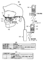
- FIG. 1 is a conceptual diagram according to one embodiment of the present disclosure.
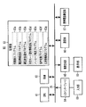
- FIG. 1 is a block diagram of a head mounted display according to an embodiment of the present disclosure.
- FIG. 2 is a block diagram of a mobile phone according to an embodiment of the present disclosure.
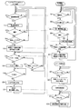
- FIG. It is a flowchart of each process of the present invention concerning one embodiment of this indication.
- FIG. 6 is a conceptual diagram according to another embodiment of the present disclosure. It is a block diagram of a head mount display concerning other embodiments of this indication.
- FIG. 10 is a block diagram of a mobile phone according to another embodiment of the present disclosure. It is a flowchart of each process of the present invention concerning other embodiments of this indication.
- HMD head mounted display
- a head-mounted display 100 includes a head-mounted display unit 50 that is worn on a user's head and a control unit 30 that is worn on a body such as the user's waist. It is configured.
- the head mounted display unit 50 includes a head mounting unit 51 and an image display unit 52.
- the head mounting portion 51 is in the shape of a frame of glasses, but may be in the shape of a helmet or the like, and includes anything that is structured to be mounted on the user's head. .
- the image display unit 52 is attached to the front side of the head mounting unit 51.
- the image display unit 52 generates an image and makes the user visually recognize the image.
- the image display unit 52 is configured by using a retinal scanning display that allows a user to visually recognize an image by directly scanning the user's eyeball with laser light.
- the image display unit 52 includes a half mirror 52a.
- the half mirror 52a reflects a part of the image light incident from the image display unit 52 and guides it to the left eye of the user.
- the half mirror 52a also transmits a part of the external light representing the external image and guides it to the left eye of the user.
- the image display unit 52 includes the half mirror 52a, the user can visually recognize the image generated by the image display unit 52 and can also visually recognize the outside world.
- the image display unit 52 may have a configuration using other devices such as a liquid crystal display and an organic EL (Organic Electroluminescence) display.
- the image display unit 52 is provided with an input unit 53 and an acceleration sensor 54 (shown in FIG. 2), each of which includes a plurality of buttons that accept input operations by the user.
- the control unit 30 is connected to the image display unit 52 and has a function of generating an image displayed by the image display unit 52.
- the control unit 30 has a function of communicating with the mobile phone 80 possessed by the user.
- the mobile phone 80 receives an incoming call ((1) in FIG. 1 (A))
- the mobile phone 80 transmits “phone information” of the communication partner to the control unit 30 ((A) in FIG. ) (2))
- the “telephone information” is displayed on the image display unit 52 ((3) in FIG. 1A).
- the control unit 30 transmits “standby mode notification information” to the mobile phone 80 ((4) in FIG. 1A), and the mobile phone 80 transmits “standby mode notification information” to the communication partner. It transmits to the telephone 90 ((5) of (A) of FIG.
- “standby mode” “phone information” of the mobile phone 90 is displayed on the image display unit 52 and a message transmitted from the mobile phone 90 and received by the mobile phone 80 is displayed on the image display unit 52.
- This mode is
- the communication partner who has confirmed the “standby mode notification information” transmits a “message” such as an email to the mobile phone 80 using the mobile phone 90
- the mobile phone 80 possessed by the user receives the “message”.
- the mobile phone 80 transmits the “message” to the control unit 30 ((7) in FIG. 1A).
- the control unit 30 displays the “message” on the image display unit 52 ((8) in FIG. 1A). For this reason, even when the hand cannot be released during a meeting, the user can easily check the “message” received by the mobile phone 80.
- the user who visually recognizes the “message” displayed on the image display unit 52 can respond to the “message” by operating the input unit 53 or moving his / her head.
- the control unit 30 When the user responds by operating the input unit 53, the control unit 30 generates “response information” corresponding to each button of the input unit 53, as shown in FIG.
- the acceleration sensor 54 detects the movement of the user's head and outputs a detection signal to the control unit 30, as shown in FIG.
- the control unit 30 generates “response information” based on the detection signal.
- the control unit 30 transmits the generated “response information” to the mobile phone 80 ((9) in FIG. 1A).
- the mobile phone 80 that has received the “response information” transmits the “response information” to the telephone 90 of the communication partner ((10) in FIG. 1A).
- the user can respond to the “message” transmitted from the telephone 90 of the communication partner with a simple input operation.
- the head mounted display 100 that realizes such a function will be described in detail.
- the head mounted display 100 will be described with reference to FIG.
- the control unit 30 includes a CPU 11, a RAM 12, a storage unit 13, an input interface 14, an image generation unit 15, and a communication unit 16. These components are connected to each other by a bus 9.
- the head mounted display unit 50 includes an input unit 53, an acceleration sensor 54, and an image display unit 52.
- the input unit 53 and the acceleration sensor 54 are connected to the input interface 14.
- the image display unit 52 is connected to the image generation unit 15.
- the connection between the components of the head mounted display unit 50 and the control unit 30 includes both wired and wireless connection methods.
- a CPU (abbreviation of central processing unit) 11 performs various calculations and processes in cooperation with a RAM (abbreviation of random access memory) 12 and a storage unit 13.
- the RAM 12 temporarily stores a program processed by the CPU 11 and data processed by the CPU 11 in its address space.
- the storage unit 13 includes an auxiliary storage device such as a nonvolatile memory or a hard disk.
- the storage unit 13 stores various programs and parameters for controlling the control unit 30. Various functions are realized by the various programs being processed by the CPU 11.
- the storage unit 13 stores a telephone information acquisition program 13a, a telephone information display program 13b, a standby mode setting program 13c, a message acquisition program 13d, a message display program 13e, a response information generation program 13f, and a standby mode determination program 13g. ing.
- the storage unit 13 has a telephone information storage area 13h, a standby mode flag storage area 13i, a message storage area 13j, and a response information table storage area 13k.
- the telephone information acquisition program 13a receives and acquires "phone information" of the communication partner transmitted from the mobile phone 80 via the communication unit 16, and stores the "phone information” in the telephone information storage area 13h. It is.
- the telephone information display program 13b is a program that outputs to the image generation unit 15 a drawing command for displaying the “telephone information” stored in the telephone information storage area 13h on the image display unit 52.
- the standby mode setting program 13c determines that the “standby mode setting signal” is input from the input interface 14 to the bus 9 by the user's input operation to the input unit 53.
- the “standby mode flag” is set. It is stored in the standby mode flag storage area 13i.
- the standby mode setting program 13c determines that the “standby mode release signal” is input from the input interface 14 to the bus 9 by the user's input operation to the input unit 53, the standby mode flag is stored.
- the “standby mode flag” is deleted from the area 13i.
- the standby mode setting program 13 c transmits “standby mode notification information” that the mobile phone 80 transfers to the mobile phone 90 to the mobile phone 80 via the communication unit 16.
- the message acquisition program 13d acquires the “message” transmitted from the mobile phone 90 and transferred from the mobile phone 80 via the communication unit 16, and stores it in the message storage area 13j.
- the message display program 13e outputs a drawing command for displaying the “message” stored in the message storage area 13j on the image display unit 52 to the image generation unit 15.
- the response information generation program 13f is a program that generates “response information” from an input operation by the user.
- the standby mode determination program 13g is a program that determines whether or not the standby mode is set. Specifically, the standby mode determination program 13g refers to the standby mode flag storage area 13i to determine whether or not the standby mode is in accordance with whether or not the “standby mode flag” is stored. to decide.
- the telephone information acquisition program 13a, the telephone information display program 13b, the standby mode setting program 13c, the message acquisition program 13d, the message display program 13e, the response information generation program 13f, and the standby mode determination program 13g are referred to as ASIC (Application Specific S Integrated i Circuit). ).
- the telephone information storage area 13h “telephone information” of the telephone 90 of the communication partner transmitted from the mobile phone 80 is stored.
- a “standby mode setting flag” is stored in the standby mode flag storage area 13i.
- the message storage area 13j “message” transmitted from the mobile phone 90 and transferred by the mobile phone 80 is stored.
- the response information table storage area 13k is a “response information” indicating a correspondence relationship between a plurality of input operations by the user and response information corresponding to the input operations. "Table" is stored.
- the input unit 53 receives an input operation from the user.
- the input unit 53 includes a physical button, a touch panel such as a matrix switch type or a capacitance type touch panel.
- a signal generated by an input operation by the user input unit 53 is converted in physical / logical format by the input interface 14 and output to the bus 9 as an input operation signal.
- the input unit 53 is provided in the image display unit 52, but may be provided in another head mounted display unit 50.
- the user can set and cancel the “standby mode” by operating the input unit 53. Further, the user can respond to the “message” transmitted from the telephone 90 of the communication partner by operating the input unit 53.
- the acceleration sensor 54 detects the motion of the user's head and the acceleration received by the image display unit 52.
- the acceleration detected by the acceleration sensor 54 is converted into a physical / logical format by the input interface 14 and input to the bus 9 as an input operation signal.
- the acceleration sensor 54 may be provided in the head mounting portion 51.
- the image generation unit 15 includes a GPU (Graphics Processing Unit) and a VRAM.
- the GPU generates “image data” in accordance with a drawing command from the telephone information display program 13b or the message display program 13e, and stores it in the VRAM.
- the “image data” stored in the VRAM is output to the image display unit 52 as an “image signal”.
- the communication unit 16 is a device that communicates with the mobile phone 80 possessed by the user.
- the communication unit 16 is a wireless standard interface based on infrared communication or Bluetooth (registered trademark).
- the mobile phone 80 includes a CPU 61, a RAM 62, a storage unit 63, an input interface 64, an image generation unit 65, a communication unit 66, and a mobile phone communication unit 67. These components are connected to each other by a bus 79.
- the cellular phone 80 further includes an input unit 68 and a display unit 69.
- the input unit 68 is connected to the input interface 64.
- the display unit 69 is connected to the image generation unit 65.
- CPU 61 performs various calculations and processes in cooperation with RAM 62 and storage unit 63.
- the RAM 62 temporarily stores programs processed by the CPU 61 and data processed by the CPU 61 in its address space.
- the storage unit 63 includes an auxiliary storage device such as a nonvolatile memory or a hard disk.
- the storage unit 63 stores various programs and parameters for controlling the mobile phone 80.
- the various programs are processed by the CPU 61 to realize various functions.
- the storage unit 63 stores an information display program 63a, a telephone information transmission program 63b, a call state notification program 63c, a standby mode notification information transmission program 63d, a message transfer program 63e, a voice conversion program 63f, and a response information transmission program 63g. ing.
- the information display program 63a is a program that outputs, to the image generation unit 65, a drawing command for displaying the owner name and telephone number of the telephone 90 of the communication partner on the display unit 69 when an incoming call is received.
- the telephone information transmission program 63b is a program for transmitting “telephone information” including the owner name and telephone number of the telephone 90 of the communication partner to the control unit 30 of the head mounted display 100 when there is an incoming call.
- the call state notification program 63c is a program that notifies the control unit 30 of the head mounted display 100 that the mobile phone 80 is in a call state with the telephone 90 of the communication partner.
- the standby mode notification information transmission program 63d is a program for transmitting “standby mode notification information” to the telephone 90 of the communication partner.
- the message transfer program 63e is a program for transferring the “message” transmitted from the telephone 90 of the communication partner to the control unit 30 of the head mounted display 100.
- the voice conversion program 63f is a program that converts a voice “message” transmitted from the telephone 90 of the communication partner into characters by voice recognition and generates a character “message”.
- the response information transmission program 63g is a program for transferring “response information” transmitted from the control unit 30 of the head mounted display 100 to the telephone 90 of the communication partner via the communication unit 66.
- the storage unit 63 stores a program for realizing a call function as a mobile phone and a mail transmission / reception function.
- the input unit 68 receives an input operation from the user.
- the input unit 68 includes a physical button, a touch panel such as a matrix switch type or a capacitance type touch panel.
- the signal generated by the input operation by the user input unit 68 is converted into a physical / logical format by the input interface 64 and output to the bus 79 as an “input operation signal”.
- the image generation unit 65 has a GPU and a VRAM.
- the GPU generates “image data” in accordance with a drawing command from the information display program 63a and stores it in the VRAM.
- the “image data” stored in the VRAM is output to the display unit 69 as an “image signal”.
- the communication unit 66 is a device that communicates with the communication unit 16 of the control unit 30.
- the communication unit 18 is an interface corresponding to the communication unit 16.
- the mobile phone communication unit 67 is a device that communicates with a wireless public communication network.
- the cellular phone communication unit 67 is an interface corresponding to the wireless public communication network.
- the public mobile phone communication unit 67 communicates with the telephone 90 of the communication partner via the wireless public communication network.
- Head mounted display main processing The head mounted display main process will be described with reference to FIG. When the power is turned on to the head mounted display 100 and the head mounted display main process is started, the process proceeds to S11.
- the telephone information acquisition program 13a determines whether or not the “telephone information” transmitted from the mobile phone 80 has been received. If the telephone information acquisition program 13a determines that “telephone information” has been received (YES in S11), the “telephone information” is stored in the telephone information storage area 13h, and the process proceeds to S12. . On the other hand, when the telephone information acquisition program 13a does not determine that “telephone information” has been received (NO in S11), the process does not proceed to S12.
- the telephone information display program 13b outputs to the image generation unit 15 a drawing command for displaying the “telephone information” stored in the telephone information storage area 13h on the image display unit 52.
- “Telephone information” including the name of the communication partner and the telephone number of the telephone 90 of the communication partner is displayed on the image display unit 52.
- the CPU 11 determines whether or not “call state information” has been received from the mobile phone 80. If the CPU 11 determines that “call state information” has been received from the mobile phone 80 (YES at S13), it is considered that the user is making a call using the mobile phone 80. Therefore, the CPU 11 returns to the determination process of S11 after outputting a drawing command for stopping the display of “telephone information” on the image display unit 52 to the image generation unit 15. On the other hand, if the CPU 11 determines that “call state information” has not been received within a predetermined time after receiving “phone information” from the mobile phone 80 in the determination process of S11 (determination process of S13). Is NO), the process proceeds to S14.
- the standby mode determination program 13g refers to the standby mode flag storage area 13i to determine whether or not the “standby mode flag” is stored. .
- the process proceeds to S15.
- the standby mode determination program 13g determines that the “standby mode flag” is not stored (NO in S14)
- the telephone information display program 13b reads “telephone information” in the image display unit 52. After outputting a drawing command for stopping the display to the image generation unit 15, the process returns to the determination process of S11.
- the user when the user does not wish to display a message on the image display unit 52, the user operates the input unit 53 to delete the “standby mode flag” from the standby mode flag storage area 13 i. By doing so, it is possible to prevent the “message” from being displayed on the image display unit 52.
- standby mode setting program 13c causes mobile phone 80 to transmit “standby mode notification information” via communication unit 16.
- the process of S15 ends, the process proceeds to the determination process of S16.
- the message acquisition program 13d determines whether or not a “message” is received from the mobile phone 80, and the “message” is stored in the telephone information storage area 13h. It is determined whether or not the information is transmitted from the same mobile phone as the “telephone information”.
- the message acquisition program 13d determines that the “message” is received from the mobile phone 90 of “phone information” stored in the phone information storage area 13h (YES in S16)
- the “message” Is stored in the message storage area 13j, and the process proceeds to S18.
- the message acquisition program 13d does not determine that “message” has been received from the mobile phone 90 of “phone information” stored in the phone information storage area 13h (NO in S16)
- S17 Proceed to the determination process.
- the standby mode determination program 13g determines whether or not the “standby mode flag” is stored in the standby mode flag storage area 13i. If the standby mode determination program 13g determines that the “standby mode flag” is stored in the standby mode flag storage area 13i (YES in S17), the process returns to the determination process in S16. On the other hand, when the standby mode determination program 13g determines that the “standby mode flag” is not stored in the standby mode flag storage area 13i (NO in S17), the image display unit 52 After outputting a drawing command for stopping the display of “telephone information” to the image generation unit 15, the process returns to the determination process of S11.
- the message display program 13e outputs to the image generation unit 15 a drawing command for displaying the “message” stored in the message storage area 13j on the image display unit 52.
- the “message” is displayed on the image display unit 52, and the user can confirm the “message”.
- the determination process of S16 only when it is determined that the message acquisition program 13d has received the “message” from the mobile phone 90 of “telephone information” stored in the telephone information storage area 13h, the “ “Message” is displayed on the image display unit 52. Therefore, since the “message” that is not related to the communication partner is not displayed on the image display unit 52, the user does not feel bothersome.
- the process of S18 ends, the process proceeds to the determination process of S19.
- the response information generation program 13f determines whether or not there is an input operation by the user. Specifically, when the user performs an input operation on the input unit 53 and the response information generation program 13f determines that an “input operation signal” is input from the input interface 14 to the bus 9, the user performs Judge that there was an input operation. Alternatively, when the user shakes his head or hits the image display unit 53 with his / her finger, the acceleration sensor 54 detects an acceleration of a predetermined value or more, and the response information generation program 13 f inputs “input” to the bus 9 from the input interface 14. If it is determined that the “operation signal” has been input, it is determined that there has been an input operation by the user.
- the process proceeds to S20. On the other hand, if the response information generation program 13f does not determine that there has been an input operation by the user (NO in S19), the process does not proceed to S20.
- the response information generation program 13f converts the input operation by the user into “response information” and generates it. Specifically, the response information generation program 13f is stored in the response information table storage area 13k and the “input operation signal” generated by the input operation performed on the input unit 53 in the determination process of S19. Corresponding to the “response information table” (shown in FIG. 1C), the “response information” corresponding to the “input operation signal” is specified. Alternatively, in the determination process of S19, when the user performs an input operation by shaking his / her head or hitting the image display unit 52, the response information generation program 13f generates an “input operation signal” generated by the input operation.
- the response information generation program 13f The “response information” generated in the process of S20 is transmitted to the mobile phone 80 possessed by the user via the communication unit 16.
- the message display program 13 e outputs a drawing command for stopping the display of “message” on the image display unit 52 to the image generation unit 15.
- the mobile phone main process will be described with reference to FIG.
- the mobile phone main process starts, and the process proceeds to the determination process of S51.
- the CPU 61 determines whether there is an incoming call from the mobile phone 90 or not. When the CPU 61 determines that there is an incoming call from the mobile phone 90 (YES in S51), the process proceeds to S52. On the other hand, when the CPU 61 does not determine that there is an incoming call from the mobile phone 90 (NO in the determination process in S51), the CPU 61 does not proceed to the determination process in S52.
- the CPU 61 determines whether or not communication with the control unit 30 of the head mounted display 100 is possible. When the CPU 61 determines that communication with the control unit 30 is possible (YES in S52), the process proceeds to S53. On the other hand, when the CPU 61 determines that communication with the control unit 30 is impossible (NO in S52), the process returns to S51.
- the phone information sending program 163b sends the “phone information” including the name of the communication partner and the phone number of the mobile phone 90 to the head mounted display 100 via the communication unit 66. It transmits to the control part 30.
- the process of S53 ends, the process proceeds to the determination process of S54.
- the CPU 61 determines whether or not the user has selected to make a call by operating the input unit 68. If the CPU 61 determines that it has selected to make a user call (YES in S54), the process proceeds to S55. On the other hand, when the user selects to hold the call by operating the operation unit 68, or when the user has not operated the operation unit 68 for a certain period of time, the CPU 61 confirms that the user makes a call. It is determined that no selection has been made (NO in S54), and the process proceeds to S56.
- the call status notification program 63c uses the communication unit 66 to head-mount the “call status information” indicating that the mobile phone 80 is in a call state with the mobile phone 90.
- the data is transmitted to the control unit 30 of the display 100.
- the standby mode notification information transmission program 63d transmits “standby mode notification information” to the communication partner's phone 90.
- the communication partner contact person
- the communication partner can perceive that the user (contacted person) is in a state where he / she cannot make a call by confirming the “standby mode notification information” with his / her mobile phone.
- the message standby process will be described with reference to FIG. When the power of the mobile phone 80 is turned on, the message standby process starts, and the process proceeds to the determination process of S61.
- the CPU 61 determines whether or not a “message” such as a mail has been received from the telephone 90 or the like of the communication partner. If the CPU 61 determines that a “message” has been received from the telephone 90 or the like of the communication partner (YES in S61), the process proceeds to S62. On the other hand, if the CPU 61 does not determine that a “message” has been received from the communication partner's telephone 90 or the like (NO in S61), the process does not proceed to S62.
- a “message” such as a mail has been received from the telephone 90 or the like of the communication partner.
- the message transfer program 63e transfers the “message” received in the determination process of S61 to the control unit 30 of the head mounted display 100.
- the voice conversion program 63f converts the voice “message” determined in S62 into a character by voice recognition. Then, the message transfer program 63e transfers the “message” converted to the character to the control unit 30 of the head mounted display 100.
- the process of S62 ends, the process returns to the determination process of S61.
- the response standby process will be described with reference to FIG.
- a response standby process starts, and the process proceeds to the determination process of S71.
- the CPU 61 determines whether or not “response information” has been received from the control unit 30 of the head mounted display 100.
- the CPU 61 determines that “response information” has been received from the control unit 30 of the head mounted display 100 (YES in the determination process in S71)
- the process proceeds to S72.
- the CPU 61 does not determine that “response information” has been received from the control unit 30 of the head mounted display 100 (NO in S71)
- the process does not proceed to S72.
- the response information transmission program 63g sends the “response information” received in the determination processing of S71 to the communication partner's phone 90 ( (Shown in (A) of FIG. 1). In this way, the communication partner can recognize the response by the user.
- the process of S72 ends, the process returns to the determination process of S71.
- a mobile phone system includes a mobile phone 180 possessed by a user and a head mounted display 200 that communicates with the mobile phone 180.
- the outline of the head mounted display 200 is the same as that of the head mounted display 100 according to the above-described one embodiment. Therefore, detailed description is omitted.
- the control unit 130 includes a CPU 111, a RAM 112, a storage unit 113, an input interface 114, an image generation unit 115, and a communication unit 116. These components are connected to each other by a bus 109.
- the head mounted display unit 150 includes an input unit 153, an acceleration sensor 154, and an image display unit 152. The input unit 153 and the acceleration sensor 154 are connected to the input interface 114.
- the image display unit 152 is connected to the image generation unit 115. Note that connection methods between the components of the head mounted display unit 150 and the control unit 130 include both wired and wireless connection methods.
- the CPU 111 performs various calculations and processes in cooperation with the RAM 112 and the storage unit 113.
- the RAM 112 temporarily stores a program processed by the CPU 111 and data processed by the CPU 111 in its address space.
- the storage unit 113 includes an auxiliary storage device such as a nonvolatile memory or a hard disk.
- the storage unit 113 stores various programs and parameters for controlling the control unit 130. The various programs are processed by the CPU 111 to realize various functions.
- the storage unit 113 stores a telephone information acquisition program 113a, a telephone information display program 113b, a message acquisition program 113c, a message display program 113d, and an input information transmission program 113e. Further, the storage unit 113 has a telephone information storage area 113f and a message storage area 113g.
- the telephone information acquisition program 113a receives and acquires the "telephone information of the communication partner transmitted from the mobile phone 180 possessed by the user" via the communication unit 116, and acquires the "telephone information” in the telephone information storage area 113f. It is a program to be memorized.
- the telephone information display program 113b is a program that outputs to the image generation unit 115 a drawing command for displaying the “telephone information” stored in the telephone information storage area 113f on the image display unit 152.
- the message acquisition program 113c acquires the “message” transmitted from the mobile phone 190 and transferred from the mobile phone 180 via the communication unit 116, and stores it in the message storage area 113g.
- the message display program 113 d outputs a drawing command for displaying the “message” stored in the message storage area 113 g on the image display unit 152 to the image generation unit 115.
- the input information transmission program 113e is a program for transmitting “input information” generated by a user input operation to the mobile phone 180 via the communication unit 116.
- the telephone information acquisition program 113a, the telephone information display program 113b, the message acquisition program 113c, the message display program 113d, and the input information transmission program 113e may be configured as an ASIC.
- the telephone information storage area 113f “telephone information” of the telephone 190 of the communication partner transmitted from the mobile phone 180 is stored.
- the message storage area 113g “message” transmitted from the mobile phone 190 and transferred by the mobile phone 180 is stored.
- the input unit 153 receives an input operation from the user.
- the input unit 153 includes a physical button, a touch panel such as a matrix switch type or a capacitance type touch panel.
- a signal generated by an input operation by the user input unit 153 is converted into a physical / logical format by the input interface 114 and output to the bus 109 as “input information”.
- the input unit 153 is provided in the image display unit 152, but may be provided in another head mounted display unit 150. The user can also set and cancel the “standby mode” by operating the input unit 153.
- a “standby mode setting signal” or a “standby mode release signal” is generated by the input interface 114, and the “standby mode setup signal” or “standby mode release signal” is generated. Is transmitted to the mobile phone 180 via the communication unit 116.
- the acceleration sensor 154 detects the motion of the user's head and the acceleration received by the image display unit 152.
- the acceleration detected by the acceleration sensor 154 is converted into a physical / logical format by the input interface 114 and input to the bus 109 as “input information”.
- the acceleration sensor 154 may be provided in the head mounting portion 151.
- the image generation unit 115 has a GPU and a VRAM.
- the GPU generates “image data” in accordance with a drawing command from the telephone information display program 113b or the message display program 113d and stores it in the VRAM.
- the “image data” stored in the VRAM is output to the image display unit 152 as an “image signal”.
- the communication unit 116 is a device that communicates with the mobile phone 180 possessed by the user.
- the communication unit 116 is a wireless standard interface based on infrared communication or Bluetooth (registered trademark).
- the mobile phone 180 includes a CPU 161, a RAM 162, a storage unit 163, an input interface 164, an image generation unit 165, an external communication unit 166, and a public network communication unit 167. These components are connected to each other via a bus 179.
- the cellular phone 180 further includes an input unit 168 and a display unit 169.
- the input unit 168 is connected to the input interface 164.
- the display unit 169 is connected to the image generation unit 165.
- the CPU 161 performs various calculations and processes in cooperation with the RAM 162 and the storage unit 163.
- the RAM 162 temporarily stores programs processed by the CPU 161 and data processed by the CPU 161 in its address space.
- the storage unit 163 includes an auxiliary storage device such as a nonvolatile memory or a hard disk.
- the storage unit 163 stores various programs and parameters for controlling the mobile phone 180. The various programs are processed by the CPU 161 to realize various functions.
- the storage unit 163 includes an external terminal display enablement confirmation program 163a, a telephone information acquisition program 163b, a telephone information transmission program 163c, a call state notification program 163d, a standby mode setting program 163e, a voice conversion program 163f, a message transfer program 163g, a response A program 163h is stored.
- the storage unit 163 stores a telephone information storage area 163j, a standby mode flag storage area 163k, a message storage area 163m, and a response information table storage area 163n.
- the external terminal display possibility check 163a is a program that determines whether or not the image display unit 152 is in a displayable state.
- the telephone information acquisition program 163b is a program that is acquired via the “telephone information” public network communication unit 167 including the name of the communication partner and the telephone number of the communication partner's telephone 190, and stores it in the telephone information storage area 163j.
- the telephone information transmission program 163c is a program for transmitting the “telephone information” to the control unit 130 of the head mounted display 200 via the external communication unit 166 when there is an incoming call.
- the call state notification program 163d transmits “call state information” indicating that the mobile phone 180 is in a call state with the communication partner telephone 190 to the control unit 130 of the head mounted display 200 via the external communication unit 166. It is.
- the standby mode setting program 163e determines that the “standby mode setting signal” is input from the input interface 164 to the bus 179 by the user's input operation to the input unit 168, the “standby mode flag” is set. It is stored in the standby mode flag storage area 163k.
- the standby mode setting program 163e determines that the “standby mode release signal” has been input from the input interface 164 to the bus 179 by the user's input operation to the input unit 168, the standby mode flag is stored.
- the “standby mode flag” is deleted from the area 163k.
- the standby mode setting program 163e receives the “standby mode setting signal” transmitted from the control unit 130 via the external communication unit 166. If the standby mode setting program 163e determines that the standby mode flag is stored, the standby mode flag storage area 163k stores the “standby mode flag”. Also, when the user operates the input unit 153 to determine that the standby mode setting program 163e has received the “standby mode release signal” transmitted from the control unit 130 via the external communication unit 166. The standby mode setting program 163e deletes the “standby mode flag” stored in the standby mode flag storage area 163k.
- the standby mode setting program 163e transmits “standby mode notification information” to the telephone 190 of the communication partner via the public network communication unit 167.
- the message transfer program 163g is a program for transferring a “message” transmitted from the telephone 190 of the communication partner stored in the message storage area 163m to the control unit 130 of the head mounted display 200.
- the voice conversion program 163f is a program that converts a voice “message” transmitted from the telephone 190 of the communication partner into a character by voice recognition and generates a character “message”.
- the response program 163h is a program that generates “response information” based on “input information” generated by an input operation by the user and transmitted from the control unit 130 via the external communication unit 166.
- the response program 163 h transmits the generated “response information” to the telephone 190 of the communication partner via the public network communication unit 167.
- the standby mode determination program 163i is a program that determines whether or not the standby mode is set. Specifically, the standby mode determination program 163i refers to the standby mode flag storage area 163k to determine whether or not the standby mode is in accordance with whether or not the “standby mode flag” is stored. to decide.
- the storage unit 163 stores a program for realizing a call function as a mobile phone and a mail transmission / reception function.
- External terminal display possibility confirmation program 163a telephone information acquisition program 163b, telephone information transmission program 163c, call state notification program 163d, standby mode setting program 163e, voice conversion program 163f, message transfer program 163g, response program 163h, standby mode
- the determination program 163i may be configured as an ASIC.
- the telephone information storage area 163j stores “telephone information” acquired by the telephone information acquisition program 163b.
- a “standby mode setting flag” is stored by the standby mode setting program 163e.
- the message storage area 163m a “message” transmitted from the mobile phone 190 is stored.
- the response information table storage area 163n is a “response information” indicating a correspondence relationship between a plurality of input operations by the user and response information corresponding to the input operations. "Table" is stored.
- the input unit 168 receives an input operation from the user.
- the input unit 168 includes a physical button, a touch panel such as a matrix switch type or a capacitance type touch panel.
- the signal generated by the input operation by the user input unit 168 is converted into a physical / logical format by the input interface 164 and output to the bus 179 as “input information”.
- the user can set and cancel the “standby mode” by operating the input unit 168. That is, when the user operates the input unit 168, a “standby mode setting signal” or a “standby mode release signal” is generated by the input interface 164, and the “standby mode set signal” or “standby mode release” is generated. Signal “is input to the bus 179.
- the image generation unit 165 has a GPU and a VRAM.
- the GPU generates “image data” in accordance with a drawing command from the CPU 161 and stores it in the VRAM.
- the “image data” stored in the VRAM is output to the display unit 169 as an “image signal”.
- the external communication unit 166 is a device that communicates with the communication unit 116 of the control unit 130.
- the communication unit 18 is an interface corresponding to the communication unit 116.
- the public network communication unit 167 is a device that communicates with the wireless public communication network.
- the public network communication unit 167 is an interface corresponding to the wireless public communication network.
- the public network communication unit 167 communicates with the communication partner telephone 190 via the wireless public communication network.
- the head mounted display main process will be described with reference to FIG.
- the process proceeds to the determination process of S111.
- the telephone information acquisition program 113a determines whether or not “telephone information” transmitted from the mobile phone 180 has been received. If the telephone information acquisition program 113a determines that “telephone information” has been received (YES in S111), the “telephone information” is stored in the telephone information storage area 113f, and the process proceeds to S112. . On the other hand, if the telephone information acquisition program 113a does not determine that “telephone information” has been received (NO in S111), the process does not proceed to S112.
- the telephone information display program 113b In the “telephone information display” process of S112, the telephone information display program 113b outputs a drawing command for displaying the “telephone information” stored in the telephone information storage area 113f on the image display unit 152 to the image generation unit 115. To do. “Telephone information” including the name of the communication partner and the telephone number of the telephone 190 of the communication partner is displayed on the image display unit 152.
- the process of S112 ends, the process proceeds to the determination process of S113.
- the CPU 111 determines whether or not “call state information” has been received from the mobile phone 180.
- CPU 111 determines that “call state information” has been received from mobile phone 180 (YES in S113)
- the CPU 111 determines that the “call state information” has not been received within a predetermined time after the “phone information” is received from the mobile phone 180 in the determination processing of S111 (the determination processing of S113). Is NO), the process proceeds to S114.
- the message acquisition program 113c determines whether or not a “message” is received from the mobile phone 180.
- the message acquisition program 113c determines that the “message” has been received from the mobile phone 190 (YES in the determination process in S114)
- the “message” is stored in the message storage area 113g, and the process proceeds to S115.
- the message acquisition program 113c does not determine that “message” has been received from the mobile phone 190 (NO in S114), the process does not proceed to S115.
- the message display program 113d outputs to the image generation unit 115 a drawing command for displaying the “message” stored in the message storage area 113g on the image display unit 152.
- the “message” is displayed on the image display unit 152, and the user can confirm the “message”.
- the process of S115 ends, the process proceeds to the determination process of S116.
- the CPU 111 determines whether or not there is an input operation by the user. Specifically, when the user performs an input operation to the input unit 153 and the CPU 111 determines that “input information” is input from the input interface 114 to the bus 109, the user performs an input operation. to decide. Alternatively, when the user shakes his head or hits the image display unit 153 with his / her finger, the acceleration sensor 154 detects an acceleration exceeding a predetermined value, and the CPU 111 inputs “input information” to the bus 109 from the input interface 114. If it is determined that the input operation has been performed, it is determined that the user has performed an input operation.
- the process proceeds to S117. On the other hand, if the CPU 111 does not determine that the user has performed an input operation (NO in S116), the process does not proceed to S117.
- the input information transmission program 113e sends the “input information” generated in the determination process of S116 to the mobile phone 180 possessed by the user via the communication unit 116. Send.
- the process of S117 ends, the process returns to the determination process of S111.
- the mobile phone main process will be described with reference to FIG.
- the mobile phone main process starts, and the process proceeds to the determination process of S151.
- the determination process of S151 “incoming call”, the CPU 161 determines whether there is an incoming call from the mobile phone 190.
- the telephone information acquisition program 163b includes the name of the communication partner and the telephone number of the communication partner's phone 190. "Telephone information" is acquired through the public network communication unit 167 and stored in the telephone information storage area 163j.
- the CPU 161 outputs a drawing command for displaying the “phone information” on the display unit 169 to the image generation unit 165. Thereafter, the CPU 161 advances the process to the determination process in S152. On the other hand, if the CPU 161 does not determine that there is an incoming call from the mobile phone 190 (NO in S151), the process does not proceed to S152.
- the external terminal display possibility confirmation program 163a determines whether the head mounted display 200 can display an image. Specifically, the external terminal display possibility confirmation program 163a determines whether or not communication with the control unit 130 of the head mounted display 200 is possible. When communication with the control unit 130 is possible, the external terminal display possibility confirmation program 163a determines whether or not the image display unit 152 is in an image displayable state via the control unit 130 (for example, the power source of the image display unit 152). Or not). If the external terminal display possibility confirmation program 163a determines that the head mounted display 200 can display an image (YES in S152), the process proceeds to S153. On the other hand, when the external terminal display possibility confirmation program 163a determines that the head mounted display 200 cannot display an image (NO in S152), the process returns to the determination process in S151.
- the telephone information transmission program 163c transmits the “telephone information” stored in the telephone information storage area 163j to the control unit of the head mounted display 200 via the external communication unit 166. To 130. When the process of S153 is completed, the process proceeds to the determination process of S154.
- the CPU 161 determines whether or not the user has selected to make a call by operating the input unit 168. When the CPU 161 determines that the user call is selected (YES in the determination process in S154), the CPU 161 proceeds to the process in S155. On the other hand, when the user selects to hold the call by operating the operation unit 168, or when the user has not operated the operation unit 168 for a certain period of time, the CPU 161 confirms that the user makes a call. It is determined that no selection has been made (NO in S154), and the process proceeds to S156.
- the call status notification program 163d transmits “call status information” indicating that the mobile phone 180 is in a call status with the mobile phone 190 to the control unit 130 of the head mounted display 200. Send to.
- the process of S155 ends, the process returns to the determination process of S151.
- standby mode determination program 163i refers to standby mode flag storage area 163k to determine whether “standby mode flag” is stored. . If the standby mode determination program 163i determines that the “standby mode flag” is stored (YES in S156), the process proceeds to S157. When the standby mode determination program 163i determines that the “standby mode flag” is not stored (NO in S156), the process returns to the determination process in S151.
- standby mode setting program 163e transmits “standby mode notification information” to communication partner phone 190.
- the communication partner contact person
- the communication partner can perceive that the user (contacted person) is in a state where he / she cannot make a call by confirming the “standby mode notification information” with the mobile phone 190 possessed by the communication partner (contact person).
- the process of S157 ends, the process returns to the determination process of S151.
- the message standby process will be described with reference to FIG.
- the message standby process starts, and the process proceeds to the determination process of S161.
- the CPU 161 determines whether or not a “message” such as a mail has been received from the same mobile phone 190 as the “phone information” stored in the telephone information storage area 163j.
- the CPU 161 determines that the “message” is received from the same mobile phone 190 as the “phone information” stored in the phone information storage area 163j (YES in S161)
- the “message” is The message is stored in the message storage area 163m, and the process proceeds to S162.
- the CPU 161 does not determine that the “message” is received from the same mobile phone 190 as the “phone information” stored in the phone information storage area 163j (NO in S161), the process proceeds to S162. Does not proceed.
- the CPU 161 determines whether the “message” received in the determination process of S161 is a voice. When the CPU 161 determines that the “message” received in the determination process of S161 is a voice (the determination process of S162 is YES), the process proceeds to S163. On the other hand, when the CPU 161 determines that the “message” received in the determination process of S161 is not a voice (the determination process of S162 is NO), the process proceeds to S164.
- the voice conversion program 163f converts the voice “message” determined in S162 into a character by voice recognition, and stores the “message” of the character in the message storage area 163m. .
- the process of S163 ends, the process proceeds to S164.
- the message transfer program 163g transfers the “message” stored in the message storage area 163m to the control unit 130 of the head mounted display 200.
- the process of S164 ends, the process returns to the determination process of S161.
- the CPU 161 determines in the determination process of S161 that the “message” is received from the same mobile phone 190 as the “phone information” stored in the telephone information storage area 163j.
- a “message” unrelated to the communication partner is displayed. Since it is not transmitted to the control unit 130 of the head mounted display 200, the user does not feel bothersome.
- the response standby process will be described with reference to FIG.
- a response standby process is started, and the process proceeds to the determination process of S171.
- the standby mode determination program 163i refers to the standby mode flag storage area 163k to determine whether or not the “standby mode flag” is stored. .
- the standby mode determination program 163i determines that the “standby mode flag” is stored (YES in S171), the process proceeds to S172. If the standby mode determination program 163i determines that the “standby mode flag” is not stored (NO in S171), the process does not proceed to S172.
- the CPU 161 determines whether or not “input information” has been received from the control unit 130 of the head mounted display 200 via the external communication unit 166. If the CPU 161 determines that “input information” has been received from the control unit 130 of the head mounted display 200 via the external communication unit 166 (YES in S172), the process proceeds to S173. On the other hand, if the CPU 161 does not determine that “input information” has been received from the control unit 130 of the head mounted display 200 via the external communication unit 166 (NO in S172), the process returns to the determination process in S171. .
- the response program 163h converts “input information” into “response information” and generates it. Specifically, in the determination process of S116 of the head mounted display main process, when the user performs an input operation on the input unit 153, the response program 163h includes “input information” generated by the input operation, The “response information table” (shown in FIG. 5C) stored in the response information table storage area 163n is associated to identify “response information” corresponding to the “input information”.
- the response program 163h displays the “input information” generated by the input operation and the response
- the “response information table” (shown in FIG. 5B) stored in the information table storage area 163n is associated to identify “response information” corresponding to the “input information”.
- the response program 163h sends the “response information” generated in the process of S173 via the public network communication unit 167 to the other party's telephone 190 (FIG. 5). (Shown in (A)). In this way, the communication partner can recognize the response by the user.
- the process of S174 ends, the process returns to the determination process of S171.
- the present invention has been described with respect to an example in which the communication partner's telephone is the mobile phone 90, but it goes without saying that the communication partner's telephone may be a fixed telephone.
Landscapes
- Health & Medical Sciences (AREA)
- Otolaryngology (AREA)
- Engineering & Computer Science (AREA)
- Signal Processing (AREA)
- Telephone Function (AREA)
Abstract
携帯電話と、この携帯電話と通信する外部端末とを備える携帯電話システムである。携帯電話は、外部端末と通信する外部通信部と、通信相手の電話と通信する公衆網通信部とを有する。外部端末は、画像表示部と、携帯電話の外部通信部と通信する通信部とを有する。携帯電話システムは、通信相手の電話情報が記憶される電話情報記憶手段と、通信相手の電話から着信したときに、通信相手の電話情報を電話情報記憶手段に記憶させる電話情報取得手段と、外部端末が表示可能な状態であるか否かを判断する外部端末表示可能確認手段と、外部端末が表示可能な状態である場合に、受信したメッセージを外部端末で表示可能な状態である待受モードに携帯電話があることを通知させる待受モード通知情報を生成し、通信相手の電話に送信する待受モード設定手段と、携帯電話がメッセージを受信した場合には、メッセージを画像表示部で表示させるメッセージ表示手段とを有する。
Description
本開示は、着信を受け取った人が通話できない場合であっても、着信内容の確認や連絡を行うことができるヘッドマウントディスプレイ、携帯電話及び携帯電話システムに関する。
従来、携帯電話を利用して、メール等のメッセージを送受信する技術が知られている。携帯電話は持ち運びが可能なため、携帯電話の所有者は、メッセージを受信したときに確認することができる。しかし、会議中等手が離せない場合には、携帯電話の所有者は受信したメッセージを確認することは困難で、通話することもできなかった。そこで、特許文献1には、腕時計型の表示装置に着信情報等を表示させる携帯端末システムが提案されている。
特許文献1に示される携帯端末システムでは、連絡を受けるユーザーが腕時計型の表示装置を見るために視線をそらす必要があり、会議中等手が離せない場合には前記表示装置に表示されたメッセージを確認することが困難であった。一方、ユーザーに対して連絡を行う相手(以下、連絡者)も、ユーザーがどのような状況にあるかが分からず、どのような連絡方法であればユーザーに対して連絡可能か分からなかった。本開示は、ユーザーが通話できない状態であっても携帯電話が受信したメッセージを簡単に確認することができ、連絡者がユーザーに適切な手段にて連絡を行うことができるヘッドマウントディスプレイ、携帯電話及び携帯電話システムを提供する。
本開示の1側面は、携帯電話と、この携帯電話と通信する外部端末とを備える携帯電話システムである。この携帯電話システムにおいて、前記携帯電話は、前記外部端末と通信する外部通信部と、無線公衆網を介して通信相手の電話と通信する公衆網通信部とを有し、前記外部端末は、画像が表示される画像表示部と、前記携帯電話の外部通信部と通信する通信部とを有する。そして、前記携帯電話システムは、前記通信相手の電話情報が記憶される電話情報記憶手段と、前記公衆網通信部が前記通信相手の電話から着信したときに、前記公衆網通信部を介して取得された通信相手の電話情報を、前記電話情報記憶手段に記憶させる電話情報取得手段と、前記外部端末が表示可能な状態であるか否かを判断する外部端末表示可能確認手段と、外部端末が表示可能な状態であると前記外部端末表示可能確認手段によって判断された場合に、前記公衆網通信部が受信したメッセージを前記外部端末で表示可能な状態である待受モードに前記携帯電話があることを通知させる待受モード通知情報を生成し、前記待受モード通知情報を、前記公衆網通信部を介して、前記通信相手の電話に送信する待受モード設定手段と、前記携帯電話が前記公衆網通信部を介して前記メッセージを受信した場合には、前記メッセージを、前記画像表示部で表示させるメッセージ表示手段とを有する。
これによれば、連絡者が連絡を携帯電話で行い、ユーザーが通話できない場合であっても、連絡者の携帯電話に前記待受モード通知情報が送信されるので、連絡者はユーザーが通話できない状態であることを知覚できる。そして、連絡者は携帯電話を用いてメッセージをユーザーが所持する携帯電話に送信し、そのメッセージはユーサーが視認する外部端末に送信されるので、連絡者がユーサーに連絡を行うことが可能となる。
また、前記携帯電話システムは、待受モードが設定されているか否かを判断する待受モード判断手段をさらに有し、前記待受モード設定手段は、前記携帯電話が待受モードであると前記待受モード判断手段によって判断された場合、前記待受モード通知情報を前記通信相手の電話に送信し、前記メッセージ表示手段は、前記携帯電話が待受モードであると前記待受モード判断手段によって判断された場合、前記メッセージを前記画像表示部で表示させてもよい。
これによれば、待受モードの場合に、メッセージが画像表示部で表示される。したがって、通話できない待受けモードの場合であっても、連絡者と意思疎通をすることが可能になる。
また、前記携帯電話システムは、前記携帯電話が待受けモードであるか否かを示す待受モードフラグが記憶される待受モードフラグ記憶手段をさらに有し、前記待受モード判断手段は、待受モードフラグ記憶領域に待受モードフラグが記憶されている場合に、前記携帯電話が待受モードであると判断してもよい。
これによれば、待受モードであるか否かの判断が、確実に行われる。
また、前記メッセージ表示手段は、前記公衆網通信部を介して前記携帯電話が受信した前記メッセージが、前記受信前記電話情報記憶手段に記憶されている前記電話情報と同一の電話から送信された場合、前記メッセージを前記画像表示部で表示させてもよい。
これによれば、連絡者と関係の無いメッセージが表示されることが無いので、ユーザーが煩わしく感じることが無い。
また、前記携帯電話システムは、ユーザーからの入力操作を検知する入力部と、前記待受モード判断手段によって待受モードであると判断された場合に、前記入力部によって検知されたユーザーの入力操作に基づき、前記メッセージに対する応答情報を生成し、前記応答情報を、前記公衆網通信部を介して前記通信相手の電話に送信する応答手段とをさらに有してもよい。
これによれば、ユーザーは、連絡者から送信されたメッセージに対する応答を行うことが可能となる。
また、前記携帯電話システムは、前記入力部によって検知されたユーザーの入力操作に基づく入力情報と前記応答情報との関係を表した応答情報テーブルが記憶される応答情報テーブル記憶手段をさらに有し、前記応答手段は、前記入力情報及び前記応答情報テーブルに基づき、前記応答情報を生成してもよい。
これによれば、会議中等手が離せない場合であっても、ユーザーは簡単な入力操作により、通信相手の電話から送信されたメッセージに対する応答を行うことが可能となる。
また、前記外部端末は、ユーザーの頭部に装着されることでユーザーに画像を視認させるヘッドマウントディスプレイであってもよい。
これによれば、ユーザーは表示部を手で保持する必要は無い。従って、ハンズフリーでメッセージの確認が行える。
本開示の他の側面は、ユーザーの頭部に装着され、ユーザーに画像を視認させる画像表示部と、ユーザーが所持する携帯電話と通信する通信手段と、通信相手の電話情報が記憶される電話情報記憶手段と、通信相手の電話情報を、前記通信手段を介して取得し、前記電話情報を前記電話情報記憶手段に記憶させる電話情報取得手段と、前記電話情報取得手段が、前記電話情報を取得した場合に、前記ユーザーが所持する携帯電話の通信相手の電話に、前記ユーザーが所持する携帯電話が受信したメッセージを前記画像表示部で表示可能な状態である待受モードであることを通知させる待受モード通知情報を生成し、前記待受モード通知情報を、前記通信手段を介して、前記ユーザーが所持する携帯電話に送信する待受モード設定手段と、前記ユーザーが所持する携帯電話が受信したメッセージを、前記通信手段を介して取得するメッセージ取得手段と、前記メッセージ取得手段が取得したメッセージを、前記画像表示部で表示させるメッセージ表示手段とを、有することを特徴とするヘッドマウントディスプレイである。
これによれば、待受モード設定手段は、待受モード情報を通信相手の電話に送信し、メッセージ取得手段は、ユーザーが所持する携帯電話が受信した前記通信相手の電話からのメッセージを取得し、画像表示部は前記メッセージを表示する。このため、会議中等手が離せない場合であっても、ユーザーは携帯電話が受信したメッセージを容易に確認することが可能となる。
また、前記待受モードが設定されているか否かを判断する待受モード判断手段をさらに有し、前記待受モード設定手段は、前記待受モードであると前記待受モード判断手段によって判断された場合に、前記待受モード通知情報をユーザーが所持する携帯電話に送信し、前記メッセージ表示手段は、前記待受モードであると前記待受モード判断手段によって判断された場合に、前記メッセージ取得手段が取得したメッセージを、前記画像表示部で表示させてもよい。
これによれば、ユーザーが画像表示部でメッセージを表示させることを希望する場合に限り、メッセージが画像表示部で表示されるので、ユーザーが煩わしく感じることが無い。
また、前記待受けモードであるか否かを示す待受モードフラグが記憶される待受モードフラグ記憶手段をさらに有し、前記待受モード判断手段は、前記待受モードフラグ記憶領域に前記待受モードフラグが記憶されている場合に、ユーザーが所持する携帯電話が待受モードであると判断してもよい。
これによれば、待受モード判断手段は、確実に待受モードであることを判断することができる。
また、前記メッセージ表示手段は、前記電話情報記憶手段に記憶されている前記電話情報と同一の電話から送信されたメッセージを前記画像表示部で表示させてもよい。
これによれば、通信相手と関係の無いメッセージが、画像表示部で表示されることが無いので、ユーザーが煩わしく感じることが無い。
また、ユーザーからの入力操作を検知する入力部と、前記入力部が検知したユーザーの入力操作に基づき、前記メッセージ取得手段が取得したメッセージに対する応答情報を生成し、前記応答情報を、前記通信手段を介してユーザーが所持する携帯電話に送信する応答情報生成手段とをさらに有してもよい。
これによれば、ユーザーは入力操作により、通信相手の電話から送信されたメッセージに対する応答を行うことが可能となる。
さらに、前記入力部によって検知されたユーザーの入力操作に基づく入力情報と前記応答情報との関係を表した応答情報テーブルが記憶される応答情報テーブル記憶手段を有し、応答情報生成手段は、入力部が検知したユーザーの入力操作及び前記応答情報テーブルに基づき、応答情報を生成してもよい。
これによれば、会議中等手が離せない場合であっても、ユーザーは簡単な入力操作により、通信相手の電話から送信されたメッセージに対する応答を行うことが可能となる。
本開示のさらに他の側面は、無線公衆網を介して他の電話と通信する公衆網通信部を有し、通話機能を有する携帯電話であって、表示機能を有する外部端末と通信する外部通信部と、通信相手の電話情報が記憶される電話情報記憶手段と、通信相手の電話情報を、前記公衆網通信部を介して取得し、前記電話情報を前記電話情報記憶手段に記憶させる電話情報取得手段と、前記公衆網通信部が通信相手の電話から着信したときに、前記電話情報取得手段が取得した前記通信相手の電話情報を、前記外部通信部を介して前記外部端末に送信する電話情報送信手段と、前記外部端末が表示可能な状態であるか否かを判断する外部端末表示可能確認手段と、前記外部端末表示可能確認手段が、外部端末が表示可能な状態であると判断した場合に、前記通信相手の電話に、前記公衆網通信部が受信したメッセージを前記外部端末で表示可能な状態である待受モードであることを通知させる待受モード通知情報を生成し、前記待受モード通知情報を、前記公衆網通信部を介して、前記通信相手の電話に送信する待受モード設定手段と、前記公衆網通信部がメッセージを受信した場合には、前記外部通信部を介して、前記メッセージを前記外部端末に送信するメッセージ転送手段を有すること特徴とする携帯電話である。
これによれば、待受モード設定手段は、待受モード通知情報を通信相手の電話に送信し、公衆網通信部が前記通信相手の電話からメッセージを受信した場合には、外部通信部を介して、前記メッセージを外部端末に送信する。このため、被連絡者が通話できない場合には、連絡者が所有する携帯電話に前記待受モード通知情報が送信されるので、連絡者は被連絡者が通話できない状態であることを知覚することができる。そして、連絡者は携帯電話を用いてメッセージを被連絡者の携帯電話に送信し、そのメッセージは被連絡者が視認する外部端末に送信されるので、連絡者が被連絡者に適切な手段で連絡を行うことが可能となる。
また、前記待受モードが設定されているか否かを判断する待受モード判断手段をさらに有し、前記待受モード設定手段は、前記待受モードであると前記待受モード判断手段によって判断された場合に、前記待受モード通知情報を通信相手の電話に送信し、前記メッセージ転送手段は、前記待受モードであると前記待受モード判断手段によって判断された場合に、前記公衆網通信部が受信したメッセージを、前記外部端末に送信してもよい。
これによれば、ユーザーが、携帯電話が受信したメッセージを外部端末に送信させることを希望する場合に限り、前記メッセージが外部端末に送信される。
また、前記待受けモードであるか否かを示す待受モードフラグが記憶される待受モードフラグ記憶手段をさらに有し、待受モード判断手段は、待受モードフラグ記憶領域に待受モードフラグが記憶されている場合に、ユーザーが所持する携帯電話が待受モードであると判断してもよい。
これによれば、待受モード判断手段は、確実に待受モードであることを判断することができる。
また、前記メッセージ転送手段は、前記電話情報記憶手段に記憶されている前記電話情報と同一の電話から送信されたメッセージに限り、前記メッセージを前記外部端末に送信してもよい。
これによれば、通信相手と関係の無いメッセージが、外部端末に送信されることが無いので、ユーザーが煩わしく感じることが無い。
また、前記待受モード判断手段によって待受モードであると判断され、且つ、前記外部通信部が前記外部端末から送信された入力情報を受信した場合に、前記入力情報に基づいて、前記公衆網通信部が受信したメッセージに対する応答情報を生成し、前記応答情報を、前記公衆網通信部を介して通信相手の電話に送信する応答手段をさらに有してもよい。
これによれば、ユーザーは、通信相手の電話から送信されたメッセージに対する応答を行うことが可能となる。
また、前記入力情報と前記応答情報との関係を表した応答情報テーブルが記憶される応答情報テーブル記憶手段をさらに有し、前記応答手段は、前記外部端末から送信された前記入力情報及び前記応答情報テーブルに基づき、前記応答情報を生成してもよい。
これによれば、会議中等手が離せない場合であっても、ユーザーは簡単な入力操作により、通信相手の電話から送信されたメッセージに対する応答を行うことが可能となる。
本開示によれば、ユーザーが通話できない状態であっても、携帯電話が受信したメッセージを簡単に確認することができ、連絡者がユーザーに適切な手段にて連絡を行うことができるヘッドマウントディスプレイ、携帯電話及び携帯電話システムが提供される。
(本開示の概要)
本開示を反映した実施形態について、図面を用いて以下に詳細に説明する。なお、本開示は、以下に記載の構成に限定されるものではなく、同一の技術的思想において種々の構成を採用することができる。例えば、以下に説明する各構成において、所定の構成を省略することができる。なお、本明細書において、HMDとは、ヘッドマウントディスプレイの略語である。
本開示を反映した実施形態について、図面を用いて以下に詳細に説明する。なお、本開示は、以下に記載の構成に限定されるものではなく、同一の技術的思想において種々の構成を採用することができる。例えば、以下に説明する各構成において、所定の構成を省略することができる。なお、本明細書において、HMDとは、ヘッドマウントディスプレイの略語である。
(1の実施形態)
図1に示されるように、1の実施形態に係るヘッドマウントディスプレイ100は、ユーザーの頭部に装着されるヘッドマウントディスプレイ部50と、ユーザーの腰等の身体に装着される制御部30とから構成されている。ヘッドマウントディスプレイ部50は、頭部装着部51と、画像表示部52とから構成されている。頭部装着部51は、図1に示される実施形態では、眼鏡のフレーム形状であるが、ヘルメット形状等であってもよく、ユーザーの頭部に装着される構造のものであれはすべて含まれる。
図1に示されるように、1の実施形態に係るヘッドマウントディスプレイ100は、ユーザーの頭部に装着されるヘッドマウントディスプレイ部50と、ユーザーの腰等の身体に装着される制御部30とから構成されている。ヘッドマウントディスプレイ部50は、頭部装着部51と、画像表示部52とから構成されている。頭部装着部51は、図1に示される実施形態では、眼鏡のフレーム形状であるが、ヘルメット形状等であってもよく、ユーザーの頭部に装着される構造のものであれはすべて含まれる。
画像表示部52は、頭部装着部51の側前部に取り付けられている。画像表示部52は、画像を生成し、当該画像をユーザーに視認させるものである。本実施形態では、画像表示部52は、レーザ光を直接ユーザーの眼球に走査することにより、ユーザーに画像を視認させる網膜走査型ディスプレイを用いて構成される。画像表示部52は、ハーフミラー52aを有する。ハーフミラー52aは、画像表示部52から入射された画像光の一部を反射し、ユーザーの左眼に導く。ハーフミラー52aはまた、外界像を表す外界光の一部を透過し、ユーザーの左眼に導く。このように、画像表示部52がハーフミラー52aを有するので、ユーザーは画像表示部52が生成する画像を視認することができると同時に、外界もまた視認することができる。なお、画像表示部52は、液晶ディスプレイ、有機EL(Organic Electroluminescence)ディスプレイなど、その他の装置を用いた構成であっても差し支えない。画像表示部52には、ユーザーによる入力操作を受け付ける複数のボタン等からなる入力部53や加速度センサー54(図2に示す)が設けられている。
制御部30は、画像表示部52と接続し、画像表示部52が表示する画像を生成する機能を有している。制御部30は、ユーザーが所持する携帯電話80と通信する機能を有している。本発明では、携帯電話80が着信した場合には(図1の(A)の(1))、携帯電話80は通信相手の「電話情報」を制御部30に送信し(図1の(A)の(2))、当該「電話情報」が画像表示部52で表示される(図1の(A)の(3))。次に、制御部30は「待受モード通知情報」を、携帯電話80に送信し(図1の(A)の(4))、携帯電話80は「待受モード通知情報」を通信相手の電話90に送信する(図1の(A)の(5))。なお、「待受モード」とは、画像表示部52で携帯電話90の「電話情報」が表示されるとともに、画像表示部52で携帯電話90から送信され携帯電話80で受信したメッセージが表示される状態のモードである。「待受モード通知情報」を確認した通信相手が、メール等の「メッセージ」を携帯電話90で携帯電話80に送信した場合において、ユーザーが所持する携帯電話80が、前記「メッセージ」を受信すると(図1の(A)の(6))、携帯電話80は当該「メッセージ」を制御部30に送信する(図1の(A)の(7))。「メッセージ」を受信した制御部30は、当該「メッセージ」を画像表示部52で表示させる(図1の(A)の(8))。このため、会議中等手が離せない場合であっても、ユーザーは携帯電話80が受信した「メッセージ」を簡単に確認することが可能となる。
画像表示部52で表示された「メッセージ」を視認したユーザーは、入力部53を操作したり、頭を動かしたりすることにより、前記「メッセージ」に対する応答を行うことができる。ユーザーが、入力部53を操作して応答する場合には、図1の(C)に示されるように、制御部30は入力部53の各ボタンに対応する「応答情報」を生成する。或いは、ユーザーが頭を動かす等により応答する場合には、加速度センサー54(図2参照)はユーザーの頭の動きを検知して検知信号を制御部30に出力し、図1の(B)に示されるように、制御部30は前記検知信号に基づいて「応答情報」を生成する。制御部30は、前記生成された「応答情報」を携帯電話80に送信する(図1の(A)の(9))。「応答情報」を受信した携帯電話80は、当該「応答情報」を通信相手の電話90に送信する(図1の(A)の(10))。このように、会議中等手が離せない場合であっても、ユーザーは簡単な入力操作により、通信相手の電話90から送信された「メッセージ」に対する応答をすることが可能となる。以下、このような機能を実現するヘッドマウントディスプレイ100について詳細に説明する。
(ヘッドマウントディスプレイのブロック図)
図2を用いて、ヘッドマウントディスプレイ100を説明する。制御部30は、CPU11、RAM12、記憶部13、入力インターフェース14、画像生成部15、通信部16を有している。これらの構成は、相互にバス9で接続されている。ヘッドマウントディスプレイ部50は、入力部53、加速度センサー54及び画像表示部52を有している。入力部53や加速度センサー54は、入力インターフェース14に接続している。画像表示部52は、画像生成部15に接続している。なお、ヘッドマウントディスプレイ部50と制御部30との各構成間の接続は、有線及び無線の両方の接続方式が含まれる。
図2を用いて、ヘッドマウントディスプレイ100を説明する。制御部30は、CPU11、RAM12、記憶部13、入力インターフェース14、画像生成部15、通信部16を有している。これらの構成は、相互にバス9で接続されている。ヘッドマウントディスプレイ部50は、入力部53、加速度センサー54及び画像表示部52を有している。入力部53や加速度センサー54は、入力インターフェース14に接続している。画像表示部52は、画像生成部15に接続している。なお、ヘッドマウントディスプレイ部50と制御部30との各構成間の接続は、有線及び無線の両方の接続方式が含まれる。
CPU(Central Processing Unitの略)11は、RAM(Random Access Memoryの略)12、記憶部13と協動して、各種演算、処理を行う。
RAM12は、CPU11で処理されるプログラムや、CPU11が処理するデータを、そのアドレス空間に一時的に記憶する。
記憶部13には、不揮発性メモリーやハードディスク等の補助記憶装置が含まれる。記憶部13には、制御部30を制御する各種プログラムやパラメータが記憶されている。当該各種プログラムが、CPU11で処理されることにより、各種機能を実現している。記憶部13には、電話情報取得プログラム13a、電話情報表示プログラム13b、待受モード設定プログラム13c、メッセージ取得プログラム13d、メッセージ表示プログラム13e、応答情報生成プログラム13f、待受モード判断プログラム13gが記憶されている。また、記憶部13には、電話情報記憶領域13h、待受モードフラグ記憶領域13i、メッセージ記憶領域13j、応答情報テーブル記憶領域13kを有している。
電話情報取得プログラム13aは、通信部16を介して、携帯電話80から送信された通信相手の「電話情報」を受信して取得し、当該「電話情報」を電話情報記憶領域13hに記憶させるプログラムである。
電話情報表示プログラム13bは、電話情報記憶領域13hに記憶された「電話情報」を画像表示部52で表示させる描画命令を画像生成部15に出力するプログラムである。
待受モード設定プログラム13cは、ユーザーの入力部53への入力操作により、「待受モード設定信号」が入力インターフェース14からバス9に入力されたと判断した場合には、「待受モードフラグ」を待受モードフラグ記憶領域13iに記憶させる。また、待受モード設定プログラム13cは、ユーザーの入力部53への入力操作により、「待受モード解除信号」が入力インターフェース14からバス9に入力されたと判断した場合には、待受モードフラグ記憶領域13iから「待受モードフラグ」を消去させる。待受モード設定プログラム13cは、携帯電話80が携帯電話90に転送する「待受モード通知情報」を、通信部16を介して、携帯電話80に送信する。
メッセージ取得プログラム13dは、携帯電話90から送信され、携帯電話80から転送された「メッセージ」を、通信部16を介して取得し、メッセージ記憶領域13jに記憶させる。
メッセージ表示プログラム13eは、メッセージ記憶領域13jに記憶された「メッセージ」を、画像表示部52に表示させる描画命令を画像生成部15に出力する。
応答情報生成プログラム13fは、ユーザーによる入力操作から、「応答情報」を生成するプログラムである。
待受モード判断プログラム13gは、待受モードであるか否かを判断するプログラムである。具体的には、待受モード判断プログラム13gは、待受モードフラグ記憶領域13iを参照することにより、「待受モードフラグ」が記憶されているか否かにより、待受モードであるか否かを判断する。
なお、電話情報取得プログラム13a、電話情報表示プログラム13b、待受モード設定プログラム13c、メッセージ取得プログラム13d、メッセージ表示プログラム13e、応答情報生成プログラム13f、待受モード判断プログラム13gを、ASIC(ApplicationSpecific Integrated Circuit)として構成することとしても差し支えない。
電話情報記憶領域13hには、携帯電話80から送信された通信相手の電話90の「電話情報」が記憶される。待受モードフラグ記憶領域13iには、「待受モード設定フラグ」が記憶される。
メッセージ記憶領域13jには、携帯電話90から送信され、携帯電話80によって転送された「メッセージ」が記憶される。応答情報テーブル記憶領域13kは、図1の(B)や(C)に示されるように、ユーザーによる複数の入力操作と、当該入力操作に対応した応答情報との対応関係を表した「応答情報テーブル」が記憶されている。
メッセージ記憶領域13jには、携帯電話90から送信され、携帯電話80によって転送された「メッセージ」が記憶される。応答情報テーブル記憶領域13kは、図1の(B)や(C)に示されるように、ユーザーによる複数の入力操作と、当該入力操作に対応した応答情報との対応関係を表した「応答情報テーブル」が記憶されている。
入力部53は、ユーザーからの入力操作を受け付けるものである。入力部53には、物理的なボタン、マトリックススイッチ式や静電容量式等のタッチパネルが含まれる。ユーザーの入力部53での入力操作により生成された信号は、入力インターフェース14で、物理的・論理的な形式が変換されて、入力操作信号としてバス9に出力される。図1に示される実施形態では、入力部53は、画像表示部52に設けられているが、他のヘッドマウントディスプレイ部50に設けられていても差し支えない。なお、ユーザーは、入力部53を操作することにより、「待受モード」の設定及び解除を行うことができる。また、ユーザーは、入力部53を操作することにより、通信相手の電話90から送信された「メッセージ」に対する応答を行うことが可能となる。
加速度センサー54は、ユーザーの頭の動作や、画像表示部52が受ける加速度を検出する。加速度センサー54が検出した加速度は、入力インターフェース14で、物理的・論理的な形式が変換されて、入力操作信号としてバス9に入力される。なお、加速度センサー54は、頭部装着部51に設けられていても差し支えない。
画像生成部15は、GPU(Graphics Processing Unit)及びVRAMを有している。GPUは、電話情報表示プログラム13bやメッセージ表示プログラム13eからの描画命令により、「画像データ」を生成し、VRAMに記憶させる。VRAMに記憶された「画像データ」は、「画像信号」として画像表示部52に出力される。
通信部16は、ユーザーが所持する携帯電話80と通信を行う装置である。通信部16は、赤外線通信やブルートゥース(登録商標)による無線規格のインターフェースとなっている。
(携帯電話のブロック図)
図3を用いて、以下に、携帯電話80について説明する。携帯電話80は、CPU61、RAM62、記憶部63、入力インターフェース64、画像生成部65、通信部66、携帯電話通信部67を有している。これらの構成は、相互にバス79で接続されている。携帯電話80は更に入力部68及び表示部69を有している。入力部68は、入力インターフェース64に接続している。表示部69は、画像生成部65に接続している。
図3を用いて、以下に、携帯電話80について説明する。携帯電話80は、CPU61、RAM62、記憶部63、入力インターフェース64、画像生成部65、通信部66、携帯電話通信部67を有している。これらの構成は、相互にバス79で接続されている。携帯電話80は更に入力部68及び表示部69を有している。入力部68は、入力インターフェース64に接続している。表示部69は、画像生成部65に接続している。
CPU61は、RAM62、記憶部63と協動して、各種演算、処理を行う。RAM62は、CPU61で処理されるプログラムや、CPU61が処理するデータを、そのアドレス空間に一時的に記憶する。
記憶部63には、不揮発性メモリーやハードディスク等の補助記憶装置が含まれる。記憶部63には、携帯電話80を制御する各種プログラムやパラメータが記憶されている。当該各種プログラムが、CPU61で処理されることにより、各種機能を実現している。
記憶部63には、情報表示プログラム63a、電話情報送信プログラム63b、通話状態通知プログラム63c、待受モード通知情報送信プログラム63d、メッセージ転送プログラム63e、音声変換プログラム63f、応答情報送信プログラム63gが記憶されている。
情報表示プログラム63aは、着信があった場合に、通信相手の電話90の所有者名や電話番号を表示部69で表示させる描画命令を、画像生成部65に出力するプログラムである。
電話情報送信プログラム63b、着信があった場合に、通信相手の電話90の所有者名や電話番号からなる「電話情報」を、ヘッドマウントディスプレイ100の制御部30に送信するプログラムである。
通話状態通知プログラム63cは、携帯電話80が通信相手の電話90と通話状態であることを、ヘッドマウントディスプレイ100の制御部30に通知するプログラムである。
待受モード通知情報送信プログラム63dは、「待受モード通知情報」を通信相手の電話90に送信するプログラムである。
メッセージ転送プログラム63eは、通信相手の電話90から送信された「メッセージ」をヘッドマウントディスプレイ100の制御部30に転送するプログラムである。
音声変換プログラム63fは、通信相手の電話90から送信された音声の「メッセージ」を音声認識により、文字に変換し、文字の「メッセージ」を生成するプログラムである。
応答情報送信プログラム63gは、ヘッドマウントディスプレイ100の制御部30から送信された「応答情報」を、通信部66を介して、通信相手の電話90に転送するプログラムである。
勿論、記憶部63には、携帯電話としての通話機能及びメール送受信機能を実現するプログラムが記憶されている。
入力部68は、ユーザーからの入力操作を受け付けるものである。入力部68には、物理的なボタン、マトリックススイッチ式や静電容量式等のタッチパネルが含まれる。ユーザーの入力部68での入力操作により生成された信号は、入力インターフェース64で、物理的・論理的な形式が変換されて、「入力操作信号」としてバス79に出力される。
画像生成部65は、GPU及びVRAMを有している。GPUは、情報表示プログラム63aからの描画命令により、「画像データ」を生成し、VRAMに記憶させる。VRAMに記憶された「画像データ」は、「画像信号」として表示部69に出力される。
通信部66は、制御部30の通信部16と通信を行う装置である。通信部18は、通信部16に対応したインターフェースとなっている。
携帯電話通信部67は、無線公衆通信網と通信を行う装置である。携帯電話通信部67は、前記無線公衆通信網に対応したインターフェースとなっている。本発明では、公携帯電話通信部67は、無線公衆通信網を介して、通信相手の電話90と通信する。
(ヘッドマウントディスプレイメイン処理)
図4を用いて、ヘッドマウントディスプレイメイン処理の説明をする。ヘッドマウントディスプレイ100に電源が投入されヘッドマウントディスプレイメイン処理が開始すると、S11の判断処理に進む。
図4を用いて、ヘッドマウントディスプレイメイン処理の説明をする。ヘッドマウントディスプレイ100に電源が投入されヘッドマウントディスプレイメイン処理が開始すると、S11の判断処理に進む。
S11「電話情報受信」の判断処理において、電話情報取得プログラム13aは、携帯電話80から送信された「電話情報」を受信したか否かを判断する。電話情報取得プログラム13aが、「電話情報」を受信したと判断した場合には(S11の判断処理がYES)、当該「電話情報」を電話情報記憶領域13hに記憶させて、S12の処理に進む。一方で、電話情報取得プログラム13aが、「電話情報」を受信したと判断しない場合には(S11の判断処理がNO)、S12の処理に進まない。
S12の「電話情報表示」の処理において、電話情報表示プログラム13bは、電話情報記憶領域13hに記憶されている「電話情報」を画像表示部52で表示させる描画命令を、画像生成部15に出力する。通信相手の名前や通信相手の電話90の電話番号からなる「電話情報」は、画像表示部52で表示される。S12の処理が終了すると、S13の判断処理に進む。
S13「通話」の判断処理において、CPU11は、携帯電話80から「通話状態情報」を受信したか否かを判断する。CPU11が、携帯電話80から「通話状態情報」を受信したと判断した場合には(S13の判断処理がYES)、ユーザーが携帯電話80を用いて通話を行っていると考えられる。そのため、CPU11は、画像表示部52における「電話情報」の表示を停止させる描画命令を画像生成部15に出力した後に、S11の判断処理に戻る。一方で、CPU11が、「通話状態情報」を、S11の判断処理で携帯電話80から「電話情報」を受信してから所定時間の内に受信しなかったと判断した場合には(S13の判断処理がNO)、S14の判断処理に進む。
S14「待受モードフラグ有り」の判断処理において、待受モード判断プログラム13gは、待受モードフラグ記憶領域13iを参照することにより、「待受モードフラグ」が記憶されているか否かを判断する。待受モード判断プログラム13gが、「待受モードフラグ」が記憶されていると判断した場合には(S14の判断処理がYES)、S15の処理に進む。待受モード判断プログラム13gが、「待受モードフラグ」が記憶されていないと判断した場合には(S14の判断処理がNO)、電話情報表示プログラム13bは、画像表示部52における「電話情報」の表示を停止させる描画命令を画像生成部15に出力した後に、S11の判断処理に戻る。このように、ユーザーが画像表示部52でメッセージを表示させることを希望しない場合には、ユーザーが入力部53を操作することにより、「待受モードフラグ」を待受モードフラグ記憶領域13iから消去させることにより、「メッセージ」を画像表示部52で表示させないようにすることができる。
S15「待受モード通知情報を携帯電話に送信」の処理において、待受モード設定プログラム13cは、「待受モード通知情報」を、通信部16を介して、携帯電話80に送信させる。S15の処理が終了すると、S16の判断処理に進む。
S16「メッセージ受信」の判断処理において、メッセージ取得プログラム13dは、携帯電話80から「メッセージ」を受信したか否かを判断し、さらに、当該「メッセージ」が電話情報記憶領域13hに記憶されている「電話情報」と同一の携帯電話から送信されたものであるか否かを判断する。メッセージ取得プログラム13dが、電話情報記憶領域13hに記憶されている「電話情報」の携帯電話90から「メッセージ」を受信したと判断した場合には(S16の判断処理がYES)、当該「メッセージ」をメッセージ記憶領域13jに記憶させて、S18の処理に進む。一方で、メッセージ取得プログラム13dが、電話情報記憶領域13hに記憶されている「電話情報」の携帯電話90から「メッセージ」を受信したと判断しない場合には(S16の判断処理がNO)、S17の判断処理に進む。
S17「待受モードフラグ有り」の判断処理において、待受モード判断プログラム13gは、待受モードフラグ記憶領域13iに「待受モードフラグ」が記憶されているか否かを判断する。待受モード判断プログラム13gが、待受モードフラグ記憶領域13iに「待受モードフラグ」が記憶されていると判断した場合には(S17の判断処理がYES)、S16の判断処理に戻る。一方で、待受モード判断プログラム13gが、待受モードフラグ記憶領域13iに「待受モードフラグ」が記憶されていないと判断した場合には(S17の判断処理がNO)、画像表示部52における「電話情報」の表示を停止させる描画命令を画像生成部15に出力した後に、S11の判断処理に戻る。
S18「メッセージを表示」の処理において、メッセージ表示プログラム13eは、メッセージ記憶領域13jに記憶されている「メッセージ」を画像表示部52で表示させる描画命令を、画像生成部15に出力する。前記「メッセージ」は画像表示部52で表示され、ユーザーは、前記「メッセージ」を確認することができる。このように、S16の判断処理において、メッセージ取得プログラム13dが、電話情報記憶領域13hに記憶されている「電話情報」の携帯電話90から「メッセージ」を受信したと判断した場合に限り、前記「メッセージ」が画像表示部52に表示される。従って、通信相手と関係の無い「メッセージ」が、画像表示部52で表示されることが無いので、ユーザーが煩わしく感じることが無い。S18の処理が終了すると、S19の判断処理に進む。
S19「入力あり」の判断処理において、応答情報生成プログラム13fは、ユーザーによる入力操作があったか否かを判断する。具体的には、ユーザーが入力部53への入力操作を行うことにより、応答情報生成プログラム13fが、入力インターフェース14からバス9に「入力操作信号」が入力されたと判断した場合には、ユーザーによる入力操作があったと判断する。或いは、ユーザーが頭を振ったり、画像表示部53を指で叩いたりして、加速度センサー54が所定値以上の加速度を検知し、応答情報生成プログラム13fが、入力インターフェース14からバス9に「入力操作信号」が入力されたと判断した場合には、ユーザーによる入力操作があったと判断する。応答情報生成プログラム13fが、ユーザーによる入力操作があったと判断した場合には(S19の判断処理がYES)、S20の処理に進む。一方で、応答情報生成プログラム13fが、ユーザーによる入力操作があったと判断しない場合には(S19の判断処理がNO)、S20の処理には進まない。
S20「入力を応答に変換」の処理において、応答情報生成プログラム13fは、ユーザーによる入力操作を「応答情報」に変換して生成する。具体的には、応答情報生成プログラム13fは、S19の判断処理において入力部53に対して行われた入力操作によって生成された「入力操作信号」と、応答情報テーブル記憶領域13kに記憶されている「応答情報テーブル」(図1の(C)に示す)を対応させて、前記「入力操作信号」に対応する「応答情報」特定する。或いは、S19の判断処理において、ユーザーが頭を振る若しくは画像表示部52を叩くことによる入力操作を行った場合には、応答情報生成プログラム13fは、前記入力操作によって生成された「入力操作信号」と、応答情報テーブル記憶領域13kに記憶されている「応答情報テーブル」(図1の(B)に示す)を対応させて、前記「入力操作信号」に対応する「応答情報」特定する。S20の処理が終了すると、S21の処理に進む。
S21「応答を携帯電話に送信」の処理において、応答情報生成プログラム13fは、
S20の処理で生成された「応答情報」を、通信部16を介して、ユーザーが所持する携帯電話80に送信する。メッセージ表示プログラム13eは、画像表示部52における「メッセージ」の表示を停止させる描画命令を画像生成部15に出力する。S21の処理が終了すると、S11の判断処理に戻る。
S20の処理で生成された「応答情報」を、通信部16を介して、ユーザーが所持する携帯電話80に送信する。メッセージ表示プログラム13eは、画像表示部52における「メッセージ」の表示を停止させる描画命令を画像生成部15に出力する。S21の処理が終了すると、S11の判断処理に戻る。
(携帯電話メイン処理)
図4を用いて、携帯電話メイン処理の説明をする。携帯電話80に電源が投入されると、携帯電話メイン処理が開始し、S51の判断処理に進む。
図4を用いて、携帯電話メイン処理の説明をする。携帯電話80に電源が投入されると、携帯電話メイン処理が開始し、S51の判断処理に進む。
S51「着信有り」の判断処理において、CPU61は、携帯電話90からの着信が有ったか否かを判断する。CPU61が、携帯電話90からの着信が有ったと判断した場合には(S51の判断処理がYES)、S52の判断処理に進む。一方で、CPU61が、携帯電話90からの着信が有ったと判断しない場合には(S51の判断処理がNO)、S52の判断処理に進まない。
S52「HMDと通信可」の判断処理において、CPU61は、ヘッドマウントディスプレイ100の制御部30と通信可能であるか否かを判断する。CPU61が、制御部30と通信可能であると判断した場合には(S52の判断処理がYES)、S53の処理に進む。一方で、CPU61が、制御部30と通信不能であると判断した場合には(S52の判断処理がNO)、S51の判断処理に戻る。
S53「HMDに電話情報送信」の処理において、電話情報送信プログラム163bは、通信相手の名前や携帯電話90の電話番号からなる「電話情報」を、通信部66を介して、ヘッドマウントディスプレイ100の制御部30に送信する。S53の処理が終了すると、S54の判断処理に進む。
S54「通話」の判断処理において、CPU61は、ユーザーが入力部68を操作することにより通話することを選択したか否かを判断する。CPU61は、ユーザー通話することを選択したと判断した場合には(S54の判断処理がYES)、S55の処理に進む。一方で、ユーザーが操作部68を操作することにより通話を保留することを選択した場合、或いは、ユーザーが一定時間以上操作部68を操作しなかった場合には、CPU61はユーザーが通話することを選択しなかったと判断し(S54の判断処理がNO)、S56の判断処理に進む。
S55の「HMDに通話状態通知」の処理において、通話状態通知プログラム63cは、携帯電話80が携帯電話90と通話状態であることを表す「通話状態情報」を、通信部66を介してヘッドマウントディスプレイ100の制御部30に送信する。S55の処理が終了すると、S51の判断処理に戻る。
S56「待受モード通知情報受信」の判断処理において、CPU61が、「待受モード通信情報」を受信したと判断した場合には(S56の判断処理がYES)、S57の処理に進む。一方で、CPU61が、「待受モード通信情報」を、一定時間以上受信していないと判断した場合には(S56の判断処理がNO)、S51の判断処理に戻る。
S57「待受モード通知情報を通信相手の電話に送信」の処理において、待受モード通知情報送信プログラム63dは、「待受モード通知情報」を通信相手の電話90に送信する。通信相手(連絡者)は、「待受モード通知情報」を自己が所持する携帯電話で確認することにより、ユーザー(被連絡者)が通話できない状態であることを知覚することができる。S57の処理が終了すると、S51の判断処理に戻る。
(メッセージ待受処理)
図4を用いて、メッセージ待受処理について説明する。携帯電話80の電源が投入されると、メッセージ待受処理が開始し、S61の判断処理に進む。
図4を用いて、メッセージ待受処理について説明する。携帯電話80の電源が投入されると、メッセージ待受処理が開始し、S61の判断処理に進む。
S61「メッセージあり」の判断処理において、CPU61は、通信相手の電話90等からメール等の「メッセージ」を受信したか否かを判断する。CPU61が、通信相手の電話90等から「メッセージ」を受信したと判断した場合には(S61の判断処理がYES)、S62の処理に進む。一方で、CPU61が、通信相手の電話90等から「メッセージ」を受信したと判断しない場合には(S61の判断処理がNO)、S62の処理に進まない。
S62「受信したメッセージをHMDに転送」に処理において、メッセージ転送プログラム63eは、S61の判断処理で受信した「メッセージ」をヘッドマウントディスプレイ100の制御部30に転送する。なお、前記「メッセージ」が音声である場合には、音声変換プログラム63fは、S62の判断処理した音声の「メッセージ」を、音声認識により文字に変換する。そして、メッセージ転送プログラム63eは、前記文字に変換された「メッセージ」をヘッドマウントディスプレイ100の制御部30に転送する。S62の処理が終了すると、S61の判断処理に戻る。
(応答待受処理)
図4を用いて、応答待受処理について説明する。携帯電話80の電源が投入されると、応答待受処理が開始し、S71の判断処理に進む。
図4を用いて、応答待受処理について説明する。携帯電話80の電源が投入されると、応答待受処理が開始し、S71の判断処理に進む。
S71「応答受信」の判断処理の処理において、CPU61は、ヘッドマウントディスプレイ100の制御部30から「応答情報」を受信したか否かを判断する。CPU61が、ヘッドマウントディスプレイ100の制御部30から「応答情報」を受信したと判断した場合には(S71の判断処理がYES)S72の処理に進む。一方で、CPU61が、ヘッドマウントディスプレイ100の制御部30から「応答情報」を受信したと判断しない場合には(S71の判断処理がNO)S72の処理に進まない。
S72「応答を通信相手の電話に送信」の処理において、応答情報送信プログラム63gは、S71の判断処理で受信した「応答情報」を、携帯電話通信部67を介して、通信相手の電話90(図1の(A)に示す)に送信する。このようにして、通信相手は、ユーザーによる応答を認知することができる。S72の処理が終了すると、S71の判断処理に戻る。
(他の実施形態)
図5に示されるように、他の実施形態に係る携帯電話システムは、ユーザーが所持する携帯電話180と、この携帯電話180と通信するヘッドマウントディスプレイ200とから構成されている。ヘッドマウントディスプレイ200の概要は、前記した1の実施形態に係るヘッドマウントディスプレイ100と同様である。そのため、詳細な説明は省略される。
図5に示されるように、他の実施形態に係る携帯電話システムは、ユーザーが所持する携帯電話180と、この携帯電話180と通信するヘッドマウントディスプレイ200とから構成されている。ヘッドマウントディスプレイ200の概要は、前記した1の実施形態に係るヘッドマウントディスプレイ100と同様である。そのため、詳細な説明は省略される。
(ヘッドマウントディスプレイのブロック図)
図6を用いて、ヘッドマウントディスプレイ200を説明する。制御部130は、CPU111、RAM112、記憶部113、入力インターフェース114、画像生成部115、通信部116を有している。これらの構成は、相互にバス109で接続されている。ヘッドマウントディスプレイ部150は、入力部153、加速度センサー154及び画像表示部152を有している。入力部153や加速度センサー154は、入力インターフェース114に接続している。画像表示部152は、画像生成部115に接続している。なお、ヘッドマウントディスプレイ部150と制御部130との各構成間の接続方式には、有線及び無線の両方の接続方式が含まれる。
図6を用いて、ヘッドマウントディスプレイ200を説明する。制御部130は、CPU111、RAM112、記憶部113、入力インターフェース114、画像生成部115、通信部116を有している。これらの構成は、相互にバス109で接続されている。ヘッドマウントディスプレイ部150は、入力部153、加速度センサー154及び画像表示部152を有している。入力部153や加速度センサー154は、入力インターフェース114に接続している。画像表示部152は、画像生成部115に接続している。なお、ヘッドマウントディスプレイ部150と制御部130との各構成間の接続方式には、有線及び無線の両方の接続方式が含まれる。
CPU111は、RAM112、記憶部113と協動して、各種演算、処理を行う。
RAM112は、CPU111で処理されるプログラムや、CPU111が処理するデータを、そのアドレス空間に一時的に記憶する。
記憶部113には、不揮発性メモリーやハードディスク等の補助記憶装置が含まれる。記憶部113には、制御部130を制御する各種プログラムやパラメータが記憶されている。当該各種プログラムが、CPU111で処理されることにより、各種機能を実現している。記憶部113には、電話情報取得プログラム113a、電話情報表示プログラム113b、メッセージ取得プログラム113c、メッセージ表示プログラム113d、入力情報送信プログラム113eが記憶されている。また、記憶部113には、電話情報記憶領域113f、メッセージ記憶領域113gを有している。
電話情報取得プログラム113aは、通信部116を介して、ユーザーが所持する携帯電話180から送信された通信相手の電話情報」を受信して取得し、当該「電話情報」を電話情報記憶領域113fに記憶させるプログラムである。電話情報表示プログラム113bは、電話情報記憶領域113fに記憶された「電話情報」を画像表示部152で表示させる描画命令を画像生成部115に出力するプログラムである。メッセージ取得プログラム113cは、携帯電話190から送信され、携帯電話180から転送された「メッセージ」を、通信部116を介して取得し、メッセージ記憶領域113gに記憶させる。メッセージ表示プログラム113dは、メッセージ記憶領域113gに記憶された「メッセージ」を、画像表示部152に表示させる描画命令を画像生成部115に出力する。入力情報送信プログラム113eは、ユーザーの入力操作により生成された「入力情報」を、通信部116を介して、携帯電話180に送信するプログラムである。なお、電話情報取得プログラム113a、電話情報表示プログラム113b、メッセージ取得プログラム113c、メッセージ表示プログラム113d、入力情報送信プログラム113eを、ASICとして構成することとしても差し支えない。
電話情報記憶領域113fには、携帯電話180から送信された通信相手の電話190の「電話情報」が記憶される。
メッセージ記憶領域113gには、携帯電話190から送信され、携帯電話180によって転送された「メッセージ」が記憶される。
メッセージ記憶領域113gには、携帯電話190から送信され、携帯電話180によって転送された「メッセージ」が記憶される。
入力部153は、ユーザーからの入力操作を受け付けるものである。入力部153には、物理的なボタン、マトリックススイッチ式や静電容量式等のタッチパネルが含まれる。ユーザーの入力部153での入力操作により生成された信号は、入力インターフェース114で、物理的・論理的な形式が変換されて、「入力情報」としてバス109に出力される。図5に示される実施形態では、入力部153は、画像表示部152に設けられているが、他のヘッドマウントディスプレイ部150に設けられていても差し支えない。なお、ユーザーは入力部153を操作することにより、「待受モード」の設定及び解除を行うこともできる。つまり、ユーザーが入力部153を操作すると、入力インターフェース114で「待受モード設定信号」又は「待受モード解除信号」を生成され、当該「待受モード設定信号」又は「待受モード解除信号」が通信部116を介して携帯電話180に送信される。
加速度センサー154は、ユーザーの頭の動作や、画像表示部152が受ける加速度を検出する。加速度センサー154が検出した加速度は、入力インターフェース114で、物理的・論理的な形式が変換されて、「入力情報」としてバス109に入力される。なお、加速度センサー154は、頭部装着部151に設けられていても差し支えない。
画像生成部115は、GPU及びVRAMを有している。GPUは、電話情報表示プログラム113bやメッセージ表示プログラム113dからの描画命令により、「画像データ」を生成し、VRAMに記憶させる。VRAMに記憶された「画像データ」は、「画像信号」として画像表示部152に出力される。
通信部116は、ユーザーが所持する携帯電話180と通信を行う装置である。通信部116は、赤外線通信やブルートゥース(登録商標)による無線規格のインターフェースとなっている。
(携帯電話のブロック図)
図7を用いて、以下に、携帯電話180について説明する。携帯電話180は、CPU161、RAM162、記憶部163、入力インターフェース164、画像生成部165、外部通信部166、公衆網通信部167を有している。これらの構成は、相互にバス179で接続されている。携帯電話180は更に入力部168及び表示部169を有している。入力部168は、入力インターフェース164に接続している。表示部169は、画像生成部165に接続している。
図7を用いて、以下に、携帯電話180について説明する。携帯電話180は、CPU161、RAM162、記憶部163、入力インターフェース164、画像生成部165、外部通信部166、公衆網通信部167を有している。これらの構成は、相互にバス179で接続されている。携帯電話180は更に入力部168及び表示部169を有している。入力部168は、入力インターフェース164に接続している。表示部169は、画像生成部165に接続している。
CPU161は、RAM162、記憶部163と協動して、各種演算、処理を行う。RAM162は、CPU161で処理されるプログラムや、CPU161が処理するデータを、そのアドレス空間に一時的に記憶する。
記憶部163には、不揮発性メモリーやハードディスク等の補助記憶装置が含まれる。記憶部163には、携帯電話180を制御する各種プログラムやパラメータが記憶されている。当該各種プログラムが、CPU161で処理されることにより、各種機能を実現している。記憶部163には、外部端末表示可能確認プログラム163a、電話情報取得プログラム163b、電話情報送信プログラム163c、通話状態通知プログラム163d、待受モード設定プログラム163e、音声変換プログラム163f、メッセージ転送プログラム163g、応答プログラム163hが記憶されている。また、記憶部163には、電話情報記憶領域163j、待受モードフラグ記憶領域163k、メッセージ記憶領域163m、応答情報テーブル記憶領域163nが記憶されている。
外部端末表示可能確認163aは、画像表示部152が表示可能な状態であるか否かを判断するプログラムである。電話情報取得プログラム163bは、通信相手の名前や通信相手の電話190の電話番号からなる「電話情報」公衆網通信部167を介して取得し、電話情報記憶領域163jに記憶させるプログラムである。電話情報送信プログラム163c、着信があった場合に、前記「電話情報」を、外部通信部166を介してヘッドマウントディスプレイ200の制御部130に送信するプログラムである。通話状態通知プログラム163dは、携帯電話180が通信相手の電話190と通話状態であることを表す「通話状態情報」を、外部通信部166を介してヘッドマウントディスプレイ200の制御部130に送信するプログラムである。待受モード設定プログラム163eは、ユーザーの入力部168への入力操作により、「待受モード設定信号」が入力インターフェース164からバス179に入力されたと判断した場合には、「待受モードフラグ」を待受モードフラグ記憶領域163kに記憶させる。また、待受モード設定プログラム163eは、ユーザーの入力部168への入力操作により、「待受モード解除信号」が入力インターフェース164からバス179に入力されたと判断した場合には、待受モードフラグ記憶領域163kから「待受モードフラグ」を消去させる。或いは、ユーザーがヘッドマウントディスプレイ部150の入力部153を操作することにより、待受モード設定プログラム163eが制御部130から送信された「待受モード設定信号」を、外部通信部166を介して受信したと判断した場合には、待受モード設定プログラム163eは、「待受モードフラグ」を待受モードフラグ記憶領域163kに記憶させる。また、ユーザーが入力部153を操作することにより、待受モード設定プログラム163eが制御部130から送信された「待受モード解除信号」を、外部通信部166を介して受信したと判断した場合には、待受モード設定プログラム163eは、待受モードフラグ記憶領域163kに記憶されている「待受モードフラグ」を消去させる。待受モード設定プログラム163eは、「待受モード通知情報」を、公衆網通信部167を介して、通信相手の電話190に送信する。メッセージ転送プログラム163gは、メッセージ記憶領域163mに記憶されている通信相手の電話190から送信された「メッセージ」をヘッドマウントディスプレイ200の制御部130に転送するプログラムである。音声変換プログラム163fは、通信相手の電話190から送信された音声の「メッセージ」を音声認識により、文字に変換し、文字の「メッセージ」を生成するプログラムである。応答プログラム163hは、ユーザーによる入力操作により生成され、制御部130から外部通信部166を介して送信された「入力情報」に基づいて「応答情報」を生成するプログラムである。また、応答プログラム163hは生成された「応答情報」を、公衆網通信部167を介して、通信相手の電話190に送信する。待受モード判断プログラム163iは、待受モードであるか否かを判断するプログラムである。具体的には、待受モード判断プログラム163iは、待受モードフラグ記憶領域163kを参照することにより、「待受モードフラグ」が記憶されているか否かにより、待受モードであるか否かを判断する。勿論、記憶部163には、携帯電話としての通話機能及びメール送受信機能を実現するプログラムが記憶されている。外部端末表示可能確認プログラム163a、電話情報取得プログラム163b、電話情報送信プログラム163c、通話状態通知プログラム163d、待受モード設定プログラム163e、音声変換プログラム163f、メッセージ転送プログラム163g、応答プログラム163h、待受モード判断プログラム163iをASICとして構成することとしても差し支えない。
電話情報記憶領域163jには、電話情報取得プログラム163bによって取得された「電話情報」が記憶される。
待受モードフラグ記憶領域163kには、待受モード設定プログラム163eによって「待受モード設定フラグ」が記憶される。
メッセージ記憶領域163mには、携帯電話190から送信された「メッセージ」が記憶される。
応答情報テーブル記憶領域163nは、図5の(B)や(C)に示されるように、ユーザーによる複数の入力操作と、当該入力操作に対応した応答情報との対応関係を表した「応答情報テーブル」が記憶されている。
待受モードフラグ記憶領域163kには、待受モード設定プログラム163eによって「待受モード設定フラグ」が記憶される。
メッセージ記憶領域163mには、携帯電話190から送信された「メッセージ」が記憶される。
応答情報テーブル記憶領域163nは、図5の(B)や(C)に示されるように、ユーザーによる複数の入力操作と、当該入力操作に対応した応答情報との対応関係を表した「応答情報テーブル」が記憶されている。
入力部168は、ユーザーからの入力操作を受け付けるものである。入力部168には、物理的なボタン、マトリックススイッチ式や静電容量式等のタッチパネルが含まれる。ユーザーの入力部168での入力操作により生成された信号は、入力インターフェース164で、物理的・論理的な形式が変換されて、「入力情報」としてバス179に出力される。
ユーザーは、入力部168を操作することにより、「待受モード」の設定及び解除を行うことができる。つまり、ユーザーが、入力部168を操作すると、入力インターフェース164で、「待受モード設定信号」又は「待受モード解除信号」が生成されて、「待受モード設定信号」又は「待受モード解除信号」がバス179に入力される。
画像生成部165は、GPU及びVRAMを有している。GPUは、CPU161からの描画命令により、「画像データ」を生成し、VRAMに記憶させる。VRAMに記憶された「画像データ」は、「画像信号」として表示部169に出力される。
外部通信部166は、制御部130の通信部116と通信を行う装置である。通信部18は、通信部116に対応したインターフェースとなっている。
公衆網通信部167は、無線公衆通信網と通信を行う装置である。公衆網通信部167は、前記無線公衆通信網に対応したインターフェースとなっている。本発明では、公衆網通信部167は、無線公衆通信網を介して、通信相手の電話190と通信する。
(ヘッドマウントディスプレイメイン処理)
図8を用いて、ヘッドマウントディスプレイメイン処理の説明をする。ヘッドマウントディスプレイ200に電源が投入されヘッドマウントディスプレイメイン処理が開始すると、S111の判断処理に進む。
S111「電話情報受信」の判断処理において、電話情報取得プログラム113aは、携帯電話180から送信された「電話情報」を受信したか否かを判断する。電話情報取得プログラム113aが、「電話情報」を受信したと判断した場合には(S111の判断処理がYES)、前記「電話情報」を電話情報記憶領域113fに記憶させて、S112の処理に進む。一方で、電話情報取得プログラム113aが、「電話情報」を受信したと判断しない場合には(S111の判断処理がNO)、S112の処理に進まない。
図8を用いて、ヘッドマウントディスプレイメイン処理の説明をする。ヘッドマウントディスプレイ200に電源が投入されヘッドマウントディスプレイメイン処理が開始すると、S111の判断処理に進む。
S111「電話情報受信」の判断処理において、電話情報取得プログラム113aは、携帯電話180から送信された「電話情報」を受信したか否かを判断する。電話情報取得プログラム113aが、「電話情報」を受信したと判断した場合には(S111の判断処理がYES)、前記「電話情報」を電話情報記憶領域113fに記憶させて、S112の処理に進む。一方で、電話情報取得プログラム113aが、「電話情報」を受信したと判断しない場合には(S111の判断処理がNO)、S112の処理に進まない。
S112の「電話情報表示」の処理において、電話情報表示プログラム113bは、電話情報記憶領域113fに記憶されている「電話情報」を画像表示部152で表示させる描画命令を、画像生成部115に出力する。通信相手の名前や通信相手の電話190の電話番号からなる「電話情報」は、画像表示部152で表示される。S112の処理が終了すると、S113の判断処理に進む。
S113「通話」の判断処理において、CPU111は、携帯電話180から「通話状態情報」を受信したか否かを判断する。CPU111が、携帯電話180から「通話状態情報」を受信したと判断した場合には(S113の判断処理がYES)、ユーザーが携帯電話180を用いて通話を行っていると考えられる。そのため、CPU111は、画像表示部152における「電話情報」の表示を停止させる描画命令を画像生成部115に出力した後に、S111の判断処理に戻る。一方で、CPU111が、「通話状態情報」を、S111の判断処理で携帯電話180から「電話情報」を受信してから所定時間の内に受信しなかったと判断した場合には(S113の判断処理がNO)、S114の判断処理に進む。
S114「メッセージ受信」の判断処理において、メッセージ取得プログラム113cは、携帯電話180から「メッセージ」を受信したか否かを判断する。メッセージ取得プログラム113cが、携帯電話190から「メッセージ」を受信したと判断した場合には(S114の判断処理がYES)、当該「メッセージ」をメッセージ記憶領域113gに記憶させて、S115の処理に進む。一方で、メッセージ取得プログラム113cが、携帯電話190から「メッセージ」を受信したと判断しない場合には(S114の判断処理がNO)、S115の処理に進まない。
S115「メッセージを表示」の処理において、メッセージ表示プログラム113dは、メッセージ記憶領域113gに記憶されている「メッセージ」を画像表示部152で表示させる描画命令を、画像生成部115に出力する。前記「メッセージ」は画像表示部152で表示され、ユーザーは、前記「メッセージ」を確認することができる。S115の処理が終了すると、S116の判断処理に進む。
S116「入力あり」の判断処理において、CPU111は、ユーザーによる入力操作があったか否かを判断する。具体的には、ユーザーが入力部153への入力操作を行うことにより、CPU111が、入力インターフェース114からバス109に「入力情報」が入力されたと判断した場合には、ユーザーによる入力操作があったと判断する。或いは、ユーザーが頭を振ったり、画像表示部153を指で叩いたりして、加速度センサー154が所定値以上の加速度を検知し、CPU111が、入力インターフェース114からバス109に「入力情報」が入力されたと判断した場合には、ユーザーによる入力操作があったと判断する。CPU111が、ユーザーによる入力操作があったと判断した場合には(S116の判断処理がYES)、S117の処理に進む。一方で、CPU111が、ユーザーによる入力操作があったと判断しない場合には(S116の判断処理がNO)、S117の処理には進まない。
S117「入力情報を携帯電話に送信」の処理において、入力情報送信プログラム113eは、S116の判断処理で生成された「入力情報」を、通信部116を介して、ユーザーが所持する携帯電話180に送信する。S117の処理が終了すると、S111の判断処理に戻る。
(携帯電話メイン処理)
図8を用いて、携帯電話メイン処理の説明をする。携帯電話180に電源が投入されると、携帯電話メイン処理が開始し、S151の判断処理に進む。
S151「着信有り」の判断処理において、CPU161は、携帯電話190からの着信が有ったか否かを判断する。CPU161が、携帯電話190からの着信が有ったと判断した場合には(S151の判断処理がYES)、電話情報取得プログラム163bは、通信相手の名前や通信相手の電話190の電話番号からなる「電話情報」を、公衆網通信部167を介して取得し、電話情報記憶領域163jに記憶させる。勿論、CPU161は、前記「電話情報」を表示部169で表示させる描画命令を、画像生成部165に出力する。その後、CPU161は、S152の判断処理に処理を進ませる。一方で、CPU161が、携帯電話190からの着信が有ったと判断しない場合には(S151の判断処理がNO)、S152の判断処理に進まない。
図8を用いて、携帯電話メイン処理の説明をする。携帯電話180に電源が投入されると、携帯電話メイン処理が開始し、S151の判断処理に進む。
S151「着信有り」の判断処理において、CPU161は、携帯電話190からの着信が有ったか否かを判断する。CPU161が、携帯電話190からの着信が有ったと判断した場合には(S151の判断処理がYES)、電話情報取得プログラム163bは、通信相手の名前や通信相手の電話190の電話番号からなる「電話情報」を、公衆網通信部167を介して取得し、電話情報記憶領域163jに記憶させる。勿論、CPU161は、前記「電話情報」を表示部169で表示させる描画命令を、画像生成部165に出力する。その後、CPU161は、S152の判断処理に処理を進ませる。一方で、CPU161が、携帯電話190からの着信が有ったと判断しない場合には(S151の判断処理がNO)、S152の判断処理に進まない。
S152「HMDは表示可」の判断処理において、外部端末表示可能確認プログラム163aは、ヘッドマウントディスプレイ200が画像表示可能であるか否かを判断する。具体的には、外部端末表示可能確認プログラム163aは、ヘッドマウントディスプレイ200の制御部130と通信可能であるか否かを判断する。制御部130と通信可能であった場合、外部端末表示可能確認プログラム163aは、制御部130を介して、画像表示部152が画像表示可能な状態か否かを(例えば、画像表示部152の電源が入っているか否か)を判断する。外部端末表示可能確認プログラム163aが、ヘッドマウントディスプレイ200が画像表示可能であると判断した場合には(S152の判断処理がYES)、S153の処理に進む。一方で、外部端末表示可能確認プログラム163aが、ヘッドマウントディスプレイ200が画像表示不能であると判断した場合には(S152の判断処理がNO)、S151の判断処理に戻る。
S153「HMDに電話情報送信」の処理において、電話情報送信プログラム163cは、電話情報記憶領域163jに記憶されている「電話情報」を、外部通信部166を介して、ヘッドマウントディスプレイ200の制御部130に送信する。S153の処理が終了すると、S154の判断処理に進む。
S154「通話」の判断処理において、CPU161は、ユーザーが入力部168を操作することにより通話することを選択したか否かを判断する。CPU161は、ユーザー通話することを選択したと判断した場合には(S154の判断処理がYES)、S155の処理に進む。一方で、ユーザーが操作部168を操作することにより通話を保留することを選択した場合、或いは、ユーザーが一定時間以上操作部168を操作しなかった場合には、CPU161はユーザーが通話することを選択しなかったと判断し(S154の判断処理がNO)、S156の判断処理に進む。
S155の「HMDに通話状態通知」の処理において、通話状態通知プログラム163dは、携帯電話180が携帯電話190と通話状態であることを表す「通話状態情報」を、ヘッドマウントディスプレイ200の制御部130に送信する。S155の処理が終了すると、S151の判断処理に戻る。
S156「待受モードフラグ有り」の判断処理において、待受モード判断プログラム163iは、待受モードフラグ記憶領域163kを参照することにより、「待受モードフラグ」が記憶されているか否かを判断する。待受モード判断プログラム163iが、「待受モードフラグ」が記憶されていると判断した場合には(S156の判断処理がYES)、S157の処理に進む。待受モード判断プログラム163iが、「待受モードフラグ」が記憶されていないと判断した場合には(S156の判断処理がNO)、S151の判断処理に戻る。
S157「待受モード通知情報を通信相手の電話に送信」の処理において、待受モード設定プログラム163eは、「待受モード通知情報」を通信相手の電話190に送信する。通信相手(連絡者)は、「待受モード通知情報」を自己が所持する携帯電話190で確認することにより、ユーザー(被連絡者)が通話できない状態であることを知覚することができる。S157の処理が終了すると、S151の判断処理に戻る。
(メッセージ待受処理)
図8を用いて、メッセージ待受処理について説明する。携帯電話180の電源が投入されると、メッセージ待受処理が開始し、S161の判断処理に進む。
S161「メッセージあり」の判断処理において、CPU161は、電話情報記憶領域163jに記憶されている「電話情報」と同一の携帯電話190からメール等の「メッセージ」を受信したか否かを判断する。CPU161が、電話情報記憶領域163jに記憶されている「電話情報」と同一の携帯電話190から「メッセージ」を受信したと判断した場合には(S161の判断処理がYES)、当該「メッセージ」がメッセージ記憶領域163mに記憶されて、S162の処理に進む。一方で、CPU161が、電話情報記憶領域163jに記憶されている「電話情報」と同一の携帯電話190から「メッセージ」を受信したと判断しない場合には(S161の判断処理がNO)、S162の処理に進まない。
図8を用いて、メッセージ待受処理について説明する。携帯電話180の電源が投入されると、メッセージ待受処理が開始し、S161の判断処理に進む。
S161「メッセージあり」の判断処理において、CPU161は、電話情報記憶領域163jに記憶されている「電話情報」と同一の携帯電話190からメール等の「メッセージ」を受信したか否かを判断する。CPU161が、電話情報記憶領域163jに記憶されている「電話情報」と同一の携帯電話190から「メッセージ」を受信したと判断した場合には(S161の判断処理がYES)、当該「メッセージ」がメッセージ記憶領域163mに記憶されて、S162の処理に進む。一方で、CPU161が、電話情報記憶領域163jに記憶されている「電話情報」と同一の携帯電話190から「メッセージ」を受信したと判断しない場合には(S161の判断処理がNO)、S162の処理に進まない。
S162「メッセージが音声か」の判断処理において、CPU161は、S161の判断処理で受信した「メッセージ」が音声であるか否かを判断する。CPU161が、S161の判断処理で受信した「メッセージ」が音声であると判断した場合には(S162の判断処理がYES)、S163の処理に進む。一方で、CPU161が、S161の判断処理で受信した「メッセージ」が音声でないと判断した場合には(S162の判断処理がNO)、S164の処理に進む。
S163「文字に変換」の処理において、音声変換プログラム163fは、S162の判断処理した音声の「メッセージ」を、音声認識により文字に変換し、当該文字の「メッセージ」をメッセージ記憶領域163mに記憶させる。S163の処理が終了すると、S164の処理に進む。
S164「受信したメッセージをHMDに送信」に処理において、メッセージ転送プログラム163gは、メッセージ記憶領域163mに記憶された「メッセージ」をヘッドマウントディスプレイ200の制御部130に転送する。S164の処理が終了すると、S161の判断処理に戻る。
このように、本実施形態では、S161の判断処理において、CPU161が、電話情報記憶領域163jに記憶されている「電話情報」と同一の携帯電話190から「メッセージ」を受信したと判断した場合に限り、当該「メッセージ」がメッセージ記憶領域163mに記憶されて、S164の処理において前記「メッセージ」のみがヘッドマウントディスプレイ200の制御部130に転送されるので、通信相手と関係の無い「メッセージ」が、ヘッドマウントディスプレイ200の制御部130に送信されることが無いので、ユーザーが煩わしく感じることが無い。
このように、本実施形態では、S161の判断処理において、CPU161が、電話情報記憶領域163jに記憶されている「電話情報」と同一の携帯電話190から「メッセージ」を受信したと判断した場合に限り、当該「メッセージ」がメッセージ記憶領域163mに記憶されて、S164の処理において前記「メッセージ」のみがヘッドマウントディスプレイ200の制御部130に転送されるので、通信相手と関係の無い「メッセージ」が、ヘッドマウントディスプレイ200の制御部130に送信されることが無いので、ユーザーが煩わしく感じることが無い。
(応答待受処理)
図8を用いて、応答待受処理について説明する。携帯電話180の電源が投入されると、応答待受処理が開始し、S171の判断処理に進む。
S171「待受モードフラグ有り」の判断処理において、待受モード判断プログラム163iは、待受モードフラグ記憶領域163kを参照することにより、「待受モードフラグ」が記憶されているか否かを判断する。待受モード判断プログラム163iが、「待受モードフラグ」が記憶されていると判断した場合には(S171の判断処理がYES)、S172の処理に進む。待受モード判断プログラム163iが、「待受モードフラグ」が記憶されていないと判断した場合には(S171の判断処理がNO)、S172判断処理に進まない。
図8を用いて、応答待受処理について説明する。携帯電話180の電源が投入されると、応答待受処理が開始し、S171の判断処理に進む。
S171「待受モードフラグ有り」の判断処理において、待受モード判断プログラム163iは、待受モードフラグ記憶領域163kを参照することにより、「待受モードフラグ」が記憶されているか否かを判断する。待受モード判断プログラム163iが、「待受モードフラグ」が記憶されていると判断した場合には(S171の判断処理がYES)、S172の処理に進む。待受モード判断プログラム163iが、「待受モードフラグ」が記憶されていないと判断した場合には(S171の判断処理がNO)、S172判断処理に進まない。
S172「入力情報受信」の判断処理の処理において、CPU161は、ヘッドマウントディスプレイ200の制御部130から、外部通信部166を介して「入力情報」を受信したか否かを判断する。CPU161が、ヘッドマウントディスプレイ200の制御部130から、外部通信部166を介して「入力情報」を受信したと判断した場合には(S172の判断処理がYES)S173の処理に進む。一方で、CPU161が、ヘッドマウントディスプレイ200の制御部130から、外部通信部166を介して「入力情報」を受信したと判断しない場合には(S172の判断処理がNO)S171の判断処理に戻る。
S173「入力情報を応答情報に変換」の処理において、応答プログラム163hは、「入力情報」を「応答情報」に変換して生成する。具体的には、ヘッドマウントディスプレイメイン処理のS116の判断処理において、ユーザーが入力部153に入力操作を行った場合には、応答プログラム163hは、前記入力操作によって生成された「入力情報」と、応答情報テーブル記憶領域163nに記憶されている「応答情報テーブル」(図5の(C)に示す)を対応させて、前記「入力情報」に対応する「応答情報」特定する。或いは、S116の判断処理において、ユーザーが頭を振る若しくは画像表示部152を叩くことによる入力操作を行った場合には、応答プログラム163hは、前記入力操作によって生成された「入力情報」と、応答情報テーブル記憶領域163nに記憶されている「応答情報テーブル」(図5の(B)に示す)を対応させて、前記「入力情報」に対応する「応答情報」特定する。S173の処理が終了すると、S174の処理に進む。
S174「応答を通信相手の電話に送信」の処理において、応答プログラム163hは、S173の処理で生成した「応答情報」を、公衆網通信部167を介して、通信相手の電話190(図5の(A)に示す)に送信する。このようにして、通信相手は、ユーザーによる応答を認知することができる。
S174の処理が終了すると、S171の判断処理に戻る。
S174の処理が終了すると、S171の判断処理に戻る。
以上説明した実施形態では、通信相手の電話が携帯電話90である例について本発明を説明したが、通信相手の電話が固定電話であっても差し支えないことは言うまでもない。
以上、現時点において、もっとも、実践的であり、かつ好ましいと思われる実施形態に関連して本発明を説明したが、本発明は、本願明細書中に開示された実施形態に限定されるものではなく、請求の範囲および明細書全体から読み取れる発明の要旨あるいは思想に反しない範囲で適宜変更可能であり、そのような変更を伴うヘッドマウントディスプレイもまた技術的範囲に包含されるものとして理解されなければならない。
Claims (19)
- 携帯電話と、この携帯電話と通信する外部端末とを備える携帯電話システムにおいて、
前記携帯電話は、
前記外部端末と通信する外部通信部と、
無線公衆網を介して通信相手の電話と通信する公衆網通信部とを有し、
前記外部端末は、
画像が表示される画像表示部と、
前記携帯電話の外部通信部と通信する通信部とを有し、
前記携帯電話システムは、
前記通信相手の電話情報が記憶される電話情報記憶手段と、
前記公衆網通信部が前記通信相手の電話から着信したときに、前記公衆網通信部を介して取得された通信相手の電話情報を、前記電話情報記憶手段に記憶させる電話情報取得手段と、
前記外部端末が表示可能な状態であるか否かを判断する外部端末表示可能確認手段と、
外部端末が表示可能な状態であると前記外部端末表示可能確認手段によって判断された場合に、前記公衆網通信部が受信したメッセージを前記外部端末で表示可能な状態である待受モードに前記携帯電話があることを通知させる待受モード通知情報を生成し、前記待受モード通知情報を、前記公衆網通信部を介して、前記通信相手の電話に送信する待受モード設定手段と、
前記携帯電話が前記公衆網通信部を介して前記メッセージを受信した場合には、前記メッセージを、前記画像表示部で表示させるメッセージ表示手段とを有する、
ことを特徴とする携帯電話システム。 - 前記携帯電話システムは、待受モードが設定されているか否かを判断する待受モード判断手段をさらに有し、
前記待受モード設定手段は、前記携帯電話が待受モードであると前記待受モード判断手段によって判断された場合、前記待受モード通知情報を前記通信相手の電話に送信し、
前記メッセージ表示手段は、前記携帯電話が待受モードであると前記待受モード判断手段によって判断された場合、前記メッセージを前記画像表示部で表示させる、
請求項1に記載の携帯電話システム。 - 前記携帯電話システムは、前記携帯電話が待受けモードであるか否かを示す待受モードフラグが記憶される待受モードフラグ記憶手段をさらに有し、
前記待受モード判断手段は、待受モードフラグ記憶領域に待受モードフラグが記憶されている場合に、前記携帯電話が待受モードであると判断する、
請求項2に記載の携帯電話システム。 - 前記メッセージ表示手段は、前記公衆網通信部を介して前記携帯電話が受信した前記メッセージが、前記受信前記電話情報記憶手段に記憶されている前記電話情報と同一の電話から送信された場合、前記メッセージを前記画像表示部で表示させる、
請求項2又は3に記載の携帯電話システム。 - 前記携帯電話システムは、
ユーザーからの入力操作を検知する入力部と、
前記待受モード判断手段によって待受モードであると判断された場合に、前記入力部によって検知されたユーザーの入力操作に基づき、前記メッセージに対する応答情報を生成し、前記応答情報を、前記公衆網通信部を介して前記通信相手の電話に送信する応答手段とをさらに有する、
請求項2~4の何れか1項に記載の携帯電話システム。 - 前記携帯電話システムは、前記入力部によって検知されたユーザーの入力操作に基づく入力情報と前記応答情報との関係を表した応答情報テーブルが記憶される応答情報テーブル記憶手段をさらに有し、
前記応答手段は、前記入力情報及び前記応答情報テーブルに基づき、前記応答情報を生成する、請求項5に記載の携帯電話システム。 - 前記外部端末は、ユーザーの頭部に装着されることでユーザーに画像を視認させるヘッドマウントディスプレイである、
請求項1~6の何れか1項に記載の携帯電話システム。 - ユーザーの頭部に装着され、ユーザーに画像を視認させる画像表示部と、
ユーザーが所持する携帯電話と通信する通信手段と、
通信相手の電話情報が記憶される電話情報記憶手段と、
通信相手の電話情報を、前記通信手段を介して取得し、前記電話情報を前記電話情報記憶手段に記憶させる電話情報取得手段と、
前記電話情報取得手段が、前記電話情報を取得した場合に、
前記ユーザーが所持する携帯電話の通信相手の電話に、前記ユーザーが所持する携帯電話が受信したメッセージを前記画像表示部で表示可能な状態である待受モードであることを通知させる待受モード通知情報を生成し、前記待受モード通知情報を、前記通信手段を介して、前記ユーザーが所持する携帯電話に送信する待受モード設定手段と、
前記ユーザーが所持する携帯電話が受信したメッセージを、前記通信手段を介して取得するメッセージ取得手段と、
前記メッセージ取得手段が取得したメッセージを、前記画像表示部で表示させるメッセージ表示手段とを、
有することを特徴とするヘッドマウントディスプレイ。 - 前記待受モードが設定されているか否かを判断する待受モード判断手段をさらに有し、
前記待受モード設定手段は、前記待受モードであると前記待受モード判断手段によって判断された場合に、前記待受モード通知情報をユーザーが所持する携帯電話に送信し、
前記メッセージ表示手段は、前記待受モードであると前記待受モード判断手段によって判断された場合に、前記メッセージ取得手段が取得したメッセージを、前記画像表示部で表示させる、
請求項8に記載のヘッドマウントディスプレイ。 - 前記待受けモードであるか否かを示す待受モードフラグが記憶される待受モードフラグ記憶手段をさらに有し、
前記待受モード判断手段は、前記待受モードフラグ記憶領域に前記待受モードフラグが記憶されている場合に、ユーザーが所持する携帯電話が待受モードであると判断する、
請求項9に記載のヘッドマウントディスプレイ。 - 前記メッセージ表示手段は、前記電話情報記憶手段に記憶されている前記電話情報と同一の電話から送信されたメッセージを前記画像表示部で表示させる、
請求項8~請求項10のいずれか1項に記載のヘッドマウントディスプレイ。 - ユーザーからの入力操作を検知する入力部と、
前記入力部が検知したユーザーの入力操作に基づき、前記メッセージ取得手段が取得したメッセージに対する応答情報を生成し、前記応答情報を、前記通信手段を介してユーザーが所持する携帯電話に送信する応答情報生成手段とをさらに有する、
請求項8~請求項11のいずれか1項に記載のヘッドマウントディスプレイ。 - 前記入力部によって検知されたユーザーの入力操作に基づく入力情報と前記応答情報との関係を表した応答情報テーブルが記憶される応答情報テーブル記憶手段を有し、
応答情報生成手段は、入力部が検知したユーザーの入力操作及び前記応答情報テーブルに基づき、応答情報を生成する請求項12に記載のヘッドマウントディスプレイ。 - 無線公衆網を介して他の電話と通信する公衆網通信部を有し、通話機能を有する携帯電話であって、
表示機能を有する外部端末と通信する外部通信部と、
通信相手の電話情報が記憶される電話情報記憶手段と、
通信相手の電話情報を、前記公衆網通信部を介して取得し、前記電話情報を前記電話情報記憶手段に記憶させる電話情報取得手段と、
前記公衆網通信部が通信相手の電話から着信したときに、前記電話情報取得手段が取得した前記通信相手の電話情報を、前記外部通信部を介して前記外部端末に送信する電話情報送信手段と、
前記外部端末が表示可能な状態であるか否かを判断する外部端末表示可能確認手段と、
前記外部端末表示可能確認手段が、外部端末が表示可能な状態であると判断した場合に、
前記通信相手の電話に、前記公衆網通信部が受信したメッセージを前記外部端末で表示可能な状態である待受モードであることを通知させる待受モード通知情報を生成し、前記待受モード通知情報を、前記公衆網通信部を介して、前記通信相手の電話に送信する待受モード設定手段と、
前記公衆網通信部がメッセージを受信した場合には、前記外部通信部を介して、前記メッセージを前記外部端末に送信するメッセージ転送手段を有すること特徴とする携帯電話。 - 前記待受モードが設定されているか否かを判断する待受モード判断手段をさらに有し、
前記待受モード設定手段は、前記待受モードであると前記待受モード判断手段によって判断された場合に、前記待受モード通知情報を通信相手の電話に送信し、
前記メッセージ転送手段は、前記待受モードであると前記待受モード判断手段によって判断された場合に、前記公衆網通信部が受信したメッセージを、前記外部端末に送信する、
請求項14に記載の携帯電話。 - 前記待受けモードであるか否かを示す待受モードフラグが記憶される待受モードフラグ記憶手段をさらに有し、
待受モード判断手段は、待受モードフラグ記憶領域に待受モードフラグが記憶されている場合に、ユーザーが所持する携帯電話が待受モードであると判断する、
請求項15に記載の携帯電話。 - 前記メッセージ転送手段は、前記電話情報記憶手段に記憶されている前記電話情報と同一の電話から送信されたメッセージに限り、前記メッセージを前記外部端末に送信する、
請求項14~請求項16のいずれか1項に記載の携帯電話。 - 前記待受モード判断手段によって待受モードであると判断され、且つ、前記外部通信部が前記外部端末から送信された入力情報を受信した場合に、前記入力情報に基づいて、前記公衆網通信部が受信したメッセージに対する応答情報を生成し、前記応答情報を、前記公衆網通信部を介して通信相手の電話に送信する応答手段をさらに有する、
請求項14~請求項17のいずれか1項に記載の携帯電話。 - 前記入力情報と前記応答情報との関係を表した応答情報テーブルが記憶される応答情報テーブル記憶手段をさらに有し、
前記応答手段は、前記外部端末から送信された前記入力情報及び前記応答情報テーブルに基づき、前記応答情報を生成する、
請求項18に記載の携帯電話。
Applications Claiming Priority (4)
| Application Number | Priority Date | Filing Date | Title |
|---|---|---|---|
| JP2010-075534 | 2010-03-29 | ||
| JP2010075534A JP2011211384A (ja) | 2010-03-29 | 2010-03-29 | 携帯電話及び携帯電話システム |
| JP2010075533A JP2011211383A (ja) | 2010-03-29 | 2010-03-29 | ヘッドマウントディスプレイ |
| JP2010-075533 | 2010-03-29 |
Publications (1)
| Publication Number | Publication Date |
|---|---|
| WO2011122340A1 true WO2011122340A1 (ja) | 2011-10-06 |
Family
ID=44712058
Family Applications (1)
| Application Number | Title | Priority Date | Filing Date |
|---|---|---|---|
| PCT/JP2011/056182 Ceased WO2011122340A1 (ja) | 2010-03-29 | 2011-03-16 | ヘッドマウントディスプレイ |
Country Status (1)
| Country | Link |
|---|---|
| WO (1) | WO2011122340A1 (ja) |
Cited By (2)
| Publication number | Priority date | Publication date | Assignee | Title |
|---|---|---|---|---|
| WO2014006709A1 (ja) * | 2012-07-04 | 2014-01-09 | 株式会社Hugg | メッセージングシステムおよびメッセージ送信方法 |
| WO2015125362A1 (ja) * | 2014-02-21 | 2015-08-27 | ソニー株式会社 | ウェアラブル装置、および通信制御方法 |
Citations (5)
| Publication number | Priority date | Publication date | Assignee | Title |
|---|---|---|---|---|
| JP2001218269A (ja) * | 2000-02-03 | 2001-08-10 | Nec Corp | 携帯型無線通信装置 |
| JP2002010358A (ja) * | 2000-06-26 | 2002-01-11 | Sony Corp | 携帯型補助端末及びハンズフリーヘッドセット |
| JP2005160115A (ja) * | 2005-01-17 | 2005-06-16 | Fujitsu Ltd | 電話装置 |
| JP2006086581A (ja) * | 2004-09-14 | 2006-03-30 | Nec Tokin Corp | 無線通信機能付ヘッドセット、無線通信システム及びコンピュータプログラム |
| WO2007074947A1 (ja) * | 2005-12-28 | 2007-07-05 | Scalar Corporation | 画像表示装置、携帯電話、方法、プログラム |
-
2011
- 2011-03-16 WO PCT/JP2011/056182 patent/WO2011122340A1/ja not_active Ceased
Patent Citations (5)
| Publication number | Priority date | Publication date | Assignee | Title |
|---|---|---|---|---|
| JP2001218269A (ja) * | 2000-02-03 | 2001-08-10 | Nec Corp | 携帯型無線通信装置 |
| JP2002010358A (ja) * | 2000-06-26 | 2002-01-11 | Sony Corp | 携帯型補助端末及びハンズフリーヘッドセット |
| JP2006086581A (ja) * | 2004-09-14 | 2006-03-30 | Nec Tokin Corp | 無線通信機能付ヘッドセット、無線通信システム及びコンピュータプログラム |
| JP2005160115A (ja) * | 2005-01-17 | 2005-06-16 | Fujitsu Ltd | 電話装置 |
| WO2007074947A1 (ja) * | 2005-12-28 | 2007-07-05 | Scalar Corporation | 画像表示装置、携帯電話、方法、プログラム |
Cited By (6)
| Publication number | Priority date | Publication date | Assignee | Title |
|---|---|---|---|---|
| WO2014006709A1 (ja) * | 2012-07-04 | 2014-01-09 | 株式会社Hugg | メッセージングシステムおよびメッセージ送信方法 |
| JPWO2014006709A1 (ja) * | 2012-07-04 | 2016-06-02 | 株式会社Hugg | メッセージングシステムおよびメッセージ送信方法 |
| WO2015125362A1 (ja) * | 2014-02-21 | 2015-08-27 | ソニー株式会社 | ウェアラブル装置、および通信制御方法 |
| CN106031135A (zh) * | 2014-02-21 | 2016-10-12 | 索尼公司 | 可穿戴设备和通信控制方法 |
| JPWO2015125362A1 (ja) * | 2014-02-21 | 2017-03-30 | ソニー株式会社 | ウェアラブル装置、および通信制御方法 |
| CN106031135B (zh) * | 2014-02-21 | 2020-01-10 | 索尼公司 | 可穿戴设备和通信控制方法 |
Similar Documents
| Publication | Publication Date | Title |
|---|---|---|
| KR102065407B1 (ko) | 디지털 디바이스 및 그 제어 방법 | |
| US11037532B2 (en) | Information processing apparatus and information processing method | |
| KR20160071417A (ko) | 머리-장착가능형 디바이스 상에 텍스트 엔트리를 오프로드하기 위한 외부 디바이스들의 활용 | |
| EP3046352A1 (en) | Method by which portable device displays information through wearable device, and device therefor | |
| CN110855551B (zh) | 一种消息回复方法、服务器和电子设备 | |
| JP6099948B2 (ja) | 電子機器及び制御プログラム並びに表示制御方法 | |
| CN110971510A (zh) | 一种消息的处理方法及电子设备 | |
| US11327576B2 (en) | Information processing apparatus, information processing method, and program | |
| CN109151200A (zh) | 一种通讯方法及移动终端 | |
| JP2017174018A (ja) | 表示制御方法、プログラム、及び端末 | |
| JP2011211383A (ja) | ヘッドマウントディスプレイ | |
| CN108062195A (zh) | 一种通知事件的提示方法及移动终端 | |
| US20240319784A1 (en) | Methods, apparatuses, systems and computer program products for smart message delivery and systems and methods for capturing moments in the past | |
| CN106031135A (zh) | 可穿戴设备和通信控制方法 | |
| JP2011211384A (ja) | 携帯電話及び携帯電話システム | |
| CN109151215A (zh) | 一种报警方法及移动终端 | |
| JP2019144724A (ja) | 電子機器及び制御方法 | |
| JP6201067B1 (ja) | 電子機器 | |
| JP5310591B2 (ja) | 通信システムおよびヘッドマウントディスプレイ | |
| JP5104281B2 (ja) | サーバ装置、携帯端末システム及び、プログラム | |
| JP5962700B2 (ja) | 携帯端末装置及び、そのプログラム | |
| KR102229101B1 (ko) | 긴급 상황 알림 시스템 및 그 방법 | |
| JP6557302B2 (ja) | 電子機器 | |
| JP6193517B1 (ja) | 電子機器 | |
| CN109413282B (zh) | 一种信息处理方法及移动终端 |
Legal Events
| Date | Code | Title | Description |
|---|---|---|---|
| 121 | Ep: the epo has been informed by wipo that ep was designated in this application |
Ref document number: 11762578 Country of ref document: EP Kind code of ref document: A1 |
|
| NENP | Non-entry into the national phase |
Ref country code: DE |
|
| 122 | Ep: pct application non-entry in european phase |
Ref document number: 11762578 Country of ref document: EP Kind code of ref document: A1 |