WO2011122293A1 - 血圧測定装置および記録媒体 - Google Patents
血圧測定装置および記録媒体 Download PDFInfo
- Publication number
- WO2011122293A1 WO2011122293A1 PCT/JP2011/055649 JP2011055649W WO2011122293A1 WO 2011122293 A1 WO2011122293 A1 WO 2011122293A1 JP 2011055649 W JP2011055649 W JP 2011055649W WO 2011122293 A1 WO2011122293 A1 WO 2011122293A1
- Authority
- WO
- WIPO (PCT)
- Prior art keywords
- cuff
- blood pressure
- value
- pressure
- maximum
- Prior art date
- Legal status (The legal status is an assumption and is not a legal conclusion. Google has not performed a legal analysis and makes no representation as to the accuracy of the status listed.)
- Ceased
Links
Images





Classifications
-
- A—HUMAN NECESSITIES
- A61—MEDICAL OR VETERINARY SCIENCE; HYGIENE
- A61B—DIAGNOSIS; SURGERY; IDENTIFICATION
- A61B5/00—Measuring for diagnostic purposes; Identification of persons
- A61B5/02—Detecting, measuring or recording for evaluating the cardiovascular system, e.g. pulse, heart rate, blood pressure or blood flow
- A61B5/021—Measuring pressure in heart or blood vessels
- A61B5/022—Measuring pressure in heart or blood vessels by applying pressure to close blood vessels, e.g. against the skin; Ophthalmodynamometers
- A61B5/02225—Measuring pressure in heart or blood vessels by applying pressure to close blood vessels, e.g. against the skin; Ophthalmodynamometers using the oscillometric method
-
- A—HUMAN NECESSITIES
- A61—MEDICAL OR VETERINARY SCIENCE; HYGIENE
- A61B—DIAGNOSIS; SURGERY; IDENTIFICATION
- A61B5/00—Measuring for diagnostic purposes; Identification of persons
- A61B5/02—Detecting, measuring or recording for evaluating the cardiovascular system, e.g. pulse, heart rate, blood pressure or blood flow
- A61B5/021—Measuring pressure in heart or blood vessels
- A61B5/022—Measuring pressure in heart or blood vessels by applying pressure to close blood vessels, e.g. against the skin; Ophthalmodynamometers
- A61B5/02208—Measuring pressure in heart or blood vessels by applying pressure to close blood vessels, e.g. against the skin; Ophthalmodynamometers using the Korotkoff method
-
- A—HUMAN NECESSITIES
- A61—MEDICAL OR VETERINARY SCIENCE; HYGIENE
- A61B—DIAGNOSIS; SURGERY; IDENTIFICATION
- A61B5/00—Measuring for diagnostic purposes; Identification of persons
- A61B5/02—Detecting, measuring or recording for evaluating the cardiovascular system, e.g. pulse, heart rate, blood pressure or blood flow
- A61B5/021—Measuring pressure in heart or blood vessels
- A61B5/022—Measuring pressure in heart or blood vessels by applying pressure to close blood vessels, e.g. against the skin; Ophthalmodynamometers
- A61B5/0225—Measuring pressure in heart or blood vessels by applying pressure to close blood vessels, e.g. against the skin; Ophthalmodynamometers the pressure being controlled by electric signals, e.g. derived from Korotkoff sounds
Definitions
- the present invention relates to a blood pressure measurement device, and more particularly to a blood pressure measurement device that can relieve stress of a measurer during blood pressure measurement, and a storage medium that stores a program for controlling such a blood pressure measurement device.
- an increase in the cuff pressure increases the feeling of pressure felt by the measurer at the site where the cuff is worn, and the “predetermined pressure” that is the target for increasing the cuff pressure differs for each measurement.
- the measurer may feel stress for reasons such as how long the increase in cuff pressure continues.
- Document 1 Japanese Patent Laid-Open No. 04-261638 discloses a technique for setting a target for increasing the cuff pressure according to the blood pressure of the measurer.
- the pulse wave amplitude is calculated during the period when the cuff pressure is increased, and when the maximum value of the pulse wave amplitude is detected, the threshold value is calculated based on the maximum value, and the cuff pressure is increased.
- the pressure reaches the threshold value, cuff pressurization is stopped and the cuff pressure is lowered.
- Document 2 Japanese Patent Laid-Open No. 2009-233011 detects the maximum value of the pulse wave amplitude during the period in which the cuff pressure is increased, and determines the pressurization target value from the cuff pressure corresponding to the maximum value.
- a technique for calculating and notifying is disclosed.
- the relaxation of the stress of the measurer at the time of blood pressure measurement is always eagerly desired.
- the present invention has been conceived in view of such circumstances, and aims to further alleviate the stress of the measurer during blood pressure measurement in the blood pressure measurement device.
- the blood pressure measurement device includes a cuff, a pressurizing unit that pressurizes the cuff, a detection unit that detects cuff pressure that is the pressure inside the cuff, and a volume change of an artery that is generated by being compressed by the cuff.
- a calculation unit that calculates the amplitude value of the pulse wave, an amplitude value calculated by the calculation unit, and a storage unit that stores the cuff pressure corresponding to the amplitude value calculated by the calculation unit in association with each other.
- the calculation unit determines the maximum blood pressure value of the person to be measured based on the cuff pressure, and the amplitude value of the pulse wave calculated during the period in which the pressurization unit pressurizes the cuff is arranged according to the corresponding cuff pressure.
- the storage medium is a storage medium for storing a blood pressure measurement program for measuring blood pressure by adjusting the cuff pressure of the blood pressure measurement device.
- the blood pressure measurement program includes a step of pressurizing a cuff to a computer included in the blood pressure measurement device, a step of detecting a cuff pressure that is a pressure inside the cuff, and a pulse wave from a volume change of an artery caused by the cuff being compressed.
- the determining step includes a step of obtaining an envelope when the amplitude value of the pulse wave calculated in the period of pressurizing the cuff is arranged according to the corresponding cuff pressure, and an amplitude until the envelope shows a maximum value.
- the step of determining the maximum blood pressure value of the measurement subject is executed based on the value and the cuff pressure corresponding to the amplitude value until the maximum value is shown.
- the measurer can recognize his / her highest blood pressure value earlier than before, and thus can reduce the stress of the measurer during blood pressure measurement.
- CPU Central Processing Unit
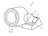
- FIG. 1 is a perspective view showing a specific example of the appearance of a blood pressure measurement device (hereinafter referred to as a sphygmomanometer) 1 which is an embodiment of the blood pressure measurement device of the present invention.
- a sphygmomanometer a blood pressure measurement device
- a sphygmomanometer 1 mainly includes a main body 2 placed on a desk or the like, and a measurement unit 5 for inserting an upper arm as a measurement site.
- a measurement unit 5 for inserting an upper arm as a measurement site.
- the measuring unit 5 is attached to the main body 2 at a variable angle, and includes a housing 6 that is a substantially cylindrical machine frame, and an air bag (an air bag to be described later) housed in the inner periphery of the housing 6. 13).
- the air bag 13 accommodated in the inner peripheral portion of the housing 6 is not exposed and is covered with the cover 7 in a normal use state.
- the cover 7 and the air bag 13 constitute a cuff.
- the blood pressure of the measurer is measured by adjusting the internal pressure (cuff pressure) of the cuff.
- FIG. 2 is a schematic cross-sectional view of the sphygmomanometer 1 during blood pressure measurement.
- the measurer when measuring blood pressure, the measurer inserts the upper arm A into the housing 6 and places the elbow on the elbow rest to instruct the start of measurement. Air is appropriately fed into the air bag 13 included in the cover 7 (not shown in FIG. 2). Thereby, the upper arm A is compressed by the air bag 13.
- the cover 7 is made of, for example, cloth, and is configured to press the arm of the measurer together with the air bag 13 when the air bag 13 is inflated with air.
- FIG. 3 is a block diagram illustrating a specific example of a functional configuration of the sphygmomanometer 1.
- the sphygmomanometer 1 includes the air bag 13 as described above, and is connected to the measurement air system 20.
- the measurement air system 20 includes a pressure sensor 23 that measures the internal pressure of the air bladder 13, a pump 21 that supplies air to the air bladder 13, and a valve 22 that exhausts air.
- the pump 21 constitutes a pressurizing unit that pressurizes the cuff. As long as the cuff can be pressurized, the pressurizing unit may be configured by a device other than the pump.
- the pressure sensor 23 constitutes a detection unit that detects the cuff pressure.
- the sphygmomanometer 1 is connected to a CPU 40 that controls the overall operation of the sphygmomanometer 1, an amplifier 28 connected to the measurement air system 20, a pump drive circuit 26, a valve drive circuit 27, and an amplifier 28.
- a / D (Analog to Digital) converter 29 a memory unit 41 for storing a program executed by the CPU 40 and a measurement result, a display unit 4 for displaying the measurement result, an operation unit including a measurement start button and a power button 3.
- a speaker 51 for outputting sound and a microphone 52 installed in the cover 7 for detecting a Korotkoff sound of the measurer are included.
- the CPU 40 executes a predetermined program stored in the memory unit 41 based on the operation signal input from the operation unit 3, and outputs a control signal to the pump drive circuit 26, and the valve drive circuit 27. Includes a valve control unit 40B for outputting a control signal.
- the pump drive circuit 26 and the valve drive circuit 27 drive the pump 21 and the valve 22 according to the control signal, and execute a blood pressure measurement operation.
- the CPU 40 performs the process described in this specification by executing a program recorded in the memory unit 41 or by executing a program recorded in a recording medium that is removable from the main body of the sphygmomanometer 1.
- Execute. Storage media include CD-ROM (Compact Disc-Read Only Memory), DVD-ROM (Digital Versatile Disk-Read Only Memory), USB (Universal Serial Bus) memory, memory card, FD (Flexible Disk), hard disk, magnetic Tape, cassette tape, MO (Magnetic Optical Disc), MD (Mini Disc), IC (Integrated Circuit) card (excluding memory card), optical card, mask ROM, EPROM, EEPROM (Electronically Erasable Programmable Read-Only Memory), etc. And a medium for storing the program in a nonvolatile manner.
- the pressure sensor 23 detects the internal pressure of the air bladder 13 and inputs the detected pressure signal to the amplifier 28.
- the input pressure signal is amplified to a predetermined amplitude by the amplifier 28, converted into a digital signal by the A / D converter 29, and then input to the CPU 40.
- the CPU 40 determines the blood pressure value of the measurer based on (the amplitude of) the pulse wave of the measurer detected by the pressure sensor 23. Specifically, the CPU 40 appropriately controls the valve drive circuit 27 after raising the internal pressure of the air bladder 13 to a predetermined pressure (pressure PM which is a pressurization target described later) higher than the maximum blood pressure of the measurer. By doing so, the internal pressure is decreased (decreased) at a constant speed.
- the CPU 40 includes a cuff pressure determination unit 40C that determines a pressurization target value of the cuff pressure according to a blood pressure measurement process described later.
- the CPU 40 includes an amplitude value calculation unit 40D that calculates an amplitude value of each pulse wave from a change in the volume of the artery caused by being compressed by the cuff in a part of the body of the measurer.
- the CPU 40 constitutes a calculation unit.
- the CPU 40 includes a blood pressure determination unit 40E that determines a blood pressure value (maximum blood pressure value, minimum blood pressure value) based on the degree of change of the pulse wave amplitude value in the step of reducing the internal pressure of the air bladder 13. As will be described later, the blood pressure determination unit 40E obtains an envelope of the pulse wave amplitude, and determines a predicted minimum blood pressure and a predicted maximum blood pressure, which will be described later, based on the envelope.
- a blood pressure value maximum blood pressure value, minimum blood pressure value
- the cuff pressure is increased as a preparation step for determining the maximum blood pressure and the minimum blood pressure as described above.
- the amplitude of the pulse wave is detected and based on the detected amplitude.
- the predicted values of the minimum blood pressure and the maximum blood pressure (hereinafter referred to as “predicted minimum blood pressure” and “predicted maximum blood pressure”) are determined. A method for determining these predicted values will be described with reference to FIG.
- the final systolic blood pressure and the diastolic blood pressure are measured, and the final systolic blood pressure thus determined is determined.
- each blood pressure determined in the preparation process is referred to as “prediction”.
- the present invention is not limited to the type of sphygmomanometer that determines the final systolic blood pressure and diastolic blood pressure in the depressurization step after pressurization, as in the sphygmomanometer 1 of the present embodiment. It can also be applied to a sphygmomanometer of the type that determines the final systolic and diastolic blood pressure (not provisional) in the pressure process.
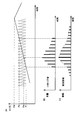
- FIG. 4 shows graphs (A) to (C) in order to explain changes in the volume and pulse wave amplitude of the Korotkoff sound with respect to changes in cuff pressure during blood pressure measurement by the sphygmomanometer 1.
- FIG. 4A a change in cuff pressure is shown by a solid line.
- the cuff pressure is increased at a constant speed (so that the increasing pressure per unit time is constant) to the pressure PM, which is the pressurization target value, and then at a constant speed.
- the state controlled to decrease is shown.
- the vertical axis indicates the volume of the Korotkoff sound, and the horizontal axis indicates the passage of time.
- the step of increasing the cuff pressure to the pressure PM corresponds to the above-described preparation step.
- FIG. 4A for reference, the waveform of a normal pulse wave when it is assumed that no pressure is applied is shown by a dotted line.
- FIG. 4B shows a change in the volume of the Korotkoff sound detected via the microphone 52 corresponding to the change in the cuff pressure shown in FIG. If the cuff pressure gradually increases, the Korotkoff sound begins to be detected when the cuff pressure reaches the pressure P1 corresponding to the measurer's lowest blood pressure, and its volume gradually increases and shows a maximum value. When the cuff pressure exceeds a value P2 corresponding to the maximum blood pressure of the measurer, the cuff pressure is not detected.
- FIG. 4C shows information on the pulse wave amplitude.
- FIG. 4C shows a change in the pulse wave amplitude corresponding to the change in the cuff pressure shown in FIG.
- the pulse wave amplitude gradually increases as the cuff pressure increases, and when the cuff pressure reaches the minimum blood pressure P1, the rate of increase (the amplitude per unit time increases). Ratio) greatly changes (becomes higher).
- the pulse wave amplitude increases with increasing cuff pressure, decreases after reaching a maximum value, and when the cuff pressure exceeds the maximum blood pressure P2, the rate of decrease decreases, and the pulse wave amplitude gradually decreases thereafter.
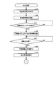
- FIG. 5 and 6 are flowcharts of blood pressure measurement processing executed by the CPU 40.
- step S10 the CPU 40 starts pressurization of the blood pressure measurement cuff (air bag 13) and advances the process to step S20.
- step S20 the CPU 40 starts calculating the pulse wave amplitude by measuring the pulse wave based on the pulse pressure signal superimposed on the signal detected by the pressure sensor 23, and advances the process to step S30.
- the CPU 40 stores the calculated pulse wave amplitude in the memory unit 41 in association with the cuff pressure corresponding to the pulse wave amplitude.
- step S30 the CPU 40 plots the pulse wave amplitude calculated in step S20 to obtain an envelope, determines whether or not a rising point can be extracted from the envelope, and determines that extraction is possible, step S40. Proceed to the process. For example, as shown in FIG. 4C, the CPU 40 plots the pulse wave amplitude calculated in step S ⁇ b> 20 to obtain an envelope, calculates a secondary difference value for the envelope, and calculates the secondary When the difference value exceeds a predetermined reference value, it is determined that the rising point can be extracted.
- step S40 the pulse wave amplitude corresponding to the rising point determined to be extracted in step S30 is stored in the memory unit 41, and the process proceeds to step S50.
- step S50 the CPU 40 determines whether or not an inflection point has appeared for the pulse wave amplitude calculated continuously.
- the determination in step S50 is realized, for example, according to the determination of the presence or absence of an existing inflection point for the envelope as shown by the broken line in FIG. If CPU 40 determines that an inflection point has appeared, the process proceeds to step S60.
- step S60 the CPU 40 calculates a predicted systolic blood pressure value based on the cuff pressure at the inflection point acquired in step S50, and advances the process to step S70.
- the details of calculating the predicted systolic blood pressure value will be described later.
- step S70 the CPU 40 calculates the pressurization target value PM by adding a predetermined margin value to the predicted systolic blood pressure value calculated in step S60, and advances the process to step S80.
- step S80 CPU 40 uses pressurization target value PM calculated in step S70, the current cuff pressure, and the pressurization speed (of the cuff continued from step S10).
- the remaining time until the cuff pressure is increased to the pressurization target value (remaining pressurization time) is calculated, and the process proceeds to step S90.
- the difference between the pressurization target value and the current cuff pressure is calculated, and a value obtained by dividing the difference by the pressurization speed is set as the remaining pressurization time.
- step S90 the CPU 40 notifies the remaining pressurization time calculated in step S80 and advances the process to step S100.
- step S100 the CPU 40 determines whether or not the current cuff pressure P has reached the pressurization target value PM. If it is determined that the cuff pressure P has not yet reached, the process returns to step S80. The pressure is stopped, and the process proceeds to step S110. Up to this point corresponds to the above-described preparation process.
- step S110 the CPU 40 appropriately controls the valve drive circuit 27 to perform a process of reducing the pressure of the blood pressure measurement cuff (air bag 13) at a constant speed, and advances the process to step S120.
- the process in step S110 is continued until at least a process in step S130 described later is executed.
- step S120 the CPU 40 determines the maximum blood pressure value of the measurer and advances the process to step S130.
- step S130 the CPU 40 determines the minimum blood pressure value of the measurer. When the determination of the minimum blood pressure value is completed, the CPU 40 ends the blood pressure measurement process. It should be noted that a known technique can be employed for determination of the systolic blood pressure value in step S120 and determination of the diastolic blood pressure value in step S130, and therefore detailed description thereof will not be repeated here.
- the cuff pressure at the inflection point acquired in step S50 is used to calculate the predicted systolic blood pressure value.
- the cuff pressure at the inflection point is referred to as P INF .
- the predicted maximum blood pressure is based on the data obtained until the maximum value in the envelope is detected. A value is calculated.
- P MAX indicates a blood pressure value when the envelope EC is predicted to take a maximum value.
- ⁇ A 1 indicates a difference in pulse wave amplitude from the inflection point of the envelope to a point predicted to be the maximum point
- ⁇ A 2 is the maximum from the point predicted to be the maximum point.
- the difference in pulse wave amplitude up to the point where hypertension is predicted is shown.
- ⁇ P 1 indicates the difference in cuff pressure from the inflection point to the point predicted to be the maximum point
- ⁇ P 2 indicates the difference in predicted maximum blood pressure value from the point at which the blood pressure value at the maximum point is predicted.
- Equation (1) P MAX , ⁇ P 1 , ⁇ A 1, and ⁇ A 2 as shown in Equation (1).
- FIG. 8 shows the measured value (RP MAX ) of the blood pressure value at the maximum point of the pulse wave amplitude with respect to the measured value (RP INF ) of the cuff pressure at the inflection point of the pulse wave amplitude for each measurement in a plurality of blood pressure measurements.
- multiple blood pressure measurements mean multiple blood pressure measurements for the same person or multiple persons.
- the actual measurement value is obtained based on the envelope indicating the change in the pulse wave amplitude accompanying the change in the cuff pressure, which is used to determine the final blood pressure value (not the provisional measurement in the preparation process).
- the cuff pressure is controlled so as to decrease at a constant speed from the pressure PM, which is the pressurization target value.
- Equation (2) ⁇ 1 and ⁇ 1 are experimentally obtained constants. It is assumed that ⁇ 1 and ⁇ 1 are recorded in advance in the memory unit 41 (or a recording medium that can be attached to and detached from the main body of the sphygmomanometer 1).
- the CPU 40 can acquire P INF in step S50.
- Equation (2) P INF is substituted into equation (2) as RP INF.
- RP MAX can be acquired. Then, by regarding the RP MAX and P MAX, you can acquire the P MAX. That is, P MAX can be acquired (calculated) using ⁇ 1 and ⁇ 1 and data (P INF ) obtained until the maximum value of the pulse wave amplitude is detected in the preparation step.
- the CPU 40 can calculate ⁇ P 1 using P INF based on the equations (2) and (3).
- ⁇ A 1 has a linear relationship with the difference between A INF and A MIN .
- a INF is the pulse wave amplitude corresponding to the inflection point of the envelope acquired in step S50.
- a MIN is the pulse wave amplitude corresponding to the rise of the envelope acquired in step S30.
- ⁇ A 2 has a linear relationship with A MAX .
- a MAX is a pulse wave amplitude corresponding to the maximum point.
- the CPU 40 can acquire the rising point of the envelope in step S40 described above, the CPU 40 can acquire A MIN as the corresponding pulse wave amplitude.
- CPU40 acquires the cuff pressure of the inflection point of envelope EC in above-described step S50. Therefore, the CPU 40 can acquire A INF as the pulse wave amplitude corresponding to this.
- the CPU 40 can acquire ⁇ A 1 . Further, the inventor of the present application has found that the pulse wave amplitude at the inflection point and the maximum point has a primary relationship in the envelope of the pulse wave amplitude during the period of increasing the cuff pressure in blood pressure measurement. This will be described with reference to FIG.
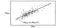
- FIG. 9 is a plot diagram of the measured value (RA MAX ) of the pulse wave amplitude at the maximum point with respect to the measured value (RA INF ) of the pulse wave amplitude at the inflection point of the envelope for each measurement in a plurality of blood pressure measurements.
- the plurality of blood pressure measurements mean a plurality of blood pressure measurements for the same person or a plurality of persons, as described with reference to FIG.
- RA INF and RA MAX are considered to have a primary relationship.
- these relationships are expressed by the following formula (6).
- ⁇ 4 and ⁇ 4 are constants obtained experimentally, and are recorded in advance in the memory unit 41 (or a recording medium detachable from the main body of the sphygmomanometer 1). To do.
- equation (6) be estimated and 'in alpha 4' and beta 4 'approximates the alpha 4 and beta 4 in the formula (6), CPU 40 has the formula using the alpha 4 and beta 4 (6)
- RA MAX can be calculated by using A INF instead of RA INF .
- the calculated RA MAX by regarded as A MAX can obtain A MAX. That is, A MAX can be obtained (calculated) using A INF , ⁇ 4, and ⁇ 4 according to Equation (6).
- the CPU 40 can obtain ⁇ A 2 according to the equation (5) using A MAX , ⁇ 3, and ⁇ 3 calculated in this way.
- the CPU 40 can calculate P SBP according to equation (1) using P MAX , ⁇ P 1 , ⁇ A 1, and ⁇ A 2 calculated as described above.
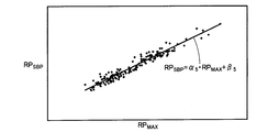
- FIG. 10 is a plot of the measured value (RP SBP ) of the maximum blood pressure value with respect to the measured value (RP MAX ) of the blood pressure value at the maximum point of the envelope for each measurement in a plurality of blood pressure measurements.
- the plurality of blood pressure measurements mean a plurality of blood pressure measurements for the same person or a plurality of persons, as described with reference to FIG.
- RP MAX and RP SBP are considered to have a primary relationship.
- these relationships are expressed by the following equation (7).
- ⁇ 5 and ⁇ 5 are constants obtained experimentally, and are recorded in advance in the memory unit 41 (or a recording medium that can be attached to and detached from the main body of the sphygmomanometer 1). To do.
- equation (7) 'in the alpha 5' and beta 5 'approximates a beta 5 and alpha 5 in the formula (7) CPU 40 may, as long to obtain a P MAX, the P MAX Equation (7) the RP SBP derived by substituting can acquire the P SBP by regarding the P SBP to. Then, as described above, P MAX is based on the estimation that ⁇ 1 ′ and ⁇ 1 ′ in equation (2) ′ approximate ⁇ 1 and ⁇ 1 in equation (2). the P INF calculates the RP MAX used as RP INF, the RP MAX can be obtained by regarding a the P MAX in accordance.
- the CPU 40 can calculate P SBP according to the equations (2) and (7). That is, according to the second calculation mode, P SBP can be calculated using only a single measurement value P INF obtained in the preparation step based on the above estimation.
- the maximum of the envelope is obtained based on the cuff pressure (P INF ) corresponding to the amplitude value until the envelope of the pulse wave amplitude shows the maximum value by following the equation (2).
- the blood pressure value corresponding to the value is predicted.
- Formula (7) based on the information showing the primary relationship between the blood pressure value (P MAX ) and the maximum blood pressure value (P SBP ) corresponding to the maximum value of the envelope, the person to be measured Determine the systolic blood pressure value.
- the notification mode may be voice or display.
- notification may be performed by vibration.
- a message such as “Pressure will be finished in 2 seconds” may be output from the speaker 51, or music is output from the speaker 51 while increasing the cuff pressure. It is also conceivable to reduce the volume of the music being output according to the decrease in the remaining pressure time. In this way, by notifying the remaining pressurization time, the measurer can recognize the remaining time of the process of “pressurization” in which the strength of compression by the air bag 13 on his / her arm is increased.
- the pressurization target value calculated in step S70 may be notified as it is.
- a message such as “Pressure is applied to XXX mmHg” is output from the speaker 51.
- Such voice notification may be continuously performed until the cuff pressure P reaches the pressurization target value PM, or may be performed only once after the pressurization target value is calculated in step S70.
- the notification may be made in response to the operation of the operation unit 3 before the cuff pressure P reaches the pressurization target value PM after being performed only once.
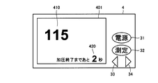
- FIG. 11A and FIG. 11B are diagrams showing examples of display modes of the display device 4 when the notification is performed by display.
- the display device 4 is provided with a display device 401 formed of an LCD (Liquid Crystal Display) or the like. Further, the display 4 is provided with a power key 31, a measurement key 32, a left key 33, and a right key 34 that constitute the operation unit 3.
- the power key 31 is operated in order to switch power on / off in the sphygmomanometer 1
- the measurement key 32 is operated in order to instruct the start of blood pressure measurement processing
- the left key 33 and right key. 34 is operated when selecting the content displayed on the display device 401.
- the display column 410 displays the current cuff pressure
- the display column 420 displays a message for informing the remaining pressurization time.
- FIG. 11B shows a display mode of the display 4 different from FIG. 11A.
- a first display unit 431 including nine indicators arranged in the vertical direction and a plurality of indicators included in the first display unit 431 are included.
- a second display unit 432 that is displayed to indicate an indicator corresponding to the end of pressurization is displayed.
- the remaining pressure time is notified by changing the display color in order from the bottom according to the length of the remaining pressure time for the eight indicators except the one indicator at the top.
- the second display unit 432 is always an indicator located in the upper part of the indicators included in the first display unit 431 except those that are not substantially used for notification of the remaining pressure time (FIG. 11B). In the example shown in (2), the second indicator) is displayed.
- the first display unit 431 excludes the indicator (one indicator located at the top in the example shown in FIG.
- the display pressure of the eight indicators is changed in order from the bottom to notify the remaining pressure time.
- the remaining pressurization time calculated in step S90 is divided into eight equal parts, and the above-mentioned every time the eight equal time has elapsed.
- the display colors of the eight indicators are changed one by one from the bottom.
- the display colors of the four indicators from the bottom among the eight indicators that are substantially used for notification among the nine indicators of the first display unit 431 are changed from the initial display colors. The state is shown.
- the remaining pressurization time can be notified by display.
- the remaining pressure time may be notified directly as the message 42, or as described with reference to FIG. Notification may be made indirectly, for example, by using the indicator.
- the first display unit 431 some of the uppermost indicators are displayed even though they are not used for reporting the remaining pressurization time. Thereby, even when the cuff pressure reaches the pressurization target value, it is the first display unit 431 that the display color changes in the first display unit 431 is substantially all indicators used for notification. Not all indicators. That is, even when the cuff pressure is increased to the pressurization target value in the sphygmomanometer 1, the display color of some indicators of the first display unit 431 is not changed, so that the measurement person can perform the measurement.
- the blood pressure measurement of the person is performed with a margin for the increase in cuff pressure. In other words, the target pressure value in the blood pressure measurement of the person concerned is the same as or up to that in general blood pressure measurement. It is possible to make the measurer feel that it has not been reached.
- the target cuff pressure is determined based on the pulse wave information. Then, when the pressurization target value is determined, the pressurization target value or information related thereto (such as the remaining time until pressurization to the pressurization target value is completed) is notified.
- the maximum value of the pulse wave amplitude and the cuff pressure corresponding thereto are determined.
- a pressurization target value can also be calculated based on this.
- a relationship is used in which the difference between the blood pressure value corresponding to the maximum value of the minimum blood pressure value and the pulse wave amplitude is twice the difference between the blood pressure value corresponding to the maximum value and the maximum blood pressure value.
- a predicted systolic blood pressure value is calculated. That is, using the predicted minimum blood pressure value and the cuff pressure corresponding to the maximum value, the predicted maximum blood pressure value is calculated according to the relationship.
- the maximum blood pressure value of the measurer is determined based on the amplitude value until the maximum value is shown in the envelope of the pulse wave amplitude.
- the measurer can recognize his / her systolic blood pressure earlier than before. Thereby, the stress of the measurer at the time of blood pressure measurement using a blood pressure measuring device can be relieved.
Landscapes
- Health & Medical Sciences (AREA)
- Life Sciences & Earth Sciences (AREA)
- Vascular Medicine (AREA)
- Cardiology (AREA)
- Biomedical Technology (AREA)
- Heart & Thoracic Surgery (AREA)
- Physiology (AREA)
- Biophysics (AREA)
- Pathology (AREA)
- Engineering & Computer Science (AREA)
- Ophthalmology & Optometry (AREA)
- Physics & Mathematics (AREA)
- Medical Informatics (AREA)
- Molecular Biology (AREA)
- Surgery (AREA)
- Animal Behavior & Ethology (AREA)
- General Health & Medical Sciences (AREA)
- Public Health (AREA)
- Veterinary Medicine (AREA)
- Measuring Pulse, Heart Rate, Blood Pressure Or Blood Flow (AREA)
Abstract
血圧測定装置(1)では、カフ圧に基づいて被測定者の最高血圧値を決定される。また、カフ(7,13)が加圧される期間において算出された脈波の振幅値が、対応する前記カフ圧に従って配列されたときの、包絡線を求められる。そして、当該包絡線が極大値を示すまでの振幅値と当該振幅値に対応する前記カフ圧とに基づいて、または、当該振幅値に対応するカフ圧に基づいて、被測定者の最高血圧値が決定される。
Description
本発明は、血圧測定装置に関し、特に、血圧測定時の測定者のストレスを緩和できる血圧測定装置、および、そのような血圧測定装置を制御するためのプログラムを記憶した記憶媒体に関する。
従来から、電子血圧計において、まずカフ圧を所定の圧まで上昇させ、そして、カフ圧を徐々に下げながら、脈波振幅の変化を継続的に検出することにより、測定者の最高血圧と最低血圧が順に決定されて、平均血圧が算出されていた。
このような電子血圧計において、カフ圧の上昇により測定者がカフの装着部位において感じる圧迫感が上昇していくことや、測定ごとにカフ圧の上昇目標である上記「所定の圧」が異なるような場合には、カフ圧の上昇がいつまで続くのかなどの理由から、測定者はストレスを感じる場合があった。
このような電子血圧計に関し、従来から種々の技術が開示されている。たとえば、文献1(特開平04-261639号公報)には、カフ圧の上昇目標を測定者の血圧に応じたものとする技術が開示されている。かかる技術では、カフ圧を上昇させている期間中に脈波振幅が算出され、当該脈波振幅の最大値が検出されると、当該最大値に基づいてしきい値が算出され、そして、カフ圧が当該しきい値に達した時点でカフの加圧が停止されて、カフ圧が下げられる。
また、文献2(特開2009-233011号公報)には、カフ圧を上昇させている期間中の脈波振幅の極大値を検出し、当該極大値に対応するカフ圧から加圧目標値を算出して、報知する技術が開示されている。
血圧測定装置において、血圧測定時の測定者のストレスの緩和は、常に切望されることである。
本発明は、係る実情に鑑み考え出されたものであり、血圧測定装置における、血圧測定時の測定者のストレスのさらなる緩和を目的とするものである。
本発明に従った血圧測定装置は、カフと、カフを加圧する加圧部と、カフの内部の圧力であるカフ圧を検出する検出部と、カフに圧迫されて生じる動脈の容積変化から各脈波の振幅値を算出する算出部と、算出部が算出する振幅値と、算出部が算出する振幅値に対応したカフ圧とを、関連付けて記憶する記憶部とを備える。また、算出部は、カフ圧に基づいて被測定者の最高血圧値を決定し、加圧部がカフを加圧する期間において算出された脈波の振幅値が、対応するカフ圧に従って配列されたときの、包絡線を求め、当該包絡線が極大値を示すまでの振幅値と当該振幅値に対応するカフ圧とに基づいて、または、当該振幅値に対応するカフ圧に基づいて、被測定者の最高血圧値を決定する。
本発明に従った記憶媒体は、血圧測定装置のカフの圧力を調整することにより血圧測定を行なうための血圧測定用プログラムを記憶する記憶媒体である。血圧測定用プログラムは、血圧測定装置が備えるコンピュータに、カフを加圧するステップと、カフの内部の圧力であるカフ圧を検出するステップと、カフに圧迫されて生じる動脈の容積変化から各脈波の振幅値を算出するステップと、算出した振幅値と、算出した振幅値に対応したカフ圧とを、関連付けて記憶するステップと、カフ圧に基づいて被測定者の最高血圧値を決定するステップとを実行させる。決定するステップは、カフを加圧する期間における算出された脈波の振幅値が、対応するカフ圧に従って配列されたときの、包絡線を求めるステップと、当該包絡線が極大値を示すまでの振幅値と、当該極大値を示すまでの振幅値に対応するカフ圧とに基づいて、被測定者の最高血圧値を決定するステップとを実行させる。
本発明によれば、測定者は従来よりも早期に自己の最高血圧値を認識でき、よって、血圧測定時の測定者のストレスを緩和できる。
以下に、図面を参照しつつ、本発明の血圧測定装置の実施の形態について説明する。以下の説明では、同一の部品および構成要素には同一の符号を付してある。それらの名称および機能も同じである。
[1.血圧測定装置の全体構成]
図1は、本発明の血圧測定装置の一実施の形態である血圧測定装置(以下、血圧計)1の外観の具体例を示す斜視図である。
図1は、本発明の血圧測定装置の一実施の形態である血圧測定装置(以下、血圧計)1の外観の具体例を示す斜視図である。
図1を参照して、本実施の形態にかかる血圧計1は、主に、机等に載置される本体2と、測定部位である上腕を差込むための測定部5とを備える。本体2の上部には、電源ボタンや測定ボタンなどが配置された操作部3と、表示器4と、肘置きとが備えられる。また、測定部5は、本体2に対して角度が可変に取付けられており、略円筒状の機枠であるハウジング6と、ハウジング6の内周部に収納された空気袋(後述する空気袋13)とを備える。なお、図1に示されるように、通常の使用状態においてハウジング6の内周部に収納された空気袋13は露出しておらず、カバー7によって覆われている。
本実施の形態では、カバー7および空気袋13により、カフが構成される。そして、血圧計1では、カフの内圧(カフ圧)が調整されることにより、測定者の血圧が測定される。
図2は、血圧測定時の血圧計1の断面概略図である。図2を参照して、血圧測定の際には、測定者は、ハウジング6の内部に上腕Aを差込んで上記肘置きに肘を載置して、測定開始を指示する。カバー7(図2では、図示略)に内包される空気袋13に適宜空気が送り込まれる。これにより、上腕Aは、当該空気袋13によって圧迫される。カバー7は、たとえば布製であり、空気袋13が空気を送り込まれて膨張することにより、空気袋13とともに測定者の腕を圧迫するように構成されている。
図3は、血圧計1の機能構成の具体例を示すブロック図である。
図3を参照して、血圧計1は上記のように空気袋13を含み、測定用エア系統20に接続されている。測定用エア系統20には、空気袋13の内圧を測定する圧力センサ23、空気袋13に対する給気を行なうポンプ21、および排気を行なう弁22が含まれる。本実施の形態では、ポンプ21により、カフを加圧する加圧部が構成されている。なお、カフを加圧することができれば、加圧部は、ポンプ以外の装置から構成されても良い。また、圧力センサ23により、カフ圧を検出する検出部が構成されている。
図3を参照して、血圧計1は上記のように空気袋13を含み、測定用エア系統20に接続されている。測定用エア系統20には、空気袋13の内圧を測定する圧力センサ23、空気袋13に対する給気を行なうポンプ21、および排気を行なう弁22が含まれる。本実施の形態では、ポンプ21により、カフを加圧する加圧部が構成されている。なお、カフを加圧することができれば、加圧部は、ポンプ以外の装置から構成されても良い。また、圧力センサ23により、カフ圧を検出する検出部が構成されている。
また、血圧計1には、当該血圧計1の動作を全体的に制御するCPU40、測定用エア系統20に接続される増幅器28、ポンプ駆動回路26、ならびに弁駆動回路27、増幅器28に接続されるA/D(Analog to Digital)変換器29、CPU40で実行されるプログラムや測定結果を記憶するメモリ部41、測定結果等を表示する表示器4、測定開始ボタンや電源ボタンなどを含む操作部3、音声を出力するスピーカ51、および、カバー7内に設置され測定者のコロトコフ音を検出するためのマイク52が含まれる。
CPU40は、操作部3から入力される操作信号に基づいてメモリ部41に記憶されている所定のプログラムを実行し、ポンプ駆動回路26に制御信号を出力するポンプ制御部40Aと、弁駆動回路27に制御信号を出力する弁制御部40Bを含む。ポンプ駆動回路26および弁駆動回路27は、当該制御信号に従ってポンプ21および弁22を駆動させ、血圧測定動作を実行させる。
CPU40は、メモリ部41に記録されたプログラムを実行することにより、または、血圧計1本体に対して着脱可能な記録媒体に記録されたプログラムを実行することにより、本明細書に記載の処理を実行する。記憶媒体としては、CD-ROM(Compact Disc - Read Only Memory)、DVD-ROM(Digital Versatile Disk - Read Only Memory)、USB(Universal Serial Bus)メモリ、メモリカード、FD(Flexible Disk)、ハードディスク、磁気テープ、カセットテープ、MO(Magnetic Optical Disc)、MD(Mini Disc)、IC(Integrated Circuit)カード(メモリカードを除く)、光カード、マスクROM、EPROM、EEPROM(Electronically Erasable Programmable Read-Only Memory)などの、不揮発的にプログラムを格納する媒体が挙げられる。
圧力センサ23は空気袋13の内圧を検出し、検出した圧力信号を増幅器28に入力する。入力された圧力信号は、増幅器28において所定の振幅まで増幅され、A/D変換器29においてデジタル信号に変換された後に、CPU40に入力される。
CPU40には、圧力センサ23において検出される測定者の脈波(の振幅)に基づいて、測定者の血圧値を決定する。具体的には、CPU40は、空気袋13の内圧を測定者の最高血圧よりも高い所定の圧力(後述する、加圧目標である圧PM)まで上昇させた後、弁駆動回路27を適宜制御することにより、当該内圧を一定の速度で減少(下降)させていく。CPU40には、後述する血圧測定処理に従ってカフ圧の加圧目標値を決定するカフ圧決定部40Cが含まれる。
また、CPU40には、測定者の体の一部において、カフに圧迫されて生じる動脈の容積変化から各脈波の振幅値を算出する振幅値算出部40Dが含まれる。本実施の形態では、CPU40により、算出部が構成される。
さらに、CPU40には、空気袋13の内圧を低下させる工程において、脈波振幅値の変化の度合いに基づき血圧値(最高血圧値、最低血圧値)を決定する、血圧決定部40Eが含まれる。なお、血圧決定部40Eは、後述するように、脈波振幅の包絡線を求め、当該包絡線に基づいて、後述する予測最低血圧および予測最高血圧を決定する。
また、血圧計1では、上記のように最高血圧および最低血圧の決定の準備工程としてカフ圧を上昇させているが、この準備工程においても脈波の振幅を検出し、検出した振幅に基づいて最低血圧と最高血圧の予測値(以下、「予測最低血圧」「予測最高血圧」と呼ぶ)を決定する。これらの予測値の決定方法について、図4を参照して説明する。
なお、本実施の形態では上記準備工程の後に実行される、カフ圧を下降させていく工程において、最終的な最高血圧および最低血圧の測定がなされ、このように決定される最終的な最高血圧および最低血圧と、準備工程において暫定的に決定される最高血圧および最低血圧とを区別するために、ここでは準備工程において決定される各血圧に「予測」と付すこととする。
ただし、本発明は、本実施の形態の血圧計1のように、加圧後の減圧工程において最終的な最高血圧および最低血圧を決定するタイプの血圧計に限定されず、最初に実行する加圧工程において(暫定的ではなく)最終的な最高血圧および最低血圧を決定するタイプの血圧計にも適用できる。
図4には、血圧計1の血圧測定時のカフ圧変化に対するコロトコフ音の音量および脈波振幅の変化を説明するために(A)~(C)のグラフが示されている。まず、図4の(A)では、実線で、カフ圧の変化が示されている。
図4の(A)では、カフ圧が、加圧目標値である圧PMまで、一定の速度で(単位時間あたりの上昇する圧が一定となるように)上昇させた後、一定の速度で減少するように制御される状態が示されている。縦軸はコロトコフ音の音量を示し、横軸は時間の経過を示す。カフ圧を圧PMまで上昇させる工程は、上記した準備工程に対応している。
なお、図4の(A)では、参考として、点線で、加圧されていないと仮定したときの通常の脈波の波形が示されている。
図4の(B)は、(A)に示されたカフ圧の変化に対応した、マイク52を介して検出されるコロトコフ音の音量の変化を示している。カフ圧が徐々に上昇した場合、コロトコフ音は、カフ圧が測定者の最低血圧に対応する圧P1となったときに検出され始め、その音量は徐々に大きくなり、極大値を示した後、カフ圧が測定者の最高血圧に対応する値P2を超えると検出されなくなる。
図4の(C)は、脈波振幅に関する情報を示している。具体的には、図4の(C)には、(A)に示されたカフ圧の変化に対応した、脈波振幅の変化が示されている。脈波振幅は、カフ圧が測定者の最低血圧P1よりも低い領域では、カフ圧の上昇とともに徐々に上昇し、カフ圧が最低血圧P1となると、その上昇率(単位時間当たりの振幅が増加する割合)が大きく変化する(高くなる)。その後、カフ圧の上昇とともに脈波振幅は上昇し、極大値を示した後減少し、カフ圧が最高血圧P2を越えると、減少率が低くなり、その後も脈波振幅は徐々に減少していく。
[2.血圧測定処理]
次に、血圧計1において測定者の最高血圧値と最低血圧値が測定される際に、CPU40が実行する処理(血圧測定処理)の内容について説明する。図5および図6は、CPU40が実行する血圧測定処理のフローチャートである。
次に、血圧計1において測定者の最高血圧値と最低血圧値が測定される際に、CPU40が実行する処理(血圧測定処理)の内容について説明する。図5および図6は、CPU40が実行する血圧測定処理のフローチャートである。
まず図5を参照して、血圧測定処理では、CPU40は、まずステップS10で、血圧測定用のカフ(空気袋13)の加圧を開始して、ステップS20へ処理を進める。
ステップS20では、CPU40は、圧力センサ23により検出される信号に重畳する脈圧信号に基づいて脈波を計測することによる脈波振幅の算出を開始して、ステップS30へ処理を進める。なお、CPU40は、算出した脈波振幅を、当該脈波振幅に対応するカフ圧と関連付けて、メモリ部41に記憶させる。
ステップS30では、CPU40は、ステップS20において算出した脈波振幅をプロットして包絡線を求め、そして、当該包絡線において立ち上がり点が抽出できるか否かを判断し、抽出できると判断すると、ステップS40へ処理を進める。CPU40は、たとえば、図4の(C)に示したように、ステップS20において算出した脈波振幅をプロットして包絡線を求め、当該包絡線について、2次差分値を算出し、当該2次差分値が予め定められた基準値を超えた場合に、立ち上がり点が抽出できると判断する。
ステップS40では、ステップS30で抽出できると判断した立ち上がり点について、当該立ち上がり点に対応する脈波振幅をメモリ部41に記憶させて、ステップS50へ処理を進める。
ステップS50では、CPU40は、さらに継続して算出している脈波振幅について、変曲点が出現したか否かを判断する。ステップS50の判断は、たとえば、図4の(C)に破線で示したような包絡線についての既存の変曲点の有無の判断に従って、実現される。そして、CPU40は、変曲点が出現したと判断するとステップS60へ処理を進める。
ステップS60では、CPU40は、ステップS50で取得した変曲点のカフ圧等に基づいて予測最高血圧値を算出して、ステップS70へ処理を進める。なお、予測最高血圧値の算出の内容は、後述する。
ステップS70では、CPU40は、ステップS60で算出した予測最高血圧値に、予め定められた余裕値を加算することにより、加圧目標値PMを算出して、ステップS80へ処理を進める。
図6を参照して、ステップS80では、CPU40は、ステップS70で算出した加圧目標値PMと、現在のカフ圧と、(ステップS10から継続しているカフの)加圧速度とを用いて、加圧目標値までカフ圧を上昇させるまでの残り時間(加圧残り時間)を算出して、ステップS90へ処理を進める。なお、ここでは、具体的には、加圧目標値と現時点のカフ圧との差が算出され、そして、当該差を加圧速度で除して得られる値が加圧残り時間とされる。
ステップS90では、CPU40は、ステップS80で算出した加圧残り時間を報知して、ステップS100へ処理を進める。
ステップS100では、CPU40は、現時点のカフ圧Pが加圧目標値PMに達したか否かを判断し、まだ達していないと判断するとステップS80へ処理を戻し、達したと判断するとカフの加圧を停止し、ステップS110へ処理を進める。ここまでが、上記した準備工程に相当する。
ステップS110では、CPU40は、弁駆動回路27を適宜制御することにより、血圧測定用カフ(空気袋13)を一定の速度で減圧する処理を行ない、ステップS120へ処理を進める。なお、ステップS110における処理は、少なくとも、後述するステップS130の処理が実行されるまで継続される。
ステップS120では、CPU40は、測定者の最高血圧値を決定し、ステップS130へ処理を進める。
ステップS130では、CPU40は、測定者の最低血圧値を決定する。
そして、最低血圧値の決定が終了すると、CPU40は、血圧測定処理を終了させる。なお、ステップS120における最高血圧値の決定、および、ステップS130における最低血圧値の決定については、周知の技術を採用することができるため、ここでは詳細な説明は繰返さない。
そして、最低血圧値の決定が終了すると、CPU40は、血圧測定処理を終了させる。なお、ステップS120における最高血圧値の決定、および、ステップS130における最低血圧値の決定については、周知の技術を採用することができるため、ここでは詳細な説明は繰返さない。
[3.予測最高血圧値の算出]
次に、ステップS60における予測最高血圧値PSBPの算出の具体例を説明する。
次に、ステップS60における予測最高血圧値PSBPの算出の具体例を説明する。
上記したように、予測最高血圧値の算出には、ステップS50で取得した変曲点のカフ圧が利用される。以下、変曲点のカフ圧をPINFという。
なお、本実施の形態では、脈波振幅の包絡線を作成しつつカフ圧を上昇させた場合に、当該包絡線における極大値が検出されるまでに得られたデータに基づいて、予測最高血圧値が算出される。
[3-1.第1の算出態様]
第1の算出態様では、まず、図7に示した脈波振幅の包絡線ECが、極大値を境に左右対称であると仮定する。なお、図7の包絡線ECは、図4の(C)に示した包絡線に相当する。
第1の算出態様では、まず、図7に示した脈波振幅の包絡線ECが、極大値を境に左右対称であると仮定する。なお、図7の包絡線ECは、図4の(C)に示した包絡線に相当する。
図7において、PMAXは包絡線ECが極大値を取ると予測されるときの血圧値を示す。
また、図7では、△A1は、包絡線の変曲点から極大点と予測される点までの脈波振幅の差を示し、△A2は、当該極大点と予測される点から最高血圧と予測される点までの脈波振幅の差を示す。△P1は、変曲点から極大点と予測される点までのカフ圧の差を示し、△P2は、極大点の血圧値と予測される点から予測最高血圧値の差を示す。
また、図7では、△A1は、包絡線の変曲点から極大点と予測される点までの脈波振幅の差を示し、△A2は、当該極大点と予測される点から最高血圧と予測される点までの脈波振幅の差を示す。△P1は、変曲点から極大点と予測される点までのカフ圧の差を示し、△P2は、極大点の血圧値と予測される点から予測最高血圧値の差を示す。
上記したように、包絡線ECがPMAXを境に左右対称であると仮定しているため、△P2は、△P1に△A1と△A2の比を積算したものとすることができる。つまり、PSBPは、式(1)のように、PMAXと△P1と△A1と△A2によって表わすことができる。

以下、PSBPを算出するために必要なPMAXと△P1と△A1と△A2のそれぞれを算出する方法について説明する。
1)PMAX
まず、本願発明者は、血圧測定においてカフ圧を上昇させる期間中の、脈波振幅の変曲点と極大点に対応する血圧値は一次の関係にあることを発見した。このことを図8を参照して説明する。
まず、本願発明者は、血圧測定においてカフ圧を上昇させる期間中の、脈波振幅の変曲点と極大点に対応する血圧値は一次の関係にあることを発見した。このことを図8を参照して説明する。
図8は、複数回の血圧測定における各測定についての、脈波振幅の変曲点のカフ圧の実測値(RPINF)に対する脈波振幅の極大点の血圧値の実測値(RPMAX)のプロット図である。ここで、複数回の血圧測定とは、同一人または複数人についての複数の血圧測定を意味する。また、実測値とは、(準備工程における暫定的な測定ではなく)最終的な血圧値の決定に利用される、カフ圧の変化に伴う脈波振幅の変化を示す包絡線に基づいて得られた値であることを意味する。本実施の形態では、最終的な血圧値の決定の際には、カフ圧は、上記した加圧目標値である圧PMから一定の速度で減少するように制御される。
そして、図8から理解されるように、RPINFとRPMAXは、一次の関係にあると考えられる。本明細書では、これらの関係を次の式(2)で表わす。なお、式(2)において、α1とβ1は、実験的に得られる定数である。α1およびβ1は、予めメモリ部41(または、血圧計1の本体に対して着脱可能な記録媒体)に記録されているものとする。

一方、図5および図6を参照して説明した血圧測定処理では、CPU40は、ステップS50において、PINFを取得することができる。
したがって、PINFとPMAXの間にRPINFとRPMAXと同様に次の式(2)´の関係があると考えられる。

そして、式(2)´中のα1´とβ1´が式(2)中のα1とβ1に近似すると推定すれば、PINFをRPINFとして式(2)に代入することによりRPMAXを取得できる。そして、RPMAXをPMAXとみなすことにより、PMAXを取得できる。つまり、α1およびβ1と、準備工程において脈波振幅の極大値が検出されるまでに得られるデータ(PINF)とを用いて、PMAXを取得(算出)することができる。
2)△P1
式(1)の△P1は、上記した定義から、式(3)に従って、PINFとPMAXから算出することができる。
式(1)の△P1は、上記した定義から、式(3)に従って、PINFとPMAXから算出することができる。

したがって、CPU40は、式(2)と式(3)とに基づき、PINFを用いて△P1を算出することができる。
3)△A1と△A2
また、本願発明者は、△A1が、AINFとAMINの差に対して一次の関係にあることを発見している。なお、AINFは、ステップS50で取得した包絡線の変曲点に対応する脈波振幅である。また、AMINは、ステップS30で取得した包絡線の立ち上がりに対応する脈波振幅である。
また、本願発明者は、△A1が、AINFとAMINの差に対して一次の関係にあることを発見している。なお、AINFは、ステップS50で取得した包絡線の変曲点に対応する脈波振幅である。また、AMINは、ステップS30で取得した包絡線の立ち上がりに対応する脈波振幅である。
また、本願発明者は、△A2が、AMAXに対して一次の関係にあることを発見している。なお、AMAXは、極大点に対応する脈波振幅である。
そして、これらのことを数式で表わすと、次の式(4)と式(5)となる。なお、式(4)中のα2およびβ2ならびに式(5)中のα3およびβ3は、実験的に得られる定数であり、これらの値は、予めメモリ部41(または、血圧計1の本体に対して着脱可能な記録媒体)に記録されているものとする。

CPU40は、上記したステップS40で、包絡線の立ち上がり点を取得できるため、これに対応する脈波振幅として、AMINを取得することができる。
また、CPU40は、上記したステップS50において、包絡線ECの変曲点のカフ圧を取得する。したがって、CPU40は、これに対応した脈波振幅として、AINFを取得できる。
以上より、CPU40は、△A1を取得できる。
また、本願発明者は、血圧測定においてカフ圧を上昇させる期間中の、脈波振幅の包絡線において、変曲点と極大点の脈波振幅が一次の関係にあることを発見した。このことを図9を参照して説明する。
また、本願発明者は、血圧測定においてカフ圧を上昇させる期間中の、脈波振幅の包絡線において、変曲点と極大点の脈波振幅が一次の関係にあることを発見した。このことを図9を参照して説明する。
図9は、複数回の血圧測定における各測定についての、上記包絡線の変曲点の脈波振幅の実測値(RAINF)に対する極大点の脈波振幅の実測値(RAMAX)のプロット図である。ここで、複数回の血圧測定とは、図8に関して説明したのと同様に、同一人または複数人についての複数の血圧測定を意味する。
図9から理解されるように、RAINFとRAMAXは、一次の関係にあると考えられる。本明細書では、これらの関係を次の式(6)で表わす。式(6)において、α4とβ4は、実験的に得られる定数であり、予めメモリ部41(または、血圧計1の本体に対して着脱可能な記録媒体)に記録されているものとする。

ここで、AINFとAMAXの間にRAINFとRAMAXと同様に次の式(6)´に示される関係があると推定する。

そして、式(6)´中のα4´とβ4´が式(6)中のα4とβ4に近似すると推定すれば、CPU40は、α4とβ4を用いた式(6)において、AINFをRAINFの代わりに用いることによりRAMAXを算出できる。そして、算出したRAMAXをAMAXとみなすことにより、AMAXを取得できる。つまり、式(6)に従って、AINFとα4とβ4とを用いてAMAXを取得(算出)できる。
CPU40は、このように算出したAMAXとα3とβ3とを用い、式(5)に従って、△A2を取得できる。
4)まとめ
CPU40は、以上のように算出されたPMAXと△P1と△A1と△A2を用い、式(1)に従って、PSBPを算出することができる。
CPU40は、以上のように算出されたPMAXと△P1と△A1と△A2を用い、式(1)に従って、PSBPを算出することができる。
[3-2.第2の算出態様]
本願発明者は、実験的に、血圧測定においてカフ圧を上昇させる期間中の脈波振幅の極大点に対応する血圧値と、最終的に決定される最高血圧値とは一次の関係にあることを発見した。このことを図10を参照して説明する。
本願発明者は、実験的に、血圧測定においてカフ圧を上昇させる期間中の脈波振幅の極大点に対応する血圧値と、最終的に決定される最高血圧値とは一次の関係にあることを発見した。このことを図10を参照して説明する。
図10は、複数回の血圧測定における各測定についての、上記包絡線の極大点の血圧値の実測値(RPMAX)に対する最高血圧値の実測値(RPSBP)のプロット図である。ここで、複数回の血圧測定とは、図8に関して説明したのと同様に、同一人または複数人についての複数の血圧測定を意味する。
図10から理解されるように、RPMAXとRPSBPは、一次の関係にあると考えられる。本明細書では、これらの関係を次の式(7)で表わす。式(7)において、α5とβ5は、実験的に得られる定数であり、予めメモリ部41(または、血圧計1の本体に対して着脱可能な記録媒体)に記録されているものとする。

ここで、PMAXとPSBPの間にRPMAXとRPSBPと同様に次の式(7)´の関係があると推定する。

そして、式(7)´中のα5´とβ5´が式(7)中のα5とβ5に近似すると、CPU40は、PMAXを得られれば、当該PMAXを式(7)に代入して導かれるRPSBPをPSBPとみなすことによりPSBPを取得できる。そして、PMAXは、上記したように、式(2)´中のα1´とβ1´が式(2)中のα1とβ1に近似する推定に基づき、上記の式(2)に従ってPINFをRPINFとして用いてRPMAXを算出し、RPMAXをPMAXをとみなすことにより取得することができる。
以上より、CPU40は、式(2)と式(7)に従って、PSBPを算出できる。
つまり、第2の算出態様によれば、上記した推定に基づき、準備工程において得られるPINFという単一の測定値のみを用いて、PSBPを算出できる。
つまり、第2の算出態様によれば、上記した推定に基づき、準備工程において得られるPINFという単一の測定値のみを用いて、PSBPを算出できる。
以上説明した第2の算出態様では、式(2)に従うことにより、脈波振幅の包絡線が極大値を示すまでの振幅値に対応するカフ圧(PINF)に基づいて、包絡線の極大値に対応する血圧値を予測する。そして、式(7)に従うことにより、上記包絡線の極大値に対応する血圧値(PMAX)と最高血圧値(PSBP)との間の一次の関係を表す情報に基づいて、被測定者の最高血圧値を決定する。
[4.加圧残り時間の報知態様の例示]
以上、図5および図6を参照して説明した血圧測定処理では、ステップS90において加圧残り時間が報知される。ここで、報知の態様としては、音声であってもよいし、表示であってもよい。また、血圧計1にバイブレータを組込ませることにより、振動によって報知が行なわれてもよい。
以上、図5および図6を参照して説明した血圧測定処理では、ステップS90において加圧残り時間が報知される。ここで、報知の態様としては、音声であってもよいし、表示であってもよい。また、血圧計1にバイブレータを組込ませることにより、振動によって報知が行なわれてもよい。
音声によって報知が行なわれる場合、たとえば、「あと、2秒で加圧終了します」のようなメッセージがスピーカ51から出力されてもよいし、カフ圧を上昇させながらスピーカ51から音楽を出力し、そして、加圧残り時間の減少に応じて出力させている音楽の音量を減少させることも考えられる。このように、加圧残り時間が報知されることにより、測定者は自らの腕への空気袋13による圧迫の強さが増す「加圧」という工程の残り時間を認識することができる。
また、同様の効果を奏する制御内容としては、ステップS80で加圧残り時間を算出しステップS90でそれを報知する代わりに、ステップS70で算出した加圧目標値をそのまま報知してもよい。この場合、たとえば、スピーカ51から「○○○mmHgまで加圧します」などのメッセージを出力される。
このような音声による報知は、カフ圧Pが加圧目標値PMに達するまで継続的に行なわれてもよいし、ステップS70における加圧目標値の算出が行なわれた後一度だけなされてもよいし、また、一度だけなされた後にカフ圧Pが加圧目標値PMに達するまでの間に操作部3が操作されることに応じて報知されるようにすることもできる。
図11Aおよび図11Bは、表示によって上記報知が行なわれる場合の、上記表示器4の表示態様の例を示す図である。
まず、図11Aを参照して、表示器4には、LCD(Liquid Crystal Display)などからなる表示装置401が設けられている。また、表示器4には、操作部3を構成する、電源キー31、測定キー32、左キー33、および右キー34が設けられている。電源キー31は、血圧計1における電源のオン/オフを切換えるためなどの場合に操作され、測定キー32は血圧測定処理の開始を指示する際などに操作され、また、左キー33および右キー34は表示装置401に表示された内容の選択の際などに操作される。
図11Aでは、表示装置401において、表示欄410には現時点のカフ圧が表示され、表示欄420には加圧残り時間を報知するためのメッセージが表示されている。
図11Bでは、図11Aとは別の表示器4の表示態様を示す。表示装置401において、上記メッセージを表示する表示欄420の代わりに、縦方向に並べられた9個のインジケータを含む第1表示部431と、第1表示部431に含まれる複数のインジケータの中の加圧終了時に対応するインジケータを指示するために表示される第2表示部432とが表示されている。
本実施の形態の血圧計1では、図11Bに示されるような第1表示部431を用いて加圧残り時間の報知が行なわれる場合、縦方向に並べられた9個のインジケータの中の、最も上部にある1個のインジケータを除いた8個のインジケータについて、加圧残り時間の長さに応じて下から順に表示色を変化させることにより、加圧残り時間の報知が行なわれる。第2表示部432は、常に、第1表示部431に含まれるインジケータの中の、加圧残り時間の報知には実質的に利用されないものを除いた中での上部に位置するインジケータ(図11Bに示された例では2個目のインジケータ)を指示するように表示される。つまり、本実施の形態では、第1表示部431において、加圧残り時間の報知に利用されないインジケータ(図11Bに示された例では最も上に位置する1個のインジケータ)を除いたインジケータ(図11Bでは8個のインジケータ)の表示色を、下から順に変更していくことにより、加圧残り時間の報知がなされる。具体的には、ステップS70で加圧目標値が算出されてから、初めて、ステップS90で算出された加圧残り時間を8等分し、そして、8等分された時間が経過するたびに上記8個のインジケータを下から順に1つずつ表示色を変更される。図11Bでは、第1表示部431の9個のインジケータの中で実質的に報知に利用される8個のインジケータの中の、下から4個のインジケータの表示色が初期の表示色から変更されている状態が示されている。
以上、図11Aおよび図11Bを参照して説明したように、本実施の形態では、表示によっても、加圧残り時間を報知することができる。なお、このような報知としては、図11Aを参照して説明したように、メッセージ42として直接的に加圧残り時間が報知されてもよいし、図11Bを参照して説明したように、複数のインジケータを用いるなどして、間接的に報知がなされてもよい。
第1表示部431では、最も上部にある一部のインジケータは、加圧残り時間の報知には使用されないにもかかわらず、表示されている。これにより、カフ圧が加圧目標値に到達した場合でも、第1表示部431において表示色が変化するのは、実質的に報知に利用されるすべてのインジケータではあるが、第1表示部431のすべてのインジケータではない。つまり、血圧計1においてカフ圧が加圧目標値まで上げられた場合であっても、第1表示部431の一部のインジケータの表示色が変更されないことにより、測定者に対して、当該測定者の血圧測定がカフ圧の上昇について余裕を残した状態で行なわれている、換言すれば、当該測定者の血圧測定における加圧目標値は一般的な血圧測定においてと同程度またはそこまでは達していない、ということを測定者に感じさせることができる。
以上説明した本実施の形態では、血圧測定処理において、カフ圧を上昇させる期間中であって、脈波振幅が極大値を呈する前に得られるデータを用いて、つまり、脈波振幅の極大値が検出される前に、脈波情報に基づいてカフ圧の加圧目標値が決定される。そして、加圧目標値が決定されると、当該加圧目標値またはそれに関連した情報(当該加圧目標値までの加圧が終了するまでの残り時間等)が報知される。
なお、血圧計1では、脈波振幅が極大値を呈する前に得られるデータを用いての加圧目標値の決定に失敗した場合には、脈波振幅の極大値およびそれに対応するカフ圧に基づいて加圧目標値を算出することもできる。
この場合、たとえば、最低血圧値と脈波振幅の極大値に対応する血圧値の差が、当該極大値に対応する血圧値と最高血圧値との差の2倍であるという関係が利用されて、予測最高血圧値が算出される。つまり、予測最低血圧値と上記極大値に対応するカフ圧を用い、当該関係に従って、予測最高血圧値が算出される。
以上説明した本実施の形態によれば、脈波振幅についての包絡線において極大値を示すまでの振幅値に基づいて、測定者の最高血圧値が決定される。
今回開示された各実施の形態はすべての点で例示であって制限的なものではないと考えられるべきである。本発明の範囲は上記した説明ではなくて請求の範囲によって示され、請求の範囲と均等の意味および範囲内でのすべての変更が含まれることが意図される。
本発明によれば、測定者は従来よりも早期に自己の最高血圧値を認識できる。これにより、血圧測定装置を用いた血圧測定時の測定者のストレスを緩和できる。
1 血圧計、2 本体、3 操作部、4 表示部、5 測定部、6 ハウジング、7 カバー、13 空気袋、20 測定用エア系統、21 ポンプ、22 弁、23 圧力センサ、26 ポンプ駆動回路、27 弁駆動回路、28 増幅器、29 A/D、31 電源キー、32 測定キー、33 左キー、34 右キー、40 CPU、40A ポンプ制御部、40B 弁制御部、40C カフ圧決定部、40D 振幅値算出部、40E 血圧決定部、41 メモリ部、51 スピーカ、52 マイク、401 表示装置、410,420 表示欄、431 第1表示部、432 第2表示部。
Claims (5)
- カフ(7,13)と、
前記カフ(7,13)を加圧する加圧部(21)と、
前記カフ(7,13)の内部の圧力であるカフ圧を検出する検出部(23)と、
前記カフ(7,13)に圧迫されて生じる動脈の容積変化から各脈波の振幅値を算出する算出部(40)と、
前記算出部が算出する振幅値と、前記算出部が算出する振幅値に対応した前記カフ圧とを、関連付けて記憶する記憶部(41)とを備え、
前記算出部(40)は、
前記カフ圧に基づいて被測定者の最高血圧値を決定し、
前記加圧部(21)が前記カフ(7,13)を加圧する期間において算出された脈波の振幅値が、対応する前記カフ圧に従って配列されたときの、包絡線を求め、
当該包絡線が極大値を示すまでの振幅値と当該振幅値に対応する前記カフ圧とに基づいて、または、当該振幅値に対応する前記カフ圧に基づいて、被測定者の最高血圧値を決定する、血圧測定装置(1)。 - 前記算出部(40)は、前記包絡線の変曲点の脈波の振幅値に基づいて、最高血圧値を決定する、請求項1に記載の血圧測定装置(1)。
- 前記算出部(40)は、前記包絡線の変曲点の脈波の振幅値に対応する前記カフ(7,13)の圧力に基づいて、前記カフ(7,13)の圧力の加圧目標値を決定する、請求項2に記載の血圧測定装置(1)。
- 前記算出部(40)は、
前記包絡線が極大値を示すまでの振幅値に対応する前記カフ圧に基づいて、前記包絡線の極大値に対応する血圧値を予測し、
前記包絡線の極大値に対応する血圧値と最高血圧値との間の一次の関係を表す情報に基づいて、被測定者の最高血圧値を決定する、請求項1~請求項3のいずれかに記載の血圧測定装置(1)。 - 血圧測定装置のカフの圧力を調整することにより血圧測定を行なうための血圧測定用プログラムを記憶する記憶媒体であって、
前記血圧測定用プログラムは、血圧測定装置が備えるコンピュータに、
前記カフを加圧するステップと、
前記カフの内部の圧力であるカフ圧を検出するステップと、
前記カフに圧迫されて生じる動脈の容積変化から各脈波の振幅値を算出するステップと、
前記算出した振幅値と、前記算出した振幅値に対応した前記カフ圧とを、関連付けて記憶するステップと、
前記カフ圧に基づいて被測定者の最高血圧値を決定するステップとを実行させ、
前記決定するステップは、
前記カフを加圧する期間における前記算出された脈波の振幅値が、対応する前記カフ圧に従って配列されたときの、包絡線を求めるステップと、
当該包絡線が極大値を示すまでの振幅値と、当該極大値を示すまでの振幅値に対応する前記カフ圧とに基づいて、被測定者の最高血圧値を決定するステップとを実行させる、記憶媒体。
Applications Claiming Priority (2)
| Application Number | Priority Date | Filing Date | Title |
|---|---|---|---|
| JP2010-077952 | 2010-03-30 | ||
| JP2010077952A JP2011206322A (ja) | 2010-03-30 | 2010-03-30 | 血圧測定装置および血圧測定用プログラム |
Publications (1)
| Publication Number | Publication Date |
|---|---|
| WO2011122293A1 true WO2011122293A1 (ja) | 2011-10-06 |
Family
ID=44712017
Family Applications (1)
| Application Number | Title | Priority Date | Filing Date |
|---|---|---|---|
| PCT/JP2011/055649 Ceased WO2011122293A1 (ja) | 2010-03-30 | 2011-03-10 | 血圧測定装置および記録媒体 |
Country Status (2)
| Country | Link |
|---|---|
| JP (1) | JP2011206322A (ja) |
| WO (1) | WO2011122293A1 (ja) |
Cited By (1)
| Publication number | Priority date | Publication date | Assignee | Title |
|---|---|---|---|---|
| CN112914531A (zh) * | 2021-01-19 | 2021-06-08 | 深圳市杰纳瑞医疗仪器股份有限公司 | 确定血压包络波的方法、电子设备及存储介质 |
Families Citing this family (2)
| Publication number | Priority date | Publication date | Assignee | Title |
|---|---|---|---|---|
| CN111657900B (zh) * | 2020-04-28 | 2021-08-17 | 四川大学 | 一种柯氏音时相分类识别方法及系统 |
| JP2025140494A (ja) * | 2024-03-14 | 2025-09-29 | オムロンヘルスケア株式会社 | 血圧測定装置、血圧測定方法及び血圧測定プログラム |
Citations (3)
| Publication number | Priority date | Publication date | Assignee | Title |
|---|---|---|---|---|
| JPH09201341A (ja) * | 1996-01-30 | 1997-08-05 | Citizen Watch Co Ltd | 電子血圧計 |
| JP2009233011A (ja) * | 2008-03-26 | 2009-10-15 | Omron Healthcare Co Ltd | 血圧測定装置 |
| JP2009233012A (ja) * | 2008-03-26 | 2009-10-15 | Omron Healthcare Co Ltd | 血圧測定用装置および音声出力用装置 |
-
2010
- 2010-03-30 JP JP2010077952A patent/JP2011206322A/ja active Pending
-
2011
- 2011-03-10 WO PCT/JP2011/055649 patent/WO2011122293A1/ja not_active Ceased
Patent Citations (3)
| Publication number | Priority date | Publication date | Assignee | Title |
|---|---|---|---|---|
| JPH09201341A (ja) * | 1996-01-30 | 1997-08-05 | Citizen Watch Co Ltd | 電子血圧計 |
| JP2009233011A (ja) * | 2008-03-26 | 2009-10-15 | Omron Healthcare Co Ltd | 血圧測定装置 |
| JP2009233012A (ja) * | 2008-03-26 | 2009-10-15 | Omron Healthcare Co Ltd | 血圧測定用装置および音声出力用装置 |
Cited By (2)
| Publication number | Priority date | Publication date | Assignee | Title |
|---|---|---|---|---|
| CN112914531A (zh) * | 2021-01-19 | 2021-06-08 | 深圳市杰纳瑞医疗仪器股份有限公司 | 确定血压包络波的方法、电子设备及存储介质 |
| CN112914531B (zh) * | 2021-01-19 | 2022-09-30 | 深圳市杰纳瑞医疗仪器股份有限公司 | 确定血压包络波的方法、电子设备及存储介质 |
Also Published As
| Publication number | Publication date |
|---|---|
| JP2011206322A (ja) | 2011-10-20 |
Similar Documents
| Publication | Publication Date | Title |
|---|---|---|
| US9326692B2 (en) | Blood pressure measurement device and blood pressure measurement method | |
| CN103764018B (zh) | 循环动态测量设备 | |
| US8348851B2 (en) | Blood pressure measurement device and control method of the same | |
| US20110257540A1 (en) | Electronic sphygmomanometer and blood pressure measuring method | |
| US20040171940A1 (en) | Arteriostenosis diagnosing apparatus | |
| CN100502770C (zh) | 输出生物信息的装置和方法以及生物信息报告 | |
| WO2011122293A1 (ja) | 血圧測定装置および記録媒体 | |
| KR101504600B1 (ko) | 혈압 측정 장치 및 혈압 측정 방법 | |
| US20040171941A1 (en) | Blood flow amount estimating apparatus | |
| JP5412740B2 (ja) | 血圧測定装置 | |
| KR101094163B1 (ko) | 근접 센서를 이용하는 혈압 측정 장치 및 방법 | |
| JP5208150B2 (ja) | 電子血圧計 | |
| JP2938238B2 (ja) | 動脈硬化度測定装置 | |
| JP2010194202A (ja) | 自動血圧計のデータ処理装置 | |
| JP4730332B2 (ja) | 血圧測定装置および測定データ処理プログラム | |
| JP2012152372A (ja) | 血圧測定装置および血圧測定方法 | |
| US8454522B2 (en) | Method and apparatus for estimating blood pressure | |
| JP7176711B2 (ja) | 血圧測定装置 | |
| JP5095463B2 (ja) | 生体情報測定装置 | |
| JP2008168055A (ja) | 心拍出量推定装置 | |
| JP5092885B2 (ja) | 電子血圧計 | |
| JP2010167181A (ja) | 電子血圧計、情報処理装置、測定管理システム、測定管理プログラム、および測定管理方法 | |
| JP2018149167A (ja) | 血圧計、評価システム、および血圧計の制御方法 | |
| JP2008168074A (ja) | 生体情報取得装置および生体情報取得方法 | |
| JP6226289B2 (ja) | 循環器機能判定装置 |
Legal Events
| Date | Code | Title | Description |
|---|---|---|---|
| 121 | Ep: the epo has been informed by wipo that ep was designated in this application |
Ref document number: 11762533 Country of ref document: EP Kind code of ref document: A1 |
|
| DPE2 | Request for preliminary examination filed before expiration of 19th month from priority date (pct application filed from 20040101) | ||
| NENP | Non-entry into the national phase |
Ref country code: DE |
|
| 122 | Ep: pct application non-entry in european phase |
Ref document number: 11762533 Country of ref document: EP Kind code of ref document: A1 |