WO2011122259A1 - 手首式血圧計 - Google Patents
手首式血圧計 Download PDFInfo
- Publication number
- WO2011122259A1 WO2011122259A1 PCT/JP2011/055326 JP2011055326W WO2011122259A1 WO 2011122259 A1 WO2011122259 A1 WO 2011122259A1 JP 2011055326 W JP2011055326 W JP 2011055326W WO 2011122259 A1 WO2011122259 A1 WO 2011122259A1
- Authority
- WO
- WIPO (PCT)
- Prior art keywords
- wrist
- cuff
- housing
- circumferential direction
- case
- Prior art date
- Legal status (The legal status is an assumption and is not a legal conclusion. Google has not performed a legal analysis and makes no representation as to the accuracy of the status listed.)
- Ceased
Links
Images











Classifications
-
- A—HUMAN NECESSITIES
- A61—MEDICAL OR VETERINARY SCIENCE; HYGIENE
- A61B—DIAGNOSIS; SURGERY; IDENTIFICATION
- A61B5/00—Measuring for diagnostic purposes; Identification of persons
- A61B5/02—Detecting, measuring or recording for evaluating the cardiovascular system, e.g. pulse, heart rate, blood pressure or blood flow
- A61B5/021—Measuring pressure in heart or blood vessels
- A61B5/022—Measuring pressure in heart or blood vessels by applying pressure to close blood vessels, e.g. against the skin; Ophthalmodynamometers
- A61B5/02233—Occluders specially adapted therefor
Definitions
- the present invention relates generally to a wrist sphygmomanometer, and more particularly to a wrist sphygmomanometer in which a cuff is attached to a subject's wrist to perform blood pressure measurement.
- Patent Document 1 A cuff for a wrist type sphygmomanometer, which is the object, is disclosed (Patent Document 1).
- the cuff for a wrist-type sphygmomanometer disclosed in Patent Document 1 includes a first air bladder, a first air bladder, and a first air bladder that are used to pressurize an artery of the wrist while the air pumped from the pressure pump is stored. And a second air bag located between the wrist and the second air bag and made of a material that is more stretchable than the first air bag.
- a wrist-type sphygmomanometer which wears a cuff on a subject's wrist and performs blood pressure measurement is widely used.
- Such a wrist-type sphygmomanometer includes an air bladder housed inside the cuff and a housing provided with a pump for supplying air to the air bladder.
- air is supplied from the pump to the air bladder to compress two arteries, the radial artery and the ulnar artery, present in the palm side wrist.
- the center of the bladder in the circumferential direction of the wrist is generally located on the palm side of the artery to be compressed It is In this case, the housing in which the pump is provided is also disposed on the palm side or the side of the hand.
- a person who uses a wrist-type sphygmomanometer for the first time may place the case on the back side of the hand and wear the cuff on the wrist in the same manner as a wristwatch that is familiar as being worn on the wrist.
- a wristwatch that is familiar as being worn on the wrist.
- an object of the present invention is to solve the above-mentioned problems, and to provide a wrist-type sphygmomanometer in which a cuff is attached by a correct use form.
- a wrist-type sphygmomanometer includes a cuff having a tubular shape by being wound around a subject's wrist, an expansion / contraction mechanism, and the circumference of the wrist with the cuff being wound around the wrist. And a housing disposed above.
- the cuff has an inflatable and contractible fluid bag to which the fluid is supplied.
- the expansion and contraction mechanism inflates and contracts the fluid bag.
- the housing accommodates the expansion and contraction mechanism.
- One end of the cuff in the circumferential direction is fixed to the housing.
- the housing has a locking mechanism that locks the other end of the cuff in the circumferential direction and holds the cuff in a state of being wound around the wrist.
- one end of the cuff in the circumferential direction is fixed to the housing, and the other end of the cuff in the circumferential direction has the housing when the cuff is attached to the wrist It is locked by the locking mechanism.
- the cuff travels around the wrist starting from the back side of the hand, and is shaped again toward the back side of the hand. This allows the fluid bag of the cuff to be more reliably placed on the palm side wrist where the artery to be compressed exists, regardless of whether the subject's wrist circumference is large or small.
- the fluid bladder is not disposed between the housing and the wrist, with the cuff wrapped around the wrist.
- the fluid bag should be placed more securely on the palm side wrist where the artery to be compressed exists, regardless of whether the subject's wrist circumference is large or small. Can.
- the wrist type sphygmomanometer further includes a display unit for displaying the measured blood pressure value.
- the housing includes a first housing portion provided with the display portion, and a second housing portion disposed at a position offset in the circumferential direction of the cuff with respect to the first housing portion.
- the second housing portion accommodates the expansion and contraction mechanism, and one end of the cuff in the circumferential direction is fixed.
- the subject can wear the cuff in the correct usage pattern by the usage pattern of the cuff in which the first housing portion provided with the display unit is disposed on the back side of the hand it can.
- the expansion and contraction mechanism portion is provided in a second housing portion disposed at a position shifted in the circumferential direction of the cuff with respect to the first housing portion.
- the volume of the fluid bag can be set small, and the expansion and contraction mechanism can be miniaturized.
- the first housing portion and the second housing portion are rotatably coupled to each other around an axis along the axial direction of the cuff.
- the first housing and the second housing can be arranged on the circumference of the wrist along the shape of the wrist.
- the occurrence of a gap between the housing and the wrist can be suppressed, and the compression force accompanying the expansion of the fluid bag can be more reliably transmitted to the wrist.
- the second housing part has a total length smaller than that of one housing part.
- the first housing portion and the second housing portion are wrists It can be placed on the circumference of the wrist along the shape of.
- the expansion / contraction mechanism includes a first conduit connected to the fluid bag and in which the fluid flows.
- the first conduit is provided to open at the end of the casing in the circumferential direction of the cuff.
- the wrist-type sphygmomanometer further includes a sensor unit housed in the housing and detecting a pressure in the fluid bag.
- the sensor unit is connected to the fluid bag and has a second conduit through which fluid flows.
- the second conduit is provided to open at the end of the casing in the circumferential direction of the cuff.
- the subject can wear the cuff over a long time without feeling uncomfortable.
- the housing has a bottom surface facing the wrist surface in a state in which the cuff is wound around the wrist.
- the housing is formed with an insertion hole which penetrates the housing at a distance from the bottom surface and into which the other end in the circumferential direction of the cuff is inserted.
- the locking mechanism includes a stopper.
- the stopper portion is provided to allow movement of the cuff inserted in the insertion hole in the tightening direction and restrict movement in the loosening direction, and to lock the other end in the circumferential direction of the cuff.
- the subject inserts the cuff into the insertion hole and pulls the cuff in the tightening direction, the other end in the circumferential direction of the cuff is engaged with the housing You can stop it. For this reason, the operativity at the time of cuff wearing can be improved.
- the stopper portion presses the fluid bag when the cuff is locked.
- the inside of the fluid bag is divided into a space at one end of the cuff and a space at the other end.
- the wrist-type sphygmomanometer configured in this way, it is only necessary to supply the fluid to the space at one end side of the cuff inside the fluid bag at the time of blood pressure measurement, so the measurement time can be shortened.
- the locking mechanism further includes a release unit.
- the release portion is connected to the stopper portion and is provided to release the locking of the cuff by the stopper portion.
- the operability at the time of removing the cuff attached to the wrist can be improved.
- one end in the circumferential direction of the cuff is connected to the end of the casing on the thumb side of the subject.
- the wrist type sphygmomanometer configured in this way, when the cuff is worn, when the wrist is supported with the back of the hand facing upward, the cuff is wound on the side far from the near side of the body, and It is passed through the insertion hole and pulled toward the near side of the body. For this reason, the operativity at the time of cuff wearing can be improved.
- the cuff further includes a plate member disposed outside the fluid bag in a state of being wound around the wrist.
- the plate member is formed with a plurality of grooves extending along the axial direction of the cuff.
- the shape of the plate member can be made to conform to the shape of the wrist regardless of whether the subject's wrist circumferential length is large or small.
- the cuff is attached to the wrist such that the housing is disposed on the circumference of the back of the hand.
- the casing can be placed on the back side of the hand that is considered most familiar to the subject, so that the subject can wear the cuff in the correct usage pattern.
- FIG. 1 It is a perspective view which shows the usage form of the wrist type sphygmomanometer in embodiment of this invention. It is sectional drawing which shows the use form of the wrist type sphygmomanometer seen from the direction shown to arrow II in FIG. It is sectional drawing which shows the range enclosed by the dashed-2 dotted line III in FIG. It is a functional block diagram which shows the structure of the wrist type sphygmomanometer in FIG. It is a flowchart which shows the flow of the blood-pressure measurement process of the sphygmomanometer in FIG. It is sectional drawing which shows the usage form of the wrist type sphygmomanometer for comparison, when the test subject's wrist circumference is small.
- FIG. 17 is a cross-sectional view showing the display unit side case in FIG. 16 at the time of cuff insertion.
- FIG. 17 is a cross-sectional view showing the display unit side case in FIG.
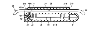
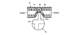
- FIG. 19 is an enlarged cross-sectional view showing a range enclosed by a two-dot chain line XIX in FIG. 18. It is an external view which shows a display part case.
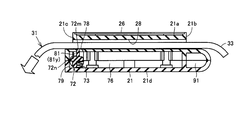
- FIG. 21 is a cross-sectional view showing the display unit case in FIG. 20 at the time of cuff removal. It is a side view which shows a motion of the cuff wound around a test subject's wrist at the time of cuff wearing.
- FIG. 14 is another side view showing the movement of the cuff wound around the subject's wrist when the cuff is attached.
- FIG. 12 is yet another side view showing the movement of the cuff wound around the subject's wrist when the cuff is attached.
- FIG. 26 is a side view showing the curler in FIG. 25 attached to the wrist. It is sectional drawing which represents typically a deformation
- FIG. 1 is a perspective view showing a usage form of a wrist-type sphygmomanometer according to an embodiment of the present invention.
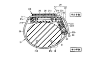
- FIG. 2 is a cross-sectional view showing the usage of the wrist-type sphygmomanometer as viewed from the direction indicated by arrow II in FIG.
- the basic structure of a wrist blood pressure monitor 100 shown in FIG. 1 will be described.
- wrist type sphygmomanometer 100 has a device body 110 and a cuff 31 as its main components. At the time of blood pressure measurement, the wrist type sphygmomanometer 100 is worn with the cuff 31 wound around the subject's wrist. The cuff 31 is generally worn on the wrist of the left hand.
- the device body 110 has a body case 20 and a display unit 26.
- the main body case 20 has a housing shape and makes an appearance of the apparatus main body 110.
- the display unit 26 is provided on the surface of the main body case 20.
- the display unit 26 displays the measurement result of the blood pressure value, the measurement result of the pulse rate, and the like using numerical values, graphs, and the like.
- a liquid crystal panel is used as the display unit 26, for example.
- the main body case 20 is provided integrally with the cuff 31.
- the cuff 31 is attached to the subject's wrist such that the main body case 20 is disposed on the circumference of the back side wrist of the hand.
- FIG. 3 is a cross-sectional view showing a range surrounded by a two-dot chain line III in FIG.
- the cuff 31 has a band-like outer shape whose longitudinal direction is the winding direction with respect to the wrist.
- the cuff 31 takes a tubular form in a state of being wound around the subject's wrist. That is, the circumferential direction of the cuff 31 having a tubular shape is the same as the circumferential direction around the wrist of the subject.
- the cuff 31 has an air bag 41 supplied with air, and a bag-like cover 36 for winding and fixing the air bag 41 around the wrist.
- the air bag 41 is housed inside the bag-like cover body 36.
- the air bag 41 is formed of a bag-like member formed using a resin sheet.
- An expansion and contraction space 45 is formed inside the air bag 41.
- the pressure of the inflation and deflation space 45 is a cuff pressure.
- the expansion and contraction space 45 is connected to a blood pressure measurement air system component 141 of the device main body 110 described later via a pipe (see FIG. 4).
- the cuff 31 further includes a curler 46 as a plate member that biases the air bladder 41 inward.
- the curler 46 has a substantially rectangular outer shape in the unfolded state.
- the curler 46 is disposed inside the bag-like cover body 36 so as to overlap the outside of the air bag 41 with respect to the subject's wrist.
- the curler 46 is formed of, for example, a resin material such as polypropylene (PP).
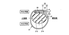
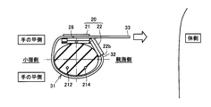
- the ulnar artery 212 and the radial artery 214 exist in the wrist cross section close to the palm side. With the cuff 31 wound around the subject's wrist, the air bladder 41 is arranged to cover the wrist surface on the palm side. At the time of blood pressure measurement, the air bladder 41 is inflated by air supply, and the ulnar artery 212 and the radial artery 214 are compressed by the inflated air bladder 41.
- FIG. 4 is a functional block diagram showing the configuration of the wrist type sphygmomanometer in FIG.
- the device body 110 is provided with a blood pressure measurement air-based component 141 for supplying or discharging air to the air bladder 41 contained in the cuff 31 through piping.
- the air system component 141 for blood pressure measurement is a pressure detection unit that detects the pressure in the air bladder 41, and a pressure sensor 142 as a sensor unit and a pump as an expansion and contraction mechanism unit 140 for inflating and contracting the air bladder 41. 143 and a valve 145.
- An oscillation circuit 147, a pump drive circuit 148, and a valve drive circuit 149 are provided in the device body 110 in association with the air pressure measurement air system component 141.
- the device body 110 includes a central processing unit (CPU) 150 for centrally controlling and monitoring each part, and a memory for storing various information such as a program that causes the CPU 150 to perform predetermined operations and measured blood pressure values. Power is supplied to the unit 170, the display unit 26 for displaying various information including blood pressure measurement results, the input unit 190 operated to input various instructions for measurement, the CPU 150, and each functional block A power supply unit 180 is provided.
- the CPU 150 also functions as a blood pressure value calculation unit for calculating a blood pressure value.
- the pressure sensor 142 detects the cuff pressure of the air bladder 41, and outputs a signal corresponding to the detected pressure to the oscillation circuit 147.
- the pump 143 supplies air to the air bladder 41 through piping.
- the valve 145 opens and closes when maintaining the pressure in the air bladder 41 or discharging the air in the air bladder 41.
- the oscillation circuit 147 outputs a signal of an oscillation frequency corresponding to the output value of the pressure sensor 142 to the CPU 150.
- the pump drive circuit 148 controls the drive of the pump 143 based on a control signal supplied from the CPU 150.
- the valve drive circuit 149 performs opening / closing control of the valve 145 based on a control signal supplied from the CPU 150.
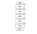
- FIG. 5 is a flow chart showing a flow of blood pressure measurement processing of the sphygmomanometer in FIG.
- the program according to the flowchart in FIG. 5 is stored in advance in the memory unit 170 shown in FIG. 4, and the CPU 150 reads out and executes this program from the memory unit 170 to perform the blood pressure measurement process.
- step S101 when the subject operates the power button of input unit 190 to turn on the power, wrist-type sphygmomanometer 100 is initialized (step S101).
- step S102 the CPU 150 starts driving of the pump 143 to gradually increase the cuff pressure of the air bladder 41 (step S102).
- the CPU 150 extracts pulse wave information based on the oscillation frequency obtained from the oscillation circuit 147. Then, the systolic blood pressure value (the highest blood pressure value) and the diastolic blood pressure value (the lowest blood pressure value) are calculated based on the extracted pulse wave information (step S103). This completes the measurement of the blood pressure value.
- the CPU 150 displays the calculated blood pressure value on the display unit 26 (step S104).
- the CPU 150 stops the pump 143.
- the valve 145 which has been closed is opened to exhaust the air of the air bladder 41 (step S105). Thereafter, the CPU 150 ends the operation after waiting for the subject's power-off command.
- the measurement method described above is based on a so-called pressurization measurement method of detecting a pulse wave when the air bladder 41 is pressurized, but a so-called decompression measurement method of detecting a pulse wave when the air bladder 41 is depressurized. It is of course also possible to adopt
- a main body case 20 is configured by combining a display unit side case 21 and a pump side case 22.
- the display unit side case 21 and the pump side case 22 are arranged side by side in the circumferential direction around the wrist.
- the display unit side case 21 is disposed at the center position of the back of the hand in the circumferential direction around the wrist.
- the display unit side case 21 is provided with a display unit 26.
- the display unit case 21 further accommodates a CPU 150, a memory unit 170, an input unit 190, a power supply unit 180, and various circuits 147 to 149.
- the blood pressure measurement air system component 141 that is, the pump 143, the valve 145, and the pressure sensor 142 are housed in the pump case 22.
- the pressure sensor 142 may be accommodated in the display unit side case 21.
- the display unit side case 21 has a substantially rectangular parallelepiped shape having a main surface 21a, a bottom surface 21d, and side surfaces 21b and 21c.
- the main surface 21 a is disposed on the outer peripheral side on the circumference of the wrist.
- the display unit 26 is provided on the main surface 21 a.
- the bottom surface 21 d is disposed on the inner peripheral side on the circumference of the wrist, and faces the opposite side to the main surface 21 a.
- the bottom surface 21 d is disposed to face the wrist surface on the back side of the hand.
- the side surface 21 b and the side surface 21 c extend in the direction connecting the main surface 21 a and the bottom surface 21 d and face in the circumferential direction of the cuff 31.
- the side surface 21 b and the side surface 21 c face each other in the circumferential direction of the cuff 31.
- An insertion hole 28 is formed in the main body case 20.
- the insertion hole 28 is formed in the display unit side case 21.
- the insertion hole 28 is formed at a position separated from the bottom surface 21 d.
- the insertion hole 28 is formed between the main surface 21 a and the bottom surface 21 d.
- the insertion hole 28 is formed to penetrate the display unit side case 21 between the side surface 21 c and the side surface 21 b. With the cuff 31 attached to the subject's wrist, the insertion hole 28 extends along the circumferential tangential direction around the wrist.
- the open cross-sectional area of the insertion hole 28 is larger than the cross-sectional area of the cuff 31 when the cuff 31 is cut by a plane orthogonal to the longitudinal direction.
- the pump side case 22 has a substantially rectangular parallelepiped shape having a main surface 22a, a bottom surface 22d and side surfaces 22b and 22c.
- the main surface 22a is disposed on the outer peripheral side on the circumference of the wrist.
- the bottom surface 22 d is disposed on the inner peripheral side on the circumference of the wrist, and faces the opposite side to the main surface 22 a.
- the bottom surface 22 d is disposed to face the wrist surface on the back side of the hand.
- the side surface 22 b and the side surface 22 c extend in the direction connecting the main surface 22 a and the bottom surface 22 d and face the circumferential direction of the cuff 31.
- the side surface 22 b and the side surface 22 c face each other in the circumferential direction of the cuff 31.
- the display unit side case 21 and the pump side case 22 are arranged such that the side surface 21 b and the side surface 22 c face each other.
- the display unit side case 21 and the pump case 22 respectively have a connecting portion 91 and a connecting portion 92.
- the connecting portion 91 and the connecting portion 92 are provided on the side surface 21 b and the side surface 22 c, respectively.
- the display unit side case 21 and the pump side case 22 are connected to each other through connecting portions 91 and 92.
- the cuff 31 has one end 32 and the other end 33 at both ends in the longitudinal direction.
- One end 32 of the cuff 31 is fixed to the main body case 20.
- One end 32 of the cuff 31 is fixed to the pump case 22.
- One end 32 of the cuff 31 is fixed to the side surface 22 b of the pump case 22.
- the main body case 20 has a locking mechanism 71.
- the cuff 31 is wound around the wrist starting from one end 32 fixed to the main body case 20, and the other end 33 is inserted into the insertion hole 28.
- the locking mechanism portion 71 is provided to be able to lock the other end 33 of the cuff 31 inserted into the insertion hole 28.
- the other end 33 of the cuff 31 is locked to the display unit side case 21 of the main body case 20 by the locking mechanism unit 71, whereby the cuff 31 is held in a state of being wound around the subject's wrist.
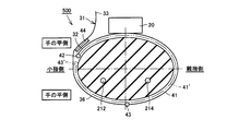
- the air bladder 41 is not disposed between the main body case 20 and the wrist in a state where the cuff 31 is wound around the wrist.
- connection structure of the display unit side case 21 and the pump side case 22 and the structure of the locking mechanism unit 71 will be described in detail in a second embodiment.
- FIG. 6 is a cross-sectional view showing a usage pattern of a wrist-type sphygmomanometer for comparison when the wrist circumference of the subject is small.
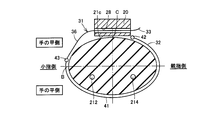
- FIG. 7 is a cross-sectional view showing a usage form of a wrist-type sphygmomanometer for comparison when the wrist circumference of the subject is large.
- a wrist type sphygmomanometer 500 for comparison having a body case 20 and a cuff 31 is schematically shown in the drawings.
- the cuff 31 is attached to the wrist in a use form in which the main body case 20 is disposed on the wrist side of the thumb side.
- a hook and loop fastener 44 is provided at one end 32 of the cuff 31 .
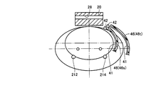
- the cuff 31 is wound around the subject's wrist, and the bag-like cover body 36 on the other end 33 side is joined to the hook-and-loop fastener 44.
- the air bladder 41 passes from the end 42 located on the back side of the hand to the palm side and is adjacent to the end 42 inside the bag-like cover 36 Extends to the end 43 located. Further, as shown in FIG. 7, when the subject's wrist circumference is large, the air bladder 41 passes from the end portion 42 located on the back side of the hand to the wrist side portion on the thumb side inside the bag-like cover body 36 It extends to an end 43 located on the wrist side on the little finger side. In any case, the air bladder 41 is provided to cover the palm side wrist surface.
- FIG. 8 is a cross-sectional view showing another use of the wrist-type sphygmomanometer for comparison in FIGS. 6 and 7 when the wrist circumference of the subject is large.
- the wrist type sphygmomanometer 500 for comparison in FIGS. 6 and 7 the case where the cuff is attached such that the main body case 20 is disposed on the back surface of the hand is shown. .
- the air bladder 41 passes from the end 42 located on the wrist side on the little finger side to the wrist surface on the back side of the hand, and the end 42 located on the palm side wrist surface.
- the air bladder 41 can not be disposed so as to entirely cover the wrist surface on the palm side.
- FIG. 9 is a cross-sectional view showing a usage form of a wrist-type sphygmomanometer for comparison in FIG. 8 when the wrist circumference of the subject is small.
- the figure shows the case where air bag 41 'set in wrist type sphygmomanometer 500 in FIG. 8 is applied to a subject with a small wrist circumference.
- the air bag 41 ' is provided to encircle the wrist from the end 42 located on the wrist side on the little finger side and further to overlap on the outer periphery of the air bag 41' wound around the wrist.
- the wrist type sphygmomanometer 500 for comparison, even if the usage case in which the main body case 20 is placed on the back surface of the hand is adopted, it can be used for both large and small wrists.
- the structure of the cuff 31 can not be set.
- FIG. 10 is a cross-sectional view showing a usage form of the wrist-type sphygmomanometer in FIG. 1 when the wrist circumference of the subject is small.
- FIG. 11 is a cross-sectional view showing a usage pattern of the wrist-type sphygmomanometer in FIG. 1 when the wrist circumference of the subject is large.
- one end 32 of the cuff 31 is fixed to the main body case 20, and at the time of attachment of the cuff 31 to the wrist, The other end 33 of the cuff 31 is locked by a locking mechanism 71 (see FIG. 2) provided on the main body case 20. Further, the air bag 41 is not disposed between the main body case 20 and the wrist in a state where the cuff 31 is wound around the wrist.
- the wrist-type sphygmomanometer 100 capable of covering the entire wrist surface of the palm side by the air bladder 41 regardless of whether the subject's wrist circumference is small or large. Even when the total length of the air bag 41 is set to a length capable of covering the entire wrist surface on the palm side when the subject's wrist circumference is large, when the subject's wrist circumference is small, The wrist type sphygmomanometer 100 in which the tightening of the wrist by the cuff 31 is not prevented can be realized.
- the center position of the wrist surface on the back side of the hand (the position on the back side of the hand) of the 1 ⁇ 4 circumferential position (position A in FIG. 10) of the minimum wrist circumference assumed to be measured The end 42 is disposed on the position C) side in FIG. 10, and the position C in FIG. 11 is higher than the 3 ⁇ 4 circumferential position (position B in FIG. 11) of the maximum wrist circumference assumed for measurement
- the overall length and arrangement of the air bladder 41 is set such that the end 43 is located on the) side.
- the other end 33 of the cuff 31 is inserted into the insertion hole 28 formed in the main body case 20. According to such a configuration, the occurrence of interference between the cuff 31 and the main body case 20 with the expansion of the air bladder 41 is eliminated. Further, the cuff 31 does not block the visual recognition of the display unit 26.
- the wrist type sphygmomanometer 100 according to the first embodiment of the present invention described above is a tube by being wound around the subject's wrist.
- the cuff 31 has an air bladder 41 as an inflatable and contractable fluid bag to which air as fluid is supplied.
- the expansion and contraction mechanism section 140 inflates and contracts the air bag 41.
- the main body case 20 accommodates the expansion and contraction mechanism unit 140.
- the main body case 20 has a locking mechanism portion 71 that locks the other end 33 in the circumferential direction of the cuff 31 and holds the cuff 31 in a state of being wound around the wrist.
- the wrist circumference is taken while using the cuff 31 in which the main body case 20 is disposed on the circumference of the back side wrist of the hand. It is possible to realize a wrist-type sphygmomanometer capable of dealing with people from large to small. Even if the person is using wrist-type sphygmomanometer 100 for the first time, cuff 31 can be naturally worn in the correct position by the use form of cuff 31 arranged on the circumference of the wrist on the back side of the hand. .
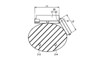
- FIG. 12 is a side view showing the main body case disposed on the circumference of the wrist.
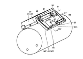
- FIG. 13 is a perspective view showing the main body case in FIG.
- display unit case 21 and pump case 22 each have a connecting portion 91 and a connecting portion 92.
- the connecting portion 91 and the connecting portion 92 support a shaft extending along the axial direction (axial direction of the central axis 61) of the cuff 31 having a tubular shape, and rotatably support the shaft around the axis. It is comprised by the combination with a receiving part.
- the display unit side case 21 and the pump case 22 are rotatably coupled about the central shaft 61 via the coupling portions 91 and 92.
- the display case 21 and the pump case 22 conform to the shape of the subject's wrist. To rotate.
- the display unit side case 21 and the pump side case 22 can be arranged on the circumference of the wrist along the shape of the wrist.
- the pump case 22 has a total length smaller than that of the display unit case 21 (L2 ⁇ L1).
- the shape of the wrist has a large length in the width direction as viewed from the back side of the hand and a small length in the thickness direction.
- the display unit side case 21 and the pump side case 22 are approximated more like a wrist by the relationship of L2 ⁇ L1. It can be arranged.
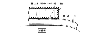
- FIG. 14 is a cross-sectional view showing the main body case along the line XIV-XIV in FIG. Referring to FIGS. 13 and 14, pump 143 and pressure sensor 142 are accommodated inside pump case 22.
- the pump 143 and the pressure sensor 142 respectively have an air pipe 66 as a first pipe line and an air pipe 67 as a second pipe line.
- the pump 143 is connected to the air bladder 41 through the air pipe 66, and the pressure sensor 142 is connected to the air bladder 41 through the air pipe 67.
- the air tube 66 and the air tube 67 are provided so as to open to the side surface 22 b of the pump case 22.
- the side surface 22 b is a side surface disposed at an end portion of the main body case 20 in the circumferential direction of the cuff 31 having a tubular shape.
- FIG. 15 is a cross-sectional view showing a main body case for comparison.
- an air pipe 66 is provided so as to open at the bottom surface 22 d of the pump case 22.
- the cuff 31 is interposed between the wrist surface and the pump case 22 in a state of being attached to the wrist. In such a configuration, there arises a problem that the protruding height of the pump case 22 from the surface of the wrist is increased.
- the air tube 66 and the air tube 67 are provided so as to open at the side surface 22b of the pump case 22. Therefore, it is not necessary to interpose the cuff 31 between the wrist surface and the pump case 22. Therefore, it is possible to make the pump case 22 thinner. In this case, for example, even if the wrist type sphygmomanometer 100 wears the cuff 31 for 24 hours in order to continuously measure the blood pressure value, the subject can easily feel the cuff without discomfort. 31 can continue to wear.
- the main body case 20 has a split structure including the display portion side case 21 and the pump side case 22, and an expansion and contraction mechanism for supplying air to the air bladder 41.
- the portion 140 is accommodated inside the pump case 22. According to such a configuration, although the main body case 20 is disposed on the wrist surface on the back side of the hand, the expansion / contraction mechanism portion 140 accommodated in the pump case 22 is disposed at a position closer to the palm side Can. As a result, the volume of the air bladder 41 can be set small, and the pump 143 can be miniaturized accordingly.
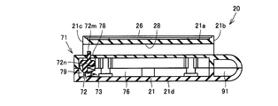
- FIG. 16 is a cross-sectional view showing the display unit side case.
- a housing space 76 is formed between the bottom surface 21d and the insertion hole 28.
- a receiving portion 79 for supporting a stopper portion 72 described later is formed in the housing space 76.
- An opening 78 is formed in the display unit side case 21 so as to communicate between the housing space 76 and the insertion hole 28.
- the locking mechanism 71 is housed in the housing space 76.
- the locking mechanism portion 71 is disposed closer to the side surface 21 c, which is a side into which the other end 33 of the cuff 31 is inserted, of the side surface 21 b and the side surface 21 c.
- the locking mechanism 71 has a stopper 72 and a spring 73 as its components.
- the stopper portion 72 has a pressing portion 72m and a base portion 72n as its component parts.
- the base portion 72 n is formed to have a cylindrical shape.
- the base portion 72 n is disposed in the housing space 76.
- the pressing portion 72m is formed to enter the insertion hole 28 from the base portion 72n through the opening 78.
- the base portion 72 n is supported by the receiving portion 79 in the housing space 76.
- the base portion 72 n is rotatably supported by the receiving portion 79 such that the posture of the pressing portion 72 m changes.
- the spring portion 73 is provided in contact with the base portion 72 n.
- the spring portion 73 is disposed on the opposite side of the insertion hole 28 with respect to the base portion 72 n.
- the spring portion 73 is provided to apply an elastic force in a direction approaching the insertion hole 28 to the stopper portion 72.
- the pressing portion 72m is provided so as to protrude from the opening 78 into the inside of the insertion hole 28.
- FIG. 17 is a cross-sectional view showing the display unit side case in FIG. 16 at the time of cuff insertion.
- FIG. 18 is a cross-sectional view showing the display unit side case in FIG. 16 after the cuff is inserted.
- the locking mechanism 71 allows movement of the cuff 31 inserted in the insertion hole 28 in the tightening direction and restricts movement in the loosening direction, and can lock the other end 33 of the cuff 31. It is provided like.
- the subject can attach the cuff 31 to the wrist by a series of operations of inserting the cuff 31 into the insertion hole 28 and slidingly moving the cuff 31 in the tightening direction.
- the structure of the locking mechanism 71 is not limited to the structure shown in the drawing, and may be a structure using a general one-way clutch, for example.
- FIG. 19 is an enlarged cross-sectional view of the area enclosed by the two-dot chain line XIX in FIG.
- the pressing portion 72m is formed to have a length equal to or greater than that of the air bladder 41 in the width direction of the insertion hole 28 (the depth direction of the paper surface shown in FIG. 18).
- the expansion / contraction space 45 in the air bladder 41 is a space 45p on one end 32 side of the cuff 31 and a space on the other end 33 side of the cuff 31 inside the cuff 31. It is divided into 45q.
- the locking mechanism portion 71 is disposed on the side closer to the side surface 21 c among the side surface 21 b and the side surface 21 c. In the state where the cuff 31 is inserted into the insertion hole 28, the side surface 21c is located on the end 32 side of the cuff 31, so that the above effect can be more effectively exhibited.
- FIG. 20 is an external view showing a display unit case.
- FIG. 21 is a cross-sectional view showing the display unit case in FIG. 20 at the time of cuff removal.
- locking mechanism 71 further includes a release portion 81.
- the release unit 81 has an operation unit 81x and a moving unit 81y as its component parts.
- the operation unit 81 x is provided so as to be exposed to the outside of the display unit side case 21 so that the subject can perform an operation.
- the operation unit 81x is also provided on the opposite side surface of the display unit side case 21 shown in FIG.
- the moving unit 81y is disposed in the housing space 76.
- the moving portion 81 y is coupled to the stopper portion 72. More specifically, the moving portion 81y is provided so as to abut on the base portion 72n between the insertion hole 28 and the base portion 72n.
- the moving unit 81y moves in a direction away from the insertion hole 28.
- the stopper portion 72 is pushed into the housing space 76 against the elastic force of the spring portion 73.
- the pressing of the cuff 31 by the pressing portion 72m is released, and the cuff 31 can be pulled out from the insertion hole 28.
- the subject can immediately release the restraint of the wrist by the cuff 31 even in an emergency at the time of blood pressure measurement.
- 22 to 24 are side views showing the movement of the cuff wound around the subject's wrist when the cuff is attached.
- one end 32 of cuff 31 is the thumb of the subject when body case 20 is arranged on the circumference of the back side wrist of the hand. It is connected to the end of the main body case 20 on the side, that is, the side surface 22 b of the pump case 22.
- the subject when the subject wears the cuff 31, as shown in FIG. 22, the subject first wraps around the wrist while keeping the cuff 31 away from the near side of the subject's body. Then, as shown in FIGS. 23 and 24, the other end 33 of the cuff 31 is inserted into the insertion hole 28, and the cuff 31 is drawn to the near side of the subject's body. According to such an operation process, the subject can easily handle the cuff 31, and therefore, the operability at the time of wearing the cuff 31 can be improved.
- the other end 33 of the cuff 31 may be provided with a stopper, and the other end 33 of the cuff 31 may be inserted into the insertion hole 28 at all times.
- the subject may draw the other end 33 of the cuff 31 toward the near side of the body after placing the tubular cuff 31 around the wrist.
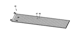
- FIG. 25 is a perspective view showing a curler included in a cuff.
- FIG. 26 is a side view showing the curler in FIG. 25 attached to the wrist.
- the curler 46 has a surface 46b facing the wrist surface and a surface 46a disposed on the back of the surface 46b, with the cuff 31 attached to the wrist.
- a plurality of grooves 47 are formed in the curler 46.
- the plurality of grooves 47 extend along the axial direction of the cuff 31 in the form of a cylindrical shape.
- the plurality of grooves 47 are formed to be recessed from the surface 46a.
- Grooves 47 and projections 48 are repeatedly formed in the surface 46 a in the longitudinal direction of the cuff 31.
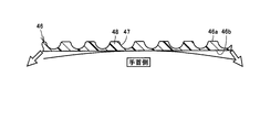
- FIG. 27 is a cross-sectional view schematically showing the deformation of the curler when the wrist circumference is small and large.
- the curvature of curler 46 differs greatly between the small and large wrist circumferences as shown in the figure. In this case, if the flexibility of the curler 46 is not sufficient, the curler 46 can not be curved corresponding to both the case where the wrist circumference is small and the case where the wrist circumference is large.
- the curlers 46 are easily curved in accordance with the shape of the wrist by forming a plurality of grooves 47 in the curlers 46. It can be done. Thereby, the cuff 31 can be fitted to the wrist without creating a gap between the cuff 31 and the wrist surface. Further, when the cuff 31 is not in use, the cuff 31 can be thinly folded, so that the storability of the cuff 31 can be improved.
- the present invention is mainly applied to a wrist-type sphygmomanometer used at home for the purpose of self-management of blood pressure and the like.
Landscapes
- Health & Medical Sciences (AREA)
- Life Sciences & Earth Sciences (AREA)
- Cardiology (AREA)
- Vascular Medicine (AREA)
- Engineering & Computer Science (AREA)
- Medical Informatics (AREA)
- Physics & Mathematics (AREA)
- Ophthalmology & Optometry (AREA)
- Biophysics (AREA)
- Pathology (AREA)
- Dentistry (AREA)
- Biomedical Technology (AREA)
- Heart & Thoracic Surgery (AREA)
- Physiology (AREA)
- Molecular Biology (AREA)
- Surgery (AREA)
- Animal Behavior & Ethology (AREA)
- General Health & Medical Sciences (AREA)
- Public Health (AREA)
- Veterinary Medicine (AREA)
- Measuring Pulse, Heart Rate, Blood Pressure Or Blood Flow (AREA)
Abstract
手首式血圧計は、空気が供給される膨縮可能な空気袋(41)を有し、被験者の手首に巻き回されることにより筒形状の形態をとるカフ(31)と、空気袋(41)を膨縮させるための膨縮機構部と、カフ(31)が手首に巻き回わされた状態で手首の周上に配置される本体ケース(20)とを備える。本体ケース(20)は、膨縮機構部を収容する。本体ケース(20)には、カフ(31)の周方向における一端(32)が固定される。本体ケース(20)は、カフ(31)の周方向における他端(33)を係止し、カフ(31)を手首に巻き回された状態に保持する係止機構部(71)を有する。このような構成によれば、正しい使用形態によりカフが装着される手首式血圧計を提供することができる。
Description
この発明は、一般的には、手首式血圧計に関し、より特定的には、被験者の手首にカフを装着して血圧測定を実施する手首式血圧計に関する。
従来の手首式血圧計に関して、たとえば、特開2003-24286号公報には、手首部に存在する筋、腱および骨の影響を受けることなく、手首部に位置する動脈を確実に圧迫することを目的とした手首式血圧計用カフが開示されている(特許文献1)。特許文献1に開示された手首式血圧計用カフは、加圧ポンプから送り出される空気が溜められるとともに、手首部の動脈を圧迫するために用いられる、第1空気袋と、第1空気袋と手首部との間に位置し、第1空気袋よりも伸縮性の高い材質からなる第2空気袋とを備える。
上述の特許文献に開示されるように、被験者の手首にカフを装着して血圧測定を実施する手首式血圧計が広く利用されている。このような手首式血圧計は、カフ内部に収容される空気袋と、その空気袋に空気を供給するためのポンプが設けられる筐体とを備える。血圧測定時、ポンプから空気袋に空気が供給されることによって、手の平側の手首内に存在する、とう骨動脈および尺骨動脈という2本の動脈を圧迫する。
一方、手首式血圧計は、手首周の細い人から太い人まで幅広く対応する必要があるため、手首周方向における空気袋の中心が、圧迫すべき動脈がある手の平側に配置されるのが一般的である。この場合、ポンプが設けられる筐体も手の平側に配置されたり、手の側部側に配置されたりすることになる。
しかしながら、手首式血圧計を初めて使用する人は、手首に装着するものとして馴染みがある腕時計と同じように、筐体を手の甲側に配置してカフを手首に装着するおそれがある。この場合、被験者の動脈が空気袋によって適切に圧迫されず、正確な血圧測定を実施することができないという問題が生じる。
そこでこの発明の目的は、上記の課題を解決することであり、正しい使用形態によりカフが装着される手首式血圧計を提供することである。
この発明に従った手首式血圧計は、被験者の手首に巻き回されることにより筒形状の形態をとるカフと、膨縮機構部と、カフが手首に巻き回わされた状態で手首の周上に配置される筐体とを備える。カフは、流体が供給される膨縮可能な流体袋を有する。膨縮機構部は、流体袋を膨縮させる。筐体は、膨縮機構部を収容する。筐体には、カフの周方向における一端が固定される。筐体は、カフの周方向における他端を係止し、カフを手首に巻き回された状態に保持する係止機構部を有する。
このように構成された手首式血圧計によれば、カフの周方向における一端が筐体に固定されているとともに、手首へのカフの装着時、カフの周方向における他端が筐体が有する係止機構部により係止される。このような構成において、筐体が手の甲側の手首上に配置されるカフの使用形態を想定すると、カフは、手の甲側を始点に手首の周りを周回し、再び手の甲側に向かう形態となる。これにより、被験者の手首周長が大きいか小さいかにかかわらず、カフが有する流体袋を、圧迫すべき動脈が存在する手の平側の手首上に、より確実に配置することができる。
結果、被験者が最も馴染みがあると考えられる手の甲側に筐体を配置するカフの使用形態をとることが可能となり、この使用形態において、被験者は、正しい使用形態によりカフを装着することができる。
また好ましくは、流体袋は、カフが手首に巻き回わされた状態で、筐体と手首との間に配置されない。
このように構成された手首式血圧計によれば、被験者の手首周長が大きいか小さいかにかかわらず、流体袋を、圧迫すべき動脈が存在する手の平側の手首上により確実に配置することができる。
また好ましくは、手首式血圧計は、測定された血圧値を表示する表示部をさらに備える。筐体は、表示部が設けられる第1筐体部と、第1筐体部に対してカフの周方向にずれた位置に配置される第2筐体部とを有する。第2筐体部は、膨縮機構部を収容し、カフの周方向における一端が固定される。
このように構成された手首式血圧計によれば、表示部が設けられた第1筐体部を手の甲側に配置するカフの使用形態により、被験者は、正しい使用形態によりカフを装着することができる。また、膨縮機構部は、第1筐体部に対してカフの周方向にずれた位置に配置された第2筐体部に設けられている。これにより、流体袋の容積を小さく設定し、膨縮機構部を小型化することが可能となる。これに伴って、筐体を薄型化することが可能となるため、被験者は、違和感なく長時間に渡ってカフを装着することができる。
また好ましくは、第1筐体部と第2筐体部とは、カフの軸方向に沿った軸を中心に互いに回動可能に連結される。
このように構成された手首式血圧計によれば、第1筐体部および第2筐体部を、手首の形状に沿わせて手首の周上に配置することができる。これにより、筐体と手首との間に隙間が生じることを抑制し、流体袋の膨張に伴う圧迫力をより確実に手首に伝えることができる。
また好ましくは、カフの周方向において、第2筐体部は、1筐体部よりも小さい全長を有する。
このように構成された手首式血圧計によれば、表示部が設けられた第1筐体部を手の甲側に配置するカフの使用形態において、第1筐体部および第2筐体部を手首の形状に沿わせて手首の周上に配置することができる。
また好ましくは、膨縮機構部は、流体袋に接続され、流体が流通する第1管路を含む。第1管路は、カフの周方向における筐体の端部に開口するように設けられる。また好ましくは、手首式血圧計は、筐体に収容され、流体袋内の圧力を検出するセンサ部をさらに備える。センサ部は、流体袋に接続され、流体が流通する第2管路を有する。第2管路は、カフの周方向における筐体の端部に開口するように設けられる。
このように構成された手首式血圧計によれば、筐体を薄型化することにより、被験者は、違和感なく長時間に渡ってカフを装着することができる。
また好ましくは、筐体は、カフが手首に巻き回わされた状態で手首表面と向かい合う底面を有する。筐体には、底面から距離を隔てた位置において筐体を貫通し、カフの周方向における他端が挿入される挿入孔が形成される。
このように構成された手首式血圧計によれば、筐体とカフの周方向における他端との干渉に起因して、カフの装着が妨げられることを回避できる。
また好ましくは、係止機構部は、ストッパ部を含む。ストッパ部は、挿入孔に挿入されたカフの締め付け方向の移動を許容するとともに緩み方向の移動を規制し、カフの周方向における他端を係止するように設けられる。
このように構成された手首式血圧計によれば、被験者は、カフを挿入孔に挿入し、その締め付け方向に引っ張るという一連の操作によって、カフの周方向における他端を筐体に対して係止させることができる。このため、カフ装着時の操作性を向上させることができる。
また好ましくは、ストッパ部は、カフの係止時に流体袋を押圧する。ストッパ部による押圧によって、流体袋の内部がカフの一端側の空間と他端側の空間とに区画される。
このように構成された手首式血圧計によれば、血圧測定時に、流体袋内部の、カフの一端側の空間にのみ流体を供給すればよくなるため、測定時間を短縮することができる。
また好ましくは、係止機構部は、解除部をさらに含む。解除部は、ストッパ部に連結され、ストッパ部によるカフの係止を解除するように設けられる。
このように構成された手首式血圧計によれば、手首に装着されたカフを取り外す際の操作性を向上させることができる。
また好ましくは、筐体を手の甲側の手首の周上に配置した場合に、カフの周方向における一端が、被験者の親指側の筐体の端部に接続される。
このように構成された手首式血圧計によれば、カフの装着時、手の甲側が上方を向くように手首を支持した場合に、カフは、体の近い側から遠い側に巻き回され、さらに、挿入孔を通されて体の近い側に向けて引っ張られる。このため、カフ装着時の操作性を向上させることができる。
また好ましくは、カフは、手首に巻き回された状態で流体袋の外側に配置される板部材をさらに有する。その板部材には、カフの軸方向に沿って延びる複数の溝が形成される。
このように構成された手首式血圧計によれば、被験者の手首周長が大きいか小さいかにかかわらず、板部材の形状を手首の形状に沿わせることができる。
また好ましくは、カフは、手首に対して、筐体が手の甲側の手首の周上に配置されるように装着される。
このように構成された手首式血圧計によれば、被験者にとって最も馴染みがあると考えられる手の甲側に筐体が配置されるため、被験者は、正しい使用形態によりカフを装着することができる。
以上に説明したように、この発明に従えば、正しい使用形態によりカフが装着される手首式血圧計を提供することができる。
この発明の実施の形態について、図面を参照して説明する。なお、以下で参照する図面では、同一またはそれに相当する部材には、同じ番号が付されている。
(実施の形態1)
図1は、この発明の実施の形態における手首式血圧計の使用形態を示す斜視図である。図2は、図1中の矢印IIに示す方向から見た手首式血圧計の使用形態を示す断面図である。本実施の形態では、図1中に示す手首式血圧計100の基本構造について説明する。
図1は、この発明の実施の形態における手首式血圧計の使用形態を示す斜視図である。図2は、図1中の矢印IIに示す方向から見た手首式血圧計の使用形態を示す断面図である。本実施の形態では、図1中に示す手首式血圧計100の基本構造について説明する。
図1および図2を参照して、手首式血圧計100は、その主要な構成部品として、装置本体110およびカフ31を有する。血圧測定時、手首式血圧計100は、カフ31が被験者の手首に巻き回された状態で装着される。カフ31は、一般的に、左手の手首に装着される。
装置本体110は、本体ケース20および表示部26を有する。本体ケース20は、筐体形状を有し、装置本体110の外観をなす。表示部26は、本体ケース20の表面に設けられている。表示部26には、血圧値の測定結果や脈拍数の測定結果などが、数値やグラフなどを用いて表示される。表示部26としては、たとえば、液晶パネルが利用される。
本体ケース20は、カフ31と一体に設けられている。本実施の形態における手首式血圧計100においては、カフ31は、被験者の手首に対して、本体ケース20が手の甲側の手首の周上に配置されるように装着される。
図3は、図2中の2点鎖線IIIに囲まれた範囲を示す断面図である。図1から図3を参照して、カフ31は、手首に対する巻き付け方向を長手方向とする帯状の外形を有する。カフ31は、被験者の手首に巻き回された状態で筒形状の形態をとる。すなわち、筒形状の形態をとるカフ31の周方向は、被験者の手首周りの周方向と同一方向である。
カフ31は、空気が供給される空気袋41と、空気袋41を手首に巻き付けて固定するための袋状カバー体36とを有する。空気袋41は、袋状カバー体36の内部に収容されている。空気袋41は、樹脂シートを用いて形成された袋状の部材からなる。空気袋41の内部には、膨縮空間45が形成されている。膨縮空間45の圧力が、カフ圧である。膨縮空間45は、後述する装置本体110の血圧測定用エア系コンポーネント141と、配管を介して接続されている(図4参照のこと)。
カフ31は、空気袋41を内側に向けて付勢する、板部材としてのカーラ46をさらに有する。カーラ46は、展開した状態において略矩形状の外形を有する。カーラ46は、袋状カバー体36の内部で、被験者の手首に対して空気袋41の外側に重なって配置されている。カーラ46は、たとえばポリプロピレン(PP)等の樹脂材料から形成されている。
手の平側に近い手首断面には、尺骨動脈212およびとう骨動脈214が存在する。カフ31が被験者の手首に巻き回された状態で、空気袋41は、手の平側の手首表面を覆うように配置される。血圧測定時、空気が供給されることによって空気袋41が膨張し、その膨張した空気袋41によって尺骨動脈212およびとう骨動脈214が圧迫される。
次に、手首式血圧計100の主要な機能ブロックの構成について説明する。図4は、図1中の手首式血圧計の構成を示す機能ブロック図である。
図4を参照して、装置本体110には、カフ31に内包された空気袋41に配管を通じて空気を供給または排出するための血圧測定用エア系コンポーネント141が設けられている。血圧測定用エア系コンポーネント141は、空気袋41内の圧力を検出する圧力検出手段である、センサ部としての圧力センサ142と、空気袋41を膨縮させるための膨縮機構部140としてのポンプ143および弁145とから構成されている。装置本体110には、血圧測定用エア系コンポーネント141に関連して、発振回路147、ポンプ駆動回路148および弁駆動回路149が設けられている。
装置本体110には、各部を集中的に制御および監視するためのCPU(Central Processing Unit)150と、CPU150に所定の動作をさせるプログラムや測定された血圧値などの各種情報を記憶するためのメモリ部170と、血圧測定結果を含む各種情報を表示するための表示部26と、測定のための各種指示を入力するために操作される入力部190と、CPU150および各機能ブロックに電力を供給するための電源部180とが設けられている。CPU150は、血圧値を算出するための血圧値算出手段としても機能する。
圧力センサ142は、空気袋41のカフ圧を検出し、検出した圧力に応じた信号を発振回路147に出力する。ポンプ143は、配管を通じて空気袋41に空気を供給する。弁145は、空気袋41内の圧力を維持したり、空気袋41内の空気を排出したりする際に開閉する。発振回路147は、圧力センサ142の出力値に応じた発振周波数の信号をCPU150に出力する。ポンプ駆動回路148は、ポンプ143の駆動をCPU150から与えられる制御信号に基づいて制御する。弁駆動回路149は、弁145の開閉制御をCPU150から与えられる制御信号に基づいて行なう。
次に、手首式血圧計100における血圧測定処理の流れについて説明する。図5は、図1中の血圧計の血圧測定処理の流れを示すフローチャートである。
図5中のフローチャートに従うプログラムは、図4において示したメモリ部170に予め記憶されており、CPU150がメモリ部170からこのプログラムを読出して実行することにより、血圧測定処理が実施される。
図4および図5を参照して、被験者が入力部190の電源ボタンを操作して電源をオンにすると手首式血圧計100の初期化がなされる(ステップS101)。次に、測定可能状態になると、CPU150はポンプ143の駆動を開始し、空気袋41のカフ圧を徐々に上昇させる(ステップS102)。
カフ圧が徐々に上昇する過程において、CPU150が発振回路147から得られる発振周波数に基づき脈波情報を抽出する。そして、抽出された脈波情報により収縮期血圧値(最高血圧値)および拡張期血圧値(最低血圧値)を算出する(ステップS103)。これにより、血圧値の測定が完了される。
ステップS103において血圧値が算出されると、CPU150は、算出された血圧値を表示部26に表示する(ステップS104)。カフ圧が血圧測定のために必要な所定のレベルにまで達すると、CPU150はポンプ143を停止する。次いで、閉じていた弁145を開いて、空気袋41の空気を排気する(ステップS105)。その後、CPU150は、被験者の電源オフの指令を待ってその動作を終了する。
なお、以上において説明した測定方式は、空気袋41の加圧時に脈波を検出するいわゆる加圧測定方式に基づいたものであるが、空気袋41の減圧時に脈波を検出するいわゆる減圧測定方式を採用することも当然に可能である。
次に、手首式血圧計100の基本構造についてより詳細な説明を行なう。
図1から図4を参照して、本体ケース20は、表示部側ケース21およびポンプ側ケース22が組み合わさって構成されている。表示部側ケース21とポンプ側ケース22とは、手首周りの周方向に並んで配置されている。本実施の形態では、カフ31が被験者の手首に装着された状態で、表示部側ケース21が手首周りの周方向における手の甲の中心位置に配置されている。
図1から図4を参照して、本体ケース20は、表示部側ケース21およびポンプ側ケース22が組み合わさって構成されている。表示部側ケース21とポンプ側ケース22とは、手首周りの周方向に並んで配置されている。本実施の形態では、カフ31が被験者の手首に装着された状態で、表示部側ケース21が手首周りの周方向における手の甲の中心位置に配置されている。
表示部側ケース21には、表示部26が設けられている。表示部側ケース21には、さらに、CPU150、メモリ部170、入力部190、電源部180、各種回路147~149が収容されている。ポンプ側ケース22には、血圧測定用エア系コンポーネント141、すなわち、ポンプ143、弁145および圧力センサ142が収容されている。なお、圧力センサ142は、表示部側ケース21に収容されてもよい。
表示部側ケース21は、主面21a、底面21dおよび側面21b,21cを有する略直方体形状を有する。
カフ31が被験者の手首に装着された状態で、主面21aは、手首の周上の外周側に配置される。主面21aには、表示部26が設けられている。底面21dは、手首の周上の内周側に配置され、主面21aとは反対側に面する。底面21dは、手の甲側の手首表面と向かい合って配置される。側面21bおよび側面21cは、主面21aと底面21dとを結ぶ方向に延在し、カフ31の周方向に面する。側面21bおよび側面21cは、カフ31の周方向において互いに反対側に面する。
本体ケース20には、挿入孔28が形成されている。挿入孔28は、表示部側ケース21に形成されている。挿入孔28は、底面21dから距離を隔てた位置に形成されている。挿入孔28は、主面21aと底面21dとの間に形成されている。挿入孔28は、側面21cと側面21bとの間で表示部側ケース21を貫通するように形成されている。カフ31が被験者の手首に装着された状態で、挿入孔28は、手首周りの周方向の接線方向に沿って延伸する。挿入孔28の開口断面積は、カフ31をその長手方向に直交する平面により切断した場合のカフ31の断面積よりも大きくなる。
ポンプ側ケース22は、主面22a、底面22dおよび側面22b,22cを有する略直方体形状を有する。主面22aは、手首の周上の外周側に配置される。底面22dは、手首の周上の内周側に配置され、主面22aとは反対側に面する。底面22dは、手の甲側の手首表面と向かい合って配置される。側面22bおよび側面22cは、主面22aと底面22dとを結ぶ方向に延在し、カフ31の周方向に面する。側面22bおよび側面22cは、カフ31の周方向において互いに反対側に面する。
表示部側ケース21およびポンプ側ケース22は、側面21bと側面22cとが互いに対向するように配置されている。表示部側ケース21およびポンプ側ケース22は、それぞれ、連結部91および連結部92を有する。連結部91および連結部92は、それぞれ、側面21bおよび側面22cに設けられている。表示部側ケース21およびポンプ側ケース22は、連結部91,92を介して互いに連結されている。
カフ31は、その長手方向における両端に、一端32および他端33を有する。カフ31の一端32は、本体ケース20に固定されている。カフ31の一端32は、ポンプ側ケース22に固定されている。カフ31の一端32は、ポンプ側ケース22の側面22bに固定されている。
本体ケース20は、係止機構部71を有する。カフ31は、本体ケース20に固定された一端32を始点に手首周りに巻き回され、その他端33が挿入孔28に挿入される。係止機構部71は、その挿入孔28に挿入されたカフ31の他端33を係止可能なように設けられている。係止機構部71によってカフ31の他端33が本体ケース20の表示部側ケース21に対して係止されることにより、カフ31は、被験者の手首に巻き回された状態に保持される。
このような構成においては、カフ31が手首に巻き回わされた状態で、空気袋41は、本体ケース20と手首との間に配置されない。
なお、表示部側ケース21およびポンプ側ケース22の連結構造ならびに係止機構部71の構造については、実施の形態2で詳細に説明する。
続いて、図1中の手首式血圧計100の基本構造によって奏される作用、効果について説明する。
図6は、被験者の手首周が小さい場合の、比較のための手首式血圧計の使用形態を示す断面図である。図7は、被験者の手首周が大きい場合の、比較のための手首式血圧計の使用形態を示す断面図である。
図6および図7を参照して、図中には、本体ケース20およびカフ31を有する比較のための手首式血圧計500が模式的に示されている。比較のための手首式血圧計500においては、カフ31が、本体ケース20が親指側の手首側部に配置される使用形態により手首に装着される。カフ31の一端32には、面ファスナ44が設けられている。カフ31は、被験者の手首に巻き回され、その他端33側の袋状カバー体36が面ファスナ44に接合されている。
図6中に示すように、被験者の手首周が小さい場合、空気袋41は、袋状カバー体36の内部において、手の甲側に位置する端部42から手の平側を通り、端部42に隣り合って位置する端部43まで延在している。また、図7中に示すように、被験者の手首周が大きい場合、空気袋41は、袋状カバー体36の内部において、手の甲側に位置する端部42から親指側の手首側部を通り、小指側の手首側部に位置する端部43まで延在している。いずれの場合であっても、空気袋41は、手の平側の手首表面を覆うように設けられる。
図8は、被験者の手首周が大きい場合の、図6および図7中の比較のための手首式血圧計の別の使用形態を示す断面図である。図8を参照して、図6および図7中の比較のための手首式血圧計500において、本体ケース20が手の甲側の手首表面に配置されるようにカフを装着した場合が示されている。この場合、被験者の手首周が大きいと、空気袋41は、小指側の手首側部に位置する端部42から手の甲側の手首表面上を通り、手の平側の手首表面上に位置する端部42まで延びる。このように、空気袋41の始点が手の平側から遠ざかるため、手の平側の手首表面を全体的に覆うように空気袋41を配置することができない。空気袋41によって手の平側の手首表面を全体的に覆うには、端部42と、小指側の手首側部に位置する端部43´との間で延在する空気袋41´を設定する必要が生じる。
図9は、被験者の手首周が小さい場合の、図8中の比較のための手首式血圧計の使用形態を示す断面図である。図9を参照して、図中には、図8中の手首式血圧計500において設定した空気袋41´を手首周が小さい被験者に適用した場合が示されている。空気袋41´は、小指側の手首側部に位置する端部42から手首を一周、周回し、さらに、手首に巻き回された空気袋41´の外周上に重なるように設けられる。
この場合、面ファスナ44が設けられた位置で空気袋41´が重なって配置されていることに起因して、空気袋41´の膨張時にカフ31の締め付けが緩むという問題が生じる。また、空気袋41´の膨張時に、被験者による表示部26の視認がカフ31によって妨げられるという懸念も生じる。
すなわち、比較のための手首式血圧計500を用いて、本体ケース20が手の甲側の手首表面に配置される使用形態をとろうとしても、手首周の大きい人と小さい人との両方に対応可能なカフ31の構造を設定することができない。
図10は、被験者の手首周が小さい場合の、図1中の手首式血圧計の使用形態を示す断面図である。図11は、被験者の手首周が大きい場合の、図1中の手首式血圧計の使用形態を示す断面図である。
図10および図11を参照して、一方、本実施の形態における手首式血圧計100においては、カフ31の一端32が本体ケース20に固定されているとともに、手首へのカフ31の装着時、カフ31の他端33が本体ケース20に設けられた係止機構部71(図2を参照のこと)により係止される。また、空気袋41は、カフ31が手首に巻き回わされた状態で、本体ケース20と手首との間に配置されない。
このような構成により、被験者の手首周が小さいか大きいかにかかわらず、空気袋41によって手の平側の手首表面を全体的に覆うことが可能な手首式血圧計100を実現することができる。また、被験者の手首周が大きい場合に手の平側の手首表面を全体的に覆うことが可能な長さに空気袋41の全長を設定した場合であっても、被験者の手首周が小さい場合において、カフ31による手首の締め付けが妨げられることがない手首式血圧計100を実現することができる。
なお、図1中に示す手首式血圧計100においては、測定対象として想定される最小手首周の1/4周位置(図10中の位置A)よりも基点(手の甲側の手首表面の中心位置:図10中の位置C)側に端部42が配置され、測定対象として想定される最大手首周の3/4周位置(図11中の位置B)よりも基点(図11中の位置C)側に端部43が配置されるように、空気袋41の全長および配置が設定されている。
また、図1中の手首式血圧計100においては、カフ31の他端33が、本体ケース20に形成された挿入孔28に挿入されている。このような構成によれば、空気袋41の膨張に伴ってカフ31と本体ケース20との間で干渉が生じるということがなくなる。また、カフ31によって表示部26の視認が遮られるということもなくなる。
以上に説明した、この発明の実施の形態1における手首式血圧計100の基本構造についてまとめて説明すると、本実施の形態における手首式血圧計100は、被験者の手首に巻き回されることにより筒形状の形態をとるカフ31と、膨縮機構部140と、カフ31が手首に巻き回わされた状態で手首の周上に配置される筐体としての本体ケース20とを備える。カフ31は、流体としての空気が供給される膨縮可能な流体袋としての空気袋41を有する。膨縮機構部140は、空気袋41を膨縮させる。本体ケース20は、膨縮機構部140を収容する。本体ケース20には、カフ31の周方向における一端32が固定される。本体ケース20は、カフ31の周方向における他端33を係止し、カフ31を手首に巻き回された状態に保持する係止機構部71を有する。
このように構成された、この発明の実施の形態1における手首式血圧計100によれば、本体ケース20が手の甲側の手首の周上に配置されるカフ31の使用形態をとりつつ、手首周が大きい人から小さい人まで対応が可能な手首式血圧計を実現することができる。本体ケース20が手の甲側の手首の周上に配置されるカフ31の使用形態によって、手首式血圧計100を初めて使用する人であっても、カフ31を自然と正しい位置に装着することができる。
(実施の形態2)
本実施の形態では、図1中に示す手首式血圧計100の詳細構造について説明する。図12は、手首の周上に配置された本体ケースを示す側面図である。図13は、図12中の本体ケースを示す斜視図である。
本実施の形態では、図1中に示す手首式血圧計100の詳細構造について説明する。図12は、手首の周上に配置された本体ケースを示す側面図である。図13は、図12中の本体ケースを示す斜視図である。
図12および図13を参照して、表示部側ケース21およびポンプ側ケース22は、それぞれ、連結部91および連結部92を有する。連結部91および連結部92は、筒形状の形態をとるカフ31の軸方向(中心軸61の軸線方向)に沿って延びる軸部と、この軸部をその軸周りにおいて回動自在に支持する受け部との組み合わせによって構成されている。表示部側ケース21およびポンプ側ケース22は、連結部91,92を介して、中心軸61を中心に回動可能に連結されている。
このような構成によれば、被験者が手の甲側の手首表面上に本体ケース20を配置してカフ31を装着する際に、表示部側ケース21およびポンプ側ケース22が被験者の手首の形状に合わせて回動する。これにより、表示部側ケース21およびポンプ側ケース22を手首の形状に沿わせて手首の周上に配置することが可能となる。
また、カフ31の周方向において、ポンプ側ケース22は、表示部側ケース21よりも小さい全長を有する(L2<L1)。一般的に、手首の形状は、手の甲側から見てその幅方向に大きい長さを有し、厚み方向に小さい長さを有する。このため、表示部側ケース21が手の甲側の手首表面に配置される手首式血圧計100においては、L2<L1の関係により、表示部側ケース21およびポンプ側ケース22をより手首の形状に近似させて配置することができる。
これにより、本体ケース20と手首との間に隙間が生じることを抑制し、空気袋41の膨張に伴う圧迫力をより確実に手首に伝えることができる。結果、手首式血圧計100による血圧の測定精度を向上させることができる。
図14は、図13中のXIV-XIV線上に沿った本体ケースを示す断面図である。図13および図14を参照して、ポンプ143および圧力センサ142は、ポンプ側ケース22の内部に収容されている。
ポンプ143および圧力センサ142は、それぞれ、第1管路としてエア管66および第2管路としてのエア管67を有する。ポンプ143は、エア管66を通じて空気袋41と接続され、圧力センサ142は、エア管67を通じて空気袋41と接続されている。本実施の形態における手首式血圧計100においては、エア管66およびエア管67が、ポンプ側ケース22の側面22bに開口するように設けられている。側面22bは、筒形状の形態をとるカフ31の周方向において本体ケース20の端部に配置される側面である。
図15は、比較のための本体ケースを示す断面図である。図15を参照して、図中に示す比較のための本体ケース20においては、エア管66が、ポンプ側ケース22の底面22dに開口するように設けられている。カフ31は、手首に装着された状態で、手首表面とポンプ側ケース22との間に介挿されている。このような構成においては、手首表面からのポンプ側ケース22の突出高さが大きくなるという問題が生じる。
図13および図14を参照して、これに対して、本実施の形態における手首式血圧計100では、エア管66およびエア管67が、ポンプ側ケース22の側面22bに開口するように設けられるため、手首表面とポンプ側ケース22との間にカフ31を介挿させる必要がない。このため、ポンプ側ケース22の薄型化を図ることが可能となる。この場合、たとえば、血圧値を継続的に測定するために、手首式血圧計100がカフ31を24時間中、装着するような使用形態をとった場合であっても、被験者は、違和感なくカフ31を装着し続けることができる。
また、本実施の形態における手首式血圧計100においては、本体ケース20を表示部側ケース21およびポンプ側ケース22からなる分割構造とするとともに、空気袋41に空気を供給するための膨縮機構部140をポンプ側ケース22の内部に収容している。このような構成によれば、本体ケース20が手の甲側の手首表面上に配置されるにもかかわらず、ポンプ側ケース22に収容される膨縮機構部140を手の平側により近い位置に配置することができる。これにより、空気袋41の容積を小さく設定することが可能となり、これに伴って、ポンプ143の小型化を図ることができる。
図16は、表示部側ケースを示す断面図である。図16を参照して、表示部側ケース21には、底面21dと挿入孔28との間に位置して収容空間76が形成されている。収容空間76には、後述するストッパ部72を支持するための受け部79が形成されている。表示部側ケース21には、収容空間76と挿入孔28との間を連通させるように開口部78が形成されている。
係止機構部71は、収容空間76に収容されている。係止機構部71は、側面21bおよび側面21cのうち、カフ31の他端33が挿入される側である側面21cに近い側に配置されている。
係止機構部71は、その構成部品として、ストッパ部72およびバネ部73を有する。ストッパ部72は、その構成部位として、押さえ部72mおよびベース部72nを有する。ベース部72nは、円柱形状を有して形成されている。ベース部72nは、収容空間76に配置されている。押さえ部72mは、ベース部72nから開口部78を通じて挿入孔28に侵入するように形成されている。ベース部72nは、収容空間76において受け部79によって支持されている。ベース部72nは、押さえ部72mの姿勢が変化するように、受け部79によって回動自在に支持されている。
バネ部73は、ベース部72nに当接して設けられている。バネ部73は、ベース部72nに対して挿入孔28の反対側に配置されている。バネ部73は、挿入孔28に近接する方向の弾性力をストッパ部72に付与するように設けられている。バネ部73からストッパ部72に弾性力が付与されることにより、押さえ部72mは、開口部78から挿入孔28内部に突出する形態により設けられている。
図17は、カフ挿入時における、図16中の表示部側ケースを示す断面図である。図18は、カフ挿入後における、図16中の表示部側ケースを示す断面図である。
図17を参照して、被験者がカフ31を手首に装着する場合、カフ31の他端33が、挿入孔28に挿入される。このとき、押さえ部72mは、カフ31によりその締め付け方向に押されることによって姿勢を変化させる。これに伴って、押さえ部72mによって縮小された挿入孔28の開口断面積が拡張し、カフ31は、その締め付け方向にスライド移動可能となる。図18を参照して、カフ31が被験者の手首に巻き回され、スライド移動が停止されると、バネ部73の弾性力によって、押さえ部72mは、挿入孔28の開口断面積を縮小させる元の姿勢に戻る。これにより、カフ31は、押さえ部72mによる押圧によって挿入孔28内部に係止され、カフ31が被験者の手首に巻き回された状態に保持される。
以上に説明した構造により、係止機構部71は、挿入孔28に挿入されたカフ31の締め付け方向の移動を許容するとともに緩み方向の移動を規制し、カフ31の他端33を係止可能なように設けられている。これにより、被験者は、カフ31を挿入孔28に挿入し、その締め付け方向にスライド移動させるという一連の操作によって、カフ31を手首に装着することができる。
なお、係止機構部71の構造は、図中に示す構造に限られず、たとえば、一般的なワンウェイクラッチを用いた構造であってもよい。
図19は、図18中の2点鎖線XIXに囲まれた範囲を拡大して示す断面図である。図18および図19を参照して、押さえ部72mは、挿入孔28の幅方向(図18を示す紙面の奥行き方向)において、空気袋41以上の長さを有して形成されている。カフ31が押さえ部72mによって押圧されることにより、カフ31の内部では、空気袋41内の膨縮空間45が、カフ31の一端32側の空間45pと、カフ31の他端33側の空間45qとに区画される。
このような構成によれば、血圧測定時、空間45q側への空気の流入が規制されるため、空間45pへのみ空気を供給すればよい。これにより、血圧測定に要する時間を短縮することができる。特に本実施の形態においては、係止機構部71が側面21bおよび側面21cのうち側面21cに近い側に配置されている。カフ31が挿入孔28に挿入された状態において、側面21cはカフ31の一端32側に位置するため、上記効果をより有効に奏することができる。
図20は、表示部ケースを示す外観図である。図21は、カフ取り外し時における、図20中の表示部ケースを示す断面図である。
図20および図21を参照して、本実施の形態における手首式血圧計100においては、係止機構部71が、解除部81をさらに有する。解除部81は、その構成部位として、操作部81xおよび移動部81yを有する。操作部81xは、被験者による操作が可能なように、表示部側ケース21の外側に露出して設けられている。操作部81xは、図20中に示す表示部側ケース21の反対側の側面にも設けられている。移動部81yは、収容空間76に配置されている。移動部81yは、ストッパ部72に連結されている。より具体的には、移動部81yは、挿入孔28とベース部72nとの間でベース部72nに当接するように設けられている。
被験者による操作部81xの操作により、移動部81yが挿入孔28から遠ざかる方向に移動する。これにより、ストッパ部72がバネ部73の弾性力に抗して、収容空間76内に押し込められる。結果、押さえ部72mによるカフ31の押圧が解除され、カフ31が挿入孔28から引き出し可能となる。このような構成によれば、血圧測定時の緊急時においても、被験者は、即時にカフ31による手首の拘束を解くことができる。
図22から図24は、カフ装着時、被験者の手首に巻き回されるカフの動きを示す側面図である。
図22から図24を参照して、本実施の形態における手首式血圧計100においては、本体ケース20を手の甲側の手首の周上に配置した場合に、カフ31の一端32が、被験者の親指側の本体ケース20の端部、すなわちポンプ側ケース22の側面22bに接続される。
この場合、被験者は、カフ31の装着時、図22中に示すように、まず、被験者の体に近い手前側からカフ31を遠ざけつつ、手首の周囲に巻き付けていく。そして、図23および図24中に示すように、カフ31の他端33を挿入孔28に挿入し、カフ31を被験者の体に近い手前側に引き寄せる。このような操作工程によれば、被験者はカフ31を扱い易くなるため、カフ31の装着時の操作性を向上させることができる。
なお、カフ31の他端33に抜け止めを設け、カフ31の他端33が常時、挿入孔28に挿入される構造としてもよい。この場合、被験者は、筒状のカフ31を手首の周囲に配置したあと、カフ31の他端33を体の手前側に引き寄せればよい。
図25は、カフに内包されるカーラを示す斜視図である。図26は、手首に装着される図25中のカーラを示す側面図である。
図25および図26を参照して、カーラ46は、カフ31が手首に装着された状態で、手首表面と向かい合う表面46bと、表面46bの裏側に配置される表面46aとを有する。本実施の形態における手首式血圧計100においては、カーラ46に複数の溝47が形成されている。
複数の溝47は、円筒形状の形態をとるカフ31の軸方向に沿って延びている。複数の溝47は、表面46aから凹むように形成されている。表面46aには、溝47と凸部48とが、カフ31の長手方向に繰り返し並んで形成されている。
図27は、手首周が小さい場合および大きい場合の、カーラの変形を模式的に表わす断面図である。図27を参照して、本体ケース20を被験者の手の甲側の手首表面に配置する場合、手首周が小さい場合と大きい場合とでは、図中に示すように、カーラ46の曲がりが大きく異なる。この場合、カーラ46の柔軟性が十分でなければ、手首周が小さい場合と大きい場合との双方に対応してカーラ46を湾曲させることができない。
図25および図26を参照して、一方、本実施の形態における手首式血圧計100においては、カーラ46に複数の溝47を形成することによって、カーラ46を手首の形状に合わせて容易に湾曲させることができる。これにより、カフ31と手首表面との間に隙間を生じさせることなく、カフ31を手首にフィットさせることができる。また、カフ31の未使用時には、カフ31を薄く折り畳むことが可能となるため、カフ31の収納性を向上させることができる。
今回開示された実施の形態はすべての点で例示であって制限的なものではないと考えられるべきである。本発明の範囲は上記した説明ではなくて請求の範囲によって示され、請求の範囲と均等の意味および範囲内でのすべての変更が含まれることが意図される。
この発明は、主に、血圧の自己管理などを目的に家庭において用いられる手首式血圧計に適用される。
20 本体ケース、21 表示部側ケース、21a,22a 主面、21b,21c,22b,22c 側面、21d,22d 底面、22 ポンプ側ケース、26 表示部、28 挿入孔、31 カフ、32 一端、33 他端、36 袋状カバー体、41 空気袋、42,43 端部,44 面ファスナ、45 膨縮空間、45p,45q 空間、46 カーラ、46a,46b 表面、47 溝、48 凸部、61 中心軸、66,67 エア管、71 係止機構部、72 ストッパ部、72m 押さえ部、72n ベース部、73 バネ部、76 収容空間、78 開口部、79 受け部、81 解除部、81x 操作部、81y 移動部、91,92 連結部、100,500 手首式血圧計、110 装置本体、134 ポンプ、140 膨縮機構部、141 血圧測定用エア系コンポーネント、142 圧力センサ、143 ポンプ、14 弁、147 発振回路、148 ポンプ駆動回路、149 弁駆動回路、170 メモリ部、180 電源部、190 入力部、212 尺骨動脈、214 とう骨動脈。
Claims (14)
- 流体が供給される膨縮可能な流体袋(41)を有し、被験者の手首に巻き回されることにより筒形状の形態をとるカフ(31)と、
前記流体袋(41)を膨縮させる膨縮機構部(140)と、
前記膨縮機構部(140)を収容し、前記カフ(31)が手首に巻き回わされた状態で手首の周上に配置され、前記カフ(31)の周方向における一端が固定される筐体(20)とを備え、
前記筐体(20)は、前記カフ(31)の周方向における他端を係止し、前記カフ(31)を手首に巻き回された状態に保持する係止機構部(71)を有する、手首式血圧計。 - 前記流体袋(41)は、前記カフ(31)が手首に巻き回わされた状態で、前記筐体(20)と手首との間に配置されない、請求項1に記載の手首式血圧計。
- 測定された血圧値を表示する表示部(26)をさらに備え、
前記筐体(20)は、前記表示部(26)が設けられる第1筐体部(21)と、前記第1筐体部(21)に対して前記カフ(31)の周方向にずれた位置に配置され、前記膨縮機構部(140)を収容し、前記カフ(31)の周方向における一端が固定される第2筐体部(22)とを有する、請求項1に記載の手首式血圧計。 - 前記第1筐体部(21)と前記第2筐体部(22)とは、前記カフ(31)の軸方向に沿った軸を中心に互いに回動可能に連結される、請求項3に記載の手首式血圧計。
- 前記カフ(31)の周方向において、前記第2筐体部(22)は、前記1筐体部(21)よりも小さい全長を有する、請求項3に記載の手首式血圧計。
- 前記膨縮機構部(140)は、前記流体袋(41)に接続され、流体が流通する第1管路(66)を含み、
前記第1管路(66)は、前記カフ(31)の周方向における前記筐体(20)の端部に開口するように設けられる、請求項1に記載の手首式血圧計。 - 前記筐体(20)に収容され、前記流体袋(41)内の圧力を検出するセンサ部(142)をさらに備え、
前記センサ部(142)は、前記流体袋(41)に接続され、流体が流通する第2管路(67)を有し、
前記第2管路(67)は、前記カフ(31)の周方向における前記筐体(20)の端部に開口するように設けられる、請求項1に記載の手首式血圧計。 - 前記筐体(20)は、前記カフ(31)が手首に巻き回わされた状態で手首表面と向かい合う底面(21c)を有し、
前記筐体(20)には、前記底面(21c)から距離を隔てた位置において前記筐体(20)を貫通し、前記カフ(31)の周方向における他端が挿入される挿入孔(28)が形成される、請求項1に記載の手首式血圧計。 - 前記係止機構部(140)は、前記挿入孔(28)に挿入された前記カフ(31)の締め付け方向の移動を許容するとともに緩み方向の移動を規制し、前記カフ(31)の周方向における他端を係止するストッパ部(72)を含む、請求項8に記載の手首式血圧計。
- 前記ストッパ部(72)は、前記カフ(31)の係止時に前記流体袋(41)を押圧し、
前記ストッパ部(72)による押圧によって、前記流体袋(41)の内部が前記カフ(31)の一端側の空間と他端側の空間とに区画される、請求項9に記載の手首式血圧計。 - 前記係止機構部(140)は、前記ストッパ部(72)に連結され、前記ストッパ部(72)による前記カフ(31)の係止を解除する解除部(81)をさらに含む、請求項9に記載の手首式血圧計。
- 前記筐体(20)を手の甲側の手首の周上に配置した場合に、前記カフ(31)の周方向における一端が、被験者の親指側の前記筐体(20)の端部に接続される、請求項8に記載の手首式血圧計。
- 前記カフ(31)は、手首に巻き回された状態で前記流体袋(41)の外側に配置される板部材(46)をさらに有し、
前記板部材(46)には、前記カフ(31)の軸方向に沿って延びる複数の溝(47)が形成される、請求項1に記載の手首式血圧計。 - 前記カフ(31)は、手首に対して、前記筐体(20)が手の甲側の手首の周上に配置されるように装着される、請求項1に記載の手首式血圧計。
Applications Claiming Priority (2)
| Application Number | Priority Date | Filing Date | Title |
|---|---|---|---|
| JP2010-082231 | 2010-03-31 | ||
| JP2010082231A JP2011212159A (ja) | 2010-03-31 | 2010-03-31 | 手首式血圧計 |
Publications (1)
| Publication Number | Publication Date |
|---|---|
| WO2011122259A1 true WO2011122259A1 (ja) | 2011-10-06 |
Family
ID=44711985
Family Applications (1)
| Application Number | Title | Priority Date | Filing Date |
|---|---|---|---|
| PCT/JP2011/055326 Ceased WO2011122259A1 (ja) | 2010-03-31 | 2011-03-08 | 手首式血圧計 |
Country Status (2)
| Country | Link |
|---|---|
| JP (1) | JP2011212159A (ja) |
| WO (1) | WO2011122259A1 (ja) |
Cited By (10)
| Publication number | Priority date | Publication date | Assignee | Title |
|---|---|---|---|---|
| CN107708535A (zh) * | 2016-01-04 | 2018-02-16 | 欧姆龙健康医疗事业株式会社 | 生物体信息测量装置 |
| CN110113992A (zh) * | 2016-12-28 | 2019-08-09 | 欧姆龙株式会社 | 血压计、血压测量方法及设备 |
| CN110139601A (zh) * | 2016-12-28 | 2019-08-16 | 欧姆龙株式会社 | 血压计、血压测量方法及设备 |
| US10386286B2 (en) | 2012-11-16 | 2019-08-20 | Chevron U.S.A. Inc. | Methods and systems for determining minimum porosity for presence of clathrates in sediment |
| CN110177495A (zh) * | 2016-12-28 | 2019-08-27 | 欧姆龙株式会社 | 血压计、血压测量方法以及设备 |
| CN110198661A (zh) * | 2016-12-28 | 2019-09-03 | 欧姆龙株式会社 | 血压计、血压测量方法及设备 |
| CN111511275A (zh) * | 2017-12-28 | 2020-08-07 | 欧姆龙健康医疗事业株式会社 | 血压测量装置 |
| CN113194823A (zh) * | 2018-12-27 | 2021-07-30 | 欧姆龙健康医疗事业株式会社 | 血压测定装置 |
| CN113226164A (zh) * | 2018-12-27 | 2021-08-06 | 欧姆龙健康医疗事业株式会社 | 血压测量装置 |
| CN115066202A (zh) * | 2020-03-12 | 2022-09-16 | 欧姆龙健康医疗事业株式会社 | 袖带构造体以及血压测定装置 |
Families Citing this family (5)
| Publication number | Priority date | Publication date | Assignee | Title |
|---|---|---|---|---|
| JP5987547B2 (ja) * | 2012-08-09 | 2016-09-07 | オムロンヘルスケア株式会社 | 血圧情報測定装置 |
| JP2018191784A (ja) * | 2017-05-15 | 2018-12-06 | オムロン株式会社 | 血圧関連情報管理装置および方法 |
| JP6976842B2 (ja) * | 2017-12-28 | 2021-12-08 | オムロンヘルスケア株式会社 | 血圧測定装置 |
| JP6718000B1 (ja) * | 2019-06-27 | 2020-07-08 | シチズン時計株式会社 | 血圧計 |
| CN112998677B (zh) * | 2019-12-20 | 2022-05-17 | 华为技术有限公司 | 气囊、血压测量装置及血压测量方法 |
Citations (3)
| Publication number | Priority date | Publication date | Assignee | Title |
|---|---|---|---|---|
| JPS518687U (ja) * | 1974-07-03 | 1976-01-22 | ||
| JPS5578940A (en) * | 1978-12-08 | 1980-06-14 | Clinicon Int Gmbh | Blood pressure measuring device |
| JPH10127588A (ja) * | 1996-10-28 | 1998-05-19 | Matsushita Electric Works Ltd | 血圧計のカフ帯 |
Family Cites Families (2)
| Publication number | Priority date | Publication date | Assignee | Title |
|---|---|---|---|---|
| JPH11128183A (ja) * | 1997-10-28 | 1999-05-18 | Matsushita Electric Works Ltd | 手首血圧計 |
| JPH11197124A (ja) * | 1998-01-16 | 1999-07-27 | Omron Corp | 血圧計用カフ帯及びそれを用いた電子血圧計 |
-
2010
- 2010-03-31 JP JP2010082231A patent/JP2011212159A/ja active Pending
-
2011
- 2011-03-08 WO PCT/JP2011/055326 patent/WO2011122259A1/ja not_active Ceased
Patent Citations (3)
| Publication number | Priority date | Publication date | Assignee | Title |
|---|---|---|---|---|
| JPS518687U (ja) * | 1974-07-03 | 1976-01-22 | ||
| JPS5578940A (en) * | 1978-12-08 | 1980-06-14 | Clinicon Int Gmbh | Blood pressure measuring device |
| JPH10127588A (ja) * | 1996-10-28 | 1998-05-19 | Matsushita Electric Works Ltd | 血圧計のカフ帯 |
Cited By (20)
| Publication number | Priority date | Publication date | Assignee | Title |
|---|---|---|---|---|
| US10386286B2 (en) | 2012-11-16 | 2019-08-20 | Chevron U.S.A. Inc. | Methods and systems for determining minimum porosity for presence of clathrates in sediment |
| CN107708535B (zh) * | 2016-01-04 | 2019-03-01 | 欧姆龙健康医疗事业株式会社 | 生物体信息测量装置 |
| CN107708535A (zh) * | 2016-01-04 | 2018-02-16 | 欧姆龙健康医疗事业株式会社 | 生物体信息测量装置 |
| CN110113992B (zh) * | 2016-12-28 | 2022-03-01 | 欧姆龙株式会社 | 血压计、血压测量方法及设备 |
| US11832922B2 (en) | 2016-12-28 | 2023-12-05 | Omron Corporation | Sphygmomanometer, and method and device for measuring blood pressure |
| CN110177495A (zh) * | 2016-12-28 | 2019-08-27 | 欧姆龙株式会社 | 血压计、血压测量方法以及设备 |
| CN110198661A (zh) * | 2016-12-28 | 2019-09-03 | 欧姆龙株式会社 | 血压计、血压测量方法及设备 |
| US11850031B2 (en) * | 2016-12-28 | 2023-12-26 | Omron Corporation | Sphygmomanometer, blood pressure measurement method, and device |
| CN110139601A (zh) * | 2016-12-28 | 2019-08-16 | 欧姆龙株式会社 | 血压计、血压测量方法及设备 |
| US11534072B2 (en) | 2016-12-28 | 2022-12-27 | Omron Corporation | Sphygmomanometer, blood pressure measurement method, and device |
| CN110113992A (zh) * | 2016-12-28 | 2019-08-09 | 欧姆龙株式会社 | 血压计、血压测量方法及设备 |
| CN110198661B (zh) * | 2016-12-28 | 2022-03-01 | 欧姆龙株式会社 | 血压计、血压测量方法及设备 |
| CN110177495B (zh) * | 2016-12-28 | 2022-06-03 | 欧姆龙株式会社 | 血压计、血压测量方法以及设备 |
| CN111511275B (zh) * | 2017-12-28 | 2023-03-28 | 欧姆龙健康医疗事业株式会社 | 血压测量装置 |
| CN111511275A (zh) * | 2017-12-28 | 2020-08-07 | 欧姆龙健康医疗事业株式会社 | 血压测量装置 |
| CN113226164A (zh) * | 2018-12-27 | 2021-08-06 | 欧姆龙健康医疗事业株式会社 | 血压测量装置 |
| CN113194823A (zh) * | 2018-12-27 | 2021-07-30 | 欧姆龙健康医疗事业株式会社 | 血压测定装置 |
| CN113226164B (zh) * | 2018-12-27 | 2024-02-13 | 欧姆龙健康医疗事业株式会社 | 血压测量装置 |
| CN113194823B (zh) * | 2018-12-27 | 2024-02-13 | 欧姆龙健康医疗事业株式会社 | 血压测定装置 |
| CN115066202A (zh) * | 2020-03-12 | 2022-09-16 | 欧姆龙健康医疗事业株式会社 | 袖带构造体以及血压测定装置 |
Also Published As
| Publication number | Publication date |
|---|---|
| JP2011212159A (ja) | 2011-10-27 |
Similar Documents
| Publication | Publication Date | Title |
|---|---|---|
| WO2011122259A1 (ja) | 手首式血圧計 | |
| JP3826938B2 (ja) | 血圧計 | |
| JP5169552B2 (ja) | 血圧情報測定装置用カフおよびこれを備えた血圧情報測定装置 | |
| JP4595525B2 (ja) | 血圧計用カフおよびこれを備えた血圧計 | |
| TWI424831B (zh) | 血壓計用腕帶及血壓計 | |
| JP4742576B2 (ja) | 血圧計用カフおよびこれを備えた血圧計 | |
| JP5257162B2 (ja) | 血圧情報測定装置用カフおよびこれを備えた血圧情報測定装置 | |
| KR102017067B1 (ko) | 손목 혈압계 | |
| JP5145930B2 (ja) | 血圧計用カフおよび血圧計 | |
| JP5151801B2 (ja) | 血圧情報測定装置用カフおよびこれを備えた血圧情報測定装置 | |
| WO2017203957A1 (ja) | 血圧測定用カフおよび血圧計 | |
| JP2006218178A (ja) | 血圧計用カフおよび血圧計 | |
| WO2007119482A1 (ja) | 血圧計用カフ | |
| JP6852446B2 (ja) | 血圧情報測定装置 | |
| JP2017209434A5 (ja) | ||
| WO2017203958A1 (ja) | センサアセンブリ | |
| JP5251447B2 (ja) | 血圧情報測定装置用カフおよびこれを備えた血圧情報測定装置 | |
| KR101667412B1 (ko) | 손목 혈압계 | |
| JP5487963B2 (ja) | 血圧情報測定装置用カフおよびこれを備えた血圧情報測定装置 | |
| JP2007275227A (ja) | 血圧計測装置 | |
| KR101680197B1 (ko) | 손목 혈압계 | |
| JP2006255097A (ja) | 血圧計用カフおよび血圧計 | |
| US20190209032A1 (en) | Non-invasive blood pressure measurement | |
| KR101750063B1 (ko) | 혈압 측정용 손목 압박기 및 이를 갖는 손목 혈압계 | |
| WO2011081029A1 (ja) | 血圧情報測定装置用カフおよびこれを備えた血圧情報測定装置 |
Legal Events
| Date | Code | Title | Description |
|---|---|---|---|
| 121 | Ep: the epo has been informed by wipo that ep was designated in this application |
Ref document number: 11762499 Country of ref document: EP Kind code of ref document: A1 |
|
| NENP | Non-entry into the national phase |
Ref country code: DE |
|
| 122 | Ep: pct application non-entry in european phase |
Ref document number: 11762499 Country of ref document: EP Kind code of ref document: A1 |