WO2011121813A1 - デジタル放送受信装置およびデジタル放送受信方法 - Google Patents
デジタル放送受信装置およびデジタル放送受信方法 Download PDFInfo
- Publication number
- WO2011121813A1 WO2011121813A1 PCT/JP2010/064620 JP2010064620W WO2011121813A1 WO 2011121813 A1 WO2011121813 A1 WO 2011121813A1 JP 2010064620 W JP2010064620 W JP 2010064620W WO 2011121813 A1 WO2011121813 A1 WO 2011121813A1
- Authority
- WO
- WIPO (PCT)
- Prior art keywords
- signal
- unit
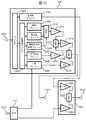
- emergency earthquake
- earthquake information
- digital broadcast
- Prior art date
- Legal status (The legal status is an assumption and is not a legal conclusion. Google has not performed a legal analysis and makes no representation as to the accuracy of the status listed.)
- Ceased
Links
Images





Classifications
-
- H—ELECTRICITY
- H04—ELECTRIC COMMUNICATION TECHNIQUE
- H04N—PICTORIAL COMMUNICATION, e.g. TELEVISION
- H04N21/00—Selective content distribution, e.g. interactive television or video on demand [VOD]
- H04N21/80—Generation or processing of content or additional data by content creator independently of the distribution process; Content per se
- H04N21/81—Monomedia components thereof
- H04N21/8126—Monomedia components thereof involving additional data, e.g. news, sports, stocks, weather forecasts
- H04N21/814—Monomedia components thereof involving additional data, e.g. news, sports, stocks, weather forecasts comprising emergency warnings
-
- H—ELECTRICITY
- H04—ELECTRIC COMMUNICATION TECHNIQUE
- H04H—BROADCAST COMMUNICATION
- H04H20/00—Arrangements for broadcast or for distribution combined with broadcast
- H04H20/53—Arrangements specially adapted for specific applications, e.g. for traffic information or for mobile receivers
- H04H20/59—Arrangements specially adapted for specific applications, e.g. for traffic information or for mobile receivers for emergency or urgency
-
- H—ELECTRICITY
- H04—ELECTRIC COMMUNICATION TECHNIQUE
- H04L—TRANSMISSION OF DIGITAL INFORMATION, e.g. TELEGRAPHIC COMMUNICATION
- H04L12/00—Data switching networks
- H04L12/02—Details
- H04L12/16—Arrangements for providing special services to substations
- H04L12/18—Arrangements for providing special services to substations for broadcast or conference, e.g. multicast
- H04L12/1895—Arrangements for providing special services to substations for broadcast or conference, e.g. multicast for short real-time information, e.g. alarms, notifications, alerts, updates
-
- H—ELECTRICITY
- H04—ELECTRIC COMMUNICATION TECHNIQUE
- H04N—PICTORIAL COMMUNICATION, e.g. TELEVISION
- H04N21/00—Selective content distribution, e.g. interactive television or video on demand [VOD]
- H04N21/40—Client devices specifically adapted for the reception of or interaction with content, e.g. set-top-box [STB]; Operations thereof
- H04N21/47—End-user applications
- H04N21/488—Data services, e.g. news ticker
- H04N21/4882—Data services, e.g. news ticker for displaying messages, e.g. warnings, reminders
Definitions
- the present invention is capable of receiving an earthquake early warning transmitted by digital broadcast, and in particular, a digital broadcast receiving apparatus and a digital broadcast receiving capable of displaying an image and outputting sound with the highest priority on the earthquake early warning. Regarding the method.
- the terrestrial digital broadcasting system in Japan is operated as ISDB-T (Integrated Service Digital Broadcasting) (Terrestrial) system.
- ISDB-T Integrated Service Digital Broadcasting
- TS MPEG-2 transport streams
- IFFT Inverse Fast Fourier Transform
- OFDM Orthogonal Frequency ⁇ ⁇ ⁇ ⁇ Division Multiplexing
- the OFDM transmission signal in the ISDB-T system has a configuration in which 13 OFDM segments obtained by dividing a transmission bandwidth of 6 MHz into 14 parts are connected, and hierarchical transmission of up to three layers is possible in units of OFDM segments. It has become.
- the central segment (segment number # 0) can be set as a partial reception layer assuming reception by a mobile receiver such as a mobile phone.
- a receiver that can receive all 13 segments of the OFDM transmission signal is called a 13-segment receiver, and a receiver that can receive one central segment of the OFDM transmission signal is called a one-segment receiver.
- the OFDM transmission signal in the ISDB-T system is a TMCC (transmission of control information for smoothly performing a demodulation operation of the receiver, such as system identification, transmission parameter switching index, emergency warning broadcast activation flag, transmission parameter of each layer, and the like.
- the frame configuration includes a Transmission (and Multiplexing) Configuration (Control) signal and an AC (Auxiliary Channel) signal that is an extension signal for transmitting additional information related to transmission control of the modulated wave.
- the carrier positions and the number of carriers of TMCC signals and AC signals added as OFDM subcarriers differ depending on transmission parameters.
- emergency warning broadcasting activated by an emergency warning broadcast activation flag transmitted by TMCC is a system that provides emergency information to viewers when a tsunami warning is issued due to the occurrence of an earthquake. It is used to inform more quickly.
- the broadcasting station sets the emergency warning broadcasting activation flag included in the TMCC signal to “1”, and broadcasts with content that can be recognized as emergency warning broadcasting.
- the receiver monitors the emergency warning broadcast activation flag, and if the emergency warning broadcast activation flag is “1”, the viewer is forced to switch the service or shift from the standby state to the normal energized state. It is possible to provide emergency alert broadcasting quickly. (See Patent Document 1)
- the Earthquake Early Warning is a method for immediately estimating the magnitude of an epicenter or earthquake by analyzing initial microtremors (so-called P waves) and main motions (so-called S waves) captured by a seismometer near the epicenter immediately after the occurrence of an earthquake. This is information that estimates the seismic intensity of major motions in each location based on the information and informs it as quickly as possible.
- the Earthquake Early Warning is intended to ensure the safety of the viewer without panicking according to the surrounding situation by notifying the viewer before a strong shake arrives.
- Non-Patent Document 1 As a method for transmitting the earthquake early warning by the ISDB-T method, a system for transmitting the earthquake early warning using an AC signal included in the segment number # 0 has been studied. As an example of using the earthquake early warning system in the ISDB-T system, an alarm clock with an automatic warning function that issues an alarm by receiving an emergency earthquake early warning by a one-segment receiver is disclosed. (See Non-Patent Document 1)
- the non-patent document 1 discloses the necessity of automatically starting a digital broadcast receiver when an earthquake early warning is broadcast.
- Patent Document 1 discloses a reduction in power consumption in a so-called standby state in which emergency alert broadcasting is monitored.
- the present invention has been made in view of such circumstances, and an object of the present invention is to provide an earthquake early warning in a digital broadcast receiving apparatus or a digital broadcast receiving method capable of receiving an earthquake early warning transmitted by digital broadcasting. Priority is given to image display and audio output.
- a digital broadcast receiver for receiving a transmission signal having a digital broadcast signal including a broadcast video signal or a broadcast audio signal and an AC signal for transmitting emergency earthquake information.
- a receiving unit that receives the transmission signal, a first demodulation unit that demodulates and outputs the digital broadcast signal from the transmission signal received by the receiving unit, and a transmission signal that is received by the receiving unit
- a switching unit that switches between the digital broadcast signal output from the first demodulator and the emergency earthquake information signal output from the emergency earthquake information receiver, and the emergency earthquake information receiver
- a control unit that controls the switching unit to select the emergency earthquake information signal when the content of the issued emergency earthquake information indicates that an emergency earthquake warning has been issued. Broadcast receiving apparatuses have been proposed.
- a digital broadcast receiving method for receiving a transmission signal having a digital broadcast signal including a broadcast video signal or a broadcast audio signal and an AC signal for transmitting emergency earthquake information, the transmission A reception step of receiving a signal; a first demodulation step of demodulating and outputting the digital broadcast signal from the transmission signal received in the reception step; and a demodulation of the AC signal from the transmission signal received by the reception unit A second demodulating step, an emergency earthquake information receiving step of receiving the AC signal demodulated in the second demodulating step, detecting the content of emergency earthquake information, and outputting an emergency earthquake information signal, and the emergency earthquake Output from the first demodulation step when the content of the emergency earthquake information detected in the information reception step indicates that the earthquake early warning has been issued
- the digital broadcasting signal, a digital broadcast receiving method having a switching step of switching to the emergency earthquake information signal outputted from the emergency earthquake information receiving step has been proposed to be.
- a digital broadcast receiving apparatus for receiving a transmission signal having a digital broadcast signal including a broadcast video signal or a broadcast audio signal and an AC signal for transmitting emergency earthquake information, the transmission A receiver that receives the signal, a first demodulator that demodulates and outputs the digital broadcast signal from the transmission signal received by the receiver, and a demodulator of the AC signal from the transmission signal that is received by the receiver A second demodulator that receives the AC signal demodulated by the second demodulator, detects the contents of the emergency earthquake information, and outputs an emergency earthquake information signal; and The digital broadcast signal output from the demodulator and the emergency earthquake information signal output from the emergency earthquake information receiver, and the emergency earthquake information detected by the emergency earthquake information receiver When the content of indicates that an earthquake early warning has been issued, a control unit that causes the combining unit to combine so that the ratio of the emergency earthquake information signal is higher than the ratio of the digital broadcast signal, A digital broadcast receiving apparatus provided has been proposed.
- the combining unit includes a first adjustment unit that multiplies the digital broadcast signal by (1 ⁇ ) (0 ⁇ ⁇ 1), and a second unit that multiplies the emergency earthquake information signal by ⁇ . And an adding unit that adds the output of the first adjusting unit and the output of the second adjusting unit, and the control unit is an emergency detected by the emergency earthquake information receiving unit When the content of the earthquake information indicates that an emergency earthquake warning has been issued, it is preferable that ⁇ is greater than 0.5.
- a digital broadcast receiving method for receiving a transmission signal having a digital broadcast signal including a broadcast video signal or a broadcast audio signal and an AC signal for transmitting emergency earthquake information, A reception step of receiving a transmission signal; a first demodulation step of demodulating and outputting the digital broadcast signal from the transmission signal received in the reception step; and the AC signal from the transmission signal received in the reception step.
- the first demodulation step Combining the digital broadcast signal output from the emergency earthquake information signal output from the emergency earthquake information reception step so that the ratio of the emergency earthquake information signal is higher than the ratio of the digital broadcast signal And a digital broadcast receiving method having the steps.
- the synthesizing step includes a first adjustment step for multiplying the digital broadcast signal by (1 ⁇ ) (0 ⁇ ⁇ 1) and a second step for multiplying the emergency earthquake information signal by ⁇ .
- Adjustment step, and an addition step of adding the output of the first adjustment step and the output of the second adjustment step, and the content of the emergency earthquake information detected by the emergency earthquake information receiving unit is an emergency
- ⁇ is greater than 0.5.
- the digital broadcast receiving apparatus or the digital broadcast receiving method capable of receiving the earthquake early warning transmitted by digital broadcasting when the earthquake early warning is broadcast, the emergency earthquake early warning is given priority.
- Image display and audio output are possible.
- Example 1 according to the present invention will be described with reference to FIG.
- FIG. 1 is a block diagram showing a configuration of a digital broadcast receiving apparatus that receives emergency earthquake information transmitted using an AC signal included in segment number # 0 in the ISDB-T system, which is a Japanese terrestrial digital television broadcasting system.
- FIG. 1 is a block diagram showing a configuration of a digital broadcast receiving apparatus that receives emergency earthquake information transmitted using an AC signal included in segment number # 0 in the ISDB-T system, which is a Japanese terrestrial digital television broadcasting system.
- 101 is an antenna
- 102 is a channel selection unit
- 103 is an orthogonal demodulation unit
- 104 is a fast Fourier transform (hereinafter referred to as FFT) unit
- 105 is a demodulation / decoding unit that performs demodulation / decoding operation of the ISDB-T system from the FFT unit 104 to the TS output
- 106 is a descrambling unit
- 107 is a demax unit
- 108 is a compressed broadcast video signal
- 128 and 129 are switching units
- 109 is decoded via the switching unit 128.
- a video display unit 110 displays a broadcast video signal
- 110 is an audio output unit that outputs a broadcast audio signal decoded via the switching unit 129.
- Reference numeral 111 denotes a synchronous reproduction unit
- 112 denotes a frame extraction unit
- 113 denotes a TMCC decoding unit, which performs synchronous signal reproduction for performing the operation of the demodulation decoding unit 105 and obtains information such as transmission parameters.
- the broadcast receiving unit 119 is composed of blocks configured from the channel selection unit 102 to the video display unit 109 and the audio output unit 110.
- 114 is a flag detection unit
- 115 is a data extraction unit
- 116 is a discrimination unit
- 117 is an emergency earthquake early warning output unit.
- the switching units 128 and 129 switch the video signal and the audio signal of the decoding unit 108 and the output unit 117, respectively.
- 118 is a control unit that performs operation control and power control of the broadcast receiving unit 119 and the emergency earthquake information receiving unit 120.
- Control unit 118, broadcast receiving unit 119, and emergency earthquake information receiving unit 120 constitute digital broadcast receiving apparatus 121.
- a channel frequency band to be received by the channel selection unit 102 is extracted from the ISDB-T broadcast received by the antenna 101, converted into a baseband signal by the orthogonal demodulation unit 103, and frequency axis processed by the FFT unit 104.
- the demodulation / decoding unit 105 performs demodulation processing on each carrier on the frequency axis, and performs error correction such as deinterleaving on the frequency axis and time axis, Viterbi decoding, and RS (Reed-Solomon) decoding.
- the ISDB-T signal is demodulated, and a transport stream (hereinafter abbreviated as TS) signal is output to the descrambling unit 106.
- TS transport stream
- the descramble unit 106 scrambles the TS signal that has been scrambled for copyright protection, and outputs the descrambled signal to the demax unit 107.
- a desired compressed broadcast video signal and a compressed digital signal of the broadcast audio signal are extracted and output to the decoding unit 108.
- the decoding unit 108 decodes the compressed broadcast video signal and the compressed broadcast audio signal, the decoded broadcast video signal is transmitted to the video display unit 109 via the switching unit 128, and the decoded broadcast audio signal is switched to the switching unit 129. Is output to the audio output unit 110.
- the synchronous reproduction unit 111 receives the baseband signal from the orthogonal demodulation unit 103, reproduces the symbol synchronous signal, and detects the frequency position of the TMCC signal from the output signal of the FFT unit 104.
- the frame extraction unit 112 demodulates the TMCC signal at the detected frequency position and reproduces the frame synchronization signal.
- the frame synchronization signal is output to the synchronization reproduction unit 111, and phase adjustment with the symbol synchronization signal is performed.
- the TMCC decoding unit 113 performs error correction of the differential cyclic code on the demodulated TMCC signal to obtain TMCC information such as a hierarchical structure and transmission parameters.
- the TMCC information is output to the demodulation / decoding unit 105 and used as information for the demodulation / decoding process.
- the control unit 118 manages operation states of the flag detection unit 114, the data extraction unit 115, the determination unit 116, and the output unit 117 using the control signals 122, 124, 125, and 126, respectively.
- the operating state indicates a state of normal operation (normal), a state of not operating but a state in which it can immediately shift to a normal state (standby), and a state of not operating (stop).
- the control unit 118 limits the power supply amount in the standby state so that power for normal operation is supplied to all locations in the normal state and power is not supplied in the stop state. Or control to limit the power supply location.
- control unit 118 is in a standby state so that the operation unit is stored in a fixed position in the stop state so that the operation unit is normally operated in the normal state for avoiding a failure. Then, control is performed so that the fixed state is released and the machine is in a standby state at the operating position.
- the transmission of emergency earthquake information uses segment No. 0 AC carrier.
- the AC carrier is a transmission path for transmitting additional information for non-broadcasting, but allows emergency earthquake information to be transmitted in addition to the additional information.
- Fig. 2 shows the bit assignment of 204 bits B0 to B203 of the AC signal.
- One bit of B0 is used as a reference for differential demodulation.
- the 3 bits from B1 to B3 are used as configuration identification to distinguish whether it is additional information or emergency earthquake information.
- Additional information or emergency earthquake information is sent with 200 bits B4 to B203.
- emergency earthquake information the same emergency earthquake information is sent on all AC carriers in segment No. 0.
- Fig. 3 shows the standard for differential demodulation.
- the modulation method of the AC carrier is DBPSK, and the amplitude and phase reference for differential demodulation are given by Wi in FIG. This is the same as the current ISDB-T broadcast standard.
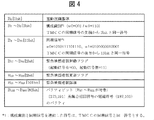
- Fig. 4 shows the bit allocation when emergency earthquake information is transmitted with the AC signal of segment No.0.
- the AC will be used for broadcasters as usual and send additional information.
- ‘001’ and ‘110’ representing the transmission of emergency earthquake information are the same code as the first 3 bits (B1 to B3) of the TMCC synchronization signal, and are sent alternately for each frame at the same timing as the TMCC signal.
- ⁇ 13 bits of B4 to B16 are used as synchronization signals.
- the code obtained by concatenating the configuration identification and the synchronization signal is the same code as the TMCC synchronization signal, and is composed of a 16-bit word.
- the same bits as the TMCC synchronization signals (B1 to B16) are allocated, and the same code as TMCC is transmitted for each frame.
- Fig. 5 shows the meaning of the emergency earthquake warning activation flag.
- Fig. 6 shows the meaning of the Earthquake Early Warning update flag.
- the value of the emergency earthquake warning update flag is incremented by 1 as shown in Fig. 6 and received. Notify the aircraft that the earthquake early warning details have been updated.
- a value of “11” is assumed, and the first value after switching to the emergency earthquake warning activation control is assumed to be “00”.
- the 101 bits of B21 to B121 shall be emergency earthquake warning details.
- Fig. 7 shows the bit assignment of the details of the earthquake early warning.
- Fig. 8 shows the meaning of emergency earthquake warning details by signal identification.
- Fig. 8 The details of emergency earthquake warnings are as shown in Fig. 8 by signal identification, and EEW start signal and EEW test signal are defined.
- the 88 bits from B24 to B111 are the page type, current time, and earthquake details, and the 10 bits from B112 to B121 are CRC-10.
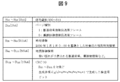
- Fig. 9 shows the details.
- the frame structure for transmitting the EEW activation signal and the EEW test signal is as shown in B24 to B111 in FIG.
- the configuration identifications B1 to B3 and the synchronization signals B4 to B16 are not subject to error correction.
- the information of B17 to B121 is error-correction coded with the shortened code (187,105) of the difference set cyclic code (273,191).
- the parity bits generated by using the shortened code (187,105) of the difference set cyclic code (273,191) are set in the 82 bits of B122 to B203 similarly to the error correction code of TMCC.
- the configuration identification is set to the value shown in FIG.
- the emergency earthquake warning activation flag is set to “with activation signal”, and at the same time, an emergency earthquake warning update flag, emergency earthquake warning details, and a parity bit are set.
- the emergency earthquake warning activation flag is set to “no activation signal” at the end of the earthquake early warning.
- the frame synchronization signal reproduction in the frame extraction unit 112 when the configuration identification portion shown in FIG. 4 is checked and it is confirmed that the emergency earthquake information is sent to the AC, as explained in FIG. Since the code connecting the configuration identification and the synchronization signal is the same as the TMCC synchronization signal, by analog addition of the code identifying the configuration identification and the synchronization signal and the TMCC synchronization signal, It is possible to reproduce a synchronization signal with lower noise than reproduction using only TMCC.
- the 3 bit portion from the beginning of the TMCC synchronization signal and the configuration identification portion shown in FIG. 4 of the AC carrier in the segment No. 0 It is possible to determine that emergency earthquake information has been sent to the AC when all three bits are correlated.
- the channel selection unit 102, the quadrature demodulation unit 103, the FFT unit 104, the synchronous reproduction unit 111, and the frame extraction unit 112 are always in operation, and the segment number 0
- the AC carrier is extracted and demodulated, and the demodulated signal is output from the frame extraction unit 112 to the flag detection unit 114 and the data extraction unit 115.
- the operations of the channel selection unit 102, the quadrature demodulation unit 103, the FFT unit 104, the synchronous reproduction unit 111, and the frame extraction unit 112 need only be performed for segment No. 0, that is, only the one-segment part when receiving emergency earthquake information. .
- the control unit 118 is always operating.
- the flag detection unit 114 and the data extraction unit 115 are operated in a normal state by control signals 122 and 124, respectively.
- the emergency earthquake warning activation flag shown in FIG. 4 is monitored in the sense shown in FIG. 5.
- the initial stage that is, the stage where no emergency earthquake warning is issued
- the activation is started from “no activation signal”.
- the state of switching to “with signal” is monitored.
- the data extraction unit 115 extracts the earthquake early warning activation flag, emergency earthquake early warning update flag, emergency earthquake early warning details, and parity bits shown in FIG. 4, and error correction of the shortened code of the differential cyclic code is performed. Each piece of extracted information is confirmed.
- the discriminating unit 116 and the output unit 117 are stopped by the control signals 125 and 126 in the initial stage, that is, the stage where the emergency earthquake warning is not issued (the emergency earthquake warning activation flag is “no activation signal”), respectively.
- the demodulation / decoding unit 105 the descrambling unit 106, the demax unit 107, the decoding unit 108, the TMCC decoding unit 113, the switching units 128 and 129, and the video display unit 109
- the audio output unit 110 is not operating.
- the flag detection unit 114 changes from “no activation signal” to “with activation signal”.
- the switching state is detected, and the control signal 123 notifies the control unit 118 and the data extraction unit 115 of “the activation signal is present”, that is, the information that the emergency earthquake warning is issued.
- the control unit 118 receives the control signal 123, and sends a signal for causing the determination unit 116 to be in a normal state, the output unit 117 to be in a standby state, and the broadcast receiving unit 119 to be in a standby state by the control signals 125, 126, and 130, respectively.
- the data extraction unit 115 receives the control signal 123, and obtains the earthquake early warning update flag, emergency earthquake early warning details, and parity bit data that have been extracted and confirmed when the emergency earthquake early warning activation flag becomes “with activation signal”. The data is output to the determination unit 116.
- the discriminating unit 116 that is in the normal state by the control signal 125 receives the data from the data extracting unit 115 and performs a CRC check. Then, the signal identification shown in FIG. 7 is confirmed, and the meaning shown in FIG. Determined. Then, a preset process is performed according to each meaning, and if necessary, a control signal 127 and data are sent to the output unit 117.
- the output unit 117 that has been in the standby state by the control signal 126 changes from the standby state to the normal state, and further receives the data from the discriminating unit 116 to generate an emergency earthquake warning. Done.
- the broadcast receiving unit 119 that has been in the standby state by the control signal 130 changes from the standby state to the normal state, and the switching units 128 and 129 are output from the output unit 117.
- the video signal and the audio signal from the output unit 117 are output to the video display unit 109 and the audio output unit 110, respectively, and emergency earthquake warning is performed.
- the broadcast receiving unit 119 is controlled to be in the standby state by the control signal 130. However, only the switching units 128 and 129, the video display unit 109, and the audio output unit 110 are controlled to be in the standby state. Also good.
- the broadcast receiving unit 119 is controlled from the standby state to the normal state by the control signal 127. However, the standby state broadcast receiving unit 119 switches to the switching units 128 and 129, the video display unit 109, and the audio output unit. Only 110 may be controlled to the normal state. Furthermore, the switching units 128 and 129, the video display unit 109, and the audio output unit 110 that are controlled in the standby state may be controlled only in the normal state.
- the standby states of the switching units 128 and 129, the video display unit 109, and the audio output unit 110 are states in which power is supplied so that video display or audio output can be performed quickly when the normal state is reached.
- the discriminating unit 116 When the discriminating unit 116 discriminates that “EEW activation exists in the corresponding area”, the discriminating unit 116 sends the information indicating “the corresponding area exists” to the output unit 117 and sends the control signal 127 for changing from the standby state to the normal state. In response to this, the output unit 117 receives information on “there is a corresponding area”, performs a warning by a buzzer, voice, or the like, or displays a warning by flashing light or displaying the display, and enters a normal state. At the same time, the discriminating unit 116 sends earthquake detailed information and time information such as prefectural information and epicenter information where strong shaking is expected as shown in FIG. 9 to the output unit 117, and the output unit 117 receives the earthquake early warning information.
- the discriminating unit 116 sends earthquake detailed information and time information such as prefectural information and epicenter information where strong shaking is expected as shown in FIG. 9 to the output unit 117, and the output unit 117 receives the earthquake early warning information
- Audio signal output, video signal output, or countdown to the time when an earthquake is expected to occur when receiving the control signal 127 from the determination unit 116, the broadcast receiving unit 119 that has been in the standby state by the control signal 130 changes from the standby state to the normal state, and the switching units 128 and 129 are output from the output unit 117.
- the video signal and the audio signal from the output unit 117 are output to the video display unit 109 and the audio output unit 110, respectively, and emergency earthquake warning is performed.
- the discriminating unit 116 discriminates “EEW activation, no corresponding area”, no control signal or data is output to the output unit 117. However, depending on the case, the same operation as “there is a corresponding area” is performed, and the video display unit 109 displays earthquake detailed information such as prefectural information and epicenter information where strong shaking is expected, or the audio output unit 110. You may make it output by voice.
- the discriminating unit 116 discriminates “EEW test signal applicable area present” or “EEW test signal no applicable area”, this is generally effective when the emergency earthquake information receiving unit 120 is confirmed to operate in the test mode. This is ignored in the normal operation mode, and no control signal or data is output to the output unit 117.
- video information or audio information indicating the test mode is multiplexed in each operation with or without the corresponding area of the EEW activation signal.
- the discriminating unit 116 always needs to confirm the signal identification when the emergency earthquake warning activation flag is “with activation signal”, but at least when the state of the emergency earthquake warning update flag changes, the identification is always confirmed. .
- the flag detection unit 114 monitors the state of switching from “with activation signal” to “without activation signal”, and when the emergency earthquake warning activation flag becomes “without activation signal”, the flag detection unit In 114, a state of switching from “with activation signal” to “without activation signal” is detected, and information about “without activation signal” is transmitted to the control unit 118 and the data extraction unit 115 by the control signal 123.
- the control unit 118 receives the control signal 123, and sends signals for stopping the determination unit 116 and the output unit 117 according to the control signals 125 and 126, respectively. In response to this, the determination unit 116 and the output unit 117 are stopped.
- the control unit 118 sends a control signal 130 to the broadcast receiving unit 119, and the broadcast receiving unit 119 receives this signal, and keeps the broadcast receiving unit 119 in a normal state for a certain period of time, and switches the switching units 128 and 129 to the decoding unit 108 side.
- the decoded broadcast video signal from the ISDB-T broadcast decoding unit 108 received by the channel selection unit 102 at that time is output to the video display unit 109, and the decoded broadcast audio signal is output to the audio output unit 110.
- the broadcast receiving unit 119 is stopped.
- the data extraction unit 115 receives the control signal 123 and stops outputting data to the determination unit 116.
- the stop state of the broadcast receiving unit 119 means that the channel selection unit 102, the orthogonal demodulation unit 103, the FFT unit 104, the synchronous reproduction unit 111, and the frame extraction unit 112 are in one-segment operation, and the demodulation / decoding unit 105, the descrambling unit 106, the demultiplexing unit 107, the decoding unit 108, the TMCC decoding unit 113, the switching units 128 and 129, the video display unit 109, and the audio output unit 110 are not operating.
- the standby state of the broadcast receiving unit 119 means that the channel selection unit 102, the quadrature demodulation unit 103, the FFT unit 104, the synchronous reproduction unit 111, and the frame extraction unit 112 operate in the 13-segment full band, and the demodulation / decoding unit 105, the descrambling unit 106, the demultiplexing unit 107, the decoding unit 108, and the TMCC decoding unit 113 are operating, and the switching units 128 and 129, the video display unit 109, and the audio output unit 110 are not operating.
- the normal state of the broadcast receiving unit 119 is that the channel selection unit 102, the quadrature demodulation unit 103, the FFT unit 104, the synchronous reproduction unit 111, and the frame extraction unit 112 operate in the 13-segment full band, and the demodulation / decoding unit 105, the descrambling unit 106, the demax unit 107, the decoding unit 108, and the TMCC decoding unit 113 are operating, and the switching units 128 and 129, the video display unit 109, and the audio output unit 110 are operating.
- the above description is based on the assumption that the digital broadcast receiving apparatus 121 is not operating. However, the digital broadcast receiving apparatus 121 is operating, that is, the broadcast receiving unit 119 was originally in a normal state. Sometimes, the following operations are performed.
- the flag detection unit 114 detects a state of switching from “without activation signal” to “with activation signal”.
- the data extraction unit 115 is notified of “there is an activation signal”, that is, the information that the emergency earthquake warning is issued.
- the control unit 118 receives the control signal 123, and sends signals for causing the determination unit 116 to be in a normal state and the output unit 117 to be in a standby state by the control signals 125 and 126, respectively.
- control unit 118 sends a control signal 130 to the broadcast receiving unit 119, and the broadcast receiving unit 119 receives the control signal 130, and outputs to the switching units 128 and 129 from the decoded broadcast video signal from the decoding unit 108 to the output unit 117.
- the data extraction unit 115 receives the control signal 123, and obtains the earthquake early warning update flag, emergency earthquake early warning details, and parity bit data that have been extracted and confirmed when the emergency earthquake early warning activation flag becomes “with activation signal”. The data is output to the determination unit 116.
- the discriminating unit 116 that is in the normal state by the control signal 125 receives the data from the data extracting unit 115 and performs a CRC check. Then, the signal identification shown in FIG. 7 is confirmed, and the meaning shown in FIG. Determined. Then, a preset process is performed according to each meaning, and if necessary, a control signal 127 and data are sent to the output unit 117.
- the output unit 117 that has been in the standby state by the control signal 126 changes from the standby state to the normal state, and further receives the data from the discriminating unit 116 to generate an emergency earthquake warning. Done.
- the broadcast reception unit 119 receives the video from the output unit 117 from the decoded broadcast video signal from the decoding unit 108 for each of the switching units 128 and 129. The signal is switched from the decoded broadcast audio signal from the decoding unit 108 to the audio signal from the output unit 117. Then, the earthquake early warning is performed by the video display unit 109 and the audio output unit 110 by the video signal and the audio signal from the output unit 117, respectively.
- the flag detection unit 114 monitors the state of switching from “with activation signal” to “without activation signal”, and when the emergency earthquake warning activation flag becomes “without activation signal”, the flag detection unit 114 A state of switching from “with activation signal” to “without activation signal” is detected, and information about “without activation signal” is transmitted to the control unit 118 and the data extraction unit 115 by the control signal 123.
- the control unit 118 receives the control signal 123, and sends signals for stopping the determination unit 116 and the output unit 117 according to the control signals 125 and 126, respectively. In response to this, the determination unit 116 and the output unit 117 are stopped.
- control unit 118 sends a control signal 130 to the broadcast receiving unit 119, and the broadcast receiving unit 119 receives the signal, and the video signal from the output unit 117 is decoded from the decoding unit 108 to each of the switching units 128 and 129.
- the broadcast video signal is switched from the audio signal from the output unit 117 to the decoded broadcast audio signal from the decoding unit 108.
- the data extraction unit 115 receives the control signal 123 and stops outputting data to the determination unit 116.
- the switching units 128 and 129 are switched from the broadcast video signal or broadcast audio signal of the normal television broadcast to the video signal or audio signal of the emergency earthquake early warning, Emergency earthquake alerts can be displayed with priority and image output. Further, since it is only necessary to have one video display unit and one audio output unit, it is possible to reduce the price with a simple configuration. Furthermore, when the digital broadcast receiving apparatus 121 is not operating, the broadcast receiving unit 119 can be automatically activated, and when the digital broadcast receiving apparatus 121 is operating, it can be quickly switched to the emergency earthquake warning.
- the output unit 117 is not changed from the stop state to the normal state only by the emergency earthquake warning start flag being set to “with start signal”, and is further set to the normal state when the signal identification is “EEW start, corresponding area exists”. Therefore, in the case of “EEW activation, no applicable area”, or from “There is an activation signal” until “EEW activation, with applicable area” is determined, the power consumption can be reduced, and the emergency earthquake warning activation flag When “Start signal is present” is set to the standby state from the stop state, when the signal identification is “EEW start, corresponding area is present”, the normal state can be quickly obtained and the emergency earthquake warning can be output promptly.
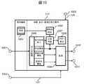
- 1001 is a data input unit from the determination unit 116
- 1002 is an input unit of the control signal 127 from the determination unit 116
- 1003 is an input unit of the control signal 126 from the control unit 118
- 1004 is a clock unit
- 1005 is a current time setting.
- 1006 is a data storage unit
- 1007 is a comparison determination unit
- 1008 is a buzzer generation unit
- 1009 is a processing unit
- 1010 is a video signal output unit
- 1011 is an audio signal output unit.
- the clock unit 1004 always operates even when the output unit 117 is stopped, and indicates an accurate time.
- GPS Global Positioning System
- use of a radio clock function that automatically corrects errors by receiving standard radio waves use of a function that automatically updates the correct time from the outside, such as the Internet, etc.
- the current time setting unit 1005, the data storage unit 1006, the comparison determination unit 1007, the buzzer generation unit 1008, and the processing unit 1009 operate when the output unit 117 is in the “standby state” and the “energized state” and is in the “stop state”. Does not work.
- the output unit 117 When the output unit 117 receives the control signal 126 from the control unit 118 via the input unit 1003 and enters a standby state, the current time setting unit 1005 always extracts and sets the current time from the clock unit 1004.
- the discriminating unit 116 discriminates that “EEW activation exists in the corresponding area”, the discriminating unit 116 sends the information “existing area exists” via the input unit 1001 of the output unit 117 and a strong shaking shown in FIG. 9 is expected.
- Detailed earthquake information such as prefecture information and epicenter information and time information are sent to the output unit 117.
- the output unit 117 receives this and stores it in the data storage unit 1006 at the same time, and the time information is stored and simultaneously compared with the current time of the current time setting unit 1005 by the comparison determination unit 1007.
- the sent time information in the data storage unit 1006 is the current time information of the broadcasting station when the broadcasting station transmits, and has a predetermined accuracy.
- the comparison determination unit 1007 uses this as a threshold value and the threshold value is determined by the comparison determination unit 1007. If it is within the value, it is determined as “normal”, and if it exceeds the threshold value, it is determined as “abnormal”.
- the comparison determination unit 1007 controls the buzzer generation unit 1008 to generate a buzzer when it is determined that “the area is present” and “normal”.
- RF capture broadcast waves when emergency earthquake warnings have been issued in the past
- Has time information at the time of RF capture so that the current time of the current time setting unit 1005 exceeds the threshold value and the comparison determination unit 1007 is determined to be “abnormal” and does not generate a buzzer.
- a malfunction that a buzzer is generated by the buzzer generation unit 1008 can be prevented.
- a warning generated by voice or the like or a warning display by flashing light may be used.
- the processing unit 1009 stores time information, earthquake detailed information such as prefecture information and epicenter information in the data storage unit 1006, and simultaneously prepares output from the video signal output unit 1010 and outputs from the audio signal output unit 1011. Make preparations. For example, although not shown in FIG. 10, the time to reach the earthquake is calculated from the installation location of the digital broadcast receiving apparatus stored in advance and the detailed earthquake information.
- the video signal output unit 1010 and the audio signal output unit 1011 output an output signal only in the “normal state”.
- the discriminating unit 116 discriminates that “EEW activation exists in the corresponding area”
- the discriminating unit 116 provides information on “the corresponding area exists” via the input unit 1001 of the output unit 117, and prefectural information in which strong shaking shown in FIG. Earthquake detailed information such as earthquake location information and time information are sent to the output unit 117, and a control signal 127 for changing from the standby state to the normal state is sent via the input unit 1002.
- the output unit 117 receives the control signal 127 and enters a normal state.
- the video signal output unit 1010 and the audio signal output unit 1011 receive the signal from the processing unit 1009 and perform the video signal output and the audio signal output of the emergency earthquake warning, respectively.
- the contents to be output are detailed earthquake information and time information such as prefectural information and epicenter information where strong shaking is expected as shown in FIG. 9, or countdown information until the time when the earthquake is expected to occur.
- the output unit 117 receives the control signal 126 in the stopped state from the control unit 118 via the input unit 1003 and enters the stopped state. That is, except for the clock unit 1004, all blocks stop operating.
- the buzzer since the buzzer is generated in the standby state, the buzzer can quickly notify the occurrence of the earthquake, and the power consumption can be reduced because the video signal output and the audio signal output are operated only in the normal state.
- Example 2 according to the present invention will be described with reference to FIGS.
- FIG. 11 is a block diagram showing a configuration of a digital broadcast receiving apparatus that receives emergency earthquake information transmitted using an AC signal included in segment number # 0 in the ISDB-T system, which is a Japanese terrestrial digital television broadcasting system.
- FIG. 11 is a block diagram showing a configuration of a digital broadcast receiving apparatus that receives emergency earthquake information transmitted using an AC signal included in segment number # 0 in the ISDB-T system, which is a Japanese terrestrial digital television broadcasting system.
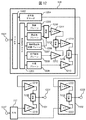
- 1101 and 1102 are synthesis units, and their details are shown in FIG.
- FIG. 1 The difference between FIG. 1 and FIG. 11 is that the switching units 128 and 129 are replaced by combining units 1101 and 1102, respectively.
- FIG. 12 also shows the decoding unit 108 in detail.
- 1201 is a desired compressed broadcast video signal and compressed broadcast audio signal input unit output from the demax unit 107; 1202 is a filter unit that distributes the compressed broadcast video signal and the compressed broadcast audio signal; 1203 Is a video decoding unit that decodes a compressed broadcast video signal for each of a moving image, a still image, a character graphic, and a subtitle, and 1204 is an audio decoding unit that performs a decoding process for the compressed broadcast audio signal, 1205 is a moving image plane unit for displaying a moving image, 1206 is a still image plane unit for displaying a still image, 1207 is a moving image still image switching plane unit indicating information for switching a moving image and a still image for each pixel, Reference numeral 1208 denotes a character graphic plane part for displaying a character graphic, 1209 denotes a subtitle plane part for displaying a subtitle, and 1210.
- 1215 is an adjustment unit that adjusts the synthesis ratio of the output signal of the caption plane unit 1209
- 1216 is an addition unit that synthesizes the output signals of the adjustment units 1214 and 1215.
- the decoding unit 108 is configured as described above. .
- a broadcast video signal is output from the adder 1216, and a broadcast audio signal is output from the audio decoding unit 1204.
- 1218 is an adjustment unit that adjusts the composite ratio of the broadcast video signal that is the output signal of the adder 1216
- 1219 is an adjustment unit that adjusts the composite ratio of the video signal of the emergency earthquake warning that is the output signal of the output unit 117
- 1220 is the adjustment
- An adder for combining the output signals of the units 1218 and 1219, 1221 is an output unit of a synthesized video signal that is an output signal of the adder 1220, and constitutes the combiner 1101.
- the synthesizing unit 1102 is configured as described above.
- the switching unit 1210 switches the moving image from the moving image plane unit 1205 and the still image from the still image plane unit 1206 for each pixel based on the information of the moving image still image switching plane unit 1207.
- the output signal of the switching unit 1210 is adjusted by the adjusting unit 1211 to a synthesis ratio “1 ⁇ 1” times.
- the character graphic that is an output signal from the character graphic plane unit 1208 is adjusted by the adjustment unit 1212 to the composition ratio “ ⁇ 1” times.
- ⁇ 1 represents opacity and takes a value from 0 to 1.
- the adder 1213 combines the output signals of the adjusters 1211 and 1212. When ⁇ 1 is 0, only the output signal of the switching unit 1210 is obtained, and when ⁇ 1 is 1, only the character graphic that is the output signal from the character / graphic plane unit 1208 is obtained.
- the output signal of the addition unit 1213 is adjusted by the adjustment unit 1214 to be “1 ⁇ 2” times the composition ratio.
- the subtitle which is an output signal from the subtitle plane unit 1209 is adjusted by the adjustment unit 1215 to the synthesis ratio “ ⁇ 2” times.
- ⁇ 2 represents opacity and takes a value from 0 to 1.
- the adder 1216 combines the output signals from the adjusters 1214 and 1215. When ⁇ 2 is 0, only the output signal of the adder 1213 is provided, and when ⁇ 2 is 1, only the caption that is the output signal from the caption plane unit 1209 is provided.
- subtitles, character figures, still images, and moving images are synthesized, and a broadcast video signal is output from the adder 1216.
- the broadcast video signal from the adding unit 1216 is adjusted by the adjusting unit 1218 to the synthesis ratio “1 ⁇ 3” times.
- the video signal of the earthquake early warning that is the output signal from the output unit 117 is adjusted by the adjustment unit 1219 to the composition ratio “ ⁇ 3” times.
- the output signals of the adjustment units 1218 and 1219 are combined by the addition unit 1220, and the output signal of the addition unit 1220 is output to the output unit 1221 as a synthesized video signal.
- ⁇ 3 represents opacity and takes a value from 0 to 1.
- the combined video signal output from the output unit 1221 is only the broadcast video signal from the adder 1218.
- the combined video signal output from the output unit 1221 is only the video signal of the emergency earthquake warning that is the output signal from the output unit 117.
- the broadcast audio signal from the audio system decoding unit 1204 is adjusted by the adjusting unit 1222 to the synthesis ratio “1 ⁇ 4” times.
- the emergency earthquake warning audio signal which is an output signal from the output unit 117
- the output signals of the adjusting units 1222 and 1223 are combined by the adding unit 1224, and the output signal of the adding unit 1224 is output to the output unit 1225 as a synthesized voice signal.
- ⁇ 4 represents a synthesis rate and takes a value from 0 to 1.
- the synthesized audio signal output from the output unit 1225 is only the broadcast audio signal from the audio system decoding unit 1204.
- ⁇ 4 1, the synthesized speech signal output from the output unit 1225 is only the emergency earthquake warning speech signal that is the output signal from the output unit 117.
- the video signal and audio signal of the emergency earthquake warning can be made more conspicuous than the broadcast video signal and broadcast audio signal, respectively.
- Example 3 according to the present invention will be described with reference to FIG.
- the synthesizing unit 1101 of FIG. 12 is omitted, and the video signal of the earthquake early warning is directly written in the caption plane unit 1209 of the decoding unit.
- the subtitle plane unit 1209 updates the video signal of the earthquake early warning from the output unit 117 with the subtitle decoded from the video system decoding unit 1203.
- the subtitle plane unit 1209 does not write the decoded subtitle from the video system decoding unit 1203 in the place where the video signal of the emergency earthquake warning from the output unit 117 is written.
- ⁇ 2 is set to a value larger than 0.5.
- an emergency earthquake warning video signal can be displayed while avoiding the display portion. It is also possible to display not only caption but also a video signal of an emergency earthquake warning while avoiding a display portion where the broadcaster emphasizes or makes the video display emphasized in data broadcasting or the like. Furthermore, when the receiver displays an important video by itself, the video signal of the earthquake early warning can be displayed by avoiding the display portion.
- FFT Fast Fourier transform
- Digital broadcast receiving device 128, 129 ... Switching unit, 1001, 1002, 1003 ... Input unit, 1004 ... Clock unit, 1005 ... Current time Setting unit, 1006 ... Data storage unit, 1007 ... Comparison judgment unit, 1008 ... Buzzer generation unit, 1009 ... Processing unit, 1010 ... Video signal Power unit, 1011 ... Audio signal output unit, 1101, 1102 ... Synthesis unit, 1201 ... Input unit, 1202 ... Filter unit, 1203 ... Video system decoding unit, 1204 ... Audio system decoding unit, 1205 ... Video plane unit, 1206 ... Stationary Picture plane part, 1207 ... Moving picture still picture switching plane part, 1208 ... Character graphic plane part, 1209 ...
- Subtitle plane part for displaying subtitles 1210 ... Switching part, 1211, 1212, 1214, 1215 ... Adjusting part, 1213, 1216 ... Adding unit, 1217 ... Data input unit, 1218, 1219 ... Adjusting unit, 1220 ... Adding unit, 1221 ... Output unit, 1222, 1223 ... Adjusting unit, 1224 ... Adding unit, 1225 ... Output unit.
Landscapes
- Engineering & Computer Science (AREA)
- Signal Processing (AREA)
- Business, Economics & Management (AREA)
- Emergency Management (AREA)
- Multimedia (AREA)
- Computer Networks & Wireless Communication (AREA)
- Two-Way Televisions, Distribution Of Moving Picture Or The Like (AREA)
- Circuits Of Receivers In General (AREA)
Abstract
デジタル放送で伝送される緊急地震速報を受信可能なデジタル放送受信装置または方法において、緊急地震速報を優先して画像表示、音声出力すること。 緊急地震速報が放送されたときは、切替部128、129により、通常のテレビ放送の放送映像信号や放送音声信号から緊急地震速報の映像信号や音声信号に切替える。これにより、緊急地震速報を最優先または最上位で画像表示、音声出力するデジタル放送受信装置を提供することができる。
Description
本発明は、デジタル放送によって伝送される緊急地震速報を受信することが可能であって、特に、緊急地震速報を最優先で画像表示、音声出力することが可能なデジタル放送受信装置およびデジタル放送受信方法に関する。
日本における地上デジタル放送方式はISDB-T(Integrated Service Digital Broadcasting -Terrestrial)方式として運用されている。このISDB-T方式では、複数のMPEG-2トランスポートストリーム(MPEG-2 Transport Stream、以下、TSとする)を再多重により一つのTSとし、伝送路符号化処理を施した後、IFFT(Inverse Fast Fourier Transform)により複数のサブキャリアからなるOFDM(Orthogonal Frequency Division Multiplexing)送信信号に一括して変換し、放送波として送信する。
ここで、ISDB-T方式におけるOFDM送信信号は、伝送帯域幅6MHzを14等分したOFDMセグメントを13個連結した構成となっており、OFDMセグメントを単位として最大3階層までの階層伝送が可能となっている。また、OFDM送信信号の13セグメントの内、中央のセグメント(セグメント番号#0)は、携帯電話などの移動受信機での受信を想定した部分受信階層として設定できる。なお、OFDM送信信号の13セグメント全てを受信可能な受信機を13セグメント受信機、OFDM送信信号の中央の1セグメントを受信可能な受信機をワンセグメント受信機と呼ぶ。
ISDB-T方式におけるOFDM送信信号は、システム識別、伝送パラメータ切替指標、緊急警報放送用起動フラグ、各階層の伝送パラメータなど、受信機の復調動作を円滑に行なうための制御情報を伝送するTMCC(Transmission and Multiplexing Configuration Control)信号と、変調波の伝送制御に関する付加情報を伝送するための拡張用信号であるAC(Auxiliary Channel)信号が付加されたフレーム構成となっている。このフレーム構成において、OFDMサブキャリアとして付加されるTMCC信号とAC信号のキャリア位置及びキャリア本数は、伝送パラメータによって異なる。
ここで、TMCCによって伝送される緊急警報放送用起動フラグにより起動される緊急警報放送(EWS:Emergency Warning System)とは、地震発生による津波警報などが発令された場合に、視聴者に緊急情報をより早く知らせるために利用されているものである。ISDB-T方式において緊急警報放送を運用する場合、放送局がTMCC信号に含まれる緊急警報放送用起動フラグを「1」として、緊急警報放送と認識できるコンテンツで放送を実施する。受信機は緊急警報放送用起動フラグを監視して、緊急警報放送用起動フラグが「1」となれば、強制的なサービスの切り替えや、待機状態から通常の通電状態への移行により、視聴者に素早く緊急警報放送を提供することを可能としている。(特許文献1を参照)
更に高度化された緊急情報を伝送するシステムとして、気象庁が発表する緊急地震速報(EEW:Earthquake Early Warning)がある。緊急地震速報とは、地震の発生直後に、震源に近い地震計でとらえた初期微動(いわゆるP波)と主要動(いわゆるS波)を解析して震源や地震の規模を直ちに推定し、これに基づいて各地での主要動の震度を推定し、可能な限り素早く知らせる情報である。また、緊急地震速報では、強い揺れが到着する前に知らせることで、視聴者に対して周囲の状況に応じて慌てずに身の安全を確保することを目的としている。この緊急地震速報をISDB-T方式で伝送する場合の方法について、セグメント番号#0に含まれるAC信号を用いて緊急地震速報を伝送するシステムが検討されている。このISDB-T方式における緊急地震速報システムを使用した一例として、ワンセグメント受信機により緊急地震速報を受信して警報を発する自動警告機能付き目覚まし時計が公開されている。(非特許文献1を参照)
「緊急放送による受信端末の自動起動」平成20年度技研公開 展示資料 NHK放送技術研究所編 平成20年5月20日発行
上記非特許文献1では、緊急地震速報が放送されたときにデジタル放送受信機が自動的に起動することの必要性が開示されている。
また、上記特許文献1では、緊急警報放送を監視しているいわゆるスタンバイ状態での低消費電力化について開示されている。
しかしながら、いずれの文献にも、緊急地震速報を出力する場合の画像表示や音声出力の受信機動作については開示されていない。
本発明はこのような状況に鑑みてなされたものであり、その目的は、デジタル放送によって伝送される緊急地震速報を受信することが可能なデジタル放送受信装置またはデジタル放送受信方法において、緊急地震速報を優先して画像表示、音声出力することにある。
上記目的を達成するために、本発明によれば、放送映像信号あるいは放送音声信号を含むデジタル放送信号と、緊急地震情報を伝送するためのAC信号とを有する伝送信号を受信するデジタル放送受信装置であって、前記伝送信号を受信する受信部と、前記受信部で受信された伝送信号から前記デジタル放送信号を復調し、出力する第1の復調部と、前記受信部で受信された伝送信号から前記AC信号を復調する第2の復調部と、前記第2の復調部で復調されたAC信号を受信し、緊急地震情報の内容を検出し、緊急地震情報信号を出力する緊急地震情報受信部と、前記第1の復調部から出力される前記デジタル放送信号と、前記緊急地震情報受信部から出力される前記緊急地震情報信号とを切替える切替部と、前記緊急地震情報受信部で検出された緊急地震情報の内容が、緊急地震速報が発報されたことを示している場合に、前記切替部が前記緊急地震情報信号を選択するように制御する制御部と、を備えたデジタル放送受信装置が提案されている。
また、本発明によれば、放送映像信号あるいは放送音声信号を含むデジタル放送信号と、緊急地震情報を伝送するためのAC信号とを有する伝送信号を受信するデジタル放送受信方法であって、前記伝送信号を受信する受信ステップと、前記受信ステップで受信された伝送信号から前記デジタル放送信号を復調し、出力する第1の復調ステップと、前記受信部で受信された伝送信号から前記AC信号を復調する第2の復調ステップと、前記第2の復調ステップで復調されたAC信号を受信し、緊急地震情報の内容を検出し、緊急地震情報信号を出力する緊急地震情報受信ステップと、前記緊急地震情報受信ステップで検出された緊急地震情報の内容が、緊急地震速報が発報されたことを示している場合に、前記第1の復調ステップから出力される前記デジタル放送信号を、前記緊急地震情報受信ステップから出力される前記緊急地震情報信号に切替える切替ステップと、を有するデジタル放送受信方法が提案されている。
更に、本発明によれば、放送映像信号あるいは放送音声信号を含むデジタル放送信号と、緊急地震情報を伝送するためのAC信号とを有する伝送信号を受信するデジタル放送受信装置であって、前記伝送信号を受信する受信部と、前記受信部で受信された伝送信号から前記デジタル放送信号を復調し、出力する第1の復調部と、前記受信部で受信された伝送信号から前記AC信号を復調する第2の復調部と、前記第2の復調部で復調されたAC信号を受信し、緊急地震情報の内容を検出し、緊急地震情報信号を出力する緊急地震情報受信部と、前記第1の復調部から出力される前記デジタル放送信号と、前記緊急地震情報受信部から出力される前記緊急地震情報信号とを合成する合成部と、前記緊急地震情報受信部で検出された緊急地震情報の内容が、緊急地震速報が発報されたことを示している場合に、前記合成部が前記デジタル放送信号の比率より前記緊急地震情報信号の比率が高くなるように合成させる制御部と、を備えたデジタル放送受信装置が提案されている。更に、本発明では、前記合成部は、前記デジタル放送信号を(1-α)倍(0<α<1)にする第1の調整部と、前記緊急地震情報信号をα倍にする第2の調整部と、前記第1の調整部の出力と前記第2の調整部の出力を加算する加算部とで構成され、かつ、前記制御部は、前記緊急地震情報受信部で検出された緊急地震情報の内容が、緊急地震速報が発報されたことを示している場合に、前記αを0.5より大きくすることが好ましい。
加えて、本発明によれば、放送映像信号あるいは放送音声信号を含むデジタル放送信号と、緊急地震情報を伝送するためのAC信号とを有する伝送信号を受信するデジタル放送受信方法であって、前記伝送信号を受信する受信ステップと、前記受信ステップで受信された伝送信号から前記デジタル放送信号を復調し、出力する第1の復調ステップと、前記受信ステップで受信された伝送信号から前記AC信号を復調する第2の復調ステップと、前記第2の復調ステップで復調されたAC信号を受信し、緊急地震情報の内容を検出し、緊急地震情報信号を出力する緊急地震情報受信ステップと、前記緊急地震情報受信ステップで検出された緊急地震情報の内容が、緊急地震速報が発報されたことを示している場合に、前記第1の復調ステップから出力される前記デジタル放送信号と、前記緊急地震情報受信ステップから出力される前記緊急地震情報信号とを、前記デジタル放送信号の比率より前記緊急地震情報信号の比率が高くなるように合成する合成ステップと、を有するデジタル放送受信方法が提案されている。なお、本発明では、前記合成ステップは、前記デジタル放送信号を(1-α)倍(0<α<1)にする第1の調整ステップと、前記緊急地震情報信号をα倍にする第2の調整ステップと、前記第1の調整ステップの出力と前記第2の調整ステップの出力を加算する加算ステップとを有し、前記緊急地震情報受信部で検出された緊急地震情報の内容が、緊急地震速報が発報されたことを示している場合に、前記αが0.5より大きくなることが好ましい。
本発明によれば、デジタル放送によって伝送される緊急地震速報を受信することが可能なデジタル放送受信装置またはデジタル放送受信方法において、緊急地震速報が放送されたときに、緊急地震速報を優先して画像表示、音声出力することができる。
以下、本発明を実施するための形態について図面を参照して詳述する。なお、図面において、同一符号は、同一または相当部分を示す。
本発明に係る実施例1について、図1を用いて説明する。
図1は、日本の地上デジタルテレビジョン放送方式であるISDB-T方式において、セグメント番号#0に含まれるAC信号を用いて伝送された緊急地震情報を受信するデジタル放送受信装置の構成を示すブロック図である。
101はアンテナ、102は選局部、103は直交復調部、104は高速フーリエ変換(以下、FFT)部、105はFFT部104からTS出力までのISDB-T方式の復調・復号動作を行う復調復号部、106はデスクランブル部、107はデマックス部、108は圧縮された放送映像信号、圧縮された放送音声信号のデコード部、128、129は切替部、109は切替部128を介してデコードされた放送映像信号の表示を行う映像表示部、110は切替部129を介してデコードされた放送音声信号の出力を行う音声出力部であり、これらが放送映像信号、放送音声信号を再生する主要ブロックである。また、111は同期再生部、112はフレーム抽出部、113はTMCC復号部であり、復調復号部105の動作を行うための同期信号再生や、伝送パラメータなどの情報入手を行う。選局部102から映像表示部109及び音声出力部110までで構成されるブロックで放送受信部119が構成される。
一方、114はフラグ検出部、115はデータ抽出部、116は判別部、117は緊急地震速報の出力部であり、これらで緊急地震情報受信部120が構成される。
切替部128、129は、それぞれデコード部108と出力部117の映像信号、音声信号の切替えを行なう。
118は制御部であり、放送受信部119や緊急地震情報受信部120の動作制御や電力制御を行う。
制御部118、放送受信部119、緊急地震情報受信部120でデジタル放送受信装置121が構成される。
以下、詳細に動作を説明する。アンテナ101で受信されたISDB-T放送から選局部102で受信すべきチャネル周波数帯域が抽出され、直交復調部103でベースバンド信号とされ、FFT部104で周波数軸処理がなされる。これを受け、復調復号部105では周波数軸上の各キャリアに対して復調処理が行われ、周波数軸及び時間軸のデインターリーブ、ビタビ復号やRS(リード・ソロモン)復号などの誤り訂正が施されてISDB-T信号が復調され、トランスポートストリーム(以下、TSと略す)信号がデスクランブル部106に出力される。デスクランブル部106では著作権保護のためにスクランブルのかけられているTS信号のスクランブルが解除されデマックス部107に出力される。デマックス部107では希望の圧縮された放送映像信号及び圧縮された放送音声信号のデジタル信号が抽出されデコード部108に出力される。デコード部108では圧縮された放送映像信号や圧縮された放送音声信号が復号され、復号された放送映像信号は切替部128を介して映像表示部109に、復号された放送音声信号は切替部129を介して音声出力部110に出力される。
一方、同期再生部111では直交復調部103からのベースバンド信号を受け、シンボル同期信号が再生されるとともにFFT部104の出力信号からTMCC信号の周波数位置が検出される。フレーム抽出部112では検出された周波数位置のTMCC信号が復調されるとともにフレーム同期信号が再生される。フレーム同期信号は同期再生部111に出力され、シンボル同期信号との位相調整が行われる。TMCC復号部113では復調されたTMCC信号に差集合巡回符号の誤り訂正が施され、階層構造、伝送パラメータなどTMCC情報が得られる。このTMCC情報は復調復号部105に出力され、復調復号処理のための情報として利用される。
次に本発明の主要部分である制御部118、緊急地震情報受信部120の動作を説明する。制御部118は、制御信号122、124、125、126を用い、それぞれフラグ検出部114、データ抽出部115、判別部116、出力部117の動作状態を管理する。動作状態とは、正常に動作している状態(通常)、動作していないがすぐに通常状態に移行可能な状態(スタンバイ)、動作していない状態(停止)を表す。制御部118は、消費電力低減のために、通常状態では普通に動作させるための電力を全箇所に供給するように、停止状態では電力供給をしないように、スタンバイ状態では電力供給量を制限したり、または、電力供給箇所を制限したりするように制御する。また、制御部118は、故障回避のためなどに、通常状態では普通に稼働している状態になるように、停止状態では稼働部が固定位置に格納されている状態になるように、スタンバイ状態では固定を解除して稼働位置で待機している状態になるように制御する。
図2から図9を用い、緊急地震情報受信部120で受信する緊急地震情報の構成を説明する。
緊急地震情報の伝送はセグメントNo.0のACキャリアを用いる。ACキャリアは非放送用の付加情報を伝送するための伝送路であるが、付加情報以外に緊急地震情報も伝送できるようにする。
図2はAC信号の204ビットB0~B203のビット割当てを示したものである。B0の1ビットは差動復調の基準とする。B1~B3の3ビットは構成識別とし、付加情報であるか、緊急地震情報であるか区別する。B4~B203の200ビットによって、付加情報または緊急地震情報を送出する。なお、緊急地震情報を送出する際は、セグメントNo.0内の全てのACキャリアで同一の緊急地震情報を送出する。
図3は差動復調の基準を示したものである。ACキャリアの変調方式はDBPSKとし、差動復調の振幅及び位相基準は図3のWiで与えられる。これは現在のISDB-T放送の標準規格と同じである。
図4は緊急地震情報をセグメントNo.0のAC信号で伝送する場合のビット割当てを示したものである。
構成識別を000,010,011,100,101,111とした場合は、ACは従来通り、放送事業者向けの利用とし、付加情報を送出する。
構成識別を001,110とした場合は、緊急地震情報を送出する。
緊急地震情報の伝送を表す‘001’と‘110’は、TMCCの同期信号の先頭3ビット(B1~B3)と同一の符号とし、TMCC信号と同一のタイミングでフレームごとに交互に送出する。
B4~B16の13ビットは同期信号とする。緊急地震情報の場合、構成識別と同期信号を連結した符号は、TMCCの同期信号と同一符号とし、16ビットのワードで構成する。同期信号はw0=0011010111101110とそれをビット反転したw1=1100101000010001の2種類とする。TMCC同期信号(B1~B16)と同じビットを割当て、フレーム毎にTMCCと同じ符号を送出する。
B17~B18の2ビットは緊急地震速報起動フラグとする。
図5は緊急地震速報起動フラグの意味を示したものである。
緊急地震速報が発報されたときに、受信機を自動起動し、かつ、AC信号で緊急地震速報を送出していることを示すため、緊急地震速報起動フラグとして2ビットを割り当てる。
AC信号は、伝送される情報が無い場合、全てのビットが‘1’で変調されるため、緊急地震速報起動制御ありの状態を‘00’とする。また、起動フラグの信頼性を向上するため、緊急地震速報起動フラグに2ビットを使用して符号間距離が最大となる反転信号とする。また、起動フラグの信頼性を確保するために‘10’、‘01’は使用しない。
B19~B20の2ビットは緊急地震速報更新フラグとする。
図6は緊急地震速報更新フラグの意味を示したものである。
緊急地震速報起動制御ありの状態が継続中に緊急地震速報詳細(B21~B121)の内容が更新された場合は、図6に示すように緊急地震速報更新フラグの値を1ずつインクリメントし、受信機に緊急地震速報詳細が更新されたことを通知する。緊急地震速報起動制御なしの場合は‘11’の値を取るものとし、緊急地震速報起動制御ありに切り替わった最初の値を‘00’とする。
B21~B121の101ビットは緊急地震速報詳細とする。
図7は緊急地震速報詳細のビット割り当てを示す。
B21~B23の3ビットは信号識別とし、緊急地震速報やその試験信号などを区別する。
図8は信号識別による緊急地震速報詳細の意味を示す。
信号識別によって緊急地震速報詳細は図8に示す意味とし、EEW起動信号とEEW試験信号を定義する。
B24~B111の88ビットは、ページ種別、現在時刻、地震詳細情報とし、B112~B121の10ビットは、CRC-10とする。
図9に、その詳細を示す。
EEW起動信号及びEEW試験信号を伝送するフレーム構造は図9のB24~B111に示す通りとする。
B112~B121の10ビットは情報の信頼性をチェックするためのCRC-10とする。
緊急地震情報は重要な情報であり、高い信頼性が要求されることから、TMCCと同様に差集合巡回符号を用いた誤り訂正符号で保護する。構成識別B1~B3及び同期信号B4~B16は誤り訂正の対象外とする。B17~B121の情報は、差集合巡回符号(273,191)の短縮符号(187,105)で誤り訂正符号化する。B122~B203の82ビットには、TMCCの誤り訂正符号と同様に、差集合巡回符号(273,191)の短縮符号(187,105)を用い生成されたパリティビットを設定する。
以上、図2から図9で説明した緊急地震情報の使用方法を図4を用い簡単に説明する。
緊急地震情報をセグメントNo.0のACキャリアで伝送している場合は構成識別を図4に示す値に設定する。地震が起こり緊急地震速報を発報するときには、緊急地震速報起動フラグを"起動信号有り"とし、同時に緊急地震速報更新フラグ、緊急地震速報詳細、パリティビットを設定する。緊急地震速報終了時に緊急地震速報起動フラグを"起動信号なし"とする。
図2から図9で説明した緊急地震情報を受信する動作を図1を用い説明する。
図1のフレーム抽出部112において、セグメントNo.0内のACキャリアが抽出復調されるとともに図4で示した構成識別で緊急地震情報の送出が確認され、更に同期が確立される。このとき、セグメントNo.0内の全てのACキャリアで同一の緊急地震情報が送出されているため、セグメントNo.0内のACキャリア全てをアナログ加算することで、低雑音化でも緊急地震情報の復調が可能になる。例えばN本のACキャリアがあったとすれば緊急地震情報の振幅がN倍になるのに対して雑音はそれぞれのACキャリアにおいて無相関であるためN倍にならない(電力でいえば、緊急地震情報はNの2乗倍に対し雑音はN倍にしかならない)。
また、フレーム抽出部112でのフレーム同期信号再生において、図4で示した構成識別部分を調べてACに緊急地震情報が送出されていることの確認ができたときには、図4で説明したように、構成識別と同期信号を連結した符号はTMCCの同期信号と同一となっているので、構成識別と同期信号を連結した符号とTMCCの同期信号とをアナログ加算することで、上記した理由により、TMCCだけで再生するよりも低雑音化での同期信号を再生することができる。
さらにまた、フレーム抽出部112において図4で示した構成識別部分を調べる方法として、TMCCの同期信号の先頭から3ビット部分と、セグメントNo.0内のACキャリアの図4で示した構成識別部分の相関をとることにより、3ビット全てに相関がある場合にACに緊急地震情報が送出されていると判断することが可能である。
緊急地震情報受信部120で緊急地震情報を受信しようとしているときには、選局部102、直交復調部103、FFT部104、同期再生部111、フレーム抽出部112は常に動作しており、セグメントNo.0内のACキャリアが抽出復調され、その復調信号がフレーム抽出部112からフラグ検出部114とデータ抽出部115に出力される。選局部102、直交復調部103、FFT部104、同期再生部111、フレーム抽出部112の動作は緊急地震情報を受信しようとしているときにはセグメントNo.0、すなわちワンセグ部分のみの処理を行うのみでよい。これにより、ISDB-T放送の13セグメント全帯域を処理するよりも低消費電力動作とすることができる。
また、緊急地震情報受信部120で緊急地震情報を受信しようとしているときには、制御部118は常に動作している。
フラグ検出部114とデータ抽出部115は、それぞれ制御信号122、124により通常状態で動作している。フラグ検出部114では、図4に示す緊急地震速報起動フラグが図5に示す意味で監視されており、初期段階、すなわち緊急地震速報が発報されていない段階では"起動信号なし"から"起動信号有り"と切替わる状態が監視されている。これと同時にデータ抽出部115では、図4に示す緊急地震速報起動フラグ、緊急地震速報更新フラグ、緊急地震速報詳細、パリティビットが抽出され、差集合巡回符号の短縮符号の誤り訂正が行われ、抽出した各情報が確定される。
判別部116、出力部117は、初期段階、すなわち緊急地震速報が発報されていない段階(緊急地震速報起動フラグが"起動信号なし")では、それぞれ制御信号125、126により停止状態にある。
初期段階、すなわち緊急地震速報が発報されていない段階では、復調復号部105、デスクランブル部106、デマックス部107、デコード部108、TMCC復号部113と、切替部128、129、映像表示部109、音声出力部110は動作していない状態となっている。
地震が起こり緊急地震速報が発報されたとき、すなわち、緊急地震速報起動フラグが"起動信号有り"となった場合には、フラグ検出部114では"起動信号なし"から"起動信号有り"と切替わる状態が検出され、制御信号123により制御部118とデータ抽出部115に"起動信号有り"、すなわち緊急地震速報が発報された情報が伝えられる。制御部118は制御信号123を受け、制御信号125、126、130により、それぞれ判別部116を通常状態に、出力部117をスタンバイ状態に、放送受信部119をスタンバイ状態にさせる信号を送る。一方、データ抽出部115は制御信号123を受け、緊急地震速報起動フラグが"起動信号有り"となった時点での抽出確定された緊急地震速報更新フラグ、緊急地震速報詳細、パリティビットのデータを判別部116に出力する。
制御信号125により通常状態となった判別部116では、データ抽出部115からのデータを受けCRCチェックを行った後、図7に示す信号識別が確認され、図8に示すどの意味であるかが判別される。そして、それぞれの意味に応じ、あらかじめ設定された処理が行われ、必要であれば制御信号127とデータが出力部117へ送られる。
制御信号126によりスタンバイ状態となっていた出力部117では、判別部116からの制御信号127を受けた場合には、スタンバイ状態から通常状態となり、さらに判別部116からのデータを受け緊急地震速報が行われる。同時に制御信号130によりスタンバイ状態となっていた放送受信部119では、判別部116からの制御信号127を受けた場合には、スタンバイ状態から通常状態となり、また、切替部128、129は出力部117からの信号を選択するように制御され、出力部117からの映像信号、音声信号はそれぞれ映像表示部109、音声出力部110に出力され、緊急地震速報が行われる。
なお、上記では制御信号130により放送受信部119がスタンバイ状態に制御される例を示したが、切替部128、129、映像表示部109、音声出力部110のみをスタンバイ状態に制御するようにしてもよい。また、上記では制御信号127により放送受信部119がスタンバイ状態から通常状態に制御される例を示したが、スタンバイ状態の放送受信部119から切替部128、129、映像表示部109、音声出力部110のみを通常状態に制御するようにしてもよい。さらに、スタンバイ状態に制御された切替部128、129、映像表示部109、音声出力部110を通常状態に制御するだけにしてもよい。これらにより、放送受信部119を制御するよりも低消費電力で緊急地震速報を行なうことができる。ここで、切替部128、129、映像表示部109、音声出力部110のスタンバイ状態とは、通常状態になったときにすばやく映像表示または音声出力できるように通電しておく状態をいう。
判別部116と出力部117の詳細な動作を図8を用いて説明する。
判別部116が"EEW起動 該当地域有り"を判別した場合、判別部116は出力部117に"該当地域有り"の情報を送るとともにスタンバイ状態から通常状態とする制御信号127を送る。出力部117はこれを受け、"該当地域有り"の情報を受けブザーや音声などによる警告または光の点滅やディスプレイ表示による警告表示を行うとともに、通常状態となる。同時に、判別部116は、図9に示す強い揺れが予想される都道府県情報や震源地情報などの地震詳細情報や時刻情報を出力部117に送り、出力部117はこれを受け、緊急地震速報の音声信号出力、映像信号出力、または地震が発生すると思われる時間までのカウントダウンを行う。同時に制御信号130によりスタンバイ状態となっていた放送受信部119では、判別部116からの制御信号127を受けた場合には、スタンバイ状態から通常状態となり、また、切替部128、129は出力部117からの信号を選択するように制御され、出力部117からの映像信号、音声信号はそれぞれ映像表示部109、音声出力部110に出力され、緊急地震速報が行われる。
判別部116が"EEW起動 該当地域なし"を判別した場合、出力部117への制御信号やデータ出力は行わない。ただし、場合によっては、"該当地域有り"と同様の動作をさせ、映像表示部109に強い揺れが予想される都道府県情報や震源地情報などの地震詳細情報を表示させる、または音声出力部110で音声出力させてもよい。
判別部116が"EEW試験信号 該当地域有り"または"EEW試験信号 該当地域なし"を判別した場合、これは一般的に緊急地震情報受信部120を試験モードで動作確認しているときに有効となるものであり、普通の動作モードでは無視され、出力部117への制御信号やデータ出力は行わない。試験モードのときは、例えば、EEW起動信号の該当地域有り、または、該当地域なしのそれぞれの動作に、テストモードであることを示す映像情報または音声情報を多重する。
判別部116は信号識別の確認を緊急地震速報起動フラグが"起動信号有り"の場合常時行う必要があるが、少なくとも緊急地震速報更新フラグの状態が変化した場合には必ず信号識別の確認を行う。
次に、フラグ検出部114では"起動信号有り"から"起動信号なし"と切替わる状態が監視されており、緊急地震速報起動フラグが"起動信号なし"となった場合には、フラグ検出部114では"起動信号有り"から"起動信号なし"と切替わる状態が検出され、制御信号123により制御部118とデータ抽出部115に"起動信号なし"の情報が伝えられる。制御部118は制御信号123を受け、制御信号125、126により、それぞれ判別部116、出力部117を停止状態とさせる信号を送る。判別部116、出力部117はこれを受け、停止状態となる。同時に制御部118は制御信号130を放送受信部119に送り、放送受信部119はこれを受け、一定時間のみ放送受信部119を通常状態に保ち、また、切替部128、129をデコード部108側に切替え、そのとき選局部102で受信しているISDB-T放送のデコード部108からの復号された放送映像信号を映像表示部109に、復号された放送音声信号を音声出力部110に出力し、一定時間経過後、放送受信部119を停止状態とする。一方、データ抽出部115は制御信号123を受け、判別部116へのデータ出力を停止する。
ここで、放送受信部119の停止状態とは、選局部102、直交復調部103、FFT部104、同期再生部111、フレーム抽出部112がワンセグ動作しており、復調復号部105、デスクランブル部106、デマックス部107、デコード部108、TMCC復号部113と、切替部128、129、映像表示部109、音声出力部110が動作していない状態をいう。
放送受信部119のスタンバイ状態とは、選局部102、直交復調部103、FFT部104、同期再生部111、フレーム抽出部112が13セグメント全帯域動作しており、復調復号部105、デスクランブル部106、デマックス部107、デコード部108、TMCC復号部113が動作しており、切替部128、129、映像表示部109、音声出力部110が動作していない状態をいう。
放送受信部119の通常状態とは、選局部102、直交復調部103、FFT部104、同期再生部111、フレーム抽出部112が13セグメント全帯域動作しており、復調復号部105、デスクランブル部106、デマックス部107、デコード部108、TMCC復号部113が動作しており、切替部128、129、映像表示部109、音声出力部110が動作している状態をいう。
以上の説明は、デジタル放送受信装置121が動作していない状態のときを前提に説明したが、デジタル放送受信装置121が動作している状態、すなわち、放送受信部119がもともと通常状態であったときには、以下の動作とする。
緊急地震速報起動フラグが"起動信号有り"となった場合には、フラグ検出部114では"起動信号なし"から"起動信号有り"と切替わる状態が検出され、制御信号123により制御部118とデータ抽出部115に"起動信号有り"、すなわち緊急地震速報が発報された情報が伝えられる。制御部118は制御信号123を受け、制御信号125、126により、それぞれ判別部116を通常状態に、出力部117をスタンバイ状態にさせる信号を送る。同時に制御部118は制御信号130を放送受信部119に送り、放送受信部119はこれを受け、切替部128、129それぞれに対して、デコード部108からの復号された放送映像信号から出力部117からの映像信号へ、デコード部108からの復号された放送音声信号から出力部117からの音声信号へ、切替える準備を行う。一方、データ抽出部115は制御信号123を受け、緊急地震速報起動フラグが"起動信号有り"となった時点での抽出確定された緊急地震速報更新フラグ、緊急地震速報詳細、パリティビットのデータを判別部116に出力する。
制御信号125により通常状態となった判別部116では、データ抽出部115からのデータを受けCRCチェックを行った後、図7に示す信号識別が確認され、図8に示すどの意味であるかが判別される。そして、それぞれの意味に応じ、あらかじめ設定された処理が行われ、必要であれば制御信号127とデータが出力部117へ送られる。
制御信号126によりスタンバイ状態となっていた出力部117では、判別部116からの制御信号127を受けた場合には、スタンバイ状態から通常状態となり、さらに判別部116からのデータを受け緊急地震速報が行われる。同時に放送受信部119では、判別部116からの制御信号127を受けた場合には、切替部128、129それぞれに対して、デコード部108からの復号された放送映像信号から出力部117からの映像信号へ、デコード部108からの復号された放送音声信号から出力部117からの音声信号への切り替えが行われる。そして、出力部117からの映像信号、音声信号により、それぞれ映像表示部109、音声出力部110で緊急地震速報が行われる。
フラグ検出部114では"起動信号有り"から"起動信号なし"と切替わる状態が監視されており、緊急地震速報起動フラグが"起動信号なし"となった場合には、フラグ検出部114では"起動信号有り"から"起動信号なし"と切替わる状態が検出され、制御信号123により制御部118とデータ抽出部115に"起動信号なし"の情報が伝えられる。制御部118は制御信号123を受け、制御信号125、126により、それぞれ判別部116、出力部117を停止状態とさせる信号を送る。判別部116、出力部117はこれを受け、停止状態となる。同時に制御部118は制御信号130を放送受信部119に送り、放送受信部119はこれを受け、切替部128、129それぞれに対して、出力部117からの映像信号からデコード部108からの復号された放送映像信号へ、出力部117からの音声信号からデコード部108からの復号された放送音声信号へ、切り替えが行われる。一方、データ抽出部115は制御信号123を受け、判別部116へのデータ出力を停止する。
本実施形態によれば、緊急地震速報が放送されたときは、切替部128、129により、通常のテレビ放送の放送映像信号や放送音声信号から緊急地震速報の映像信号や音声信号に切替えるため、緊急地震速報を最優先で画像表示、音声出力することができる。また、映像表示部と音声出力部をそれぞれ1系統持つだけで良いため、簡単な構成で低価格とすることができる。さらに、デジタル放送受信装置121が動作していない状態のときは放送受信部119を自動起動でき、デジタル放送受信装置121が動作していた状態のときは緊急地震速報に速やかに切替えが行える。
また、緊急地震速報起動フラグが"起動信号有り"となるだけで出力部117を停止状態から通常状態にするのではなく、さらに信号識別が"EEW起動 該当地域有り"のときに通常状態とするので、"EEW起動 該当地域なし"の場合や、"起動信号有り"から"EEW起動 該当地域有り"が判別されるまでの間は低消費電力とすることができ、且つ、緊急地震速報起動フラグが"起動信号有り"で停止状態からスタンバイ状態とすることで、信号識別が"EEW起動 該当地域有り"のときに高速に通常状態とし、速やかに緊急地震速報を出力することができる。
以下、本発明の主要ブロックである出力部117の一実施例を図10を用いて説明する。
1001は判別部116からのデータの入力部、1002は判別部116からの制御信号127の入力部、1003は制御部118からの制御信号126の入力部、1004は時計部、1005は現時刻設定部、1006はデータ記憶部、1007は比較判断部、1008はブザー発生部、1009は処理部、1010は映像信号出力部、1011は音声信号出力部である。
時計部1004は出力部117が停止状態でも常時動作しており、正確な時刻を示している。正確な時刻とする方法としてGPS(Global Positioning System)の利用、標準電波を受信して誤差を自動修正する電波時計機能の利用、インターネットなど外部から正確な時刻を自動更新する機能の利用が考えられ、これらに限るものではないが、ISDB-T放送から時刻情報を得ることは後に述べる理由により好ましくない。
現時刻設定部1005、データ記憶部1006、比較判断部1007、ブザー発生部1008、処理部1009は、出力部117が"スタンバイ状態"と"通電状態"のときに動作し"停止状態"のときは動作しない。
出力部117が制御部118からの制御信号126を入力部1003を介して受けスタンバイ状態となったときに、現時刻設定部1005は時計部1004から現在時刻を常時抽出し設定する。判別部116が"EEW起動 該当地域有り"を判別した場合、判別部116は出力部117の入力部1001を介し"該当地域有り"の情報を送るとともに、図9に示す強い揺れが予想される都道府県情報や震源地情報などの地震詳細情報や時刻情報を出力部117に送る。出力部117ではこれを受けると同時にデータ記憶部1006に記憶し、時刻情報は記憶されると同時に比較判断部1007で現時刻設定部1005の現在時刻と比較される。送られてきたデータ記憶部1006内の時刻情報は放送局側が送信したときの放送局の現在時刻情報であり、定められた精度をもっている。これに放送局側の処理遅延、放送電波が受信機までに届く伝搬遅延、これを受信するデジタル放送受信装置121の処理遅延と、時計部1004の精度を加味した時間、最大でもこれらを全て加算した時間の正負(進み遅れ)以上には、データ記憶部1006内の時刻情報と現時刻設定部1005の現在時刻はずれることがないため、これをスレッシュホールド値として、比較判断部1007は、スレッシュホールド値内である場合には、"正常"と判断し、スレッシュホールド値を超える場合には、"異常"と判断する。比較判断部1007は"該当地域有り"且つ"正常"と判断したときにブザー発生部1008を制御しブザーを発生させる。これにより、過去に緊急地震速報が発報されたときの放送波を蓄積しておき(以下、RFキャプチャと示す)これを再送信されたような攻撃を受けた場合においても、RFキャプチャした信号はRFキャプチャした時点の時刻情報を持っているため、現時刻設定部1005の現在時刻とはスレッシュホールド値を超える状態となり比較判断部1007では"異常"と判断されブザーを発生しない動作をとり、ブザー発生部1008でブザーを発生させるという誤作動を防ぐことができる。なお、ブザー発生部1008の代わりに音声などによる警告発生または光の点滅による警告表示でもよい。
処理部1009は、データ記憶部1006に時刻情報、都道府県情報や震源地情報などの地震詳細情報が記憶されると同時に、映像信号出力部1010からの出力準備、音声信号出力部1011からの出力準備を行う。例えば、図10では図示していないが、あらかじめ記憶してあるデジタル放送受信装置の設置場所と地震詳細情報から地震到達までの時間を計算しておくことなどを行う。
映像信号出力部1010、音声信号出力部1011からは"通常状態"のときにのみ出力信号が出力される。
判別部116が"EEW起動 該当地域有り"を判別した場合、判別部116は出力部117の入力部1001を介し"該当地域有り"の情報、図9に示す強い揺れが予想される都道府県情報や震源地情報などの地震詳細情報や時刻情報を出力部117に送るとともに、入力部1002を介しスタンバイ状態から通常状態とする制御信号127を送る。出力部117では制御信号127を受け通常状態となる。
通常状態となり、映像信号出力部1010、音声信号出力部1011は、処理部1009からの信号を受け、それぞれ緊急地震速報の映像信号出力、音声信号出力を行う。出力する内容は、図9に示す強い揺れが予想される都道府県情報や震源地情報などの地震詳細情報や時刻情報、または、地震が発生すると思われる時間までのカウントダウン情報などである。
出力部117は、制御部118からの停止状態の制御信号126を入力部1003を介して受け、停止状態となる。すなわち、時計部1004を除き、全てのブロックが動作を停止する。
図10の実施例によれば、時刻情報と現在時刻の比較を行うことにより、警告発生の誤作動を防ぐことができる。
さらに、ブザー発生をスタンバイ状態で行っているためブザーにより地震発生をいち早く知らせることができるとともに、映像信号出力と音声信号出力を通常状態でのみの動作としているため消費電力を低減できる。
本発明に係る実施例2について、図11および図12を用いて説明する。
図11は、日本の地上デジタルテレビジョン放送方式であるISDB-T方式において、セグメント番号#0に含まれるAC信号を用いて伝送された緊急地震情報を受信するデジタル放送受信装置の構成を示すブロック図である。
1101、1102は合成部であり、図12にその詳細を示している。
図1と図11との違いは、切替部128、129をそれぞれ合成部1101、1102にしたことである。
以下、図12を用いて合成部1101、1102の説明を行なう。図12ではデコード部108も詳細に示している。
1201はデマックス部107から出力された希望の圧縮された放送映像信号及び圧縮された放送音声信号の入力部、1202は圧縮された放送映像信号と圧縮された放送音声信号とを振り分けるフィルタ部、1203は圧縮された放送映像信号を動画、静止画、文字図形、字幕それぞれに対して復号処理を行なう映像系デコード部、1204は圧縮された放送音声信号に対して復号処理を行なう音声系デコード部、1205は動画表示をするための動画プレーン部、1206は静止画表示をするための静止画プレーン部、1207は動画と静止画を画素ごとに切替えるための情報を示した動画静止画切替プレーン部、1208は文字図形を表示するための文字図形プレーン部、1209は字幕を表示するための字幕プレーン部、1210は動画静止画切替プレーン部1207の情報により動画プレーン部1205からの動画と静止画プレーン部1206からの静止画の切替えを画素ごとに行なう切替部、1211は切替部1210の出力信号の合成比率を調整する調整部、1212は文字図形プレーン部1208の出力信号の合成比率を調整する調整部、1213は調整部1211、1212の出力信号を合成する加算部、1214は加算部1213の出力信号の合成比率を調整する調整部、1215は字幕プレーン部1209の出力信号の合成比率を調整する調整部、1216は調整部1214、1215の出力信号を合成する加算部であり、以上でデコード部108を構成する。加算部1216からは放送映像信号が、音声系デコード部1204からは放送音声信号が出力される。
1217は判別部116からのデータ入力部である。
1218は加算部1216の出力信号である放送映像信号の合成比率を調整する調整部、1219は出力部117の出力信号である緊急地震速報の映像信号の合成比率を調整する調整部、1220は調整部1218、1219の出力信号を合成する加算部、1221は加算部1220の出力信号である合成映像信号の出力部であり、以上で合成部1101を構成する。
1222は音声系デコード部1204の出力信号である放送音声信号の合成比率を調整する調整部、1223は出力部117の出力信号である緊急地震速報の音声信号の合成比率を調整する調整部、1224は調整部1222、1223の出力信号を合成する加算部、1225は加算部1224の出力信号である合成音声信号の出力部であり、以上で合成部1102を構成する。
デコード部108の放送映像信号の合成方法を説明する。
切替部1210では、動画静止画切替プレーン部1207の情報により、動画プレーン部1205からの動画と静止画プレーン部1206からの静止画を画素ごとに切替える。切替部1210の出力信号は調整部1211で合成比率を"1-α1"倍に調整される。一方、文字図形プレーン部1208からの出力信号である文字図形は調整部1212で合成比率を"α1"倍に調整される。ここで、α1は不透明度を表し、0から1までの値をとる。加算部1213では調整部1211、1212の出力信号を合成する。α1が0の場合は切替部1210の出力信号のみとなり、α1が1の場合は文字図形プレーン部1208からの出力信号である文字図形のみとなる。
加算部1213の出力信号は調整部1214で合成比率を"1-α2"倍に調整される。一方、字幕プレーン部1209からの出力信号である字幕は調整部1215で合成比率を"α2"倍に調整される。ここで、α2は不透明度を表し、0から1までの値をとる。加算部1216では調整部1214、1215の出力信号を合成する。α2が0の場合は加算部1213の出力信号のみとなり、α2が1の場合は字幕プレーン部1209からの出力信号である字幕のみとなる。
以上のように、字幕、文字図形、静止画、動画は合成され、加算部1216から放送映像信号が出力される。
合成部1101では、加算部1216からの放送映像信号が調整部1218で合成比率"1-α3"倍に調整される。一方、出力部117からの出力信号である緊急地震速報の映像信号が調整部1219で合成比率"α3"倍に調整される。そして、調整部1218、1219の出力信号が加算部1220で合成され、加算部1220の出力信号が合成映像信号として出力部1221に出力される。ここで、α3は不透明度を表し、0から1までの値をとる。α3が0の場合は出力部1221から出力される合成映像信号は加算部1218からの放送映像信号のみとなる。α3が1の場合は出力部1221から出力される合成映像信号は出力部117からの出力信号である緊急地震速報の映像信号のみとなる。
合成部1102では、音声系デコード部1204からの放送音声信号が調整部1222で合成比率"1-α4"倍に調整される。一方、出力部117からの出力信号である緊急地震速報の音声信号が調整部1223で合成比率"α4"倍に調整される。そして、調整部1222、1223の出力信号が加算部1224で合成され、加算部1224の出力信号が合成音声信号として出力部1225に出力される。ここで、α4は合成率を表し、0から1までの値をとる。α4が0の場合は出力部1225から出力される合成音声信号は音声系デコード部1204からの放送音声信号のみとなる。α4が1の場合は出力部1225から出力される合成音声信号は出力部117からの出力信号である緊急地震速報の音声信号のみとなる。
本実施例ではα3、α4を0.5より大きい値とすることで、緊急地震速報の映像信号や音声信号を、それぞれ、放送映像信号や放送音声信号よりも目立つようにすることができる。
本発明に係る実施例3について、図13を用いて説明する。
図13では、図12の合成部1101を省略し、デコード部108の字幕プレーン部1209に直接緊急地震速報の映像信号を書き込む。字幕プレーン部1209は映像系デコード部1203からのデコードされた字幕を出力部117からの緊急地震速報の映像信号を更新する。または、字幕プレーン部1209は出力部117からの緊急地震速報の映像信号が書き込まれた場所には映像系デコード部1203からのデコードされた字幕を書き込まない。また、α2を0.5より大きい値とする。
さらに、字幕プレーン部1209に字幕が表示されていた場合、その表示部分を避けて緊急地震速報の映像信号を表示することもできる。なお、字幕だけではなく、データ放送などで放送事業者が映像表示を強調または必須としている表示部分を避けて緊急地震速報の映像信号を表示することもできる。さらに、受信機が自ら重要な映像表示をしている場合は、その表示部分を避けて緊急地震速報の映像信号を表示することもできる。
以上により、映像系の合成部を増やすことなく緊急地震速報の映像信号を放送映像信号よりも目立つように合成することができる。
101…アンテナ、102…選局部、103…直交復調部、104…高速フーリエ変換(FFT)部、105…復調復号部、106…デスクランブル部、107…デマックス部、108…デコード部、109…映像表示部、110…音声出力部、111…同期再生部、112…フレーム抽出部、113…TMCC復号部、114…フラグ検出部、115…データ抽出部、116…判別部、117…出力部、118…制御部、119…放送受信部、120…緊急地震情報受信部、121…デジタル放送受信装置、128、129…切替部、1001、1002、1003…入力部、1004…時計部、1005…現時刻設定部、1006…データ記憶部、1007…比較判断部、1008…ブザー発生部、1009…処理部、1010…映像信号出力部、1011…音声信号出力部、1101、1102…合成部、1201…入力部、1202…フィルタ部、1203…映像系デコード部、1204…音声系デコード部、1205…動画プレーン部、1206…静止画プレーン部、1207…動画静止画切替プレーン部、1208…文字図形プレーン部、1209…字幕を表示するための字幕プレーン部、1210…切替部、1211、1212、1214、1215…調整部、1213、1216…加算部、1217…データ入力部、1218、1219…調整部、1220…加算部、1221…出力部、1222、1223…調整部、1224…加算部、1225…出力部。
Claims (6)
- 放送映像信号あるいは放送音声信号を含むデジタル放送信号と、緊急地震情報を伝送するためのAC信号とを有する伝送信号を受信するデジタル放送受信装置であって、
前記伝送信号を受信する受信部と、
前記受信部で受信された伝送信号から前記デジタル放送信号を復調し、出力する第1の復調部と、
前記受信部で受信された伝送信号から前記AC信号を復調する第2の復調部と、
前記第2の復調部で復調されたAC信号を受信し、緊急地震情報の内容を検出し、緊急地震情報信号を出力する緊急地震情報受信部と、
前記第1の復調部から出力される前記デジタル放送信号と、前記緊急地震情報受信部から出力される前記緊急地震情報信号とを切替える切替部と、
前記緊急地震情報受信部で検出された緊急地震情報の内容が、緊急地震速報が発報されたことを示している場合に、前記切替部が前記緊急地震情報信号を選択するように制御する制御部と、
を備えることを特徴とするデジタル放送受信装置。 - 放送映像信号あるいは放送音声信号を含むデジタル放送信号と、緊急地震情報を伝送するためのAC信号とを有する伝送信号を受信するデジタル放送受信方法であって、
前記伝送信号を受信する受信ステップと、
前記受信ステップで受信された伝送信号から前記デジタル放送信号を復調し、出力する第1の復調ステップと、
前記受信ステップで受信された伝送信号から前記AC信号を復調する第2の復調ステップと、
前記第2の復調ステップで復調されたAC信号を受信し、緊急地震情報の内容を検出し、緊急地震情報信号を出力する緊急地震情報受信ステップと、
前記緊急地震情報受信ステップで検出された緊急地震情報の内容が、緊急地震速報が発報されたことを示している場合に、前記第1の復調ステップから出力される前記デジタル放送信号を、前記緊急地震情報受信ステップから出力される前記緊急地震情報信号に切替える切替ステップと、
を有することを特徴とするデジタル放送受信方法。 - 放送映像信号あるいは放送音声信号を含むデジタル放送信号と、緊急地震情報を伝送するためのAC信号とを有する伝送信号を受信するデジタル放送受信装置であって、
前記伝送信号を受信する受信部と、
前記受信部で受信された伝送信号から前記デジタル放送信号を復調し、出力する第1の復調部と、
前記受信部で受信された伝送信号から前記AC信号を復調する第2の復調部と、
前記第2の復調部で復調されたAC信号を受信し、緊急地震情報の内容を検出し、緊急地震情報信号を出力する緊急地震情報受信部と、
前記第1の復調部から出力される前記デジタル放送信号と、前記緊急地震情報受信部から出力される前記緊急地震情報信号とを合成する合成部と、
前記緊急地震情報受信部で検出された緊急地震情報の内容が、緊急地震速報が発報されたことを示している場合に、前記合成部が前記デジタル放送信号の比率より前記緊急地震情報信号の比率が高くなるように合成させる制御部と、
を備えることを特徴とするデジタル放送受信装置。 - 前記合成部は、
前記デジタル放送信号を(1-α)倍(0<α<1)にする第1の調整部と、
前記緊急地震情報信号をα倍にする第2の調整部と、
前記第1の調整部の出力と前記第2の調整部の出力を加算する加算部とで構成され、
前記制御部は、前記緊急地震情報受信部で検出された緊急地震情報の内容が、緊急地震速報が発報されたことを示している場合に、前記αを0.5より大きくすることを特徴とする請求項3に記載のデジタル放送受信装置。 - 放送映像信号あるいは放送音声信号を含むデジタル放送信号と、緊急地震情報を伝送するためのAC信号とを有する伝送信号を受信するデジタル放送受信方法であって、
前記伝送信号を受信する受信ステップと、
前記受信ステップで受信された伝送信号から前記デジタル放送信号を復調し、出力する第1の復調ステップと、
前記受信ステップで受信された伝送信号から前記AC信号を復調する第2の復調ステップと、
前記第2の復調ステップで復調されたAC信号を受信し、緊急地震情報の内容を検出し、緊急地震情報信号を出力する緊急地震情報受信ステップと、
前記緊急地震情報受信ステップで検出された緊急地震情報の内容が、緊急地震速報が発報されたことを示している場合に、前記第1の復調ステップから出力される前記デジタル放送信号と、前記緊急地震情報受信ステップから出力される前記緊急地震情報信号とを、前記デジタル放送信号の比率より前記緊急地震情報信号の比率が高くなるように合成する合成ステップと、
を有することを特徴とするデジタル放送受信方法。 - 前記合成ステップは、
前記デジタル放送信号を(1-α)倍(0<α<1)にする第1の調整ステップと、
前記緊急地震情報信号をα倍にする第2の調整ステップと、
前記第1の調整ステップの出力と前記第2の調整ステップの出力を加算する加算ステップとを有し、
前記緊急地震情報受信部で検出された緊急地震情報の内容が、緊急地震速報が発報されたことを示している場合に、前記αが0.5より大きくなることを特徴とする請求項5に記載のデジタル放送受信方法。
Applications Claiming Priority (4)
| Application Number | Priority Date | Filing Date | Title |
|---|---|---|---|
| JP2010080100A JP2011216926A (ja) | 2010-03-31 | 2010-03-31 | デジタル放送受信装置およびデジタル放送受信方法 |
| JP2010-080101 | 2010-03-31 | ||
| JP2010080101A JP2011216927A (ja) | 2010-03-31 | 2010-03-31 | デジタル放送受信装置およびデジタル放送受信方法 |
| JP2010-080100 | 2010-03-31 |
Publications (1)
| Publication Number | Publication Date |
|---|---|
| WO2011121813A1 true WO2011121813A1 (ja) | 2011-10-06 |
Family
ID=44711592
Family Applications (1)
| Application Number | Title | Priority Date | Filing Date |
|---|---|---|---|
| PCT/JP2010/064620 Ceased WO2011121813A1 (ja) | 2010-03-31 | 2010-08-27 | デジタル放送受信装置およびデジタル放送受信方法 |
Country Status (1)
| Country | Link |
|---|---|
| WO (1) | WO2011121813A1 (ja) |
Cited By (1)
| Publication number | Priority date | Publication date | Assignee | Title |
|---|---|---|---|---|
| CN112712673A (zh) * | 2020-12-21 | 2021-04-27 | 北京数码视讯科技股份有限公司 | 地震预警方法和系统 |
Citations (3)
| Publication number | Priority date | Publication date | Assignee | Title |
|---|---|---|---|---|
| JP2004336411A (ja) * | 2003-05-08 | 2004-11-25 | Canon Inc | 放送受信装置及び放送受信方式 |
| JP2009302993A (ja) * | 2008-06-16 | 2009-12-24 | Nec Electronics Corp | 緊急情報報知システム、catv受信機、及び緊急情報報知方法 |
| JP2010045830A (ja) * | 2006-02-07 | 2010-02-25 | Toshiba Corp | デジタル放送システムとこのシステムに用いられる放送装置及び受信機 |
-
2010
- 2010-08-27 WO PCT/JP2010/064620 patent/WO2011121813A1/ja not_active Ceased
Patent Citations (3)
| Publication number | Priority date | Publication date | Assignee | Title |
|---|---|---|---|---|
| JP2004336411A (ja) * | 2003-05-08 | 2004-11-25 | Canon Inc | 放送受信装置及び放送受信方式 |
| JP2010045830A (ja) * | 2006-02-07 | 2010-02-25 | Toshiba Corp | デジタル放送システムとこのシステムに用いられる放送装置及び受信機 |
| JP2009302993A (ja) * | 2008-06-16 | 2009-12-24 | Nec Electronics Corp | 緊急情報報知システム、catv受信機、及び緊急情報報知方法 |
Cited By (1)
| Publication number | Priority date | Publication date | Assignee | Title |
|---|---|---|---|---|
| CN112712673A (zh) * | 2020-12-21 | 2021-04-27 | 北京数码视讯科技股份有限公司 | 地震预警方法和系统 |
Similar Documents
| Publication | Publication Date | Title |
|---|---|---|
| WO2011142160A1 (ja) | デジタル放送受信装置およびデジタル放送受信方法 | |
| JP2009273040A (ja) | 放送配信装置、放送受信機、放送システム、放送配信方法、放送受信方法、および放送制御方法 | |
| JP5801561B2 (ja) | デジタル放送送信装置およびデジタル放送送信方法 | |
| JP2011114593A (ja) | デジタル放送受信装置 | |
| JP5478353B2 (ja) | デジタル放送受信装置およびデジタル放送受信方法 | |
| JP2011216926A (ja) | デジタル放送受信装置およびデジタル放送受信方法 | |
| JP2009302993A (ja) | 緊急情報報知システム、catv受信機、及び緊急情報報知方法 | |
| JP2012015930A (ja) | デジタル放送受信装置およびデジタル放送受信方法 | |
| WO2011121813A1 (ja) | デジタル放送受信装置およびデジタル放送受信方法 | |
| JP2011244033A (ja) | デジタル放送受信装置およびデジタル放送受信方法 | |
| JP2011216927A (ja) | デジタル放送受信装置およびデジタル放送受信方法 | |
| JP2007251298A (ja) | デジタル放送再送信装置、デジタル放送受信機およびデジタル放送再送信システム | |
| JP2011244230A (ja) | デジタル放送受信装置およびデジタル放送受信方法 | |
| JP6421228B2 (ja) | 送信装置、デジタル放送送信方法、デジタル放送送受信システム及びデジタル放送送受信方法 | |
| JP5324077B2 (ja) | 放送受信装置 | |
| JP6256959B2 (ja) | 送信装置、デジタル放送送信方法、デジタル放送送受信システム及びデジタル放送送受信方法 | |
| JP6069442B2 (ja) | デジタル放送送受信システム及びデジタル放送送受信方法 | |
| JP2011244038A (ja) | デジタル放送受信装置およびデジタル放送受信方法 | |
| JP2011244039A (ja) | デジタル放送受信装置およびデジタル放送受信方法 | |
| JP5698928B2 (ja) | デジタル放送受信装置およびデジタル放送受信方法 | |
| JP5595787B2 (ja) | デジタル放送受信装置及びデジタル放送受信方法 | |
| WO2011145369A1 (ja) | デジタル放送受信装置およびデジタル放送受信方法 | |
| JP2011244041A (ja) | デジタル放送受信装置およびデジタル放送受信方法 | |
| JP2011244229A (ja) | デジタル放送受信装置およびデジタル放送受信方法 | |
| JP5277140B2 (ja) | 地上デジタルテレビジョン放送における緊急情報の送信装置及び受信装置 |
Legal Events
| Date | Code | Title | Description |
|---|---|---|---|
| 121 | Ep: the epo has been informed by wipo that ep was designated in this application |
Ref document number: 10848986 Country of ref document: EP Kind code of ref document: A1 |
|
| NENP | Non-entry into the national phase |
Ref country code: DE |
|
| 122 | Ep: pct application non-entry in european phase |
Ref document number: 10848986 Country of ref document: EP Kind code of ref document: A1 |