WO2011118277A1 - 体脂肪測定装置 - Google Patents
体脂肪測定装置 Download PDFInfo
- Publication number
- WO2011118277A1 WO2011118277A1 PCT/JP2011/052762 JP2011052762W WO2011118277A1 WO 2011118277 A1 WO2011118277 A1 WO 2011118277A1 JP 2011052762 W JP2011052762 W JP 2011052762W WO 2011118277 A1 WO2011118277 A1 WO 2011118277A1
- Authority
- WO
- WIPO (PCT)
- Prior art keywords
- unit
- body fat
- subject
- torso
- width
- Prior art date
Links
Images


Classifications
-
- A—HUMAN NECESSITIES
- A61—MEDICAL OR VETERINARY SCIENCE; HYGIENE
- A61B—DIAGNOSIS; SURGERY; IDENTIFICATION
- A61B5/00—Measuring for diagnostic purposes; Identification of persons
- A61B5/48—Other medical applications
- A61B5/4869—Determining body composition
- A61B5/4872—Body fat
-
- A—HUMAN NECESSITIES
- A61—MEDICAL OR VETERINARY SCIENCE; HYGIENE
- A61B—DIAGNOSIS; SURGERY; IDENTIFICATION
- A61B5/00—Measuring for diagnostic purposes; Identification of persons
- A61B5/05—Detecting, measuring or recording for diagnosis by means of electric currents or magnetic fields; Measuring using microwaves or radio waves
- A61B5/053—Measuring electrical impedance or conductance of a portion of the body
- A61B5/0537—Measuring body composition by impedance, e.g. tissue hydration or fat content
-
- G—PHYSICS
- G01—MEASURING; TESTING
- G01G—WEIGHING
- G01G19/00—Weighing apparatus or methods adapted for special purposes not provided for in the preceding groups
- G01G19/44—Weighing apparatus or methods adapted for special purposes not provided for in the preceding groups for weighing persons
- G01G19/50—Weighing apparatus or methods adapted for special purposes not provided for in the preceding groups for weighing persons having additional measuring devices, e.g. for height
Definitions
- the present invention relates to a body fat measurement device configured to be able to calculate the body fat mass of a subject by measuring bioelectrical impedance, more specifically, visceral fat mass and / or easily at home and the like.
- the present invention relates to a body fat measurement device configured to be able to measure a subcutaneous fat mass.
- visceral fat mass is attracting attention as an index for determining whether or not it is visceral fat type obesity.
- This visceral fat-type obesity is said to induce lifestyle-related diseases that easily cause arteriosclerosis such as diabetes, hypertension, and hyperlipidemia, and utilization of the above index is expected from the viewpoint of prevention of these diseases.
- the visceral fat is fat accumulated around the viscera inside the abdominal muscles and back muscles, and is distinguished from subcutaneous fat located on the surface layer of the trunk.
- a visceral fat cross-sectional area an area occupied by visceral fat (hereinafter referred to as a visceral fat cross-sectional area) in a torso section corresponding to the umbilicus position.
- an image analysis method using X-ray CT (Computed Tomography) or MRI (Magnetic Resonance Imaging) is used to measure visceral fat mass.
- X-ray CT Computed Tomography
- MRI Magnetic Resonance Imaging
- a visceral fat cross-sectional area is geometrically calculated from a tomographic image of the trunk obtained by using X-ray CT or MRI.
- X-ray CT when X-ray CT is used, there is a problem of exposure, which is not necessarily a preferable measurement method.
- an electrode is provided on the inner peripheral surface of a belt member, and the belt member is wound around and fixed to the torso of the subject, whereby the electrode is placed in contact with the torso.
- a body configured to measure bioimpedance using electrodes placed in contact with the torso, and to calculate body fat mass such as visceral fat mass and subcutaneous fat mass based on the measured bioimpedance A fat measuring device is disclosed.
- the body size of the subject such as the circumference of the torso, the torso width, and the torso length is measured. Therefore, it is required to use this for arithmetic processing for calculating body fat mass.
- a body fat measuring device configured to actually measure the torso width and torso length of a subject at the time of measurement and use this in arithmetic processing for calculating body fat mass, for example, there are those disclosed in Japanese Patent Application Laid-Open No. 2005-288023, Japanese Patent Application Laid-Open No. 2008-23232, Japanese Patent Application Laid-Open No. 2008-237571, Japanese Patent Application Laid-Open No. 2009-22482, and the like.
- a mounting unit to be mounted on the abdomen of the subject is provided with a pair of arms that are brought into contact with both sides of the torso of the subject (that is, both flank), and the arms are arranged on both sides.
- a body fat measuring device configured to measure the width of the torso by contacting the flank is disclosed.
- an arm unit that comes into contact with the back of the subject is movably provided in a mounting unit that is attached to the abdomen of the subject.
- a body fat measuring device configured to actually measure the above is disclosed.
- a body width measuring unit disposed at a distance outside both sides of a subject's torso is separated from a mounting unit attached to the subject's abdomen.
- a body fat measuring device that is configured and configured to measure a torso width by providing a plurality of non-contact distance measuring sensors in the torso width measuring unit.
- a foot electrode is provided on the platform unit on which the subject rides, and the subject rides on the platform unit.
- the torso width measurement unit arranged at a distance on the outside of both sides of the torso of the subject is supported by a column unit standing vertically upward from the base unit, and the torso width measurement is performed.
- a body fat measuring device configured to provide a large number of non-contact type distance measuring sensors in a medical unit and to actually measure the width of the trunk.
- Japanese Patent Laid-Open No. 2008-228890 discloses that an electrode is placed in contact with the back of the trunk (ie, the back) without placing the electrode in contact with the abdomen of the subject.
- an electrode is placed in contact with the back of the trunk (ie, the back) without placing the electrode in contact with the abdomen of the subject.
- measuring the bioelectrical impedance by placing electrodes on the hands and feet, and calculating the visceral fat mass and subcutaneous fat mass based on the measured bioelectrical impedance, these visceral fat mass and subcutaneous fat mass are calculated with high accuracy. It is described that can be measured.
- the thickness of the subcutaneous fat accumulated on the abdomen side is relatively thin compared to the thickness of the subcutaneous fat accumulated on the back side, so that when the electrode is placed in contact with the abdomen, the applied current is lean.
- One of the factors is that an error is likely to occur due to flow through the portion.
- JP 2002-369806 A Japanese Patent Laying-Open No. 2005-288023 JP 2008-23232 A JP 2008-237571 A JP 2009-22482 A JP 2008-228890 A
- the body fat measurement device disclosed in the above-mentioned Japanese Patent Application Laid-Open No. 2002-369806 has an electrode in contact with only the torso of the subject, and in this respect, body fat mass such as visceral fat mass is not necessarily highly accurate. Is difficult to measure.
- the electrode is not placed on the abdomen but on the back. In addition, it is necessary to place the electrode in contact with the hand and foot, and in that sense, it is necessary to place the electrode in contact with at least the lower limb of the subject.
- the present invention has been made to solve the above-described problems, and is capable of measuring a body fat amount such as a visceral fat amount that is convenient and easy to use at home and with high accuracy.
- An object is to provide an apparatus.
- the body fat measurement device includes a plurality of electrodes, a bioimpedance measurement unit, a torso width detection unit, a body fat mass calculation unit, a torso width measurement unit, and a base unit.
- the plurality of electrodes are for contacting a predetermined part of the body surface of the subject, and include at least a lower limb electrode for contacting the surface of the lower limb of the subject.
- the bioimpedance measurement unit is a part that measures the bioimpedance of the body of the subject using the plurality of electrodes.
- the torso width detection unit is a part for measuring the torso width and torso length of the subject.
- the body fat mass calculating unit calculates the body fat mass based on the bioelectrical impedance measured by the bioelectrical impedance measuring unit and the torso width and torso length detected by the torso width detecting unit. It is.
- drum width measurement unit is a frame-shaped thing which can be arrange
- the platform unit is for bringing the lower limb electrode into contact with the sole of the subject's foot when the subject rides.
- the trunk width measuring unit is detachable from the base unit so that the trunk width measuring unit can be in a storage state in which the body width measuring unit is stored in the base unit and a non-storage state in which the body width measuring unit is removed from the base unit. It is said that.
- the platform unit is accommodated in the accommodated state in the hollow opening into which the subject's torso of the torso width measurement unit is inserted. It is preferable that it is comprised.
- a support portion for supporting the trunk width measuring unit is provided on the peripheral surface of the platform unit so as to protrude.
- a step portion is provided along the periphery of the upper surface of the base unit in which at least a part of the trunk width measuring unit is accommodated in the accommodated state. It is preferable.
- a recess that accommodates at least a part of the trunk width measurement unit in the storage state is provided in a portion excluding the peripheral edge of the upper surface of the base unit. It is preferable.
- the trunk width measuring unit is accommodated in the accommodation state in the accommodation chamber provided in the base unit.
- the base unit is constituted by a box that can be opened and closed.
- the base unit is configured by a box body having one open surface.
- the base unit is constituted by a box body having a drawer that can be taken in and out.
- the torso width detecting unit is provided in at least one of the right side and the left side of the torso width measuring unit.
- a non-contact distance measuring sensor provided at the front of the trunk width measuring unit.
- At least one of the right side portion and the left side portion of the trunk width measuring unit is configured to be movable along the trunk width direction of the subject in the wearing state.
- at least one of the front part and the rear part of the torso width measuring unit may be configured to be movable along the torso longitudinal width direction of the subject in the mounted state, in which case It is preferable that the trunk width detection unit is configured by a movement amount detection sensor that detects a movement amount of a movable part of the trunk width measurement unit.
- the trunk width measuring unit is stored in the base unit in a state where the outer shape is minimized in the stored state.
- the trunk width measurement unit can be disassembled into a plurality of parts.
- the trunk width measurement unit is in the storage state. It is preferable that the base unit is stored in a disassembled state.
- the plurality of electrodes further include a back electrode for making contact with the surface of the back which is the back side portion of the torso of the subject.
- the back electrode is provided so as to be exposed to the trunk width measuring unit.
- the back electrode is provided at the rear part of the trunk width measuring unit so that the contact surface of the back electrode with the back surface faces forward in the mounted state.
- the plurality of electrodes further include an upper limb electrode for contacting the surface of the upper limb of the subject. It is preferable that the electrode is provided exposed on the surface of the body width measuring unit. In this case, it is preferable that the upper limb electrode is provided on at least one of a front part, a right side part, and a left side part excluding the rear part of the trunk width measuring unit.
- the platform unit includes a body weight measuring unit for measuring the body weight of the subject.
- the body fat mass calculation unit includes a visceral fat mass calculation unit that calculates the visceral fat mass of the subject and a subcutaneous fat mass calculation unit that calculates the subcutaneous fat mass of the subject. It is preferable that at least one of them is included.
- a body fat measuring device that can easily and easily measure a body fat amount such as a visceral fat amount even at home.
- Embodiment 5 of this invention It is a perspective view which shows the storage structure of the body fat measuring device in Embodiment 5 of this invention. It is a perspective view which shows the storage structure of the body fat measuring device in Embodiment 6 of this invention. It is a top view of the mounting unit of the body fat measuring device in Embodiment 7 of the present invention. It is a figure which shows the mounting state of the mounting unit of the body fat measuring device in Embodiment 7 of this invention. It is a top view which shows the storage structure of the body fat measuring device in Embodiment 7 of this invention. It is a perspective view which shows the storage structure of the body fat measuring device in Embodiment 8 of this invention.
- the “torso” is a part excluding the head, neck and limbs of the body, and corresponds to a so-called trunk.
- “Back” means a portion of the torso located on the back side, and corresponds to a portion of the torso excluding the abdominal portion and the chest portion.
- “Back surface” means the entire body surface of the back, and refers to the entire surface of the trunk that is visible when the subject is observed from the back side.
- the “body axis” refers to an axis positioned along the extending direction of the torso, that is, an axis extending in a direction substantially perpendicular to the cross section of the torso of the subject.
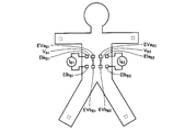
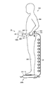
- FIGS. 1A and 1B are diagrams for explaining the measurement principle of the body fat measurement device according to Embodiment 1 of the present invention.
- FIG. 1A is a diagram showing an electrode arrangement when obtaining the bioimpedance of the entire trunk part
- FIG. 1B shows an electrode arrangement when obtaining the bioimpedance of the surface layer portion on the back side of the trunk part.
- FIG. 1A the measurement principle of the body fat measurement device according to the present embodiment will be described with reference to FIGS. 1A and 1B.
- the subject is seen from the back side.
- electrodes EIa A1 and EIa A2 are attached to the surface of the left hand and the surface of the right hand, respectively, in order to obtain the bioimpedance of the entire torso. Electrodes EIb A1 and EIb A2 are also attached to the surface of the left foot and the surface of the right foot of the subject, respectively. Then, four pairs of electrodes arranged along the body axis direction are attached to the back surface of the subject along the lateral width direction of the trunk.
- a total of eight electrodes EVa A1 , EVb A1 , EVa A2 , EVb A2 , EVa A3 , EVb A3 , EVa A4 , EVb A4 are attached to the back surface of the subject.
- a constant current I A passing through the torso is applied to the subject using the electrodes EIa A1 , EIa A2 , EIb A1 , and EIb A2 attached to both hands and both feet.
- a potential difference V A1 is detected using a pair of electrodes EVa A1 and EVb A1 attached to the back surface, and a pair of electrodes EVa A2 attached to the back surface.
- the potential difference V A2 is detected using EVb A2
- the potential difference V A3 is detected using a pair of electrodes EVa A3, EVb A3 attached to the back surface, a pair of electrodes attached to the back surface EVa A4, EVb A4 Is used to detect the potential difference V A4 .
- the bioimpedance Zt of the entire trunk is calculated. At this time, if the bioelectrical impedance Zt is obtained by calculating the average value of the detected four potential differences V A1 , V A2 , V A3 , V A4 , the dispersion of fat distribution inside the trunk portion. The influence of can be reduced.
- the bioimpedance Zt calculated from the potential differences V A1 , V A2 , V A3 , and V A4 measured using such a constant current I A is lean (internal organs, muscles, and skeleton) inside the trunk. The place affected by the amount of increases. Therefore, the area occupied by lean body (hereinafter referred to as the lean body sectional area) Sa in the trunk section of the portion corresponding to the umbilicus position can be estimated based on the bioelectrical impedance Zt.
- Four sets are attached along the width direction of the body. That is, a total of eight electrodes EIa B1 , EIb B1 , EVa B1 , EVb B1 , EVa B2 , EVb B2 , EIa B2 , and EIb B2 are attached to the back surface of the subject as shown in the figure.
- a constant current I B1 that locally passes through the back is applied to the subject using the pair of electrodes EIa B1 and EIb B1 , and locally passes through the back using the pair of electrodes EIa B2 and EIb B2.
- a constant current I B2 is applied to the subject.
- the potential difference V B1 is detected using the pair of electrodes EVa B1 and EVb B1 attached to the back surface, and the pair of electrodes attached to the back surface.
- a potential difference V B2 is detected using EVa B2 and EVb B2 .
- the current values of the two constant currents I B1 and I B2 applied to the subject are the same value.
- the bioimpedance Zs of the surface layer portion on the back side of the trunk is calculated.
- the bioelectrical impedance Zs is obtained by calculating the average value of the detected two potential differences V B1 and V B2 , the influence of the variation in fat distribution in the surface layer portion of the back part of the torso, etc. Can be reduced.
- the electrode to which the current was applied is an electrode for detecting the potential difference and the electrode for which the potential difference was detected is to be the electrode for applying the current, the potential difference is changed at four locations. It is also possible to measure. By doing in this way, influences, such as a variation in subcutaneous fat, can be reduced further.
- the bioimpedance Zs calculated from the potential differences V B1 and V B2 measured using such constant currents I B1 and I B2 is greatly affected by the subcutaneous fat mass. Therefore, the subcutaneous fat cross-sectional area (hereinafter referred to as the subcutaneous fat cross-sectional area) Sb in the cross section including the umbilical position of the trunk can be estimated based on the bioelectrical impedance Zs.
- the visceral fat cross-sectional area Sx is the torso cross-sectional area St and the above-described lean body cross-sectional area. It can be calculated from the following equation (1) using Sa and the subcutaneous fat cross-sectional area Sb.
- the trunk cross-sectional area St can be calculated by using the trunk circumference (so-called waist length) and the horizontal and vertical widths of the trunk.
- the trunk cross-sectional area St can be approximated by the following equation (2).
- the coefficient ⁇ multiplied for the correction is preferably optimized as appropriate according to information such as the subject's sex, age, height, weight, etc. (hereinafter collectively referred to as subject information). That is, the trunk cross-sectional area St can be approximated with higher accuracy by changing the value of the coefficient ⁇ in accordance with the subject information.
- the lean body sectional area Sa can be calculated based on the bioimpedance Zt of the entire trunk.
- the lean body sectional area Sa cannot be accurately calculated only by the bioimpedance Zt of the entire trunk. That is, the lean body sectional area Sa tends to be proportional to the size of the trunk, and in order to calculate the lean body sectional area Sa, it is necessary to further convert the value obtained from the bioimpedance Zt. Therefore, the lean body sectional area Sa is expressed by the following equation (4), for example.
- the value a is a half value of the width of the body part, and is a value related to the size of the body part.
- the value related to the size of the trunk is not limited to the above-mentioned a.
- a ⁇ b may be used so that the horizontal and vertical widths of the trunk are reflected. You may use and a trunk
- drum circumference may be used.
- ⁇ is a coefficient for converting the bioelectrical impedance Zt of the entire trunk part into the lean body sectional area Sa, and is based on, for example, a large number of X-ray CT image samples as in the case where the coefficient ⁇ is obtained.
- the coefficient ⁇ described above is preferably optimized as appropriate according to the subject information, as in the case of the coefficient ⁇ . That is, by changing the value of the coefficient ⁇ according to the subject information, the lean body area Sa can be approximated with higher accuracy.
- the subcutaneous fat cross-sectional area Sb can be calculated based on the bioimpedance Zs of the surface layer portion on the back side of the trunk.
- the subcutaneous fat cross-sectional area Sb cannot be accurately calculated only by the bioimpedance Zs of the surface layer portion on the back side of the trunk. That is, the subcutaneous fat cross-sectional area Sb tends to be proportional to the size of the trunk, and in order to calculate the subcutaneous fat cross-sectional area Sb, it is necessary to further convert the value obtained from the bioelectrical impedance Zs. Therefore, the subcutaneous fat cross-sectional area Sb is expressed by, for example, the following formula (5).
- the value a is a half value of the width of the body part, and is a value related to the size of the body part.
- the value related to the size of the trunk is not limited to the above-mentioned a.
- a ⁇ b may be used so that the horizontal and vertical widths of the trunk are reflected. You may use and a trunk
- drum circumference may be used.
- ⁇ is a coefficient for converting the bioimpedance Zs of the surface layer portion on the back side of the torso to the subcutaneous fat cross-sectional area Sb.
- ⁇ or ⁇ is obtained, The optimum value can be obtained based on a large number of X-ray CT image samples.
- the coefficient ⁇ described above is preferably optimized as appropriate according to the subject information, as in the case of the coefficient ⁇ and the coefficient ⁇ . That is, by changing the value of the coefficient ⁇ according to the subject information, the subcutaneous fat cross-sectional area Sb can be approximated with higher accuracy.
- the torso sectional area St the lean body sectional area Sa calculated based on the bioimpedance Zt of the entire torso, and the back part of the torso
- the visceral fat cross-sectional area Sx is calculated based on the above formula (1), and more specifically, in the above formula (1)
- the visceral fat cross-sectional area Sx is calculated based on the following formula (6) into which the above formulas (3) to (5) are substituted.
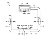
- FIG. 2 is a diagram showing a functional block configuration of the body fat measurement device according to the present embodiment. Next, the configuration of functional blocks of the body fat measurement device according to the present embodiment will be described with reference to FIG.
- the body fat measurement device 1A includes a control unit 10, a constant current generation unit 21, a terminal switching unit 22, a potential difference detection unit 23, and a torso lateral width detection unit 24A.
- the control unit 10 includes an arithmetic processing unit 11, and the arithmetic processing unit 11 includes a bioimpedance measurement unit 12, a body shape information measurement unit 13, and a body composition information acquisition unit 14.
- the control unit 10 is configured by, for example, a CPU (Central Processor Unit), and is a part for controlling the entire body fat measurement device 1A. Specifically, the control unit 10 outputs a command to each functional block described above, receives input of various information from each functional block described above, and performs various arithmetic processes based on the received various information. Or Of these, the various arithmetic processes are performed by the arithmetic processing unit 11 provided in the control unit 10 described above.
- a CPU Central Processor Unit
- the plurality of electrodes described above include hand electrodes HR and HL as upper limb electrodes arranged in contact with the surface of the subject's upper limb, and back electrodes BU1 to BU4 and BL1 to BL4 arranged in contact with the subject's back surface. And foot electrodes FR and FL as lower limb electrodes arranged in contact with the surface of the lower limbs of the subject.
- the hand electrodes HR and HL are arranged in contact with the subject's palm
- the foot electrodes FR and FL are arranged in contact with the sole of the subject's foot. Further, as shown in FIGS.
- the back electrodes BU1 to BU4 and BL1 to BL4 are arranged in contact with each other in a state of being aligned with the back surface of the subject.
- the hand electrodes HR and HL, the back electrodes BU1 to BU4, BL1 to BL4, and the foot electrodes FR and FL are all electrically connected to the terminal switching unit 22 described above.
- the terminal switching unit 22 is configured by, for example, a relay circuit, and electrically connects a specific electrode selected from the plurality of electrodes described above and the constant current generation unit 21 based on a command input from the control unit 10.
- a specific electrode selected from the plurality of electrodes described above and the potential difference detection unit 23 are electrically connected.
- the electrode electrically connected to the constant current generating unit 21 by the terminal switching unit 22 functions as a constant current application electrode, and is electrically connected to the potential difference detecting unit 23 by the terminal switching unit 22.
- the electrode functions as a potential difference detection electrode.
- each of the plurality of electrodes HR, HL, BU1 to BU4, BL1 to BL4, FR, FL described above is shown in FIG. 1A.
- the constant current generation unit 21 generates a constant current based on a command input from the control unit 10 and supplies the generated constant current to the above-described constant current application electrode via the terminal switching unit 22.
- a high-frequency current for example, 50 kHz, 500 ⁇ A
- a constant current is applied to the subject via the constant current application electrode.
- the potential difference detection unit 23 detects a potential difference between electrodes (that is, potential difference detection electrodes) electrically connected to the potential difference detection unit 23 by the terminal switching unit 22 and outputs the detected potential difference to the control unit 10. Thereby, the potential difference between the potential difference detection electrodes in a state where the above-described constant current is applied to the subject is detected.
- the trunk width detecting unit 24A is a detection part for measuring the width of the torso of the subject in a non-contact manner, and is constituted by a distance measuring sensor such as an optical sensor.
- drum vertical width detection part 24B is a detection site
- the trunk width detection unit 24A and the trunk vertical width detection unit 24B output a signal corresponding to the detection value to the body shape information measurement unit 13.
- the body width detection unit 24A and the body length detection unit 24B include ultrasonic waves and electromagnetic waves (laser light, light in various wavelength bands including visible light, radio waves, and magnetism).
- various non-contact distance measuring sensors using an electric field or the like can be used, and contact type distance measuring sensors can also be used.
- the subject information input unit 25 is a part for obtaining information about the subject used in the arithmetic processing performed by the arithmetic processing unit 11, and is configured by, for example, a key that can be pressed by the subject.
- the subject information includes at least one of information such as the sex, age, height, and weight of the subject as described above.
- the subject information input unit 25 receives input of subject information and outputs the received subject information to the control unit 10.
- the subject information input unit 25 is not necessarily an essential configuration in light of the present invention, and depends on whether or not it is necessary to use the subject information in the arithmetic processing performed by the arithmetic processing unit 11. The presence or absence is determined.
- trunk width detection unit 24A and trunk vertical width detection unit 24B are not provided to measure the horizontal width and vertical width of the trunk, but instead to the trunk circumference through the subject information input unit 25. It is also possible to configure so that the arithmetic processing unit performs an operation using the input.
- the arithmetic processing unit 11 includes the bioelectrical impedance measurement unit 12, the body shape information measurement unit 13, and the body composition information acquisition unit 14 as described above.
- the body composition information acquisition unit 14 includes a visceral fat mass calculation unit 14a and a subcutaneous fat mass calculation unit 14b.
- the bioelectrical impedance measurement unit 12 calculates bioelectrical impedance based on the signal input from the potential difference detection unit 23 and outputs this to the body composition information acquisition unit 14.
- the body shape information measurement unit 13 calculates the body width and length of the subject's torso based on signals input from the body width detection unit 24A and the body length detection unit 24B, and obtains the body composition information acquisition unit 14 Output to.
- the body composition information acquisition unit 14 inputs the bioelectrical impedance input from the bioelectrical impedance measurement unit 12, the horizontal and vertical widths of the trunk input from the body shape information measurement unit 13, and, in some cases, in addition to subject information input
- the body composition information is calculated and acquired based on the subject information input from the unit 25. More specifically, the visceral fat mass calculation unit 14a calculates the visceral fat mass, and the subcutaneous fat mass calculation unit 14b calculates the subcutaneous fat mass.
- the display unit 26 is configured by, for example, an LCD (Liquid Crystal Display) or the like, and displays the body composition information calculated by the body composition information acquisition unit 14 described above. More specifically, the visceral fat mass calculated by the visceral fat mass calculation unit 14a and the subcutaneous fat mass calculated by the subcutaneous fat mass calculation unit 14b are based on the signal output from the control unit 10 and the display unit 26. Is displayed.
- the visceral fat mass is displayed, for example, as a visceral fat cross-sectional area
- the subcutaneous fat mass is displayed, for example, as a subcutaneous fat cross-sectional area.
- the operation unit 27 is a part for the subject to input a command to the body fat measurement device 1A, and is configured by, for example, a button that can be pressed by the subject.
- the operation unit 27 includes various operation buttons such as a power button and a measurement button.
- the power supply unit 28 is a part for supplying power to the control unit 10, and an internal power source such as a battery or an external power source such as a commercial power source is used.
- the memory unit 29 is configured by, for example, a RAM (Random Access Memory), a ROM (Read Only Memory), or the like, and is a part for storing various data, programs, and the like related to the body fat measurement device 1A.
- the memory unit 29 stores, for example, the above-described subject information, calculated body composition information, a body composition information measurement program for performing a body composition information measurement process described later, and the like.
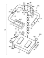
- FIG. 3 is a perspective view showing the non-contained state of the body fat measurement device according to the present embodiment
- FIG. 4 is a perspective view showing the accommodated state.
- FIG. 5 is a top view of the mounting unit shown in FIGS. 3 and 4. Next, with reference to these FIG. 3 thru
- the body fat measurement device 1A includes an attachment unit 100A as a trunk width measurement unit and a base unit 200A.
- the mounting unit 100 ⁇ / b> A has a frame shape that can be disposed so as to surround the torso of the subject in the mounting state described later.
- the base unit 200A has a trapezoidal shape on which a subject can ride.
- the mounting unit 100 ⁇ / b> A and the base unit 200 ⁇ / b> A are connected by a connection cable 40 for electrically connecting an electric circuit provided therein.
- the mounting unit 100A includes a rod-shaped rear frame portion 111, a rod-shaped right frame portion 112, a rod-shaped left frame portion 113, and a rod-shaped front frame portion 114.
- the frame 110 has a frame-like outer shape that is substantially rectangular when viewed from above, and has a hollow opening that allows the subject to enter the inside (that is, to insert the torso).
- the hollow opening is defined by the rear frame portion 111, the right frame portion 112, the left frame portion 113, and the front frame portion 114 described above.
- the left frame portion 113 and the front frame portion 114 are discontinuous, and the display unit 130 described above is attached to the end of the front frame portion 114 adjacent to the discontinuous portion. It has been.
- the electrode support 120 is disposed at a substantially central portion of the rear frame portion 111 of the frame 110 so as to protrude inward.
- the electrode support 120 is configured by a curved plate that is bent so that both end portions thereof are positioned forward and the central portion thereof is positioned rearward.
- the above-mentioned back electrodes BU1 to BU4 and BL1 to BL4 are provided on the front surface 121 of the electrode support 120 so that the back electrodes BU1 to BU4 and BL1 to BL4 are preferably exposed. It protrudes slightly from the front surface 121 of the body 120.
- the electrode support 120 is positioned on the front surface of the rear frame-shaped portion 111 so that the contact surfaces of the back electrodes BU1 to BU4 and BL1 to BL4 with respect to the back surface of the subject face forward in the mounted state described later. Installed.
- the electrode support 120 is attached to the rear frame portion 111 of the frame 110 via a connection portion 115 including, for example, a ball joint.
- the electrode support 120 is supported by the rear frame portion 111 so as to be swingable.
- the swinging direction is preferably limited so that the electrode support 120 can swing only in a direction swinging left and right in a horizontal plane.
- the back electrodes BU1 to BU4 and BL1 to BL4 provided on the front surface 121 of the electrode support 120 are brought into contact with the back of the subject reliably and with an appropriate pressing force in the mounting state described later. be able to.
- the electrode support 120 may be elastically supported by the rear frame portion 111 by providing the connection portion 115 with an elastic body such as a spring.
- an elastic body such as a spring.
- the hand electrode HR described above is provided at the substantially central portion of the right frame portion 112 of the frame 110.
- the hand electrode HR is exposed and positioned on the surface of the right frame portion 112 of the frame 110.
- the right frame portion 112 of the portion of the frame 110 where the hand electrode HR is provided is formed in a rod shape so that it can be gripped with the right hand.
- the contact surface of the hand electrode HR with the palm of the right hand of the subject is preferably disposed so as to face mainly the outside of the frame 110.
- an optical sensor as the body width detection unit 24A described above is embedded in the substantially central portion of the right frame portion 112 of the frame 110, and the right side portion of the portion where the optical sensor is embedded.
- a detection window 24 ⁇ / b> A ⁇ b> 1 is provided in an inner portion of the frame-like portion 112.
- This detection window 24A1 is configured by a member that transmits light emitted from the optical sensor.
- a measurement button 27 a is provided at a predetermined position of the right side frame portion 112 of the frame body 110.
- the measurement button 27a is preferably provided at a position adjacent to the hand electrode HR.
- the above-described hand electrode HL is provided at a substantially central portion of the left frame portion 113 of the frame 110.
- the hand electrode HL is located exposed on the surface of the left frame portion 113 of the frame 110.
- the left-side frame-like portion 113 of the portion of the frame 110 where the hand electrode HL is provided is formed in a rod shape so that it can be gripped with the left hand.
- the contact surface of the hand electrode HL with the palm of the left hand of the subject is preferably disposed so as to face mainly the outside of the frame 110.
- an optical sensor serving as the trunk width detecting portion 24 ⁇ / b> A described above is embedded in the substantially central portion of the left frame portion 113 of the frame 110, and the optical sensor is A detection window portion 24A2 is provided in an inner portion of the left-side frame portion 113 of the embedded portion.
- the detection window 24A2 is configured by a member that transmits light emitted from the optical sensor.
- the display unit portion 130 is attached to the front frame portion 114 of the frame 110 as described above.
- the display unit 26 is provided on the upper surface of the display unit 130, and the subject information input unit 25 and the measurement button 27 a are further provided on the upper surface of the display unit unit 130 adjacent to the display unit 26.
- An operation unit 27 other than the above is provided.
- the display unit 130 is preferably disposed in front of the subject in the mounted state. Therefore, the display unit 130 is located in front of the electrode support 120 described above (that is, substantially in the left-right direction of the frame 110). (Central part).
- the display unit unit 130 is embedded with the above-described optical sensor as the trunk vertical width detection unit 24 ⁇ / b> B, and the display unit of the portion where the optical sensor is embedded.
- a detection window 24 ⁇ / b> B ⁇ b> 1 is provided on the rear side portion of the portion 130.
- the detection window 24B1 is formed of a member that transmits light emitted from the optical sensor.
- the base unit 200 ⁇ / b> A includes a box-shaped base part 210 and predetermined surfaces of the front part, the rear face, the right side face, and the left side face (that is, the peripheral surface of the base part 210). And a support part 220 that protrudes from the position toward the outside of the base part 210.
- the base 210 has an upper surface 211 on which a subject rides, and the foot electrodes FR and FL described above are provided at predetermined positions on the upper surface 211, respectively.
- the foot electrodes FR and FL are located exposed on the upper surface of the base 210.
- the contact surfaces of the foot electrodes FR and FL that are in contact with the sole of the right foot and the sole of the left foot of the subject are configured to face upward.
- the support portion 220 is a portion for supporting and storing the mounting unit 100 ⁇ / b> A in the storage state, and includes a rear frame portion 111, a right frame portion 112, and a left frame in the frame 110.
- the shape portion 113 and the front frame shape portion 114 can be received and supported.
- the frame 110 of the mounting unit 100A is disposed so as to surround the base 210 of the base unit 200A. A portion of the base 210 is accommodated in the hollow opening defined by the above.
- connection cable 40 for connecting the mounting unit 100A and the base unit 200A is stored in the base unit 200A.
- a reel body capable of winding the connection cable 40 may be provided inside the base unit 200A.
- the control unit 10, the constant current generation unit 21, the terminal switching unit 22, the potential difference detection unit 23, the memory unit 29, and the like illustrated in FIG. 2 may be provided inside the mounting unit 100A, or the base unit 200A. It may be provided inside. Further, in the body fat measurement device 1A in the present embodiment, the subject information input unit 25, the display unit 26, and the operation unit 27 are provided in the mounting unit 100A, but these are provided in the base unit 200A. Also good.
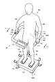
- FIG. 6 to 8 are diagrams for explaining a procedure to be taken by the subject when performing measurement using the body fat measurement device according to the present embodiment.
- FIG. 9 and FIG. 10 are diagrams showing a mounting state of the mounting unit of the body fat measurement device according to the present embodiment.
- the subject 300 when body fat mass is measured using the body fat measurement device 1A according to the present embodiment, first, the subject 300 first has the base unit 200A of the body fat measurement device 1A in the housed state. Get on. At this time, in the subject 300, the sole of the right foot 301 contacts the foot electrode FR provided on the platform unit 200A, and the sole of the left foot 302 contacts the foot electrode FL provided on the platform unit 200A. To do.
- the subject 300 takes a posture in which the upper body is bent and squats, holds the right side frame portion 112 of the mounting unit 100 ⁇ / b> A with the right hand 303, and uses the mounting unit with the left hand 304.
- the left frame portion 113 of 100A is gripped.
- the subject 300 makes the palm of the right hand 303 contact the hand electrode HR provided in the mounting unit 100A, and the palm of the left hand 304 contacts the hand electrode HL provided in the mounting unit 100A. .
- the subject 300 raises his / her upper body and takes a standing posture while maintaining the state of holding the mounting unit 100 ⁇ / b> A. At this time, the subject 300 maintains the state where the sole of the right foot 301 and the foot electrode FR are in contact with each other and the foot sole of the left foot 302 and the foot electrode FL are in contact without changing the stepping position. .
- the mounting unit 100 ⁇ / b> A is lifted, and the trunk 305 of the subject 300 is positioned in the hollow opening of the mounting unit 100 ⁇ / b> A and is surrounded by the frame 110.
- the connection cable 40 is pulled out from the base unit 200A when the mounting unit 100A is lifted.
- the subject 300 has the mounting unit 100 so that the front surface 121 of the electrode support 120 provided in the mounting unit 100A is pressed against the back surface (more specifically, the back waist surface).
- the position of the mounting unit 100A is adjusted by moving the mounting unit 100A in the direction of arrow C in the figure while holding the 100A. At this time, the subject 300 is careful to arrange the frame 110 of the mounting unit 100A horizontally.
- the wearing state of the wearing unit 100A as shown in FIGS. 9 and 10 is realized, and the measurement of the body fat mass can be started.
- the subject 300 may press the measurement button 27a with the thumb of the right hand 303.
- the test subject 300 is requested
- the timing of turning on the power button is not particularly limited, but it is preferable that the power button is turned on at a timing before the subject 300 takes a squatting posture and grips the mounting unit 100A.
- the optical sensor as the vertical width detection unit 24B is positioned. Therefore, the light emitted from the pair of optical sensors serving as the trunk width detection unit 24A passes through the detection window portions 24A1 and 24A2 and the right side surface (that is, the right flank surface) of the trunk 305 of the subject 300 and the trunk, respectively.
- the left side surface of the unit 305 (that is, the left flank surface) can be irradiated, and the light emitted from the optical sensor serving as the trunk vertical width detection unit 24B passes through the detection window unit 24B1 to the trunk unit 305 of the subject 300. It is possible to irradiate the front surface (that is, near the umbilicus position of the abdomen).
- the distance A1 detected by the pair of photosensors as the trunk width detector 24A that is, the right frame portion 112 and the right side of the trunk 305 of the subject 300.
- Distance) and distance A2 ie, the distance between the left side frame portion 113 and the left side surface of the torso 305 of the subject 300
- a predetermined distance A ie, right side frame shape portion 112
- the lateral width 2a of the torso 305 of the subject 300 can be calculated.
- the distance B1 that is, the distance between the rear surface of the display unit 130 and the front surface of the torso 305 of the subject 300 detected by the optical sensor as the torso length detection unit 24B
- a predetermined distance B that is, the distance between the rear surface of the display unit 130 and the horizontal center position of the front surface 121 of the electrode support 120
- the vertical direction of the trunk 305 of the subject 300 is used.
- the width 2b can be calculated.
- FIG. 11 is a flowchart showing processing of the control unit of the body fat measurement device according to the present embodiment. Next, a series of processes executed in the control unit of the body fat measurement device according to the present embodiment will be described with reference to FIG.
- the processing shown in the flowchart of FIG. 11 is stored in advance in the memory unit 29 as a program, and the control unit 10 including the arithmetic processing unit 11 reads out and executes this program, thereby measuring the visceral fat cross-sectional area.
- the subcutaneous fat cross-sectional area measurement process is realized by the control unit 10.
- control unit 10 first receives input of subject information (step S1).
- the subject information received here is temporarily stored in the memory unit 29, for example.
- control unit 10 determines whether or not there is an instruction to start measurement (step S2). Control unit 10 stands by until an instruction to start measurement is received (NO in step S2), and when an instruction to start measurement is detected (YES in step S2), the process proceeds to the next process.
- the instruction to start the measurement is when the subject presses the measurement button 27a.
- control unit 10 measures the horizontal width and vertical width of the trunk (step S3). Specifically, the control unit 10 determines the body width 2a and the height 2b of the torso of the subject in the body shape information measurement unit 13 based on signals input from the body width detection unit 24A and the body length detection unit 24B. get. The acquired width 2a and length 2b of the torso of the subject are temporarily stored in the memory unit 29.
- control unit 10 performs electrode setting (step S4). Specifically, the control unit 10 outputs a command to switch the electrodes to the terminal switching unit 22, and based on this, the terminal switching unit 22 outputs a plurality of electrodes HR, HL, BU1 to BU4. Each of BL1 to BL4, FR, and FL is set like each electrode shown in FIG. 1A.
- control unit 10 applies a constant current between the constant current application electrodes (step S5). Specifically, the control unit 10 outputs a command to generate a constant current to the constant current generation unit 21, and based on this, the constant current generation unit 21 outputs the constant current application electrode shown in FIG. 1A. A constant current I A generated between them is applied.
- control unit 10 detects a potential difference between the potential difference detection electrodes (step S6). Specifically, the control unit 10 outputs a command to detect the potential difference to the potential difference detection unit 23, and based on this, the potential difference detection unit 23 outputs the potential difference V between the potential difference detection electrodes shown in FIG. 1A. A 1 , V A2 , V A3 , and V A4 are detected and output to the bioimpedance measurement unit 12.
- control unit 10 calculates the bioelectrical impedance Zt (step S7). Specifically, the control unit 10 calculates the bioimpedance Zt in the bioimpedance measurement unit 12 based on the signal input from the potential difference detection unit 23. The calculated bioelectrical impedance Zt is temporarily stored in the memory unit 29.
- control unit 10 sets electrodes again (step S8). Specifically, the control unit 10 outputs a command to switch the electrodes to the terminal switching unit 22, and based on this, the terminal switching unit 22 outputs a plurality of electrodes HR, HL, BU1 to BU4. Each of BL1 to BL4, FR, and FL is set like each electrode shown in FIG. 1B.
- control unit 10 applies a constant current between the constant current application electrodes (step S9). Specifically, the control unit 10 outputs a command to generate a constant current to the constant current generation unit 21, and based on this, the constant current generation unit 21 outputs the constant current application electrode shown in FIG. 1B. Constant currents I B1 and I B2 generated between them are respectively applied.
- control unit 10 detects a potential difference between the potential difference detection electrodes (step S10). Specifically, the control unit 10 outputs a command to the potential difference detection unit 23 to detect the potential difference, and based on this, the potential difference detection unit 23 outputs the potential difference V between the potential difference detection electrodes shown in FIG. 1B. B1 and VB2 are detected and output to the bioimpedance measurement unit 12.
- control unit 10 calculates the bioelectrical impedance Zs (step S11). Specifically, the control unit 10 calculates the bioimpedance Zs in the bioimpedance measurement unit 12 based on the signal input from the potential difference detection unit 23. The calculated bioelectrical impedance Zs is temporarily stored in the memory unit 29.
- the control unit 10 calculates a visceral fat cross-sectional area and a subcutaneous fat cross-sectional area, respectively (step S12). Specifically, the control unit 10 is based on the lateral width 2a and the vertical width 2b of the trunk detected in step S3, the bioelectrical impedance Zt calculated in step S7, and the bioelectrical impedance Zs calculated in step S11. Then, the visceral fat mass calculating unit 14a calculates the visceral fat cross-sectional area Sx as the visceral fat mass, and the subcutaneous fat mass calculating unit 14b calculates the subcutaneous fat cross-sectional area Sb as the subcutaneous fat mass. The calculated visceral fat cross-sectional area Sx and subcutaneous fat cross-sectional area Sb are temporarily stored in the memory unit 29.
- control part 10 displays a measurement result (step S13). Specifically, the control unit 10 outputs a command to display the visceral fat cross-sectional area Sx and the subcutaneous fat cross-sectional area Sb calculated in step S12 on the display unit 26, and based on this, the display unit 26 displays the command. The measurement result is displayed.
- the body fat measurement device 1A ends the visceral fat cross section measurement process and the subcutaneous fat cross section measurement process.
- a typical value of the bioelectrical impedance Zt is about 5 ⁇ , and a typical value of the bioelectrical impedance Zs is about 80 ⁇ .
- the mounting unit 100A provided with a detachable attachment to the base unit 200A for bringing the foot electrodes FR, FL into contact with the soles of the subject's feet when the subject rides, so that the mounting unit is in the stored state.
- 100A is stored in the base unit 200A, and the body fat amount such as the visceral fat amount can be measured in a non-storage state in which the mounting unit 100A is removed from the base unit 200A. Therefore, it is possible to adopt a state in which the device is greatly miniaturized at the time of storage, and a user-friendly body fat measurement device can be obtained without requiring a large storage place.
- the hand electrodes HR and HL can be placed in contact with the palm of the right hand and the left hand, respectively, and the mounting unit 100A is gripped with the right hand and the left hand.
- the back electrodes BU1 to BU4 and BL1 to BL4 provided in the mounting unit 100A can be placed in contact with each other while pressed against the back surface. It becomes possible to actually measure the vertical width. Therefore, the operation of the subject required for the measurement of the body fat amount is simplified, and not only can the body fat amount be measured with high accuracy and easily by a simple operation, but also the subject himself is an assistant. Measurements can be performed by one person without obtaining such cooperation.
- the back electrode and the back surface of the subject thus, it is difficult to maintain a stable contact, and therefore, it is usually necessary for the subject to take a supine posture or a prone posture in order to stabilize the contact.
- the apparatus when the apparatus is configured in such a manner, it becomes very difficult for the subject himself / herself to perform measurement by himself / herself without the assistance of an assistant or the like, and as a result, the apparatus should be used at home. It becomes a body fat measurement device that can not be.
- the trunk width and the trunk width can be measured with high accuracy. Therefore, in the body fat measurement device 1A according to the present embodiment, the operation of the subject required for the measurement of the body fat mass is simplified, and the body fat mass can be measured with high accuracy with a simple operation. Not only can the measurement be performed easily, but the test can be performed by one person without the assistance of an assistant.
- a body such as visceral fat mass or subcutaneous fat mass in a state where the back electrodes BU1 to BU4 and BL1 to BL4 are placed in contact with the back surface of the subject. Since the amount of fat can be measured, current is not applied locally to the abdomen where the thickness of the subcutaneous fat is relatively thin, but current is applied locally to the back where the thickness of the subcutaneous fat is relatively thick. It is possible to measure the body fat mass with higher accuracy.
- a body fat measuring device 1A in the present embodiment a body fat measuring device that is easy to use at home and that can easily and accurately measure body fat mass such as visceral fat mass and subcutaneous fat mass. can do. Therefore, by using the body fat measuring device 1A, it is possible to obtain indices for health management on a daily basis.
- FIG. 12 is a perspective view showing the non-contained state of the body fat measurement device according to Embodiment 2 of the present invention
- FIG. 13 is a perspective view showing the accommodated state.
- the specific structure of the body fat measuring device in this Embodiment is demonstrated. Note that the measurement principle of the body fat measurement device according to the present embodiment and the arithmetic processing performed by the control unit are the same as those of the body fat measurement device according to the first embodiment of the present invention described above.
- body fat measurement device 1B in the present embodiment surrounds the torso of the subject in the wearing state, similarly to body fat measurement device 1A in Embodiment 1 of the present invention described above.
- a mounting unit 100B having a frame-like shape that can be arranged in this manner, and a base unit 200B having a trapezoidal shape on which a subject can ride is provided.
- the support unit on which the base unit 200B protrudes from the peripheral surface is provided.
- the step part 212 is provided by forming a step along the periphery of the upper surface 211 of the base unit 200B.
- the stepped portion 212 is a part for supporting and storing the mounting unit 100 ⁇ / b> B in the storage state, and includes a rear frame-shaped portion 111, a right-side frame-shaped portion 112, and a left-side frame.
- the shape portion 113 and the front frame shape portion 114 can be received and supported.
- the frame 110 of the mounting unit 100B is disposed so as to surround the base portion 210 of the base unit 200B. A portion of the base 210 is accommodated in the hollow opening defined by the above.
- an electrode support accommodating step 212 a is provided at a predetermined position of the step 212 that receives and supports the rear frame 111 of the frame 110.
- the electrode support 120 is received and supported by the electrode support storage step 212a.
- a display unit accommodating step 212b is provided at a predetermined position of a portion of the step 212 that receives and supports the front frame-like portion 114 of the frame 110.
- the unit unit 130 is received and supported by the display unit housing step 212b.
- FIG. 14 is a perspective view showing a non-contained state of the body fat measurement device according to Embodiment 3 of the present invention
- FIG. 15 is a perspective view showing the accommodated state.
- the specific structure of the body fat measuring device in this Embodiment is demonstrated. Note that the measurement principle of the body fat measurement device according to the present embodiment and the arithmetic processing performed by the control unit are the same as those of the body fat measurement device according to the first embodiment of the present invention described above.
- body fat measurement device 1 ⁇ / b> C in the present embodiment surrounds the torso of the subject in the mounted state, similarly to body fat measurement device 1 ⁇ / b> A in Embodiment 1 of the present invention described above.
- the mounting unit 100 ⁇ / b> C having a frame shape that can be arranged in this manner, and the base unit 200 ⁇ / b> C having a trapezoidal shape on which a subject can ride is provided.
- the body fat measurement device 1C according to the present embodiment unlike the body fat measurement device 1A according to the first embodiment of the present invention described above, the support unit on which the base unit 200C protrudes from the peripheral surface is provided. Instead, a recess 213 is provided by forming a groove in a portion excluding the periphery of the upper surface 211 of the base unit 200C.
- the recess 213 is a part for supporting and storing the mounting unit 100 ⁇ / b> C in the storage state.
- Each of the portions 113 and the front frame portion 114 has a shape capable of receiving and supporting.
- the frame 110 of the mounting unit 100C is disposed so as to surround the central portion of the base 210 of the base unit 200C. A part of the base 210 is accommodated in the hollow opening defined by the frame 110.
- an electrode support housing recess 213a is provided at a predetermined position of a portion of the recess 213 that receives and supports the rear frame portion 111 of the frame 110, In the storage state, the electrode support 120 is received and supported by the electrode support storage recess 213a.
- a display unit housing recess 213b is provided at a predetermined position of a portion of the recess 213 that receives and supports the front frame-like portion 114 of the frame 110. In the storage state, the display unit receiving recess 213b is provided. The unit 130 is received and supported by the display unit unit accommodating recess 213b.
- the body fat measurement device 1C in the present embodiment described above By using the body fat measurement device 1C in the present embodiment described above, the same effects as those described in the first embodiment of the present invention described above can be obtained, and the mounting unit 100C in the stored state. Since most of the configuration is accommodated in the base unit 200C, the mounting unit 100C is prevented from being damaged during storage.
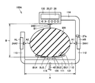
- FIG. 16 is a perspective view showing a storage structure of a body fat measurement device according to Embodiment 4 of the present invention.
- a specific structure of the body fat measurement device according to the present embodiment will be described with reference to FIG. Note that the measurement principle of the body fat measurement device according to the present embodiment and the arithmetic processing performed by the control unit are the same as those of the body fat measurement device according to the first embodiment of the present invention described above.
- the body fat measurement device 1D in the present embodiment is arranged so as to surround the torso of the subject in the wearing state, similarly to the body fat measurement device 1A in the first embodiment of the present invention described above.
- a mounting unit 100D having a frame shape that can be mounted, and a base unit 200D having a trapezoidal shape on which a subject can ride.
- the support unit on which the base unit 200D protrudes from the peripheral surface is provided.
- the base unit 210 of the base unit 200D is configured by a box that can be opened and closed.
- the base part 210 of the base unit 200D has a top plate part 214A constituting the upper surface thereof and a substantially rectangular parallelepiped box part 214B having an upper surface opening.
- the top plate portion 214A is attached to the box portion 214B by a hinge 214a so as to be rotatable along the direction of arrow D in the figure, and closes the upper surface opening of the box portion 214B in the closed state.
- a storage chamber 214C having a size capable of storing the mounting unit 100D is provided inside the box portion 214B.
- foot electrodes FR and FL are provided as electrodes for the lower limbs on the top surface of the top plate portion 214A.
- the mounting unit 100D is stored in the storage unit 214D by storing the mounting unit 100D in the storage chamber 214C of the base unit 200D.
- the top plate portion 214A can close the upper surface opening of the box portion 214B described above, whereby the mounting unit 100D is accommodated in the base unit 200D without being exposed to the outside.
- a connection cable 40 (see FIG. 3 and the like) for connecting the mounting unit 100D and the base unit 200D is connected to the mounting unit 100D and the base unit. It is preferable to be detachable from at least one of 200D.
- the body fat measurement device 1D in the present embodiment described above By using the body fat measurement device 1D in the present embodiment described above, the same effects as those described in the first embodiment of the present invention described above can be obtained, and the mounting unit 100D in the housed state. Therefore, the mounting unit 100D is prevented from being damaged during storage.
- FIG. 17 is a perspective view showing a storage structure of the body fat measurement device according to Embodiment 5 of the present invention.
- a specific structure of the body fat measurement device according to the present embodiment will be described with reference to FIG. Note that the measurement principle of the body fat measurement device according to the present embodiment and the arithmetic processing performed by the control unit are the same as those of the body fat measurement device according to the first embodiment of the present invention described above.
- the body fat measurement device 1E in the present embodiment is arranged so as to surround the torso of the subject in the wearing state, similarly to the body fat measurement device 1A in the first embodiment of the present invention described above.
- the support unit on which the base unit 200E is positioned to protrude from the peripheral surface is provided.
- the base unit 210E of the base unit 200E is configured by a box whose one surface is open.
- the base portion 210 of the base unit 200E is configured as a substantially rectangular parallelepiped box having a front opening having an opening 215a on the front surface thereof.
- the opening 215a is configured to be sized so that the mounting unit 100E can be taken in and out, and a storage chamber 215 having a size capable of storing the mounting unit 100E is provided inside the base 210.
- the mounting unit 100E is stored in the storage unit 215 of the base unit 200E through the opening 215a, so that the mounting unit 100E is stored in the base unit 200E.
- a connection cable 40 (see FIG. 3) for connecting the mounting unit 100E and the base unit 200E is connected to the mounting unit 100E and the base unit. It is preferable to be configured to be detachable from at least one of 200E.
- the body fat measurement device 1E in the present embodiment described above By using the body fat measurement device 1E in the present embodiment described above, the same effects as those described in the first embodiment of the present invention described above can be obtained, and further, the mounting unit 100E in the housed state. Since most of the configuration is housed in the base unit 200E, the mounting unit 100E is prevented from being damaged during storage.
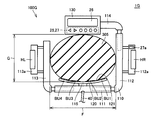
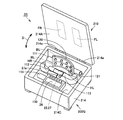
- FIG. 18 is a perspective view showing a storage structure for a body fat measurement device according to Embodiment 6 of the present invention.
- a specific structure of the body fat measurement device according to the present embodiment will be described with reference to FIG. Note that the measurement principle of the body fat measurement device according to the present embodiment and the arithmetic processing performed by the control unit are the same as those of the body fat measurement device according to the first embodiment of the present invention described above.
- the body fat measurement device 1F in the present embodiment is arranged so as to surround the torso of the subject in the wearing state, similarly to the body fat measurement device 1A in the first embodiment of the present invention described above.
- the support unit on which the base unit 200F is positioned to protrude from the peripheral surface is provided.
- the base unit 210F of the base unit 200F is configured by a box body having a drawer that can be taken in and out.
- the base unit 210F of the base unit 200F has a substantially rectangular parallelepiped box portion 216A having a front opening having an opening 216a on the front surface thereof, and its insertion and removal through the opening 216a. And a drawer 216 ⁇ / b> B with an upper surface opening configured so as to be possible.
- a storage chamber 216C having a size capable of storing the mounting unit 100F is provided inside the drawer 216B.
- the mounting unit 100F is stored in the storage chamber 216C of the drawer 216B and the drawer 216B is stored in the box 216A, whereby the mounting unit 100F is stored in the base unit 200F.
- the mounting unit 100F is accommodated in the base unit 200F without being exposed to the outside.
- a connection cable 40 (see FIG. 3) for connecting the mounting unit 100F and the base unit 200F is connected to the mounting unit 100F and the base unit. It is preferable to be configured to be detachable from at least one of 200F.
- the body fat measurement device 1F in the present embodiment described above By using the body fat measurement device 1F in the present embodiment described above, the same effects as those described in the first embodiment of the present invention described above can be obtained, and the mounting unit 100F in the stored state. Therefore, the mounting unit 100F is prevented from being damaged during storage.
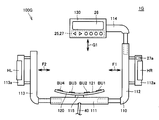
- FIG. 19 is a top view of the mounting unit of the body fat measurement device according to the seventh embodiment of the present invention
- FIG. 20 is a diagram illustrating a mounting state of the mounting unit of the body fat measurement device according to the present embodiment.
- the body fat measurement device 1G in the present embodiment surrounds the torso of the subject in the wearing state, similarly to the body fat measurement device 1A in the first embodiment of the present invention described above.
- a mounting unit 100G having a frame-like shape that can be arranged in this manner, and a platform unit 200G (see FIG. 21) having a trapezoidal shape on which a subject can ride.
- the mounting unit 100G of the body fat measurement device 1G includes a rear frame portion 111, a right frame portion 112, a left frame portion 113, and a front frame of the frame 110.
- Each of the rear frame-shaped portion 111, the right-side frame-shaped portion 112, the left-side frame-shaped portion 113, and the front-frame-shaped portion 114 is an adjacent frame-shaped portion. They are connected so that they can move relative to each other.
- the right frame portion 112 is configured to be movable along the arrow F1 direction in the figure with respect to the rear frame portion 111
- the left frame portion 113 is configured to be the rear frame portion 111
- the front frame-like portion 114 is configured to be movable in the direction of the arrow G1 in the drawing with respect to the right-side frame-like portion 112.
- the handle portions 112a and 113a are provided outward from the right side frame portion 112 and the left side frame shape portion 113, respectively. 112a and 113a are provided so that the hand electrodes HR and HL are exposed, respectively.
- the body fat measurement device 1G does not include the non-contact optical sensor that the body fat measurement device 1A according to Embodiment 1 of the present invention described above has included.
- a movement amount detection sensor for detecting a relative movement amount with respect to the rear frame shape portion 111 of the right side frame shape portion 112 and the left side frame shape portion 113 described above as the trunk width detection portion 24A, and the trunk portion
- a movement amount detection sensor that detects a relative movement amount of the front frame portion 114 to the right frame portion 112 as the vertical width detection portion 24B is provided inside the mounting unit 100A.
- various types such as various encoders typified by a rotary encoder, an optical sensor, and a magnetic sensor can be used.
- the subject's torso 305 is surrounded by the frame 110, and the abdomen, back, and both sides of the torso 305 are all mounted units 100G. In contact with
- the subject maintains the grip portions 112a and 113a with the right hand and the left hand so that the palm of the right hand and the palm of the left hand are in contact with the hand electrodes HR and HL, respectively. Meanwhile, the position of the mounting unit 100G is adjusted such that the front surface 121 of the electrode support 120 provided in the mounting unit 100G is pressed against the back surface.
- the test subject has the right-side frame-shaped portion 112 and the inner-side portion of the right-side frame-shaped portion 112 and the inner-side portion of the left-side frame-shaped portion 113 are in contact with both side portions (that is, both sides) of the trunk portion 305.
- Move the left frame part 113 then remove one hand, move the front frame part 114 so that the back of the display unit 130 is in contact with the front part of the trunk (ie, the abdomen), and then Return the removed hand to its original position.
- the subject adjusts the posture of the mounting unit 100G so that the mounting unit 100G is horizontally disposed.
- the mounting state of the mounting unit 100G as shown in FIG. 15 is realized, and the measurement of the body fat mass can be started.
- the positions of the right side frame portion 112, the left side frame shape portion 113, and the front frame shape portion 114 in the state shown in FIG. 19 are set as the origins, and from the origin position shown in FIG.
- FIG. By measuring the amount of movement until reaching the positions of the rear right frame portion 112, the left frame portion 113 and the front frame portion 114 with the above-described movement amount detection sensor, FIG.
- the horizontal width 2a of the trunk is calculated as the distance F
- the vertical width 2b of the trunk is calculated as the distance G.
- FIG. 21 is a top view showing the storage structure of the body fat measurement device according to the present embodiment. Next, the storage structure of the body fat measurement device according to the present embodiment will be described with reference to FIG.
- the base unit 200G has the same structure as the base unit 200D (see FIG. 16) described in the fourth embodiment of the present invention, and the base unit 200G can be opened and closed. It is composed of a box. That is, the base part 210 of the base unit 200G is constituted by a top plate part 214A constituting the upper surface thereof and a substantially rectangular parallelepiped box part 214B having an upper surface opening, and the top plate part 214A can be rotated by a hinge 214a. Are attached to the box 214B. A storage chamber 214C is provided inside the box portion 214B.
- the frame-shaped portion of the mounting unit 100G (that is, the rear frame-shaped portion 111, the right-side frame-shaped portion 112, the left-side frame-shaped portion). Since the portion 113 and the front frame-like portion 114) are configured to be relatively movable, the outer shape of the mounting unit 100G is minimized by moving these frame-like portions (that is, the state shown in FIG. 21). ), The mounting unit 100G is accommodated in the accommodation chamber 214C. That is, the size of the storage chamber 214C is reduced to a size that can be stored when the outer shape of the mounting unit 100G is minimized. If comprised in this way, also when the structure which accommodates the mounting
- the body fat measurement device 1G in the present embodiment described above the same effects as those described in the first and fourth embodiments of the present invention described above can be obtained, and the storage state is further increased.
- the outer shape of the apparatus can be reduced in size.
- FIG. 22 is a perspective view showing a storage structure of the body fat measurement device according to the eighth embodiment of the present invention.
- the storage structure of the body fat fat measurement device according to the present embodiment will be described. Note that the measurement principle of the body fat measurement device according to the present embodiment and the arithmetic processing performed by the control unit are the same as those of the body fat measurement device according to the first embodiment of the present invention described above.
- the body fat measurement device 1H in the present embodiment is arranged so as to surround the torso of the subject in the wearing state, similarly to the body fat measurement device 1A in the first embodiment of the present invention described above.
- the mounting unit 100H is configured to be disassembled into a plurality of parts. ing. Specifically, as shown in FIG. 22, the mounting unit 100H of the body fat measurement device 1H according to the present embodiment has a frame 110, a rear frame portion 111, a right frame portion 112, a left frame shape. Each of the portion 113 and the front frame-like portion 114 is divided and configured to be disassembled.
- the base unit 200H has the same structure as the base unit 200D (see FIG. 16) described in the fourth embodiment of the present invention described above. It is composed of a box that can be opened and closed. That is, the base part 210 of the base unit 200H is constituted by a top plate part 214A constituting the upper surface thereof and a substantially rectangular parallelepiped box part 214B having an upper surface opening, and the top plate part 214A can be rotated by a hinge 214a. Are attached to the box 214B. A storage chamber 214C is provided inside the box portion 214B.
- the frame-shaped portion (that is, the rear frame-shaped portion 111, the right-side frame-shaped portion 112, the left-side frame-shaped portion 113, and the mounting unit 100H) Since each of the front frame portions 114) is configured to be disassembled, the mounting unit 100H is accommodated in the accommodation chamber 214C in a state where they are disassembled (ie, the state shown in FIG. 22). That is, the size of the storage chamber 214C is reduced to a size that can accommodate these parts after disassembly when the mounting unit 100H is disassembled. If comprised in this way, also when the structure which accommodates the mounting
- the body fat measurement device 1H in the present embodiment described above the same effects as those described in the first and fourth embodiments of the present invention described above can be obtained, and the storage state is further increased.
- the outer shape of the apparatus can be reduced in size.
- the right-side frame-shaped portion 112 and the left-side frame-shaped portion 113 of the frame 110 of the mounting units 100A to 100H serving as the body width measuring units are manually handled.
- the case where the electrodes HR and HL are provided has been described as an example.
- the hand electrodes HR and HL may be provided on the front frame portion 114 of the frame 110, and depending on the case, It is good also as not providing in a mounting unit.
- the frame body 110 of the mounting units 100A to 100H as the trunk width measuring unit is configured with a frame-shaped outer shape that is substantially rectangular when viewed from above.
- the frame 110 may be formed in other shapes, for example, a ring shape, a U shape, a C shape, or the like.
- the base units 200A to 200H since the base units 200A to 200H are provided, the base units 200A to 200H may be provided with a weight measurement function. That is, by providing a load cell or the like as a weight measurement unit for detecting a load on the table unit 200, the weight of the subject on the table unit 200 may be measured by the weight measurement unit. In that case, if the weight information measured by the weight measuring unit provided in the base unit 200 is configured to be input to the control unit 10, the actually measured weight of the subject can be used as subject information for various arithmetic processes. Is possible.
- the calculation process is configured such that the visceral fat cross-sectional area is calculated as the visceral fat mass and the subcutaneous fat cross-sectional area is calculated as the subcutaneous fat mass.
- the amount of visceral fat is calculated by visceral fat volume, visceral fat weight, visceral fat level, etc., which is an index other than the visceral fat cross-sectional area
- the subcutaneous fat amount is calculated by the subcutaneous fat cross-sectional area.
- the calculation process may be configured to be calculated by a subcutaneous fat volume, a subcutaneous fat weight, a subcutaneous fat level, etc., which are other indices.
- 1A to 1H body fat measurement device 10 control unit, 11 arithmetic processing unit, 12 bioimpedance measurement unit, 13 body shape information measurement unit, 14 body composition information acquisition unit, 14a visceral fat mass calculation unit, 14b subcutaneous fat mass calculation unit, 21 constant current generation unit, 22 terminal switching unit, 23 potential difference detection unit, 24A trunk width detection unit, 24B trunk width detection unit, 24A1, 24A2, 24B1, detection window unit, 25 subject information input unit, 26 display unit 27 operation part 27a measurement button 28 power supply part 29 memory part 40 connection cable 100A-100H mounting unit 110 frame body 111 rear frame part 112 right side frame part 112a handle part 113 left side Part frame part, 113a handle part, 114 front frame part, 115 connection part, 120 electrode support, 21 front surface, 130 display unit, 200A to 200H base unit, 210 base, 211 top surface, 212 step, 212a electrode support housing step, 212b display unit housing step, 213 recess, 213a electrode support Accommodating recess, 213
Landscapes
- Health & Medical Sciences (AREA)
- Life Sciences & Earth Sciences (AREA)
- Physics & Mathematics (AREA)
- Medical Informatics (AREA)
- Surgery (AREA)
- Engineering & Computer Science (AREA)
- Biomedical Technology (AREA)
- Heart & Thoracic Surgery (AREA)
- Biophysics (AREA)
- Molecular Biology (AREA)
- Pathology (AREA)
- Animal Behavior & Ethology (AREA)
- General Health & Medical Sciences (AREA)
- Public Health (AREA)
- Veterinary Medicine (AREA)
- General Physics & Mathematics (AREA)
- Nuclear Medicine, Radiotherapy & Molecular Imaging (AREA)
- Radiology & Medical Imaging (AREA)
- Measurement And Recording Of Electrical Phenomena And Electrical Characteristics Of The Living Body (AREA)
Abstract
Description
図1Aおよび図1Bは、本発明の実施の形態1における体脂肪測定装置の測定原理を説明するための図である。ここで、図1Aは、胴部全体の生体インピーダンスを得る場合の電極配置を示した図であり、図1Bは、胴部のうちの背部側の表層部分の生体インピーダンスを得る場合の電極配置を示した図である。まず、これら図1Aおよび図1Bを参照して、本実施の形態における体脂肪測定装置の測定原理について説明する。なお、図1Aおよび図1Bにおいては、被験者をいずれも背中側から見た様子を示している。
ここで、胴部断面積Stは、胴部周囲長(いわゆるウエスト長)や、胴部の横幅および縦幅を用いて算出することが可能である。たとえば、胴部の横幅および縦幅から胴部断面積Stを算出する場合には、胴部の横幅を2a、胴部の縦幅を2bとすれば、胴部の断面形状はおおよそ楕円形であるため、胴部断面積Stは、以下の式(2)で近似できる。
ただし、上記式(2)で近似される胴部断面積Stは、誤差が多く含まれている可能性が高いため、誤差を低減するための係数αをこれに乗ずることによって、より正確な胴部断面積Stを求めることが好ましい。この係数αとしては、たとえば多数のX線CTによる画像サンプルに基づいて、当該画像サンプルから得られる胴部断面積St′と、上記aおよびbとの関係から、St′=α×π×a×bを充足するαの最適値を求めることで得られる。
なお、上記補正のために乗ずる係数αに関しては、被験者の性別、年齢、身長、体重等の情報(以下、これらを総称して被験者情報と称する)に応じて適宜最適化することが好ましい。すなわち、当該被験者情報に応じて上記係数αの値を変更することにより、より高精度に胴部断面積Stが近似できることになる。
ここで、上記aは、上述のとおり胴部の横幅の半分の値であり、胴部の大きさに関係する値である。この胴部の大きさに関係する値としては、上記aに限られず、たとえば胴部の横幅および縦幅が反映されるようにa×bを使用してもよいし、胴部断面積Stを使用してもよいし、胴部周囲長を使用してもよい。
ここで、上記aは、上述のとおり胴部の横幅の半分の値であり、胴部の大きさに関係する値である。この胴部の大きさに関係する値としては、上記aに限られず、たとえば胴部の横幅および縦幅が反映されるようにa×bを使用してもよいし、胴部断面積Stを使用してもよいし、胴部周囲長を使用してもよい。
図2は、本実施の形態における体脂肪測定装置の機能ブロックの構成を示す図である。次に、この図2を参照して、本実施の形態における体脂肪測定装置の機能ブロックの構成について説明する。
図12は、本発明の実施の形態2における体脂肪測定装置の非収納状態を示す斜視図であり、図13は、収納状態を示す斜視図である。次に、これら図12および図13を参照して、本実施の形態における体脂肪測定装置の具体的な構造について説明する。なお、本実施の形態における体脂肪測定装置の測定原理および制御部で実施される演算処理等は、上述した本発明の実施の形態1における体脂肪測定装置のそれらと同様である。
図14は、本発明の実施の形態3における体脂肪測定装置の非収納状態を示す斜視図であり、図15は、収納状態を示す斜視図である。次に、これら図14および図15を参照して、本実施の形態における体脂肪測定装置の具体的な構造について説明する。なお、本実施の形態における体脂肪測定装置の測定原理および制御部で実施される演算処理等は、上述した本発明の実施の形態1における体脂肪測定装置のそれらと同様である。
図16は、本発明の実施の形態4における体脂肪測定装置の収納構造を示す斜視図である。次に、この図16を参照して、本実施の形態における体脂肪測定装置の具体的な構造について説明する。なお、本実施の形態における体脂肪測定装置の測定原理および制御部で実施される演算処理等は、上述した本発明の実施の形態1における体脂肪測定装置のそれらと同様である。
図17は、本発明の実施の形態5における体脂肪測定装置の収納構造を示す斜視図である。次に、この図17を参照して、本実施の形態における体脂肪測定装置の具体的な構造について説明する。なお、本実施の形態における体脂肪測定装置の測定原理および制御部で実施される演算処理等は、上述した本発明の実施の形態1における体脂肪測定装置のそれらと同様である。
図18は、本発明の実施の形態6における体脂肪測定装置の収納構造を示す斜視図である。次に、この図18を参照して、本実施の形態における体脂肪測定装置の具体的な構造について説明する。なお、本実施の形態における体脂肪測定装置の測定原理および制御部で実施される演算処理等は、上述した本発明の実施の形態1における体脂肪測定装置のそれらと同様である。
図19は、本発明の実施の形態7における体脂肪測定装置の装着ユニットの上面図であり、図20は、本実施の形態における体脂肪測定装置の装着ユニットの装着状態を示す図である。まず、これら図19および図20を参照して、本実施の形態における体脂肪測定装置の装着ユニットの具体的な構造および装着ユニットの装着状態について説明する。なお、本実施の形態における体脂肪測定装置の測定原理および制御部で実施される演算処理等は、上述した本発明の実施の形態1における体脂肪測定装置のそれらと同様である。
図22は、本発明の実施の形態8における体脂肪測定装置の収納構造を示す斜視図である。次に、この図22を参照して、本実施の形態における体脂脂肪測定装置の収納構造について説明する。なお、本実施の形態における体脂肪測定装置の測定原理および制御部で実施される演算処理等は、上述した本発明の実施の形態1における体脂肪測定装置のそれらと同様である。
Claims (19)
- 被験者の身体表面の所定部位に接触させるための複数の電極と、
前記複数の電極を用いて被験者の身体の生体インピーダンスを測定する生体インピーダンス測定部(12)と、
被験者の胴部横幅および胴部縦幅を計測するための胴部幅検出部と、
前記生体インピーダンス測定部(12)にて測定された生体インピーダンスおよび前記胴部幅検出部にて検出された胴部横幅ならびに胴部縦幅に基づいて体脂肪量を算出する体脂肪量算出部(14)とを備え、
前記複数の電極は、被験者の下肢の表面に接触させるための下肢用電極(FR,FL)を少なくとも含み、
前記胴部幅検出部が設けられ、被験者の胴部を取り囲むように配置が可能な枠状の胴部幅計測ユニットと、
被験者が乗ることで前記下肢用電極(FR,FL)を被験者の足の裏に接触させるための台ユニットとをさらに備え、
前記胴部幅計測ユニットが、当該胴部幅計測ユニットが前記台ユニットに収納された収納状態と前記台ユニットから取り外された非収納状態とを採り得るように、前記台ユニットに対して着脱自在とされている、体脂肪測定装置。 - 前記胴部幅計測ユニットの被験者の胴部が挿入される中空開口部内に、前記収納状態において前記台ユニットの少なくとも一部が収容される、請求項1に記載の体脂肪測定装置。
- 前記台ユニットの周面に、前記胴部幅計測ユニットを支持するための支持部が突出して設けられている、請求項2に記載の体脂肪測定装置。
- 前記台ユニットの上面の周縁に沿って、前記収納状態において前記胴部幅計測ユニットの少なくとも一部が収容される段差部が設けられている、請求項2に記載の体脂肪測定装置。
- 前記台ユニットの上面の周縁を除く部分に、前記収納状態において前記胴部幅計測ユニットの少なくとも一部が収容される凹部が設けられている、請求項2に記載の体脂肪測定装置。
- 前記台ユニットの内部に設けられた収容室に、前記収納状態において前記胴部幅計測ユニットが収容される、請求項1に記載の体脂肪測定装置。
- 前記台ユニットが、開閉可能な箱体にて構成されている、請求項6に記載の体脂肪測定装置。
- 前記台ユニットが、周面の一面が開口した箱体にて構成されている、請求項6に記載の体脂肪測定装置。
- 前記台ユニットが、出し入れ可能な引き出しを具備した箱体にて構成されている、請求項6に記載の体脂肪測定装置。
- 前記胴部幅検出部が、前記胴部幅計測ユニットの右側部および左側部の少なくともいずれか一方に設けられた非接触式の測距センサと、前記胴部幅計測ユニットの前部に設けられた非接触式の測距センサとにて構成されている、請求項1に記載の体脂肪測定装置。
- 前記胴部幅計測ユニットの右側部および左側部のうちの少なくとも一方が、被験者の胴部横幅方向に沿って移動可能であり、
前記胴部幅計測ユニットの前部および後部のうちの少なくとも一方が、被験者の胴部縦幅方向に沿って移動可能であり、
前記胴部幅検出部が、前記胴部幅計測ユニットの移動可能な部位の移動量を検出する移動量検出センサにて構成されている、請求項1に記載の体脂肪測定装置。 - 前記胴部計測ユニットが、前記収納状態においてその外形が最小とされた状態で前記台ユニットに収納される、請求項11に記載の体脂肪測定装置。
- 前記胴部幅計測ユニットが、複数の部分に分解可能であり、前記収納状態において分解された状態で前記台ユニットに収納される、請求項1に記載の体脂肪測定装置。
- 前記複数の電極は、被験者の胴部の背中側の部分である背部の表面に接触させるための背部用電極(BU,BL)をさらに含み、
前記背部用電極(BU,BL)が、前記胴部幅計測ユニットに露出して設けられている、請求項1に記載の体脂肪測定装置。 - 前記装着状態において前記背部用電極(BU,BL)の背部表面に対する接触面が前方を向くように、前記背部用電極(BU,BL)が前記胴部幅計測ユニットの後部に設けられている、請求項14に記載の体脂肪測定装置。
- 前記複数の電極は、被験者の上肢の表面に接触させるための上肢用電極(HR,HL)をさらに含み、
前記上肢用電極(HR,HL)が、前記胴部幅計測ユニットの表面に露出して設けられている、請求項1に記載の体脂肪測定装置。 - 前記上肢用電極(HR,HL)が、前記胴部幅計測ユニットの後部を除く前部、右側部および左側部の少なくともいずれかに設けられている、請求項16に記載の体脂肪測定装置。
- 前記台ユニットは、被験者の体重を測定する体重測定部を含んでいる、請求項1に記載の体脂肪測定装置。
- 前記体脂肪量算出部(14)は、被験者の内臓脂肪量を算出する内臓脂肪量算出部(14a)および被験者の皮下脂肪量を算出する皮下脂肪量算出部(14b)の少なくともいずれかを含んでいる、請求項1に記載の体脂肪測定装置。
Priority Applications (3)
| Application Number | Priority Date | Filing Date | Title |
|---|---|---|---|
| CN201180015477.1A CN102821682B (zh) | 2010-03-25 | 2011-02-09 | 体脂肪测定装置 |
| DE112011101045.1T DE112011101045B4 (de) | 2010-03-25 | 2011-02-09 | Körperfettmessvorrichtung |
| US13/607,233 US8494609B2 (en) | 2010-03-25 | 2012-09-07 | Body fat measurement device |
Applications Claiming Priority (2)
| Application Number | Priority Date | Filing Date | Title |
|---|---|---|---|
| JP2010070374A JP5589480B2 (ja) | 2010-03-25 | 2010-03-25 | 体脂肪測定装置 |
| JP2010-070374 | 2010-03-25 |
Related Child Applications (1)
| Application Number | Title | Priority Date | Filing Date |
|---|---|---|---|
| US13/607,233 Continuation US8494609B2 (en) | 2010-03-25 | 2012-09-07 | Body fat measurement device |
Publications (1)
| Publication Number | Publication Date |
|---|---|
| WO2011118277A1 true WO2011118277A1 (ja) | 2011-09-29 |
Family
ID=44672850
Family Applications (1)
| Application Number | Title | Priority Date | Filing Date |
|---|---|---|---|
| PCT/JP2011/052762 WO2011118277A1 (ja) | 2010-03-25 | 2011-02-09 | 体脂肪測定装置 |
Country Status (5)
| Country | Link |
|---|---|
| US (1) | US8494609B2 (ja) |
| JP (1) | JP5589480B2 (ja) |
| CN (1) | CN102821682B (ja) |
| DE (1) | DE112011101045B4 (ja) |
| WO (1) | WO2011118277A1 (ja) |
Families Citing this family (8)
| Publication number | Priority date | Publication date | Assignee | Title |
|---|---|---|---|---|
| WO2011118262A1 (ja) * | 2010-03-25 | 2011-09-29 | オムロンヘルスケア株式会社 | 体脂肪測定装置 |
| DE102013106690A1 (de) * | 2013-06-26 | 2014-12-31 | Jörg Tomczak | Verfahren und Vorrichtung zur bioelektrischen lmpedanz-Messung (BIA) des Körpers einer Person |
| CN107174245A (zh) * | 2016-03-11 | 2017-09-19 | 安徽金健桥医疗科技有限公司 | 人体组织参数测量方法及测量仪 |
| CN105615872B (zh) * | 2016-03-21 | 2019-06-21 | 缤刻普锐(北京)科技有限责任公司 | 用于测量人体信息的装置 |
| US10630789B2 (en) * | 2016-07-13 | 2020-04-21 | Adobe Inc. | Facilitating consistent A/B testing assignment |
| CN106333660A (zh) * | 2016-09-29 | 2017-01-18 | 深圳市埃微信息技术有限公司 | 一种可测量脉搏波传导速度的体脂秤 |
| US20180101590A1 (en) * | 2016-10-10 | 2018-04-12 | International Business Machines Corporation | Message management in a social networking environment |
| KR102239531B1 (ko) * | 2019-03-29 | 2021-04-14 | 경북대학교 산학협력단 | 신체 부위의 부종을 측정하기 위한 신체 부위 체적 산출 시스템 및 방법 |
Citations (3)
| Publication number | Priority date | Publication date | Assignee | Title |
|---|---|---|---|---|
| JP2001212111A (ja) * | 1999-11-25 | 2001-08-07 | Mitsubishi Electric Corp | 内臓脂肪測定装置 |
| JP2009022482A (ja) * | 2007-07-19 | 2009-02-05 | Tanita Corp | 体組成計 |
| JP2010012037A (ja) * | 2008-07-03 | 2010-01-21 | Omron Healthcare Co Ltd | 体重体組成計の組立方法及び体重体組成計 |
Family Cites Families (21)
| Publication number | Priority date | Publication date | Assignee | Title |
|---|---|---|---|---|
| AU6689094A (en) * | 1994-04-28 | 1995-11-29 | Noboru Soejima | Equipment for measuring body axis and method of regulating deviation of body axis |
| CN1242727C (zh) * | 2000-04-18 | 2006-02-22 | 大和制衡株式会社 | 内脏脂肪测定装置 |
| US6472617B1 (en) * | 2000-10-06 | 2002-10-29 | Sunbeam Products, Inc. | Body fat scale with hand grips |
| JP2002228890A (ja) | 2001-01-31 | 2002-08-14 | Kyocera Corp | 光半導体素子収納用パッケージ |
| JP3396677B2 (ja) | 2001-04-13 | 2003-04-14 | 花王株式会社 | 体脂肪測定装置 |
| JP4105472B2 (ja) * | 2002-04-12 | 2008-06-25 | 株式会社フィジオン | 身体組成測定装置 |
| DE602004001890T2 (de) * | 2003-02-26 | 2006-12-07 | Tanita Corp. | Tiergesundheitsüberwachungssystem |
| JP4407208B2 (ja) | 2003-08-28 | 2010-02-03 | オムロンヘルスケア株式会社 | 体組成計 |
| JP4074236B2 (ja) * | 2003-09-12 | 2008-04-09 | 株式会社タニタ | 体組成情報取得装置 |
| JP4539905B2 (ja) * | 2003-12-05 | 2010-09-08 | 株式会社タニタ | 体脂肪測定装置 |
| JP2005261488A (ja) * | 2004-03-16 | 2005-09-29 | Omron Healthcare Co Ltd | 体組成計 |
| JP4024774B2 (ja) * | 2004-04-05 | 2007-12-19 | 株式会社タニタ | 体脂肪測定装置 |
| JP4005095B2 (ja) * | 2004-07-27 | 2007-11-07 | 株式会社タニタ | 体組成計 |
| DE602006003273D1 (de) * | 2005-07-07 | 2008-12-04 | Tanita Seisakusho Kk | Viszerales/subkutanes Fettmessverfahren am Rumpf und Gerät dafür |
| JP2007117623A (ja) * | 2005-10-31 | 2007-05-17 | Omron Healthcare Co Ltd | 体組成測定装置 |
| JP4529884B2 (ja) * | 2005-11-30 | 2010-08-25 | オムロンヘルスケア株式会社 | 体脂肪測定装置および上肢ユニット |
| JP4739140B2 (ja) | 2006-07-25 | 2011-08-03 | 株式会社タニタ | 腹部インピーダンス式体組成計 |
| JP4905197B2 (ja) | 2007-03-19 | 2012-03-28 | オムロンヘルスケア株式会社 | 内臓脂肪測定装置 |
| JP4413943B2 (ja) | 2007-03-27 | 2010-02-10 | 株式会社タニタ | 腹部インピーダンス測定装置 |
| JP2010057543A (ja) * | 2008-09-01 | 2010-03-18 | Omron Healthcare Co Ltd | 体組成計 |
| JP5593767B2 (ja) * | 2010-03-25 | 2014-09-24 | オムロンヘルスケア株式会社 | 体脂肪測定装置 |
-
2010
- 2010-03-25 JP JP2010070374A patent/JP5589480B2/ja active Active
-
2011
- 2011-02-09 WO PCT/JP2011/052762 patent/WO2011118277A1/ja active Application Filing
- 2011-02-09 DE DE112011101045.1T patent/DE112011101045B4/de active Active
- 2011-02-09 CN CN201180015477.1A patent/CN102821682B/zh active Active
-
2012
- 2012-09-07 US US13/607,233 patent/US8494609B2/en active Active
Patent Citations (3)
| Publication number | Priority date | Publication date | Assignee | Title |
|---|---|---|---|---|
| JP2001212111A (ja) * | 1999-11-25 | 2001-08-07 | Mitsubishi Electric Corp | 内臓脂肪測定装置 |
| JP2009022482A (ja) * | 2007-07-19 | 2009-02-05 | Tanita Corp | 体組成計 |
| JP2010012037A (ja) * | 2008-07-03 | 2010-01-21 | Omron Healthcare Co Ltd | 体重体組成計の組立方法及び体重体組成計 |
Also Published As
| Publication number | Publication date |
|---|---|
| US20130006086A1 (en) | 2013-01-03 |
| DE112011101045T5 (de) | 2013-01-10 |
| US8494609B2 (en) | 2013-07-23 |
| CN102821682B (zh) | 2016-06-15 |
| JP5589480B2 (ja) | 2014-09-17 |
| DE112011101045B4 (de) | 2023-05-17 |
| CN102821682A (zh) | 2012-12-12 |
| JP2011200420A (ja) | 2011-10-13 |
Similar Documents
| Publication | Publication Date | Title |
|---|---|---|
| JP5589480B2 (ja) | 体脂肪測定装置 | |
| JP5704164B2 (ja) | 体脂肪測定装置 | |
| JP5593767B2 (ja) | 体脂肪測定装置 | |
| JP4529884B2 (ja) | 体脂肪測定装置および上肢ユニット | |
| JP5601065B2 (ja) | 体脂肪測定装置 | |
| US8670822B2 (en) | Body fat measurement device | |
| WO2012023340A1 (ja) | 体脂肪測定装置 | |
| US7340295B2 (en) | Method and apparatus for estimation of muscle mass | |
| US9068810B2 (en) | Trunk area dimension measurement device and body fat measurement device | |
| US10271759B2 (en) | Body fat measurement device | |
| JP2013183767A (ja) | 筋機能評価方法及び筋機能評価装置 | |
| JP2007222685A (ja) | 体脂肪測定装置 |
Legal Events
| Date | Code | Title | Description |
|---|---|---|---|
| WWE | Wipo information: entry into national phase |
Ref document number: 201180015477.1 Country of ref document: CN |
|
| 121 | Ep: the epo has been informed by wipo that ep was designated in this application |
Ref document number: 11759085 Country of ref document: EP Kind code of ref document: A1 |
|
| WWE | Wipo information: entry into national phase |
Ref document number: 1120111010451 Country of ref document: DE Ref document number: 112011101045 Country of ref document: DE |
|
| 122 | Ep: pct application non-entry in european phase |
Ref document number: 11759085 Country of ref document: EP Kind code of ref document: A1 |