WO2011114553A1 - Valve structure for fluid pressure device - Google Patents
Valve structure for fluid pressure device Download PDFInfo
- Publication number
- WO2011114553A1 WO2011114553A1 PCT/JP2010/066035 JP2010066035W WO2011114553A1 WO 2011114553 A1 WO2011114553 A1 WO 2011114553A1 JP 2010066035 W JP2010066035 W JP 2010066035W WO 2011114553 A1 WO2011114553 A1 WO 2011114553A1
- Authority
- WO
- WIPO (PCT)
- Prior art keywords
- valve structure
- housing
- valve
- casing
- fluid pressure
- Prior art date
Links
Images


Classifications
-
- F—MECHANICAL ENGINEERING; LIGHTING; HEATING; WEAPONS; BLASTING
- F16—ENGINEERING ELEMENTS AND UNITS; GENERAL MEASURES FOR PRODUCING AND MAINTAINING EFFECTIVE FUNCTIONING OF MACHINES OR INSTALLATIONS; THERMAL INSULATION IN GENERAL
- F16K—VALVES; TAPS; COCKS; ACTUATING-FLOATS; DEVICES FOR VENTING OR AERATING
- F16K1/00—Lift valves or globe valves, i.e. cut-off apparatus with closure members having at least a component of their opening and closing motion perpendicular to the closing faces
- F16K1/32—Details
- F16K1/34—Cutting-off parts, e.g. valve members, seats
- F16K1/46—Attachment of sealing rings
-
- F—MECHANICAL ENGINEERING; LIGHTING; HEATING; WEAPONS; BLASTING
- F16—ENGINEERING ELEMENTS AND UNITS; GENERAL MEASURES FOR PRODUCING AND MAINTAINING EFFECTIVE FUNCTIONING OF MACHINES OR INSTALLATIONS; THERMAL INSULATION IN GENERAL
- F16K—VALVES; TAPS; COCKS; ACTUATING-FLOATS; DEVICES FOR VENTING OR AERATING
- F16K1/00—Lift valves or globe valves, i.e. cut-off apparatus with closure members having at least a component of their opening and closing motion perpendicular to the closing faces
- F16K1/32—Details
- F16K1/34—Cutting-off parts, e.g. valve members, seats
-
- F—MECHANICAL ENGINEERING; LIGHTING; HEATING; WEAPONS; BLASTING
- F16—ENGINEERING ELEMENTS AND UNITS; GENERAL MEASURES FOR PRODUCING AND MAINTAINING EFFECTIVE FUNCTIONING OF MACHINES OR INSTALLATIONS; THERMAL INSULATION IN GENERAL
- F16K—VALVES; TAPS; COCKS; ACTUATING-FLOATS; DEVICES FOR VENTING OR AERATING
- F16K17/00—Safety valves; Equalising valves, e.g. pressure relief valves
- F16K17/02—Safety valves; Equalising valves, e.g. pressure relief valves opening on surplus pressure on one side; closing on insufficient pressure on one side
- F16K17/04—Safety valves; Equalising valves, e.g. pressure relief valves opening on surplus pressure on one side; closing on insufficient pressure on one side spring-loaded
- F16K17/044—Safety valves; Equalising valves, e.g. pressure relief valves opening on surplus pressure on one side; closing on insufficient pressure on one side spring-loaded with more than one spring
-
- G—PHYSICS
- G05—CONTROLLING; REGULATING
- G05D—SYSTEMS FOR CONTROLLING OR REGULATING NON-ELECTRIC VARIABLES
- G05D16/00—Control of fluid pressure
- G05D16/04—Control of fluid pressure without auxiliary power
- G05D16/06—Control of fluid pressure without auxiliary power the sensing element being a flexible membrane, yielding to pressure, e.g. diaphragm, bellows, capsule
- G05D16/063—Control of fluid pressure without auxiliary power the sensing element being a flexible membrane, yielding to pressure, e.g. diaphragm, bellows, capsule the sensing element being a membrane
- G05D16/0644—Control of fluid pressure without auxiliary power the sensing element being a flexible membrane, yielding to pressure, e.g. diaphragm, bellows, capsule the sensing element being a membrane the membrane acting directly on the obturator
- G05D16/0663—Control of fluid pressure without auxiliary power the sensing element being a flexible membrane, yielding to pressure, e.g. diaphragm, bellows, capsule the sensing element being a membrane the membrane acting directly on the obturator using a spring-loaded membrane with a spring-loaded slideable obturator
- G05D16/0666—Control of fluid pressure without auxiliary power the sensing element being a flexible membrane, yielding to pressure, e.g. diaphragm, bellows, capsule the sensing element being a membrane the membrane acting directly on the obturator using a spring-loaded membrane with a spring-loaded slideable obturator characterised by the form of the obturator
-
- Y—GENERAL TAGGING OF NEW TECHNOLOGICAL DEVELOPMENTS; GENERAL TAGGING OF CROSS-SECTIONAL TECHNOLOGIES SPANNING OVER SEVERAL SECTIONS OF THE IPC; TECHNICAL SUBJECTS COVERED BY FORMER USPC CROSS-REFERENCE ART COLLECTIONS [XRACs] AND DIGESTS
- Y10—TECHNICAL SUBJECTS COVERED BY FORMER USPC
- Y10T—TECHNICAL SUBJECTS COVERED BY FORMER US CLASSIFICATION
- Y10T137/00—Fluid handling
- Y10T137/7722—Line condition change responsive valves
- Y10T137/7781—With separate connected fluid reactor surface
- Y10T137/7793—With opening bias [e.g., pressure regulator]
Definitions
- the present invention relates to a fluid pressure device driven by pressure fluid, and a valve structure of the fluid pressure device controlling a flow state of the pressure fluid.
- fluid pressure devices for example, a relief valve, a pressure reducing valve for controlling the flow rate of pressure fluid flowing in a flow path have been used.
- a relief valve functioning as such a fluid pressure device is provided with a valve body axially movably provided inside the valve main body,
- the valve body includes a shaft portion and an umbrella-like valve body portion formed at an end portion of the shaft portion, and the valve body portion is disposed in a flow path through which fluid flows.
- a seal member is provided on the outer periphery of the valve portion via an annular groove, and the valve body moves and the seal member abuts against the inner wall surface of the valve main body to release the inflow path constituting the flow path Communication with the road is shut off.
- the seal member is mounted in the annular groove of the valve body, but when fluid flows in between the annular groove and the seal member, the seal member There is a concern that it will peel from the annular groove. As a result, it is conceivable that the sealing performance of the fluid by the sealing member is reduced.
- the seal member is adhered to the annular groove by an adhesive or the like, but in this case, a process for applying the adhesive In addition, the manufacturing process of the relief valve is increased.
- a general object of the present invention is to provide a valve structure of a fluid pressure device capable of obtaining stable seal performance and improving manufacturability and durability.
- the present invention is a valve structure of a fluid pressure device having a port for supplying and discharging pressure fluid, and capable of adjusting the flow state of the pressure fluid flowing in the body through the port, A casing displaceably provided inside the body; An annular seal member provided inside the casing and seated on a valve seat formed on the body; A holding member provided inside the casing for holding the seal member between the casing and the holding member; Equipped with The casing and the holding member are integrally mounted, and the casing and the seal member are displaced in a direction toward and away from the valve seat through a stem connected to a central portion of the casing. It is characterized by
- the sealing member is provided integrally with the casing by providing the holding member in a state in which the sealing member is provided inside the casing, and It can be easily and reliably held between the holding member, and stable sealing performance can be obtained by the sealing member. Further, for example, compared with the case where the seal member is adhered to the casing, it is possible to improve the manufacturability of the valve structure and reduce the manufacturing cost. Furthermore, since the material of the sealing member can be freely set, the sealing performance of the sealing member can be improved, and the durability thereof can be improved.
- FIG. 1 is an external perspective view of a pressure reducing valve to which a valve structure of a fluid pressure device according to a first embodiment of the present invention is applied.
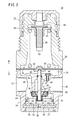
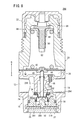
- FIG. 2 is an entire longitudinal sectional view of the pressure reducing valve shown in FIG.
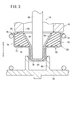
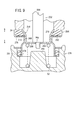
- FIG. 3 is an enlarged sectional view showing the vicinity of a valve mechanism in the pressure reducing valve of FIG.
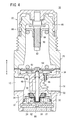
- FIG. 4 is a whole longitudinal cross-sectional view showing a state in which the primary side port and the secondary side port are in communication with each other in the pressure reducing valve shown in FIG. 2 with the valve body displaced downward.
- FIG. 5A is an enlarged cross-sectional view of the vicinity of the valve mechanism including the valve body according to the first modification, and FIG.
- FIG. 5B is an enlarged cross-sectional view of the vicinity of the valve mechanism including the valve body according to the second modification.
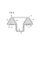
- FIG. 6 is an enlarged sectional view showing the vicinity of a valve mechanism according to a third modification.
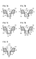
- 7A to 7E are enlarged cross-sectional views showing modifications of the connection structure between the first housing and the second housing that constitute the valve body.
- FIG. 8 is an entire longitudinal cross-sectional view of a pressure reducing valve to which a valve structure of a fluid pressure device according to a second embodiment of the present invention is applied.
- FIG. 9 is an enlarged sectional view showing the vicinity of the valve mechanism in the pressure reducing valve of FIG.
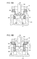
- FIG. 10A is an enlarged cross-sectional view of the vicinity of the valve mechanism including the valve body according to the fourth modification
- FIG. 10B is an enlarged cross-sectional view of the vicinity of the valve mechanism including the valve body according to the fifth modification.
- reference numeral 10 denotes a pressure reducing valve to which the valve structure of the fluid pressure device according to the first embodiment of the present invention is applied.
- the pressure reducing valve 10 is, as shown in FIGS. 1 to 4, a body 16 having a primary side port 12 and a secondary side port 14 and a flow from the primary side port 12 to the secondary side port 14. And a bonnet 20 fitted to the upper part of the body 16 and a handle 22 rotatably provided on the bonnet 20.
- the primary side port 12 and the secondary side port 14 are formed on a substantially straight line, and a communication chamber 24 is formed therebetween.
- the communication chamber 24 opens downward (in the direction of the arrow A), and a cap 26 is attached and closed at the opening portion, and a valve described later sandwiching a cover plate 27 at the upper portion of the cap 26
- a spring holder 28 for holding a valve spring 52 constituting the mechanism 18 is attached.
- An annular O-ring 30 is mounted on the outer peripheral surface of the spring holder 28 and is in contact with the inner wall surface of the communication chamber 24.
- a communication passage 32 is provided in the communication chamber 24 for connecting the primary side port 12 and the secondary side port 14, and a valve body 50 of a valve mechanism 18 described later is seated at the opening of the communication passage 32.
- An annular valve seat 34 is formed. The valve seat 34 is formed on the lower side (the direction of the arrow A) so as to face the opening of the communication chamber 24.
- a diaphragm chamber 36 is formed between the upper end portion of the body 16 and the bonnet 20, and a diaphragm 38 having a peripheral edge held between the body 16 and the bonnet 20 is disposed.
- the diaphragm 38 is formed of, for example, a thin film elastic material, and a base holder 40 is provided at the central portion thereof, and a disc-like holding plate 42 is provided on the upper surface side thereof. It is fitted to the part.
- the central portion of the diaphragm 38 is held from below by the base holder 40, and is held by the holding plate 42 within a predetermined range in the radially outward direction centering on the base holder 40.
- the central portion of the diaphragm 38 is held by the base holder 40 and the holding plate 42.
- the diaphragm 38 is bent along with the base holder 40 along the axial direction (the directions of arrows A and B) together with the base holder 40 so that the space between the diaphragm 38 and the peripheral portion is bent.
- a cylinder 44 is provided between the diaphragm chamber 36 and the communication passage 32 substantially in parallel with the axis of the body 16, and the communication passage 32 and the diaphragm are disposed through the bypass passage 46 penetrating the central portion of the cylinder 44.
- the chamber 36 is in communication.
- the valve mechanism 18 is provided inside the body 16 and is provided with a stem 48 provided displaceably along the axial direction (directions of arrows A and B) in the communication chamber 24 and a valve body connected to the lower end of the stem 48 And a valve spring 52 for biasing the valve body 50 toward the valve seat 34.
- the stem 48 is formed in an axial shape having a predetermined length along the axial direction (the directions of arrows A and B), and is displaceable in a stem hole 54 communicating with the communication passage 32 and penetrating along the axial direction of the body 16 Is inserted.
- An annular seal ring 56 is attached to the outer peripheral surface of the stem 48, and fluid leakage through the space between the stem 48 and the stem hole 54 is prevented by sliding contact with the inner peripheral surface of the stem hole 54. .
- the upper end of the stem 48 is inserted into the recess of the base holder 40 through the stem hole 54, and the lower end of the stem 48 is connected to a first housing (holding member) 58 (described later) constituting the valve body 50. .
- the valve body 50 has a first housing 58 connected to the stem 48, a second housing (casing) 60 provided on the outer peripheral side of the first housing 58, and a space between the first housing 58 and the second housing 60. And a packing (seal member) 62 provided on the
- the first and second housings 58 and 60 are formed, for example, by press-forming a thin plate material made of a metal material such as stainless steel.
- the first housing 58 extends from the open end of the bottomed cylindrical first cylindrical portion (first connecting portion) 64 and the open end of the first cylindrical portion 64 while gradually enlarging the diameter outward in the radial direction. And a tapered portion 66. Then, when the valve body 50 including the first housing 58 is provided in the communication chamber 24, the first cylindrical portion 64 is inserted into the guide hole 68 formed in the central portion of the spring holder 28.
- the guide hole 68 of the spring holder 28 is provided to displace the first cylindrical portion 64 along the axial direction (the directions of arrows A and B) so as to be displaceable. It functions as a guide mechanism that guides the valve body 50 including the cylindrical portion 64 along the axial direction (arrows A and B).
- the second housing 60 includes a bottomed cylindrical second cylindrical portion (second connecting portion) 70, a flat portion 72 extending radially outward from an open end of the second cylindrical portion 70, and the flat surface.
- the second cylindrical portion 70 is formed to be larger in diameter than the first cylindrical portion 64 of the first housing 58, and the first cylindrical portion 64 is inserted into the second cylindrical portion 70. Then, the end of the first cylindrical portion 64 and the end of the second cylindrical portion 70 may be integrally connected, for example, by welding, adhesion or the like.
- the first housing 58 and the second housing 60 are formed so that the heights along the axial direction (the directions of arrows A and B) are substantially equal.
- the lower end portion of the stem 48 is inserted into the first cylindrical portion 64 of the first housing 58, and the bottom of the first cylindrical portion 64 Abuts the wall.
- the packing 62 is formed in a ring shape, for example, from an elastic material such as rubber, and is mounted between the tapered portion 66 of the first housing 58 and the outer wall portion 74 of the second housing 60.
- the second housing 60 is in contact with the outer peripheral surface of the packing 62
- the first housing 58 is in contact with the inner peripheral surface of the packing 62.
- the packing 62 is formed in a substantially trapezoidal cross-sectional shape whose inner peripheral surface gradually reduces in diameter downward, and the inner peripheral surface is pressed radially outward by the tapered portion 66 of the first housing 58.
- the second housing 60 is fixed by being held between the second housing 60 and the outer wall 74.
- the outer circumferential surface of the packing 62 is also pressed radially inward, The inner circumferential surface abuts on the tapered portion 66 of the first housing 58.
- the tapered portion 66 prevents the packing 62 from coming off.
- the packing 62 is mounted between the first housing 58 and the second housing 60, and one end surface along the axial direction (directions of arrows A and B) is a flat portion 72 of the second housing 60.
- the other end surface is disposed to face the outside between the tapered portion 66 of the first housing 58 and the outer wall portion 74 of the second housing 60, and the other end surface is the tapered portion 66 and the outer wall portion 74. It protrudes slightly outside the end of the.
- a first seal portion 78 annularly projecting at a predetermined height along the axial direction (arrow A direction) is provided, and by abutting on the flat portion 72, the second housing 60 and The flow of fluid between the packing 62 and the packing 62 is blocked.
- a second seal portion 80 annularly projecting at a predetermined height along the axial direction (arrow B direction) is formed and seated against a valve seat 34 of the body 16 described later.
- first seal portion 78 and the second seal portion 80 are formed to project in opposite directions in the packing 62.
- the valve spring 52 is, for example, a helically wound coil spring, and is interposed between the spring holder 28 and the flange portion 76 of the second housing 60 and includes the valve body 50 including the second housing 60. It is always biased toward the valve seat 34, that is, in a direction (arrow B direction) away from the spring holder 28.
- the bonnet 20 is formed in a cylindrical shape and connected to the upper end of the body 16, and a shaft 82 rotatably provided therein, a pressure control spring 84 provided on the outer peripheral side of the shaft 82, and A holder 86 screwed to the shaft 82 is accommodated.
- the shaft 82 is formed with a flange portion 88 expanded radially outward at a substantially central portion along the axial direction, and a screw portion 90 is formed on the outer peripheral surface below the flange portion 88.
- the upper end portion of the shaft 82 protrudes from the upper portion of the bonnet 20 by a predetermined height, and is inserted into the hole portion of the handle 22 described later.
- the pressure adjustment spring 84 is, for example, a coil spring and is interposed between the holder 86 and the holding plate 42, and the elastic force of the pressure adjustment spring 84 separates the holder 86 and the holding plate 42 from each other. It is biased in the direction.
- a central portion of the holder 86 is screwed into the threaded portion 90 of the shaft 82, and is freely displaced axially along the rotation of the shaft 82. Then, the holder 86 is displaced downward along the shaft 82, whereby the pressure adjustment spring 84 is pressed downward (in the direction of arrow A). When the holder 86 is displaced upward (in the direction of the arrow B), the flange portion 88 of the shaft 82 functions as a stopper which regulates the displacement.
- the handle 22 is formed in a cylindrical shape with a bottom and is provided so as to cover the upper end of the bonnet 20, and the upper end of the shaft 82 is fitted in the center thereof. Then, when a worker (not shown) rotates the handle 22, the shaft 82 is integrally rotated to move the holder 86 along the axial direction.
- the pressure reducing valve 10 to which the valve structure according to the first embodiment of the present invention is applied is basically configured as described above, and then the assembly of the valve body 50 constituting the valve mechanism 18 A brief explanation of
- the second housing 60 is placed so that the second cylindrical portion 70 is downward, and the packing 62 is inserted into the inside from the opened upper side.
- the packing 62 is inserted such that the inner peripheral surface is expanded most and the other end surface where the second seal portion 80 is formed is upward, and the outer peripheral surface is the outer wall portion 74 of the second housing 60.
- the first seal portion 78 is inserted so as to abut on the flat portion 72 of the second housing 60.
- the first housing 58 is gripped so that the first cylindrical portion 64 is downward, inserted from above the second housing 60 into the inside of the second housing 60, and after the inside of the packing 62 is inserted.
- the first cylindrical portion 64 is inserted into the second cylindrical portion 70.
- the inner peripheral surface of the packing 62 abuts on the tapered portion 66 of the first housing 58, and the packing 62 is held between the first housing 58 and the second housing 60.
- first cylindrical portion 64 and the second cylindrical portion 70 are welded (for example, Spot welding).
- first cylindrical portion 64 and the second cylindrical portion 70 are firmly connected, and accordingly, the first housing 58 and the second housing 60 are fixed to each other in the assembled state.
- the packing 62 is sandwiched and held between the tapered portion 66 of the first housing 58 and the outer wall portion 74 of the second housing 60, and the tapered portion 66 is gradually extended upward It inclines so as to approach the part 74 side. Therefore, when the outer wall portion 74 is pressed radially inward by the pressure of the pressure fluid supplied into the communication chamber 24, the outer circumferential surface of the packing 62 is similarly pressed radially inward, and the inner circumferential surface is The packing 62 is prevented from coming off by the tapered portion 66 by abutting on the tapered portion 66 of the first housing 58.
- the packing 62 is prevented from being pulled out to the outside through the space between the tapered portion 66 and the outer wall portion 74.
- the tapered portion 66 functions as a dropout prevention means that prevents the packing 62 from falling off with respect to the first and second housings 58 and 60.
- the stem 48 is inserted into the first housing 58 from above, and the lower end portion of the stem 48 is inserted into the inside of the first cylindrical portion 64 and abuts on the bottom wall.
- valve body 50 is biased upward (in the direction of arrow B) by the elastic force of the valve spring 52, and the packing 62 abuts against the valve seat 34 in an initial closed position.
- the valve body 50 is biased upward (in the direction of arrow B) by the elastic force of the valve spring 52, and the packing 62 abuts against the valve seat 34 in an initial closed position.
- pressure fluid is supplied from a pressure fluid supply source (not shown) to the primary side port 12 through a pipe etc., and a worker (not shown) rotates the handle 22 in a predetermined direction.
- the pressure of the pressure fluid to be supplied to the fluid pressure device (not shown) connected to the line 14 via a pipe or the like is set.
- the holder 86 is displaced downward by rotating the handle 22, and the pressure adjustment spring 84 is pressed by the holder 86, so that the diaphragm 38 is moved downward (arrow (A direction) is pressed.
- the base holder 40 is lowered together with the diaphragm 38, and the stem 48 and the valve body 50 are pushed downward against the resilient force of the valve spring 52.
- the valve body 50 is separated from the valve seat 34, and the primary port 12 and the secondary port 14 communicate with each other through the communication passage 32 and the communication chamber 24.
- the pressure of the pressure fluid supplied from the secondary side port 14 to the fluid pressure device (hereinafter referred to as the secondary side pressure) is the pressure of the pressure fluid supplied from the pressure fluid source to the primary side port 12 (
- the secondary side pressure is the pressure of the pressure fluid supplied from the pressure fluid source to the primary side port 12 (
- the secondary side pressure a part of the pressure fluid flowing to the secondary side port 14 through the communication passage 32 is supplied into the diaphragm chamber 36 through the bypass passage 46. Press upwards.
- the pressing force for pressing the diaphragm 38 upward and the elastic force of the pressure adjustment spring 84 biased downward to the diaphragm 38 oppose each other, and the fluid pressure from the secondary side port 14
- the secondary pressure of the pressure fluid supplied to the device is regulated.
- the secondary pressure is lower than the set pressure previously set by the rotation of the handle 22, the supply of pressure fluid to the fluid pressure device (not shown) is continued through the secondary port 14.
- the diaphragm 38 is gradually displaced upward against the elastic force of the pressure adjustment spring 84, and the stem 48 and the valve body 50 together with the diaphragm 38.
- the flow rate of the pressure fluid flowing between the valve body 50 and the valve seat 34 decreases.
- valve body 50 When the pressure reaches a preset pressure, the valve body 50 is seated on the valve seat 34 to shut off the supply of pressure fluid from the primary port 12 to the secondary port 14 and maintain the secondary pressure. It will be done. As a result, the pressure fluid of the secondary pressure adjusted to the set pressure is supplied to the fluid pressure device connected to the secondary port 14.
- the valve body 50 constituting the valve mechanism 18 includes the first housing 58 and the second housing 60 formed of a metal material, and is provided on the outer peripheral side.
- a first housing 58 is provided inside the second housing 60, and a packing 62 made of an elastic material is provided between the second housing 60 and the first housing 58.
- the packing 62 can be reliably attached and held by the simple operation of assembling the first housing 58 and the second housing 60 in this manner, stable sealing performance by the packing 62 can be obtained. Further, since the first and second seal portions 78, 80 are provided on the end face of the packing 62, the packing 62 and the second housing 60 can be obtained by bringing the first seal portion 78 into contact with the second housing 60. The pressure fluid can be reliably prevented from flowing through the gap. As a result, in the related art in which the packing 62 is adhered to the housing, the peeling of the packing 62 which is concerned when the pressure fluid flows between the packing 62 and the housing does not occur. 62 can reliably block the flow of the pressure fluid.
- the step of applying the adhesive to the packing 62 or the housing which has been performed in the prior art, becomes unnecessary, so that the manufacturing efficiency can be improved and the adhesive It is also possible to reduce the manufacturing cost because the cost required for the above can be eliminated.
- the adhesive force is reduced and the seal member and the casing are Although the fixing may have been insufficient, in the configuration of the present invention, the limitation of the material used for the packing 62 is avoided, and for example, the desired sealing performance according to the type of pressure fluid and the pressure value is obtained. It is possible to securely fix the first housing 58 and the second housing 60 by appropriately selecting and using the packing 62 made of a material. As a result, the sealing performance of the packing 62 can be improved.
- the pressure fluid supplied into the communication chamber 24 is the first housing 58 and Entry to the first cylindrical portion 64 side through the space between the packing 62 is blocked.
- the first and second seal portions 78, 80 are provided on one end surface and the other end surface of the packing 62, and by abutting on the second housing 60 and the valve seat 34, although it is configured to shut off the flow of pressure fluid through the space between the second housing 60 and the flow of pressure fluid through the space between the body 16 and the valve body 50, the present invention is not limited to this structure.
- the second seal portion 80 in the packing 62 instead of providing the second seal portion 80 in the packing 62, as in the valve mechanism 100 according to the first modification shown in FIG. 5A, it protrudes from the end face of the valve seat 34 to the packing 62 side (arrow A direction).
- An annular first projection 102 may be provided. In this case, when the packing 62 is seated on the valve seat 34, the other end face reliably abuts against the first projection 102, so that the fluid flow through between the packing 62 and the valve seat 34 is It is surely blocked.
- the packing 62 side (arrows as shown in FIG. 5B on the flat portion 72 of the second housing 60 as in the valve mechanism 110 according to the second modification).
- the 1st projection part 102 which protruded from the end surface of the valve seat 34 may be provided.
- the first and second protrusions 102 and 114 respectively abut on one end surface and the other end surface of the packing 62, the fluid between the packing 62 and the second housing 60 and the valve seat 34 Distribution is reliably blocked.
- the second housing 60 is not limited to the case where the outer wall portion 74 is formed to be bent at a right angle to the flat portion 72 and extend upward as described above, for example, As in the second housing 120 shown in FIG. 6, the outer wall portion 122 may be inclined at a predetermined angle so as to return radially inward from the outer edge of the flat portion 72 and extend upward. Good.
- the outer wall portion 122 is inclined with respect to the plane portion 72 at an inclination angle ⁇ 2 substantially equal to the inclination angle ⁇ 1 of the taper portion 66 of the first housing 58 with respect to the plane portion 72, for example ( ⁇ 1 ⁇ ⁇ 2).
- the tapered portion 66 of the first housing 58 and the outer wall portion 122 of the second housing 120 are formed to be inclined so as to gradually approach each other.
- the packing (seal member) 126 is formed in a triangular shape in cross section that gradually tapers upward, and the tapered portion 66 of the first housing 58 abuts on the inner peripheral surface thereof, and the outer peripheral surface
- the outer wall portion 122 of the second housing 120 abuts, and the tapered portion 66 and the outer wall portion 122 securely hold and hold the same.
- valve mechanism 18 of the pressure reducing valve 10 according to the above-described first embodiment, the case where the first housing 58 and the second housing 60 are integrally connected by welding, bonding or the like has been described. It is not limited.
- annular recess 136 is provided on the outer peripheral surface of the first cylindrical portion (first connecting portion) 134 in the first housing 132, and the first cylindrical portion 134 is used as a second housing.
- the second cylindrical portion 140 After being inserted into the second cylindrical portion (second connecting portion) 140 of 138, the second cylindrical portion 140 is caulked and recessed radially inward from the outer peripheral surface side by a clamping jig (not shown).
- the first housing 132 and the second housing 138 may be connected by engaging the fastening portion 142 and the annular recess 136.
- the first cylindrical portion (first connecting portion) 154 of the first housing 152 is provided with a bulging portion 156 that bulges radially outward
- the diameter is enlarged corresponding to the bulging portion 156, and slightly larger than the outer diameter of the bulging portion 156
- a fitting portion 162 having an inner circumferential diameter only as small as that of the small diameter may be provided, and the bulging portion 156 may be inserted into the second cylindrical portion 160 and fitted to the fitting portion 162.
- first housing 152 and the second housing 158 may be integrally connected by press-fitting the first cylindrical portion 154 into the second cylindrical portion 160.
- an external thread 176 is engraved on the outer peripheral surface of the first cylindrical portion (first connecting portion) 174 in the first housing 172, while the second housing 178
- a female screw 182 is engraved on the inner peripheral surface of the cylindrical portion (second connecting portion) 180, and the first cylindrical portion 174 is screwed to the inner peripheral surface of the second cylindrical portion 180 to thereby form the first housing.
- the second housing 178 and the second housing 178 may be integrally connected.
- the first cylindrical portion (first connecting portion) 194 of the first housing 192 is provided with a plurality of radially tiltable lips 196 near its tip end portion.
- the projection 198 is provided on the outer peripheral surface of the lip 196 so as to protrude radially outward, and the first cylindrical portion 194 is inserted into the second cylindrical portion (second connecting portion) 202 of the second housing 200,
- the projecting portion 198 is engaged with the radially outwardly expanded engaging portion 204 in the second cylindrical portion 202, and the elastic force of the lip 196 holds the engaged state. That is, the first housing 192 and the second housing 200 may be integrally fixed via the plurality of lips 196.
- the lower end portion of the tapered portion 66 of the first housing 212 is engaged with the annular groove 216 provided on the outer peripheral surface of the stem 214 and the second housing 218 Similarly, by engaging the radially inward projecting engagement portion 222 with the annular groove 216, the first and second housings 212 and 218 are combined with the stem 214. You may make it connect with respect to each other.
- relative displacement is regulated along the axial direction of the first housing 132, 152, 172, 192, 212 and the second housing 138, 158, 178, 200, 218, and integrally displaced. As long as it is a connectable structure.
- FIG. 8 a pressure reducing valve 250 to which the valve structure of the fluid pressure device according to the second embodiment is applied is shown in FIG. 8 and FIG.
- the same referential mark is attached
- valve body 254 constituting the valve mechanism 252 is provided on the outer peripheral side of the first housing 258 connected to the lower end portion of the stem 256, and the first housing 258. And a packing (seal member) 262 is held between the first housing 258 and the second housing 260.
- the first housing 258 is formed to have a U-shaped cross section, the bottom of which is provided downward, and the center of the bottom is formed with a hole 264 into which the lower end of the stem 256 is inserted.
- a plurality of communication holes 266 are formed spaced apart radially outward from the hole 264.
- the first housing 258 includes an outer wall 268 bent at a right angle from the outer edge of the bottom, and a tapered portion 270 inclined so as to radially expand outward from the upper end of the outer wall 268.
- the second housing 260 includes a base portion 272 fitted to the outer wall portion 268 of the first housing 258, and a skirt formed at a lower portion of the base portion 272 and extending radially outward and extending downward It comprises a portion 274 and a packing holding portion 276 which is formed on the upper portion of the base portion 272 and extends horizontally outward in the radial direction and then bent at a right angle to extend upward.
- the second housing 260 is integrally connected to the first housing 258 through the base portion 272, and an O-ring 261 is provided between the outer peripheral surface of the skirt portion 274 and the communication chamber 24 of the body 16.
- an annular packing 262 is attached to the packing holding portion 276 and held between the packing holding portion 276 and the tapered portion 270 of the first housing 258.
- the spring holder 278 is attached to the lower portion of the body, and a valve guide 280 projecting upward is provided at the central portion thereof. Then, the valve spring 52 is inserted through the outer peripheral side of the valve guide 280 and interposed between the valve spring and the bottom of the second housing 260.
- valve mechanism 252 which comprises the pressure-reduction valve 250 which concerns on 2nd Embodiment is not limited to the structure mentioned above,
- the 2nd housing 292 And an O-ring 261 is attached to the annular recess 294, and the upper end of the second housing 292 is bent at a predetermined angle in the radially inward direction, and a cross section is formed.
- the triangular packing (seal member) 296 may be held between the first housing 258 and the packing.
- a flange 304 capable of holding the O-ring 261 is provided at the lower end of the second housing 302, and the outer wall 308 of the first housing 306 and the taper 310
- a stepped portion 312 is provided at the boundary portion and slightly outward in the radial direction from the end of the outer wall portion 308, and the stepped portion 312 is engaged with the packing holding portion 314 of the second housing 302. You may do so.
- a cylindrical pressing member 361 is provided on the outer peripheral side of the base portion 272 to prevent the O-ring 261 from being separated upward from the collar portion 304. Thereby, when assembling the first housing 306 and the second housing 302, it is possible to easily and reliably position each other.
- the second housing 302 is configured to hold the O-ring 261, there is no need to provide an annular groove for mounting the O-ring 261 on the spring holder 278 side, and the processing cost for the spring holder 278 is reduced. be able to.
- valve mechanism 18, 100, 110, 252, 290, 300 is applied to the pressure reducing valve 10, 250 which is a fluid pressure device
- the invention is not limited to this. Instead, for example, it may be used for an on-off valve capable of switching the fluid flow state by closing / opening the valve body.
- valve structure of the fluid pressure device according to the present invention is not limited to the above-described embodiment, and it goes without saying that various configurations can be adopted without departing from the scope of the present invention.
Abstract
Description
前記ボディの内部に変位自在に設けられるケーシングと、
前記ケーシングの内部に設けられ、前記ボディに形成された弁座に着座する環状のシール部材と、
前記ケーシングの内部に設けられ、前記シール部材を該ケーシングとの間に保持する保持部材と、
を備え、
前記ケーシングと前記保持部材とが一体的に装着されると共に、前記ケーシングの中央部に連接されるステムを介して該ケーシング及びシール部材が前記弁座に対して接近・離間する方向に変位することを特徴とする。 The present invention is a valve structure of a fluid pressure device having a port for supplying and discharging pressure fluid, and capable of adjusting the flow state of the pressure fluid flowing in the body through the port,
A casing displaceably provided inside the body;
An annular seal member provided inside the casing and seated on a valve seat formed on the body;
A holding member provided inside the casing for holding the seal member between the casing and the holding member;
Equipped with
The casing and the holding member are integrally mounted, and the casing and the seal member are displaced in a direction toward and away from the valve seat through a stem connected to a central portion of the casing. It is characterized by
Claims (11)
- 圧力流体の供給・排出されるポート(12、14)を有し、前記ポート(12、14)を介してボディ(16)内に流通する前記圧力流体の流通状態を調整可能な流体圧機器の弁構造であって、
前記ボディ(16)の内部に変位自在に設けられるケーシング(60)と、
前記ケーシング(60)の内部に設けられ、前記ボディ(16)に形成された弁座(34)に着座する環状のシール部材(62)と、
前記ケーシング(60)の内部に設けられ、前記シール部材(62)を該ケーシング(60)との間に保持する保持部材(58)と、
を備え、
前記ケーシング(60)と前記保持部材(58)とが一体的に装着されると共に、前記ケーシング(60)の中央部に連接されるステム(48)を介して該ケーシング(60)及びシール部材(62)が前記弁座(34)に対して接近・離間する方向に変位することを特徴とする流体圧機器の弁構造。 A fluid pressure device having ports (12, 14) for supplying and discharging pressure fluid, and capable of adjusting the flow state of the pressure fluid flowing in the body (16) via the ports (12, 14). Valve structure,
A casing (60) provided displaceably inside the body (16);
An annular seal member (62) provided inside the casing (60) and seated on a valve seat (34) formed on the body (16);
A holding member (58) provided inside the casing (60) and holding the seal member (62) between the casing (60);
Equipped with
The casing (60) and the seal member (60) are mounted via a stem (48) integrally attached to the casing (60) and the holding member (58) and connected to the central portion of the casing (60). 62) A valve structure of fluid pressure equipment characterized in that it is displaced in a direction toward and away from the valve seat (34). - 請求項1記載の弁構造において、
前記ケーシング(60)には、前記シール部材(62)を保持可能なシール保持部(74)を備え、前記シール保持部(74)の内周側に前記保持部材(58)が挿入されると共に、前記保持部材(58)には、該ケーシング(60)に対する挿入方向とは反対方向に向かって徐々に拡径するテーパ部(66)を備え、前記テーパ部(66)と前記シール保持部(74)との間に前記シール部材(62)が挟持されることを特徴とする流体圧機器の弁構造。 In the valve structure according to claim 1,
The casing (60) includes a seal holding portion (74) capable of holding the seal member (62), and the holding member (58) is inserted on the inner peripheral side of the seal holding portion (74). The holding member (58) includes a tapered portion (66) whose diameter gradually increases in the direction opposite to the insertion direction with respect to the casing (60), the tapered portion (66) and the seal holding portion ( 74) The valve structure of the fluid pressure device, wherein the seal member (62) is sandwiched between - 請求項2記載の弁構造において、
前記保持部材(58)には、第1連結部(64、134、154、174、194)が設けられ、前記ボディ(16)の内部において、前記シール保持部(74)が前記弁座(34)側となるように配置され、前記第1連結部(64)が、前記ケーシング(60)の第2連結部(70、140、160、180、202)と連結されることを特徴とする流体圧機器の弁構造。 In the valve structure according to claim 2,
The holding member (58) is provided with a first connecting portion (64, 134, 154, 174, 194), and the seal holding portion (74) is provided on the valve seat (34) inside the body (16). A fluid, wherein the first connection portion (64) is connected to a second connection portion (70, 140, 160, 180, 202) of the casing (60). Valve structure of pressure equipment. - 請求項3記載の弁構造において、
前記シール保持部(74)には、前記シール部材(62)の外周側に設けられた外壁部(122)を有し、前記外壁部(122)が、前記テーパ部(66)に徐々に接近するように半径内方向に縮径するように傾斜して形成されることを特徴とする流体圧機器の弁構造。 In the valve structure according to claim 3,
The seal holding portion (74) has an outer wall portion (122) provided on the outer peripheral side of the seal member (62), and the outer wall portion (122) gradually approaches the taper portion (66) The valve structure of the fluid pressure device is formed to be inclined so as to reduce the diameter in the radially inward direction. - 請求項1記載の弁構造において、
前記シール部材(62)には、前記ケーシング(60)に臨む一側面及び前記弁座(34)に臨む他側面の少なくともいずれか一方に、前記一側面及び/又は前記他側面から突出したシール部(78、80)を備えることを特徴とする流体圧機器の弁構造。 In the valve structure according to claim 1,
The seal member (62) has a seal portion projecting from the one side surface and / or the other side surface on at least one of the one side surface facing the casing (60) and the other side surface facing the valve seat (34) (78, 80) The valve structure of the fluid pressure apparatus characterized by the above-mentioned. - 請求項1記載の弁構造において、
前記シール部材(62)に臨む前記ケーシング(60)の側面及び前記弁座(34)の少なくともいずれか一方には、前記シール部材(62)側に向かって突出した突起部(102、114)を備えることを特徴とする流体圧機器の弁構造。 In the valve structure according to claim 1,
At least one of the side surface of the casing (60) facing the seal member (62) and the valve seat (34) has a projection (102, 114) protruding toward the seal member (62). Valve structure of fluid pressure equipment characterized by having. - 請求項3記載の弁構造において、
前記第1連結部(64)は、前記第2連結部(70)に対して溶接又は接着されることを特徴とする流体圧機器の弁構造。 In the valve structure according to claim 3,
The valve structure of a fluid pressure device, wherein the first connection portion (64) is welded or adhered to the second connection portion (70). - 請求項3記載の弁構造において、
前記第1連結部(154)は、前記第2連結部(160)の内部に圧入されることを特徴とする流体圧機器の弁構造。 In the valve structure according to claim 3,
The valve structure of a fluid pressure device, wherein the first connection portion (154) is pressed into the inside of the second connection portion (160). - 請求項3記載の弁構造において、
前記第1連結部(174)は、前記第2連結部(180)に対して螺合されることを特徴とする流体圧機器の弁構造。 In the valve structure according to claim 3,
The valve structure of a fluid pressure device, wherein the first connection portion (174) is screwed to the second connection portion (180). - 請求項3記載の弁構造において、
前記第1連結部(134)は、前記第2連結部(140)に対して加締められることを特徴とする流体圧機器の弁構造。 In the valve structure according to claim 3,
The valve structure of a fluid pressure device, wherein the first connection portion (134) is crimped to the second connection portion (140). - 請求項3記載の弁構造において、
前記第1連結部(194)は、半径外方向に突出した突起部(198)を備え、前記突起部(198)が前記第2連結部(202)の係合部(204)に対して係合されることを特徴とする流体圧機器の弁構造。 In the valve structure according to claim 3,
The first connection portion (194) includes a protrusion (198) protruding radially outward, and the protrusion (198) engages with the engagement portion (204) of the second connection portion (202). The valve structure of the fluid pressure device characterized in that it is combined.
Priority Applications (6)
| Application Number | Priority Date | Filing Date | Title |
|---|---|---|---|
| US13/581,508 US9133942B2 (en) | 2010-03-16 | 2010-09-16 | Valve structure for fluid pressure device |
| CN201080065450.9A CN102803800B (en) | 2010-03-16 | 2010-09-16 | Valve structure for fluid pressure device |
| KR1020127022438A KR101402866B1 (en) | 2010-03-16 | 2010-09-16 | Valve structure for fluid pressure device |
| RU2012139311/06A RU2516059C2 (en) | 2010-03-16 | 2010-09-16 | Design of valve for hydraulic or pneumatic drive |
| BR112012023386-6A BR112012023386B1 (en) | 2010-03-16 | 2010-09-16 | valve structure for fluid pressure device |
| DE112010005393.6T DE112010005393B4 (en) | 2010-03-16 | 2010-09-16 | Valve structure for fluid pressure device |
Applications Claiming Priority (2)
| Application Number | Priority Date | Filing Date | Title |
|---|---|---|---|
| JP2010059403A JP5392499B2 (en) | 2010-03-16 | 2010-03-16 | Valve structure of fluid pressure equipment |
| JP2010-059403 | 2010-03-16 |
Publications (1)
| Publication Number | Publication Date |
|---|---|
| WO2011114553A1 true WO2011114553A1 (en) | 2011-09-22 |
Family
ID=44648674
Family Applications (1)
| Application Number | Title | Priority Date | Filing Date |
|---|---|---|---|
| PCT/JP2010/066035 WO2011114553A1 (en) | 2010-03-16 | 2010-09-16 | Valve structure for fluid pressure device |
Country Status (9)
| Country | Link |
|---|---|
| US (1) | US9133942B2 (en) |
| JP (1) | JP5392499B2 (en) |
| KR (1) | KR101402866B1 (en) |
| CN (1) | CN102803800B (en) |
| BR (1) | BR112012023386B1 (en) |
| DE (1) | DE112010005393B4 (en) |
| RU (1) | RU2516059C2 (en) |
| TW (1) | TWI410575B (en) |
| WO (1) | WO2011114553A1 (en) |
Cited By (1)
| Publication number | Priority date | Publication date | Assignee | Title |
|---|---|---|---|---|
| JP2013161382A (en) * | 2012-02-08 | 2013-08-19 | Hitachi Appliances Inc | Pressure-reducing valve |
Families Citing this family (12)
| Publication number | Priority date | Publication date | Assignee | Title |
|---|---|---|---|---|
| JP5881217B2 (en) * | 2013-09-24 | 2016-03-09 | Toto株式会社 | Pressure reducing valve with dust biting release mechanism |
| US9360126B2 (en) | 2014-04-29 | 2016-06-07 | National Synchrotron Radiation Research Center | Relief valve assembly with anti-frozen shielding hat |
| FR3034162B1 (en) * | 2015-03-24 | 2018-09-21 | Vernet | THERMOSTATIC DEVICE FOR CONTROLLING CIRCULATION OF A FLUID, AND THERMOSTATIC VALVE COMPRISING SUCH A DEVICE |
| JP6228152B2 (en) * | 2015-04-01 | 2017-11-08 | Ckd株式会社 | Manual valve |
| US20180306331A1 (en) * | 2015-10-12 | 2018-10-25 | Tescom Corporation | Regulator Seal Assembly |
| FR3044782B1 (en) | 2015-12-07 | 2018-01-12 | Vernet | THERMOSTATIC MONOCOMMANDE CARTRIDGE AND MIXER FAUCET WITH SUCH A CARTRIDGE |
| FR3050510B1 (en) | 2016-04-26 | 2018-09-21 | Vernet | MIXING UNIT AND MIXER TAP COMPRISING SUCH A MIXING UNIT |
| FR3050512B1 (en) | 2016-04-26 | 2018-09-28 | Vernet | MIXING UNIT AND MIXER TAP COMPRISING SUCH A MIXING UNIT |
| FR3054282B1 (en) | 2016-07-21 | 2018-08-31 | Vernet | MIXING UNIT AND MIXER TAP COMPRISING SUCH A MIXING UNIT |
| JP1620715S (en) * | 2017-03-28 | 2018-12-17 | ||
| DE102017008556A1 (en) * | 2017-09-12 | 2019-03-14 | Wabco Gmbh | Overflow valve and compressed air device for motor vehicles |
| CN112128432B (en) * | 2020-10-23 | 2022-04-26 | 重庆磐恒阀门有限公司 | Pressure relief electromagnetic valve for toxic gas pipeline |
Citations (6)
| Publication number | Priority date | Publication date | Assignee | Title |
|---|---|---|---|---|
| JPS5074078A (en) * | 1973-11-06 | 1975-06-18 | ||
| JPS578949U (en) * | 1980-06-16 | 1982-01-18 | ||
| JPS59226771A (en) * | 1983-06-06 | 1984-12-19 | ジゼバ・ベネツト・リミテイド | Valve member |
| JPS6396367A (en) * | 1986-10-14 | 1988-04-27 | Hitachi Metals Ltd | Digital valve |
| JPH072742U (en) * | 1993-06-04 | 1995-01-17 | パロマ工業株式会社 | Gas valve |
| JPH1078166A (en) * | 1996-09-03 | 1998-03-24 | Com:Kk | Vacuum valve |
Family Cites Families (18)
| Publication number | Priority date | Publication date | Assignee | Title |
|---|---|---|---|---|
| CH286965A (en) | 1949-03-31 | 1952-11-15 | Erb Karl | Safety valve on containers that contain a pressurized fluid. |
| US2695032A (en) | 1951-10-31 | 1954-11-23 | Mcdonnell & Miller Inc | Pressure relief valve |
| US2845945A (en) * | 1956-12-06 | 1958-08-05 | Altair Inc | Sealing elements |
| US3248056A (en) * | 1963-10-18 | 1966-04-26 | Dole Valve Co | Resiliently seated fluid control valve |
| US3877480A (en) * | 1971-03-17 | 1975-04-15 | Dover Corp | Nozzle valve assembly |
| JPS5584702U (en) * | 1978-11-30 | 1980-06-11 | ||
| JPS578949A (en) | 1980-06-19 | 1982-01-18 | Toshiba Corp | Head mechanism |
| US4518329A (en) | 1984-03-30 | 1985-05-21 | Weaver Joe T | Wear resistant pump valve |
| US4671490A (en) * | 1986-05-16 | 1987-06-09 | Nupro Co. | Diaphragm valve |
| US4688757A (en) * | 1986-08-11 | 1987-08-25 | Dresser Industries, Inc. | Soft seat Y pattern globe valve |
| US4848729A (en) * | 1988-02-01 | 1989-07-18 | Dresser Industries, Inc. | Valve seal |
| CN2052095U (en) * | 1989-06-14 | 1990-01-31 | 上海东风机器厂 | Pressure-reducing valve with big overflow |
| RU2063573C1 (en) * | 1992-06-08 | 1996-07-10 | Электромеханический завод "Авангард" | Solenoid valve |
| JPH072742A (en) | 1993-04-21 | 1995-01-06 | Wako Pure Chem Ind Ltd | New production method of 4-amino-3-methyl-n-ethyl-n-(beta-hydroxyethyl)aniline sulfuric acid salt |
| JP3796006B2 (en) * | 1997-05-27 | 2006-07-12 | Smc株式会社 | Valve seal mechanism |
| US20050023496A1 (en) * | 2003-07-31 | 2005-02-03 | Foster Joseph E. | Deformed o-ring face seal for pneumatic valves |
| EP1798456A1 (en) * | 2004-07-29 | 2007-06-20 | Miura Co., Ltd. | Cutoff valve |
| JP4214130B2 (en) | 2005-05-27 | 2009-01-28 | 株式会社アイビーエスジャパン | Seal structure of on-off valve with poppet valve body |
-
2010
- 2010-03-16 JP JP2010059403A patent/JP5392499B2/en active Active
- 2010-09-16 KR KR1020127022438A patent/KR101402866B1/en active IP Right Grant
- 2010-09-16 RU RU2012139311/06A patent/RU2516059C2/en not_active IP Right Cessation
- 2010-09-16 US US13/581,508 patent/US9133942B2/en active Active
- 2010-09-16 WO PCT/JP2010/066035 patent/WO2011114553A1/en active Application Filing
- 2010-09-16 BR BR112012023386-6A patent/BR112012023386B1/en active IP Right Grant
- 2010-09-16 DE DE112010005393.6T patent/DE112010005393B4/en active Active
- 2010-09-16 CN CN201080065450.9A patent/CN102803800B/en not_active Expired - Fee Related
- 2010-09-28 TW TW99132733A patent/TWI410575B/en not_active IP Right Cessation
Patent Citations (6)
| Publication number | Priority date | Publication date | Assignee | Title |
|---|---|---|---|---|
| JPS5074078A (en) * | 1973-11-06 | 1975-06-18 | ||
| JPS578949U (en) * | 1980-06-16 | 1982-01-18 | ||
| JPS59226771A (en) * | 1983-06-06 | 1984-12-19 | ジゼバ・ベネツト・リミテイド | Valve member |
| JPS6396367A (en) * | 1986-10-14 | 1988-04-27 | Hitachi Metals Ltd | Digital valve |
| JPH072742U (en) * | 1993-06-04 | 1995-01-17 | パロマ工業株式会社 | Gas valve |
| JPH1078166A (en) * | 1996-09-03 | 1998-03-24 | Com:Kk | Vacuum valve |
Cited By (1)
| Publication number | Priority date | Publication date | Assignee | Title |
|---|---|---|---|---|
| JP2013161382A (en) * | 2012-02-08 | 2013-08-19 | Hitachi Appliances Inc | Pressure-reducing valve |
Also Published As
| Publication number | Publication date |
|---|---|
| TW201132880A (en) | 2011-10-01 |
| BR112012023386B1 (en) | 2020-12-08 |
| TWI410575B (en) | 2013-10-01 |
| BR112012023386A2 (en) | 2016-05-31 |
| DE112010005393T5 (en) | 2013-01-03 |
| JP5392499B2 (en) | 2014-01-22 |
| JP2011192159A (en) | 2011-09-29 |
| KR20120129930A (en) | 2012-11-28 |
| RU2012139311A (en) | 2014-03-20 |
| KR101402866B1 (en) | 2014-06-03 |
| RU2516059C2 (en) | 2014-05-20 |
| CN102803800B (en) | 2014-12-10 |
| US20120325339A1 (en) | 2012-12-27 |
| DE112010005393B4 (en) | 2022-10-27 |
| CN102803800A (en) | 2012-11-28 |
| US9133942B2 (en) | 2015-09-15 |
Similar Documents
| Publication | Publication Date | Title |
|---|---|---|
| WO2011114553A1 (en) | Valve structure for fluid pressure device | |
| JP5512391B2 (en) | Valve device | |
| JP3861206B2 (en) | Fluid controller | |
| KR20140012739A (en) | Internal pilot type pressure regulator | |
| US20240019034A1 (en) | Valves with integrated orifice restrictions | |
| CN107965596B (en) | Pressure reducing valve | |
| JP2018031620A (en) | Sensor installation structure | |
| CN111936775A (en) | Diaphragm valve | |
| US11808367B2 (en) | Valve, device for regulating the pressure of a flow medium using the valve, and device for securing the valve in a transmission component | |
| US6869062B2 (en) | Valve for discharging fluid from a tank | |
| JP4641955B2 (en) | Gas governor | |
| CN110553070A (en) | Dynamic balance two-way valve | |
| JP4549981B2 (en) | Fluid control equipment | |
| US11859733B2 (en) | Valve device, fluid control device, and manufacturing method of valve device | |
| JP5970426B2 (en) | Pressure operating valve and setting method of set pressure in pressure operating valve | |
| TWI820791B (en) | Valve device | |
| JP5022971B2 (en) | Pressure regulator | |
| JP5659065B2 (en) | External adjustment type constant flow valve | |
| CN112673204A (en) | Valve, method for replacing valve element unit of valve, and method for assembling valve |
Legal Events
| Date | Code | Title | Description |
|---|---|---|---|
| WWE | Wipo information: entry into national phase |
Ref document number: 201080065450.9 Country of ref document: CN |
|
| 121 | Ep: the epo has been informed by wipo that ep was designated in this application |
Ref document number: 10847961 Country of ref document: EP Kind code of ref document: A1 |
|
| ENP | Entry into the national phase |
Ref document number: 20127022438 Country of ref document: KR Kind code of ref document: A |
|
| WWE | Wipo information: entry into national phase |
Ref document number: 13581508 Country of ref document: US |
|
| WWE | Wipo information: entry into national phase |
Ref document number: 7784/CHENP/2012 Country of ref document: IN |
|
| WWE | Wipo information: entry into national phase |
Ref document number: 2012139311 Country of ref document: RU |
|
| WWE | Wipo information: entry into national phase |
Ref document number: 1201004699 Country of ref document: TH |
|
| WWE | Wipo information: entry into national phase |
Ref document number: 1120100053936 Country of ref document: DE Ref document number: 112010005393 Country of ref document: DE |
|
| 122 | Ep: pct application non-entry in european phase |
Ref document number: 10847961 Country of ref document: EP Kind code of ref document: A1 |
|
| REG | Reference to national code |
Ref country code: BR Ref legal event code: B01A Ref document number: 112012023386 Country of ref document: BR |
|
| ENP | Entry into the national phase |
Ref document number: 112012023386 Country of ref document: BR Kind code of ref document: A2 Effective date: 20120917 |