JP5659065B2 - External adjustment type constant flow valve - Google Patents
External adjustment type constant flow valve Download PDFInfo
- Publication number
- JP5659065B2 JP5659065B2 JP2011078636A JP2011078636A JP5659065B2 JP 5659065 B2 JP5659065 B2 JP 5659065B2 JP 2011078636 A JP2011078636 A JP 2011078636A JP 2011078636 A JP2011078636 A JP 2011078636A JP 5659065 B2 JP5659065 B2 JP 5659065B2
- Authority
- JP
- Japan
- Prior art keywords
- connection
- constant flow
- flow valve
- pipe
- adjustment
- Prior art date
- Legal status (The legal status is an assumption and is not a legal conclusion. Google has not performed a legal analysis and makes no representation as to the accuracy of the status listed.)
- Active
Links
- 239000012530 fluid Substances 0.000 claims description 38
- 238000007789 sealing Methods 0.000 claims description 9
- 238000004891 communication Methods 0.000 claims description 5
- 230000002093 peripheral effect Effects 0.000 description 10
- 238000000034 method Methods 0.000 description 2
- 238000010586 diagram Methods 0.000 description 1
- 238000012986 modification Methods 0.000 description 1
- 230000004048 modification Effects 0.000 description 1
- XLYOFNOQVPJJNP-UHFFFAOYSA-N water Substances O XLYOFNOQVPJJNP-UHFFFAOYSA-N 0.000 description 1
Images

Landscapes
- Safety Valves (AREA)
Description
本発明は、二つの配管を連通接続し、一方の配管を流れる流体と他方の配管を流れる流体との圧力差の大きさに拘わらず流体の通過流量をほぼ一定に保つとともに、流体の設定通過流量を外部から調節可能な外部調節式定流量弁に関する。 In the present invention, two pipes are connected in communication, the flow rate of the fluid is kept substantially constant regardless of the pressure difference between the fluid flowing in one pipe and the fluid flowing in the other pipe, and the set passage of the fluid is maintained. The present invention relates to an externally adjustable constant flow valve capable of adjusting the flow rate from the outside.
従来、種々の分野において、二つの配管を連通接続し、一方の配管を流れる流体と他方の配管を流れる流体との圧力差の大きさに拘わらず流体の通過流量をほぼ一定に保つ定流量弁が用いられている。 Conventionally, in various fields, two pipes are connected in communication, and a constant flow valve that keeps the flow rate of the fluid almost constant regardless of the pressure difference between the fluid flowing in one pipe and the fluid flowing in the other pipe. Is used.
この種の定流量弁の一例として、下記特許文献1には、筒状に成形され且つ所望流量に調節するための通水孔が一つ以上所定の位置及び所定の口径で貫通されている定流量エレメントを弁の内部に配置し、流体の圧力差の大きさに拘わらず通過流量を一定に保つ内部調節式の定流量弁が提案されている。この定流量弁は、複数の定流量エレメントをケース体の装着孔に径外方から差し込んだ後に装着孔を蓋体で覆うことにより組み立てられ、この定流量弁を継手体に装着し、定流量弁に形成されている雄ねじ部と継手体に形成されている雌ねじ部を配管にねじ係合させることで、配管の途中に取り付けられる。
As an example of this type of constant flow valve, the following
この定流量弁では、流体の設定通過流量を調節しようとするときには、先ず、定流量弁を流れる流体を止めてから定流量弁及び継手体を配管から取り外し、取り外した定流量弁の設定通過流量の変更を行った後、定流量弁を継手体とともに再び配管に取り付けるという、複雑で手間のかかる作業を強いられる。設定通過流量を再調節する必要な場合には、上記の調節作業を再度繰り返す必要があり、作業性が極めて悪いという問題点がある。 With this constant flow valve, when trying to adjust the set flow rate of fluid, first stop the fluid flowing through the constant flow valve, then remove the constant flow valve and joint from the pipe, and remove the set flow rate of the removed constant flow valve. After making this change, the complicated and time-consuming work of attaching the constant flow valve together with the joint to the pipe is forced. When it is necessary to readjust the set passage flow rate, it is necessary to repeat the above adjustment work again, and there is a problem that workability is extremely poor.
本発明は上記事情に鑑みてなされたものであって、配管が接続された状態で流体の設定通過流量の変更を外部からの簡単な操作で行えるようにした外部調節式定流量弁を提供することにある。 The present invention has been made in view of the above circumstances, and provides an externally adjustable constant flow valve capable of changing a set passage flow rate of a fluid with a simple operation from the outside while a pipe is connected. There is.
上記の課題を解決するため、本発明は、
二つの配管を連通接続し、一方の配管を流れる流体と他方の配管を流れる流体との圧力差の大きさに拘わらず前記流体の通過流量をほぼ一定に保つとともに、前記流体の設定通過流量を外部から調節可能な外部調節式定流量弁であって、
前記一方の配管に接続される第1接続部材と、
前記他方の配管に接続される第2接続部材と、
前記第1接続部材又は第2接続部材に対して移動可能に装着された調節部材と、
前記調節部材との間に前記流体を通過させるクリアランスを形成するとともに、前記圧力差に応じて前記クリアランスを変更するように移動する弁部材と、
前記第1接続部材と前記第2接続部材とを連結するとともに、前記第1及び第2接続部材にそれぞれ配管に接続された状態で前記第1接続部材と前記第2接続部材との連結を解除することにより、前記調節部材の前記弁部材に対する位置が調節可能となるように形成された連結部材とを備えることを特徴としている。
In order to solve the above problems, the present invention provides:
Two pipes are connected in communication, the flow rate of the fluid is kept almost constant regardless of the pressure difference between the fluid flowing in one pipe and the fluid flowing in the other pipe, and the set passing flow rate of the fluid is An externally adjustable constant flow valve that can be adjusted from the outside.
A first connecting member connected to the one pipe;
A second connecting member connected to the other pipe;
An adjustment member movably attached to the first connection member or the second connection member;
A valve member that forms a clearance for allowing the fluid to pass between the adjustment member and moves so as to change the clearance according to the pressure difference;
The first connection member and the second connection member are connected, and the connection between the first connection member and the second connection member is released in a state where the first connection member and the second connection member are connected to the pipes, respectively. And a connecting member formed so that the position of the adjusting member relative to the valve member can be adjusted.
この外部調節式定流量弁によれば、第1及び第2接続部材にそれぞれ配管が接続された状態で連結部材による第1接続部材と第2接続部材との連結を解除することにより、調節部材の弁部材に対する位置を調節することができるので、調節部材と弁部材との間に設定されているクリアランスが変更可能である。これによって、配管を取り外すことなく流体の設定通過流量を簡単な操作で変更することができる。また、二つの配管を接続するジョイントの役目も兼ねるので、接続部品の点数と接続作業の手間が低減する。 According to this external adjustment type constant flow valve, the adjustment member is released by releasing the connection between the first connection member and the second connection member by the connection member in a state where the pipes are connected to the first and second connection members, respectively. Since the position of the valve member relative to the valve member can be adjusted, the clearance set between the adjustment member and the valve member can be changed. Thereby, the set passage flow rate of the fluid can be changed by a simple operation without removing the pipe. Moreover, since it also serves as a joint for connecting two pipes, the number of connecting parts and the labor of connecting work are reduced.
この外部調節式定流量弁は、第1及び第2接続部材が筒状であるとともに配管が同軸状に接続されるように形成され、前記調節部材が筒状に形成され、前記第1及び第2接続部材、前記調節部材が同軸状に配置されるとともに、これらの内部にストレートな流路が形成されるように構成することで、流体の圧力損失が低減するので好ましい。 The external adjustment type constant flow valve is formed so that the first and second connecting members are cylindrical and the pipes are coaxially connected, the adjusting member is formed in a cylindrical shape, and the first and second It is preferable that the two connecting members and the adjusting member are arranged coaxially and that a straight flow path is formed inside these members, because the pressure loss of the fluid is reduced.
また、具体的には、前記調節部材が、前記第1又は第2接続部材に対して軸方向に移動可能に螺着されているとともに前記調節部材を回転させるための回転操作部を備えており、前記連結部材による前記第1及び第2接続部の連結を解除した状態で前記第1接続部と前記第2接続部との間に前記回転操作部が露出するように構成することができる。
この場合、前記回転操作部は、前記調節部材を回転させるための工具が係合するように構成することで、設定通過流量の調節がさらに容易になるので好ましい。
また、前記連結部材による前記第1及び第2接続部の連結を解除した状態で、前記第1及び第2接続部と前記調節部材との間をシールするシール手段を備えることで、流体が流れたままの状態で設定通過流量を調節できるので、好ましい。
Specifically, the adjustment member is screwed to the first or second connection member so as to be movable in the axial direction, and includes a rotation operation unit for rotating the adjustment member. The rotation operation part may be exposed between the first connection part and the second connection part in a state where the connection of the first and second connection parts by the connection member is released.
In this case, it is preferable that the rotation operation unit is configured so that a tool for rotating the adjustment member is engaged, so that the adjustment of the set passage flow rate is further facilitated.
In addition, a fluid flows by providing sealing means for sealing between the first and second connection portions and the adjustment member in a state where the connection of the first and second connection portions by the connection member is released. This is preferable because the set passage flow rate can be adjusted in the state where it remains.
本発明によれば、配管が接続された状態で流体の設定通過流量の変更を外部からの簡単な操作で行うことができるので、設定通過流量調節の手間が低減する。 According to the present invention, the setting passage flow rate of the fluid can be changed with a simple operation from the outside in a state where the pipe is connected.
以下、添付した図面に基づいて、この発明による外部調節式定流量弁(以下、「定流量弁」と略す。)の実施例を説明する。 Embodiments of an externally adjustable constant flow valve (hereinafter abbreviated as “constant flow valve”) according to the present invention will be described below with reference to the accompanying drawings.
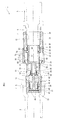
図1に示す定流量弁1は、流体が流れる一方の配管2と、その軸線方向に同軸状に対向配置され、配管2に接続されるべき他方の配管3との間に介装され、両配管2、3を連通接続する。配管2の定流量弁1側の端部4は拡大されていて、且つその内側には後述する第1接続部材11との接続用の雌ねじ5が形成されている。配管3の定流量弁1側の端部6は小径に形成されていて、且つその外側には後述する第2接続部材12との接続用の雄ねじ7が形成されている。
A
定流量弁1は、一方の配管2に接続される筒状の第1接続部材11と、他方の配管3に接続される筒状の第2接続部材12と、第1接続部材11に軸方向に摺動自在に内装された弁部材13と、第1接続部材11に軸方向に移動自在に螺着された筒状の調節部材14と、第1接続部材11と第2接続部材12とを連結する筒状の連結部材15とを備えている。第1接続部材11及び第2接続部材12、調節部材14は同軸状に配置されており、定流量弁1の内部の流体経路を全体的にストレートに形成している。この構造により、定流量弁1を流れる流体の圧力損失を可及的に小さくすることができる。
The
第1接続部材11は、概して円筒状の部材であって、一方の端部20(配管2側)の外周には雄ねじ21が形成されている。雄ねじ21は配管2の端部4の内側に形成されている雌ねじ5に螺合する。
The first connecting
第1接続部材11の端部20側の内周の円筒面22には、詳細を後述する弁部材13の外筒部40が摺接する。第1接続部材11の端部20の開口端の内部近傍には止め輪23が係止されており、弁部材13が第1接続部材11の端部20側へ抜け出すのを阻止している。
The outer
第1接続部材11の長手方向の略中央部には、第1接続部材11の内周面から径方向内側に張り出した環状支持部24が形成されている。環状支持部24は、詳細を後述する調節部材14の小径部50の外周面とシール係合するOリング25を収容する環状溝26を有している。第1接続部材11の他方の端部27は径方向外側に張り出して、詳細を後述する連結部材15と係合する鍔部分28を形成している。鍔部分28の外径は第1接続部11のその他の部分の外径よりも僅かに大きく設定されている。
An
第2接続部材12は、概して円筒状の部材であって、配管3側の端部30から反対側の端部32に向けて内周面に雌ねじ31が形成されている。雌ねじ31は配管3の端部6の外周面に形成されている雄ねじ7と螺合する。
The second connecting
第2接続部材12の第1接続部材11と対向する端部32の端面33は平坦に形成されていると共に、端部32の開口端の近傍には環状溝34が形成されている。この環状溝34の内部には、後述する調節部材14とシール係合するOリング35が嵌め込まれている。また、第2接続部材12の外周面には、端部32から端部30に向けて雄ねじ36が形成されている。
The
弁部材13は、第1接続部材11の円筒面22に摺接する外筒部40と、その軸線に沿って延びていて且つ第2接続部材12側に向かってテーパ状に尖っているニードル弁42を有する中央弁軸部41と、外筒部40と中央弁軸部41とを接続するとともに流体を通過させる孔44が形成されている円板部43とを備えている。
The
弁部材13は、円板部43と第1接続部材11の環状支持部24との間に圧縮状態に配設されているコイルばね45によって止め輪23の方向へ付勢されている。
The
調節部材14は、第1接続部材11側の小径部50と、第2接続部材12側の大径部51と、これらを接続する環状部52とを備えている。環状部52は、第1接続部材11の環状支持部24よりも第2接続部材12側に位置している。
The
小径部50は、その内周面が弁部材13のニードル42の外周面との間に流体を通過させるクリアランスCを形成している。小径部50は、第1接続部材11の環状支持部24に装着されたOリング25とシール係合をしている。これによって、流体が小径部50と環状支持部24の間を通過するのを阻止している。
The
一方の配管2を流れる流体と他方の配管3を流れる流体との圧力差が大きくなると、弁部材13がコイルばね45のばね力に抗して調節部材14に向かって移動し、クリアランスCが狭くなって流量が絞られる。また前記圧力差が小さくなると、弁部材13がコイルばね45のばね力によって調節部材14から離れる方向に移動し、クリアランスCが広くなって流量が増加する。このようにして、一方の配管2を流れる流体と他方の配管3を流れる流体との圧力差の大きさに拘わらず流体の通過流量がほぼ一定に保たれる。
When the pressure difference between the fluid flowing in one
調節部材14の大径部51の外周には雄ねじ56が形成され、これが第1接続部材11の内周に形成された雌ねじ57に螺合している。調節部材14を第1接続部材11に対して回転させると軸方向に移動し、クリアランスCの大きさを変更することができる。
A
調節部材14の第2接続部材12側の端部54は、第2接続部材12の内部に挿入されており、端部54の外周面には、第2接続部材12の端部32に配置されたOリング35がシール係合している。Oリング25、35によって、調節部材14と第1及び第2接続部材11、12との間がシールされるので、調節部材14によるクリアランスCの設定変更中であっても、流体が調節部材14と第1及び第2接続部材11、12との間から漏れることなく、配管2、3を流れている状態を維持することができる。
An
第1接続部材11と第2接続部12部材とは、連結部材15によって互いに着脱可能に連結される。連結部材15は、第1接続部材11の鍔部分28に係止可能な内フランジ部分60を備えている。連結部材15の内フランジ部分60以外の内周面は第2接続部材12の雄ねじ36に螺合可能な雌ねじ62が形成されており、これによって第2接続部材12に対して着脱可能に連結される。これに加えて、連結部材15が第1接続部材11の鍔部分28に係止していることにより、第1接続部材11と第2接続部材12とが互いに引き寄せられた状態で連結される。
The first connecting
調節部材14の大径部51には、第1接続部材11と第2接続部材12との間のスペースSに対応する位置において、調節部材14の位置調節を行うための工具が係合される工具係合部70が突出形成されている。連結部材15を第1接続部材11と第2接続部材12とが互いに接近する方向に回転させるとき、工具係合部70が第2接続部材12の端面33に当接してそれ以上の接近が阻止されることで、第1接続部材11と第2接続部材12との連結操作が終了する。
A tool for adjusting the position of the adjusting
連結部材15は、第1接続部材11と第2接続部材12との間のスペースSを覆うキャップを兼ねている。連結部材15によって第1接続部材11と第2接続部材12が連結された状態では、工具係合部70は連結部材15に覆われて外に露出していないので、悪戯や異物の堆積等の不都合を未然に防止することができるとともに、誤って調節部材14が操作されるのも防止することができる。
The connecting
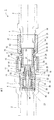
図2は、図1に示す外部調節式定流量弁1の設定通過流量を大きくした状態を示している。連結部材15は、第2接続部材12とのねじ係合の領域が短くなっており、その分、図1に示す状態よりも調節部材14はニードル弁42から離れていて、クリアランスCも広くなっている。したがって、図1よりも大きな通過流量が設定されている。
FIG. 2 shows a state in which the set passage flow rate of the externally adjustable
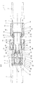
図3、4は、定流量弁1の設定通過流量を図1に示す状態から図2に示す状態に変更するときの操作の説明図である。即ち、連結部材15と第2接続部材12とのねじ係合による連結を解除して連結部材15を軸方向に移動させ、スペースSを外部に露出させると、外部から第1接続部材11と第2接続部材12との間を通して工具係合部70へのアクセスが可能となる。工具を工具係合部70に係合させて調節部材14を回転させると、調節部材14が第1接続部材11の軸方向に移動し、クリアランスCの大きさの変更、即ち、設定通過流量の変更を行うことができる。この間、調節部材14が回転しても、Oリング25、35によって第1及び第2接続部材11、12に対するシールが確保されるので、流体は外部に漏れ出ることなく、第1及び第2接続部材11、12と調節部材14の内部を通って流れることができる。設定通過流量の変更後、連結部材15を回転させて第1接続部材11と第2接続部材12とを連結する。
3 and 4 are explanatory diagrams of operations when the set passage flow rate of the
なお、上記実施形態では、第1接続部材に調節部材を移動可能に装着しているが、これに代えて第2接続部材に調節部材を移動可能に装着するようにしてもよい。
その他にも、本発明の要旨を逸脱しない範囲で上記実施形態に種々の改変を施すことができる。
In the above-described embodiment, the adjustment member is movably attached to the first connection member. Alternatively, the adjustment member may be movably attached to the second connection member.
In addition, various modifications can be made to the above embodiment without departing from the gist of the present invention.
1 外部調節式定流量弁 2、3 配管
11 第1接続部材 12 第2接続部材
13 弁部材 14 調節部材
15 連結部材 25 Oリング(シール手段)
35 Oリング(シール手段) 70 工具係合部(回転操作部)
C クリアランス
DESCRIPTION OF
35 O-ring (sealing means) 70 Tool engaging portion (rotating operation portion)
C Clearance
Claims (5)
前記一方の配管に接続される第1接続部材と、
前記他方の配管に接続される第2接続部材と、
前記第1接続部材又は第2接続部材に対して移動可能に装着された調節部材と、
前記調節部材との間に前記流体を通過させるクリアランスを形成するとともに、前記圧力差に応じて前記クリアランスを変更するように移動する弁部材と、
前記第1接続部材と前記第2接続部材とを連結するとともに、前記第1及び第2接続部材にそれぞれ配管が接続された状態で前記第1接続部材と前記第2接続部材との連結を解除することにより、前記調節部材の前記弁部材に対する位置が調節可能となるように形成された連結部材と、
を備えることを特徴とする外部調整式定流量弁。 Two pipes are connected in communication, the flow rate of the fluid is kept almost constant regardless of the pressure difference between the fluid flowing in one pipe and the fluid flowing in the other pipe, and the set passing flow rate of the fluid is An externally adjustable constant flow valve that can be adjusted from the outside.
A first connecting member connected to the one pipe;
A second connecting member connected to the other pipe;
An adjustment member movably attached to the first connection member or the second connection member;
A valve member that forms a clearance for allowing the fluid to pass between the adjustment member and moves so as to change the clearance according to the pressure difference;
The first connection member and the second connection member are connected to each other, and the connection between the first connection member and the second connection member is released in a state where the pipes are connected to the first and second connection members, respectively. A connecting member formed so that the position of the adjusting member relative to the valve member can be adjusted;
An externally adjustable constant flow valve characterized by comprising:
Priority Applications (1)
| Application Number | Priority Date | Filing Date | Title |
|---|---|---|---|
| JP2011078636A JP5659065B2 (en) | 2011-03-31 | 2011-03-31 | External adjustment type constant flow valve |
Applications Claiming Priority (1)
| Application Number | Priority Date | Filing Date | Title |
|---|---|---|---|
| JP2011078636A JP5659065B2 (en) | 2011-03-31 | 2011-03-31 | External adjustment type constant flow valve |
Publications (2)
| Publication Number | Publication Date |
|---|---|
| JP2012211677A JP2012211677A (en) | 2012-11-01 |
| JP5659065B2 true JP5659065B2 (en) | 2015-01-28 |
Family
ID=47265793
Family Applications (1)
| Application Number | Title | Priority Date | Filing Date |
|---|---|---|---|
| JP2011078636A Active JP5659065B2 (en) | 2011-03-31 | 2011-03-31 | External adjustment type constant flow valve |
Country Status (1)
| Country | Link |
|---|---|
| JP (1) | JP5659065B2 (en) |
Family Cites Families (3)
| Publication number | Priority date | Publication date | Assignee | Title |
|---|---|---|---|---|
| US2647531A (en) * | 1946-07-20 | 1953-08-04 | Brodie Ralph N Co | Flow control valve |
| JPS61103075A (en) * | 1984-10-26 | 1986-05-21 | Asahi Organic Chem Ind Co Ltd | Constant flow valve |
| JPH0682481U (en) * | 1993-05-07 | 1994-11-25 | 節子 稲田 | Free pipe in faucet |
-
2011
- 2011-03-31 JP JP2011078636A patent/JP5659065B2/en active Active
Also Published As
| Publication number | Publication date |
|---|---|
| JP2012211677A (en) | 2012-11-01 |
Similar Documents
| Publication | Publication Date | Title |
|---|---|---|
| WO2011114553A1 (en) | Valve structure for fluid pressure device | |
| JP2008232361A5 (en) | ||
| CN105518247A (en) | Device for ensuring continuous circulation in well drilling | |
| JP4491737B2 (en) | Vacuum valve | |
| JP2008196518A (en) | Flow control valve | |
| JP2016003752A (en) | Fluid controller | |
| CN111577902A (en) | Valve body assembly | |
| JP6541205B2 (en) | Stop valve and steam turbine | |
| CN105317450A (en) | A large flow safety valve | |
| US10036480B2 (en) | Clamped bonnet assembly for an axial flow valve and axial flow valve comprising same | |
| JP2008014495A (en) | Quick coupling for threaded fitting | |
| JP5659065B2 (en) | External adjustment type constant flow valve | |
| JP5746281B2 (en) | Fluid pressure cylinder | |
| JP6106498B2 (en) | Flow control device | |
| JP4676462B2 (en) | Water meter unit | |
| JP4845150B2 (en) | Pipe fitting | |
| JP6456097B2 (en) | Repair method of existing valve, existing valve, water-stopping member for repair and valve | |
| CN205534291U (en) | Case of stop valve | |
| KR20180070007A (en) | Method for manufacturing safety valve | |
| CN104153797B (en) | A valve core assembly for manipulating a valve group | |
| KR20210060657A (en) | Valve device and gas supply system | |
| JP5967271B2 (en) | Fitting and fitting mounting structure | |
| JP5784811B1 (en) | Fitting and fitting mounting structure | |
| JP7125234B2 (en) | rotating cylinder | |
| JP2013007440A (en) | Pipe joint |
Legal Events
| Date | Code | Title | Description |
|---|---|---|---|
| A621 | Written request for application examination |
Free format text: JAPANESE INTERMEDIATE CODE: A621 Effective date: 20131216 |
|
| A977 | Report on retrieval |
Free format text: JAPANESE INTERMEDIATE CODE: A971007 Effective date: 20141024 |
|
| TRDD | Decision of grant or rejection written | ||
| A01 | Written decision to grant a patent or to grant a registration (utility model) |
Free format text: JAPANESE INTERMEDIATE CODE: A01 Effective date: 20141104 |
|
| A61 | First payment of annual fees (during grant procedure) |
Free format text: JAPANESE INTERMEDIATE CODE: A61 Effective date: 20141201 |
|
| R150 | Certificate of patent or registration of utility model |
Ref document number: 5659065 Country of ref document: JP Free format text: JAPANESE INTERMEDIATE CODE: R150 |
|
| R250 | Receipt of annual fees |
Free format text: JAPANESE INTERMEDIATE CODE: R250 |
|
| R250 | Receipt of annual fees |
Free format text: JAPANESE INTERMEDIATE CODE: R250 |
|
| R250 | Receipt of annual fees |
Free format text: JAPANESE INTERMEDIATE CODE: R250 |
|
| R250 | Receipt of annual fees |
Free format text: JAPANESE INTERMEDIATE CODE: R250 |
|
| R250 | Receipt of annual fees |
Free format text: JAPANESE INTERMEDIATE CODE: R250 |