WO2011111653A1 - Canule d'introduction pour injection de ciment acrylique - Google Patents
Canule d'introduction pour injection de ciment acrylique Download PDFInfo
- Publication number
- WO2011111653A1 WO2011111653A1 PCT/JP2011/055221 JP2011055221W WO2011111653A1 WO 2011111653 A1 WO2011111653 A1 WO 2011111653A1 JP 2011055221 W JP2011055221 W JP 2011055221W WO 2011111653 A1 WO2011111653 A1 WO 2011111653A1
- Authority
- WO
- WIPO (PCT)
- Prior art keywords
- needle
- outer needle
- bone
- inner tube
- bone cement
- Prior art date
Links
Images


Classifications
-
- A—HUMAN NECESSITIES
- A61—MEDICAL OR VETERINARY SCIENCE; HYGIENE
- A61B—DIAGNOSIS; SURGERY; IDENTIFICATION
- A61B17/00—Surgical instruments, devices or methods, e.g. tourniquets
- A61B17/56—Surgical instruments or methods for treatment of bones or joints; Devices specially adapted therefor
- A61B17/58—Surgical instruments or methods for treatment of bones or joints; Devices specially adapted therefor for osteosynthesis, e.g. bone plates, screws, setting implements or the like
- A61B17/88—Osteosynthesis instruments; Methods or means for implanting or extracting internal or external fixation devices
- A61B17/8802—Equipment for handling bone cement or other fluid fillers
- A61B17/8805—Equipment for handling bone cement or other fluid fillers for introducing fluid filler into bone or extracting it
- A61B17/8819—Equipment for handling bone cement or other fluid fillers for introducing fluid filler into bone or extracting it characterised by the introducer proximal part, e.g. cannula handle, or by parts which are inserted inside each other, e.g. stylet and cannula
-
- A—HUMAN NECESSITIES
- A61—MEDICAL OR VETERINARY SCIENCE; HYGIENE
- A61B—DIAGNOSIS; SURGERY; IDENTIFICATION
- A61B17/00—Surgical instruments, devices or methods, e.g. tourniquets
- A61B17/56—Surgical instruments or methods for treatment of bones or joints; Devices specially adapted therefor
- A61B17/58—Surgical instruments or methods for treatment of bones or joints; Devices specially adapted therefor for osteosynthesis, e.g. bone plates, screws, setting implements or the like
- A61B17/88—Osteosynthesis instruments; Methods or means for implanting or extracting internal or external fixation devices
- A61B17/8802—Equipment for handling bone cement or other fluid fillers
- A61B17/8805—Equipment for handling bone cement or other fluid fillers for introducing fluid filler into bone or extracting it
- A61B17/8816—Equipment for handling bone cement or other fluid fillers for introducing fluid filler into bone or extracting it characterised by the conduit, e.g. tube, along which fluid flows into the body or by conduit connections
-
- A—HUMAN NECESSITIES
- A61—MEDICAL OR VETERINARY SCIENCE; HYGIENE
- A61B—DIAGNOSIS; SURGERY; IDENTIFICATION
- A61B17/00—Surgical instruments, devices or methods, e.g. tourniquets
- A61B17/34—Trocars; Puncturing needles
-
- A—HUMAN NECESSITIES
- A61—MEDICAL OR VETERINARY SCIENCE; HYGIENE
- A61B—DIAGNOSIS; SURGERY; IDENTIFICATION
- A61B17/00—Surgical instruments, devices or methods, e.g. tourniquets
- A61B17/56—Surgical instruments or methods for treatment of bones or joints; Devices specially adapted therefor
-
- A—HUMAN NECESSITIES
- A61—MEDICAL OR VETERINARY SCIENCE; HYGIENE
- A61B—DIAGNOSIS; SURGERY; IDENTIFICATION
- A61B17/00—Surgical instruments, devices or methods, e.g. tourniquets
- A61B17/56—Surgical instruments or methods for treatment of bones or joints; Devices specially adapted therefor
- A61B17/58—Surgical instruments or methods for treatment of bones or joints; Devices specially adapted therefor for osteosynthesis, e.g. bone plates, screws, setting implements or the like
- A61B17/88—Osteosynthesis instruments; Methods or means for implanting or extracting internal or external fixation devices
- A61B17/8802—Equipment for handling bone cement or other fluid fillers
- A61B17/8805—Equipment for handling bone cement or other fluid fillers for introducing fluid filler into bone or extracting it
- A61B17/8827—Equipment for handling bone cement or other fluid fillers for introducing fluid filler into bone or extracting it with filtering, degassing, venting or pressure relief means
-
- A—HUMAN NECESSITIES
- A61—MEDICAL OR VETERINARY SCIENCE; HYGIENE
- A61F—FILTERS IMPLANTABLE INTO BLOOD VESSELS; PROSTHESES; DEVICES PROVIDING PATENCY TO, OR PREVENTING COLLAPSING OF, TUBULAR STRUCTURES OF THE BODY, e.g. STENTS; ORTHOPAEDIC, NURSING OR CONTRACEPTIVE DEVICES; FOMENTATION; TREATMENT OR PROTECTION OF EYES OR EARS; BANDAGES, DRESSINGS OR ABSORBENT PADS; FIRST-AID KITS
- A61F2/00—Filters implantable into blood vessels; Prostheses, i.e. artificial substitutes or replacements for parts of the body; Appliances for connecting them with the body; Devices providing patency to, or preventing collapsing of, tubular structures of the body, e.g. stents
- A61F2/02—Prostheses implantable into the body
- A61F2/28—Bones
-
- A—HUMAN NECESSITIES
- A61—MEDICAL OR VETERINARY SCIENCE; HYGIENE
- A61M—DEVICES FOR INTRODUCING MEDIA INTO, OR ONTO, THE BODY; DEVICES FOR TRANSDUCING BODY MEDIA OR FOR TAKING MEDIA FROM THE BODY; DEVICES FOR PRODUCING OR ENDING SLEEP OR STUPOR
- A61M5/00—Devices for bringing media into the body in a subcutaneous, intra-vascular or intramuscular way; Accessories therefor, e.g. filling or cleaning devices, arm-rests
- A61M5/14—Infusion devices, e.g. infusing by gravity; Blood infusion; Accessories therefor
- A61M5/158—Needles for infusions; Accessories therefor, e.g. for inserting infusion needles, or for holding them on the body
- A61M2005/1587—Needles for infusions; Accessories therefor, e.g. for inserting infusion needles, or for holding them on the body suitable for being connected to an infusion line after insertion into a patient
Definitions
- the present invention relates to a puncture needle for injecting bone cement into a bone.
- Percutaneous vertebroplasty is a treatment that reinforces the vertebral body by injecting bone cement into the vertebral body in order to remove pain caused by vertebral body compression fractures.
- Percutaneous vertebroplasty is a relatively new treatment performed for the first time in France in 1987, but in recent years it has been performed in many facilities in Japan.
- a hollow puncture needle is punctured from the pedicle located on the left and right sides of the vertebral body, and bone cement is injected into the vertebral body through an injection passage in the puncture needle.
- the pedicle approach is fundamental.
- a puncture needle for injecting bone cement a bone biopsy needle is generally used (see, for example, JP-A-2003-24339).
- the pedicle approach includes a two-needle method of puncturing from both the left and right sides and a one-needle method of puncturing from only one side.
- the one-needle method is considered to be a more preferable puncture method because it has the advantages of reducing costs, reducing complications, reducing the amount of exposure, and shortening the procedure execution time compared to the two-needle method.
- the conventional puncture needle has a problem that bone cement may leak out of the bone when the bone cement is injected by the single needle method.
- the present invention has been made in view of the above circumstances, and provides a puncture needle for injecting bone cement that can inject bone cement into bone without increasing the internal pressure in the bone even with a single needle method. Objective.
- the puncture needle for bone cement injection includes a hollow outer needle having a proximal end side hole provided on a side surface in the vicinity of the proximal end portion, and is fixed to the proximal end portion of the outer needle.
- An outer needle hub having a first port communicating with the end opening, an inner needle that is provided with a needle tip at the distal end and can be inserted into the outer needle and the first port, and is fixed to a proximal end portion of the inner needle
- An inner needle hub that can be attached to and detached from the outer needle hub, an inner tube that can be inserted into the outer needle and the first port, and a base end portion of the inner tube that is detachable from the outer needle,
- An inner tube hub having a second port communicating with a proximal end opening of the inner tube, and in the state where the inner tube is inserted into the outer needle and the outer needle is pierced into the bone, A flow path communicating with the proximal end side hole is formed between the outer needle and the inner
- the inner needle is removed from the outer needle, and then the inner needle is inserted into the outer needle.
- a double tube structure is constituted by the outer needle and the inner tube.
- the outer needle is provided with a proximal end side hole, and in a state where the inner tube is inserted through the outer needle and the outer needle is punctured into the bone, a flow path that connects the inside of the bone and the proximal end side hole is provided. It is formed between the outer needle and the inner tube.
- the outer needle has a double tube structure composed of an inner tube and an outer tube, and the inner needle is inserted through the hollow portion of the inner tube. Minute, it is difficult to increase the diameter of the inner needle.
- the inner needle since the configuration in which the inner needle is inserted into the outer needle with the inner tube removed is employed, the inner needle is easily increased in diameter due to the absence of the inner tube, and the strength necessary for puncturing and removal is easily achieved. It is possible to obtain.
- the outer needle has a distal end side hole portion on a side surface near the distal end portion, and communicates the distal end side hole portion and the proximal end side hole portion with the inner tube inserted through the outer needle. Is preferably formed between the outer needle and the inner tube.
- the decompression passage between the outer needle and the inner tube communicates with the bone through the distal end side hole provided in the outer needle, so that the outer needle is pierced into the bone and
- the gas or liquid in the bone flows into the decompression passage between the outer needle and the inner tube from the distal side hole, and the pressure is reduced. It flows through the passage and flows out from the base end side hole.
- the most distal portion of the inner tube may protrude from the outer needle or at the same position as the most distal portion of the outer needle.
- the bone cement that has come out from the tip of the inner tube does not adhere to the outer needle, it is possible to reliably reinsert the inner needle into the outer needle after removing the inner tube. . Further, since the bone cement does not adhere to the outer needle, even if the inner needle is reinserted into the outer needle, the bone cement is not pushed into the bone. That is, since the bone cement is prevented from being injected more than necessary into the bone, the bone cement can be injected into the bone with an accurate injection amount.
- a decompression passage that opens at the most distal portion of the outer needle may be formed between the outer needle and the inner tube.
- the decompression passage that opens at the most distal end portion of the outer needle is formed between the outer needle and the inner tube, the outer needle is punctured into the bone and the inner tube is inserted into the outer needle.
- the gas or liquid in the bone flows into the decompression passage between the outer needle and the inner tube from the earliest opening of the outer needle, and flows through the decompression passage to the proximal end. It flows out from the side hole.
- the distal end portion of the inner tube may protrude from the distal end portion of the outer needle.
- a step between the distal end portion of the inner tube and the distal end portion of the outer needle serves as a marker under image guidance (under fluoroscopy or CT fluoroscopy). That is, since the step is easily visually recognized on the image, the outer needle can be punctured into the bone easily and reliably. Further, since the bone cement coming out from the tip of the inner tube does not adhere to the outer needle, it is possible to reliably insert the inner needle into the outer needle after removing the inner tube. Further, since bone cement does not adhere to the outer needle, even if the inner needle is reinserted into the outer needle, the bone cement is not pushed into the bone. That is, since it is prevented that the bone cement is injected more than necessary into the bone, the bone cement can be injected into the bone with an accurate injection amount.
- FIG. 2 is a partially omitted sectional view taken along line II-II in FIG. 1.
- FIG. 3 is a partially omitted cross-sectional view showing a state in which an inner tube is inserted into an outer needle of a bone cement injection puncture needle according to a first embodiment. It is a partially abbreviated enlarged view showing the distal end portion and the peripheral portion of the outer needle of the puncture needle for bone cement injection according to the first embodiment.
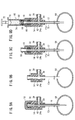
- FIG. 5A is a diagram showing a state in which the outer needle and the inner needle are punctured into the bone, FIG.
- FIG. 5B is a diagram showing a state in which the inner needle has been removed from the outer needle
- FIG. 5C is a diagram in which the inner tube is attached to the outer needle
- FIG. 5D is a diagram showing a state in which a syringe filled with bone cement is connected to the inner tube hub.
- FIG. 6A is a view showing a state in which bone cement is injected into the bone, and a gas or liquid in the bone goes out of the body through the decompression passage
- FIG. 6B shows a state in which the inner tube is removed from the outer needle.
- FIG. 6C is a diagram illustrating a state where the inner needle is remounted on the outer needle and removed from the bone.
- FIG. 6 is a partially omitted cross-sectional view of a bone cement injection puncture needle according to a second embodiment. It is a partially abbreviate
- omitted sectional drawing which shows the state which inserted the inner tube
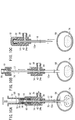
- FIG. 9A is a diagram showing a state in which the outer needle and the inner needle are punctured into the bone
- FIG. 9B is a diagram showing a state in which the inner needle is removed from the outer needle
- FIG. 9C is a diagram in which the inner tube is attached to the outer needle.
- FIG. 9D is a diagram showing a state where the syringe filled with bone cement is connected to the inner tube hub.
- FIG. 9A is a diagram showing a state in which the outer needle and the inner needle are punctured into the bone
- FIG. 9B is a diagram showing a state in which the inner needle is removed from the outer needle
- FIG. 9C
- FIG. 10A is a view showing a state in which bone cement is injected into the bone and a gas or liquid in the bone exits the body through the decompression passage
- FIG. 10B shows a state in which the inner tube is removed from the outer needle
- FIG. 10C is a diagram illustrating a state in which the inner needle is reattached to the outer needle and removed from the bone. It is a side view which shows the outer needle hub which concerns on a modification, and another structural member. It is a partially omitted sectional view of a bone cement injection puncture needle according to a third embodiment.
- bone cement includes not only bone cement (plastic preparation and the like) but also bone paste (calcium phosphate preparation and the like).
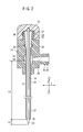
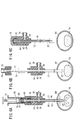
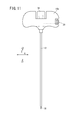
- FIG. 1 is an overall configuration diagram of a bone cement injection puncture needle 10 (hereinafter referred to as “puncture needle 10”) according to a first embodiment of the present invention.
- the puncture needle 10 includes an outer needle 12 having a hollow structure, an outer needle hub 14 fixed to a proximal end portion of the outer needle 12, and an inner needle 16 that can be inserted into the hollow portion of the outer needle 12.
- FIG. 1 shows a state where the inner needle 16 is inserted into the outer needle 12 and the inner tube 17 is removed from the outer needle 12.
- the axial direction of the inner needle 16 and the outer needle 12 is the Z direction
- the direction perpendicular to the Z direction is the X direction
- the direction perpendicular to the Z direction and the X direction is the Y direction.
- the X direction is a direction perpendicular to the Z direction and parallel to the paper surface
- the Y direction is a direction perpendicular to the paper surface.
- a direction toward the distal end side of the puncture needle 10 is defined as Z1
- a direction toward the proximal end side of the puncture needle 10 is defined as Z2.
- FIG. 2 is a partially omitted sectional view taken along line II-II in FIG.
- the outer needle 12 is a member having a hollow structure that is open at both ends, and can take the form of, for example, a hollow cylindrical tube.
- the inner needle 16 can be inserted into the hollow portion 20 of the outer needle 12.
- the length of the outer needle 12 is about 90 to 200 mm.
- the inner diameter d2 (see FIG. 3) of the outer needle 12 is, for example, about 1.5 to 3.3 mm.
- the constituent material of the outer needle 12 is not particularly limited as long as it has an appropriate strength that is not damaged or deformed during puncture to the bone and removal from the bone, but a metal is preferable, for example, stainless steel. , Aluminum alloys, copper alloys and the like.
- a first side hole (tip side hole) 22 is provided on the side surface near the tip of the outer needle 12.
- the first side hole 22 is a hole penetrating the inside and outside of the outer needle 12, and a plurality of the first side holes 22 are preferably provided in the circumferential direction and the axial direction.
- the number of the first side holes 22 is preferably 4 to 36, and more preferably 10 to 26. A preferable arrangement and dimensions of the first side hole 22 will be described later.
- a second side hole 24 (base end side hole) is provided on the side surface of the outer needle 12 near the base end.
- the second side hole 24 is a hole penetrating the inside and outside of the outer needle 12.
- the distance L1 from the most distal position of the outer needle 12 to the second side hole 24 (specifically, the most distal side (Z1 direction side) portion of the second side hole 24) is inserted by the inner needle 16.
- the second side hole 24 is set to be surely positioned outside the body.
- the distance L1 is 80 mm or more, preferably 120 mm or more.
- the number of the second side holes 24 may be one, but a plurality of the second side holes 24 may be provided in the circumferential direction or the axial direction. In the configuration example shown in FIG. 2, two second side holes 24 are provided in the circumferential direction.
- the first side hole 22 and the second side hole 24 communicate with each other via the hollow portion 20 of the outer needle 12.
- a tapered shape portion 26 is provided at the distal end portion of the outer needle 12.
- the angle of the tapered portion 26 with respect to the axis of the outer needle 12 is set to about 1 to 30 °, for example.
- the vicinity of the distal end portion of the inner needle 16 is supported by the inner peripheral portion of the tapered portion 26.
- a flare-shaped portion 28 is formed at the rear end portion of the outer needle 12.
- the flare-shaped portion 28 extends in a conical shape toward the proximal direction (Z2 direction).
- the angle of the flare shape portion 28 with respect to the axis of the outer needle 12 is set to about 15 to 60 °, for example.
- the outer peripheral surface of the flare-shaped part 28 abuts on a taper support part 30 provided in the outer needle hub 14, whereby the flare-shaped part 28 is supported by the taper support part 30.
- the outer needle hub 14 is a member coupled to the proximal end portion of the outer needle 12, and is a direction perpendicular to the axial direction of the outer needle 12 (X direction in the illustrated example) so that the user of the puncture needle can easily grasp it.
- a grip 15 (see FIG. 1) is integrally provided.
- the outer needle hub 14 is formed so as to cover the proximal end portion of the outer needle 12 and be fixed to the proximal end portion of the outer needle 12 by insert molding.
- the constituent material of the outer needle hub 14 is not particularly limited.
- styrene copolymers polyesters such as polyethylene terephthalate and polyethylene naphthalate, butadiene-styrene copolymers, polyamides (for example, nylon 6, nylon 6,6, nylon 6,10, nylon 12) and the like.
- a main connection port (first port) 32 that communicates with the hollow portion 20 of the outer needle 12 through the proximal end opening of the outer needle 12 is provided at the upper end (end in the Z2 direction) of the outer needle hub 14. Yes.
- a male thread portion 34 is formed on the outer peripheral portion of the main connection port 32, whereby the main connection port 32 can be connected to the inner needle hub 18 by screwing, and can be screwed to the inner tube hub 19. Can be connected together.
- the outer needle hub 14 is formed with a first passage 36 extending from the mouth of the main connection port 32 to a position facing the end opening of the outer needle 12.
- a sub-connecting port (third port) 38 that communicates with the hollow portion 20 of the outer needle 12 through the second side hole 24 is provided on one side surface (surface in the Y direction) of the outer needle hub 14. Yes.
- a male screw portion 40 is formed on the outer peripheral portion of the sub connection port 38, and the male screw portion 40 can be connected to another device or structure by screwing.
- the outer needle hub 14 has a second passage 42 communicating with the second side hole 24 so as to surround the outer needle 12, and a third passage extending from the second passage 42 to the mouth of the sub connection port 38. 44 is formed.
- the second passage 42 is omitted, and instead, the third passage 44 is replaced with the second side hole 24. What is necessary is just to form in the outer needle hub 14 the flow path corresponded to what extended to the position which faces.
- the inner needle 16 is a rod-like member that can be inserted into the hollow portion 20 of the outer needle 12 and has a sharp needle tip 23 at the tip.
- the constituent material of the inner needle 16 is not particularly limited as long as it has an appropriate strength that is not damaged or deformed when inserted into a bone. For example, stainless steel, aluminum alloy, copper-based alloy, etc. Is mentioned.
- the length of the inner needle 16 is set so that the tip of the inner needle 16 slightly protrudes from the tip of the outer needle 12 with the inner needle hub 18 connected to the outer needle hub 14.
- the protruding length of the inner needle 16 from the distal end of the outer needle 12 that is, the distance L2 between the distal end of the inner needle 16 and the distal end of the outer needle 12 is preferably set. 2 to 10 mm is preferable.
- the needle tip 23 may be completely exposed from the tip of the outer needle 12 with the inner needle hub 18 connected to the outer needle hub 14.
- the outer diameter of the inner needle 16 is preferably set to be substantially the same as the inner diameter of the most distal portion of the outer needle 12, and specifically, the inner needle 16 can be smoothly inserted into the hollow portion 20 of the outer needle 12, In addition, it is preferable to set the gap so that almost no gap is generated between the outer circumference of the inner needle 16 and the inner circumference of the most distal end portion of the outer needle 12.
- the inner needle hub 18 is a member coupled to the proximal end portion of the inner needle 16 and is configured to be detachable from the outer needle hub 14 without using a special tool.
- the inner needle hub 18 is formed with a female screw portion 37 that can be screwed into a male screw portion 34 formed in the main connection port 32 of the outer needle hub 14. When the inner needle hub 18 is screwed into the main connection port 32, the inner needle hub 18 can be fixed to the outer needle hub 14.
- the outer diameter of the inner needle hub 18 is set to be larger than the outer diameter of the inner needle 16, and more specifically, the user (medical staff such as a doctor) can easily pinch and pull or rotate the finger. It is set to such a size.
- the constituent material of the inner needle hub 18 is not particularly limited, but a constituent material similar to the constituent material of the outer needle hub 14, for example, a hard resin such as polycarbonate can be used.
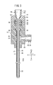
- FIG. 3 is a partially omitted cross-sectional view showing a state in which the inner tube 17 is inserted into the outer needle 12.
- the inner tube 17 is open at both ends and has a bone cement passage 46 therein.
- the length of the inner tube 17 is about 100 to 210 mm.
- the most distal portion of the inner tube 17 is the same as the most distal portion of the outer needle 12 (ie, It is preferable to set it so that it protrudes slightly from the position or from the outer needle 12.
- the inner tube 17 is a hollow cylindrical tube, and the inner diameter thereof is, for example, about 1.8 to 2.1 mm.
- the outer diameter d1 of the inner tube 17 is set smaller than the inner diameter d2 of the outer tube.
- a flare-shaped portion 50 is formed at the proximal end portion of the inner tube 17.
- the flare-shaped portion 50 extends conically toward the proximal direction (Z2 direction).
- the angle of the flare-shaped portion 50 with respect to the axis of the inner needle 16 is set to about 15 to 60 °, for example.
- the outer peripheral surface of the flare-shaped part 50 abuts on a taper support part 52 provided in the inner tube hub 19, whereby the flare-shaped part 50 is supported by the taper support part 52.
- the inner tube hub 19 is a member coupled to the proximal end portion of the inner tube 17 and is configured to be detachable from the outer needle hub 14.
- the inner tube hub 19 is formed with a female screw portion 54 that can be screwed into a male screw portion 34 formed in the main connection port 32 of the outer needle hub 14. When the inner tube hub 19 is screwed into the main connection port 32, the inner tube hub 19 can be fixed to the outer needle hub 14.
- the upper end portion (the end portion in the Z2 direction) of the inner tube hub 19 communicates with the bone cement passage 46 through the proximal end opening of the inner tube 17 to supply (transfer) bone cement to the inner tube 17.
- Injection port (second port) 56 is provided.
- a male screw part 58 is formed on the outer peripheral part of the injection port 56, and the male screw part 58 can be screwed into and connected to a syringe 66 (see FIG. 5D) as an injection device.
- the inner tube hub 19 is formed with a hollow portion 60 extending from the mouth portion of the injection port 56 to a position facing the proximal end opening of the inner tube 17.
- the outer diameter of the inner pipe hub 19 is set to be larger than the outer diameter of the inner pipe 17, and specifically, the inner pipe hub 19 is set to a size that allows the user to easily push and pull and rotate by pinching with a finger.
- the outer diameter of the inner needle hub 18 may be set substantially the same.
- a constituent material of the inner tube hub 19 is not particularly limited, but a constituent material similar to the constituent material of the outer needle hub 14, for example, a hard resin such as polycarbonate can be used.
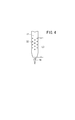
- FIG. 4 is a partially omitted enlarged view showing the first side hole 22 provided in the outer needle 12 and its periphery.
- the distance L3 from the most distal position of the outer needle 12 to the first side hole 22 located on the most proximal side (specifically, the most proximal side part of the corresponding first side hole 22) In a state where the outer needle 12 is punctured into the bone, the first side hole 22 on the most proximal side is not positioned outside the bone, that is, all the first side holes 22 are set within the bone.
- the distance L3 is 20 mm or less, preferably 15 mm or less.
- first side holes 22 When a large number of the first side holes 22 are provided, as shown in FIG. 4, they may be provided in a zigzag shape in a circumferential direction. That is, assuming that the plurality of first side holes 22 arranged in the axial direction of the outer needle 12 is one row (side hole row), the positions of the first side holes 22 in the adjacent side hole rows are in the axial direction. Each first side hole 22 is preferably arranged so as to be displaced. If comprised in this way, the strength reduction of the outer needle 12 of the area
- the sizes of the first side holes 22 are not necessarily the same, and the sizes may be different.
- the amount of the cleaning liquid sprayed from the base side of the first side hole 22 that is proximal from the sub connection port 38 is larger than that of the tip side.
- the shape of the first side hole 22 does not need to be a circle as shown in FIG. 4, and may be, for example, an ellipse or a polygon, or a mixture of different shapes.
- the size of the first side hole 22 is preferably set so that the gas or liquid in the bone (for example, exudate or blood) can smoothly flow into the outer needle 12.
- the diameter is preferably set to 0.3 to 0.7 mm.
- the size of the narrowest portion is preferably set to 0.3 to 0.7 mm.
- the liquid from the bone tends to clog the first side hole 22, but by setting the lower limit of the size of the first side hole 22 as described above, It becomes difficult for the liquid from the bone to clog the first side hole 22. If the first side hole 22 is too large, the piercing resistance increases, which causes a decrease in the smoothness of the procedure, but by setting the upper limit of the size of the first side hole 22 as described above, Increase in penetration resistance can be suppressed.
- the puncture needle 10 according to the first embodiment is basically configured as described above, and the operation and effect will be described next.
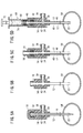
- FIG. 5A to FIG. 5D and FIG. 6A to FIG. 6C are diagrams for explaining a method of injecting bone cement into bone using the puncture needle 10.
- the outer needle 12 and the outer needle hub The assembly in which 14 is mounted on the inner needle 16 and the inner needle hub 18 is hit with a hammer to puncture the target bone 64 (see FIG. 5A).
- puncture is performed until all the first side holes 22 are located in the bone 64.
- the second side hole 22 is located outside the body.
- the puncture target bone 64 is, for example, a vertebra.
- a cleaning liquid supply tube is connected to the sub-connecting port 38, and the cleaning liquid is supplied into the outer needle 12 through the second side hole 24. May be washed.
- the inner needle 16 is removed from the outer needle 12 while the outer needle 12 is punctured into the bone 64 (see FIG. 5B).
- the inner tube 17 is inserted into the outer needle 12, and the inner tube hub 19 is connected to the main connection port 32 of the outer needle hub 14 (see FIG. 5C).
- a decompression passage 48 is formed between the outer needle 12 and the inner tube 17, and the first side hole 22 and the second side hole 24 are in communication with each other with the outer needle 12 pierced into the bone 64. .
- a cleaning solution supply tube is connected to the main connection port 32, and the cleaning solution is supplied to the bone cement passage 46 of the inner tube 17 through the second passage 42.
- the bone cement passage 46 may be cleaned.
- a cleaning liquid supply tube or a syringe filled with the cleaning liquid is connected to the sub connection port 38, and the cleaning liquid is connected to the outer needle 12 and the inner needle via the second passage 42.
- the decompression passage 48 may be supplied to the decompression passage 48 between the pipes 17 and cleaned.
- a syringe 66 as an injection device filled with bone cement 74 is connected to the injection port 56 (see FIG. 5D).
- the syringe 66 has an outer cylinder 68 configured to be connectable by screwing the tip portion with the injection port 56, and a pusher 72 provided with a gasket 70 that slides in the outer cylinder 68 at the tip.
- a bone cement 74 is filled in the cylinder 68.
- the bone cement 74 in the syringe 66 is injected into the bone 64 through the hollow portion 60 of the inner tube hub 19 and the bone cement passage 46 (see FIG. 6A).
- the gas or liquid in the bone 64 flows into the decompression passage 48 from the first side hole 22 and flows through the decompression passage 48 to the second side hole 24 and the second side hole 24. It flows out through the passage 42 and the third passage 44.
- an increase in internal pressure in the bone 64 due to the injection of the bone cement 74 is prevented, and as a result, the bone cement 74 can be prevented from leaking out of the bone 64.
- a suction device for example, a syringe
- the suction device assists the discharge of gas or liquid in the bone 64. You may do it.
- a suction device is connected to the sub-connection port 38, and before the bone cement 74 is injected into the bone, By sucking the gas or liquid, the bone 64 may be set to a negative pressure, and then the bone cement 74 may be injected into the bone 64. Thereby, an increase in the internal pressure in the bone 64 due to the injection of the bone cement 74 can be prevented.
- the inner tube 17 is removed from the outer needle 12 while the outer needle 12 is punctured into the bone 64. At this time, since the bone cement 74 is removed from the inside of the outer needle 12 with the removal of the inner tube 17, it does not adhere to the outer needle 12.
- the inner needle 16 is reinserted into the outer needle 12 and the inner needle hub 18 is connected to the outer needle hub 14.
- the bone cement 74 does not remain in the outer needle 12. For this reason, it is possible to reliably reinsert the inner needle 16 into the outer needle 12. Further, since the bone cement 74 is not pushed into the bone 64 when the inner needle 16 is reinserted, it is possible to prevent the bone cement 74 from being injected more than necessary into the bone 64. It becomes possible to inject the cement 74 with an accurate injection amount.
- the outer needle 12 and the inner needle 16 are removed from the bone 64 (see FIG. 6C).
- the puncture needle 10 As described above, according to the puncture needle 10 according to the first embodiment, after the distal end portion of the outer needle 12 and the inner needle 16 is punctured into the target bone with the inner needle 16 inserted into the outer needle 12, When the inner needle 16 is removed from the outer needle 12 and then the inner tube 17 is inserted into the outer needle 12, the outer needle 12 and the inner tube 17 constitute a double tube structure.
- the outer needle 12 is provided with a first side hole 22 and a second side hole 24.
- the first side hole 22 and the second side hole 24 are provided.
- the bone 64 and the extracorporeal space communicate with each other through the side hole 22, the decompression passage 48, and the second side hole 24.
- the gas or liquid (for example, exudate or blood) in the bone 64 can flow through the decompression passage 48 and out of the body.
- An increase in internal pressure in the bone 64 due to the injection can be prevented. Therefore, it is possible to prevent the bone cement from leaking out of the bone 64.
- first side holes 22 since a plurality of first side holes 22 are provided, even if some of the first side holes 22 are clogged with liquid from within the bone, other first side holes 22 are provided. Liquid can flow into the outer needle 12. This makes it possible to more reliably prevent an increase in internal pressure within the bone.
- the distance L3 is set within 20 mm, preferably within 15 mm so that all the first side holes 22 are located in the bone. It is possible to prevent the gas or liquid flowing into the body 12 from leaking into the body from the first side hole 22 on the proximal end side.
- the outer needle 12 may be configured as a non-separable double tube structure including an inner tube and an outer tube, and the inner needle may be inserted into the hollow portion of the inner tube. Because of the inner tube, it is difficult to increase the diameter of the inner needle.
- the diameter of the inner needle 16 is easy to enlarge and the intensity
- the outer needle 12 is prevented from coming out of the outer needle hub 14 when the puncture needle 10 is pulled out from the bone 64.
- the sub-connecting port 38 is provided in the outer needle hub 14, it is possible to easily and quickly clean the puncture needle 10 by connecting a cleaning liquid injection device to the sub-connecting port 38. Alternatively, it is possible to assist the discharge of gas or liquid in the decompression passage 48 of the puncture needle 10 by connecting a suction device.
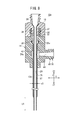
- FIG. 7 is a partially omitted cross-sectional view of a bone cement injection puncture needle 10a (hereinafter referred to as “puncture needle 10a”) according to the second embodiment.
- puncture needle 10a elements having the same or similar functions and effects as those of the puncture needle 10 according to the first embodiment are denoted by the same reference numerals, and detailed description is given. Omitted.
- the puncture needle 10a according to the second embodiment is obtained by replacing the outer needle 12 of the puncture needle 10 according to the first embodiment with an outer needle 12a having a different configuration.
- the outer needle 12a includes a flare-shaped portion 28a and a side hole (base end side hole) 24a having the same configuration as the flare-shaped portion 28 and the second side hole 24 of the outer needle 12, but is formed shorter than the outer needle 12.
- a portion corresponding to the first side hole 22 of the outer needle 12 is not provided.
- the tip of the outer needle 12a is configured as a sharp cutting edge so that the bone can be easily punctured.
- Examples of the constituent material of the outer needle 12a include the same materials as those exemplified as the constituent material of the outer needle 12.
- the outer diameter d3 of the outer needle 12a may be approximately the same as the outer diameter d2 of the outer needle 12.
- the distance L4 from the most distal end portion of the outer needle 12a to the most distal portion of the side hole 24a is set so that the side hole 24a is reliably located outside the body when the outer needle 12a is punctured into the bone.
- the distance L4 is 100 mm or more, preferably 110 mm or more.
- the protruding length of the inner needle 16 from the distal end of the outer needle 12a that is, the distance L5 between the distal end of the inner needle 16 and the distal end of the outer needle 12a is 2 It should be set to ⁇ 15 mm.
- the outer diameter of the inner needle 16 is preferably set to be substantially the same as the inner diameter d3 of the outer needle 12a. Specifically, the inner needle 16 can be smoothly inserted into the hollow portion 20 of the outer needle 12a, and the inner needle It is good to set it to such an extent that a clearance gap hardly arises between the outer periphery of 16 and the inner periphery of the outer needle 12a.
- FIG. 8 is a partially omitted sectional view showing a state in which the inner tube 17 is inserted into the outer needle 12a.
- a decompression passage 75 that opens at the most distal end portion of the outer needle 12 is formed between the outer needle 12a and the inner tube 17.
- the decompression passage 75 communicates the distal end opening of the outer needle 12a and the side hole 24a.
- the inner tube 17 preferably protrudes from the distal end portion of the outer needle 12a, and the protruding length of the inner tube 17 from the distal end of the outer needle 12a, that is, the outer
- the distance L6 between the distal end of the needle 12a and the distal end of the inner tube 17 is preferably set to 1 to 15 mm.
- FIGS. 9A to 9D and FIGS. 10A to 10C are views for explaining a method of injecting bone cement 74 into the bone 64 using the puncture needle 10a.
- a puncture position and a puncture target are determined under image guidance, and then the outer needle 12a and the outer needle hub 14 are replaced with the inner needle 16 and the inner needle.
- the assembly mounted on the hub 18 is hit with a hammer, and the outer needle 12a and the inner needle 16 are punctured into the bone to be punctured (see FIG. 9A).
- puncture is performed until the distal end opening of the outer needle 12 a is located in the bone 64.
- the side hole 24a is located outside the body in a state where the outer needle 12a and the inner needle 16 are punctured into the bone 64.
- the outer needle 12a and the inner needle 16 are moved under image guidance.
- a step between the distal end portion of the inner tube 17 and the distal end portion of the outer needle 12a serves as a marker. That is, since the level difference is easily visually recognized on the image, the outer needle 12a can be punctured into the bone easily and reliably. Further, by confirming the step (marker) with X-rays, it can be determined that the tip of the decompression passage 75 has been inserted into the bone.
- the inner needle 16 is removed from the outer needle 12a while the outer needle 12a is pierced into the bone (see FIG. 9B).
- the inner tube 17 is inserted into the outer needle 12a, and the inner tube hub 19 is connected to the main connection port 32 of the outer needle hub 14 (see FIG. 9C).
- a decompression passage 75 is formed between the outer needle 12a and the inner tube 17, and the inside of the bone 64 and the side hole 24a are in communication with each other with the outer needle 12a punctured into the bone 64.
- a syringe 66 as an injection device filled with bone cement 74 is connected to the injection port 56 (see FIG. 9D).
- the bone cement 74 in the syringe 66 is injected into the bone 64 through the hollow portion 60 of the inner tube hub 19 and the bone cement passage 46 (see FIG. 10A).
- the gas or liquid in the bone 64 flows into the decompression passage 75 from the opening of the distal end of the outer needle 12a, and flows out through the decompression passage 75 to the outside through the side hole 24a. To do.
- an increase in internal pressure in the bone 64 due to the injection of the bone cement 74 is prevented, and as a result, the bone cement 74 can be prevented from leaking out of the bone 64.
- a suction device for example, a syringe
- a suction device may be connected to the sub connection port 38 to assist the discharge of gas or liquid in the bone 64.
- a suction device is connected to the sub-connection port 38, and before the bone cement 74 is injected into the bone 64, the suction device inserts the bone 64 into the bone 64.
- the bone 64 may be set to a negative pressure, and then the bone cement 74 may be injected into the bone 64. Thereby, an increase in the internal pressure in the bone 64 due to the injection of the bone cement 74 can be prevented.
- the inner tube 17 is removed from the outer needle 12a while the outer needle 12a is punctured into the bone 64 (see FIG. 10B). At this time, since the bone cement 74 is removed from the inside of the outer needle 12a with the removal of the inner tube 17, it does not adhere to the outer needle 12a.
- the inner needle 16 is reinserted into the outer needle 12 a and the inner needle hub 18 is connected to the outer needle hub 14.
- the bone cement 74 does not remain in the outer needle 12a. For this reason, it is possible to reliably reinsert the inner needle 16 into the outer needle 12a. Further, since the bone cement 74 is not pushed into the bone 64 when the inner needle 16 is reinserted, the bone 64 is prevented from being injected more than necessary into the bone 64. It becomes possible to inject the bone cement 74 with an accurate injection amount.
- the outer needle 12a and the inner needle 16 are removed from the bone 64 (see FIG. 10C).
- the puncture needle 10a after the outer needle 12a and the distal end portion of the inner needle 16 are punctured into the target bone 64 with the inner needle 16 inserted into the outer needle 12a,
- the outer needle 12a and the inner tube 17 constitute a double tube structure.
- the outer needle 12a is provided with a side hole, and when the inner tube 17 is inserted through the outer needle 12a and the outer needle 12a is punctured into the bone 64, the bone 64 is passed through the decompression passage 75 and the side hole 24a.
- the inside and outside spaces communicate with each other.
- the gas or liquid (for example, exudate or blood) in the bone 64 can flow through the decompression passage 75 and get out of the body.
- An increase in internal pressure in the bone 64 due to the injection of 74 can be prevented. Therefore, it is possible to prevent the bone cement 74 from leaking out of the bone 64.
- the sub connection port 38 is provided on the side surface (the surface facing the Y direction) of the outer needle hub 14 has been described.
- the outer needle hub according to the modification shown in FIG. It is good also as a structure which provides the sub connection port 39 in one edge part (edge part of a X direction) of the left-right direction like 14a.
- the sub connection port 39 has the same function as the sub connection port 38 and can be connected to other devices and structures such as a suction device.
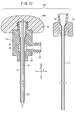
- FIG. 12 is a partially omitted cross-sectional view of a bone cement injection puncture needle 10b (hereinafter referred to as “puncture needle 10b”) according to a third embodiment.
- Puncture needle 10b a bone cement injection puncture needle 10b
- elements having the same or similar functions and effects as those of the puncture needle 10 according to the first embodiment are denoted by the same reference numerals, and detailed description is given. Omitted.
- the outer needle hub 14 is provided with the grip 15 for the user of the puncture needles 10 and 10a to hold (see FIG. 1).
- a grip 76 extending in a direction perpendicular to the axial direction of the inner needle 16 is provided on the inner needle hub 18a, and the grip 15 of the outer needle hub 14 is provided on the outer needle hub 14b. No equivalent is provided.
- the outer needle hub 14 b has the same configuration as that of the outer needle hub 14 except that no grip is provided, and includes a first passage 36, a second passage 42, and a sub connection port 38.
- the inner needle hub 18a has the same configuration as the inner needle hub 18 except that a grip 76 is provided.
- the outer needle 12 may be replaced with the outer needle 12a of the puncture needle 10a according to the second embodiment.
- the puncture needle 10b bone cement is injected into the bone via the bone cement passage 46 in the inner tube 17 in the same manner as the puncture needles 10 and 10a according to the first and second embodiments. Then, the inner tube 17 is removed from the outer needle 12 so that the bone cement does not adhere to the outer needle 12.
- the grip 76 is provided not on the outer needle hub 14b but on the inner needle hub 18a. That is, since the inner tube 17 can be reliably reinserted into the outer needle 12 by preventing bone cement from adhering to the outer needle 12, the grip 76 is provided on the inner needle hub 18a to which the inner needle 16 is fixed. Thereby, since the grip 76 is removed from the outer needle hub 14 at the time of bone cement injection, the grip 76 does not get in the way at the time of bone cement injection, and the procedure is smoothly performed. Can be performed.
Abstract
Priority Applications (5)
| Application Number | Priority Date | Filing Date | Title |
|---|---|---|---|
| ES11753311.7T ES2594977T3 (es) | 2010-03-09 | 2011-03-07 | Aguja de punción de inyección de cemento para huesos |
| EP11753311.7A EP2545872B1 (fr) | 2010-03-09 | 2011-03-07 | Canule d'introduction pour injection de ciment acrylique |
| CN201180013097.4A CN102791209B (zh) | 2010-03-09 | 2011-03-07 | 骨粘固剂注入用穿刺针 |
| KR1020127023473A KR101692096B1 (ko) | 2010-03-09 | 2011-03-07 | 골 시멘트 주입용 천자침 |
| US13/582,296 US20120330320A1 (en) | 2010-03-09 | 2011-03-07 | Bone cement injection puncture needle |
Applications Claiming Priority (2)
| Application Number | Priority Date | Filing Date | Title |
|---|---|---|---|
| JP2010052300A JP5649108B2 (ja) | 2010-03-09 | 2010-03-09 | 骨セメント注入用穿刺針 |
| JP2010-052300 | 2010-03-09 |
Publications (1)
| Publication Number | Publication Date |
|---|---|
| WO2011111653A1 true WO2011111653A1 (fr) | 2011-09-15 |
Family
ID=44563455
Family Applications (1)
| Application Number | Title | Priority Date | Filing Date |
|---|---|---|---|
| PCT/JP2011/055221 WO2011111653A1 (fr) | 2010-03-09 | 2011-03-07 | Canule d'introduction pour injection de ciment acrylique |
Country Status (7)
| Country | Link |
|---|---|
| US (1) | US20120330320A1 (fr) |
| EP (2) | EP2545872B1 (fr) |
| JP (1) | JP5649108B2 (fr) |
| KR (1) | KR101692096B1 (fr) |
| CN (1) | CN102791209B (fr) |
| ES (1) | ES2594977T3 (fr) |
| WO (1) | WO2011111653A1 (fr) |
Cited By (3)
| Publication number | Priority date | Publication date | Assignee | Title |
|---|---|---|---|---|
| CN102871713A (zh) * | 2012-10-24 | 2013-01-16 | 李建民 | 一种应用于经皮椎体成形术中的骨水泥注入装置 |
| CN104853685A (zh) * | 2012-11-16 | 2015-08-19 | 斯皮纳产生有限责任公司 | 多通道插管及使用其的方法 |
| US10231846B2 (en) | 2016-08-19 | 2019-03-19 | Stryker European Holdings I, Llc | Bone graft delivery loading assembly |
Families Citing this family (11)
| Publication number | Priority date | Publication date | Assignee | Title |
|---|---|---|---|---|
| JP5649108B2 (ja) | 2010-03-09 | 2015-01-07 | テルモ株式会社 | 骨セメント注入用穿刺針 |
| WO2012170805A2 (fr) * | 2011-06-09 | 2012-12-13 | Knee Creations, Llc | Instruments et dispositifs pour réparer une articulation sous-chondrale |
| US20130072941A1 (en) * | 2011-09-16 | 2013-03-21 | Francisca Tan-Malecki | Cement Injector and Cement Injector Connectors, and Bone Cement Injector Assembly |
| US9833272B2 (en) * | 2012-11-16 | 2017-12-05 | Spinal Generations, Llc | Multichannel cannula and methods for using same |
| KR101548809B1 (ko) | 2013-10-30 | 2015-08-31 | 삼성전기주식회사 | 오일주입용 노즐 |
| US20170014166A1 (en) * | 2014-02-21 | 2017-01-19 | The Sydney Children's Hospitals Network (Randwick And Westmead) | An implantable device |
| US9615863B2 (en) | 2014-10-22 | 2017-04-11 | Spinal Generations, Llc | Multichannel cannula for kyphoplasty and method of use |
| CN106955149A (zh) * | 2016-01-11 | 2017-07-18 | 薛绍刚 | 骨水泥注射器 |
| US11510696B2 (en) * | 2017-03-15 | 2022-11-29 | Smith & Nephew, Inc. | Graft preparation and delivery instruments and method |
| KR102108620B1 (ko) | 2018-03-09 | 2020-05-08 | 강호상 | 척추성형술용 니들 세트 |
| CN109363762A (zh) * | 2018-12-18 | 2019-02-22 | 艾科美医疗器械(深圳)有限公司 | 一种负压吸入式骨水泥灌注装置及灌注方法 |
Citations (2)
| Publication number | Priority date | Publication date | Assignee | Title |
|---|---|---|---|---|
| JP2004513741A (ja) * | 2000-10-24 | 2004-05-13 | カイフォン インコーポレイテッド | 内部身体領域にアクセスする携帯型器具 |
| JP2008259810A (ja) * | 2007-03-16 | 2008-10-30 | Olympus Terumo Biomaterials Corp | 椎体圧迫骨折整復ユニット |
Family Cites Families (10)
| Publication number | Priority date | Publication date | Assignee | Title |
|---|---|---|---|---|
| US5800439A (en) * | 1997-05-16 | 1998-09-01 | Clyburn; Terry A. | Cement injection and intramedullary canal drying system |
| JP3877982B2 (ja) | 2001-07-17 | 2007-02-07 | 株式会社八光 | 組織採取機能を有する生体用セメント注入器具 |
| US20040097880A1 (en) * | 2002-11-19 | 2004-05-20 | Angiodynamics, Inc. | Combination thrombolytic infusion catheter and dilator system |
| ES2531134T3 (es) * | 2005-09-07 | 2015-03-11 | Thomas Steffen | Dispositivo para la inyección de material de alta viscosidad |
| US20080119821A1 (en) * | 2006-11-17 | 2008-05-22 | Warsaw Orthopedic, Inc. | Multiport Cannula |
| US8696679B2 (en) * | 2006-12-08 | 2014-04-15 | Dfine, Inc. | Bone treatment systems and methods |
| WO2008114483A1 (fr) * | 2007-03-16 | 2008-09-25 | Olympus Terumo Biomaterials Corp. | Dispositif permettant de fixer une fracture osseuse provoquée par une compression pyramidale |
| KR100950989B1 (ko) * | 2008-07-03 | 2010-04-02 | (주)태연메디칼 | 뼈 충진 물질의 경피전달용 장치 |
| US8070728B2 (en) * | 2009-05-05 | 2011-12-06 | Societe De Commercialisation Des Produits De La Recherche Appliquee Socpra Sciences Et Genie S.E.C | Cannula assembly with detachable inner and outer cannulas |
| JP5649108B2 (ja) | 2010-03-09 | 2015-01-07 | テルモ株式会社 | 骨セメント注入用穿刺針 |
-
2010
- 2010-03-09 JP JP2010052300A patent/JP5649108B2/ja not_active Expired - Fee Related
-
2011
- 2011-03-07 WO PCT/JP2011/055221 patent/WO2011111653A1/fr active Application Filing
- 2011-03-07 ES ES11753311.7T patent/ES2594977T3/es active Active
- 2011-03-07 EP EP11753311.7A patent/EP2545872B1/fr not_active Not-in-force
- 2011-03-07 CN CN201180013097.4A patent/CN102791209B/zh not_active Expired - Fee Related
- 2011-03-07 KR KR1020127023473A patent/KR101692096B1/ko active IP Right Grant
- 2011-03-07 US US13/582,296 patent/US20120330320A1/en not_active Abandoned
- 2011-03-07 EP EP15201674.7A patent/EP3017779B1/fr not_active Not-in-force
Patent Citations (2)
| Publication number | Priority date | Publication date | Assignee | Title |
|---|---|---|---|---|
| JP2004513741A (ja) * | 2000-10-24 | 2004-05-13 | カイフォン インコーポレイテッド | 内部身体領域にアクセスする携帯型器具 |
| JP2008259810A (ja) * | 2007-03-16 | 2008-10-30 | Olympus Terumo Biomaterials Corp | 椎体圧迫骨折整復ユニット |
Cited By (5)
| Publication number | Priority date | Publication date | Assignee | Title |
|---|---|---|---|---|
| CN102871713A (zh) * | 2012-10-24 | 2013-01-16 | 李建民 | 一种应用于经皮椎体成形术中的骨水泥注入装置 |
| CN104853685A (zh) * | 2012-11-16 | 2015-08-19 | 斯皮纳产生有限责任公司 | 多通道插管及使用其的方法 |
| US10231846B2 (en) | 2016-08-19 | 2019-03-19 | Stryker European Holdings I, Llc | Bone graft delivery loading assembly |
| US10857001B2 (en) | 2016-08-19 | 2020-12-08 | Stryker European Holdings I, Llc | Bone graft delivery loading assembly |
| US11666456B2 (en) | 2016-08-19 | 2023-06-06 | Stryker European Operations Holdings Llc | Bone graft delivery loading assembly |
Also Published As
| Publication number | Publication date |
|---|---|
| JP5649108B2 (ja) | 2015-01-07 |
| JP2011182996A (ja) | 2011-09-22 |
| US20120330320A1 (en) | 2012-12-27 |
| EP3017779B1 (fr) | 2017-05-31 |
| ES2594977T3 (es) | 2016-12-27 |
| EP2545872B1 (fr) | 2016-08-10 |
| CN102791209A (zh) | 2012-11-21 |
| KR20120129948A (ko) | 2012-11-28 |
| KR101692096B1 (ko) | 2017-01-17 |
| EP3017779A1 (fr) | 2016-05-11 |
| EP2545872A1 (fr) | 2013-01-16 |
| EP2545872A4 (fr) | 2014-10-29 |
| CN102791209B (zh) | 2015-08-26 |
Similar Documents
| Publication | Publication Date | Title |
|---|---|---|
| JP5649108B2 (ja) | 骨セメント注入用穿刺針 | |
| WO2010044462A1 (fr) | Aiguille d'injection de ciment osseux | |
| EP2699181B1 (fr) | Canule et trousse d'évaluation et de préparation de tissu osseux | |
| KR102031325B1 (ko) | 조직을 흡인하기 위한 장치 | |
| US20040153005A1 (en) | Bone marrow aspiration device with curved tip | |
| US5423764A (en) | Lavage apparatus | |
| US20100286616A1 (en) | Cannula assembly with detachable inner and outer cannulas | |
| US20010018584A1 (en) | Method for protecting soft tissue while drilling into underlying bone | |
| WO2011111652A1 (fr) | Canule d'introduction pour injection de ciment acrylique | |
| JP6038655B2 (ja) | コネクタ組立体 | |
| JP2011182995A (ja) | 骨セメント注入用穿刺針 | |
| CN209826799U (zh) | 一种螺壳旋切式同轴穿刺活检针 | |
| CN212066816U (zh) | 一种组合式穿刺针 | |
| CN213993687U (zh) | 一次性快速穿刺闭式引流装置 | |
| WO2014049790A1 (fr) | Aiguille de perforation pour l'injection de ciment osseux et procédé pour la produire | |
| CN217014168U (zh) | 一种防堵塞腹腔穿刺导流管 | |
| WO2012043289A1 (fr) | Aiguille de perforation pour l'injection d'un ciment osseux et son procédé de fabrication |
Legal Events
| Date | Code | Title | Description |
|---|---|---|---|
| WWE | Wipo information: entry into national phase |
Ref document number: 201180013097.4 Country of ref document: CN |
|
| 121 | Ep: the epo has been informed by wipo that ep was designated in this application |
Ref document number: 11753311 Country of ref document: EP Kind code of ref document: A1 |
|
| WWE | Wipo information: entry into national phase |
Ref document number: 13582296 Country of ref document: US |
|
| ENP | Entry into the national phase |
Ref document number: 20127023473 Country of ref document: KR Kind code of ref document: A |
|
| REEP | Request for entry into the european phase |
Ref document number: 2011753311 Country of ref document: EP |
|
| WWE | Wipo information: entry into national phase |
Ref document number: 2011753311 Country of ref document: EP |
|
| NENP | Non-entry into the national phase |
Ref country code: DE |