WO2011108532A1 - パレット台車の漏風検知システム、パレット台車の漏風検知方法 - Google Patents
パレット台車の漏風検知システム、パレット台車の漏風検知方法 Download PDFInfo
- Publication number
- WO2011108532A1 WO2011108532A1 PCT/JP2011/054605 JP2011054605W WO2011108532A1 WO 2011108532 A1 WO2011108532 A1 WO 2011108532A1 JP 2011054605 W JP2011054605 W JP 2011054605W WO 2011108532 A1 WO2011108532 A1 WO 2011108532A1
- Authority
- WO
- WIPO (PCT)
- Prior art keywords
- pallet truck
- pallet
- oxygen concentration
- identification information
- cart
- Prior art date
- Legal status (The legal status is an assumption and is not a legal conclusion. Google has not performed a legal analysis and makes no representation as to the accuracy of the status listed.)
- Ceased
Links
Images





Classifications
-
- C—CHEMISTRY; METALLURGY
- C22—METALLURGY; FERROUS OR NON-FERROUS ALLOYS; TREATMENT OF ALLOYS OR NON-FERROUS METALS
- C22B—PRODUCTION AND REFINING OF METALS; PRETREATMENT OF RAW MATERIALS
- C22B1/00—Preliminary treatment of ores or scrap
- C22B1/14—Agglomerating; Briquetting; Binding; Granulating
- C22B1/16—Sintering; Agglomerating
- C22B1/20—Sintering; Agglomerating in sintering machines with movable grates
-
- F—MECHANICAL ENGINEERING; LIGHTING; HEATING; WEAPONS; BLASTING
- F27—FURNACES; KILNS; OVENS; RETORTS
- F27B—FURNACES, KILNS, OVENS OR RETORTS IN GENERAL; OPEN SINTERING OR LIKE APPARATUS
- F27B21/00—Open or uncovered sintering apparatus; Other heat-treatment apparatus of like construction
- F27B21/06—Endless-strand sintering machines
-
- F—MECHANICAL ENGINEERING; LIGHTING; HEATING; WEAPONS; BLASTING
- F27—FURNACES; KILNS; OVENS; RETORTS
- F27B—FURNACES, KILNS, OVENS OR RETORTS IN GENERAL; OPEN SINTERING OR LIKE APPARATUS
- F27B19/00—Combinations of different kinds of furnaces that are not all covered by any single one of main groups F27B1/00 - F27B17/00
-
- F—MECHANICAL ENGINEERING; LIGHTING; HEATING; WEAPONS; BLASTING
- F27—FURNACES; KILNS; OVENS; RETORTS
- F27D—DETAILS OR ACCESSORIES OF FURNACES, KILNS, OVENS OR RETORTS, IN SO FAR AS THEY ARE OF KINDS OCCURRING IN MORE THAN ONE KIND OF FURNACE
- F27D19/00—Arrangements of controlling devices
-
- F—MECHANICAL ENGINEERING; LIGHTING; HEATING; WEAPONS; BLASTING
- F27—FURNACES; KILNS; OVENS; RETORTS
- F27D—DETAILS OR ACCESSORIES OF FURNACES, KILNS, OVENS OR RETORTS, IN SO FAR AS THEY ARE OF KINDS OCCURRING IN MORE THAN ONE KIND OF FURNACE
- F27D21/00—Arrangement of monitoring devices; Arrangement of safety devices
Definitions
- the present invention relates to a technology for detecting a leakage of a pallet truck used for manufacturing sintered ore as a blast furnace raw material and detecting damage to the pallet truck.
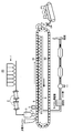
- a sinter ore manufacturing facility (hereinafter referred to as a sintering machine) 20 that is a blast furnace raw material will be described.
- the sintering machine 20 has a large number of pallet carriages 6 that are continuously connected in the moving direction and move on an elliptical orbit.
- the pallet carriage 6 has a box shape with the upper part opened, and is loaded with raw materials for sintered ore, which will be described later.
- a lattice-shaped ventilation portion 6 a is formed on the bottom surface of the pallet carriage 6 so that the raw material cannot pass but can be vented.
- FIG. 12 a lattice-shaped ventilation portion 6 a is formed on the bottom surface of the pallet carriage 6 so that the raw material cannot pass but can be vented.
- a number of bag-like window boxes 7 are fixed below the track of the pallet truck 6 so as to be adjacent to the movement direction of the pallet truck 6.
- the upper opening of the wind box 7 faces the ventilation part 6 a of the pallet carriage 6.
- a bag-like window leg 8 branched in a bifurcated shape is formed below the window box 7.
- Each wind leg 8 is connected to a main duct 9.
- the main duct 9 is connected to an intake device 11 such as a blower. When the intake device 11 is driven, air flows from the upper side to the lower side of the pallet carriage 6.
- an air seal bar 10 that contacts the upper end of the wind box 7 is attached to the lower end of the pallet cart 6 so as to be movable in the vertical direction.
- a heat-resistant grease is applied to the contact portion of the pallet carriage 6.
- Each raw material tank 1 stores raw materials of sintered ore made of iron ore, coke, and limestone.
- the mixer 2 is an apparatus for mixing and granulating the raw materials supplied from the raw material tank 1 while adding moisture.
- the raw material granulated by the mixer 2 is put into the surge hopper 3 and charged into the pallet truck 6 by the drum feeder 4 provided at the lower end of the surge hopper 3, and as shown in FIG. Is formed.
- An ignition furnace 5 having a large number of burners is disposed at a downstream position adjacent to the drum feeder 4, and the raw material charged in the pallet carriage 6 is ignited by the ignition furnace 5.
- the coke in the raw material layer 99 is combusted, and the raw material layer 99 is sequentially fired from the upper side to the lower side by the combustion heat.
- firing of the raw material layer 99 proceeds, and sintered ore is continuously generated in about 30 to 50 minutes.
- the number of pallet trucks 6 is 100 to 160, and the time required for the pallet truck 6 to make one round of the orbit is 1 hour to 1 and a half hours.
- the inner upper part 6d of the end face liner 6c located below the sidewall 6b of the pallet truck 6 is scraped by friction with the raw material spilling from the upper raw material layer. Then, the air flow resistance of the inner upper portion 6d of the missing end liner 6c is reduced, and air preferentially flows through the portion where the raw material layer 99 is in contact with the sidewall 6b (air leakage 1 shown in FIG. 12). ), The amount of air flow to the raw material layer 99 decreases.
- the air seal bar 10 is scraped and damaged by abrasion due to sliding with the upper end of the wind box 7. Then, air enters from the damaged portion of the air seal bar 10 (air leakage 2 shown in FIG.
- the amount of air flowing to the raw material layer 99 decreases. If the flow rate of air to the raw material layer 99 is reduced, the raw material layer 99 is not sufficiently fired. Conventionally, in order to prevent this, the suction amount in the intake device 11 is increased by the amount of air leakage. Thus, the air circulation amount to the raw material layer 99 was compensated. For this reason, the electric power consumption which drives the intake device 11 increased, and energy was consumed uselessly. In particular, when the inner upper portion 6d of the end face liner 6c is scraped and damaged, air flows in preference to the damaged portion, so that the powdery raw material 99 flows through the damaged portion, and the inner upper portion 6d of the end face liner 6c is scraped by wear.
- Patent Document 1 to Patent Document 3 an oxygen sensor is arranged in the wind box 7 and the oxygen leakage contained in the gas flowing through the wind box 7 is measured to measure the air leakage.
- a position measuring device is attached to each of the pallet carts 6 to measure the position of the pallet carts 6, and from the oxygen concentration measurement value obtained by the oxygen sensor and the position information of the pallet carts 6, the air leakage is detected.
- the pallet truck 6 is specified.
- Patent Document 3 does not disclose what method is used to measure the position of the pallet truck 6 to identify the leaking pallet truck 6.
- This invention solves the said problem and aims at providing the technique which can detect the pallet trolley
- the present invention provides: A plurality of pallet trucks that are continuously connected in the moving direction of the orbital track, have a ventilation portion on the bottom surface, and are loaded with sintered ore raw materials; A plurality of wind boxes disposed below the orbit, An air leakage detection system for a pallet truck of a sintering machine, which includes an intake device that sucks the inside of the wind box and circulates air from above to below the pallet truck, An oxygen sensor for measuring the oxygen concentration in the windbox; A display member that is affixed to a side surface of the pallet truck, and that displays a two-dimensional code in which identification information of the pallet truck is patterned, A reading device for reading the identification information described on the display member; A storage unit for storing an oxygen concentration value in the window box measured by the oxygen sensor and the identification information of the pallet carriage read by the reader; The display device includes display means for displaying the identification information stored in the storage unit in association with the oxygen concentration value.
- the storage unit further stores a measurement time of the oxygen concentration value by the oxygen sensor and a reading time of the identification information of the pallet truck by the reader.
- the passage start time and the passage end time on the oxygen sensor of the pallet truck are calculated from the reading time stored in the storage unit, and stored in the storage unit between the passage start time and the passage end time.
- the display means displays a history of the oxygen concentration value of the associated pallet truck. Thereby, it becomes possible to detect the degree of damage of each pallet truck, and to determine the deterioration period.
- the apparatus further comprises alarm notifying means for specifying the pallet truck and notifying an alarm when the oxygen concentration value associated with the pallet truck exceeds a predetermined threshold value.
- the identification information of the pallet truck is arranged in descending order of the number of times that the oxygen concentration value associated with the pallet truck stored in the storage unit is equal to or higher than a predetermined value, and the pallet truck of the higher-order identification information is prioritized.
- the vehicle further has a repair priority order judging means for judging a pallet truck to be repaired. Thereby, it becomes possible to recognize the pallet truck which should be repaired with priority.
- the two-dimensional code displayed on the display member has a complementary code, and the identification information of the pallet truck is made redundant by the complementary code. Thereby, even if the surface of the display member displaying the two-dimensional code is soiled by dust, the identification information of the pallet truck can be read. For this reason, it becomes possible to reliably detect a pallet truck in which air leakage has occurred due to damage.
- the present invention is continuously connected in the moving direction of the orbital track, a ventilation portion is formed on the bottom surface, and a plurality of pallet trucks loaded with sintered ore raw materials, A plurality of wind boxes disposed below the orbit, A method for detecting a leakage of air from a pallet truck in a sintering machine comprising an intake device that sucks the inside of the wind box and distributes air downward from above the pallet truck, Measuring the oxygen concentration in the windbox; Reading identification information of the pallet truck described in a two-dimensional code displayed on a display member attached to a side surface of the pallet truck; Displaying the measured oxygen concentration value in the window box in correspondence with the read identification information of the pallet truck; It is characterized by including.
- the identification information is read by the reading device from the display member that displays the two-dimensional code affixed to the side surface of each pallet truck, and the read identification information is associated with the oxygen concentration value in the window box.
- This makes it possible to detect a pallet truck that has leaked air due to damage to the pallet truck. Thereby, it becomes possible to prioritize the pallet trucks that need repair, and the trucks can be efficiently exchanged. Further, it is possible to grasp the history of the oxygen concentration value of each pallet truck, determine the deterioration cycle of each pallet truck, and prevent an increase in air leakage. As a result, the increase in air leakage is suppressed, and the power consumption for driving the intake device can be reduced. In addition, when about 10% of the 160 pallet trucks are replaced, the power consumption for driving the intake device can be reduced by about 5%.
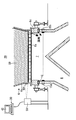
- FIG. 1 is a side view of a pallet truck and a wind box.
- FIG. 2 is a cross-sectional view of the pallet truck and the wind box.
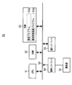
- FIG. 3 is a block diagram of the processing unit.
- FIG. 4 is a block diagram of the reading device.
- FIG. 5 is a flowchart of the main process.
- FIG. 6 is a graph showing the oxygen concentration history of the windbox.
- FIG. 7 is a table showing the oxygen concentration history of the pallet truck.
- FIG. 8 is a graph showing the oxygen concentration history of a specific pallet truck.
- FIG. 9 is a table showing the cart number and the number of alarms.
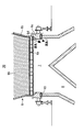
- FIG. 10 is an explanatory diagram of another example in which the mounting position of the reading device is disposed below the oxygen sensor.
- FIG. 11 is a production process diagram of sintered ore.
- FIG. 12 is a cross-sectional view of a conventional pallet truck and wind box.
- a preferred embodiment of a pallet truck air leakage detection system according to the present invention will be described below with reference to the drawings.
- the basic configuration of the sintering machine 20 is as described above, and will be supplementarily described below.
- a plurality of wind boxes 7 are closely arranged in the direction of travel of the pallet carriage 6 (the direction indicated by the arrow in FIG. 1). In the embodiment shown in FIG. 1, the length of the wind box 7 is longer than the length of the pallet carriage 6 in the traveling direction.
- An oxygen sensor 15 that measures the oxygen concentration in the wind box 7 is disposed in the wind box 7.
- the oxygen sensor 15 used in the present embodiment is a laser-type oxygen sensor including a light emitting unit 15a that emits laser light and a light receiving unit 15b that receives the laser.
- the light emitting portion 15 a and the light receiving portion 15 b are respectively attached to the wall surface of one wind box 7 that faces in the direction orthogonal to the traveling direction of the pallet carriage 6.
- the light emitting portion 15 a and the light receiving portion 15 b are disposed at an intermediate position in the longitudinal direction of the wind box 7.
- a display member 60 for displaying a two-dimensional code is attached to one side surface (including the sidewall 6b) facing each pallet truck 6 in the direction orthogonal to the traveling direction.
- the two-dimensional code is obtained by converting binary code data into cells and arranging them in a pattern on a two-dimensional matrix.
- “identification information” of each pallet carriage 6 is described in a pattern. Yes.
- the “identification information” is a cart number of the pallet cart 6.
- the two-dimensional code is a QR code (registered trademark) described in Japanese Patent No. 2938338.
- the display member 60 that displays a two-dimensional code has a configuration in which the pattern is described with ceramic ink on a base material of a heat-resistant resin sheet such as polyimide, and has heat resistance.
- the side surface of the pallet carriage 6 is heated up to 200 ° C., but the heat resistance temperature of the display member 60 displaying the two-dimensional code of this embodiment is about 300 ° C., and the display member displaying the two-dimensional code by heat. 60 does not melt.
- the base material may be made of silicon or ceramics. In the present embodiment, since the ceramic ink is used, the pattern does not fade due to heat.
- a reading device 50 is disposed above the oxygen sensor 15.
- the reading device 50 is disposed at a position facing the trajectory of the display member 60 that displays the moving two-dimensional code.
- the separation distance between the reading device 50 and the display member 60 that displays the two-dimensional code is about 1 m.
- the reading device 50 is a device that reads “identification information” of each pallet carriage 6 described in each two-dimensional code. The configuration of the reading device 50 will be described later in detail.
- the “identification information” of each pallet carriage 6 read by each reading device 50 is transmitted to the processing unit 30 and is associated with the “oxygen concentration value” in the wind box 7 measured by the oxygen sensor 15 to be processed by the processing unit.
- 30 non-volatile storage devices 34 shown in FIG. 3).
- the processing unit 30 includes a CPU 31, a RAM 32, a ROM 33, a nonvolatile storage device 34, an interface 35, a communication interface 36, and a display unit drive circuit 37. These components are connected to each other by a bus 39.
- a display unit 42 made up of an LCD or the like is connected to the display unit drive circuit 37.
- the reading device 50 is connected to the communication interface 36.
- the CPU 31 performs various calculations and processing in cooperation with RAM 32 and ROM 33.
- the RAM 32 temporarily stores a program processed by the CPU 31 and data processed by the CPU 31 in its address space.
- the ROM 33 stores various programs and parameters for controlling the processing unit 30. The various programs are processed by the CPU 31 to realize various functions.
- the ROM 33 stores a cart oxygen concentration association program 33a, an information display program 33b, an alarm notification program 33c, and a cart repair priority determination program 33d. It should be noted that these programs and data may be stored in the nonvolatile storage device 34.
- the cart oxygen concentration association program 33 a When receiving the “identification information” of the pallet truck 6 from the communication interface 36, the cart oxygen concentration association program 33 a obtains the “identification information” and the “oxygen concentration value” in the windbox 7 received by the interface 35. This is a program that is associated and sequentially stored in the cart oxygen concentration history storage area 34c.
- the trolley oxygen concentration association program 33a and the CPU 31 that processes the trolley oxygen concentration association program 33a function as a trolley oxygen concentration association means.
- the information display program 33b is a program for displaying the information stored in these storage areas on the display unit 42 by referring to the oxygen concentration history storage area 34a, the identification information storage area 34b, and the cart oxygen concentration history storage area 34c. is there.
- the information display program 33b, the CPU 31 that processes the information display program 33b, and the display unit 42 function as display means.
- the alarm notification program 33c is a program for notifying the cart number of the pallet cart 6 when the pallet cart 6 has an oxygen concentration of a predetermined value or more by referring to the cart oxygen concentration history storage area 34c.
- the CPU 31 that processes the alarm notification program 33c and the alarm notification program 33c functions as an alarm notification unit.
- the cart repair priority order determination program 33d is a program for determining the priority order of the pallet carts 6 to be prioritized by arranging the cart numbers of the pallet carts 6 in descending order of the number of alerts by referring to the alarm count storage area 34d. is there.
- the CPU 31 that processes the cart repair priority determination program 33d and the cart repair priority determination program 33d functions as a cart repair priority determination means.
- the trolley oxygen concentration history storage program 33a, the information display program 33b, the alarm notification program 33c, and the trolley repair priority determination program 33d are designated as ASIC (Application). It can be configured as a specific integrated circuit.
- the nonvolatile storage device 34 is, for example, a nonvolatile memory or a hard disk.
- the nonvolatile storage device 34 has an oxygen concentration history storage area 34a, an identification information storage area 34b, a cart oxygen concentration history storage area 34c, and an alarm count storage area 34d.
- the ROM 33 may be used as the storage area.
- the non-volatile storage device 34 functions as a storage unit.
- Interface 35 converts the physical and logical format of the signal.
- the “oxygen concentration value” signal output from the light receiving unit 15 b of the oxygen sensor 15 is output to the bus 39 via the interface 35.
- the input device 41 is for changing the setting of the processing unit 30 or operating the processing unit 30, and includes a pointing device such as a keyboard and a mouse, and a touch panel.
- the communication interface 36 is a wired or wireless interface for communicating with the reading device 50.
- the communication interface 36 is a wired interface
- LAN local area network
- USB wide area network
- IEEE1394 RS232
- RS422 wireless interface
- the communication interface is a wireless interface
- a so-called wireless LAN, Bluetooth (registered trademark), or other infrared wireless interface defined in IEEE 802 is included.
- the display unit drive circuit 37 includes a GPU (Graphics Processing Unit) and a VRAM.
- the GPU generates image data to be displayed on the display unit 42 according to a drawing command from the information display program 33b, the alarm notification program 33c, or the cart repair priority determination program 33d, and stores the image data in the VRAM.
- the image data stored in the VRAM is output to the display unit 42 as an image signal and displayed.
- the reading device 50 includes a CPU 51, a RAM 52, a ROM 53, an imaging unit interface 54, and a communication interface 56. These components are connected to each other by a bus 59.
- the imaging unit 55 is connected to the imaging unit interface 54.
- the CPU 51 performs various calculations and processes in cooperation with RAM 52 and ROM 53.
- the RAM 52 temporarily stores a program processed by the CPU 51 and data processed by the CPU 51 in its address space.
- the ROM 53 stores various programs and parameters for controlling the reading device 50. The various programs are processed by the CPU 51 to realize various functions.
- the ROM 53 stores an imaging program 53a and an identification information recognition program 53b.
- the imaging program 53a is a program that outputs a command to be imaged by the imaging unit 55 to the interface 54 at a predetermined interval (several hundred milliseconds to several seconds).
- the identification information recognition program 53b analyzes the “captured image data” generated by being captured by the imaging unit 55, so that the “captured image data” includes a two-dimensional code displayed on the display member 60. If it is determined that the “captured image data” includes a two-dimensional code, the “identification information” of the pallet carriage 6 is read (in other words, recognized) from the two-dimensional code. .
- the identification information recognition program may be stored on the processing unit 30 side and the “identification information” of the pallet carriage 6 may be read on the processing unit 30 side.
- the imaging unit 55 includes an image sensor, an imaging optical system, and an image generation circuit.
- the image sensor has two-dimensionally arranged photodiodes such as a CCD and a CMOS. Each photodiode converts the intensity of incident light into an electric charge, and outputs the electric charge as a “signal voltage”.
- the imaging optical system is composed of a single lens or a plurality of lenses, and forms an incident image on an image sensor. The focal point of the imaging optical system is made to coincide on the display member 60 that displays the two-dimensional code.
- the image generation circuit includes an A / D converter and a DSP (Digital Signal Processor). The A / D converter converts the “signal voltage” output from the image sensor into a “digital signal”.
- the DSP generates “captured image data” that is two-dimensional pixel data from the “digital signal” generated by the A / D converter.
- the imaging unit interface 54 converts the physical and logical format of the “captured image data” signal and passes the converted signal to the bus 59.
- the communication interface 56 is an interface corresponding to the communication interface 36 of the processing unit 30.
- the identification information recognition program 53 b reads “identification information” of the pallet truck 6, the “identification information” is transmitted from the communication interface 56 to the communication interface 36 of the processing unit 30.
- the cart oxygen concentration association program 33a determines whether or not “identification information” of the pallet cart 6 has been received. When the cart oxygen concentration association program 33a determines that the “identification information” of the pallet cart 6 has been received, the process proceeds to S12.
- the carriage oxygen concentration association program 33a stores the “identification information” (cart number) in the identification information storage area 34b together with the “reading time” at which this “identification information” was read. Remember. When the process of S12 ends, the process proceeds to S13.
- the cart oxygen concentration correspondence program 33a refers to the oxygen concentration history storage area 34a and the identification information storage area 34b, thereby “reading time” of “identification information”,
- the passage start time and passage end time on the oxygen sensor 15 of the pallet carriage 6 are calculated from the length of the pallet carriage 6 in the moving direction and the speed of the pallet carriage 6.
- the cart oxygen concentration association program 33a averages the “oxygen concentration value” stored in the oxygen concentration storage area 34a between the calculated passage start time and passage end time.
- the cart oxygen concentration association program 33a associates the averaged “oxygen concentration value” with the “identification information” and stores them in the cart oxygen concentration history storage area 34c.
- the passing start time is a time when the front end of the pallet cart 6 is on the oxygen sensor 15, and the passing end time is a time when the rear end of the pallet cart 6 is on the oxygen sensor 15.
- the oxygen concentration in the wind box 7 at this time is related to the degree of damage to the air seal bar 10 and the end surface liner 6c of the pallet truck 6 passing over the oxygen sensor 15.
- an "oxygen concentration value" hereinafter simply referred to as "oxygen concentration value" of the pallet truck 6) associated with the identification information of the pallet truck 6 is used. (Omitted) is stored in the cart oxygen concentration history storage area 34c.
- the information display program 33b refers to the oxygen concentration history storage area 34a and the identification information storage area 34b, thereby displaying the history of “oxygen concentration value” in the windbox 7 and the history.
- a graph (shown in FIG. 6) representing the cart number of the pallet cart 6 that has passed over the oxygen sensor 15 is created, and the graph is displayed on the display unit 42.
- the information display program 33b creates a table (shown in FIG. 7) showing the history of the “oxygen concentration value” of each pallet truck 6 by referring to the cart oxygen concentration history storage area 34c. It is displayed on the display unit 42.
- the operator can confirm the degree of damage to the air seal bar 10 and the end surface liner 6c of each pallet truck 6 by confirming the graph of FIG. 6 and the table of FIG. That is, when the oxygen concentration in the wind box 7 is high when the pallet cart 6 passes over the oxygen sensor 15, the pallet cart 6 has a large amount of air leakage, and damage to the air seal bar 10 and the end face liner 6c proceeds. It is thought that. For example, as shown in FIG. 7, the oxygen concentration value equal to or higher than a predetermined value (threshold value) is changed from the other oxygen concentration values and the display mode to make it easy to grasp the progress of damage. Further, the information display program 33b creates a graph (shown in FIG.
- the alarm notification program 33c refers to the cart oxygen concentration history storage area 34c so that the “oxygen concentration value” is greater than or equal to a predetermined value (for example, 7.1%). It is determined whether or not there is a pallet truck 6). If the alarm notification program 33c determines that there is a pallet truck 6 having an “oxygen concentration value” equal to or greater than a predetermined value, the process proceeds to S16. On the other hand, if the alarm notification program 33c determines that there is no pallet truck 6 whose “oxygen concentration value” is equal to or greater than a predetermined value, the process proceeds to the determination process of S17.
- a predetermined value for example, 7.1%
- the alarm notification program 33c specifies the trolley number of the pallet truck 6 whose “oxygen concentration value” is equal to or greater than a predetermined value, and notifies the trolley number as an alarm.
- the alarm notification program 33c stores the number of times the alarm is notified for each pallet truck 6, that is, the number of times that the “oxygen concentration value” is equal to or greater than the predetermined value, in the alarm number storage area 34d.
- bogie number on the display part 42 may be sufficient.
- the alarm notification program 33c causes the pallet cart having the “oxygen concentration value” to be a predetermined value or more.
- the cart number may be notified by transmitting the cart number 6 to the management room via the communication interface 36.
- the cart repair priority determination program 33d determines whether or not the cart repair priority determination command is input to the bus 39. Note that the repair priority order instruction for the cart is input to the bus 39 by the operator operating the input device 41. If the cart repair priority determination program 33d determines that the cart repair priority determination command has been input to the bus 39, the processing proceeds to S18. On the other hand, if it is determined that the repair priority order instruction for the carriage has not been input to the bus 39, the process returns to the determination process of S11.
- the car repair priority determination program 33d refers to the alarm count storage area 34d, arranges the cart numbers of the pallet trucks 6 in descending order of the alarm count, and A table (shown in FIG. 9) showing the numbers and the number of alarms is created and displayed on the display unit 42.
- the cart repair priority determination program 33d determines that the upper predetermined number of pallet carts with the highest number of alarms are pallet carts to be repaired preferentially.
- surface displayed on the display part 42 is set as the structure which an operator can recognize the cart number of the pallet cart which should be repaired preferentially. For example, as shown in FIG.
- a configuration in which the background color of the cart number of the pallet truck that is determined to be preferentially repaired is different from the background color of the pallet truck that is not so.
- the operator can recognize the rank of the pallet truck 6 that is preferably repaired preferentially. Since the number of pallet trucks 6 that can be repaired at a time by regular repairs is limited due to restrictions such as repair time and the location of the pallet truck 6, it is meaningful that the operator can recognize the ranking. .
- the process of S18 ends, the process returns to the determination process of S11.
- the “oxygen concentration value” associated with the pallet truck 6 is stored in the cart oxygen concentration history storage area 34c, but may be stored in the ROM 33.
- the reading device 50 is disposed above the oxygen sensor 15, but as shown in FIG. 10, below the oxygen sensor 15, that is, below the circuit track of the pallet carriage 6.
- An embodiment in which the reading device 50 is provided may be used. In this case, by calculating backward from the time when the “identification information” is read and the speed of the pallet truck 6, the passage start time and the passage end time on the oxygen sensor 15 of the pallet truck 6 are calculated. The “oxygen concentration value” is associated. According to this embodiment, since the reading device 50 is not exposed to high temperatures, the reading device 50 is prevented from being damaged.
- the reader which has a display part and is portable
- an operator will read the two-dimensional code of the display member 60 stuck on each pallet carriage 6 with the reader, and the reader will be It communicates with the processing unit 30 and displays a screen for inputting damaged part information of each pallet truck 6.
- the repair history of the pallet truck 6 can be converted into electronic data.
- the operator can check the repair history of each pallet truck 6 (past damage site information) and the history of oxygen concentration, grasp the fragile locations of each pallet truck, and strengthen the repair of damaged sites. By implementing this, the life of the pallet truck can be extended.
- the identification information is read by the reading device from the display member that displays the two-dimensional code affixed to the side surface of each pallet truck, and the read identification information is associated with the oxygen concentration value in the window box.
- This makes it possible to detect a pallet truck that has leaked air due to damage to the pallet truck. Thereby, it becomes possible to prioritize the pallet trucks that need repair, and the trucks can be efficiently exchanged. Further, it is possible to grasp the history of the oxygen concentration value of each pallet truck, determine the deterioration cycle of each pallet truck, and prevent an increase in air leakage. As a result, the increase in air leakage is suppressed, and the power consumption for driving the intake device can be reduced. In addition, when about 10% of the 160 pallet trucks are replaced, the power consumption for driving the intake device can be reduced by about 5%.
Landscapes
- Engineering & Computer Science (AREA)
- Mechanical Engineering (AREA)
- General Engineering & Computer Science (AREA)
- Chemical & Material Sciences (AREA)
- Life Sciences & Earth Sciences (AREA)
- General Life Sciences & Earth Sciences (AREA)
- Geochemistry & Mineralogy (AREA)
- Geology (AREA)
- Manufacturing & Machinery (AREA)
- Environmental & Geological Engineering (AREA)
- Materials Engineering (AREA)
- Metallurgy (AREA)
- Organic Chemistry (AREA)
- Examining Or Testing Airtightness (AREA)
- Manufacture And Refinement Of Metals (AREA)
Abstract
Description
周回軌道の移動方向に連続的に連結され、底面に通気部が形成され、焼結鉱原料が積載される複数のパレット台車と、
前記周回軌道の下方に複数配設されたウインドボックスと、
前記ウインドボックス内を吸気し、前記パレット台車の上方から下方に空気を流通させる吸気装置とからなる焼結機のパレット台車の漏風検知システムであって、
前記ウインドボックス内の酸素濃度を測定する酸素センサーと、
前記パレット台車の側面に貼付され、前記パレット台車の識別情報がパターン化されて記載された2次元コードを表示する表示部材と、
前記表示部材に記載された前記識別情報を読み取る読取装置と、
前記酸素センサーが測定した前記ウインドボックス内の酸素濃度値と、前記読取装置が読み取った前記パレット台車の前記識別情報とが記憶される記憶部と、
前記記憶部に記憶されている前記識別情報と前記酸素濃度値と対応付けさせて表示する表示手段とを有することを特徴とする。
前記記憶部に記憶される前記読取時刻から前記パレット台車の前記酸素センサー上の通過開始時刻と通過終了時刻を算出し、前記通過開始時刻と前記通過終了時刻との間の前記記憶部に記憶される前記酸素濃度値と前記パレット台車の前記識別情報とを対応付けさせる台車酸素濃度対応付け手段を更に有し、
前記表示手段は、対応付けられた前記パレット台車の前記酸素濃度値の履歴の表示することを特徴とする。
これにより、各パレット台車の損傷の度合いを検知することが可能となり、また、劣化周期を判定することが可能となる。
これにより、優先補修すべきパレット台車を認識することが可能となる。
これにより、2次元コードを表示する表示部材の表面が粉塵によって汚損したとしても、パレット台車の識別情報を読み取ることが可能となる。このため、損傷により漏風が発生しているパレット台車を確実に検知することが可能となる。
前記周回軌道の下方に複数配設されたウインドボックスと、
前記ウインドボックス内を吸気し、前記パレット台車の上方から下方に空気を流通させる吸気装置とからなる焼結機におけるパレット台車の漏風検知方法であって、
前記ウインドボックス内の酸素濃度を測定する段階と、
前記パレット台車の側面に貼付された表示部材に表示される2次元コードに記載された前記パレット台車の識別情報を読み取る段階と、
測定した前記ウインドボックス内の酸素濃度値と、読み取った前記パレット台車の前記識別情報とを対応させて表示する段階と、
含むことを特徴とする。
なお、パレット台車160台中約1割の台車を交換した場合には、吸気装置を駆動させる電力消費量を約5%削減することが可能となる。
以下に図面を参照しつつ、本発明のパレット台車の漏風検知システムの好ましい実施の形態を示す。焼結機20の基本構成は、前記したとおりであるが、下記に補足説明する。ウインドボックス7は、パレット台車6の進行方向(図1中の矢印が示す方向)に向かって、密接して複数配設されている。図1に示される実施形態では、ウインドボックス7の長さは、パレット台車6の進行方向長さよりも長くなっている。ウインドボックス7にウインドボックス7内の酸素濃度を測定する酸素センサー15が配設されている。本実施形態で用いられる酸素センサー15は、レーザー光を発光する発光部15aと前記レーザーを受光する受光部15bからなる、レーザー式の酸素センサーである。図2に示されるように、発光部15aと受光部15bは、パレット台車6の進行方向と直交する方向に対向する1のウインドボックス7の壁面にそれぞれ取り付けられている。ウインドボックス7内の酸素濃度を適確に測定するために、発光部15aと受光部15bは、ウインドボックス7の長手方向中間位置に配設されていることが好ましい。
図3を用いて処理部30のブロック図について説明する。処理部30は、CPU31、RAM32、ROM33、不揮発性記憶装置34、インターフェース35、通信インターフェース36、表示部駆動回路37を有している。これらの構成は、相互にバス39で接続されている。表示部駆動回路37にはLCD等で構成された表示部42が接続している。インターフェース35には、酸素センサー15の発光部15a及び受光部15b、入力装置41が接続している。読取装置50は、通信インターフェース36に接続している。
情報表示プログラム33bは、酸素濃度履歴記憶領域34a、識別情報記憶領域34b、台車酸素濃度履歴記憶領域34cを参照することにより、これら記憶領域に記憶されている情報を表示部42で表示させるプログラムである。情報表示プログラム33bと、情報表示プログラム33bを処理するCPU31と、表示部42とが、表示手段として機能する。
警報報知プログラム33cは、台車酸素濃度履歴記憶領域34cを参照することにより、酸素濃度が所定値以上のパレット台車6がある場合には、前記パレット台車6の台車番号を報知するプログラムである。警報報知プログラム33cと警報報知プログラム33cを処理するCPU31が、警報報知手段として機能する。
台車の補修優先順位判定プログラム33dは、警報回数記憶領域34dを参照することにより、警報回数が多い順にパレット台車6の台車番号を並べて、優先補修すべきパレット台車6の優先順位を判定するプログラムである。台車の補修優先順位判定プログラム33dと、台車の補修優先順位判定プログラム33dを処理するCPU31が、台車の補修優先順位判定手段として機能する。
なお、台車酸素濃度履歴記憶プログラム33a、情報表示プログラム33b、警報報知プログラム33c、台車の補修優先順位判定プログラム33dを、ASIC(Application
Specific Integrated Circuit)として構成することとしても差し支えない。
図4を用いて読取装置50のブロック図について説明する。読取装置50は、CPU51、RAM52、ROM53、撮像部インターフェース54、通信インターフェース56を有している。これらの構成は、相互にバス59で接続されている。撮像部55は、撮像部インターフェース54に接続されている。
識別情報認識プログラム53bは、撮像部55で撮像されて生成された「撮像画像データ」を解析することにより、「撮像画像データ」に表示部材60に表示される2次元コードが含まれているか否かを判断し、「撮像画像データ」に2次元コードが含まれていると判断した場合には、前記2次元コードからパレット台車6の「識別情報」を読み取る(換言すると認識する)プログラムである。なお、識別情報認識プログラムを、処理部30側に記憶させて、処理部30側でパレット台車6の「識別情報」を読み取る構成にしても差し支えない。
撮像部インターフェース54は、「撮像画像データ」の信号の物理的、論理的な形式を変換して、バス59に引き渡す。
以下に、処理部30のメイン処理について説明する。処理部30に電源が投入されると、S10以下の処理に進む。
S10「酸素濃度履歴記憶開始」の処理において、酸素センサー15から所定時間をおいてインターフェース35に入力される「酸素濃度値」を、この「酸素濃度値」が測定された「測定時刻」とともに酸素濃度履歴記憶領域34aに記憶する処理が開始される。S10の処理が終了すると、S11の判断処理に進む。
また、情報表示プログラム33bは、台車酸素濃度履歴記憶領域34cを参照することにより、各パレット台車6の「酸素濃度値」の履歴を表した表(図7に示す)を作成し、当該表を表示部42で表示させる。
作業者は、図6のグラフや図7の表を確認することにより、各パレット台車6のエアシールバー10および端面ライナー6cの損傷度合いを確認することができる。つまり、酸素センサー15上をパレット台車6が通過した際に、ウインドボックス7内の酸素濃度が高い場合には、前記パレット台車6の漏風が多く、エアシールバー10および端面ライナー6cの損傷が進行していると考えられる。たとえば、図7に示すように、所定値(閾値)以上の酸素濃度値をそれ以外の酸素濃度値と表示態様を変えることによって、損傷の進行を把握しやすいようにする。
また、情報表示プログラム33bは、台車酸素濃度履歴記憶領域34cを参照することにより、ある特定のパレット台車6の「酸素濃度値」の履歴を表したグラフ(図8に示す)を作成し、当該グラフを表示部42で表示させる。作業者は図8に示される表を確認することにより、特定のパレット台車6について、補修すべき適切な時期を事前に予測することができる。つまり、ある特定のパレット台車6の酸素濃度が上昇を開始し始めた場合には、エアシールバー10および端面ライナー6cが損傷し、この損傷が進行し始めていると考えられる。また、作業者は、図8に示されるグラフを確認することにより、パレット台車6の劣化周期を知ることができ、パレット台車6の補修計画に役立てることができる。
S14の処理が終了すると、S15の判断処理に進む。
本実施形態では、図6~図9に示される情報から、パレット台車6の漏風及び損傷を多面的且つ適確に知ることができ、パレット台車6を効率的に補修することが可能となる。このため、パレット台車6の補修コストが無駄に増大すること無く、パレット台車6の漏風による無駄な電力消費を防止することが可能となった。
なお、パレット台車160台中約1割の台車を交換した場合には、吸気装置を駆動させる電力消費量を約5%削減することが可能となる。
2 ミキサー
3 サージホッパー
4 ドラムフィーダ
5 点火炉
6 パレット台車
6a 通気部
6b サイドウォール
6c 端面ライナー
6d 端面ライナーの内側上部
7 ウインドボックス
8 ウインドレグ
9 メインダクト
10 エアシールバー
11 吸気装置
15 酸素センサー
15a 発光部
15b 受光部
20 焼結機
30 処理部
31 CPU
32 RAM
33 ROM
33a 台車酸素濃度対応付けプログラム
33b 情報表示プログラム
33c 警報報知プログラム
33d 台車の補修優先順位判定プログラム
34 不揮発性記憶装置
34a 酸素濃度履歴記憶領域
34b 識別情報記憶領域
34c 台車酸素濃度履歴記憶領域
34d 警報回数記憶領域
35 インターフェース
36 通信インターフェース
37 表示部駆動回路
41 入力装置
42 表示部
50 読取装置
51 CPU
52 RAM
53 ROM
53a 撮像プログラム
53b 識別情報認識プログラム
54 撮像部インターフェース
55 撮像部
56 通信インターフェース
60 表示部材
99 原料層
Claims (6)
- 周回軌道の移動方向に連続的に連結され、底面に通気部が形成され、焼結鉱原料が積載される複数のパレット台車と、
前記周回軌道の下方に複数配設されたウインドボックスと、
前記ウインドボックス内を吸気し、前記パレット台車の上方から下方に空気を流通させる吸気装置とからなる焼結機のパレット台車の漏風検知システムであって、
前記ウインドボックス内の酸素濃度を測定する酸素センサーと、
前記パレット台車の側面に貼付され、前記パレット台車の識別情報がパターン化されて記載された2次元コードを表示する表示部材と、
前記表示部材に記載された前記識別情報を読み取る読取装置と、
前記酸素センサーが測定した前記ウインドボックス内の酸素濃度値と、前記読取装置が読み取った前記パレット台車の前記識別情報とが記憶される記憶部と、
前記記憶部に記憶されている前記識別情報と前記酸素濃度値と対応付けさせて表示する表示手段とを有することを特徴とするパレット台車の漏風検知システム。 - 前記記憶部には、前記酸素センサーによる前記酸素濃度値の測定時刻と、前記読取装置による前記パレット台車の前記識別情報の読取時刻とがさらに記憶され、
前記記憶部に記憶される前記読取時刻から前記パレット台車の前記酸素センサー上の通過開始時刻と通過終了時刻を算出し、前記通過開始時刻と前記通過終了時刻との間の前記記憶部に記憶される前記酸素濃度値と前記パレット台車の前記識別情報とを対応付けさせる台車酸素濃度対応付け手段を更に有し、
前記表示手段は、対応付けられた前記パレット台車の前記酸素濃度値の履歴の表示することを特徴とする請求項1に記載のパレット台車の漏風検知システム。 - 前記パレット台車と対応付けられた前記酸素濃度値が所定の閾値以上となった場合に、前記パレット台車を特定して警報を報知する警報報知手段を更に有することを特徴とする請求項2に記載のパレット台車の漏風検知システム。
- 前記記憶部に記憶された前記パレット台車と対応付けられた前記酸素濃度値が所定値以上となった回数の多い順に前記パレット台車の前記識別情報を並べ、上位の前記識別情報のパレット台車を優先的に補修すべきパレット台車と判定する台車の補修優先順位判定手段を更に有することを特徴とする請求項2に記載のパレット台車の漏風検知システム。
- 前記表示部材に表示される2次元コードは、補完コードを有し、前記補完コードにより、前記パレット台車の前記識別情報が冗長化されていることを特徴とする請求項1から4のいずれか1項に記載のパレット台車の漏風検知システム。
- 周回軌道の移動方向に連続的に連結され、底面に通気部が形成され、焼結鉱原料が積載される複数のパレット台車と、
前記周回軌道の下方に複数配設されたウインドボックスと、
前記ウインドボックス内を吸気し、前記パレット台車の上方から下方に空気を流通させる吸気装置とからなる焼結機におけるパレット台車の漏風検知方法であって、
前記ウインドボックス内の酸素濃度を測定する段階と、
前記パレット台車の側面に貼付された表示部材に表示される2次元コードに記載された前記パレット台車の識別情報を読み取る段階と、
測定した前記ウインドボックス内の酸素濃度値と、読み取った前記パレット台車の前記識別情報とを対応させて表示する段階と、
含むことを特徴とするパレット台車の漏風検知方法。
Priority Applications (4)
| Application Number | Priority Date | Filing Date | Title |
|---|---|---|---|
| CN201180011906.8A CN102782432B (zh) | 2010-03-01 | 2011-03-01 | 托盘台车的漏风检测系统和托盘台车的漏风检测方法 |
| BR112012022098-5A BR112012022098B1 (pt) | 2010-03-01 | 2011-03-01 | Sistema de detecção de vazamento de ar para carro de estrado e método de detecção de vazamento de ar para carro de estrado |
| KR1020127022124A KR101397244B1 (ko) | 2010-03-01 | 2011-03-01 | 팔레트 대차의 누풍 검지 시스템, 팔레트 대차의 누풍 검지 방법 |
| JP2011526330A JP4890663B2 (ja) | 2010-03-01 | 2011-03-01 | パレット台車の漏風検知システム、パレット台車の漏風検知方法 |
Applications Claiming Priority (2)
| Application Number | Priority Date | Filing Date | Title |
|---|---|---|---|
| JP2010043799 | 2010-03-01 | ||
| JP2010-043799 | 2010-03-01 |
Publications (1)
| Publication Number | Publication Date |
|---|---|
| WO2011108532A1 true WO2011108532A1 (ja) | 2011-09-09 |
Family
ID=44542183
Family Applications (1)
| Application Number | Title | Priority Date | Filing Date |
|---|---|---|---|
| PCT/JP2011/054605 Ceased WO2011108532A1 (ja) | 2010-03-01 | 2011-03-01 | パレット台車の漏風検知システム、パレット台車の漏風検知方法 |
Country Status (5)
| Country | Link |
|---|---|
| JP (1) | JP4890663B2 (ja) |
| KR (1) | KR101397244B1 (ja) |
| CN (1) | CN102782432B (ja) |
| BR (1) | BR112012022098B1 (ja) |
| WO (1) | WO2011108532A1 (ja) |
Cited By (9)
| Publication number | Priority date | Publication date | Assignee | Title |
|---|---|---|---|---|
| JP2012036477A (ja) * | 2010-08-10 | 2012-02-23 | Nippon Steel Corp | 焼結機パレットの漏風箇所特定方法 |
| JP2012036476A (ja) * | 2010-08-10 | 2012-02-23 | Nippon Steel Corp | 焼結機パレットの漏風箇所検知方法 |
| JP2013159819A (ja) * | 2012-02-03 | 2013-08-19 | Nippon Steel & Sumitomo Metal Corp | 焼結機の操業方法及び焼結機の操業システム |
| JP2014034686A (ja) * | 2012-08-07 | 2014-02-24 | Nippon Steel & Sumitomo Metal | 焼結機のパレット位置認識装置を用いた焼結鉱の製造方法 |
| JP2014122380A (ja) * | 2012-12-20 | 2014-07-03 | Nippon Steel & Sumitomo Metal | 焼結機パレットの履歴管理方法 |
| JP2014122382A (ja) * | 2012-12-20 | 2014-07-03 | Nippon Steel & Sumitomo Metal | 焼結機パレットの漏風箇所特定方法 |
| JP2018004184A (ja) * | 2016-07-05 | 2018-01-11 | Jfeスチール株式会社 | ドワイトロイド式焼結機における漏風検知方法及び漏風検知システム |
| CN110819766A (zh) * | 2019-11-19 | 2020-02-21 | 王希宏 | 一种lf精炼炉用全流程智能控制系统 |
| JP2022542939A (ja) * | 2019-07-30 | 2022-10-07 | ポール ヴルス エス.エイ. | 移床の状態監視 |
Families Citing this family (2)
| Publication number | Priority date | Publication date | Assignee | Title |
|---|---|---|---|---|
| CN108088398B (zh) * | 2016-11-23 | 2020-03-17 | 中冶长天国际工程有限责任公司 | 一种喷吹辅助烧结法用燃烧测量装置及测量方法 |
| CN116907219B (zh) * | 2023-06-30 | 2026-03-17 | 鞍钢股份有限公司 | 一种改善烧结台车边部漏风的方法及装置 |
Citations (3)
| Publication number | Priority date | Publication date | Assignee | Title |
|---|---|---|---|---|
| JPS58189337A (ja) * | 1982-04-26 | 1983-11-05 | Kawasaki Steel Corp | 焼結機のパレツト損傷検出方法 |
| JP2010007904A (ja) * | 2008-06-25 | 2010-01-14 | Nippon Steel Corp | 焼結機のパレット位置認識装置および漏風検知装置 |
| JP2010013175A (ja) * | 2008-07-07 | 2010-01-21 | Daiwa Syst Kk | ドラム缶等容器用キャップシール、およびこれを用いたドラム缶等容器の二重密閉装置 |
Family Cites Families (5)
| Publication number | Priority date | Publication date | Assignee | Title |
|---|---|---|---|---|
| KR100833007B1 (ko) * | 2001-12-22 | 2008-05-27 | 주식회사 포스코 | 소결기 내 통기성 향상을 위한 그레이트바들 |
| CN1661311A (zh) * | 2004-02-27 | 2005-08-31 | 宝山钢铁股份有限公司 | 烧结机本体漏风率的测量方法 |
| CN101043643A (zh) * | 2006-04-27 | 2007-09-26 | 陈龙军 | 一种二维码自动操作移动终端的方法 |
| JP5298629B2 (ja) * | 2008-05-12 | 2013-09-25 | 新日鐵住金株式会社 | 焼結機の漏風検知装置 |
| CN101435711B (zh) * | 2008-12-15 | 2010-06-30 | 武汉钢铁(集团)公司 | 一种烧结机系统漏风率测定方法 |
-
2011
- 2011-03-01 BR BR112012022098-5A patent/BR112012022098B1/pt active IP Right Grant
- 2011-03-01 WO PCT/JP2011/054605 patent/WO2011108532A1/ja not_active Ceased
- 2011-03-01 CN CN201180011906.8A patent/CN102782432B/zh active Active
- 2011-03-01 JP JP2011526330A patent/JP4890663B2/ja active Active
- 2011-03-01 KR KR1020127022124A patent/KR101397244B1/ko active Active
Patent Citations (3)
| Publication number | Priority date | Publication date | Assignee | Title |
|---|---|---|---|---|
| JPS58189337A (ja) * | 1982-04-26 | 1983-11-05 | Kawasaki Steel Corp | 焼結機のパレツト損傷検出方法 |
| JP2010007904A (ja) * | 2008-06-25 | 2010-01-14 | Nippon Steel Corp | 焼結機のパレット位置認識装置および漏風検知装置 |
| JP2010013175A (ja) * | 2008-07-07 | 2010-01-21 | Daiwa Syst Kk | ドラム缶等容器用キャップシール、およびこれを用いたドラム缶等容器の二重密閉装置 |
Cited By (11)
| Publication number | Priority date | Publication date | Assignee | Title |
|---|---|---|---|---|
| JP2012036477A (ja) * | 2010-08-10 | 2012-02-23 | Nippon Steel Corp | 焼結機パレットの漏風箇所特定方法 |
| JP2012036476A (ja) * | 2010-08-10 | 2012-02-23 | Nippon Steel Corp | 焼結機パレットの漏風箇所検知方法 |
| JP2013159819A (ja) * | 2012-02-03 | 2013-08-19 | Nippon Steel & Sumitomo Metal Corp | 焼結機の操業方法及び焼結機の操業システム |
| JP2014034686A (ja) * | 2012-08-07 | 2014-02-24 | Nippon Steel & Sumitomo Metal | 焼結機のパレット位置認識装置を用いた焼結鉱の製造方法 |
| JP2014122380A (ja) * | 2012-12-20 | 2014-07-03 | Nippon Steel & Sumitomo Metal | 焼結機パレットの履歴管理方法 |
| JP2014122382A (ja) * | 2012-12-20 | 2014-07-03 | Nippon Steel & Sumitomo Metal | 焼結機パレットの漏風箇所特定方法 |
| JP2018004184A (ja) * | 2016-07-05 | 2018-01-11 | Jfeスチール株式会社 | ドワイトロイド式焼結機における漏風検知方法及び漏風検知システム |
| JP2022542939A (ja) * | 2019-07-30 | 2022-10-07 | ポール ヴルス エス.エイ. | 移床の状態監視 |
| JP7573597B2 (ja) | 2019-07-30 | 2024-10-25 | ポール ヴルス エス.エイ. | 移床の状態監視 |
| US12475550B2 (en) | 2019-07-30 | 2025-11-18 | Paul Wurth S.A. | Travelling grate condition monitoring |
| CN110819766A (zh) * | 2019-11-19 | 2020-02-21 | 王希宏 | 一种lf精炼炉用全流程智能控制系统 |
Also Published As
| Publication number | Publication date |
|---|---|
| KR101397244B1 (ko) | 2014-05-22 |
| BR112012022098A2 (pt) | 2016-08-23 |
| CN102782432A (zh) | 2012-11-14 |
| KR20120107527A (ko) | 2012-10-02 |
| BR112012022098B1 (pt) | 2018-05-02 |
| JP4890663B2 (ja) | 2012-03-07 |
| CN102782432B (zh) | 2015-05-20 |
| JPWO2011108532A1 (ja) | 2013-06-27 |
Similar Documents
| Publication | Publication Date | Title |
|---|---|---|
| JP4890663B2 (ja) | パレット台車の漏風検知システム、パレット台車の漏風検知方法 | |
| CN102077048B (zh) | 烧结机的烧结小车位置识别装置及漏风检测装置 | |
| KR101051231B1 (ko) | 벨트 컨베어의 리턴 롤러 결함 검출 장치 및 그 방법 | |
| JP5298629B2 (ja) | 焼結機の漏風検知装置 | |
| JP2013122341A (ja) | 焼結機のパレットのデータ測定装置およびデータ測定方法 | |
| JP5777501B2 (ja) | 焼結機のパレットのデータ測定装置およびデータ測定方法 | |
| JP6115118B2 (ja) | 焼結機パレットの履歴管理方法 | |
| JP6438663B2 (ja) | 粉塵が存在する雰囲気中の物体の温度を計測する方法 | |
| KR101658180B1 (ko) | 소결광 제조 방법 | |
| JP6572838B2 (ja) | ドワイトロイド式焼結機における漏風検知方法及び漏風検知システム | |
| JP2002205813A (ja) | ベルトコンベア設備における発火監視装置及びベルトコンベア装置 | |
| KR101462548B1 (ko) | 소결광 제조 설비 및 이를 이용한 소결광 제조 방법 | |
| JP2009174032A (ja) | 焼結機の焼成点検出方法及び装置 | |
| CN101111759A (zh) | 异物检测装置及检测方法,以及异物去除装置及去除方法 | |
| Viale et al. | Application of on-line infrared thermography in steel making industry | |
| JP5418439B2 (ja) | 焼結機パレットの漏風箇所特定方法 | |
| ES2383489T3 (es) | Procedimiento y aparato para monitorizar la operatividad de una rejilla móvil en una máquina de sinterizado | |
| KR100588527B1 (ko) | 고로 장입벨트의 리턴롤러 결함검출 시스템 | |
| JP7571919B1 (ja) | 焼結機パレットの漏風検知方法及び漏風検知装置 | |
| JP5573482B2 (ja) | 焼結機パレットの漏風箇所検知方法 | |
| EP4722623A1 (en) | Pallet monitoring system and pallet monitoring method | |
| JP6036267B2 (ja) | 焼結機パレットの漏風箇所特定方法 | |
| JP2024057958A (ja) | 焼結設備の操業管理方法 | |
| Dorndorf et al. | Holistic process control for EAFs | |
| JPH07159050A (ja) | 焼結状態測定装置 |
Legal Events
| Date | Code | Title | Description |
|---|---|---|---|
| WWE | Wipo information: entry into national phase |
Ref document number: 201180011906.8 Country of ref document: CN |
|
| WWE | Wipo information: entry into national phase |
Ref document number: 2011526330 Country of ref document: JP |
|
| 121 | Ep: the epo has been informed by wipo that ep was designated in this application |
Ref document number: 11750642 Country of ref document: EP Kind code of ref document: A1 |
|
| ENP | Entry into the national phase |
Ref document number: 20127022124 Country of ref document: KR Kind code of ref document: A |
|
| WWE | Wipo information: entry into national phase |
Ref document number: 7553/DELNP/2012 Country of ref document: IN |
|
| NENP | Non-entry into the national phase |
Ref country code: DE |
|
| 122 | Ep: pct application non-entry in european phase |
Ref document number: 11750642 Country of ref document: EP Kind code of ref document: A1 |
|
| REG | Reference to national code |
Ref country code: BR Ref legal event code: B01A Ref document number: 112012022098 Country of ref document: BR |
|
| ENP | Entry into the national phase |
Ref document number: 112012022098 Country of ref document: BR Kind code of ref document: A2 Effective date: 20120831 |