WO2011108324A1 - 仕上げ排煙脱硫装置及びこれを用いた排ガス処理システム - Google Patents
仕上げ排煙脱硫装置及びこれを用いた排ガス処理システム Download PDFInfo
- Publication number
- WO2011108324A1 WO2011108324A1 PCT/JP2011/051947 JP2011051947W WO2011108324A1 WO 2011108324 A1 WO2011108324 A1 WO 2011108324A1 JP 2011051947 W JP2011051947 W JP 2011051947W WO 2011108324 A1 WO2011108324 A1 WO 2011108324A1
- Authority
- WO
- WIPO (PCT)
- Prior art keywords
- desulfurization
- exhaust gas
- gas
- finishing
- combustion exhaust
- Prior art date
- Legal status (The legal status is an assumption and is not a legal conclusion. Google has not performed a legal analysis and makes no representation as to the accuracy of the status listed.)
- Ceased
Links
Images


Classifications
-
- B—PERFORMING OPERATIONS; TRANSPORTING
- B03—SEPARATION OF SOLID MATERIALS USING LIQUIDS OR USING PNEUMATIC TABLES OR JIGS; MAGNETIC OR ELECTROSTATIC SEPARATION OF SOLID MATERIALS FROM SOLID MATERIALS OR FLUIDS; SEPARATION BY HIGH-VOLTAGE ELECTRIC FIELDS
- B03C—MAGNETIC OR ELECTROSTATIC SEPARATION OF SOLID MATERIALS FROM SOLID MATERIALS OR FLUIDS; SEPARATION BY HIGH-VOLTAGE ELECTRIC FIELDS
- B03C3/00—Separating dispersed particles from gases or vapour, e.g. air, by electrostatic effect
- B03C3/02—Plant or installations having external electricity supply
- B03C3/16—Plant or installations having external electricity supply wet type
-
- B—PERFORMING OPERATIONS; TRANSPORTING
- B01—PHYSICAL OR CHEMICAL PROCESSES OR APPARATUS IN GENERAL
- B01D—SEPARATION
- B01D53/00—Separation of gases or vapours; Recovering vapours of volatile solvents from gases; Chemical or biological purification of waste gases, e.g. engine exhaust gases, smoke, fumes, flue gases, aerosols
- B01D53/34—Chemical or biological purification of waste gases
- B01D53/46—Removing components of defined structure
- B01D53/48—Sulfur compounds
- B01D53/50—Sulfur oxides
- B01D53/501—Sulfur oxides by treating the gases with a solution or a suspension of an alkali or earth-alkali or ammonium compound
- B01D53/504—Sulfur oxides by treating the gases with a solution or a suspension of an alkali or earth-alkali or ammonium compound characterised by a specific device
-
- B—PERFORMING OPERATIONS; TRANSPORTING
- B01—PHYSICAL OR CHEMICAL PROCESSES OR APPARATUS IN GENERAL
- B01D—SEPARATION
- B01D53/00—Separation of gases or vapours; Recovering vapours of volatile solvents from gases; Chemical or biological purification of waste gases, e.g. engine exhaust gases, smoke, fumes, flue gases, aerosols
- B01D53/34—Chemical or biological purification of waste gases
- B01D53/74—General processes for purification of waste gases; Apparatus or devices specially adapted therefor
- B01D53/75—Multi-step processes
-
- B—PERFORMING OPERATIONS; TRANSPORTING
- B03—SEPARATION OF SOLID MATERIALS USING LIQUIDS OR USING PNEUMATIC TABLES OR JIGS; MAGNETIC OR ELECTROSTATIC SEPARATION OF SOLID MATERIALS FROM SOLID MATERIALS OR FLUIDS; SEPARATION BY HIGH-VOLTAGE ELECTRIC FIELDS
- B03C—MAGNETIC OR ELECTROSTATIC SEPARATION OF SOLID MATERIALS FROM SOLID MATERIALS OR FLUIDS; SEPARATION BY HIGH-VOLTAGE ELECTRIC FIELDS
- B03C3/00—Separating dispersed particles from gases or vapour, e.g. air, by electrostatic effect
- B03C3/02—Plant or installations having external electricity supply
- B03C3/025—Combinations of electrostatic separators, e.g. in parallel or in series, stacked separators or dry-wet separator combinations
-
- B—PERFORMING OPERATIONS; TRANSPORTING
- B03—SEPARATION OF SOLID MATERIALS USING LIQUIDS OR USING PNEUMATIC TABLES OR JIGS; MAGNETIC OR ELECTROSTATIC SEPARATION OF SOLID MATERIALS FROM SOLID MATERIALS OR FLUIDS; SEPARATION BY HIGH-VOLTAGE ELECTRIC FIELDS
- B03C—MAGNETIC OR ELECTROSTATIC SEPARATION OF SOLID MATERIALS FROM SOLID MATERIALS OR FLUIDS; SEPARATION BY HIGH-VOLTAGE ELECTRIC FIELDS
- B03C3/00—Separating dispersed particles from gases or vapour, e.g. air, by electrostatic effect
- B03C3/02—Plant or installations having external electricity supply
- B03C3/04—Plant or installations having external electricity supply dry type
- B03C3/08—Plant or installations having external electricity supply dry type characterised by presence of stationary flat electrodes arranged with their flat surfaces parallel to the gas stream
-
- B—PERFORMING OPERATIONS; TRANSPORTING
- B03—SEPARATION OF SOLID MATERIALS USING LIQUIDS OR USING PNEUMATIC TABLES OR JIGS; MAGNETIC OR ELECTROSTATIC SEPARATION OF SOLID MATERIALS FROM SOLID MATERIALS OR FLUIDS; SEPARATION BY HIGH-VOLTAGE ELECTRIC FIELDS
- B03C—MAGNETIC OR ELECTROSTATIC SEPARATION OF SOLID MATERIALS FROM SOLID MATERIALS OR FLUIDS; SEPARATION BY HIGH-VOLTAGE ELECTRIC FIELDS
- B03C3/00—Separating dispersed particles from gases or vapour, e.g. air, by electrostatic effect
- B03C3/34—Constructional details or accessories or operation thereof
- B03C3/74—Cleaning the electrodes
- B03C3/78—Cleaning the electrodes by washing
-
- B—PERFORMING OPERATIONS; TRANSPORTING
- B01—PHYSICAL OR CHEMICAL PROCESSES OR APPARATUS IN GENERAL
- B01D—SEPARATION
- B01D2251/00—Reactants
- B01D2251/30—Alkali metal compounds
- B01D2251/304—Alkali metal compounds of sodium
-
- B—PERFORMING OPERATIONS; TRANSPORTING
- B01—PHYSICAL OR CHEMICAL PROCESSES OR APPARATUS IN GENERAL
- B01D—SEPARATION
- B01D2251/00—Reactants
- B01D2251/40—Alkaline earth metal or magnesium compounds
- B01D2251/402—Alkaline earth metal or magnesium compounds of magnesium
-
- B—PERFORMING OPERATIONS; TRANSPORTING
- B01—PHYSICAL OR CHEMICAL PROCESSES OR APPARATUS IN GENERAL
- B01D—SEPARATION
- B01D2251/00—Reactants
- B01D2251/40—Alkaline earth metal or magnesium compounds
- B01D2251/404—Alkaline earth metal or magnesium compounds of calcium
-
- B—PERFORMING OPERATIONS; TRANSPORTING
- B01—PHYSICAL OR CHEMICAL PROCESSES OR APPARATUS IN GENERAL
- B01D—SEPARATION
- B01D2251/00—Reactants
- B01D2251/60—Inorganic bases or salts
- B01D2251/604—Hydroxides
-
- B—PERFORMING OPERATIONS; TRANSPORTING
- B01—PHYSICAL OR CHEMICAL PROCESSES OR APPARATUS IN GENERAL
- B01D—SEPARATION
- B01D2251/00—Reactants
- B01D2251/60—Inorganic bases or salts
- B01D2251/606—Carbonates
-
- B—PERFORMING OPERATIONS; TRANSPORTING
- B01—PHYSICAL OR CHEMICAL PROCESSES OR APPARATUS IN GENERAL
- B01D—SEPARATION
- B01D2259/00—Type of treatment
- B01D2259/80—Employing electric, magnetic, electromagnetic or wave energy, or particle radiation
-
- B—PERFORMING OPERATIONS; TRANSPORTING
- B01—PHYSICAL OR CHEMICAL PROCESSES OR APPARATUS IN GENERAL
- B01D—SEPARATION
- B01D53/00—Separation of gases or vapours; Recovering vapours of volatile solvents from gases; Chemical or biological purification of waste gases, e.g. engine exhaust gases, smoke, fumes, flue gases, aerosols
- B01D53/34—Chemical or biological purification of waste gases
- B01D53/46—Removing components of defined structure
- B01D53/54—Nitrogen compounds
- B01D53/56—Nitrogen oxides
-
- B—PERFORMING OPERATIONS; TRANSPORTING
- B01—PHYSICAL OR CHEMICAL PROCESSES OR APPARATUS IN GENERAL
- B01D—SEPARATION
- B01D53/00—Separation of gases or vapours; Recovering vapours of volatile solvents from gases; Chemical or biological purification of waste gases, e.g. engine exhaust gases, smoke, fumes, flue gases, aerosols
- B01D53/34—Chemical or biological purification of waste gases
- B01D53/46—Removing components of defined structure
- B01D53/62—Carbon oxides
Definitions
- the present invention relates to a finish flue gas desulfurization apparatus and an exhaust gas treatment system using the same.
- FIG. 1 An example of the exhaust gas treatment system is shown in FIG.
- the exhaust gas G from the boiler (coal fired boiler) 101 is first guided to the air heater 103 after removing nitrogen oxides (NOx) in the exhaust gas by the denitration device 102.
- the air supplied to the boiler is heated.
- the exhaust gas G is introduced into a dry electric dust collector 104 to remove dust.
- the exhaust gas G is introduced into the desulfurization apparatus 105 to remove sulfur oxides (SOx).
- the exhaust gas G is introduced into the CO 2 recovery device 106 to remove carbon dioxide, and then the purified gas 112 is released from the chimney 111 to the atmosphere (for example, see Patent Document 1).
- Patent Documents 2 to 4 There are various proposals as a method for simultaneously treating desulfurization and decarbonization.
- JP 11-179147 A Japanese Patent Laid-Open No. 06-86911 JP 09-313879 A JP 2003-53134 A
- an object of the present invention is to provide a finish flue gas desulfurization apparatus and an exhaust gas treatment system using the same.
- finishing flue gas desulfurization apparatus which removes further the remaining sulfur oxide to very low concentration after removing sulfur oxide from combustion exhaust gas
- a finishing desulfurization apparatus main body having a gas introduction part for introducing combustion exhaust gas containing a small amount of sulfur oxide, and having a finishing desulfurization part for bringing the absorbing liquid into contact with the sulfur oxide in the introduced combustion exhaust gas for desulfurization;
- the finish flue gas desulfurization apparatus includes a cooling unit that cools the combustion exhaust gas and a gas discharge unit that discharges the purified combustion exhaust gas after dust removal and cooling to the outside.
- the finishing desulfurization part absorption liquid and the wet electrostatic precipitating part cleaning liquid are circulated independently, and the finishing desulfurization part absorption liquid is lime-absorbing.
- the finish flue gas desulfurization apparatus is characterized by being a liquid and a cleaning liquid for the wet electrostatic precipitator is a strong alkaline liquid.
- the finished flue gas desulfurization apparatus according to the first aspect, wherein a part of the strong alkaline liquid of the wet electrostatic precipitator is supplied to the lime absorbing liquid of the final desulfurizer. is there.
- the finishing desulfurization section absorption liquid and the wet electrostatic precipitating section cleaning liquid are both the same kind of strong alkali and the same concentration liquid, and are shared.
- the featured flue gas desulfurization equipment In the featured flue gas desulfurization equipment.
- a cooling device for cooling the purified gas is provided, and a portion of the purified combustion exhaust gas after cooling is used as the insulator seal gas of the wet electrostatic precipitator. It is in the finish flue gas desulfurization apparatus characterized by this.
- the sixth invention is a denitration device that removes nitrogen oxides in exhaust gas from boilers, a dust collector that removes soot and dust in the gas after nitrogen oxide removal, and sulfur oxides in the gas after dust removal
- a desulfurization apparatus for removing the sulfur oxide remaining in the exhaust gas after desulfurization to a very low concentration, and recovering carbon dioxide in the purified gas.
- An exhaust gas treatment system comprising a CO 2 recovery device.
- the concentration of sulfur oxides is extremely small, the accumulation of sulfur oxides and dust is reduced in the CO 2 absorbing solution used in the CO 2 recovery apparatus, it is possible to suppress the deterioration.
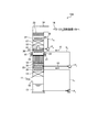
- FIG. 1 is a schematic diagram of a finish flue gas desulfurization apparatus according to a first embodiment.
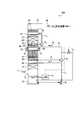
- FIG. 2 is a schematic diagram of a finish flue gas desulfurization apparatus according to a second embodiment.
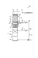
- FIG. 3 is a schematic diagram of a finish flue gas desulfurization apparatus according to a third embodiment.
- FIG. 4 is a schematic diagram of another finish flue gas desulfurization apparatus according to the third embodiment.
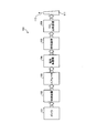
- FIG. 5 is a schematic diagram of an exhaust gas treatment system according to a fourth embodiment.
- FIG. 6 is a diagram illustrating an example of an exhaust gas treatment system.
- FIG. 1 is a schematic diagram of a finish flue gas desulfurization apparatus according to a first embodiment.
- the final flue gas desulfurization apparatus 10A according to the first embodiment removes sulfur oxide from combustion exhaust gas in advance with an existing desulfurization apparatus (not shown), and then reduces the remaining sulfur oxide to an extremely low level.
- a finishing desulfurization apparatus main body (hereinafter referred to as “apparatus main body”) 15 provided with a finishing desulfurization section 14 for desulfurization by bringing the liquid 13 into contact therewith, and a downstream side of the finishing desulfurization section 14 in the finishing desulfurization apparatus main body 15;
- a wet electrostatic precipitator 16 that removes soot and dust in the exhaust gas after the final desulfurization, a cooling unit 17 that cools the exhaust gas, provided in either one of the front and rear of the wet electrostatic precipitator 16, and dust removal and cooling After
- the gas discharge portion 19 for discharging to the outside the combustion exhaust gas (purified gas) 18 is intended to provided.
- the finishing desulfurization section 14 is supplied with lime (CaCO 3 ) absorbing liquid through the circulation line L 1 by the pump P 1 as the absorbing liquid 13 for removing sulfur oxide of the lime gypsum method.
- the wet electrostatic precipitator 16 is supplied with cleaning water 31 for the electrodes through a circulation line L 2 by a pump P 2 .
- the cooling unit 17 is supplied with cooling water 32 through a circulation line L 3 by a pump P 3 .
- Reference numeral 21 denotes an insulator support, 22 an insulator, 23 a mist eliminator, 33 a Jinkasa chimney tray, 34 a distributed chimney tray, and 35 to 37 nozzles.
- the exhaust gas 11 from which sulfur oxide has been removed in advance can be further desulfurized by the finish desulfurization unit 14, and most of the remaining sulfur oxide is removed. can do. Thereafter, the soot can be removed by the wet electrostatic precipitator 16 provided on the upper side of the finish desulfurizer 14.
- the absorbent 13 used in the finish desulfurization unit 14 NaOH, Na 2 CO 3 , NaHCO 3 , Ca (OH) 2 , Mg (OH) 2 and the like can be exemplified in addition to CaCO 3 .
- the cleaning water 31 used in the wet electrostatic precipitator 16 include Na 2 CO 3 and NaHCO 3 in addition to NaOH.
- tanks for supplying the absorbing liquid 13 and the cleaning water 31 are omitted in the drawing.
- the finish desulfurization part 14 and the wet electric dust collection part 16 are made into a similar cross-sectional area (substantially the same cross-sectional structure or a similar cross-sectional structure). This is because, if the structure is greatly widened or expanded, a portion where the gas flow rate is uneven is formed, and the contact efficiency between the exhaust gas and the electrode of the wet dust remover may be lowered, and the dust removal performance may be lowered.
- the preferred gas flow rate of the finish flue gas desulfurization equipment is 2.0 to 3.8 m / s
- the preferred gas flow rate of the wet dust collector is 2.0 to 3.0 m / s.
- a flow rectifying plate is provided at a place where drift in the tower is presumed to occur in advance to suppress gas drift, or a partition-like shape is provided in the finish flue gas desulfurization apparatus having a relatively fast gas flow velocity range.
- a suitable gas flow rate zone may be optimally controlled by providing a jammer plate.
- a suitable gas flow velocity zone for example, 2.5 m / s
- good desulfurization treatment and dust removal treatment may be performed.
- a highly purified purified gas 18 having a sulfur oxide concentration of 10 ppm or less (SO 2 ⁇ 1 to 3 ppm, SO 3 ⁇ 1 to 3 ppm) and a soot concentration of 10 mg / m 3 N or less. can be obtained.
- the cooling unit 17 that cools the exhaust gas is provided on the downstream side of the wet electrostatic precipitator 16, but the present invention is not limited to this, and the upstream side of the wet electrostatic precipitator 16. You may make it provide in (between the finishing desulfurization part 14 and the wet electric dust collection part 16).
- the chimney tray for recovering the cooling water 32 provided at the lower part of the cooling unit 17 either a Jinkasa type chimney tray or a distributed type chimney tray may be used as long as a desired cooling effect can be obtained.
- the chimney tray that collects the washing water 31 in the lower part of the wet electrostatic precipitator 16 is preferably a distributed chimney tray in order to suppress the drift of the exhaust gas.
- the wet electrostatic precipitator 16 is provided on the upper side of the finish desulfurizer 14 so that the removal of soot and dust can be processed at the same time.
- a well-known watering type, jet type, filling type, liquid column type desulfurization apparatus can be used in the finishing desulfurization part 14.
- the exhaust gas 11 is rectified, the rectified gas is supplied to the wet electric dust collection section 16, the contact efficiency with the electrode surface is improved, and the dust collection ability by rectification Will improve.
- the site area can be reduced by integrating the finish desulfurization section and the wet electric dust collection section.
- a connecting duct is required. At this time, when exhaust gas flows in through the connecting duct, it is necessary to connect with a bent duct or the like. Yes, as a result, drift occurs, and the dust removal performance in the wet dust collector decreases.
- this can be solved by using an integrated type.
- the liquid desulfurization apparatus when used in the final desulfurization section 14, for example, 200A to 350A spray pipes are arranged at a pitch of about 0.5 m.
- this functions as a gas rectifying resistance structure, and the liquid falling to the pipe also contributes to resistance pressure loss. It will be.
- the gas rectifying resistance effect in the finish desulfurization section 14 due to the gas rectifying resistance effect in the finish desulfurization section 14, the drift of the gas introduced into the wet electrostatic precipitator 16 integrated in the upper part is suppressed. As a result, the dust collection performance in the wet electric dust collection unit 16 can be improved.
- the decarburization equipment is expected to be applied to existing thermal power in addition to new thermal power due to increasing demand for CO 2 reduction.
- the wet electrostatic precipitator 16 and the finish desulfurizer 14 that have been separately provided in the same cross section, it is possible to install a decarburization / dust removal facility, which facilitates application.
- the wet electric dust collector is provided in one stage inside the apparatus main body 15.
- the present invention is not limited to this, and two stages may be provided continuously. Good.
- FIG. 2 is a schematic diagram of a finish flue gas desulfurization apparatus according to a second embodiment.
- the finishing flue gas desulfurization apparatus 10B according to the second embodiment is configured to extract the cleaning water 31 used in the wet electric dust collection unit 16 through the line L 4 in the finishing flue gas desulfurization apparatus 10A according to the first embodiment.
- the cleaning water 31 is supplied into the absorbing liquid (CaCO 3 ) 13 stored on the lower side of the apparatus body 15 as necessary.
- the washing water 31 for example, by using a strong alkali agent such as NaOH, the desulfurization performance can be further improved.
- the cleaning liquid 31 may be supplied while being monitored by the pH meter 41.
- the combustion exhaust gas (exhaust gas) 11 having a sulfur oxide concentration higher than the allowable value is introduced in the gas introduction unit 12, it becomes particularly effective, and the purified combustion exhaust gas (purified gas) in the gas discharge unit 19 is obtained.
- the concentration of sulfur oxide in 18 can be made extremely low.
- FIG. 3 is a schematic diagram of a finish flue gas desulfurization apparatus according to a third embodiment.
- the final flue gas desulfurization apparatus 10 ⁇ / b> C according to the third embodiment is the same as that of the final flue gas desulfurization apparatus 10 ⁇ / b> A according to the first embodiment. It is used as the absorbing liquid of the unit 14 and is shared as the absorbing / cleaning liquid 42. As shown in FIG.
- the dispersive chimney tray 34 that collects the cleaning water 31 provided in the lower stage of the wet electrostatic precipitator 16 is removed, and the cleaning liquid is dropped as it is.
- the first and second orifices 43A and 43B are interposed in the lines L 11 and L 12 in order to set the supply amount of the strong alkaline liquid absorption / cleaning liquid 42 to a desired flow rate.
- the cleaning water that contributes to the cleaning of the electrode in the wet electrostatic precipitator 16 can be used as it is as the absorbent of the finishing desulfurization unit 14.
- both the absorbing liquid in the finishing desulfurization unit 14 and the cleaning liquid in the wet electrostatic precipitator 16 are the same kind of strong alkali and the same concentration, both the cleaning water and the absorbing liquid can be shared and stored. Auxiliary facilities such as tanks and pumps can be shared.
- a purified gas cooling apparatus 45 for cooling purified gas 18 after precision desulfurization and precision dust removal, and a CO 2 recovery apparatus are further provided.
- a portion of the gas introduced into the CO 2 recovering apparatus 106, via a line L 20, is supplied by the fan 46 as the seal gas 47 of the insulator 22 of the wet electrostatic precipitator unit 16 ( ⁇ 1).
- the seal gas 47 is supplied to the insulator chamber in which the insulator 22 is accommodated, and is constantly ventilated inside the wet electrostatic precipitator 16 to prevent the ingress of exhaust gas. This eliminates the need for separately installed seal air fan equipment costs and electricity costs.
- the gas processing amount is about It can be reduced by about 5%.
- FIG. 5 shows a schematic configuration diagram of an exhaust gas treatment system according to an embodiment of the present invention.
- the exhaust gas treatment system 50 according to the fourth embodiment recovers the heat in the gas after removing the NOx removal device 102 that removes nitrogen oxide in the exhaust gas G from the boiler 101, for example.
- the purified gas 18 supplied to the CO 2 recovery device 106 installed on the rear stage side of the final flue gas desulfurization device 10A has a very low concentration of sulfur oxide, and is circulated and used in the CO 2 recovery device 106. Accumulation of sulfur oxides and soot and dust in the CO 2 absorbing liquid (for example, amine absorbing liquid) is reduced, and deterioration can be suppressed. As a result, reduction of CO 2 absorption performance of the CO 2 absorbing liquid due to the deterioration is reduced, it is possible to perform stable recovery of CO 2.
- the CO 2 absorbing liquid for example, amine absorbing liquid
Landscapes
- Engineering & Computer Science (AREA)
- Chemical & Material Sciences (AREA)
- Environmental & Geological Engineering (AREA)
- Health & Medical Sciences (AREA)
- Biomedical Technology (AREA)
- Analytical Chemistry (AREA)
- General Chemical & Material Sciences (AREA)
- Oil, Petroleum & Natural Gas (AREA)
- Chemical Kinetics & Catalysis (AREA)
- Treating Waste Gases (AREA)
- Electrostatic Separation (AREA)
- Compounds Of Alkaline-Earth Elements, Aluminum Or Rare-Earth Metals (AREA)
Abstract
燃焼排ガスから予め既存の脱硫装置により硫黄酸化物を除去した後に、残存する硫黄酸化物を極低濃度までさらに除去する仕上げ排煙脱硫装置であって、微量の硫黄酸化物を含む燃焼排ガス(排ガス)11を導入するガス導入部12を有し、導入した燃焼排ガス11中の硫黄酸化物に吸収液13を接触させて脱硫する仕上げ脱硫部14を備えた脱硫装置本体15と、前記仕上げ脱硫装置本体15内の仕上げ脱硫部14の後流側に設けられ、仕上げ脱硫後の燃焼排ガス中の煤塵を除去する湿式電気集塵部16と、前記湿式電気集塵部16の前後のいずれか一方に設けられ、燃焼排ガスを冷却する冷却部17と、除塵及び冷却後の浄化燃焼排ガス(浄化ガス)18を外部へ排出するガス排出部19とを、具備する。
Description
本発明は、仕上げ排煙脱硫装置及びこれを用いた排ガス処理システムに関する。
排ガス処理システムの一例を図6に示す。図6の排ガス処理システム100に示すように、ボイラ(石炭焚ボイラ)101からの排ガスGは、脱硝装置102で排ガス中の窒素酸化物(NOx)を除去した後、まずエアヒータ103に導かれてボイラに供給される空気を加熱する。その後排ガスGは、乾式の電気集塵機104に導入されて煤塵が除去される。次に、排ガスGは、脱硫装置105に導入されて硫黄酸化物(SOx)が除去される。その後、排ガスGはCO2回収装置106に導入されて、二酸化炭素を除去し、その後煙突111より浄化ガス112が大気に放出される(例えば、特許文献1参照)。
脱硫と脱炭素を同時に処理する方法として種々の提案がある(特許文献2~4)。
しかしながら、脱硫装置105で脱硫した後に、CO2回収装置106を設置する場合、当該CO2回収装置106に許容量を超える硫黄酸化物や煤塵が残存すると、CO2吸収液として例えばアミン系吸収液を用いる場合、CO2吸収液(例えばアミン吸収液)中に蓄積され、或いは当該劣化相当分の吸収液をリクレーミングしたり、新液を補充する際にランニングコストが多く発生する、という問題がある。
そこで、CO2回収装置106内の吸収液を循環させる際に、フィルタを用いて煤塵を除去することが提案されるが、以下のような問題がある。
1) 繊維充填式のカートリッジフィルタで吸収液中の煤塵を除去する場合には、煤塵の除去効率は低いという問題がある。さらに、使用済みのカートリッジフィルタは廃棄物として処分する必要があり、ランニングコストが増大する、という問題がある。
2) 例えばセルロースや珪藻土等をプレコート剤として用い、煤塵を除去するプレコートフィルタで吸収液中の煤塵を除去する場合には、煤塵の除去効率は高いものの、使用済みのカートリッジフィルタは廃棄物として処分する必要があり、ランニングコストが増大する、という問題がある。また、プレコート剤に吸収液が含有されるので、吸収液の損失が発生するという問題がある。
1) 繊維充填式のカートリッジフィルタで吸収液中の煤塵を除去する場合には、煤塵の除去効率は低いという問題がある。さらに、使用済みのカートリッジフィルタは廃棄物として処分する必要があり、ランニングコストが増大する、という問題がある。
2) 例えばセルロースや珪藻土等をプレコート剤として用い、煤塵を除去するプレコートフィルタで吸収液中の煤塵を除去する場合には、煤塵の除去効率は高いものの、使用済みのカートリッジフィルタは廃棄物として処分する必要があり、ランニングコストが増大する、という問題がある。また、プレコート剤に吸収液が含有されるので、吸収液の損失が発生するという問題がある。
よって、予め脱硫装置105で硫黄酸化物が除去された排ガスGに対して、更に排ガス中の対象成分を極低濃度まで浄化できる仕上げ用の脱硫装置の出現が切望されている。
本発明は、前記問題に鑑み、仕上げ排煙脱硫装置及びこれを用いた排ガス処理システムを提供することを課題とする。
上述した課題を解決するための本発明の第1の発明は、燃焼排ガスから硫黄酸化物を除去した後に、残存する硫黄酸化物を極低濃度までさらに除去する仕上げ排煙脱硫装置であって、微量の硫黄酸化物を含む燃焼排ガスを導入するガス導入部を有し、導入した燃焼排ガス中の硫黄酸化物に吸収液を接触させて脱硫する仕上げ脱硫部を備えた仕上げ脱硫装置本体と、前記仕上げ脱硫装置本体内の仕上げ脱硫部の後流側に設けられ、仕上げ脱硫後の燃焼排ガス中の煤塵を除去する湿式電気集塵部と、前記湿式電気集塵部の前後のいずれか一方に設けられ、燃焼排ガスを冷却する冷却部と、除塵及び冷却後の浄化燃焼排ガスを外部へ排出するガス排出部とを、具備することを特徴とする仕上げ排煙脱硫装置にある。
第2の発明は、第1の発明において、前記仕上げ脱硫部の吸収液と、湿式電気集塵部の洗浄液とが各々独立して循環してなり、前記仕上げ脱硫部の吸収液が、石灰吸収液であると共に、前記湿式電気集塵部の洗浄液が強アルカリ液であることを特徴とする仕上げ排煙脱硫装置にある。
第3の発明は、第1の発明において、前記湿式電気集塵部の強アルカリ液の一部を前記仕上げ脱硫部の石灰吸収液に供給してなることを特徴とする仕上げ排煙脱硫装置にある。
第4の発明は、第1の発明において、前記仕上げ脱硫部の吸収液と、湿式電気集塵部の洗浄液が共に同じ種類の強アルカリで且つ同じ濃度の液を用い、これを共用することを特徴とする仕上げ排煙脱硫装置にある。
第5の発明は、第1乃至4のいずれか一つの発明において、前記浄化ガスを冷却する冷却装置を設け、冷却後の浄化燃焼排ガスの一部を湿式電気集塵部の碍子シールガスに用いることを特徴とする仕上げ排煙脱硫装置にある。
第6の発明は、ボイラ等からの排ガス中の窒素酸化物を除去する脱硝装置と、窒素酸化物除去後のガス中の煤塵を除去する集塵機と、除塵後のガス中の硫黄酸化物を除去する脱硫装置と、この脱硫後の排ガス中に残存する硫黄酸化物を極低濃度までさらに除去する第1乃至5のいずれか一つの仕上げ排煙脱硫装置と、浄化ガス中の二酸化炭素を回収するCO2回収装置とを具備することを特徴とする排ガス処理システムにある。
本発明によれば、硫黄酸化物の濃度が極めて少なくなるので、CO2回収装置で用いるCO2吸収液中における硫黄酸化物や煤塵の蓄積が少なくなり、劣化を抑制することができる。
以下、この発明につき図面を参照しつつ詳細に説明する。なお、この実施例によりこの発明が限定されるものではない。また、下記実施例における構成要素には、当業者が容易に想定できるもの、あるいは実質的に同一のものが含まれる。
本発明による実施例に係る仕上げ排煙脱硫装置について、図面を参照して説明する。図1は、実施例1に係る仕上げ排煙脱硫装置の概略図である。
図1に示すように、実施例1に係る仕上げ排煙脱硫装置10Aは、燃焼排ガスから予め既存の脱硫装置(図示せず)により硫黄酸化物を除去した後に、残存する硫黄酸化物を極低濃度までさらに除去する仕上げ排煙脱硫装置であって、微量の硫黄酸化物を含む燃焼排ガス(排ガス)11を導入するガス導入部12を有し、導入した燃焼排ガス11中の硫黄酸化物に吸収液13を接触させて脱硫する仕上げ脱硫部14を備えた仕上げ脱硫装置本体(以下「装置本体」という)15と、前記仕上げ脱硫装置本体15内の仕上げ脱硫部14の後流側に設けられ、仕上げ脱硫後の燃焼排ガス中の煤塵を除去する湿式電気集塵部16と、前記湿式電気集塵部16の前後のいずれか一方に設けられ、燃焼排ガスを冷却する冷却部17と、除塵及び冷却後の浄化燃焼排ガス(浄化ガス)18を外部へ排出するガス排出部19とを、具備するものである。
本実施例では、仕上げ脱硫部14は、石灰石膏法の硫黄酸化物を除去する吸収液13として石灰(CaCO3)吸収液がポンプP1により循環ラインL1を通して供給されている。
また、湿式電気集塵部16は、電極部の洗浄水31がポンプP2により循環ラインL2を通して供給されている。また、冷却部17は、冷却水32がポンプP3により循環ラインL3を通して供給されている。
符号、21は碍子支持部、22は碍子、23はミストエリミネータ、33は陣笠式チムニートレイ、34は分散式チムニートレイ、35~37はノズルを各々図示する。
図1に示すように、実施例1に係る仕上げ排煙脱硫装置10Aは、燃焼排ガスから予め既存の脱硫装置(図示せず)により硫黄酸化物を除去した後に、残存する硫黄酸化物を極低濃度までさらに除去する仕上げ排煙脱硫装置であって、微量の硫黄酸化物を含む燃焼排ガス(排ガス)11を導入するガス導入部12を有し、導入した燃焼排ガス11中の硫黄酸化物に吸収液13を接触させて脱硫する仕上げ脱硫部14を備えた仕上げ脱硫装置本体(以下「装置本体」という)15と、前記仕上げ脱硫装置本体15内の仕上げ脱硫部14の後流側に設けられ、仕上げ脱硫後の燃焼排ガス中の煤塵を除去する湿式電気集塵部16と、前記湿式電気集塵部16の前後のいずれか一方に設けられ、燃焼排ガスを冷却する冷却部17と、除塵及び冷却後の浄化燃焼排ガス(浄化ガス)18を外部へ排出するガス排出部19とを、具備するものである。
本実施例では、仕上げ脱硫部14は、石灰石膏法の硫黄酸化物を除去する吸収液13として石灰(CaCO3)吸収液がポンプP1により循環ラインL1を通して供給されている。
また、湿式電気集塵部16は、電極部の洗浄水31がポンプP2により循環ラインL2を通して供給されている。また、冷却部17は、冷却水32がポンプP3により循環ラインL3を通して供給されている。
符号、21は碍子支持部、22は碍子、23はミストエリミネータ、33は陣笠式チムニートレイ、34は分散式チムニートレイ、35~37はノズルを各々図示する。
本実施例1に係る仕上げ排煙脱硫装置10Aを用いることで、予め硫黄酸化物が除去された排ガス11を更に仕上げ脱硫部14で脱硫することができ、残留している硫黄酸化物を殆ど除去することができる。その後、仕上げ脱硫部14の上部側に設けられた湿式電気集塵部16により煤塵の除去を行うことができる。
ここで、仕上げ脱硫部14で用いる吸収液13としては、CaCO3以外にはNaOH、Na2CO3、NaHCO3、Ca(OH)2、Mg(OH)2等を例示することができる。
また、湿式電気集塵部16で用いる洗浄水31としては、NaOH以外にはNa2CO3、NaHCO3等を例示することができる。
なお、本実施例においては、図面上、吸収液13及び洗浄水31を各々供給するタンクを省略している。
また、湿式電気集塵部16で用いる洗浄水31としては、NaOH以外にはNa2CO3、NaHCO3等を例示することができる。
なお、本実施例においては、図面上、吸収液13及び洗浄水31を各々供給するタンクを省略している。
また、仕上げ脱硫部14と湿式電気集塵部16とは、類似断面積(略同一の断面構造又は類似断面構造)とするのが好ましい。
これは、大幅な拡幅や拡小構造とすると、ガス流速が偏る部分が出来、排ガスと湿式除塵装置の電極の接触効率が低下して除塵性能が低下する場合があるからである。
これは、大幅な拡幅や拡小構造とすると、ガス流速が偏る部分が出来、排ガスと湿式除塵装置の電極の接触効率が低下して除塵性能が低下する場合があるからである。
また仕上げ排煙脱硫装置の好適ガス流速は2.0~3.8m/s、湿式集塵部の好適ガス流速は2.0~3.0m/sと両者は類似しているが、類似断面構造とする為には両者を通過するガス流速を2.0~3.0m/sの範囲で合わせるのが好ましい。また、必要に応じて塔内の偏流が生じることが事前に想定される箇所に整流板を設けてガス偏流を抑制したり、比較的ガス流速域の速い仕上げ排煙脱硫装置内に隔壁状のジャマ板を設けたりして、好適ガス流速帯を最適に制御するようにしてもよい。
例えば、比較的ガス流速域の速い(例えば3.0m/s程度)流速で排ガス11を仕上げ脱硫部14内に供給する際、仕上げ排煙脱硫装置内に隔壁状のジャマ板を設けることで、後段側の湿式電気集塵部16の好適ガス流速帯(例えば2.5m/s)を最適に制御することができ、この結果良好な脱硫処理と除塵処理とを行うようにしてもよい。
例えば、比較的ガス流速域の速い(例えば3.0m/s程度)流速で排ガス11を仕上げ脱硫部14内に供給する際、仕上げ排煙脱硫装置内に隔壁状のジャマ板を設けることで、後段側の湿式電気集塵部16の好適ガス流速帯(例えば2.5m/s)を最適に制御することができ、この結果良好な脱硫処理と除塵処理とを行うようにしてもよい。
その結果、ガス排出部19では、硫黄酸化物濃度で10ppm以下(SO2<1~3ppm、SO3<1~3ppm)、煤塵濃度で10mg/m3N以下の極めて清浄化された浄化ガス18を得ることができる。
よって、仕上げ排煙脱硫装置10Aの後段側に設置されるCO2回収装置106に浄化ガス18を供給した場合でも、硫黄酸化物の濃度が極めて少なくなるので、CO2吸収液(例えばアミン吸収液)中における蓄積が少なくなる。
この結果、CO2吸収液が劣化に起因するCO2吸収性能の低下を抑制できる。
この結果、CO2吸収液が劣化に起因するCO2吸収性能の低下を抑制できる。
本実施例では、湿式電気集塵部16の後段側に、排ガスを冷却する冷却部17を設けているが、本発明はこれに限定されることはなく、湿式電気集塵部16の前段側(仕上げ脱硫部14と湿式電気集塵部16との間)に設けるようにしてもよい。
なお、冷却部17の下部に設けた冷却水32を回収するチムニートレイは、所望の冷却効果が得られることができれば、陣笠式チムニートレイや分散式チムニートレイのいずれを用いてもよい。但し湿式電気集塵部16の下部の洗浄水31を回収するチムニートレイは、排ガスの偏流を抑制させるために、分散式チムニートレイとするのがよい。
なお、冷却部17の下部に設けた冷却水32を回収するチムニートレイは、所望の冷却効果が得られることができれば、陣笠式チムニートレイや分散式チムニートレイのいずれを用いてもよい。但し湿式電気集塵部16の下部の洗浄水31を回収するチムニートレイは、排ガスの偏流を抑制させるために、分散式チムニートレイとするのがよい。
本実施例によれば、仕上げ脱硫部14の上部側に湿式電気集塵部16を設け、脱硫と共に煤塵の除去を一度に処理することができる。
また、仕上げ脱硫部14においては、公知の散水式、噴流式、充填式、液柱式の脱硫装置を用いることができる。この仕上げ脱硫部14を通過することで、排ガス11が整流化され、湿式電気集塵部16に整流化されたガスが供給され、電極表面との接触効率が良好となり、整流化による集塵能力が向上する。
また、仕上げ脱硫部14においては、公知の散水式、噴流式、充填式、液柱式の脱硫装置を用いることができる。この仕上げ脱硫部14を通過することで、排ガス11が整流化され、湿式電気集塵部16に整流化されたガスが供給され、電極表面との接触効率が良好となり、整流化による集塵能力が向上する。
また、仕上げ脱硫部と湿式電気集塵部との一体型により、敷地面積の低減を図ることができる。
なお、従来の湿式除塵装置は、他設備とは分離して設置されるため、取合いダクトが必要となるが、このとき取合いダクトを介して排ガスを流入する際、曲がりダクト等により連結する必要があり、この結果偏流が生じ、湿式集塵装置での除塵性能が低下するが、一体型とすることで、これを解消することができる。
なお、従来の湿式除塵装置は、他設備とは分離して設置されるため、取合いダクトが必要となるが、このとき取合いダクトを介して排ガスを流入する際、曲がりダクト等により連結する必要があり、この結果偏流が生じ、湿式集塵装置での除塵性能が低下するが、一体型とすることで、これを解消することができる。
ここで、本実施例において、仕上げ脱硫部14において、液柱式の脱硫装置とする場合には、例えば200A~350Aのスプレーパイプが0.5m程度のピッチで配置するようにしている。
このようなスプレーパイプが0.5m程度のピッチで配置されている液柱式の脱硫装置とすることで、これがガス整流抵抗構造体として働き、更に該パイプへの降液も抵抗圧損として寄与することとなる。
このため本一体構造設備では、仕上げ脱硫部14でのガス整流抵抗効果によって、上部に一体化された湿式電気集塵部16に導入するガスの偏流が抑制されることとなる。この結果、湿式電気集塵部16での集塵性能を向上させる事ができることとなる。
このようなスプレーパイプが0.5m程度のピッチで配置されている液柱式の脱硫装置とすることで、これがガス整流抵抗構造体として働き、更に該パイプへの降液も抵抗圧損として寄与することとなる。
このため本一体構造設備では、仕上げ脱硫部14でのガス整流抵抗効果によって、上部に一体化された湿式電気集塵部16に導入するガスの偏流が抑制されることとなる。この結果、湿式電気集塵部16での集塵性能を向上させる事ができることとなる。
脱炭設備は、CO2削減要求の高まりにより新設火力の他に既設火力への適用も多く期待されている事から、特に既設の場合は敷地面積制約により設置成否が左右される場合があるが、この時、従来別置きしていた湿式電気集塵部16と仕上げ脱硫部14とを同一断面で組み合わせる事で脱炭・除塵設備の設置が可能になり、適用が容易となる。
以上の実施例では、湿式電気集塵部を装置本体15の内部に1段設けたものを説明したが、本発明はこれに限定されるものではなく、2段連続して設けるようにしてもよい。
本発明による実施例に係る仕上げ排煙脱硫装置について、図面を参照して説明する。図2は、実施例2に係る仕上げ排煙脱硫装置の概略図である。
図2に示すように、実施例2に係る仕上げ排煙脱硫装置10Bは、実施例1に係る仕上げ排煙脱硫装置10Aにおいて、湿式電気集塵部16で用いる洗浄水31をラインL4により抜き出し、必要に応じて装置本体15の下部側に貯留する吸収液(CaCO3)13中に洗浄水31を供給するようにしている。洗浄水31としては、例えばNaOH等の強アルカリ剤を用いることで、脱硫性能の向上をさらに図ることができる。
なお、洗浄液31の供給は、pH計41で監視しつつ行うようにすればよい。
特に、ガス導入部12において硫黄酸化物の濃度が許容値よりも高いような燃焼排ガス(排ガス)11を導入する場合には、特に有効となり、ガス排出部19での浄化燃焼排ガス(浄化ガス)18中での硫黄酸化物の濃度を極低濃度とすることができる。
図2に示すように、実施例2に係る仕上げ排煙脱硫装置10Bは、実施例1に係る仕上げ排煙脱硫装置10Aにおいて、湿式電気集塵部16で用いる洗浄水31をラインL4により抜き出し、必要に応じて装置本体15の下部側に貯留する吸収液(CaCO3)13中に洗浄水31を供給するようにしている。洗浄水31としては、例えばNaOH等の強アルカリ剤を用いることで、脱硫性能の向上をさらに図ることができる。
なお、洗浄液31の供給は、pH計41で監視しつつ行うようにすればよい。
特に、ガス導入部12において硫黄酸化物の濃度が許容値よりも高いような燃焼排ガス(排ガス)11を導入する場合には、特に有効となり、ガス排出部19での浄化燃焼排ガス(浄化ガス)18中での硫黄酸化物の濃度を極低濃度とすることができる。
これは、一般に、石灰石膏法とNaOH等の強アルカリ脱硫法の性能を相当モル量で比較した場合、後者は液側境膜抵抗がない為に脱硫性能が高くなるので、仕上げ脱硫部14に強アルカリ(例えばNaOH)を加えた場合も性能の向上に寄与することとなる。
本発明による実施例に係る仕上げ排煙脱硫装置について、図面を参照して説明する。図3は、実施例3に係る仕上げ排煙脱硫装置の概略図である。
図3に示すように、実施例3に係る仕上げ排煙脱硫装置10Cは、実施例1に係る仕上げ排煙脱硫装置10Aにおいて、湿式電気集塵部16で用いる洗浄液の強アルカリ液を、仕上げ脱硫部14の吸収液として用いて、吸収・洗浄液42として共用するものである。
図3に示すように、実施例1の仕上げ排煙脱硫装置10Aにおいて、湿式電気集塵部16の下段に設けた洗浄水31を回収する分散式チムニートレイ34を取り除き、洗浄液はそのまま落下して、吸収液として機能するようにしている。
なお、強アルカリ液の吸収・洗浄液42の供給量を所望の流量とするために、ラインL11、L12には第1及び第2のオリフィス43A、43Bが各々介装されている。
図3に示すように、実施例3に係る仕上げ排煙脱硫装置10Cは、実施例1に係る仕上げ排煙脱硫装置10Aにおいて、湿式電気集塵部16で用いる洗浄液の強アルカリ液を、仕上げ脱硫部14の吸収液として用いて、吸収・洗浄液42として共用するものである。
図3に示すように、実施例1の仕上げ排煙脱硫装置10Aにおいて、湿式電気集塵部16の下段に設けた洗浄水31を回収する分散式チムニートレイ34を取り除き、洗浄液はそのまま落下して、吸収液として機能するようにしている。
なお、強アルカリ液の吸収・洗浄液42の供給量を所望の流量とするために、ラインL11、L12には第1及び第2のオリフィス43A、43Bが各々介装されている。
これにより、湿式電気集塵部16で電極の洗浄に寄与した洗浄水をそのまま、仕上げ脱硫部14の吸収液として用いることができる。
また、前記仕上げ脱硫部14の吸収液と、湿式電気集塵部16の洗浄液とが共に同じ種類の強アルカリで且つ同じ濃度の液を用いるので、両者の洗浄水と吸収液を共用でき、貯留タンクやポンプ等の付帯設備の共有化を図ることができる。
また、前記仕上げ脱硫部14の吸収液と、湿式電気集塵部16の洗浄液とが共に同じ種類の強アルカリで且つ同じ濃度の液を用いるので、両者の洗浄水と吸収液を共用でき、貯留タンクやポンプ等の付帯設備の共有化を図ることができる。
また、本実施例では、仕上げ脱硫部14の吸収液として、NaOH等の強アルカリ液のみを用いているので、石灰石膏法に較べて、液側境膜抵抗がないために、脱硫性能が高くなり、ガス導入部12における硫黄酸化物の濃度が高いような場合であっても、良好な脱硫性能を発揮することとなり、ガス排出部19での浄化ガス18中の硫黄酸化物濃度が1ppm以下の精密脱硫に大きく寄与することとなる。
また、図4に示すように、実施例3の他の仕上げ排煙脱硫装置10Dにおいては、更に、精密脱硫、精密除塵後の浄化ガス18を冷却する浄化ガス冷却装置45と、CO2回収装置106とを設ける際、CO2回収装置106に導入する一部のガスを、ラインL20を介して、湿式電気集塵部16の碍子22のシールガス47としてファン46により供給している(※1)。すなわち、碍子22が収納される碍子室にシールガス47を供給して、常に湿式電気集塵部16の内部に通気することで、排ガスの浸入を防止するようにしている。
これによって、別途設けるシールエアファン設備費・電気費が不要となる。さらに、排ガスの一部を循環させることとなるので、自己ガスシールとなり、CO2回収装置でのトータルの排ガス処理量を従来の空気で賄っていた際と比較して、ガス処理量を例えば約5%程度低減することができる。
これによって、別途設けるシールエアファン設備費・電気費が不要となる。さらに、排ガスの一部を循環させることとなるので、自己ガスシールとなり、CO2回収装置でのトータルの排ガス処理量を従来の空気で賄っていた際と比較して、ガス処理量を例えば約5%程度低減することができる。
本発明による実施例に係る排ガス処理システムの概略構成図を図5に示す。
図5に示すように、実施例4に係る排ガス処理システム50は、例えばボイラ101からの排ガスG中の窒素酸化物を除去する脱硝装置102と、窒素酸化物除去後のガス中の熱を回収するエアヒータ103と、熱回収後のガス中の煤塵を除去する電気集塵機104と、除塵後のガス中の硫黄酸化物を除去する脱硫装置105と、この脱硫後の排ガス11中に残存する硫黄酸化物を極低濃度までさらに除去する実施例1に係る仕上げ脱硫装置10Aと、浄化ガス18中の二酸化炭素を回収するCO2回収装置106と、CO2回収後のガス112を外部に排出する煙突111とを具備するものである。
図5に示すように、実施例4に係る排ガス処理システム50は、例えばボイラ101からの排ガスG中の窒素酸化物を除去する脱硝装置102と、窒素酸化物除去後のガス中の熱を回収するエアヒータ103と、熱回収後のガス中の煤塵を除去する電気集塵機104と、除塵後のガス中の硫黄酸化物を除去する脱硫装置105と、この脱硫後の排ガス11中に残存する硫黄酸化物を極低濃度までさらに除去する実施例1に係る仕上げ脱硫装置10Aと、浄化ガス18中の二酸化炭素を回収するCO2回収装置106と、CO2回収後のガス112を外部に排出する煙突111とを具備するものである。
よって、仕上げ排煙脱硫装置10Aの後段側に設置されるCO2回収装置106に供給される浄化ガス18は、硫黄酸化物の濃度が極めて少なくなるので、CO2回収装置106で循環して利用されるCO2吸収液(例えばアミン吸収液)中における硫黄酸化物や煤塵の蓄積が少なくなり、劣化を抑制することができる。
この結果、CO2吸収液が劣化に起因するCO2吸収性能の低下が少なくなり、安定してCO2の回収を行うことができる。
この結果、CO2吸収液が劣化に起因するCO2吸収性能の低下が少なくなり、安定してCO2の回収を行うことができる。
また、CO2吸収性能の低下を補うために、CO2吸収性能の追加供給の回数と供給量が少なくなると共に、CO2吸収性能の回復のためのリクレーミング頻度の増大がなくなり、排ガス処理システムにおけるランニングコストの削減を図ることができる。
10A~10D 仕上げ排煙脱硫装置
11 微量の硫黄酸化物を含む燃焼排ガス(排ガス)
12 ガス導入部
13 吸収液
14 仕上げ脱硫部
15 仕上げ脱硫装置本体(装置本体)
16 湿式電気集塵部
17 冷却部
18 浄化燃焼排ガス(浄化ガス)
19 ガス排出部
50 排ガス処理システム
101 ボイラ
102 脱硝装置
103 エアヒータ
104 電気集塵機
105 脱硫装置
106 CO2回収装置
111 煙突
G 排ガス
11 微量の硫黄酸化物を含む燃焼排ガス(排ガス)
12 ガス導入部
13 吸収液
14 仕上げ脱硫部
15 仕上げ脱硫装置本体(装置本体)
16 湿式電気集塵部
17 冷却部
18 浄化燃焼排ガス(浄化ガス)
19 ガス排出部
50 排ガス処理システム
101 ボイラ
102 脱硝装置
103 エアヒータ
104 電気集塵機
105 脱硫装置
106 CO2回収装置
111 煙突
G 排ガス
Claims (6)
- 燃焼排ガスから硫黄酸化物を除去した後に、残存する硫黄酸化物を極低濃度までさらに除去する仕上げ排煙脱硫装置であって、
微量の硫黄酸化物を含む燃焼排ガスを導入するガス導入部を有し、導入した燃焼排ガス中の硫黄酸化物に吸収液を接触させて脱硫する仕上げ脱硫部を備えた仕上げ脱硫装置本体と、
前記仕上げ脱硫装置本体内の仕上げ脱硫部の後流側に設けられ、仕上げ脱硫後の燃焼排ガス中の煤塵を除去する湿式電気集塵部と、
前記湿式電気集塵部の前後のいずれか一方に設けられ、燃焼排ガスを冷却する冷却部と、
除塵及び冷却後の浄化燃焼排ガスを外部へ排出するガス排出部とを、具備することを特徴とする仕上げ排煙脱硫装置。 - 請求項1において、
前記仕上げ脱硫部の吸収液と、湿式電気集塵部の洗浄液とが各々独立して循環してなり、
前記仕上げ脱硫部の吸収液が、石灰吸収液であると共に、
前記湿式電気集塵部の洗浄液が強アルカリ液であることを特徴とする仕上げ排煙脱硫装置。 - 請求項1において、
前記湿式電気集塵部の強アルカリ液の一部を前記仕上げ脱硫部の石灰吸収液に供給してなることを特徴とする仕上げ排煙脱硫装置。 - 請求項1において、
前記仕上げ脱硫部の吸収液と、湿式電気集塵部の洗浄液とが共に同じ種類の強アルカリで且つ同じ濃度の液を用い、これを共用することを特徴とする仕上げ排煙脱硫装置。 - 請求項1乃至4のいずれか一つにおいて、
前記浄化燃焼排ガスを冷却する冷却装置を設け、冷却後の浄化ガスの一部を湿式電気集塵部の碍子シールガスに用いることを特徴とする仕上げ排煙脱硫装置。 - ボイラ等からの排ガス中の窒素酸化物を除去する脱硝装置と、窒素酸化物除去後のガス中の煤塵を除去する集塵機と、除塵後のガス中の硫黄酸化物を除去する脱硫装置と、この脱硫後の排ガス中に残存する硫黄酸化物を極低濃度までさらに除去する請求項1乃至5のいずれか一つの仕上げ排煙脱硫装置と、浄化ガス中の二酸化炭素を回収するCO2回収装置とを具備することを特徴とする排ガス処理システム。
Applications Claiming Priority (2)
| Application Number | Priority Date | Filing Date | Title |
|---|---|---|---|
| JP2010045905A JP5705443B2 (ja) | 2010-03-02 | 2010-03-02 | 仕上げ排煙脱硫装置及びこれを用いた排ガス処理システム |
| JP2010-045905 | 2010-03-02 |
Publications (1)
| Publication Number | Publication Date |
|---|---|
| WO2011108324A1 true WO2011108324A1 (ja) | 2011-09-09 |
Family
ID=44541992
Family Applications (1)
| Application Number | Title | Priority Date | Filing Date |
|---|---|---|---|
| PCT/JP2011/051947 Ceased WO2011108324A1 (ja) | 2010-03-02 | 2011-01-31 | 仕上げ排煙脱硫装置及びこれを用いた排ガス処理システム |
Country Status (2)
| Country | Link |
|---|---|
| JP (1) | JP5705443B2 (ja) |
| WO (1) | WO2011108324A1 (ja) |
Cited By (5)
| Publication number | Priority date | Publication date | Assignee | Title |
|---|---|---|---|---|
| CN102688682A (zh) * | 2012-05-16 | 2012-09-26 | 浙江菲达环保科技股份有限公司 | 一种烟气脱硫塔 |
| JP2015127046A (ja) * | 2013-12-30 | 2015-07-09 | シャンハイ クライド ベルゲマン マシナリー カンパニー リミテッド | 煙道ガス処理装置 |
| CN105903337A (zh) * | 2016-06-21 | 2016-08-31 | 南通亚泰工程技术有限公司 | 一种烟气脱硫提效、除尘、脱水一体化装置 |
| US9839916B2 (en) | 2012-07-20 | 2017-12-12 | Mitsubishi Hitachi Power Systems Environmental Solutions, Ltd. | Wet-type electric dust collection device and dust removal method |
| WO2023199662A1 (ja) | 2022-04-15 | 2023-10-19 | 三菱重工業株式会社 | 集塵システム及び集塵方法 |
Families Citing this family (8)
| Publication number | Priority date | Publication date | Assignee | Title |
|---|---|---|---|---|
| US9492786B2 (en) | 2011-11-22 | 2016-11-15 | Fluor Corporation | Multi-purpose absorber |
| US8545782B1 (en) * | 2012-10-16 | 2013-10-01 | Mitsubishi Heavy Industries, Ltd. | CO2 recovery apparatus and CO2 recovery method |
| CN104014229A (zh) * | 2014-06-20 | 2014-09-03 | 北京中冶隆生环保科技发展有限公司 | 烟气多级涡轮增压湍流湿法同时脱硫脱硝装置及使用方法 |
| CN104028096A (zh) * | 2014-06-20 | 2014-09-10 | 北京中冶隆生环保科技发展有限公司 | 烟气增压湍流湿法脱硝及脱硝废液回用技术 |
| CN104324602B (zh) * | 2014-10-29 | 2016-05-25 | 鞍山红拖机械制造股份有限公司 | 一种烟尘废气污染源控制装置及工艺方法 |
| CN105214847A (zh) * | 2015-10-13 | 2016-01-06 | 佛山市博顿空气科技有限公司 | 餐饮油烟净化机电场自动清洗系统 |
| CN107684810A (zh) * | 2017-09-06 | 2018-02-13 | 河北环科力创环境工程有限公司 | 烟气超低排放装置及使用方法 |
| CN112547308B (zh) * | 2020-11-24 | 2023-04-18 | 临沂绿楠环保科技有限公司 | 一种工业湿式电除尘器 |
Citations (5)
| Publication number | Priority date | Publication date | Assignee | Title |
|---|---|---|---|---|
| JPS53111579A (en) * | 1977-03-10 | 1978-09-29 | Ebara Corp | Method of and for preventing creation of dew on insulators of electric dust collector |
| JPH07155537A (ja) * | 1993-12-08 | 1995-06-20 | Kansai Electric Power Co Inc:The | 高性能排ガス処理方法及び装置 |
| JPH11137954A (ja) * | 1997-11-10 | 1999-05-25 | Mitsubishi Heavy Ind Ltd | 重質油焚ボイラ排ガスの処理装置 |
| JP2001289430A (ja) * | 2000-04-06 | 2001-10-19 | Ishikawajima Harima Heavy Ind Co Ltd | 排ガス処理装置 |
| JP2009226367A (ja) * | 2008-03-25 | 2009-10-08 | Chiyoda Kako Kensetsu Kk | 脱硫脱炭装置および二酸化炭素除去方法 |
-
2010
- 2010-03-02 JP JP2010045905A patent/JP5705443B2/ja active Active
-
2011
- 2011-01-31 WO PCT/JP2011/051947 patent/WO2011108324A1/ja not_active Ceased
Patent Citations (5)
| Publication number | Priority date | Publication date | Assignee | Title |
|---|---|---|---|---|
| JPS53111579A (en) * | 1977-03-10 | 1978-09-29 | Ebara Corp | Method of and for preventing creation of dew on insulators of electric dust collector |
| JPH07155537A (ja) * | 1993-12-08 | 1995-06-20 | Kansai Electric Power Co Inc:The | 高性能排ガス処理方法及び装置 |
| JPH11137954A (ja) * | 1997-11-10 | 1999-05-25 | Mitsubishi Heavy Ind Ltd | 重質油焚ボイラ排ガスの処理装置 |
| JP2001289430A (ja) * | 2000-04-06 | 2001-10-19 | Ishikawajima Harima Heavy Ind Co Ltd | 排ガス処理装置 |
| JP2009226367A (ja) * | 2008-03-25 | 2009-10-08 | Chiyoda Kako Kensetsu Kk | 脱硫脱炭装置および二酸化炭素除去方法 |
Cited By (6)
| Publication number | Priority date | Publication date | Assignee | Title |
|---|---|---|---|---|
| CN102688682A (zh) * | 2012-05-16 | 2012-09-26 | 浙江菲达环保科技股份有限公司 | 一种烟气脱硫塔 |
| US9839916B2 (en) | 2012-07-20 | 2017-12-12 | Mitsubishi Hitachi Power Systems Environmental Solutions, Ltd. | Wet-type electric dust collection device and dust removal method |
| JP2015127046A (ja) * | 2013-12-30 | 2015-07-09 | シャンハイ クライド ベルゲマン マシナリー カンパニー リミテッド | 煙道ガス処理装置 |
| US9782782B2 (en) | 2013-12-30 | 2017-10-10 | Shanghai Clyde Bergemann Machinery Co., Ltd. | Flue gas treatment device |
| CN105903337A (zh) * | 2016-06-21 | 2016-08-31 | 南通亚泰工程技术有限公司 | 一种烟气脱硫提效、除尘、脱水一体化装置 |
| WO2023199662A1 (ja) | 2022-04-15 | 2023-10-19 | 三菱重工業株式会社 | 集塵システム及び集塵方法 |
Also Published As
| Publication number | Publication date |
|---|---|
| JP2011177674A (ja) | 2011-09-15 |
| JP5705443B2 (ja) | 2015-04-22 |
Similar Documents
| Publication | Publication Date | Title |
|---|---|---|
| JP5705443B2 (ja) | 仕上げ排煙脱硫装置及びこれを用いた排ガス処理システム | |
| JP6045653B2 (ja) | Co2吸収液の飛散抑制方法 | |
| CA2801291C (en) | Air pollution control system and method | |
| JP5416679B2 (ja) | 排ガス処理方法と装置 | |
| CA2801169C (en) | Air pollution control system and method | |
| JP2015211969A (ja) | 排ガス処理システム及び方法 | |
| EP2537574B1 (en) | Air pollution control system and air pollution control method | |
| US8668889B2 (en) | Air pollution control system and method | |
| JP2011177674A5 (ja) | ||
| JP2010115602A (ja) | 湿式二段脱硫方法と装置 | |
| JP2013039511A (ja) | 湿式排煙脱硫装置およびそれを備えた火力発電プラント | |
| WO2011152546A1 (ja) | 排ガス処理システム及び方法 | |
| JP5144967B2 (ja) | 排ガス処理システム | |
| JP5859244B2 (ja) | 排煙処理設備と排煙処理方法 | |
| KR20080090359A (ko) | 탈질율과 열효율이 향상되는 보일러 시스템 | |
| CN203303814U (zh) | 用于烟气处理的除雾除尘装置以及烟气除雾除尘系统 | |
| CN104785094A (zh) | 锅炉烟气一体化脱硫除尘装置 | |
| CN204853524U (zh) | 一种脱硫除尘设备 | |
| JP2014121685A (ja) | 排ガス処理装置 | |
| JP2008062205A (ja) | ガス浄化装置、排煙脱硫システム、排ガス処理方法 | |
| EP3499121A1 (en) | Boiler equipment and operation method therefor | |
| CN202315669U (zh) | 多污染物烟气全面净化一体化装置 | |
| JP2008080261A (ja) | 排ガス処理方法 | |
| WO2016175163A1 (ja) | ガスクーラの洗浄排水処理方法と装置 | |
| JPS62176517A (ja) | 高炉・炉頂圧乾式発電における腐食性ガス除去システム |
Legal Events
| Date | Code | Title | Description |
|---|---|---|---|
| 121 | Ep: the epo has been informed by wipo that ep was designated in this application |
Ref document number: 11750437 Country of ref document: EP Kind code of ref document: A1 |
|
| NENP | Non-entry into the national phase |
Ref country code: DE |
|
| 122 | Ep: pct application non-entry in european phase |
Ref document number: 11750437 Country of ref document: EP Kind code of ref document: A1 |