WO2011108146A1 - 画像符号化装置、画像符号化復号化システム、画像符号化方法、画像表示方法 - Google Patents
画像符号化装置、画像符号化復号化システム、画像符号化方法、画像表示方法 Download PDFInfo
- Publication number
- WO2011108146A1 WO2011108146A1 PCT/JP2010/069939 JP2010069939W WO2011108146A1 WO 2011108146 A1 WO2011108146 A1 WO 2011108146A1 JP 2010069939 W JP2010069939 W JP 2010069939W WO 2011108146 A1 WO2011108146 A1 WO 2011108146A1
- Authority
- WO
- WIPO (PCT)
- Prior art keywords
- intra
- image
- data
- picture
- encoded data
- Prior art date
Links
Images


Classifications
-
- H—ELECTRICITY
- H04—ELECTRIC COMMUNICATION TECHNIQUE
- H04N—PICTORIAL COMMUNICATION, e.g. TELEVISION
- H04N19/00—Methods or arrangements for coding, decoding, compressing or decompressing digital video signals
- H04N19/60—Methods or arrangements for coding, decoding, compressing or decompressing digital video signals using transform coding
- H04N19/61—Methods or arrangements for coding, decoding, compressing or decompressing digital video signals using transform coding in combination with predictive coding
-
- H—ELECTRICITY
- H04—ELECTRIC COMMUNICATION TECHNIQUE
- H04N—PICTORIAL COMMUNICATION, e.g. TELEVISION
- H04N19/00—Methods or arrangements for coding, decoding, compressing or decompressing digital video signals
- H04N19/10—Methods or arrangements for coding, decoding, compressing or decompressing digital video signals using adaptive coding
- H04N19/102—Methods or arrangements for coding, decoding, compressing or decompressing digital video signals using adaptive coding characterised by the element, parameter or selection affected or controlled by the adaptive coding
- H04N19/115—Selection of the code volume for a coding unit prior to coding
-
- H—ELECTRICITY
- H04—ELECTRIC COMMUNICATION TECHNIQUE
- H04N—PICTORIAL COMMUNICATION, e.g. TELEVISION
- H04N19/00—Methods or arrangements for coding, decoding, compressing or decompressing digital video signals
- H04N19/10—Methods or arrangements for coding, decoding, compressing or decompressing digital video signals using adaptive coding
- H04N19/134—Methods or arrangements for coding, decoding, compressing or decompressing digital video signals using adaptive coding characterised by the element, parameter or criterion affecting or controlling the adaptive coding
- H04N19/157—Assigned coding mode, i.e. the coding mode being predefined or preselected to be further used for selection of another element or parameter
- H04N19/159—Prediction type, e.g. intra-frame, inter-frame or bidirectional frame prediction
-
- H—ELECTRICITY
- H04—ELECTRIC COMMUNICATION TECHNIQUE
- H04N—PICTORIAL COMMUNICATION, e.g. TELEVISION
- H04N19/00—Methods or arrangements for coding, decoding, compressing or decompressing digital video signals
- H04N19/10—Methods or arrangements for coding, decoding, compressing or decompressing digital video signals using adaptive coding
- H04N19/169—Methods or arrangements for coding, decoding, compressing or decompressing digital video signals using adaptive coding characterised by the coding unit, i.e. the structural portion or semantic portion of the video signal being the object or the subject of the adaptive coding
- H04N19/17—Methods or arrangements for coding, decoding, compressing or decompressing digital video signals using adaptive coding characterised by the coding unit, i.e. the structural portion or semantic portion of the video signal being the object or the subject of the adaptive coding the unit being an image region, e.g. an object
- H04N19/176—Methods or arrangements for coding, decoding, compressing or decompressing digital video signals using adaptive coding characterised by the coding unit, i.e. the structural portion or semantic portion of the video signal being the object or the subject of the adaptive coding the unit being an image region, e.g. an object the region being a block, e.g. a macroblock
Definitions
- the present invention relates to an image encoding device, an image encoding / decoding system, an image encoding method, and an image display method.
- H.264 As a video encoding method, for example, H.264 is used.
- H.264, MPEG (Moving Picture Experts Group) -2, MPEG-4, and the like are known.
- data compression is often performed at the time of encoding.
- encoding and “compression encoding” may be used synonymously.
- the present specification basically uses the same terms.
- Intra coding is a technique for coding a picture that constitutes a moving picture using only that picture regardless of other pictures. Therefore, an intra-coded picture (hereinafter also referred to as an intra-coded picture) can be decoded alone. Note that an intra-coded picture is also referred to as an I picture (Intra-Picture).
- inter coding is a method of performing inter prediction (also referred to as inter-picture prediction, inter-picture prediction, etc.) using correlation with other pictures, and encoding the prediction result, that is, a predicted picture. is there.
- Inter prediction may be performed between predicted pictures for other pictures.
- An inter-encoded picture (hereinafter also referred to as an inter-encoded picture) cannot be decoded unless a picture (referred to as a reference picture or a reference screen) referred to at the time of inter prediction is used.
- the inter-coded pictures include a P picture (Predictive-Picture) coded based on the front picture in the moving image sequence and a B picture (Bidirectional) coded based on the front and rear pictures.
- P picture Predictive-Picture
- B picture Bidirectional coded based on the front and rear pictures.
- predictive-picture There are two types: predictive-picture.
- intra coding a picture to be coded is divided into a plurality of blocks (or macro blocks), and is also referred to as intra prediction (intra-screen prediction, intra-picture prediction, etc.) using the correlation between the blocks. May be performed.
- the amount of encoded data to be generated (in other words, the amount of code) is controlled so as to be within the limits of the communication band of the transmission path (in other words, the transmission rate).
- an intra-coded picture has a larger code amount than an inter-coded picture. For this reason, when the amount of code is reduced in order to meet the above various restrictions, the amount of reduction is larger for intra-coded pictures than for inter-coded pictures.
- the image coding apparatus performs compression coding on image data of each picture constituting an input moving image, and selects either inter-coded data or intra-coded data for each picture.
- a compression encoding unit that performs a predetermined process including a generation process for generating one of them and an output process for outputting the generated encoded data to a wired or wireless transmission path, and the compression encoding unit, Control means for controlling which of the inter-encoded data and the intra-encoded data is to be generated and control of the amount of code generated by the compression encoding;
- the compression encoding means When the compression encoding means generates the inter-encoded data, it is 1 pixel based on the upper limit transmission rate of the transmission path and the picture rate of the input moving picture.
- the maximum code amount is larger than the maximum code amount.
- a code amount equal to or less than N times (N is an integer of 2 or more) is set.
- the image encoding device is the image encoding device according to the first aspect, wherein the compression encoding means performs the predetermined processing on the intra-encoded data, It takes a processing time longer than the allowable time and not more than N times the allowable time.
- An image encoding device is the image encoding device according to the first or second aspect, wherein the compression encoding means includes the picture corresponding to the intra-encoded data. For ⁇ N-1 ⁇ pictures following the above, at least the output processing of the predetermined processing is not performed.
- An image encoding device is the image encoding device according to the third aspect, wherein the compression encoding means is configured to perform the above processing for the ⁇ N-1 ⁇ pictures. The generation process is not performed in the predetermined process.
- the image coding apparatus performs compression coding on the image data of each picture constituting the input moving image, and selects either inter-coded data or intra-coded data for each picture.
- a compression encoding means for performing a predetermined process including a generation process for generating one and an output process for outputting the generated encoded data to a wired or wireless transmission path; and Control means for controlling whether to generate inter-encoded data or intra-encoded data, and controlling the amount of code generated by the compression encoding, the compression encoding
- the means performs the predetermined processing on the intra-coded data more than an allowable time allocated per picture based on a picture rate of the input moving image. Ku N times the allowable time (N is an integer of 2 or more) performed over a period of time following the processing time.
- the image coding apparatus is the image coding apparatus according to the fifth aspect, wherein the compression coding means follows the picture corresponding to the intra-coded data ⁇ The predetermined process is not performed for N-1 ⁇ pictures.
- An image encoding / decoding system includes an image encoding apparatus according to any one of the first to sixth aspects, the image encoding apparatus, and the wired or wireless An image decoding device provided to be communicable via a transmission path, the image decoding device receiving the encoded data from the image encoding device, and based on the encoded data, the compression Decoding means for generating decoded data by performing decoding corresponding to encoding, and output means for sequentially outputting the decoded data sequentially generated by the decoding to a display device
- the output means performs inter decoding corresponding to the inter encoded data received immediately before the intra encoded data until the decoding of the intra encoded data is completed. And it outputs the data to the repeated display device for the.
- the image coding method includes (a) compression coding on image data of each picture constituting the input moving image, and the inter coding data and the intra coding data for each picture.
- the code amount is larger than the maximum code amount.
- a code amount not more than N times the maximum code amount (N is an integer of 2 or more) is set.
- An image encoding method is the image encoding method according to the eighth aspect, wherein in the step (a), the predetermined process for the intra-encoded data is performed by It takes a processing time longer than the allowable time and not more than N times the allowable time.
- the image coding method according to the tenth aspect is the image coding method according to the eighth or ninth aspect, wherein in the step (a), the picture corresponding to the intra-coded data is used. For ⁇ N-1 ⁇ pictures following the above, at least the output processing of the predetermined processing is not performed.
- the image coding method according to the eleventh aspect is the image coding method according to the tenth aspect described above, wherein in the step (a), the ⁇ N-1 ⁇ pictures are The generation process is not performed in the predetermined process.
- the image encoding method includes (a) compression encoding the image data of each picture constituting the input moving image, and the inter encoded data and the intra encoded data for each picture.
- the image coding method according to the thirteenth aspect is the image coding method according to the twelfth aspect described above, and the step (a) follows the picture corresponding to the intra-coded data ⁇
- the predetermined process is not performed for N-1 ⁇ pictures.
- An image display method is the wired or wireless transmission of the encoded data generated by the image encoding method according to any one of the eighth to thirteenth aspects.
- the intra coding is performed in the step (d). Until the decoding of data is completed, the inter-decoded data corresponding to the inter-encoded data received immediately before the intra-encoded data. The performing the image display by using repeatedly.
- the code amount of the intra-coded data is set to be larger than the maximum code amount defined based on the transmission rate of the transmission path. For this reason, the picture quality of a picture obtained by decoding intra-encoded data can be improved as compared with a case where the code amount of intra-encoded data is set to the maximum code amount or less. Furthermore, as a result, the image quality of the entire decoded moving image can be improved.
- intra-encoded data can be generated with a code amount exceeding the maximum code amount, and the intra-encoded data thus increased is transmitted at the transmission rate. It is possible to provide a form capable of completing output to the transmission line while complying with the restrictions. According to such an aspect, it is possible to reduce the processing load on the compression encoding means compared to the case where the predetermined processing for intra-encoded data is terminated within an allowable time per picture. In addition, since the necessity of adopting a high-performance configuration for the compression encoding means is reduced as the processing load is reduced, cost reduction, power saving, and the like can be achieved.
- the ⁇ N-1 ⁇ pictures are thinned out for output to the transmission path, so that the amount of data (code amount) output to the transmission path is suppressed. Can do.
- an allowance time for the ⁇ N-1 ⁇ pictures is also spent for the completion of the output of the increased intra-coded data. Therefore, when the output of the ⁇ N-1 ⁇ pictures is not thinned out, the data output to the transmission path is sequentially delayed, and further, the delay is accumulated every time intra-coded data is output. Will go.
- such output delay and delay accumulation can be prevented.
- the processing amount for the ⁇ N-1 ⁇ pictures is reduced. Thereby, power saving etc. can be achieved.
- the code amount of intra-coded data can be made larger than the maximum code amount that can be generated and output within an allowable time per picture. Therefore, it is possible to improve the picture quality of a picture obtained by decoding the intra-coded data, compared to the case where only the allowable time is assigned to the intra-coded data. Furthermore, as a result, the image quality of the entire decoded moving image can be improved.
- the fifth and twelfth aspects it is possible to reduce the processing load on the compression encoding means compared to the case where the increased amount of intra-encoded data is generated within the allowable time.
- the necessity of adopting a high-performance configuration for the compression encoding means is reduced as the processing load is reduced, cost reduction, power saving, and the like can be achieved.
- the amount of data (code amount) output to the transmission path is suppressed. Can do.
- the data output to the transmission path is sequentially delayed, and the delay is accumulated every time intra-coded data is output. become.
- such output delay and delay accumulation can be prevented.
- the processing amount for the ⁇ N-1 ⁇ pictures is reduced. Thereby, power saving etc. can be achieved.
- the intra-encoded data requires a longer decoding processing time than the inter-encoded data, but until the decoding of the intra-encoded data is completed.
- An image obtained by decoding the immediately preceding inter-coded data is repeatedly displayed. For this reason, it is possible to prevent image loss (for example, an image of a full black display is interrupted) from occurring in the decoded moving image.
- the quality of a moving image can be improved by preventing image loss and further preventing display defects caused by the image loss (for example, the image flickers due to the presence of the image loss).
- FIG. 1 is a block diagram outlining an image encoding / decoding system according to an embodiment of the present invention.
- FIG. It is a figure which outlines the structure of a moving image. It is a block diagram which outlines the image coding apparatus which concerns on embodiment. It is a block diagram which outlines the image coding apparatus which concerns on embodiment. It is a block diagram which outlines the image decoding apparatus which concerns on embodiment (double buffer structure). It is a figure which outlines the management of the storage area in a double buffer structure regarding the image decoding apparatus which concerns on embodiment. It is a figure which outlines operation
- FIG. 1 is a block diagram outlining an image encoding / decoding system 12 according to an embodiment of the present invention.
- the image encoding / decoding system 12 includes an image encoding device 14 and an image decoding device 16.
- the display device 18 is also shown in FIG.
- image encoding / decoding system image encoding device
- image decoding device image decoding device
- the encoding device 14 receives image data 22 of a moving image as input, generates encoded data 24 by encoding the image data 22 according to a predetermined encoding method, and outputs the encoded data 24.
- the input image data 22 (in other words, the original image data 22) is supplied from, for example, a moving image supply source (not shown).
- the decoding device 16 is configured to be capable of wired or wireless communication with the encoding device 14 and acquires encoded data 24 from the encoding device 14.
- the decoding device 16 generates decoded data 26 by decoding the acquired encoded data 24 according to a predetermined decoding method, and outputs the decoded data 26.
- the predetermined decoding method in the decoding device 16 corresponds to the predetermined encoding method in the encoding device 14. In other words, both systems conform to the same or compatible encoding / decoding scheme.
- an encoding / decoding method for example, H.264. H.264, MPEG-2, MPEG-4 and the like.
- the display device 18 is configured to be capable of wired or wireless communication with the decryption device 16, and obtains the decrypted data 26 from the decryption device 16.
- the display device 18 displays a moving image according to the acquired decoded data.
- the display device 18 may take a form of being housed in the same housing as the decoding device 16, or may be in a form of being housed in a housing different from the decoding device 16.
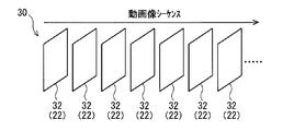
- a moving image 30 to be encoded is composed of a plurality of pictures (also referred to as picture images) 32 that are continuous in time series.
- the leftmost picture 32 is the first picture 32, that is, the first picture 32.
- the image data of each picture 32 corresponds to the image data 22 described above. Therefore, the image data 22 of each picture 32 is sequentially input to the encoding device 14.
- the picture 32 is a frame (also referred to as a frame image) in a non-interlace format (also referred to as a progressive format) is illustrated.
- the image data 22 is input to the encoding device 14 at, for example, a predetermined frame rate, in other words, at a predetermined time interval.
- a field also referred to as a field image
- a frame composed of two fields can be adopted as the picture 32.
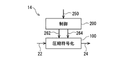
- FIG. 3 shows a block diagram outlining the encoding device 14.
- the encoding device 14 illustrated in FIG. 3 includes a compression encoding unit 100 and a control unit 200.
- compression encoding means and “control means” are abbreviated as “compression encoding” and “control”, respectively. This notation method is also used in the drawings described later.
- the compression encoding unit 100 acquires the original image data 22 as an input for each picture, and generates encoded data 24 by compressing and encoding the original image data 22 (generation processing). Then, the compression encoding unit 100 outputs the generated encoded data 24 to a wired or wireless transmission path (output process).
- the compression encoding is H.264.
- H.264 is exemplified.
- data generated by inter encoding hereinafter also referred to as inter encoded data
- intra encoded data data generated by intra encoding
- the intra-encoded data is data obtained by encoding the image data 22 of the picture 32 to be encoded regardless of the other pictures 32 (see FIG. 2). For this reason, intra-encoded data can be decoded by itself.
- Intra coded data is also referred to as an intra coded picture, an I picture, or the like.
- intra coding the picture 32 may be divided into a plurality of blocks (or macro blocks) and intra prediction using the correlation between the blocks may be performed.
- intra-encoded data refers to data encoded without depending on other pictures regardless of whether or not intra prediction is executed.
- Inter-encoded data is data obtained by encoding inter-prediction using inter-prediction using correlation with another picture 32 (or a predicted picture thereof). For this reason, inter-coded data cannot be decoded unless data of a picture (referred to as a reference picture or a reference screen) referred to at the time of inter prediction is used. Inter-coded data is also called an inter-coded picture. There are two types of inter-coded pictures: a P picture predicted based on a front picture and a B picture predicted based on a front picture and a rear picture. is there.
- the control unit 200 performs selection control as to which of the inter-encoded data and the intra-encoded data is output to the compression encoding unit 100. For example, the control unit 200 acquires a signal 250 related to an instruction or request for generating either inter-coded data or intra-coded data, and generates a control signal 262 corresponding to the content of the signal 250. Output to the compression encoding means 100. Thereby, the compression coding means 100 generates and outputs either inter-coded data or intra-coded data in accordance with the control signal 262.
- the signal 250 is a signal for requesting the generation of intra-encoded data
- the control signal 262 is a signal for causing the compression encoding unit 100 to generate intra-encoded data
- the control unit 200 obtains the intra encoded data generation request signal 250 and outputs the intra encoded data generation instruction signal 262 to the compression encoding unit 200.
- the signals 250 and 262 may be, for example, signals including information for distinguishing whether the generation request is intra-coded data or inter-coded data.
- control signal 250 is supplied from the outside of the control unit 200
- the control signal 250 may be a signal generated inside the control unit 200, as will be exemplified later. Absent.
- the control unit 200 also controls the compression encoding unit 100 on the amount of code generated by compression encoding (or the amount of code generated per unit time (so-called code generation rate)). For example, the control unit 200 generates the code amount control signal 264 by acquiring the intra encoded data request signal 250 and outputs the code amount control signal 264 to the compression encoding unit 100. Thereby, the compression encoding unit 100 sets the code amount according to the control signal 264.
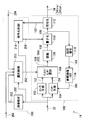
- FIG. 4 shows a block diagram outlining a more specific configuration example of the encoding device 14.
- H the present invention is not limited to the illustrated configuration example.
- the control unit 200 illustrated in FIG. 4 includes an image analysis unit 202, a selection control unit 212, and an encoding control unit 214.
- the intra prediction unit 102 receives the original image data 22 as input, generates intra prediction data (also referred to as an intra prediction picture) 152 by performing intra prediction on the image data 22, and outputs the prediction data 152. To do. Since intra prediction is a well-known method, detailed description thereof is omitted here.
- the inter prediction means 104 acquires the original image data 22 and data 164 (described later) stored in the reference image memory 116 as inputs. Then, the inter prediction unit 104 generates inter prediction data (also referred to as an inter prediction picture) 154 related to the input original image data 22 by performing inter prediction based on the data 22 and 164, and the prediction data 154 is output.
- inter prediction is a well-known method, the detailed description is abbreviate
- the intra / inter selection unit 106 receives the intra prediction data 152, the inter prediction data 154, and the control signal 262 output from the selection control unit 212 of the control unit 200 as inputs, and inputs both according to the selection instruction by the control signal 262. One of the prediction data 152 and 154 is selected, and the selected prediction data 156 is output.
- the conversion unit 108 acquires the prediction data 156 output from the intra / inter selection unit 106 as input, performs predetermined conversion on the prediction data 156, and outputs converted data 158.
- predetermined transformation so-called discrete cosine transformation (DCT) is exemplified.
- DCT discrete cosine transformation
- the prediction data 156 is orthogonally transformed into DCT coefficients 158 in the frequency domain.
- the quantization unit 110 acquires the DCT coefficient 158 and the control signal 264 output from the encoding control unit 214 of the control unit 200 as inputs.
- the quantization unit 110 converts the DCT coefficient 158 into the quantization coefficient 160 by performing quantization on the DCT coefficient 158 according to the content of the control signal 264, and outputs the obtained quantization coefficient 160.
- Such quantization is performed, for example, by dividing the DCT coefficient 158 by a quantization step and rounding the division result to an integer value. The quantization will be further described in the description of the encoding control unit 214.
- the encoding unit 112 obtains the quantized coefficient 160 as an input, generates encoded data 24 by performing predetermined encoding on the coefficient 160, and outputs the data 24.
- predetermined encoding for example, variable length encoding such as Huffman encoding or arithmetic encoding can be employed.
- the encoded data 24 may be output after the encoding of the entire picture is completed, or may be performed sequentially (for example, in units of slices) for one picture.
- the reference code “24tra” is used for the intra-coded data, and the reference code “24tra” is used for the inter-coded data, if necessary.
- the encoding unit 112 also outputs information 162 of the data amount of the generated encoded data 24 (in other words, the amount of generated code) to the encoding control unit 214 as appropriate.
- the local decoding unit 114 acquires the quantization coefficient 160 output from the quantization unit 110 as an input. Then, the local decoding unit 114 performs processing opposite to the quantization in the quantization unit 110 (referred to as inverse quantization) on the quantization coefficient 160 and the inverse of the discrete cosine transform in the conversion unit 108. Processing (called inverse discrete cosine transform, inverse DCT, etc.) is sequentially performed. Thereby, the reconstructed prediction data 164 is generated and output from the local decoding unit 114. Note that the local decoding unit 114 may perform, for example, intra compensation, motion compensation, or the like on the calculation result by inverse DCT.
- the reference image memory 116 is a means for storing the reconstructed prediction data 164 output from the local decoding means 114.
- the prediction data 164 stored in the memory 116 is used as a reference image when the inter prediction unit 104 performs inter prediction.
- the image analysis unit 202 acquires the original image data 22 as an input, detects a scene change (that is, a scene change) in the moving image 30 (see FIG. 2) based on the data 22, and outputs a signal 252 as a detection result. Output.
- the scene change can be detected, for example, by comparing the image data 22 of two consecutive pictures 32. More specifically, it is possible to determine that a scene change has occurred when a difference value, an average value, or the like between the image data 22 is larger than a predetermined threshold value. Conversely, when the difference value or the like is equal to or less than the threshold value, it can be determined that no scene change has occurred.
- the scene change detection signal 252 is an example of a signal 250 (see FIG. 3) that requests the compression encoding unit 100 to generate intra-encoded data 24tra.
- the request signal 250 may be generated inside the control unit 200, unlike the illustration of FIG.
- a moving image supply source controls the signal 254 for notifying the scene change together with the original image data 22.
- the moving image supply source can be configured to output, as the notification signal 254, information about whether or not the picture 32 hits the scene change position together with the drawing information of the picture 32.
- the scene change notification signal 254 can be transmitted.
- control unit 200 acquires both the signals 252 and 254, which are specific examples of the intra-encoded data request signal 250 (see FIG. 3).
- signals 252 and 254 which are specific examples of the intra-encoded data request signal 250 (see FIG. 3).
- a configuration in which only one of the signals 252 and 254 is acquired may be employed.
- the generation of the intra encoded data 24tra is required for error recovery even when a communication error occurs between the encoding device 14 and the decoding device 16 (see FIG. 1), for example.
- the request signal 256 transmitted from the decoding device 16 corresponds to an example of the intra encoded data request signal 250 given from the outside of the control means 200.
- the intra encoded data request signals 252, 254, and 256 are input to the selection control unit 212.
- the selection control means 212 can be configured using a register, for example. More specifically, for example, when the state “0” of the register is associated with a request for generation of intra-encoded data 24tra, and the state “1” of the register is requested to generate inter-encoded data 24ter To correspond to. In this case, the register is set to “0” by inputting at least one of the intra-encoded data request signals 252, 254, and 256. Thereafter, after the input of the image data 22 to be intra-encoded is confirmed, the register is set to “1”. The selection control unit 212 can output a control signal 262 for generating intra-coded data in accordance with the state of the register.
- the first picture 32 of the moving image 30 also needs to be converted into intra-coded data 24tra.
- the first picture 32 can be detected, for example, by detecting power-on of the encoding device 14.
- the register is configured to be reset to “0” when the encoding device 14 is turned on, thereby requesting intra coding for the image data 22 that is input first after the power is turned on. It is possible. After the input of the image data 22 of the first picture 32 is confirmed, the register is set to “1”.
- the power supplied when the power is turned on corresponds to an example of an intra-coded data request signal 250 generated inside the control unit 200.
- one register may be shared by the various aspects of the intra-encoded data request signal 250, or a register may be provided for each of the various aspects.
- the intra encoding instruction signal 262 output from the selection control unit 212 is input to the intra / inter selection unit 106 and the encoding control unit 214.
- the intra / inter selection means 106 outputs the intra prediction data 152 when the intra encoding instruction signal 262 is received, and outputs the inter prediction data 152 when the intra encoding instruction signal 262 is not received.
- the encoding control unit 214 outputs the control signal 264 related to the generation of the intra encoded data 24tra to the quantizing unit 110 in response to the reception of the intra encoding instruction signal 262. On the other hand, the encoding control unit 214 outputs a control signal 264 related to the generation of the inter encoded data 24ter to the quantizing unit 110 when the intra encoding instruction signal 262 is not received.
- control signal 264 includes information on quantization parameters having a predetermined relationship with the quantization step used in the quantization means 210. For this reason, the quantization means 110 derives a quantization step from the quantization parameter included in the control signal 264 according to the previously defined relationship, and performs quantization using the obtained quantization step.
- the encoding control unit 214 can control the quantization step via the quantization parameter included in the control signal 264.
- the encoding control unit 214 acquires the past code generation amount information 162 from the encoding unit 112. Can be set.
- a quantization parameter that is, a quantization step, irrespective of the past code generation amount.
- the quantization parameter has a proportional relationship with the quantization step.
- the quantization parameter is proportional to the logarithm of the quantization step.
- the quantization step increases as the quantization parameter increases.
- the quantization step is an index or index value indicating the roughness of the quantization (in other words, fineness). For this reason, the smaller the quantization step, in other words, the smaller the quantization parameter, the more the deterioration of the image quality is suppressed, but the code amount (in other words, the data amount) generated by the encoding means 112 increases. That is, the smaller the quantization step and the quantization parameter, the smaller the compression ratio.
- the encoding control unit 214 can control the amount of code generated by the compression encoding unit 100 by the control signal 264, more specifically by the quantization parameter included in the control signal 264. .
- code amount control will be described later.
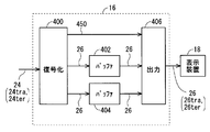
- FIG. 5 shows a block diagram outlining the decoding device 16.
- the display device 18 is also shown.
- the decoding device 16 illustrated in FIG. 5 includes a decoding unit 400, buffers 402 and 404, and a display device output unit 406.
- the decoding unit 400 acquires the encoded data 24 transmitted from the encoding device 14 (see FIG. 1) as an input. Then, the decoding unit 400 generates the decoded data 26 by decoding the acquired encoded data 24 according to a decoding method corresponding to the encoding method in the compression encoding unit 100 (see FIG. 4). The decrypted data 26 is output.
- the decoded data 26 obtained by decoding the intra-coded data 24tra is referred to as intra-decoded data 26tra
- the decoded data 26 obtained by decoding the inter-coded data 24ter is inter-decoded. This data will be referred to as converted data 26ter.
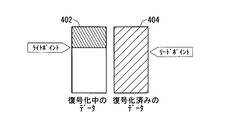
- the decoding unit 400 outputs the generated decoded data 26 (intra decoded data 26tra or inter decoded data 26ter) to one of the two buffers 402 and 404.
- the decoding unit 400 alternately uses the buffers 402 and 404 as storage destination buffers. For example, one buffer 402 is used for odd-numbered decoded data 26 and the other buffer 404 is used for even-numbered decoded data 26. According to such a double buffer configuration, it is possible to easily prevent the data 26 not read by the output means 406 from being overwritten and lost (see the schematic diagram of FIG. 6).
- the decoding unit 400 outputs a notification signal 450 indicating that to the output unit 406 along with the decoding of the intra encoded data 24tra. Note that the encoded data 24 is appended with information indicating whether the data 24 is intra-coded data 24tra or inter-coded data 24ter. Is possible.
- the notification signal 450 may adopt, for example, a signal form that is continued during the decoding of the intra-encoded data 24tra, or a signal form that is transmitted at the start and end of decoding. May be.
- the output means 406 is an interface that connects the decryption device 16 and the display device 18.
- the output means 406 basically selects the buffers 404 and 406 alternately, and reads the stored decoded data 26 (intra decoded data 26tra or inter decoded data 26ter) from the selected buffer.
- the output unit 406 repeatedly reads out the decoded data 26 from a buffer opposite to the buffer in which the intra decoded data 26tra is being stored until decoding of the intra encoded data 24tra is completed.
- the inter decoded data 26 corresponding to the inter encoded data 24ter received immediately before the intra encoded data 24tra being decoded is repeatedly read out.
- the output unit 406 can determine whether or not the intra-encoded data 24tra is being decoded based on the notification signal 450.
- the output unit 406 sequentially outputs the decoded data 26 sequentially read from the buffers 402 and 404 to the display device 18.
- FIG. 7 shows a schematic diagram outlining the operation of the system 12.
- the flow of the operation sequence is taken in the downward direction, and the passage of time is taken in the right direction.
- the original picture 32 to be processed and various data corresponding thereto are schematically illustrated by a figure in which a quadrangle is perspective.
- a quadrangle is perspective.
- the outline of the data amount of the picture 32 or the like is expressed by the area of the rectangle.
- the equal area among the three of the original image data 22, the encoded data 24, and the decoded data 26 does not necessarily mean that the data amount is the same.
- outlines of various time lengths related to the picture 32 and the like are expressed by the horizontal dimension of the rectangle.
- FIG. 7 shows an example of the processing status for the ⁇ m ⁇ 2 ⁇ th to ⁇ m + 3 ⁇ th input pictures 32, and the order is entered in the rectangle. That is, the characters in the rectangle are not images.
- intra coding or the like is performed on the mth picture 32 (shown in bold in the drawing for the sake of clarity), and inter coding or the like is performed on the remaining picture 32.
- m is an integer greater than or equal to 4, and it is assumed that the ⁇ m-2 ⁇ -th picture 32 is not the first (that is, the first) picture 32.
- the case where the mth picture 32 is the first picture can be easily understood from the following description.
- the image data 22 of the ⁇ m ⁇ 2 ⁇ th to ⁇ m + 3 ⁇ th pictures 32 is sent to the encoding device 14 in this order and every predetermined time T. Entered. That is, the image data 22 of the ⁇ m-2 ⁇ -th picture 32 is input within the first time T in the illustrated range of FIG. 7, and the image data of the ⁇ m-1 ⁇ -th picture 32 within the subsequent time T. 22) is input, and thereafter the image data 22 is sequentially input in the same manner.
- the predetermined time T is a time assigned in advance to one picture 32, and corresponds to one frame period here. For example, when the frame rate is 30 frames / second, the length of the time T is 1/30 seconds.
- the encoding device 14 performs compression encoding on each of the input image data 22 to generate encoded data 24.
- FIG. 7 illustrates a case where compression encoding is started without delay with respect to the input of the image data 22, it is not limited to such an example.
- each image data 22 is sequentially input at the intervals of the time T, the time per picture allowed for the processing (including generation and output of the encoded data 24) by the compression encoding means 100 is included. Is basically the time T.
- the encoding control means 214 (see FIG. 4) performs the following code amount control.
- the encoding control unit 214 depends on the transmission rate of the wired or wireless transmission path for transmitting the encoded data 24 to the decoding device 16.
- a code amount equal to or less than the maximum code amount (calculated by multiplying the upper limit transmission rate of the transmission path and the allowable time T) is set.
- the encoding control unit 214 is larger than the maximum code amount and N times the maximum code amount (N is an integer of 2 or more). The following code amount is set.
- the value of N is set in advance.
- the difference in the code amount (data amount) between the inter-coded data 24ter and the intra-coded data 24tra is expressed by the difference in the area of the quadrangle representing these data 24ter and 24tra. ing. Although all of the inter-coded data 24ter is illustrated with the same area, this is merely a simplified illustration to avoid complication of the drawing.
- the horizontal dimension of the rectangle representing the encoded data 24 represents an outline of the generation time of the encoded data 24.
- the output of the inter-coded data 24ter can be completed within the allowable time T per picture.
- the intra-coded data 24tra that has been increased from the maximum code amount cannot be output within the allowable time T due to the limitation of the transmission rate. For this reason, a processing time Ttra that is N times the allowable time T is assigned to the generation / output of the intra-coded data 24tra.
- the generation of the intra encoded data 24tra itself can be completed within the allowable time T, but the output of the generated encoded data 24tra is subjected to the transmission rate limitation.
- ⁇ T ⁇ 2 ⁇ processing time is required for the entire processing related to the intra-coded data 24tra.
- the image data 22 of the next ⁇ m + 1 ⁇ th picture 32 is supplied to the compression coding means 100 while the intra encoded data 24tra corresponding to the mth picture 32 is being output to the transmission path.
- the compression encoding means 100 does not generate and output the encoded data 24 for the ⁇ m + 1 ⁇ th input image data 22, but encodes the next ⁇ m + 2 ⁇ th input image data 22.
- the generation and output of data 24 is resumed. That is, the ⁇ m + 1 ⁇ th input image data 22 is thinned out for generation and output of the encoded data 24.
- the generation and output of the encoded data 24 are not performed for ⁇ N ⁇ 1 ⁇ pictures 32 following the picture 32 corresponding to the intra encoded data 24tra, and the next of the ⁇ N ⁇ 1 ⁇ pictures 32.
- the picture 32 is resumed.
- the intra / inter selection means 106 obtains the value of N in advance and counts the number ⁇ N-1 ⁇ to be thinned out. This can be realized by not outputting any inter prediction data 154.
- the encoding unit 112 may perform the output limitation and the cancellation of the intra / inter selection unit 106.
- the encoding unit 112, the control unit 200, or the like may perform data input restriction on the encoding unit 112 or the compression encoding unit 100 and release it.
- the encoded data 24 sequentially transmitted from the encoding device 14 is sequentially received by the decoding device 16. 7, the encoded data 24 received by the decoding device 16 corresponds to the ⁇ m + 1 ⁇ -th picture 32 thinned out by the encoding device 14. Inter-coded data 24ter is not included.
- the square area representing the encoded data 24 represents the outline of the code amount (data amount) as in the second level.
- the horizontal dimension of the square representing the encoded data 24 represents the outline of the reception time of the encoded data 24.
- the encoded data 24ter and 24tra are respectively stored at predetermined times T and Ttra as shown in the third row of FIG.
- the reception can be completed within.
- reception of the increased amount of intra-encoded data 24tra takes a time Ttra longer than the allowable time T as a result of the limitation of the transmission rate of the transmission path.
- FIG. 7 illustrates a delay time D from the start of compression encoding (here, when the image data 22 is input to the encoding device 14) until the encoded data 24 reaches the decoding device 16. is doing.
- the delay time D includes a processing time spent for generating and outputting the encoded data 24 and a transmission time spent for transmission between the devices 14 and 16.
- the decoding device 16 decodes the input encoded data 24 to generate decoded data 26.
- FIG. 7 illustrates a case where decoding is started without delay with respect to the input of the encoded data 24, it is not limited to such an example.
- the area of the square representing the encoded data 24 represents the outline of the code amount (data amount) as in the second level and the third level.
- the horizontal dimension of the rectangle representing the encoded data 24 represents an outline of the processing time required for decoding the encoded data 24.
- the decoding of the encoded data 24ter and 24tra can be completed within a predetermined time T and Ttra, respectively.
- the reception itself takes longer than the allowable time T, so that decoding also takes longer than the allowable time T.
- the decoding device 16 sequentially outputs the decoded data 26 to the display device 18 as described above. Thereby, the image based on each decoding data 26 is continuously displayed on the display device 18, and the decoded moving image is obtained.
- FIG. 7 illustrates a case where there is a delay of the same length as the processing time T from the start of decoding until the decoded data 26 is output, but is not limited to this example. .
- the decoding processing time Ttra of the intra encoded data 24tra is longer than the decoding processing time T of the inter encoded data 24ter. For this reason, after the output of the inter decoded data 26ter corresponding to the ⁇ m ⁇ 1 ⁇ th picture 32, the decoding of the intra decoded data 26ter corresponding to the mth picture 32 has not been completed. sell.
- the output unit 406 of the decoding device 16 has the inter decoded data 26ter immediately before the intra decoded data 26tra, that is, the ⁇ m ⁇ 1 ⁇ th, as shown in the bottom of FIG.
- the decoded data 26ter corresponding to the picture 32 is output again.
- the decoded data 26ter corresponding to the ⁇ m ⁇ 1 ⁇ th picture 32 is displayed again.
- the inter decoded data 26ter corresponding to the inter encoded data 24ter received immediately before the intra encoded data 24tra is repeatedly output to the display device 18 until the decoding of the intra encoded data 24tra is completed.
- the repeated display of the same decoded data 26ter is preferably limited to the time when it is not recognized as a still image by human eyes. This is because if the same image (pattern) continues beyond a predetermined time, it is likely to be recognized as a still image by human eyes, and as a result, the image quality as a moving image may be deteriorated.
- the predetermined time is approximately 0.1 seconds, although there are individual differences. In other words, for example, when the frame rate of the input moving image is 30 frames / second, it is preferable to select 2 or 3 as the value of N (N is an integer of 2 or more).
- the decoding device 16 According to the encoding device 14, the decoding device 16, the system 12, and the various techniques employed in these, the following effects can be obtained.
- the code amount of the intra-coded data 24tra is set to be larger than the maximum code amount specified based on the transmission rate of the transmission path. For this reason, the picture quality of the picture obtained by decoding the intra-coded data is improved as compared with the case where the code quantity of the intra-coded data 24tra is set to be equal to or less than the maximum code quantity as with the inter-coded data 24ter. Can be made. Furthermore, as a result, the image quality of the entire decoded moving image can be improved.
- the maximum code amount that is generated for both inter-coded data and intra-coded data is determined according to the transmission rate.
- the quantization parameter was controlled to be as follows.
- the encoding device 14 allows a code amount exceeding the maximum code amount for intra-encoded data.
- the output is limited by the transmission rate, it takes more time to complete the output to the transmission path than the inter-coded data.
- FIGS. 8 and 9 illustrate a case where the amount of inter-coding is fluctuating.
- the amount of generated code depends on the design (content of the image), so it is very difficult to make the amount of code constant. Therefore, the example illustrated here is an example of the result of encoding with the aim of high image quality as much as possible below the upper limit of the code amount by the communication band, that is, a high code amount.
- the second stage of FIG. 7 illustrates an aspect in which the generation of the intra encoded data 24tra itself can be completed within the allowable time T as described above.
- the second row of FIG. 10 it is also possible to perform inter coding on the ⁇ m + 1 ⁇ th picture 32 that has been thinned out in the above.
- output delay and delay accumulation occur as described above.
- the encoded data 24 that is not scheduled to be output to the transmission path is not even generated as shown in the example of FIG. 7 in order to reduce the processing amount. Note that, as a result of the reduction in processing amount, it is possible to save power.
- the compression encoding means 100 has the performance that the intra encoded data 24tra itself can be completed within the allowable time T as described above, it takes a long time Ttra to complete the output due to the transmission rate. If there is, the generation time of the intra encoded data 24tra may be longer than the allowable time T (see FIG. 11).
- the processing related to the intra-coded data 24tra may be performed over the entire processing time Ttra that is longer than the allowable time T and not longer than N times the allowable time T.
- the intra encoded data 24tra can be generated with a code amount exceeding the maximum code amount, and the increased intra encoded data 24tra can be transmitted while limiting the transmission rate. Output can be completed.
- the processing load of the compression encoding means 100 can be reduced as compared with the example of FIG. Further, since the necessity of adopting a high-performance configuration for the compression encoding unit 100 is reduced as the processing load is reduced, cost reduction, power saving, and the like can be achieved.
- the intra-encoded data 24tra requires a longer decoding time than the inter-encoded data 24ter. However, until the decoding of the intra-encoded data 24tra is completed, the immediately preceding inter-encoded data 24ter is changed. The decoded image is repeatedly displayed. For this reason, it is possible to prevent an image loss (for example, an image of a full black display is interrupted) in the decoded moving image.
- the quality of a moving image can be improved by preventing image loss and further preventing display defects caused by the image loss (for example, the image flickers due to the presence of the image loss).
- the compression encoding unit 100 performs predetermined processing (including generation and output to the transmission path) on the intra-encoded data 24tra longer than the allowable time T and N times the allowable time T. It is sufficient to take a processing time less than this time.
- the code amount of the intra-coded data 24tra can be made larger than the maximum code amount that can be generated / output within the allowable time T per picture. For this reason, it is possible to improve the picture quality of a picture obtained by decoding the intra-encoded data 24tra as compared with the case where only the allowable time T is allocated to the intra-encoded data 24tra. Furthermore, as a result, the image quality of the entire decoded moving image can be improved.
- the processing load on the compression encoding means 100 can be reduced as compared with the case where the increased amount of intra encoded data 24tra is generated within the allowable time T. For this reason, the necessity for adopting a high-performance configuration for the compression encoding means 100 is reduced, and a configuration with a low processing speed can be employed. As a result, cost reduction and power saving can be achieved.
- the image immediately after the scene change is encoded as an I picture and set at the beginning of a new GOP (Group Of Picture).
- the picture type (type of I, P, B picture) is determined based on the detection result of the scene change and the accumulated data of the result of encoding in the past, and the determined picture type
- the encoding bit rate is controlled according to the above.
- a method of changing the GOP length and a method of fixing the GOP length and allocating the information amount of each picture at the fixed length are introduced.
- Patent Document 1 does not disclose the above-described various methods employed in the encoding device 14 or the like. For example, a method for increasing the code amount of the intra-coded data 24tra while satisfying the restriction caused by the transmission rate of the transmission path and the restriction caused by the performance of the compression coding means 100 to improve the image quality is as follows. This is not disclosed in Patent Document 1. Further, for example, Patent Document 1 does not disclose a method of thinning out image data 22 input during execution of intra coding. Also, Patent Document 1 does not disclose a method for repeatedly outputting inter decoded data 26ter immediately before the intra decoded data 26tra to the display device.
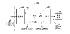
- FIG. 12 shows a block diagram outlining the decoding device 16B adopting a single buffer configuration.
- the decoding device 16B has a configuration in which the two buffers 404 and 406 are changed to one buffer 410 in the decoding device 16 (see FIG. 5).
- both intra decoded data 26tra and inter decoded data 26ter are stored in the buffer 410.
- the output means 406 instructs the write permission / prohibition with respect to the decryption means 400 with the signal 452 to prevent the necessary data 26 from being overwritten and lost.
- the storage area of the decoded data 26 that has been output to the display device 18 can be overwritten.
- the generation of such an overwrite-permitted area or the designation of the position of the area is notified to the decoding means 400 by a write permission signal 452.
- the decoding unit 400 Upon receiving the signal 452, the decoding unit 400 performs decoding and writes the decoded data 26 in the permissible area (see the schematic diagram in FIG. 13).
- the write permission signal 452 may be transmitted when a storage area having a size capable of storing the entire decoded data 26 is generated, or the decoded data 26 may be partially (for example, in block units). It may be transmitted when a storage area of a size that can be stored is generated.
- ⁇ Modification 2> a case where both the intra prediction data 152 and the inter prediction data 154 are generated for the same input image data 22 is illustrated (see FIG. 4).
- the control unit 200 controls only one of the intra prediction unit 102 and the inter prediction unit 104 in accordance with reception / non-reception of the intra encoding request signal 250 (see FIG. 3), so that intra prediction is performed. It is also possible to modify to generate only one of the data 152 and the inter prediction data 154. In such a case, the various effects described above can be obtained.
- intra coding is a process of coding a target picture 32 without depending on other pictures 32.
- intra coding includes a case where the input image data 22 is coded as it is without performing intra prediction.
- FIG. 14 illustrates a block diagram of the encoding device 14B in view of this point.
- the intra prediction unit 102 is removed from the configuration illustrated in FIG. 4, the input image data 22 is input to the intra / inter selection unit 106, and the input image data 22 and the inter prediction from the intra / inter selection unit 106 are input. Either data 154 or one of them is output.
- Other configurations of the encoding device 14B are the same as those of the encoding device 14 (see FIG. 4). The various effects described above can also be obtained by the encoding device 14B.
Abstract
動画像の符号化に伴う画質低下を抑制可能な装置等を提供する。圧縮符号化手段(100)は、入力動画像を構成する各ピクチャの画像データ(22)に圧縮符号化を行ってインター符号化データ(24ter)またはイントラ符号化データ(24tra)を生成し、符号化データ(24ter,24tra)を有線または無線の伝送路へ出力する。制御手段(200)は、圧縮符号化手段(100)にインター符号化データ(24ter)を生成させる場合、伝送路の上限伝送レートと、入力動画像のピクチャレートに基づいて1ピクチャ当たりに割り当てられる許容時間との乗算値で与えられる最大符号量以下の符号量を設定する。他方、制御手段(200)は、圧縮符号化手段(100)にイントラ符号化データ(24tra)を生成させる場合、上記最大符号量よりも多く上記最大符号量のN倍(Nは2以上の整数)以下の符号量を設定する。
Description
本発明は、画像符号化装置、画像符号化復号化システム、画像符号化方法、画像表示方法に係る。
動画像の符号化方式としては、例えば、H.264、MPEG(Moving Picture Experts Group)-2、およびMPEG-4等が知られている。なお、一般に、符号化の際にはデータ圧縮が行われることが多く、このため「符号化」と「圧縮符号化」とが同義で用いられる場合がある。かかる実情に鑑み、本明細書でも基本的には両者を同義で用いることにする。
上記方式ではイントラ符号化とインター符号化が併用されている。イントラ符号化は、動画像を構成するピクチャを、他のピクチャとは無関係に、そのピクチャだけで符号化する手法である。このため、イントラ符号化されたピクチャ(以下、イントラ符号化ピクチャとも称する)は、それ単独で復号化可能である。なお、イントラ符号化ピクチャはIピクチャ(Intra-Picture)とも称される。
他方、インター符号化は、他のピクチャとの相関性を利用してインター予測(画面間予測、ピクチャ間予測等とも称される)を行い、その予測結果、すなわち予測ピクチャを符号化する手法である。インター予測は、他のピクチャについての予測ピクチャとの間で行われる場合もある。インター符号化されたピクチャ(以下、インター符号化ピクチャとも称する)は、インター予測時に参照したピクチャ(参照ピクチャ、参照画面等と称される)を利用しなければ復号化することができない。なお、インター符号化ピクチャには、動画像シーケンスにおける前方のピクチャに依拠して符号化されたPピクチャ(Predictive-Picture)と、前方および後方のピクチャに依拠して符号化されたBピクチャ(Bidirectional predictive-Picture)との2種類がある。
なお、イントラ符号化において、符号化の対象とするピクチャを複数のブロック(またはマクロブロック)に分割し、ブロック間の相関性を利用してイントラ予測(画面内予測、ピクチャ内予測等とも称される)が行われる場合もある。
なお、本発明に関連すると思われる技術が下記特許文献1に開示されている(後述する)。
符号化ピクチャを有線または無線の通信によって伝送する場合、伝送路の通信帯域(換言すれば伝送レート)の制限内に収まるように、生成する符号化データの量(換言すれば符号量)を制御する必要がある。
また、動画像はピクチャの連続により構成されているので、順次入力される各ピクチャに対して費やすことができる処理時間(換言すれば処理遅延)には制限がある。このため、処理時間の長さに応じて、符号量が制御される。
しかし、符号量が少ないと、復号化されたピクチャの画質は低くなってしまう。一般にイントラ符号化ピクチャはインター符号化ピクチャに比べて符号量が多くなる。このため、上記各種制限に適合させるために符号量を削減した場合、イントラ符号化ピクチャの方がインター符号化ピクチャに比べて削減量が大きくなる。
したがって、イントラ符号化ピクチャの方が画質低下を起こしやすい。また、イントラ符号化ピクチャに対応する復号化ピクチャが低画質の場合、動画像全体の画質低下を招く場合もある。
そこで、本発明は、動画像の符号化に関して各種制限に適合させつつ画質低下を抑制可能な技術を提供することを目的とする。また、そのような符号化の処理負荷を低減可能な技術を提供することを目的とする。また、そのような符号化技術に好適な動画像表示技術を提供することを目的とする。
本発明の第1の態様に係る画像符号化装置は、入力動画像を構成する各ピクチャの画像データに圧縮符号化を行ってピクチャごとにインター符号化データとイントラ符号化データとのうちのいずれか一方を生成する生成処理と、生成された符号化データを有線または無線の伝送路へ出力する出力処理とを含んだ所定処理を行う、圧縮符号化手段と、前記圧縮符号化手段に対し、前記インター符号化データと前記イントラ符号化データとのうちのいずれを生成させるかについての制御と、前記圧縮符号化によって生成される符号量の制御とを行う、制御手段とを備え、前記制御手段は、前記圧縮符号化手段に前記インター符号化データを生成させる場合、前記伝送路の上限伝送レートと、前記入力動画像のピクチャレートに基づいて1ピクチャ当たりに割り当てられる許容時間との乗算値で与えられる最大符号量以下の符号量を設定し、前記圧縮符号化手段に前記イントラ符号化データを生成させる場合、前記最大符号量よりも多く前記最大符号量のN倍(Nは2以上の整数)以下の符号量を設定する。
また、第2の態様に係る画像符号化装置は、上記の第1の態様に係る画像符号化装置であって、前記圧縮符号化手段は、前記イントラ符号化データについての前記所定処理を、前記許容時間よりも長く前記許容時間の前記N倍の時間以下の処理時間をかけて行う。
また、第3の態様に係る画像符号化装置は、上記の第1または第2の態様に係る画像符号化装置であって、前記圧縮符号化手段は、前記イントラ符号化データに対応する前記ピクチャに続く{N-1}枚のピクチャについては、前記所定処理のうちの少なくとも前記出力処理を行わない。
また、第4の態様に係る画像符号化装置は、上記の第3の態様に係る画像符号化装置であって、前記圧縮符号化手段は、前記{N-1}枚のピクチャについては、前記所定処理のうちで前記生成処理も行わない。
また、第5の態様に係る画像符号化装置は、入力動画像を構成する各ピクチャの画像データに圧縮符号化を行ってピクチャごとにインター符号化データとイントラ符号化データとのうちのいずれか一方を生成する生成処理と、生成された符号化データを有線または無線の伝送路へ出力する出力処理とを含んだ所定処理を行う、圧縮符号化手段と、前記圧縮符号化手段に対し、前記インター符号化データと前記イントラ符号化データとのうちのいずれを生成させるかについての制御と、前記圧縮符号化によって生成される符号量の制御とを行う、制御手段とを備え、前記圧縮符号化手段は、前記イントラ符号化データについての前記所定処理を、前記入力動画像のピクチャレートに基づいて1ピクチャ当たりに割り当てられる許容時間よりも長く前記許容時間のN倍(Nは2以上の整数)の時間以下の処理時間をかけて行う。
また、第6の態様に係る画像符号化装置は、上記の第5の態様に係る画像符号化装置であって、前記圧縮符号化手段は、前記イントラ符号化データに対応する前記ピクチャに続く{N-1}枚のピクチャについては、前記所定処理を行わない。
また、第7の態様に係る画像符号化復号化システムは、上記の第1ないし第6のうちのいずれか1つの態様に係る画像符号化装置と、前記画像符号化装置と前記有線または無線の伝送路を介して通信可能に設けられた画像復号化装置とを備え、前記画像復号化装置は、前記画像符号化装置から前記符号化データを受信し、前記符号化データに基づいて、前記圧縮符号化に対応する復号化を行うことによって復号化データを生成する、復号化手段と、前記復号化によって順次生成される前記復号化データを表示装置向けに順次出力する出力手段とを含んでおり、前記出力手段は、前記イントラ符号化データについての前記復号化が終了するまで、当該イントラ符号化データの直前に受信した前記インター符号化データに対応するインター復号化データを繰り返し表示装置向けに出力する。
また、第8の態様に係る画像符号化方法は、(a)入力動画像を構成する各ピクチャの画像データに圧縮符号化を行ってピクチャごとにインター符号化データとイントラ符号化データとのうちのいずれか一方を生成する生成処理と、生成された符号化データを有線または無線の伝送路へ出力する出力処理とを含んだ所定処理を行うステップと、(b)前記ステップ(a)に関して、前記インター符号化データと前記イントラ符号化データとのうちのいずれを生成させるかについての制御と、前記圧縮符号化によって生成される符号量の制御とを行うステップとを備え、前記ステップ(b)では、前記ステップ(a)で前記インター符号化データを生成させる場合、前記伝送路の上限伝送レートと、前記入力動画像のピクチャレートに基づいて1ピクチャ当たりに割り当てられる許容時間との乗算値で与えられる最大符号量以下の符号量を設定し、前記ステップ(a)で前記イントラ符号化データを生成させる場合、前記最大符号量よりも多く前記最大符号量のN倍(Nは2以上の整数)以下の符号量を設定する。
また、第9の態様に係る画像符号化方法は、上記の第8の態様に係る画像符号化方法であって、前記ステップ(a)では、前記イントラ符号化データについての前記所定処理を、前記許容時間よりも長く前記許容時間の前記N倍の時間以下の処理時間をかけて行う。
また、第10の態様に係る画像符号化方法は、上記の第8または第9の態様に係る画像符号化方法であって、前記ステップ(a)では、前記イントラ符号化データに対応する前記ピクチャに続く{N-1}枚のピクチャについては、前記所定処理のうちの少なくとも前記出力処理を行わない。
また、第11の態様に係る画像符号化方法は、上記の第10の態様に係る画像符号化方法であって、前記ステップ(a)では、前記{N-1}枚のピクチャについては、前記所定処理のうちで前記生成処理も行わない。
また、第12の態様に係る画像符号化方法は、(a)入力動画像を構成する各ピクチャの画像データに圧縮符号化を行ってピクチャごとにインター符号化データとイントラ符号化データとのうちのいずれか一方を生成する生成処理と、生成された符号化データを有線または無線の伝送路へ出力する出力処理とを含んだ所定処理を行うステップと、(b)前記ステップ(a)に関して、前記インター符号化データと前記イントラ符号化データとのうちのいずれを生成させるかについての制御と、前記圧縮符号化によって生成される符号量の制御とを行うステップとを備え、前記ステップ(a)では、前記イントラ符号化データについての前記所定処理を、前記入力動画像のピクチャレートに基づいて1ピクチャ当たりに割り当てられる許容時間よりも長く前記許容時間のN倍(Nは2以上の整数)の時間以下の処理時間をかけて行う。
また、第13の態様に係る画像符号化方法は、上記の第12の態様に係る画像符号化方法であって、前記ステップ(a)では、前記イントラ符号化データに対応する前記ピクチャに続く{N-1}枚のピクチャについては、前記所定処理を行わない。
また、第14の態様に係る画像表示方法は、上記の第8ないし第13のうちのいずれか1つの態様に係る画像符号化方法によって生成された前記符号化データを、前記有線または無線の伝送路を介して受信するステップと、(d)前記ステップ(c)で受信した前記符号化データに基づいて、前記圧縮符号化に対応する復号化を行うことによって復号化データを生成するステップと、(e)前記ステップ(d)によって順次生成される前記復号化データに基づいて表示装置に画像表示を行わせるステップとを備え、前記ステップ(e)では、前記ステップ(d)において前記イントラ符号化データについての前記復号化が終了するまで、当該イントラ符号化データの直前に受信した前記インター符号化データに対応するインター復号化データを繰り返し用いて前記画像表示を行う。
上記の第1および第8の態様によれば、イントラ符号化データの符号量が、伝送路の伝送レートに基づいて規定される上記最大符号量よりも多く設定される。このため、イントラ符号化データの符号量が上記最大符号量以下に設定される場合に比べて、イントラ符号化データを復号化して得られるピクチャの画質を向上させることができる。さらには、その結果として、復号化された動画像全体の画質を向上させることができる。
上記の第2および第9の態様によれば、イントラ符号化データを上記最大符号量を超える符号量で以て生成可能であり、かつ、そのように増量されたイントラ符号化データを伝送レートの制限に従いつつも伝送路へ出力完了可能な一形態を提供することができる。かかる一態様によれば、イントラ符号化データについての上記所定処理を1ピクチャ当たりの許容時間内で終了させる場合に比べて、圧縮符号化手段の処理負荷を低減することができる。また、処理負荷低減に伴って圧縮符号化手段に高性能な構成を採用する必要性が低くなるため、低コスト化、省電力化等を図ることができる。
上記の第3および第10の態様によれば、上記{N-1}枚のピクチャは伝送路への出力について間引かれるため、伝送路へ出力されるデータ量(符号量)を抑制することができる。伝送レートの制限に鑑みれば、上記増量されたイントラ符号化データの出力完了のために、上記{N-1}枚のピクチャ分の許容時間も費やされる。したがって、上記{N-1}枚のピクチャの出力を間引かない場合には、伝送路へのデータ出力が順次遅延していき、さらにはイントラ符号化データの出力の度に遅延が累積していくことになる。これに対し、上記の第3および第10の態様によれば、そのような出力遅延および遅延累積を防止することができる。
上記の第4および第11の態様によれば、上記{N-1}枚のピクチャ分の処理量が削減される。これにより、省電力化等を図ることができる。
上記の第5および第12の態様によれば、イントラ符号化データの符号量を、1ピクチャ当たりの許容時間内で生成・出力可能な最大符号量よりも、多くすることができる。このため、イントラ符号化データに上記許容時間しか割り当てない場合に比べて、イントラ符号化データを復号化して得られるピクチャの画質を向上させることができる。さらには、その結果として、復号化された動画像全体の画質を向上させることができる。
また、上記の第5および第12の態様によれば、上記増量されたイントラ符号化データを上記許容時間内で生成させる場合に比べて、圧縮符号化手段の処理負荷を低減することができる。また、処理負荷低減に伴って圧縮符号化手段に高性能な構成を採用する必要性が低くなるため、低コスト化、省電力化等を図ることができる。
上記の第6および第13の態様によれば、上記{N-1}枚のピクチャは伝送路への出力について間引かれるため、伝送路へ出力されるデータ量(符号量)を抑制することができる。上記{N-1}枚のピクチャの出力を間引かない場合には、伝送路へのデータ出力が順次遅延していき、さらにはイントラ符号化データの出力の度に遅延が累積していくことになる。これに対し、上記の第6および第13の態様によれば、そのような出力遅延および遅延累積を防止することができる。
また、上記の第6および第13の態様によれば、上記{N-1}枚のピクチャ分の処理量が削減される。これにより、省電力化等を図ることができる。
上記の第7および第14の態様によれば、イントラ符号化データにはインター符号化データよりも長い復号化処理時間が必要になるところ、イントラ符号化データの復号化が終了するまでの間は直前のインター符号化データを復号化した画像が繰り返し表示される。このため、復号化した動画像において画像の欠損(例えば全面黒表示の画像が割り込む等)が生じないようにすることができる。画像欠損の防止、さらには画像欠損に起因した表示不具合(例えば画像欠損の存在により画像がちらつく等)の防止により、動画像の画質を向上させることができる。
この発明の目的、特徴、局面、および利点は、以下の詳細な説明と添付図面とによって、より明白となる。
<画像符号化復号化システム12>
図1に、本発明の実施の形態に係る画像符号化復号化システム12を概説するブロック図を示す。図1の例によれば、画像符号化復号化システム12は、画像符号化装置14と、画像復号化装置16とを含んでいる。なお、説明を分かりやすくするため、図1には表示装置18を併記している。
図1に、本発明の実施の形態に係る画像符号化復号化システム12を概説するブロック図を示す。図1の例によれば、画像符号化復号化システム12は、画像符号化装置14と、画像復号化装置16とを含んでいる。なお、説明を分かりやすくするため、図1には表示装置18を併記している。
なお、以下では「画像符号化復号化システム」、「画像符号化装置」および「画像復号化装置」を、「システム」、「符号化装置」および「復号化装置」とそれぞれ略称する場合もある。
符号化装置14は、動画像の画像データ22を入力として取得し、当該画像データ22を所定の符号化方式に従って符号化することにより符号化データ24を生成し、当該符号化データ24を出力する。入力画像データ22(換言すれば原画像データ22)は、例えば、不図示の動画像供給源から供給される。
復号化装置16は、符号化装置14と有線または無線による通信が可能に構成されており、符号化装置14から符号化データ24を取得する。復号化装置16は、取得した符号化データ24を所定の復号化方式に従って復号化することにより復号化データ26を生成し、当該復号化データ26を出力する。
復号化装置16における上記所定の復号化方式は、符号化装置14における上記所定の符号化方式に対応するものである。換言すれば、両方式は同じまたは互換性のある符号化復号化方式に準拠している。符号化復号化方式として、例えば、H.264、MPEG-2、MPEG-4等が挙げられる。
表示装置18は、復号化装置16と有線または無線による通信が可能に構成されており、復号化装置16から復号化データ26を取得する。表示装置18は、取得した復号化データに従って動画像の表示を行う。
なお、表示装置18は、復号化装置16と同じ筐体に収容された形態を採ってもよいし、あるいは、復号化装置16とは別の筐体に収容された形態を採ってもよい。
ここで、符号化装置14で符号化される動画像について、図2を参照して概説する。図2に模式的に示すように、符号化の対象となる動画像30は、時系列に連続する複数のピクチャ(ピクチャ画像とも称される)32で構成されている。なお、図2の例では、左端のピクチャ32が先頭のピクチャ32、すなわち第1番目のピクチャ32である。かかる動画像構成の下、各ピクチャ32の画像データが上記の画像データ22にあたる。このため、符号化装置14には、各ピクチャ32の画像データ22が順次入力される。
ここでは、ピクチャ32が、ノン・インターレース方式(プログレッシブ方式とも称される)におけるフレーム(フレーム画像とも称される)である場合を例示する。この場合、画像データ22は、例えば所定のフレームレートで以て、換言すれば所定長さの時間間隔で以て、符号化装置14へ入力される。
但し、ピクチャ32として、インターレース方式におけるフィールド(フィールド画像とも称される)を採用することも可能である。あるいは、インターレース方式であっても、2枚のフィールドから構成されたフレームをピクチャ32として採用することも可能である。
<画像符号化装置14>
図3に、符号化装置14を概説するブロック図を示す。図3に例示の符号化装置14は、圧縮符号化手段100と、制御手段200とを含んでいる。なお、図3では「圧縮符号化手段」および「制御手段」を「圧縮符号化」および「制御」とそれぞれと略称している。かかる表記方法は後述の図面においても用いることにする。
図3に、符号化装置14を概説するブロック図を示す。図3に例示の符号化装置14は、圧縮符号化手段100と、制御手段200とを含んでいる。なお、図3では「圧縮符号化手段」および「制御手段」を「圧縮符号化」および「制御」とそれぞれと略称している。かかる表記方法は後述の図面においても用いることにする。
圧縮符号化手段100は、ピクチャごとに、原画像データ22を入力として取得し、当該原画像データ22を圧縮符号化することにより符号化データ24を生成する(生成処理)。そして、圧縮符号化手段100は、生成した符号化データ24を、有線または無線の伝送路へ出力する(出力処理)。ここでは、圧縮符号化がH.264に準拠する場合を例示する。かかる例の場合、ピクチャ32ごとに、符号化データ24として、インター符号化によって生成されたデータ(以下、インター符号化データとも称する)とイントラ符号化によって生成されたデータ(以下、イントラ符号化データとも称する)とのうちのいずれか一方が出力される。
ここで、イントラ符号化データは、他のピクチャ32(図2参照)とは無関係に、符号化の対象となるピクチャ32の画像データ22を符号化したデータである。このため、イントラ符号化データは、それ単独で復号化可能である。イントラ符号化データは、イントラ符号化ピクチャ、Iピクチャ等とも称される。
イントラ符号化では、ピクチャ32を複数のブロック(またはマクロブロック)に分割し、ブロック間の相関性を利用したイントラ予測が行われる場合がある。但し、イントラ符号化データとは、イントラ予測の実行/不実行とは無関係に、他のピクチャに依拠することなく符号化されたデータを言うものとする。
インター符号化データは、他のピクチャ32(またはそれの予測ピクチャ)との相関性を利用したインター予測が行われ、その予測結果を符号化したデータである。このため、インター符号化データは、インター予測時に参照したピクチャ(参照ピクチャ、参照画面等と称される)のデータを利用しなければ復号化することができない。インター符号化データはインター符号化ピクチャとも称され、インター符号化ピクチャには前方のピクチャに基づいて予測されたPピクチャと、前方および後方のピクチャに基づいて予測されたBピクチャとの2種類がある。
制御手段200は、圧縮符号化手段100に対し、インター符号化データとイントラ符号化データとのうちのいずれを出力させるかについての選択制御を行う。例えば、制御手段200は、インター符号化データとイントラ符号化データとのうちのいずれを生成させるかについての指示または要求に関する信号250を取得し、当該信号250の内容に対応する制御信号262を生成し圧縮符号化手段100へ出力する。これにより、圧縮符号化手段100は、制御信号262に従って、インター符号化データとイントラ符号化データとのうちのいずれかを生成し出力する。
ここでは、信号250はイントラ符号化データの生成を要求する信号であり、制御信号262が圧縮符号化手段100にイントラ符号化データを生成させる旨の信号である場合を例示する。かかる例の場合、制御手段200は、イントラ符号化データの生成要求信号250を取得することによって、イントラ符号化データの生成指示信号262を圧縮符号化手段200へ出力する。但し、信号250,262は、例えば、イントラ符号化データとインター符号化データとのいずれに対する生成要求であるかを区別する情報を含んだ信号であってもよい。
なお、図3では制御信号250が制御手段200の外部から供給される場合を例示しているが、後に例示するように制御信号250は制御手段200の内部で生成される信号であっても構わない。
制御手段200は、また、圧縮符号化手段100に対し、圧縮符号化によって生成される符号量(あるいは単位時間当たりに生成する符号量(いわゆる符号生成レート))の制御を行う。例えば、制御手段200は、上記のイントラ符号化データ要求信号250を取得することによって、符号量制御信号264を生成し、圧縮符号化手段100へ出力する。これにより、圧縮符号化手段100は、制御信号264に従って符号量を設定する。
ここでは、符号量は、イントラ符号化データの生成とインター符号化データの生成のいずれにおいても、制御信号264によって制御される場合を例示する。
図4に、符号化装置14のより具体的な構成例を概説するブロック図を示す。ここではH.264に準拠した構成を例示しているが、図示の構成例に限定されるものではない。
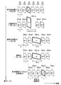
図4に例示の圧縮符号化手段100は、イントラ予測手段102と、インター予測手段104と、イントラ/インター選択手段106と、変換手段108と、量子化手段110と、符号化手段112と、局所復号手段114と、参照画像メモリ116とを含んでいる。また、図4に例示の制御手段200は、画像解析手段202と、選択制御手段212と、符号化制御手段214とを含んでいる。
イントラ予測手段102は、原画像データ22を入力として取得し、当該画像データ22についてイントラ予測を行うことによりイントラ予測データ(イントラ予測ピクチャとも称される)152を生成し、当該予測データ152を出力する。なお、イントラ予測は周知の手法であるため、ここではその詳述は省略する。
インター予測手段104は、原画像データ22と、参照画像メモリ116に格納されているデータ164(後述する)とを入力として取得する。そして、インター予測手段104は、これらのデータ22,164に基づいてインター予測を行うことにより、入力原画像データ22に関するインター予測データ(インター予測ピクチャとも称される)154を生成し、当該予測データ154を出力する。なお、インター予測は周知の手法であるため、ここではその詳述は省略する。
イントラ/インター選択手段106は、イントラ予測データ152と、インター予測データ154と、制御手段200の選択制御手段212から出力される制御信号262とを入力として取得し、制御信号262による選択指示に従って両予測データ152,154のうちのいずれか一方を選択し、選択した予測データ156を出力する。
変換手段108は、イントラ/インター選択手段106から出力された予測データ156を入力として取得し、当該予測データ156に所定の変換を施し、変換済みデータ158を出力する。上記所定の変換として、いわゆる離散コサイン変換(DCT)が例示される。かかる例示によれば、予測データ156は周波数領域のDCT係数158へ直交変換される。
量子化手段110は、DCT係数158と、制御手段200の符号化制御手段214から出力される制御信号264とを入力として取得する。そして、量子化手段110は、制御信号264の内容に従ってDCT係数158に対して量子化を行うことによりDCT係数158を量子化係数160へ変換し、得られた量子化係数160を出力する。かかる量子化は、例えば、DCT係数158を量子化ステップで除算し、除算結果を整数値に丸めることにより行われる。なお、量子化については、符号化制御手段214の説明において、さらに説明する。
符号化手段112は、量子化係数160を入力として取得し、当該係数160に対し所定の符号化を行うことにより符号化データ24を生成し、当該データ24を出力する。上記所定の符号化として、例えば、ハフマン符号化や算術符号化等の可変長符号化を採用可能である。なお、符号化データ24の出力は、1つのピクチャ全体の符号化が終了してから行ってもよいし、あるいは、1つのピクチャについて部分的に(例えばスライス単位で)順次行ってもよい。
ここで、符号化データ24に関し、必要に応じて、イントラ符号化データには参照符号“24tra”を用い、インター符号化データには参照符号“24tra”を用いることにする。
符号化手段112は、また、生成した符号化データ24のデータ量(換言すれば符号発生量)の情報162を適宜、符号化制御手段214へ出力する。
局所復号手段114は、量子化手段110から出力される量子化係数160を入力として取得する。そして、局所復号手段114は、量子化係数160に対して、量子化手段110における量子化とは逆の処理(逆量子化と称される)と、変換手段108における離散コサイン変換とは逆の処理(逆離散コサイン変換、逆DCT等と称される)とを順次行う。これにより、再構成された予測データ164が生成され、局所復号手段114から出力される。なお、局所復号手段114において、逆DCTによる演算結果に対し、例えば、イントラ補償、動き補償等を行ってもよい。
参照画像メモリ116は、局所復号手段114から出力される再構成された予測データ164を記憶する手段である。当該メモリ116に格納された予測データ164は、インター予測手段104がインター予測をする際に参照画像として利用される。
画像解析手段202は、原画像データ22を入力として取得し、当該データ22に基づいて動画像30(図2参照)中のシーンチェンジ(すなわち場面転換)を検出し、その検出結果の信号252を出力する。
シーンチェンジの検出は、例えば、連続する2つのピクチャ32の画像データ22を比較することにより可能である。より具体的には、両画像データ22の差分値、平均値等が所定の閾値よりも大きい場合には、シーンチェンジが発生したと判定することが可能である。逆に、上記差分値等が上記閾値以下の場合にはシーンチェンジが発生していないと判定することが可能である。
シーンチェンジが発生した場合、シーンチェンジ直後のピクチャ32(図2参照)はイントラ符号化データ24traとして符号化される必要がある。かかる点に鑑みると、シーンチェンジ検出信号252は、圧縮符号化手段100にイントラ符号化データ24traの生成を要求する信号250(図3参照)の一例である。なお、かかる要求信号250が、図3の図示とは異なり、制御手段200の内部で生成されても良いことは既述の通りである。
ここで、制御手段200の外部からイントラ符号化データ要求信号250が入力される一例として、例えば、不図示の動画像供給源が、原画像データ22とともに、シーンチェンジを通知する信号254を制御手段200へ供給する場合が挙げられる。例えば、動画像供給源は、ピクチャ32の描画情報とともに、そのピクチャ32がシーンチェンジの位置に当たるか否かについての情報を通知信号254として出力するように構成可能である。あるいは、例えば、動画像供給源が画像解析手段202と同様の手段を有することにより、シーンチェンジ通知信号254を発信可である。
なお、図4では、イントラ符号化データ要求信号250(図3参照)の具体例である上記信号252,254の両方を、制御手段200が取得する場合を例示している。これに対し、上記信号252,254のいずれか一方のみを取得する構成を採用しても構わない。
また、イントラ符号化データ24traの生成は、例えば、符号化装置14と復号化装置16(図1参照)との間で通信エラーが発生した場合にも、エラーリカバリーのために要求される。この場合、復号化装置16から発信される要求信号256が、制御手段200の外部から与えられるイントラ符号化データ要求信号250の一例に当たる。
図4の例では、イントラ符号化データ要求信号252,254,256は、選択制御手段212へ入力される。
選択制御手段212は、例えばレジスタを利用して構成可能である。より具体的には、例えば、当該レジスタの状態“0”をイントラ符号化データ24traの生成を要求する場合に対応させ、当該レジスタの状態“1”をインター符号化データ24terの生成を要求する場合に対応させる。この場合、イントラ符号化データ要求信号252,254,256のうちの少なくとも1つが入力されることによって、レジスタは“0”に設定される。その後、イントラ符号化を行うべき画像データ22の入力が確認された後、レジスタは“1”に設定される。選択制御手段212は、レジスタのかかる状態に応じて、イントラ符号化データを生成させる旨の制御信号262を出力することが可能である。
ところで、動画像30の第1番目のピクチャ32もイントラ符号化データ24traに変換される必要がある。第1番目のピクチャ32の検出は、例えば、符号化装置14の電源投入を検出することにより可能である。例えば、上記レジスタを、符号化装置14の電源投入に伴って“0”にリセットされるように構成することにより、電源投入後に最初に入力される画像データ22に対してイントラ符号化を要求することが可能である。第1番目のピクチャ32の画像データ22の入力が確認された後、レジスタは“1”に設定される。この場合、電源投入により供給される電力が、制御手段200の内部で生成されるイントラ符号化データ要求信号250の一例に当たる。
なお、イントラ符号化データ要求信号250の上記各種態様で1つのレジスタを共有してもよいし、あるいは、上記各種態様ごとにレジスタを設けてもよい。
選択制御手段212から出力されるイントラ符号化指示信号262は、イントラ/インター選択手段106と符号化制御手段214に入力される。
イントラ/インター選択手段106は、イントラ符号化指示信号262の受信によりイントラ予測データ152を出力し、イントラ符号化指示信号262の不受信によりインター予測データ152を出力する。
符号化制御手段214は、イントラ符号化指示信号262の受信により、イントラ符号化データ24traの生成に関連した制御信号264を量子化手段110へ出力する。これに対し、符号化制御手段214は、イントラ符号化指示信号262の不受信により、インター符号化データ24terの生成に関連した制御信号264を量子化手段110へ出力する。
ここで、制御信号264は、量子化手段210で用いられる上記量子化ステップとの間に予め規定された関係を有する量子化パラメータの情報を含んでいる。このため、量子化手段110は、制御信号264に含まれる量子化パラメータから、上記予め規定された関係に従って量子化ステップを導出し、得られた量子化ステップを用いて量子化を行う。
これに鑑みると、符号化制御手段214は、制御信号264に含まれる量子化パラメータを介して、量子化ステップを制御可能である。なお、図4の構成例では、符号化制御手段214は、符号化手段112から過去の符号発生量の情報162を取得するため、かかる過去の符号発生量を参照して量子化パラメータ、すなわち量子化ステップを設定可能である。但し、過去の符号発生量とは無関係に量子化パラメータ、すなわち量子化ステップを設定することも可能である。
上記の予め規定された関係に関し、例えばMPEG-2では量子化パラメータは量子化ステップと比例関係を有し、また、例えばH.264では量子化パラメータは量子化ステップの対数と比例関係を有している。概して言うならば、量子化パラメータの増大に伴って、量子化ステップも増大する。
量子化ステップは量子化の粗さ(換言すれば細かさ)を示す指標あるいは指標値である。このため、量子化ステップが小さいほど、換言すれば量子化パラメータが小さいほど、画質の劣化は抑えられるが、符号化手段112において生成される符号量(換言すればデータ量)は多くなる。つまり、量子化ステップおよび量子化パラメータが小さいほど、圧縮率は小さくなる。
これに鑑みると、符号化制御手段214は、制御信号264によって、より具体的には当該制御信号264に含まれる量子化パラメータによって、圧縮符号化手段100で生成する符号の量を制御可能である。符号量制御の具体例については後述する。
<画像復号化装置16>
図5に、復号化装置16を概説するブロック図を示す。なお、図5には表示装置18を併記している。図5に例示の復号化装置16は、復号化手段400と、バッファ402,404と、表示装置向け出力手段406とを含んでいる。
図5に、復号化装置16を概説するブロック図を示す。なお、図5には表示装置18を併記している。図5に例示の復号化装置16は、復号化手段400と、バッファ402,404と、表示装置向け出力手段406とを含んでいる。
復号化手段400は、符号化装置14(図1参照)から送信された符号化データ24を入力として取得する。そして、復号化手段400は、取得した符号化データ24を、圧縮符号化手段100(図4参照)における符号化方式に対応した復号化方式に従って復号化することにより、復号化データ26を生成し、当該復号化データ26を出力する。
ここで、必要に応じて、イントラ符号化データ24traを復号化して得られる復号化データ26をイントラ復号化データ26traと称し、インター符号化データ24terを復号化して得られる復号化データ26をインター復号化データ26terと称することにする。
復号化手段400は、生成した復号化データ26(イントラ復号化データ26traまたはインター復号化データ26ter)を2つのバッファ402,404のうちのいずれか一方へ出力する。この際、復号化手段400は、格納先のバッファとしてバッファ402,404を交互に用いる。例えば、一方のバッファ402は奇数番目に復号化したデータ26のために用いられ、他方のバッファ404は偶数番目に復号化したデータ26のために用いられる。かかるダブルバッファ構成によれば、出力手段406によって読み出されていないデータ26が上書きされ消失してしまうのを容易に防止することができる(図6の模式図を参照)。
復号化手段400は、また、イントラ符号化データ24traの復号化に伴って、その旨を示す通知信号450を出力手段406へ出力する。なお、符号化データ24には、そのデータ24がイントラ符号化データ24traであるか、インター符号化データ24terであるかの区別を示す情報が付加されているため、復号化手段400はその区別をすることが可能である。
上記通知信号450は、例えば、イントラ符号化データ24traの復号化の実行中継続される信号形態を採用してもよいし、あるいは、復号化の開始時および終了時に発信される信号形態を採用してもよい。
出力手段406は、復号化装置16と表示装置18とを繋ぐインターフェースである。出力手段406は、基本的には、バッファ404,406を交互に選定し、選定したバッファから、格納されている復号化データ26(イントラ復号化データ26traまたはインター復号化データ26ter)を読み出す。
但し、出力手段406は、イントラ符号化データ24traに対する復号化が終了するまでは、イントラ復号化データ26traが格納されつつあるバッファとは反対のバッファから、復号化データ26を繰り返し読み出す。この場合、復号化中のイントラ符号化データ24traの直前に受信されたインター符号化データ24terに対応するインター復号化データ26が繰り返し読み出される。出力手段406は、イントラ符号化データ24traに対する復号化が行われているか否かを、上記通知信号450によって判別可能である。
出力手段406は、バッファ402,404から順次読み出した復号化データ26を、表示装置18へ順次出力する。
<システム12の動作>
図7に、システム12の動作を概説する模式図を示す。図7では、下方向に動作シーケンスの流れを採り、右方向に時間経過を採っている。図7では、説明を分かりやすくするために、処理対象となる原ピクチャ32およびこれに対応する各種データを、四角形を斜視した図形で模式的に図示している。但し、かかる形状は画像の形状を表すものではない。なお、当該四角形の面積によって、そのピクチャ32等のデータ量の概略を表現している。但し、原画像データ22と符号化データ24と復号化データ26との三者間において当該面積が等しいことは必ずしもデータ量が同じであることを意味するものではない。また、上記四角形の横寸法によって、そのピクチャ32等に関する各種時間長さの概略を表現している。
図7に、システム12の動作を概説する模式図を示す。図7では、下方向に動作シーケンスの流れを採り、右方向に時間経過を採っている。図7では、説明を分かりやすくするために、処理対象となる原ピクチャ32およびこれに対応する各種データを、四角形を斜視した図形で模式的に図示している。但し、かかる形状は画像の形状を表すものではない。なお、当該四角形の面積によって、そのピクチャ32等のデータ量の概略を表現している。但し、原画像データ22と符号化データ24と復号化データ26との三者間において当該面積が等しいことは必ずしもデータ量が同じであることを意味するものではない。また、上記四角形の横寸法によって、そのピクチャ32等に関する各種時間長さの概略を表現している。
また、図7には、第{m-2}番目から第{m+3}番目の入力ピクチャ32に対する処理状況を例示しており、上記四角形内にその順番を記入している。すなわち、上記四角形内の文字は画像ではない。かかる例示において、第m番目のピクチャ32(分かりやすくするために図面では太線で図示している)に対してイントラ符号化等が施され、残余のピクチャ32に対してインター符号化等が施される場合を説明する。ここではmは4以上の整数とし、第{m-2}番目のピクチャ32が第1番目の(すなわち先頭の)ピクチャ32ではないものとする。但し、第m番目のピクチャ32が第1番目のピクチャである場合については、以下の説明から容易に把握可能である。
<符号化装置14への画像データ22の入力>
図7の最上段に例示するように、第{m-2}番目から第{m+3}番目のピクチャ32の画像データ22が、この順序で、かつ、所定時間Tごとに、符号化装置14へ入力される。すなわち、図7の図示範囲における最初の時間T内に第{m-2}番目のピクチャ32の画像データ22が入力され、続く時間T内に第{m-1}番目のピクチャ32の画像データ22)が入力され、以下、同様に画像データ22の入力が順次行われる。
図7の最上段に例示するように、第{m-2}番目から第{m+3}番目のピクチャ32の画像データ22が、この順序で、かつ、所定時間Tごとに、符号化装置14へ入力される。すなわち、図7の図示範囲における最初の時間T内に第{m-2}番目のピクチャ32の画像データ22が入力され、続く時間T内に第{m-1}番目のピクチャ32の画像データ22)が入力され、以下、同様に画像データ22の入力が順次行われる。
上記所定時間Tは1枚のピクチャ32に対して予め割り当てられた時間であり、ここでは1フレーム期間に相当する。例えば30フレーム/秒のフレームレートの場合、上記時間Tの長さは1/30秒である。
<圧縮符号化>
符号化装置14は、上記のように、入力画像データ22のそれぞれに対して圧縮符号化を行って符号化データ24を生成する。図7では画像データ22の入力に対して遅延無く、圧縮符号化が開始される場合を例示しているが、かかる例に限定されるものではない。
符号化装置14は、上記のように、入力画像データ22のそれぞれに対して圧縮符号化を行って符号化データ24を生成する。図7では画像データ22の入力に対して遅延無く、圧縮符号化が開始される場合を例示しているが、かかる例に限定されるものではない。
ここで、各画像データ22は上記時間Tの間隔で順次入力されるため、圧縮符号化手段100による処理(符号化データ24の生成および出力が含まれる)に許容される、1ピクチャ当たりの時間は、基本的には、上記時間Tである。
特に符号化装置14では、符号化制御手段214(図4参照)が次の符号量制御を行う。
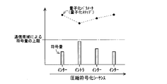
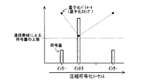
すなわち、圧縮符号化手段100にインター符号化データ24terを生成させる場合、符号化制御手段214は、符号化データ24を復号化装置16へ送信するための有線または無線の伝送路の伝送レートに応じて決まる最大符号量(伝送路の上限伝送レートと、上記許容時間Tとの乗算値で算出される)以下の符号量を設定する。他方、圧縮符号化手段100にイントラ符号化データ24traを生成させる場合、符号化制御手段214は、上記最大符号量よりも多く、かつ、上記最大符号量のN倍(Nは2以上の整数)以下の符号量を設定する。ここでは、Nの値は予め設定されるものとする。
図7の第2段目の例示では、インター符号化データ24terとイントラ符号化データ24traとの符号量(データ量)の相違を、これらのデータ24ter,24traを表す四角形の面積の相違によって表現している。なお、インター符号化データ24terの全てを同じ面積によって図示しているが、これは単に図面の煩雑化を避けるために簡略化した図示に過ぎない。また、図7の第2段目の例示では、符号化データ24を表す四角形の横寸法は、その符号化データ24の生成時間の概略を表している。
上記符号量制御によれば、インター符号化データ24terは、1ピクチャ当たりの許容時間T内に出力を完了可能である。他方、上記最大符号量よりも増量されたイントラ符号化データ24traは、伝送レートの制限から、許容時間T内に出力を完了させることはできない。このため、イントラ符号化データ24traの生成・出力に対しては、許容時間TのN倍の処理時間Ttraが割り当てられる。図7ではN=2の場合、すなわちTtra=T×2の場合が例示されている。
ここで、図7の第2段目には、イントラ符号化データ24traの生成自体は許容時間T内に完了可能であるが、生成された符号化データ24traの出力が伝送レートの制限を受ける結果、イントラ符号化データ24traに関する処理全体に{T×2}の処理時間がかかる場合を例示している。
この例の場合、第m番目のピクチャ32に対応するイントラ符号化データ24traを伝送路へ出力中に、次の第{m+1}番目のピクチャ32の画像データ22が圧縮符号化手段100へ供給される。しかし、圧縮符号化手段100は、第{m+1}番目の入力画像データ22に対しては符号化データ24の生成および出力は行わず、次の第{m+2}番目の入力画像データ22から符号化データ24の生成および出力を再開する。すなわち、第{m+1}番目の入力画像データ22は、符号化データ24の生成および出力について間引きされる。
また、例えば上記N=3の場合であれば、第{m+1}番目および第{m+2}番目のピクチャ32が間引きされる。
つまり、符号化データ24の生成および出力は、イントラ符号化データ24traに対応するピクチャ32に続く{N-1}枚のピクチャ32については行われず、当該{N-1}枚のピクチャ32の次のピクチャ32から再開される。
後続の画像データ22に対する処理不実行は、例えば、イントラ/インター選択手段106が、上記Nの値を予め取得し、間引く枚数{N-1}をカウントし、当該カウント中はイントラ予測データ152とインター予測データ154のいずれも出力しないことによって実現可能である。
あるいは、例えば符号化手段112が、イントラ/インター選択手段106の上記出力制限およびその解除を行ってもよい。
あるいは、例えば、符号化手段112や制御手段200等が、符号化手段112または圧縮符号化手段100に対するデータの入力制限およびその解除を行ってもよい。
<復号化装置16への符号化データ24の入力>
符号化装置14から順次送信される符号化データ24は、復号化装置16によって順次受信される。なお、図7の第3段目に図示されるように、復号化装置16が受信する符号化データ24には、符号化装置14において間引かれた第{m+1}番目のピクチャ32に対応するインター符号化データ24terは含まれていない。
符号化装置14から順次送信される符号化データ24は、復号化装置16によって順次受信される。なお、図7の第3段目に図示されるように、復号化装置16が受信する符号化データ24には、符号化装置14において間引かれた第{m+1}番目のピクチャ32に対応するインター符号化データ24terは含まれていない。
また、図7の第3段目の例示において符号化データ24を表す四角形の面積は、第2段目と同様に、符号量(データ量)の概略を表している。また、図7の第3段目の例示では、符号化データ24を表す四角形の横寸法は、その符号化データ24の受信時間の概略を表している。
符号化装置14における上記符号量制御と装置14,16間の伝送レートとによれば、図7の第3段目に図示されるように、符号化データ24ter,24traはそれぞれ所定時間T,Ttra内に受信を完了可能である。特に増量されたイントラ符号化データ24traの受信は、伝送路の伝送レートの制限を受ける結果、許容時間Tよりも長い時間Ttraがかかる。
なお、図7には、圧縮符号化の開始から(ここでは符号化装置14へ画像データ22が入力された時点から)符号化データ24が復号化装置16へ到達するまでの遅延時間Dを例示している。かかる遅延時間Dには、符号化データ24の生成および出力に費やされる処理時間と、装置14,16間の伝送に費やされる伝送時間とが含まれる。
<復号化>
復号化装置16は、上記のように、入力された符号化データ24に対して復号化を行って復号化データ26を生成する。図7では符号化データ24の入力に対して遅延無く、復号化が開始される場合を例示しているが、かかる例に限定されるものではない。
復号化装置16は、上記のように、入力された符号化データ24に対して復号化を行って復号化データ26を生成する。図7では符号化データ24の入力に対して遅延無く、復号化が開始される場合を例示しているが、かかる例に限定されるものではない。
また、図7の第4段目の例示において符号化データ24を表す四角形の面積は、第2段目および第3段目と同様に、符号量(データ量)の概略を表している。また、図7の第4段目の例示では、符号化データ24を表す四角形の横寸法は、その符号化データ24の復号化に要する処理時間の概略を表している。
図7の第4段目に図示されるように、符号化データ24ter,24traの復号化はそれぞれ所定時間T,Ttra内に完了可能である。特に増量されたイントラ符号化データ24traに関しては、その受信自体に許容時間Tよりも長い時間がかかるため、復号化も許容時間Tよりも長い時間がかかる。
<表示装置18への復号化データ26の出力>
復号化装置16は、上記のように、復号化データ26を順次、表示装置18へ出力する。これにより、各復号化データ26に基づく画像が連続的に表示装置18に表示され、復号化された動画像が得られる。なお、図7には復号化開始から復号化データ26が出力されるまでの間に処理時間Tと同じ長さの遅延がある場合を例示しているが、かかる例に限定されるものではない。
復号化装置16は、上記のように、復号化データ26を順次、表示装置18へ出力する。これにより、各復号化データ26に基づく画像が連続的に表示装置18に表示され、復号化された動画像が得られる。なお、図7には復号化開始から復号化データ26が出力されるまでの間に処理時間Tと同じ長さの遅延がある場合を例示しているが、かかる例に限定されるものではない。
ここで、イントラ符号化データ24traの復号化処理時間Ttraは、インター符号化データ24terの復号化処理時間Tよりも長い。このため、第{m-1}番目のピクチャ32に対応するインター復号化データ26terの出力後に、第m番目のピクチャ32に対応するイントラ復号化データ26terの復号化が終了していない場合が生じうる。
かかる点に鑑み、復号化装置16の出力手段406は、図7の最下段に図示されるように、イントラ復号化データ26traの直前のインター復号化データ26ter、すなわち第{m-1}番目のピクチャ32に対応する復号化データ26terを再度出力する。これにより、第{m-1}番目のピクチャ32に対応する復号化データ26terが再度表示される。
例えばTtra=T×3の場合、復号化装置16は、第{m-1}番目のピクチャ32に対応する復号化データ26terを合計3回連続して出力する。
つまり、イントラ符号化データ24traについての復号化が終了するまで、当該イントラ符号化データ24traの直前に受信したインター符号化データ24terに対応するインター復号化データ26terが繰り返し、表示装置18へ出力される。
なお、同じ復号化データ26terの繰り返し表示は、人の目に静止画像として認識されない時間を限度にするのが好ましい。これは、同じ画像(絵柄)が所定時間を超えて継続すると、人の目には静止画として認識されやすくなり、その結果、動画像としての画質低下に繋がる場合があるからである。当該所定時間は、個人差はあるが、約0.1秒が目安になる。換言すれば、例えば、入力動画像のフレームレートが30フレーム/秒である場合、上記N(Nは2以上の整数)の値として2または3が選定されることが好ましい。
符号化装置14、復号化装置16、システム12およびこれらに採用されている上記各種手法によれば、次の効果を得ることができる。
まず、イントラ符号化データ24traの符号量が、伝送路の伝送レートに基づいて規定される上記最大符号量よりも多く設定される。このため、イントラ符号化データ24traの符号量が、インター符号化データ24terと同様に上記最大符号量以下に設定される場合に比べて、イントラ符号化データを復号化して得られるピクチャの画質を向上させることができる。さらには、その結果として、復号化された動画像全体の画質を向上させることができる。
ここで、図8の模式図に示すように、従来の圧縮符号化ではインター符号化データとイントラ符号化データとのいずれについても、生成される符号量が、伝送レートに応じて決まる最大符号量以下になるように、量子化パラメータが制御されていた。
これに対し、符号化装置14では、図9の模式図に示すように、イントラ符号化データについては、上記最大符号量を超える符号量が許容される。但し、伝送レートによる出力制限を受けるため、伝送路への出力完了にはインター符号化データよりも時間がかかる。
なお、図8および図9にはインター符号化の符号量が変動している場合を例示している。一般に発生符号量は絵柄(画像の内容)にも依存するため、符号量を一定化するのは非常に困難である。従ってここで例示したのは、通信帯域による符号量の上限以下でできるだけ高画質、すなわち高符号量を狙って符号化した結果の一例である。
また、イントラ符号化データ24traに対応するピクチャ32に続く{N-1}枚のピクチャ32については、符号化データ24の生成および出力が間引かれるため、伝送路へ出力されるデータ量(符号量)を抑制することができる。伝送レートによる制限に鑑みれば、上記増量されたイントラ符号化データ24traの出力完了のためには、上記{N-1}枚のピクチャ分の許容時間Tも費やされる。したがって、上記{N-1}枚のピクチャ32を間引かない場合には、伝送路へのデータ出力が順次遅延していき、さらにはイントラ符号化データ24traの出力の度に遅延が累積していくことになる。これに対し、上記の間引き手法によれば、そのような出力遅延および遅延累積を防止することができる。
ところで、図7の第2段目には、上記のように、イントラ符号化データ24traの生成自体は許容時間T内に完了可能である態様を例示した。かかる例の場合、図10の第2段目に破線で示すように、上記では間引かれていた第{m+1}番目のピクチャ32に対してインター符号化を行うことも可能である。しかし、生成されたインター符号化データ24terを出力する場合には、上記のように出力遅延および遅延累積が生じてしまう。
このため、伝送路へ出力する予定のない符号化データ24については、処理量削減のため、図7の例のように、その生成さえも行わないのが好ましい。なお、処理量削減の結果、省電力化等を図ることができる。
また、圧縮符号化手段100が上記のようにイントラ符号化データ24traの生成自体は許容時間T内に完了可能な性能を有する場合でも、伝送レートの都合で出力完了までに長い時間Ttraがかかるのであれば、イントラ符号化データ24traの生成時間を許容時間Tよりも長くしてもよい(図11参照)。
つまり、イントラ符号化データ24traに関する処理を全体的に、許容時間Tよりも長く、かつ、許容時間TのN倍の時間以下の処理時間Ttraをかけて行えばよい。かかる態様によっても、イントラ符号化データ24traを上記最大符号量を超える符号量で以て生成可能であり、かつ、そのように増量されたイントラ符号化データ24traを伝送レートの制限に従いつつも伝送路へ出力完了可能である。
これによれば、図7の例に比べて、圧縮符号化手段100の処理負荷を低減することができる。また、処理負荷低減に伴って圧縮符号化手段100に高性能な構成を採用する必要性が低くなるため、低コスト化、省電力化等を図ることができる。
上記では、イントラ符号化データ24traにはインター符号化データ24terよりも長い復号化時間が必要になるところ、イントラ符号化データ24traの復号化が終了するまでの間は直前のインター符号化データ24terを復号化した画像が繰り返し表示される。このため、復号化した動画像において画像の欠損(例えば全面黒表示の画像が割り込む)が生じないようにすることができる。画像欠損の防止、さらには画像欠損に起因した表示不具合(例えば画像欠損の存在により画像がちらつく等)の防止により、動画像の画質を向上させることができる。
ところで、上記では、伝送レートに制約がある場合に、イントラ符号化データ24traの増量を実現しうる各種態様を例示した。このうちの図11の態様を応用すれば、圧縮符号化手段100の性能(例えば処理速度)に制約がある場合であっても、イントラ符号化データ24traの増量を実現可能である。
具体的には、圧縮符号化手段100は、イントラ符号化データ24traについての所定処理(生成および伝送路への出力が含まれる)を、許容時間Tよりも長く、かつ、許容時間TのN倍の時間以下の処理時間をかけて行えば良い。
これによれば、イントラ符号化データ24traの符号量を、1ピクチャ当たりの許容時間T内で生成・出力可能な最大符号量よりも、多くすることができる。このため、イントラ符号化データ24traに許容時間Tしか割り当てない場合に比べて、イントラ符号化データ24traを復号化して得られるピクチャの画質を向上させることができる。さらには、その結果として、復号化された動画像全体の画質を向上させることができる。
また、上記増量されたイントラ符号化データ24traを許容時間T内で生成させる場合に比べて、圧縮符号化手段100の処理負荷が少なくて済む。このため、圧縮符号化手段100に高性能な構成を採用する必要性が低くなり、処理速度の遅い構成等を採用することができる。その結果、低コスト化、省電力化等を図ることができる。
さて、上記特許文献1に記載の符号化方法では、シーンチェンジ直後の画像をIピクチャとして符号化するとともに新しいGOP(Group Of Picture)の先頭に設定する。また、かかる符号化方法において、シーンチェンジの検出結果と、過去に符号化した結果の蓄積データとに基づいて、ピクチャタイプ(I,P,Bピクチャの種別)を決定し、決定されたピクチャタイプに応じて符号化ビットレートを制御する。また、かかる符号化方法において、GOP長を可変にする手法と、GOP長は固定し、当該固定長における各ピクチャの情報量を配分する手法とが紹介されている。
しかし、特許文献1には、符号化装置14等に採用されている上記各種手法は開示されていない。例えば、伝送路の伝送レートを要因とする制約や、圧縮符号化手段100の性能を要因とする制約を満足しつつイントラ符号化データ24traの符号量を増大させて、高画質化を図る手法は、特許文献1に開示されていない。また、例えば、イントラ符号化の実行中に入力される画像データ22を間引く手法も、特許文献1には開示されていない。また、イントラ復号化データ26traの直前のインター復号化データ26terを繰り返し表示装置向けに出力する手法も、特許文献1には開示されていない。
<変形例1>
図12に、シングルバッファ構成を採用した復号化装置16Bを概説するブロック図を示す。この復号化装置16Bは、上記の復号化装置16(図5参照)において2つのバッファ404,406を1つのバッファ410に変更した構成を有している。
図12に、シングルバッファ構成を採用した復号化装置16Bを概説するブロック図を示す。この復号化装置16Bは、上記の復号化装置16(図5参照)において2つのバッファ404,406を1つのバッファ410に変更した構成を有している。
シングルバッファ構成では、イントラ復号化データ26traとインター復号化データ26terの両方ともバッファ410へ格納される。このため、出力手段406が、復号化手段400に対する書き込み許可/禁止を信号452で指示することによって、必要なデータ26が上書きされて消失してしまうのを防止している。
具体的には、バッファ410において、表示装置18への出力(上記の繰り返し出力を含む)が済んだ復号化データ26の記憶領域は上書きをしても支障がないので、出力手段406は、そのような上書き許容領域の発生、あるいはさらにその領域の位置指定を書き込み許可信号452によって、復号化手段400へ通知する。復号化手段400は、当該信号452の受信により、復号化を行って、その許容領域へ復号化データ26を書き込む(図13の模式図参照)。
なお、書き込み許容信号452は、復号化データ26の全体を格納可能な大きさの記憶領域が発生した時点で発信されてもよいし、あるいは、復号化データ26を部分的に(例えばブロック単位で)格納可能な大きさの記憶領域が発生した時点で発信されてもよい。
復号化装置16Bによっても、上記各種効果を得ることができる。
<変形例2>
上記では、同じ入力画像データ22に対して、イントラ予測データ152とインター予測データ154の両方を生成する場合を例示した(図4参照)。これに対し、制御手段200がイントラ符号化要求信号250(図3参照)の受信/不受信に従ってイントラ予測手段102とインター予測手段104とのうちのいずれか一方のみを制御することによって、イントラ予測データ152とインター予測データ154のうちの一方のみを生成するように変形することも可能である。かかる場合も上記各種効果を得ることができる。
上記では、同じ入力画像データ22に対して、イントラ予測データ152とインター予測データ154の両方を生成する場合を例示した(図4参照)。これに対し、制御手段200がイントラ符号化要求信号250(図3参照)の受信/不受信に従ってイントラ予測手段102とインター予測手段104とのうちのいずれか一方のみを制御することによって、イントラ予測データ152とインター予測データ154のうちの一方のみを生成するように変形することも可能である。かかる場合も上記各種効果を得ることができる。
<変形例3>
ところで、上記のように、イントラ符号化は、他のピクチャ32に依拠することなく、対象とするピクチャ32を符号化する処理である。このため、イントラ符号化には、イントラ予測を行わずに、入力画像データ22をそのまま符号化する場合も含まれる。
ところで、上記のように、イントラ符号化は、他のピクチャ32に依拠することなく、対象とするピクチャ32を符号化する処理である。このため、イントラ符号化には、イントラ予測を行わずに、入力画像データ22をそのまま符号化する場合も含まれる。
かかる点に鑑みた符号化装置14Bのブロック図を図14に例示する。符号化装置14Bでは、図4に例示した構成からイントラ予測手段102が取り除かれ、入力画像データ22がイントラ/インター選択手段106へ入力され、イントラ/インター選択手段106から入力画像データ22とインター予測データ154とうちのいずれか一方が出力される。符号化装置14Bのその他の構成は、上記の符号化装置14(図4参照)と同様である。符号化装置14Bによっても、上記各種効果を得ることができる。
この発明は詳細に説明されたが、上記した説明は、すべての局面において、例示であって、この発明がそれに限定されるものではない。例示されていない無数の変形例が、この発明の範囲から外れることなく想定され得るものと解される。
12 画像符号化復号化システム
14,14B 画像符号化装置
16,16B 画像復号化装置
18 表示装置
22 画像データ
24 符号化データ
24ter インター符号化データ
24tra イントラ符号化データ
26 復号化データ
26ter インター復号化データ
26tra イントラ復号化データ
30 動画像
32 ピクチャ
100 圧縮符号化手段
200 制御手段
400 復号化手段
406 出力手段
T,Ttra 処理時間
14,14B 画像符号化装置
16,16B 画像復号化装置
18 表示装置
22 画像データ
24 符号化データ
24ter インター符号化データ
24tra イントラ符号化データ
26 復号化データ
26ter インター復号化データ
26tra イントラ復号化データ
30 動画像
32 ピクチャ
100 圧縮符号化手段
200 制御手段
400 復号化手段
406 出力手段
T,Ttra 処理時間
Claims (14)
- 入力動画像を構成する各ピクチャの画像データ(22)に圧縮符号化を行ってピクチャごとにインター符号化データ(24ter)とイントラ符号化データ(24tra)とのうちのいずれか一方を生成する生成処理と、生成された符号化データ(24)を有線または無線の伝送路へ出力する出力処理とを含んだ所定処理を行う、圧縮符号化手段(100)と、
前記圧縮符号化手段に対し、前記インター符号化データと前記イントラ符号化データとのうちのいずれを生成させるかについての制御と、前記圧縮符号化によって生成される符号量の制御とを行う、制御手段(200)と
を備え、
前記制御手段は、
前記圧縮符号化手段に前記インター符号化データを生成させる場合、前記伝送路の上限伝送レートと、前記入力動画像のピクチャレートに基づいて1ピクチャ当たりに割り当てられる許容時間との乗算値で与えられる最大符号量以下の符号量を設定し、
前記圧縮符号化手段に前記イントラ符号化データを生成させる場合、前記最大符号量よりも多く前記最大符号量のN倍(Nは2以上の整数)以下の符号量を設定する、
画像符号化装置(14,14B)。 - 請求項1に記載の画像符号化装置であって、
前記圧縮符号化手段は、
前記イントラ符号化データについての前記所定処理を、前記許容時間よりも長く前記許容時間の前記N倍の時間以下の処理時間をかけて行う、
画像符号化装置(14,14B)。 - 請求項1に記載の画像符号化装置であって、
前記圧縮符号化手段は、
前記イントラ符号化データに対応する前記ピクチャに続く{N-1}枚のピクチャについては、前記所定処理のうちの少なくとも前記出力処理を行わない、
画像符号化装置(14,14B)。 - 請求項3に記載の画像符号化装置であって、
前記圧縮符号化手段は、
前記{N-1}枚のピクチャについては、前記所定処理のうちで前記生成処理も行わない、
画像符号化装置(14,14B)。 - 入力動画像を構成する各ピクチャの画像データ(22)に圧縮符号化を行ってピクチャごとにインター符号化データ(24ter)とイントラ符号化データ(24tra)とのうちのいずれか一方を生成する生成処理と、生成された符号化データ(24)を有線または無線の伝送路へ出力する出力処理とを含んだ所定処理を行う、圧縮符号化手段(100)と、
前記圧縮符号化手段に対し、前記インター符号化データと前記イントラ符号化データとのうちのいずれを生成させるかについての制御と、前記圧縮符号化によって生成される符号量の制御とを行う、制御手段(200)と
を備え、
前記圧縮符号化手段は、
前記イントラ符号化データについての前記所定処理を、前記入力動画像のピクチャレートに基づいて1ピクチャ当たりに割り当てられる許容時間よりも長く前記許容時間のN倍(Nは2以上の整数)の時間以下の処理時間をかけて行う、
画像符号化装置(14,14B)。 - 請求項5に記載の画像符号化装置であって、
前記圧縮符号化手段は、
前記イントラ符号化データに対応する前記ピクチャに続く{N-1}枚のピクチャについては、前記所定処理を行わない、
画像符号化装置(14,14B)。 - 請求項1ないし請求項6のうちのいずれか1項に記載の画像符号化装置(14,14B)と、
前記画像符号化装置と前記有線または無線の伝送路を介して通信可能に設けられた画像復号化装置(16,16B)と
を備え、
前記画像復号化装置は、
前記画像符号化装置から前記符号化データを受信し、前記符号化データに基づいて、前記圧縮符号化に対応する復号化を行うことによって復号化データ(26)を生成する、復号化手段(400)と、
前記復号化によって順次生成される前記復号化データを表示装置向けに順次出力する出力手段(406)と
を含んでおり、
前記出力手段は、
前記イントラ符号化データについての前記復号化が終了するまで、当該イントラ符号化データの直前に受信した前記インター符号化データに対応するインター復号化データ(26ter)を繰り返し表示装置向けに出力する、
画像符号化復号化システム(12)。 - (a)入力動画像を構成する各ピクチャの画像データ(22)に圧縮符号化を行ってピクチャごとにインター符号化データ(24ter)とイントラ符号化データ(24tra)とのうちのいずれか一方を生成する生成処理と、生成された符号化データ(24)を有線または無線の伝送路へ出力する出力処理とを含んだ所定処理を行うステップと、
(b)前記ステップ(a)に関して、前記インター符号化データと前記イントラ符号化データとのうちのいずれを生成させるかについての制御と、前記圧縮符号化によって生成される符号量の制御とを行うステップと
を備え、
前記ステップ(b)では、
前記ステップ(a)で前記インター符号化データを生成させる場合、前記伝送路の上限伝送レートと、前記入力動画像のピクチャレートに基づいて1ピクチャ当たりに割り当てられる許容時間との乗算値で与えられる最大符号量以下の符号量を設定し、
前記ステップ(a)で前記イントラ符号化データを生成させる場合、前記最大符号量よりも多く前記最大符号量のN倍(Nは2以上の整数)以下の符号量を設定する、
画像符号化方法。 - 請求項8に記載の画像符号化方法であって、
前記ステップ(a)では、
前記イントラ符号化データについての前記所定処理を、前記許容時間よりも長く前記許容時間の前記N倍の時間以下の処理時間をかけて行う、
画像符号化方法。 - 請求項8に記載の画像符号化方法であって、
前記ステップ(a)では、
前記イントラ符号化データに対応する前記ピクチャに続く{N-1}枚のピクチャについては、前記所定処理のうちの少なくとも前記出力処理を行わない、
画像符号化方法。 - 請求項10に記載の画像符号化方法であって、
前記ステップ(a)では、
前記{N-1}枚のピクチャについては、前記所定処理のうちで前記生成処理も行わない、
画像符号化方法。 - (a)入力動画像を構成する各ピクチャの画像データ(22)に圧縮符号化を行ってピクチャごとにインター符号化データ(24ter)とイントラ符号化データ(24tra)とのうちのいずれか一方を生成する生成処理と、生成された符号化データ(24)を有線または無線の伝送路へ出力する出力処理とを含んだ所定処理を行うステップと、
(b)前記ステップ(a)に関して、前記インター符号化データと前記イントラ符号化データとのうちのいずれを生成させるかについての制御と、前記圧縮符号化によって生成される符号量の制御とを行うステップと
を備え、
前記ステップ(a)では、
前記イントラ符号化データについての前記所定処理を、前記入力動画像のピクチャレートに基づいて1ピクチャ当たりに割り当てられる許容時間よりも長く前記許容時間のN倍(Nは2以上の整数)の時間以下の処理時間をかけて行う、
画像符号化方法。 - 請求項12に記載の画像符号化方法であって、
前記ステップ(a)では、
前記イントラ符号化データに対応する前記ピクチャに続く{N-1}枚のピクチャについては、前記所定処理を行わない、
画像符号化方法。 - (c)請求項8ないし請求項13のうちのいずれか1項に記載の画像符号化方法によって生成された前記符号化データを、前記有線または無線の伝送路を介して受信するステップと、
(d)前記ステップ(c)で受信した前記符号化データに基づいて、前記圧縮符号化に対応する復号化を行うことによって復号化データ(26)を生成するステップと、
(e)前記ステップ(d)によって順次生成される前記復号化データに基づいて表示装置に画像表示を行わせるステップと
を備え、
前記ステップ(e)では、
前記ステップ(d)において前記イントラ符号化データについての前記復号化が終了するまで、当該イントラ符号化データの直前に受信した前記インター符号化データに対応するインター復号化データ(26ter)を繰り返し用いて前記画像表示を行う、
画像表示方法。
Priority Applications (1)
| Application Number | Priority Date | Filing Date | Title |
|---|---|---|---|
| US13/520,306 US20120307881A1 (en) | 2010-03-03 | 2010-11-09 | Image coding device, image coding/decoding system, image coding method, and image display method |
Applications Claiming Priority (2)
| Application Number | Priority Date | Filing Date | Title |
|---|---|---|---|
| JP2010046223A JP5694674B2 (ja) | 2010-03-03 | 2010-03-03 | 画像符号化装置、画像符号化復号化システム、画像符号化方法、画像表示方法 |
| JP2010-046223 | 2010-03-03 |
Publications (1)
| Publication Number | Publication Date |
|---|---|
| WO2011108146A1 true WO2011108146A1 (ja) | 2011-09-09 |
Family
ID=44541822
Family Applications (1)
| Application Number | Title | Priority Date | Filing Date |
|---|---|---|---|
| PCT/JP2010/069939 WO2011108146A1 (ja) | 2010-03-03 | 2010-11-09 | 画像符号化装置、画像符号化復号化システム、画像符号化方法、画像表示方法 |
Country Status (3)
| Country | Link |
|---|---|
| US (1) | US20120307881A1 (ja) |
| JP (1) | JP5694674B2 (ja) |
| WO (1) | WO2011108146A1 (ja) |
Cited By (1)
| Publication number | Priority date | Publication date | Assignee | Title |
|---|---|---|---|---|
| CN103618903A (zh) * | 2013-12-10 | 2014-03-05 | 天津大学 | 高速低功耗无线传感网络视频压缩采样方法及装置 |
Families Citing this family (3)
| Publication number | Priority date | Publication date | Assignee | Title |
|---|---|---|---|---|
| JP2014017554A (ja) * | 2012-07-05 | 2014-01-30 | Canon Inc | 画像符号化装置 |
| CN107534780A (zh) * | 2015-02-25 | 2018-01-02 | 瑞典爱立信有限公司 | 视频中的帧间画面的编码和解码 |
| JP7210944B2 (ja) * | 2018-09-05 | 2023-01-24 | 富士通株式会社 | 映像符号化装置、映像符号化方法および映像符号化プログラム |
Citations (3)
| Publication number | Priority date | Publication date | Assignee | Title |
|---|---|---|---|---|
| JPH07203458A (ja) * | 1993-12-27 | 1995-08-04 | Olympus Optical Co Ltd | 動画像符号化装置 |
| JP2006287864A (ja) * | 2005-04-05 | 2006-10-19 | Nippon Hoso Kyokai <Nhk> | 符号化装置および符号化プログラム |
| JP2009290712A (ja) * | 2008-05-30 | 2009-12-10 | Mega Chips Corp | トランスコーダ |
Family Cites Families (16)
| Publication number | Priority date | Publication date | Assignee | Title |
|---|---|---|---|---|
| JP2871316B2 (ja) * | 1992-07-10 | 1999-03-17 | 日本ビクター株式会社 | 動画像符号化装置 |
| US6058459A (en) * | 1996-08-26 | 2000-05-02 | Stmicroelectronics, Inc. | Video/audio decompression/compression device including an arbiter and method for accessing a shared memory |
| US20020154694A1 (en) * | 1997-03-21 | 2002-10-24 | Christopher H. Birch | Bit stream splicer with variable-rate output |
| JP3551887B2 (ja) * | 2000-04-03 | 2004-08-11 | 日本電気株式会社 | 動画像再生方法および装置 |
| JP2002125226A (ja) * | 2000-10-17 | 2002-04-26 | Matsushita Electric Ind Co Ltd | フレームレート制御方法及び画像伝送装置 |
| US20020087976A1 (en) * | 2000-12-28 | 2002-07-04 | Kaplan Marc P. | System and method for distributing video with targeted advertising using switched communication networks |
| US7034890B2 (en) * | 2001-04-13 | 2006-04-25 | Ati Technologies, Inc. | Method and apparatus for updating a computer system clock from a real time television signal |
| US20030204630A1 (en) * | 2002-04-29 | 2003-10-30 | The Boeing Company | Bandwidth-efficient and secure method to combine multiple live events to multiple exhibitors |
| US7418037B1 (en) * | 2002-07-15 | 2008-08-26 | Apple Inc. | Method of performing rate control for a compression system |
| JP4118232B2 (ja) * | 2003-12-19 | 2008-07-16 | 三菱電機株式会社 | 映像データ処理方法および映像データ処理装置 |
| KR100619041B1 (ko) * | 2004-07-22 | 2006-09-01 | 삼성전자주식회사 | 비디오 동기화 장치 및 비디오 동기화 방법 |
| US20090080866A1 (en) * | 2006-03-27 | 2009-03-26 | Nds Limited | Video Substitution System |
| US7684332B2 (en) * | 2006-08-22 | 2010-03-23 | Embarq Holdings Company, Llc | System and method for adjusting the window size of a TCP packet through network elements |
| US7456760B2 (en) * | 2006-09-11 | 2008-11-25 | Apple Inc. | Complexity-aware encoding |
| KR101418950B1 (ko) * | 2006-12-12 | 2014-07-17 | 밴트릭스 코오퍼레이션 | 비디오 코딩 표준에 대한 개선된 비디오율 제어 |
| US8259814B2 (en) * | 2008-11-12 | 2012-09-04 | Cisco Technology, Inc. | Processing of a video program having plural processed representations of a single video signal for reconstruction and output |
-
2010
- 2010-03-03 JP JP2010046223A patent/JP5694674B2/ja not_active Expired - Fee Related
- 2010-11-09 WO PCT/JP2010/069939 patent/WO2011108146A1/ja active Application Filing
- 2010-11-09 US US13/520,306 patent/US20120307881A1/en not_active Abandoned
Patent Citations (3)
| Publication number | Priority date | Publication date | Assignee | Title |
|---|---|---|---|---|
| JPH07203458A (ja) * | 1993-12-27 | 1995-08-04 | Olympus Optical Co Ltd | 動画像符号化装置 |
| JP2006287864A (ja) * | 2005-04-05 | 2006-10-19 | Nippon Hoso Kyokai <Nhk> | 符号化装置および符号化プログラム |
| JP2009290712A (ja) * | 2008-05-30 | 2009-12-10 | Mega Chips Corp | トランスコーダ |
Cited By (2)
| Publication number | Priority date | Publication date | Assignee | Title |
|---|---|---|---|---|
| CN103618903A (zh) * | 2013-12-10 | 2014-03-05 | 天津大学 | 高速低功耗无线传感网络视频压缩采样方法及装置 |
| CN103618903B (zh) * | 2013-12-10 | 2017-01-04 | 天津大学 | 高速低功耗无线传感网络视频压缩采样方法 |
Also Published As
| Publication number | Publication date |
|---|---|
| US20120307881A1 (en) | 2012-12-06 |
| JP2011182284A (ja) | 2011-09-15 |
| JP5694674B2 (ja) | 2015-04-01 |
Similar Documents
| Publication | Publication Date | Title |
|---|---|---|
| JP5174958B2 (ja) | ビデオのコーダとデコーダとの同時最適化のための方法およびシステム | |
| US20070199011A1 (en) | System and method for high quality AVC encoding | |
| US20030095603A1 (en) | Reduced-complexity video decoding using larger pixel-grid motion compensation | |
| US20010046263A1 (en) | Video encoding apparatus that adjusts code amount by skipping encoding of image data | |
| US9392278B2 (en) | Image encoding or decoding apparatus, system, method, and storage medium for encoding or decoding a plurality of images in parallel | |
| WO2010106670A1 (ja) | 画像符号化装置、画像符号化制御方法および画像符号化プログラム | |
| US8170375B2 (en) | Image processing apparatus and method for controlling the same | |
| CN101960858A (zh) | 运动图像编码装置、摄像装置以及运动图像编码方法 | |
| KR20140143328A (ko) | 디지털 비디오 데이터를 인코딩하는 방법 | |
| JP2015171114A (ja) | 動画像符号化装置 | |
| US9386310B2 (en) | Image reproducing method, image reproducing device, image reproducing program, imaging system, and reproducing system | |
| JP2007507128A (ja) | 参照ピクチャのリフレッシュを遅延させて行うビデオ画像の符号化および復号化 | |
| WO2011108146A1 (ja) | 画像符号化装置、画像符号化復号化システム、画像符号化方法、画像表示方法 | |
| US20070014364A1 (en) | Video coding method for performing rate control through frame dropping and frame composition, video encoder and transcoder using the same | |
| JP2003348597A (ja) | 画像符号化装置および画像符号化方法 | |
| WO2010100991A1 (ja) | 動画像ストリーム復号装置及びその制御方法並びにプログラム、記録媒体 | |
| JP2002199392A (ja) | 映像符号化方法および装置 | |
| US20110051815A1 (en) | Method and apparatus for encoding data and method and apparatus for decoding data | |
| JP4911625B2 (ja) | 画像処理装置、およびそれを搭載した撮像装置 | |
| KR101678138B1 (ko) | 동화상 부호화 방법, 장치 및 프로그램 | |
| JP6182888B2 (ja) | 画像符号化装置 | |
| JP4700992B2 (ja) | 画像処理装置 | |
| JP6874844B2 (ja) | 動画像符号化装置、動画像符号化方法、及び、動画像符号化プログラム | |
| WO2013073422A1 (ja) | 動画像符号化装置 | |
| JP2009118096A (ja) | 画像符号化装置及びその制御方法、コンピュータプログラム |
Legal Events
| Date | Code | Title | Description |
|---|---|---|---|
| 121 | Ep: the epo has been informed by wipo that ep was designated in this application |
Ref document number: 10847043 Country of ref document: EP Kind code of ref document: A1 |
|
| WWE | Wipo information: entry into national phase |
Ref document number: 13520306 Country of ref document: US |
|
| NENP | Non-entry into the national phase |
Ref country code: DE |
|
| 122 | Ep: pct application non-entry in european phase |
Ref document number: 10847043 Country of ref document: EP Kind code of ref document: A1 |