WO2011108146A1 - Dispositif de codage d'image, système de codage/décodage d'image, procédé de codage d'image, et procédé d'affichage d'image - Google Patents
Dispositif de codage d'image, système de codage/décodage d'image, procédé de codage d'image, et procédé d'affichage d'image Download PDFInfo
- Publication number
- WO2011108146A1 WO2011108146A1 PCT/JP2010/069939 JP2010069939W WO2011108146A1 WO 2011108146 A1 WO2011108146 A1 WO 2011108146A1 JP 2010069939 W JP2010069939 W JP 2010069939W WO 2011108146 A1 WO2011108146 A1 WO 2011108146A1
- Authority
- WO
- WIPO (PCT)
- Prior art keywords
- intra
- image
- data
- picture
- encoded data
- Prior art date
Links
Images


Classifications
-
- H—ELECTRICITY
- H04—ELECTRIC COMMUNICATION TECHNIQUE
- H04N—PICTORIAL COMMUNICATION, e.g. TELEVISION
- H04N19/00—Methods or arrangements for coding, decoding, compressing or decompressing digital video signals
- H04N19/60—Methods or arrangements for coding, decoding, compressing or decompressing digital video signals using transform coding
- H04N19/61—Methods or arrangements for coding, decoding, compressing or decompressing digital video signals using transform coding in combination with predictive coding
-
- H—ELECTRICITY
- H04—ELECTRIC COMMUNICATION TECHNIQUE
- H04N—PICTORIAL COMMUNICATION, e.g. TELEVISION
- H04N19/00—Methods or arrangements for coding, decoding, compressing or decompressing digital video signals
- H04N19/10—Methods or arrangements for coding, decoding, compressing or decompressing digital video signals using adaptive coding
- H04N19/102—Methods or arrangements for coding, decoding, compressing or decompressing digital video signals using adaptive coding characterised by the element, parameter or selection affected or controlled by the adaptive coding
- H04N19/115—Selection of the code volume for a coding unit prior to coding
-
- H—ELECTRICITY
- H04—ELECTRIC COMMUNICATION TECHNIQUE
- H04N—PICTORIAL COMMUNICATION, e.g. TELEVISION
- H04N19/00—Methods or arrangements for coding, decoding, compressing or decompressing digital video signals
- H04N19/10—Methods or arrangements for coding, decoding, compressing or decompressing digital video signals using adaptive coding
- H04N19/134—Methods or arrangements for coding, decoding, compressing or decompressing digital video signals using adaptive coding characterised by the element, parameter or criterion affecting or controlling the adaptive coding
- H04N19/157—Assigned coding mode, i.e. the coding mode being predefined or preselected to be further used for selection of another element or parameter
- H04N19/159—Prediction type, e.g. intra-frame, inter-frame or bidirectional frame prediction
-
- H—ELECTRICITY
- H04—ELECTRIC COMMUNICATION TECHNIQUE
- H04N—PICTORIAL COMMUNICATION, e.g. TELEVISION
- H04N19/00—Methods or arrangements for coding, decoding, compressing or decompressing digital video signals
- H04N19/10—Methods or arrangements for coding, decoding, compressing or decompressing digital video signals using adaptive coding
- H04N19/169—Methods or arrangements for coding, decoding, compressing or decompressing digital video signals using adaptive coding characterised by the coding unit, i.e. the structural portion or semantic portion of the video signal being the object or the subject of the adaptive coding
- H04N19/17—Methods or arrangements for coding, decoding, compressing or decompressing digital video signals using adaptive coding characterised by the coding unit, i.e. the structural portion or semantic portion of the video signal being the object or the subject of the adaptive coding the unit being an image region, e.g. an object
- H04N19/176—Methods or arrangements for coding, decoding, compressing or decompressing digital video signals using adaptive coding characterised by the coding unit, i.e. the structural portion or semantic portion of the video signal being the object or the subject of the adaptive coding the unit being an image region, e.g. an object the region being a block, e.g. a macroblock
Definitions
- the present invention relates to an image encoding device, an image encoding / decoding system, an image encoding method, and an image display method.
- H.264 As a video encoding method, for example, H.264 is used.
- H.264, MPEG (Moving Picture Experts Group) -2, MPEG-4, and the like are known.
- data compression is often performed at the time of encoding.
- encoding and “compression encoding” may be used synonymously.
- the present specification basically uses the same terms.
- Intra coding is a technique for coding a picture that constitutes a moving picture using only that picture regardless of other pictures. Therefore, an intra-coded picture (hereinafter also referred to as an intra-coded picture) can be decoded alone. Note that an intra-coded picture is also referred to as an I picture (Intra-Picture).
- inter coding is a method of performing inter prediction (also referred to as inter-picture prediction, inter-picture prediction, etc.) using correlation with other pictures, and encoding the prediction result, that is, a predicted picture. is there.
- Inter prediction may be performed between predicted pictures for other pictures.
- An inter-encoded picture (hereinafter also referred to as an inter-encoded picture) cannot be decoded unless a picture (referred to as a reference picture or a reference screen) referred to at the time of inter prediction is used.
- the inter-coded pictures include a P picture (Predictive-Picture) coded based on the front picture in the moving image sequence and a B picture (Bidirectional) coded based on the front and rear pictures.
- P picture Predictive-Picture
- B picture Bidirectional coded based on the front and rear pictures.
- predictive-picture There are two types: predictive-picture.
- intra coding a picture to be coded is divided into a plurality of blocks (or macro blocks), and is also referred to as intra prediction (intra-screen prediction, intra-picture prediction, etc.) using the correlation between the blocks. May be performed.
- the amount of encoded data to be generated (in other words, the amount of code) is controlled so as to be within the limits of the communication band of the transmission path (in other words, the transmission rate).
- an intra-coded picture has a larger code amount than an inter-coded picture. For this reason, when the amount of code is reduced in order to meet the above various restrictions, the amount of reduction is larger for intra-coded pictures than for inter-coded pictures.
- the image coding apparatus performs compression coding on image data of each picture constituting an input moving image, and selects either inter-coded data or intra-coded data for each picture.
- a compression encoding unit that performs a predetermined process including a generation process for generating one of them and an output process for outputting the generated encoded data to a wired or wireless transmission path, and the compression encoding unit, Control means for controlling which of the inter-encoded data and the intra-encoded data is to be generated and control of the amount of code generated by the compression encoding;
- the compression encoding means When the compression encoding means generates the inter-encoded data, it is 1 pixel based on the upper limit transmission rate of the transmission path and the picture rate of the input moving picture.
- the maximum code amount is larger than the maximum code amount.
- a code amount equal to or less than N times (N is an integer of 2 or more) is set.
- the image encoding device is the image encoding device according to the first aspect, wherein the compression encoding means performs the predetermined processing on the intra-encoded data, It takes a processing time longer than the allowable time and not more than N times the allowable time.
- An image encoding device is the image encoding device according to the first or second aspect, wherein the compression encoding means includes the picture corresponding to the intra-encoded data. For ⁇ N-1 ⁇ pictures following the above, at least the output processing of the predetermined processing is not performed.
- An image encoding device is the image encoding device according to the third aspect, wherein the compression encoding means is configured to perform the above processing for the ⁇ N-1 ⁇ pictures. The generation process is not performed in the predetermined process.
- the image coding apparatus performs compression coding on the image data of each picture constituting the input moving image, and selects either inter-coded data or intra-coded data for each picture.
- a compression encoding means for performing a predetermined process including a generation process for generating one and an output process for outputting the generated encoded data to a wired or wireless transmission path; and Control means for controlling whether to generate inter-encoded data or intra-encoded data, and controlling the amount of code generated by the compression encoding, the compression encoding
- the means performs the predetermined processing on the intra-coded data more than an allowable time allocated per picture based on a picture rate of the input moving image. Ku N times the allowable time (N is an integer of 2 or more) performed over a period of time following the processing time.
- the image coding apparatus is the image coding apparatus according to the fifth aspect, wherein the compression coding means follows the picture corresponding to the intra-coded data ⁇ The predetermined process is not performed for N-1 ⁇ pictures.
- An image encoding / decoding system includes an image encoding apparatus according to any one of the first to sixth aspects, the image encoding apparatus, and the wired or wireless An image decoding device provided to be communicable via a transmission path, the image decoding device receiving the encoded data from the image encoding device, and based on the encoded data, the compression Decoding means for generating decoded data by performing decoding corresponding to encoding, and output means for sequentially outputting the decoded data sequentially generated by the decoding to a display device
- the output means performs inter decoding corresponding to the inter encoded data received immediately before the intra encoded data until the decoding of the intra encoded data is completed. And it outputs the data to the repeated display device for the.
- the image coding method includes (a) compression coding on image data of each picture constituting the input moving image, and the inter coding data and the intra coding data for each picture.
- the code amount is larger than the maximum code amount.
- a code amount not more than N times the maximum code amount (N is an integer of 2 or more) is set.
- An image encoding method is the image encoding method according to the eighth aspect, wherein in the step (a), the predetermined process for the intra-encoded data is performed by It takes a processing time longer than the allowable time and not more than N times the allowable time.
- the image coding method according to the tenth aspect is the image coding method according to the eighth or ninth aspect, wherein in the step (a), the picture corresponding to the intra-coded data is used. For ⁇ N-1 ⁇ pictures following the above, at least the output processing of the predetermined processing is not performed.
- the image coding method according to the eleventh aspect is the image coding method according to the tenth aspect described above, wherein in the step (a), the ⁇ N-1 ⁇ pictures are The generation process is not performed in the predetermined process.
- the image encoding method includes (a) compression encoding the image data of each picture constituting the input moving image, and the inter encoded data and the intra encoded data for each picture.
- the image coding method according to the thirteenth aspect is the image coding method according to the twelfth aspect described above, and the step (a) follows the picture corresponding to the intra-coded data ⁇
- the predetermined process is not performed for N-1 ⁇ pictures.
- An image display method is the wired or wireless transmission of the encoded data generated by the image encoding method according to any one of the eighth to thirteenth aspects.
- the intra coding is performed in the step (d). Until the decoding of data is completed, the inter-decoded data corresponding to the inter-encoded data received immediately before the intra-encoded data. The performing the image display by using repeatedly.
- the code amount of the intra-coded data is set to be larger than the maximum code amount defined based on the transmission rate of the transmission path. For this reason, the picture quality of a picture obtained by decoding intra-encoded data can be improved as compared with a case where the code amount of intra-encoded data is set to the maximum code amount or less. Furthermore, as a result, the image quality of the entire decoded moving image can be improved.
- intra-encoded data can be generated with a code amount exceeding the maximum code amount, and the intra-encoded data thus increased is transmitted at the transmission rate. It is possible to provide a form capable of completing output to the transmission line while complying with the restrictions. According to such an aspect, it is possible to reduce the processing load on the compression encoding means compared to the case where the predetermined processing for intra-encoded data is terminated within an allowable time per picture. In addition, since the necessity of adopting a high-performance configuration for the compression encoding means is reduced as the processing load is reduced, cost reduction, power saving, and the like can be achieved.
- the ⁇ N-1 ⁇ pictures are thinned out for output to the transmission path, so that the amount of data (code amount) output to the transmission path is suppressed. Can do.
- an allowance time for the ⁇ N-1 ⁇ pictures is also spent for the completion of the output of the increased intra-coded data. Therefore, when the output of the ⁇ N-1 ⁇ pictures is not thinned out, the data output to the transmission path is sequentially delayed, and further, the delay is accumulated every time intra-coded data is output. Will go.
- such output delay and delay accumulation can be prevented.
- the processing amount for the ⁇ N-1 ⁇ pictures is reduced. Thereby, power saving etc. can be achieved.
- the code amount of intra-coded data can be made larger than the maximum code amount that can be generated and output within an allowable time per picture. Therefore, it is possible to improve the picture quality of a picture obtained by decoding the intra-coded data, compared to the case where only the allowable time is assigned to the intra-coded data. Furthermore, as a result, the image quality of the entire decoded moving image can be improved.
- the fifth and twelfth aspects it is possible to reduce the processing load on the compression encoding means compared to the case where the increased amount of intra-encoded data is generated within the allowable time.
- the necessity of adopting a high-performance configuration for the compression encoding means is reduced as the processing load is reduced, cost reduction, power saving, and the like can be achieved.
- the amount of data (code amount) output to the transmission path is suppressed. Can do.
- the data output to the transmission path is sequentially delayed, and the delay is accumulated every time intra-coded data is output. become.
- such output delay and delay accumulation can be prevented.
- the processing amount for the ⁇ N-1 ⁇ pictures is reduced. Thereby, power saving etc. can be achieved.
- the intra-encoded data requires a longer decoding processing time than the inter-encoded data, but until the decoding of the intra-encoded data is completed.
- An image obtained by decoding the immediately preceding inter-coded data is repeatedly displayed. For this reason, it is possible to prevent image loss (for example, an image of a full black display is interrupted) from occurring in the decoded moving image.
- the quality of a moving image can be improved by preventing image loss and further preventing display defects caused by the image loss (for example, the image flickers due to the presence of the image loss).
- FIG. 1 is a block diagram outlining an image encoding / decoding system according to an embodiment of the present invention.
- FIG. It is a figure which outlines the structure of a moving image. It is a block diagram which outlines the image coding apparatus which concerns on embodiment. It is a block diagram which outlines the image coding apparatus which concerns on embodiment. It is a block diagram which outlines the image decoding apparatus which concerns on embodiment (double buffer structure). It is a figure which outlines the management of the storage area in a double buffer structure regarding the image decoding apparatus which concerns on embodiment. It is a figure which outlines operation
- FIG. 1 is a block diagram outlining an image encoding / decoding system 12 according to an embodiment of the present invention.
- the image encoding / decoding system 12 includes an image encoding device 14 and an image decoding device 16.
- the display device 18 is also shown in FIG.
- image encoding / decoding system image encoding device
- image decoding device image decoding device
- the encoding device 14 receives image data 22 of a moving image as input, generates encoded data 24 by encoding the image data 22 according to a predetermined encoding method, and outputs the encoded data 24.
- the input image data 22 (in other words, the original image data 22) is supplied from, for example, a moving image supply source (not shown).
- the decoding device 16 is configured to be capable of wired or wireless communication with the encoding device 14 and acquires encoded data 24 from the encoding device 14.
- the decoding device 16 generates decoded data 26 by decoding the acquired encoded data 24 according to a predetermined decoding method, and outputs the decoded data 26.
- the predetermined decoding method in the decoding device 16 corresponds to the predetermined encoding method in the encoding device 14. In other words, both systems conform to the same or compatible encoding / decoding scheme.
- an encoding / decoding method for example, H.264. H.264, MPEG-2, MPEG-4 and the like.
- the display device 18 is configured to be capable of wired or wireless communication with the decryption device 16, and obtains the decrypted data 26 from the decryption device 16.
- the display device 18 displays a moving image according to the acquired decoded data.
- the display device 18 may take a form of being housed in the same housing as the decoding device 16, or may be in a form of being housed in a housing different from the decoding device 16.
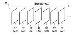
- a moving image 30 to be encoded is composed of a plurality of pictures (also referred to as picture images) 32 that are continuous in time series.
- the leftmost picture 32 is the first picture 32, that is, the first picture 32.
- the image data of each picture 32 corresponds to the image data 22 described above. Therefore, the image data 22 of each picture 32 is sequentially input to the encoding device 14.
- the picture 32 is a frame (also referred to as a frame image) in a non-interlace format (also referred to as a progressive format) is illustrated.
- the image data 22 is input to the encoding device 14 at, for example, a predetermined frame rate, in other words, at a predetermined time interval.
- a field also referred to as a field image
- a frame composed of two fields can be adopted as the picture 32.
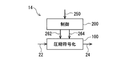
- FIG. 3 shows a block diagram outlining the encoding device 14.
- the encoding device 14 illustrated in FIG. 3 includes a compression encoding unit 100 and a control unit 200.
- compression encoding means and “control means” are abbreviated as “compression encoding” and “control”, respectively. This notation method is also used in the drawings described later.
- the compression encoding unit 100 acquires the original image data 22 as an input for each picture, and generates encoded data 24 by compressing and encoding the original image data 22 (generation processing). Then, the compression encoding unit 100 outputs the generated encoded data 24 to a wired or wireless transmission path (output process).
- the compression encoding is H.264.
- H.264 is exemplified.
- data generated by inter encoding hereinafter also referred to as inter encoded data
- intra encoded data data generated by intra encoding
- the intra-encoded data is data obtained by encoding the image data 22 of the picture 32 to be encoded regardless of the other pictures 32 (see FIG. 2). For this reason, intra-encoded data can be decoded by itself.
- Intra coded data is also referred to as an intra coded picture, an I picture, or the like.
- intra coding the picture 32 may be divided into a plurality of blocks (or macro blocks) and intra prediction using the correlation between the blocks may be performed.
- intra-encoded data refers to data encoded without depending on other pictures regardless of whether or not intra prediction is executed.
- Inter-encoded data is data obtained by encoding inter-prediction using inter-prediction using correlation with another picture 32 (or a predicted picture thereof). For this reason, inter-coded data cannot be decoded unless data of a picture (referred to as a reference picture or a reference screen) referred to at the time of inter prediction is used. Inter-coded data is also called an inter-coded picture. There are two types of inter-coded pictures: a P picture predicted based on a front picture and a B picture predicted based on a front picture and a rear picture. is there.
- the control unit 200 performs selection control as to which of the inter-encoded data and the intra-encoded data is output to the compression encoding unit 100. For example, the control unit 200 acquires a signal 250 related to an instruction or request for generating either inter-coded data or intra-coded data, and generates a control signal 262 corresponding to the content of the signal 250. Output to the compression encoding means 100. Thereby, the compression coding means 100 generates and outputs either inter-coded data or intra-coded data in accordance with the control signal 262.
- the signal 250 is a signal for requesting the generation of intra-encoded data
- the control signal 262 is a signal for causing the compression encoding unit 100 to generate intra-encoded data
- the control unit 200 obtains the intra encoded data generation request signal 250 and outputs the intra encoded data generation instruction signal 262 to the compression encoding unit 200.
- the signals 250 and 262 may be, for example, signals including information for distinguishing whether the generation request is intra-coded data or inter-coded data.
- control signal 250 is supplied from the outside of the control unit 200
- the control signal 250 may be a signal generated inside the control unit 200, as will be exemplified later. Absent.
- the control unit 200 also controls the compression encoding unit 100 on the amount of code generated by compression encoding (or the amount of code generated per unit time (so-called code generation rate)). For example, the control unit 200 generates the code amount control signal 264 by acquiring the intra encoded data request signal 250 and outputs the code amount control signal 264 to the compression encoding unit 100. Thereby, the compression encoding unit 100 sets the code amount according to the control signal 264.
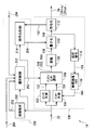
- FIG. 4 shows a block diagram outlining a more specific configuration example of the encoding device 14.
- H the present invention is not limited to the illustrated configuration example.
- the control unit 200 illustrated in FIG. 4 includes an image analysis unit 202, a selection control unit 212, and an encoding control unit 214.
- the intra prediction unit 102 receives the original image data 22 as input, generates intra prediction data (also referred to as an intra prediction picture) 152 by performing intra prediction on the image data 22, and outputs the prediction data 152. To do. Since intra prediction is a well-known method, detailed description thereof is omitted here.
- the inter prediction means 104 acquires the original image data 22 and data 164 (described later) stored in the reference image memory 116 as inputs. Then, the inter prediction unit 104 generates inter prediction data (also referred to as an inter prediction picture) 154 related to the input original image data 22 by performing inter prediction based on the data 22 and 164, and the prediction data 154 is output.
- inter prediction is a well-known method, the detailed description is abbreviate
- the intra / inter selection unit 106 receives the intra prediction data 152, the inter prediction data 154, and the control signal 262 output from the selection control unit 212 of the control unit 200 as inputs, and inputs both according to the selection instruction by the control signal 262. One of the prediction data 152 and 154 is selected, and the selected prediction data 156 is output.
- the conversion unit 108 acquires the prediction data 156 output from the intra / inter selection unit 106 as input, performs predetermined conversion on the prediction data 156, and outputs converted data 158.
- predetermined transformation so-called discrete cosine transformation (DCT) is exemplified.
- DCT discrete cosine transformation
- the prediction data 156 is orthogonally transformed into DCT coefficients 158 in the frequency domain.
- the quantization unit 110 acquires the DCT coefficient 158 and the control signal 264 output from the encoding control unit 214 of the control unit 200 as inputs.
- the quantization unit 110 converts the DCT coefficient 158 into the quantization coefficient 160 by performing quantization on the DCT coefficient 158 according to the content of the control signal 264, and outputs the obtained quantization coefficient 160.
- Such quantization is performed, for example, by dividing the DCT coefficient 158 by a quantization step and rounding the division result to an integer value. The quantization will be further described in the description of the encoding control unit 214.
- the encoding unit 112 obtains the quantized coefficient 160 as an input, generates encoded data 24 by performing predetermined encoding on the coefficient 160, and outputs the data 24.
- predetermined encoding for example, variable length encoding such as Huffman encoding or arithmetic encoding can be employed.
- the encoded data 24 may be output after the encoding of the entire picture is completed, or may be performed sequentially (for example, in units of slices) for one picture.
- the reference code “24tra” is used for the intra-coded data, and the reference code “24tra” is used for the inter-coded data, if necessary.
- the encoding unit 112 also outputs information 162 of the data amount of the generated encoded data 24 (in other words, the amount of generated code) to the encoding control unit 214 as appropriate.
- the local decoding unit 114 acquires the quantization coefficient 160 output from the quantization unit 110 as an input. Then, the local decoding unit 114 performs processing opposite to the quantization in the quantization unit 110 (referred to as inverse quantization) on the quantization coefficient 160 and the inverse of the discrete cosine transform in the conversion unit 108. Processing (called inverse discrete cosine transform, inverse DCT, etc.) is sequentially performed. Thereby, the reconstructed prediction data 164 is generated and output from the local decoding unit 114. Note that the local decoding unit 114 may perform, for example, intra compensation, motion compensation, or the like on the calculation result by inverse DCT.
- the reference image memory 116 is a means for storing the reconstructed prediction data 164 output from the local decoding means 114.
- the prediction data 164 stored in the memory 116 is used as a reference image when the inter prediction unit 104 performs inter prediction.
- the image analysis unit 202 acquires the original image data 22 as an input, detects a scene change (that is, a scene change) in the moving image 30 (see FIG. 2) based on the data 22, and outputs a signal 252 as a detection result. Output.
- the scene change can be detected, for example, by comparing the image data 22 of two consecutive pictures 32. More specifically, it is possible to determine that a scene change has occurred when a difference value, an average value, or the like between the image data 22 is larger than a predetermined threshold value. Conversely, when the difference value or the like is equal to or less than the threshold value, it can be determined that no scene change has occurred.
- the scene change detection signal 252 is an example of a signal 250 (see FIG. 3) that requests the compression encoding unit 100 to generate intra-encoded data 24tra.
- the request signal 250 may be generated inside the control unit 200, unlike the illustration of FIG.
- a moving image supply source controls the signal 254 for notifying the scene change together with the original image data 22.
- the moving image supply source can be configured to output, as the notification signal 254, information about whether or not the picture 32 hits the scene change position together with the drawing information of the picture 32.
- the scene change notification signal 254 can be transmitted.
- control unit 200 acquires both the signals 252 and 254, which are specific examples of the intra-encoded data request signal 250 (see FIG. 3).
- signals 252 and 254 which are specific examples of the intra-encoded data request signal 250 (see FIG. 3).
- a configuration in which only one of the signals 252 and 254 is acquired may be employed.
- the generation of the intra encoded data 24tra is required for error recovery even when a communication error occurs between the encoding device 14 and the decoding device 16 (see FIG. 1), for example.
- the request signal 256 transmitted from the decoding device 16 corresponds to an example of the intra encoded data request signal 250 given from the outside of the control means 200.
- the intra encoded data request signals 252, 254, and 256 are input to the selection control unit 212.
- the selection control means 212 can be configured using a register, for example. More specifically, for example, when the state “0” of the register is associated with a request for generation of intra-encoded data 24tra, and the state “1” of the register is requested to generate inter-encoded data 24ter To correspond to. In this case, the register is set to “0” by inputting at least one of the intra-encoded data request signals 252, 254, and 256. Thereafter, after the input of the image data 22 to be intra-encoded is confirmed, the register is set to “1”. The selection control unit 212 can output a control signal 262 for generating intra-coded data in accordance with the state of the register.
- the first picture 32 of the moving image 30 also needs to be converted into intra-coded data 24tra.
- the first picture 32 can be detected, for example, by detecting power-on of the encoding device 14.
- the register is configured to be reset to “0” when the encoding device 14 is turned on, thereby requesting intra coding for the image data 22 that is input first after the power is turned on. It is possible. After the input of the image data 22 of the first picture 32 is confirmed, the register is set to “1”.
- the power supplied when the power is turned on corresponds to an example of an intra-coded data request signal 250 generated inside the control unit 200.
- one register may be shared by the various aspects of the intra-encoded data request signal 250, or a register may be provided for each of the various aspects.
- the intra encoding instruction signal 262 output from the selection control unit 212 is input to the intra / inter selection unit 106 and the encoding control unit 214.
- the intra / inter selection means 106 outputs the intra prediction data 152 when the intra encoding instruction signal 262 is received, and outputs the inter prediction data 152 when the intra encoding instruction signal 262 is not received.
- the encoding control unit 214 outputs the control signal 264 related to the generation of the intra encoded data 24tra to the quantizing unit 110 in response to the reception of the intra encoding instruction signal 262. On the other hand, the encoding control unit 214 outputs a control signal 264 related to the generation of the inter encoded data 24ter to the quantizing unit 110 when the intra encoding instruction signal 262 is not received.
- control signal 264 includes information on quantization parameters having a predetermined relationship with the quantization step used in the quantization means 210. For this reason, the quantization means 110 derives a quantization step from the quantization parameter included in the control signal 264 according to the previously defined relationship, and performs quantization using the obtained quantization step.
- the encoding control unit 214 can control the quantization step via the quantization parameter included in the control signal 264.
- the encoding control unit 214 acquires the past code generation amount information 162 from the encoding unit 112. Can be set.
- a quantization parameter that is, a quantization step, irrespective of the past code generation amount.
- the quantization parameter has a proportional relationship with the quantization step.
- the quantization parameter is proportional to the logarithm of the quantization step.
- the quantization step increases as the quantization parameter increases.
- the quantization step is an index or index value indicating the roughness of the quantization (in other words, fineness). For this reason, the smaller the quantization step, in other words, the smaller the quantization parameter, the more the deterioration of the image quality is suppressed, but the code amount (in other words, the data amount) generated by the encoding means 112 increases. That is, the smaller the quantization step and the quantization parameter, the smaller the compression ratio.
- the encoding control unit 214 can control the amount of code generated by the compression encoding unit 100 by the control signal 264, more specifically by the quantization parameter included in the control signal 264. .
- code amount control will be described later.
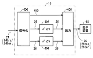
- FIG. 5 shows a block diagram outlining the decoding device 16.
- the display device 18 is also shown.
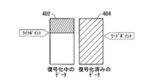
- the decoding device 16 illustrated in FIG. 5 includes a decoding unit 400, buffers 402 and 404, and a display device output unit 406.
- the decoding unit 400 acquires the encoded data 24 transmitted from the encoding device 14 (see FIG. 1) as an input. Then, the decoding unit 400 generates the decoded data 26 by decoding the acquired encoded data 24 according to a decoding method corresponding to the encoding method in the compression encoding unit 100 (see FIG. 4). The decrypted data 26 is output.
- the decoded data 26 obtained by decoding the intra-coded data 24tra is referred to as intra-decoded data 26tra
- the decoded data 26 obtained by decoding the inter-coded data 24ter is inter-decoded. This data will be referred to as converted data 26ter.
- the decoding unit 400 outputs the generated decoded data 26 (intra decoded data 26tra or inter decoded data 26ter) to one of the two buffers 402 and 404.
- the decoding unit 400 alternately uses the buffers 402 and 404 as storage destination buffers. For example, one buffer 402 is used for odd-numbered decoded data 26 and the other buffer 404 is used for even-numbered decoded data 26. According to such a double buffer configuration, it is possible to easily prevent the data 26 not read by the output means 406 from being overwritten and lost (see the schematic diagram of FIG. 6).
- the decoding unit 400 outputs a notification signal 450 indicating that to the output unit 406 along with the decoding of the intra encoded data 24tra. Note that the encoded data 24 is appended with information indicating whether the data 24 is intra-coded data 24tra or inter-coded data 24ter. Is possible.
- the notification signal 450 may adopt, for example, a signal form that is continued during the decoding of the intra-encoded data 24tra, or a signal form that is transmitted at the start and end of decoding. May be.
- the output means 406 is an interface that connects the decryption device 16 and the display device 18.
- the output means 406 basically selects the buffers 404 and 406 alternately, and reads the stored decoded data 26 (intra decoded data 26tra or inter decoded data 26ter) from the selected buffer.
- the output unit 406 repeatedly reads out the decoded data 26 from a buffer opposite to the buffer in which the intra decoded data 26tra is being stored until decoding of the intra encoded data 24tra is completed.
- the inter decoded data 26 corresponding to the inter encoded data 24ter received immediately before the intra encoded data 24tra being decoded is repeatedly read out.
- the output unit 406 can determine whether or not the intra-encoded data 24tra is being decoded based on the notification signal 450.
- the output unit 406 sequentially outputs the decoded data 26 sequentially read from the buffers 402 and 404 to the display device 18.
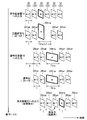
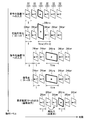
- FIG. 7 shows a schematic diagram outlining the operation of the system 12.
- the flow of the operation sequence is taken in the downward direction, and the passage of time is taken in the right direction.
- the original picture 32 to be processed and various data corresponding thereto are schematically illustrated by a figure in which a quadrangle is perspective.
- a quadrangle is perspective.
- the outline of the data amount of the picture 32 or the like is expressed by the area of the rectangle.
- the equal area among the three of the original image data 22, the encoded data 24, and the decoded data 26 does not necessarily mean that the data amount is the same.
- outlines of various time lengths related to the picture 32 and the like are expressed by the horizontal dimension of the rectangle.
- FIG. 7 shows an example of the processing status for the ⁇ m ⁇ 2 ⁇ th to ⁇ m + 3 ⁇ th input pictures 32, and the order is entered in the rectangle. That is, the characters in the rectangle are not images.
- intra coding or the like is performed on the mth picture 32 (shown in bold in the drawing for the sake of clarity), and inter coding or the like is performed on the remaining picture 32.
- m is an integer greater than or equal to 4, and it is assumed that the ⁇ m-2 ⁇ -th picture 32 is not the first (that is, the first) picture 32.
- the case where the mth picture 32 is the first picture can be easily understood from the following description.
- the image data 22 of the ⁇ m ⁇ 2 ⁇ th to ⁇ m + 3 ⁇ th pictures 32 is sent to the encoding device 14 in this order and every predetermined time T. Entered. That is, the image data 22 of the ⁇ m-2 ⁇ -th picture 32 is input within the first time T in the illustrated range of FIG. 7, and the image data of the ⁇ m-1 ⁇ -th picture 32 within the subsequent time T. 22) is input, and thereafter the image data 22 is sequentially input in the same manner.
- the predetermined time T is a time assigned in advance to one picture 32, and corresponds to one frame period here. For example, when the frame rate is 30 frames / second, the length of the time T is 1/30 seconds.
- the encoding device 14 performs compression encoding on each of the input image data 22 to generate encoded data 24.
- FIG. 7 illustrates a case where compression encoding is started without delay with respect to the input of the image data 22, it is not limited to such an example.
- each image data 22 is sequentially input at the intervals of the time T, the time per picture allowed for the processing (including generation and output of the encoded data 24) by the compression encoding means 100 is included. Is basically the time T.
- the encoding control means 214 (see FIG. 4) performs the following code amount control.
- the encoding control unit 214 depends on the transmission rate of the wired or wireless transmission path for transmitting the encoded data 24 to the decoding device 16.
- a code amount equal to or less than the maximum code amount (calculated by multiplying the upper limit transmission rate of the transmission path and the allowable time T) is set.
- the encoding control unit 214 is larger than the maximum code amount and N times the maximum code amount (N is an integer of 2 or more). The following code amount is set.
- the value of N is set in advance.
- the difference in the code amount (data amount) between the inter-coded data 24ter and the intra-coded data 24tra is expressed by the difference in the area of the quadrangle representing these data 24ter and 24tra. ing. Although all of the inter-coded data 24ter is illustrated with the same area, this is merely a simplified illustration to avoid complication of the drawing.
- the horizontal dimension of the rectangle representing the encoded data 24 represents an outline of the generation time of the encoded data 24.
- the output of the inter-coded data 24ter can be completed within the allowable time T per picture.
- the intra-coded data 24tra that has been increased from the maximum code amount cannot be output within the allowable time T due to the limitation of the transmission rate. For this reason, a processing time Ttra that is N times the allowable time T is assigned to the generation / output of the intra-coded data 24tra.
- the generation of the intra encoded data 24tra itself can be completed within the allowable time T, but the output of the generated encoded data 24tra is subjected to the transmission rate limitation.
- ⁇ T ⁇ 2 ⁇ processing time is required for the entire processing related to the intra-coded data 24tra.
- the image data 22 of the next ⁇ m + 1 ⁇ th picture 32 is supplied to the compression coding means 100 while the intra encoded data 24tra corresponding to the mth picture 32 is being output to the transmission path.
- the compression encoding means 100 does not generate and output the encoded data 24 for the ⁇ m + 1 ⁇ th input image data 22, but encodes the next ⁇ m + 2 ⁇ th input image data 22.
- the generation and output of data 24 is resumed. That is, the ⁇ m + 1 ⁇ th input image data 22 is thinned out for generation and output of the encoded data 24.
- the generation and output of the encoded data 24 are not performed for ⁇ N ⁇ 1 ⁇ pictures 32 following the picture 32 corresponding to the intra encoded data 24tra, and the next of the ⁇ N ⁇ 1 ⁇ pictures 32.
- the picture 32 is resumed.
- the intra / inter selection means 106 obtains the value of N in advance and counts the number ⁇ N-1 ⁇ to be thinned out. This can be realized by not outputting any inter prediction data 154.
- the encoding unit 112 may perform the output limitation and the cancellation of the intra / inter selection unit 106.
- the encoding unit 112, the control unit 200, or the like may perform data input restriction on the encoding unit 112 or the compression encoding unit 100 and release it.
- the encoded data 24 sequentially transmitted from the encoding device 14 is sequentially received by the decoding device 16. 7, the encoded data 24 received by the decoding device 16 corresponds to the ⁇ m + 1 ⁇ -th picture 32 thinned out by the encoding device 14. Inter-coded data 24ter is not included.
- the square area representing the encoded data 24 represents the outline of the code amount (data amount) as in the second level.
- the horizontal dimension of the square representing the encoded data 24 represents the outline of the reception time of the encoded data 24.
- the encoded data 24ter and 24tra are respectively stored at predetermined times T and Ttra as shown in the third row of FIG.
- the reception can be completed within.
- reception of the increased amount of intra-encoded data 24tra takes a time Ttra longer than the allowable time T as a result of the limitation of the transmission rate of the transmission path.
- FIG. 7 illustrates a delay time D from the start of compression encoding (here, when the image data 22 is input to the encoding device 14) until the encoded data 24 reaches the decoding device 16. is doing.
- the delay time D includes a processing time spent for generating and outputting the encoded data 24 and a transmission time spent for transmission between the devices 14 and 16.
- the decoding device 16 decodes the input encoded data 24 to generate decoded data 26.
- FIG. 7 illustrates a case where decoding is started without delay with respect to the input of the encoded data 24, it is not limited to such an example.
- the area of the square representing the encoded data 24 represents the outline of the code amount (data amount) as in the second level and the third level.
- the horizontal dimension of the rectangle representing the encoded data 24 represents an outline of the processing time required for decoding the encoded data 24.
- the decoding of the encoded data 24ter and 24tra can be completed within a predetermined time T and Ttra, respectively.
- the reception itself takes longer than the allowable time T, so that decoding also takes longer than the allowable time T.
- the decoding device 16 sequentially outputs the decoded data 26 to the display device 18 as described above. Thereby, the image based on each decoding data 26 is continuously displayed on the display device 18, and the decoded moving image is obtained.
- FIG. 7 illustrates a case where there is a delay of the same length as the processing time T from the start of decoding until the decoded data 26 is output, but is not limited to this example. .
- the decoding processing time Ttra of the intra encoded data 24tra is longer than the decoding processing time T of the inter encoded data 24ter. For this reason, after the output of the inter decoded data 26ter corresponding to the ⁇ m ⁇ 1 ⁇ th picture 32, the decoding of the intra decoded data 26ter corresponding to the mth picture 32 has not been completed. sell.
- the output unit 406 of the decoding device 16 has the inter decoded data 26ter immediately before the intra decoded data 26tra, that is, the ⁇ m ⁇ 1 ⁇ th, as shown in the bottom of FIG.
- the decoded data 26ter corresponding to the picture 32 is output again.
- the decoded data 26ter corresponding to the ⁇ m ⁇ 1 ⁇ th picture 32 is displayed again.
- the inter decoded data 26ter corresponding to the inter encoded data 24ter received immediately before the intra encoded data 24tra is repeatedly output to the display device 18 until the decoding of the intra encoded data 24tra is completed.
- the repeated display of the same decoded data 26ter is preferably limited to the time when it is not recognized as a still image by human eyes. This is because if the same image (pattern) continues beyond a predetermined time, it is likely to be recognized as a still image by human eyes, and as a result, the image quality as a moving image may be deteriorated.
- the predetermined time is approximately 0.1 seconds, although there are individual differences. In other words, for example, when the frame rate of the input moving image is 30 frames / second, it is preferable to select 2 or 3 as the value of N (N is an integer of 2 or more).
- the decoding device 16 According to the encoding device 14, the decoding device 16, the system 12, and the various techniques employed in these, the following effects can be obtained.
- the code amount of the intra-coded data 24tra is set to be larger than the maximum code amount specified based on the transmission rate of the transmission path. For this reason, the picture quality of the picture obtained by decoding the intra-coded data is improved as compared with the case where the code quantity of the intra-coded data 24tra is set to be equal to or less than the maximum code quantity as with the inter-coded data 24ter. Can be made. Furthermore, as a result, the image quality of the entire decoded moving image can be improved.
- the maximum code amount that is generated for both inter-coded data and intra-coded data is determined according to the transmission rate.
- the quantization parameter was controlled to be as follows.
- the encoding device 14 allows a code amount exceeding the maximum code amount for intra-encoded data.
- the output is limited by the transmission rate, it takes more time to complete the output to the transmission path than the inter-coded data.
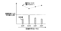
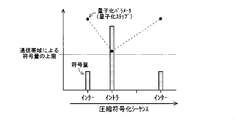
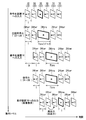
- FIGS. 8 and 9 illustrate a case where the amount of inter-coding is fluctuating.
- the amount of generated code depends on the design (content of the image), so it is very difficult to make the amount of code constant. Therefore, the example illustrated here is an example of the result of encoding with the aim of high image quality as much as possible below the upper limit of the code amount by the communication band, that is, a high code amount.
- the second stage of FIG. 7 illustrates an aspect in which the generation of the intra encoded data 24tra itself can be completed within the allowable time T as described above.
- the second row of FIG. 10 it is also possible to perform inter coding on the ⁇ m + 1 ⁇ th picture 32 that has been thinned out in the above.
- output delay and delay accumulation occur as described above.
- the encoded data 24 that is not scheduled to be output to the transmission path is not even generated as shown in the example of FIG. 7 in order to reduce the processing amount. Note that, as a result of the reduction in processing amount, it is possible to save power.
- the compression encoding means 100 has the performance that the intra encoded data 24tra itself can be completed within the allowable time T as described above, it takes a long time Ttra to complete the output due to the transmission rate. If there is, the generation time of the intra encoded data 24tra may be longer than the allowable time T (see FIG. 11).
- the processing related to the intra-coded data 24tra may be performed over the entire processing time Ttra that is longer than the allowable time T and not longer than N times the allowable time T.
- the intra encoded data 24tra can be generated with a code amount exceeding the maximum code amount, and the increased intra encoded data 24tra can be transmitted while limiting the transmission rate. Output can be completed.
- the processing load of the compression encoding means 100 can be reduced as compared with the example of FIG. Further, since the necessity of adopting a high-performance configuration for the compression encoding unit 100 is reduced as the processing load is reduced, cost reduction, power saving, and the like can be achieved.
- the intra-encoded data 24tra requires a longer decoding time than the inter-encoded data 24ter. However, until the decoding of the intra-encoded data 24tra is completed, the immediately preceding inter-encoded data 24ter is changed. The decoded image is repeatedly displayed. For this reason, it is possible to prevent an image loss (for example, an image of a full black display is interrupted) in the decoded moving image.
- the quality of a moving image can be improved by preventing image loss and further preventing display defects caused by the image loss (for example, the image flickers due to the presence of the image loss).
- the compression encoding unit 100 performs predetermined processing (including generation and output to the transmission path) on the intra-encoded data 24tra longer than the allowable time T and N times the allowable time T. It is sufficient to take a processing time less than this time.
- the code amount of the intra-coded data 24tra can be made larger than the maximum code amount that can be generated / output within the allowable time T per picture. For this reason, it is possible to improve the picture quality of a picture obtained by decoding the intra-encoded data 24tra as compared with the case where only the allowable time T is allocated to the intra-encoded data 24tra. Furthermore, as a result, the image quality of the entire decoded moving image can be improved.
- the processing load on the compression encoding means 100 can be reduced as compared with the case where the increased amount of intra encoded data 24tra is generated within the allowable time T. For this reason, the necessity for adopting a high-performance configuration for the compression encoding means 100 is reduced, and a configuration with a low processing speed can be employed. As a result, cost reduction and power saving can be achieved.
- the image immediately after the scene change is encoded as an I picture and set at the beginning of a new GOP (Group Of Picture).
- the picture type (type of I, P, B picture) is determined based on the detection result of the scene change and the accumulated data of the result of encoding in the past, and the determined picture type
- the encoding bit rate is controlled according to the above.
- a method of changing the GOP length and a method of fixing the GOP length and allocating the information amount of each picture at the fixed length are introduced.
- Patent Document 1 does not disclose the above-described various methods employed in the encoding device 14 or the like. For example, a method for increasing the code amount of the intra-coded data 24tra while satisfying the restriction caused by the transmission rate of the transmission path and the restriction caused by the performance of the compression coding means 100 to improve the image quality is as follows. This is not disclosed in Patent Document 1. Further, for example, Patent Document 1 does not disclose a method of thinning out image data 22 input during execution of intra coding. Also, Patent Document 1 does not disclose a method for repeatedly outputting inter decoded data 26ter immediately before the intra decoded data 26tra to the display device.
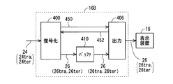
- FIG. 12 shows a block diagram outlining the decoding device 16B adopting a single buffer configuration.
- the decoding device 16B has a configuration in which the two buffers 404 and 406 are changed to one buffer 410 in the decoding device 16 (see FIG. 5).
- both intra decoded data 26tra and inter decoded data 26ter are stored in the buffer 410.
- the output means 406 instructs the write permission / prohibition with respect to the decryption means 400 with the signal 452 to prevent the necessary data 26 from being overwritten and lost.
- the storage area of the decoded data 26 that has been output to the display device 18 can be overwritten.
- the generation of such an overwrite-permitted area or the designation of the position of the area is notified to the decoding means 400 by a write permission signal 452.
- the decoding unit 400 Upon receiving the signal 452, the decoding unit 400 performs decoding and writes the decoded data 26 in the permissible area (see the schematic diagram in FIG. 13).
- the write permission signal 452 may be transmitted when a storage area having a size capable of storing the entire decoded data 26 is generated, or the decoded data 26 may be partially (for example, in block units). It may be transmitted when a storage area of a size that can be stored is generated.
- ⁇ Modification 2> a case where both the intra prediction data 152 and the inter prediction data 154 are generated for the same input image data 22 is illustrated (see FIG. 4).
- the control unit 200 controls only one of the intra prediction unit 102 and the inter prediction unit 104 in accordance with reception / non-reception of the intra encoding request signal 250 (see FIG. 3), so that intra prediction is performed. It is also possible to modify to generate only one of the data 152 and the inter prediction data 154. In such a case, the various effects described above can be obtained.
- intra coding is a process of coding a target picture 32 without depending on other pictures 32.
- intra coding includes a case where the input image data 22 is coded as it is without performing intra prediction.
- FIG. 14 illustrates a block diagram of the encoding device 14B in view of this point.
- the intra prediction unit 102 is removed from the configuration illustrated in FIG. 4, the input image data 22 is input to the intra / inter selection unit 106, and the input image data 22 and the inter prediction from the intra / inter selection unit 106 are input. Either data 154 or one of them is output.
- Other configurations of the encoding device 14B are the same as those of the encoding device 14 (see FIG. 4). The various effects described above can also be obtained by the encoding device 14B.
Landscapes
- Engineering & Computer Science (AREA)
- Multimedia (AREA)
- Signal Processing (AREA)
- Compression Or Coding Systems Of Tv Signals (AREA)
Abstract
L'invention porte sur un dispositif et similaires qui sont capables de supprimer une détérioration de qualité d'image provoquée par un codage d'une image animée. Un moyen de codage par compression (100) génère des données inter-codées (24ter) ou des données intra-codées (24tra) par codage par compression de données d'image (22) portant sur chacune des images composant une image animée d'entrée, et émet les données codées (24ter, 24tra) à un trajet de transmission câblé ou sans fil. Lorsque l'on amène le moyen de codage par compression (100) à générer les données inter-codées (24ter), un moyen de commande (200) configure la quantité de code inférieure ou égale à une quantité de code maximale donnée par la valeur de multiplication du débit de transmission maximal du trajet de transmission et du temps alloué autorisé à une image sur la base de la fréquence d'image de l'image animée d'entrée. Lorsque l'on amène le moyen de codage par compression (100) à générer les données intra-codées (24tra), le moyen de commande (200) configure la quantité de code afin qu'elle soit plus grande que la quantité de code maximale et plus petite ou égale à N fois (N étant un entier supérieur ou égal à 2) la quantité de code maximale.
Priority Applications (1)
| Application Number | Priority Date | Filing Date | Title |
|---|---|---|---|
| US13/520,306 US20120307881A1 (en) | 2010-03-03 | 2010-11-09 | Image coding device, image coding/decoding system, image coding method, and image display method |
Applications Claiming Priority (2)
| Application Number | Priority Date | Filing Date | Title |
|---|---|---|---|
| JP2010046223A JP5694674B2 (ja) | 2010-03-03 | 2010-03-03 | 画像符号化装置、画像符号化復号化システム、画像符号化方法、画像表示方法 |
| JP2010-046223 | 2010-03-03 |
Publications (1)
| Publication Number | Publication Date |
|---|---|
| WO2011108146A1 true WO2011108146A1 (fr) | 2011-09-09 |
Family
ID=44541822
Family Applications (1)
| Application Number | Title | Priority Date | Filing Date |
|---|---|---|---|
| PCT/JP2010/069939 WO2011108146A1 (fr) | 2010-03-03 | 2010-11-09 | Dispositif de codage d'image, système de codage/décodage d'image, procédé de codage d'image, et procédé d'affichage d'image |
Country Status (3)
| Country | Link |
|---|---|
| US (1) | US20120307881A1 (fr) |
| JP (1) | JP5694674B2 (fr) |
| WO (1) | WO2011108146A1 (fr) |
Cited By (1)
| Publication number | Priority date | Publication date | Assignee | Title |
|---|---|---|---|---|
| CN103618903A (zh) * | 2013-12-10 | 2014-03-05 | 天津大学 | 高速低功耗无线传感网络视频压缩采样方法及装置 |
Families Citing this family (3)
| Publication number | Priority date | Publication date | Assignee | Title |
|---|---|---|---|---|
| JP2014017554A (ja) * | 2012-07-05 | 2014-01-30 | Canon Inc | 画像符号化装置 |
| CN107534780A (zh) * | 2015-02-25 | 2018-01-02 | 瑞典爱立信有限公司 | 视频中的帧间画面的编码和解码 |
| JP7210944B2 (ja) * | 2018-09-05 | 2023-01-24 | 富士通株式会社 | 映像符号化装置、映像符号化方法および映像符号化プログラム |
Citations (3)
| Publication number | Priority date | Publication date | Assignee | Title |
|---|---|---|---|---|
| JPH07203458A (ja) * | 1993-12-27 | 1995-08-04 | Olympus Optical Co Ltd | 動画像符号化装置 |
| JP2006287864A (ja) * | 2005-04-05 | 2006-10-19 | Nippon Hoso Kyokai <Nhk> | 符号化装置および符号化プログラム |
| JP2009290712A (ja) * | 2008-05-30 | 2009-12-10 | Mega Chips Corp | トランスコーダ |
Family Cites Families (16)
| Publication number | Priority date | Publication date | Assignee | Title |
|---|---|---|---|---|
| JP2871316B2 (ja) * | 1992-07-10 | 1999-03-17 | 日本ビクター株式会社 | 動画像符号化装置 |
| US6058459A (en) * | 1996-08-26 | 2000-05-02 | Stmicroelectronics, Inc. | Video/audio decompression/compression device including an arbiter and method for accessing a shared memory |
| US20020154694A1 (en) * | 1997-03-21 | 2002-10-24 | Christopher H. Birch | Bit stream splicer with variable-rate output |
| JP3551887B2 (ja) * | 2000-04-03 | 2004-08-11 | 日本電気株式会社 | 動画像再生方法および装置 |
| JP2002125226A (ja) * | 2000-10-17 | 2002-04-26 | Matsushita Electric Ind Co Ltd | フレームレート制御方法及び画像伝送装置 |
| US20020087976A1 (en) * | 2000-12-28 | 2002-07-04 | Kaplan Marc P. | System and method for distributing video with targeted advertising using switched communication networks |
| US7034890B2 (en) * | 2001-04-13 | 2006-04-25 | Ati Technologies, Inc. | Method and apparatus for updating a computer system clock from a real time television signal |
| US20030204630A1 (en) * | 2002-04-29 | 2003-10-30 | The Boeing Company | Bandwidth-efficient and secure method to combine multiple live events to multiple exhibitors |
| US7418037B1 (en) * | 2002-07-15 | 2008-08-26 | Apple Inc. | Method of performing rate control for a compression system |
| JP4118232B2 (ja) * | 2003-12-19 | 2008-07-16 | 三菱電機株式会社 | 映像データ処理方法および映像データ処理装置 |
| KR100619041B1 (ko) * | 2004-07-22 | 2006-09-01 | 삼성전자주식회사 | 비디오 동기화 장치 및 비디오 동기화 방법 |
| WO2007110561A1 (fr) * | 2006-03-27 | 2007-10-04 | Nds Limited | Système de substitution vidéo |
| US7684332B2 (en) * | 2006-08-22 | 2010-03-23 | Embarq Holdings Company, Llc | System and method for adjusting the window size of a TCP packet through network elements |
| US7456760B2 (en) * | 2006-09-11 | 2008-11-25 | Apple Inc. | Complexity-aware encoding |
| CN101647278B (zh) * | 2006-12-12 | 2012-05-30 | 梵提克斯公司 | 用于视频编码标准的改进的视频速率控制 |
| US8259814B2 (en) * | 2008-11-12 | 2012-09-04 | Cisco Technology, Inc. | Processing of a video program having plural processed representations of a single video signal for reconstruction and output |
-
2010
- 2010-03-03 JP JP2010046223A patent/JP5694674B2/ja not_active Expired - Fee Related
- 2010-11-09 WO PCT/JP2010/069939 patent/WO2011108146A1/fr active Application Filing
- 2010-11-09 US US13/520,306 patent/US20120307881A1/en not_active Abandoned
Patent Citations (3)
| Publication number | Priority date | Publication date | Assignee | Title |
|---|---|---|---|---|
| JPH07203458A (ja) * | 1993-12-27 | 1995-08-04 | Olympus Optical Co Ltd | 動画像符号化装置 |
| JP2006287864A (ja) * | 2005-04-05 | 2006-10-19 | Nippon Hoso Kyokai <Nhk> | 符号化装置および符号化プログラム |
| JP2009290712A (ja) * | 2008-05-30 | 2009-12-10 | Mega Chips Corp | トランスコーダ |
Cited By (2)
| Publication number | Priority date | Publication date | Assignee | Title |
|---|---|---|---|---|
| CN103618903A (zh) * | 2013-12-10 | 2014-03-05 | 天津大学 | 高速低功耗无线传感网络视频压缩采样方法及装置 |
| CN103618903B (zh) * | 2013-12-10 | 2017-01-04 | 天津大学 | 高速低功耗无线传感网络视频压缩采样方法 |
Also Published As
| Publication number | Publication date |
|---|---|
| JP2011182284A (ja) | 2011-09-15 |
| JP5694674B2 (ja) | 2015-04-01 |
| US20120307881A1 (en) | 2012-12-06 |
Similar Documents
| Publication | Publication Date | Title |
|---|---|---|
| JP5174958B2 (ja) | ビデオのコーダとデコーダとの同時最適化のための方法およびシステム | |
| US20070199011A1 (en) | System and method for high quality AVC encoding | |
| US20030095603A1 (en) | Reduced-complexity video decoding using larger pixel-grid motion compensation | |
| US20010046263A1 (en) | Video encoding apparatus that adjusts code amount by skipping encoding of image data | |
| US9392278B2 (en) | Image encoding or decoding apparatus, system, method, and storage medium for encoding or decoding a plurality of images in parallel | |
| WO2010106670A1 (fr) | Appareil de codage d'image, procédé de commande de codage d'image et programme de codage d'image | |
| US8170375B2 (en) | Image processing apparatus and method for controlling the same | |
| CN101960858A (zh) | 运动图像编码装置、摄像装置以及运动图像编码方法 | |
| KR20140143328A (ko) | 디지털 비디오 데이터를 인코딩하는 방법 | |
| JP2015171114A (ja) | 動画像符号化装置 | |
| US9386310B2 (en) | Image reproducing method, image reproducing device, image reproducing program, imaging system, and reproducing system | |
| JP2007507128A (ja) | 参照ピクチャのリフレッシュを遅延させて行うビデオ画像の符号化および復号化 | |
| WO2011108146A1 (fr) | Dispositif de codage d'image, système de codage/décodage d'image, procédé de codage d'image, et procédé d'affichage d'image | |
| US20070014364A1 (en) | Video coding method for performing rate control through frame dropping and frame composition, video encoder and transcoder using the same | |
| JP2003348597A (ja) | 画像符号化装置および画像符号化方法 | |
| WO2010100991A1 (fr) | Appareil de décodage d'un flux de données de film, procédé permettant de le commander, programme et support d'enregistrement | |
| JP2002199392A (ja) | 映像符号化方法および装置 | |
| US20110051815A1 (en) | Method and apparatus for encoding data and method and apparatus for decoding data | |
| JP4911625B2 (ja) | 画像処理装置、およびそれを搭載した撮像装置 | |
| KR101678138B1 (ko) | 동화상 부호화 방법, 장치 및 프로그램 | |
| JP6182888B2 (ja) | 画像符号化装置 | |
| JP4700992B2 (ja) | 画像処理装置 | |
| JP6874844B2 (ja) | 動画像符号化装置、動画像符号化方法、及び、動画像符号化プログラム | |
| WO2013073422A1 (fr) | Dispositif de codage vidéo | |
| JP2009118096A (ja) | 画像符号化装置及びその制御方法、コンピュータプログラム |
Legal Events
| Date | Code | Title | Description |
|---|---|---|---|
| 121 | Ep: the epo has been informed by wipo that ep was designated in this application |
Ref document number: 10847043 Country of ref document: EP Kind code of ref document: A1 |
|
| WWE | Wipo information: entry into national phase |
Ref document number: 13520306 Country of ref document: US |
|
| NENP | Non-entry into the national phase |
Ref country code: DE |
|
| 122 | Ep: pct application non-entry in european phase |
Ref document number: 10847043 Country of ref document: EP Kind code of ref document: A1 |