WO2011108049A1 - プラズマ生成装置 - Google Patents
プラズマ生成装置 Download PDFInfo
- Publication number
- WO2011108049A1 WO2011108049A1 PCT/JP2010/007214 JP2010007214W WO2011108049A1 WO 2011108049 A1 WO2011108049 A1 WO 2011108049A1 JP 2010007214 W JP2010007214 W JP 2010007214W WO 2011108049 A1 WO2011108049 A1 WO 2011108049A1
- Authority
- WO
- WIPO (PCT)
- Prior art keywords
- gas
- plasma generation
- plasma
- generation chamber
- conductor
- Prior art date
- Legal status (The legal status is an assumption and is not a legal conclusion. Google has not performed a legal analysis and makes no representation as to the accuracy of the status listed.)
- Ceased
Links
Images




Classifications
-
- H—ELECTRICITY
- H01—ELECTRIC ELEMENTS
- H01J—ELECTRIC DISCHARGE TUBES OR DISCHARGE LAMPS
- H01J37/00—Discharge tubes with provision for introducing objects or material to be exposed to the discharge, e.g. for the purpose of examination or processing thereof
- H01J37/32—Gas-filled discharge tubes
- H01J37/32009—Arrangements for generation of plasma specially adapted for examination or treatment of objects, e.g. plasma sources
- H01J37/32082—Radio frequency generated discharge
- H01J37/321—Radio frequency generated discharge the radio frequency energy being inductively coupled to the plasma
-
- H—ELECTRICITY
- H01—ELECTRIC ELEMENTS
- H01J—ELECTRIC DISCHARGE TUBES OR DISCHARGE LAMPS
- H01J37/00—Discharge tubes with provision for introducing objects or material to be exposed to the discharge, e.g. for the purpose of examination or processing thereof
- H01J37/32—Gas-filled discharge tubes
- H01J37/32431—Constructional details of the reactor
- H01J37/3244—Gas supply means
Definitions
- the present invention relates to a plasma generation apparatus for forming, for example, a thin film transistor (TFT) constituting a liquid crystal display device.
- TFT thin film transistor
- a crystalline thin film such as a silicon thin film is formed on a substrate. Yes.
- inductively coupled plasma is generated using high-frequency power from the viewpoint of obtaining a plasma that is as dense and uniform as possible in the plasma generation chamber.
- the method is known.
- a high frequency antenna is provided for the plasma generation chamber, and the high frequency antenna is used for the gas introduced into the room. By applying high frequency power, inductively coupled plasma is generated.
- the high frequency antenna is arranged inside the plasma generation chamber from the viewpoint of improving the utilization efficiency of the high frequency power supplied.
- the high-frequency antenna disposed inside the plasma generation chamber is formed of a conductor (conductive tube) made of a conductive material such as aluminum and an insulating material such as quartz. It is comprised by the insulator (insulating tube) provided so that it might coat
- the gas introducing chamber is provided on the wall of the plasma generating container formed inside and spaced apart from the high frequency antenna.
- a high frequency power is applied to the film forming gas introduced into the room by a tube by a high frequency antenna to generate inductively coupled plasma (see, for example, Patent Document 1).
- the conductor is covered with the insulator, the conductor is cooled to a low temperature by supplying cooling water into the conductor, and the conductor shape is curved. Because of the presence of the part, it may be difficult to separate the conductor from the plasma. Once the foreign matter adheres to the conductor, it is covered with an insulator, so even if cleaning with a cleaning gas is performed, the cleaning gas does not reach the conductor, and the foreign matter attached to the conductor There was a problem that it was difficult to remove.
- the present invention has been made in view of the above-described problems, and even when a high frequency antenna is formed by covering a conductor with an insulator, foreign matters attached to the conductor can be removed.
- An object is to provide a plasma generation apparatus.
- a plasma generation apparatus of the present invention includes a plasma generation container having a plasma generation chamber formed therein, a holder provided in the plasma generation chamber and holding a deposition target substrate, a plasma Conductor in a state where a gap is formed between the gas introduction tube provided in the generation vessel and introducing the film forming gas and the cleaning gas into the plasma generation chamber and the plasma generation chamber.
- a high-frequency antenna that generates high-frequency power by applying high-frequency power to the film-forming gas, and a cleaning gas introduced from the gas-introducing pipe is connected to the gas-introducing pipe inside the plasma generation chamber.
- a gas supply plate that supplies the gap.
- the cleaning gas is introduced by a gas introduction pipe for introducing a film forming gas during film formation, and the gas introduction pipe for introducing the film forming gas is also used as a means for introducing the cleaning gas. Therefore, the cleaning gas can be supplied with a simple configuration without separately providing another gas introduction pipe, and the cost can be reduced.
- a gas supply port for supplying a cleaning gas adjacent to the conductor may be formed in the gas supply plate.
- the gas supply port is formed adjacent to the conductor, the cleaning gas can be reliably supplied to the surface of the conductor. Therefore, it is possible to effectively remove the foreign matter adhering to the conductor.
- the plasma generation apparatus of the present invention may have a configuration in which a plurality of gas supply ports are provided.
- the insulator may be provided with a gas discharge port for discharging the cleaning gas toward the inside of the plasma generation chamber.
- the cleaning gas supplied to the inside of the high frequency antenna is passed through the gas discharge port formed in the insulator.
- the gas discharge port formed in the insulator it can be supplied into the plasma generation chamber. Therefore, even when a configuration in which a gas supply port is provided and cleaning gas is supplied to the inside of the high-frequency antenna is adopted, when the plasma generation chamber is cleaned, foreign matter present inside the plasma generation chamber is It becomes possible to prevent effectively adhering to the surface.
- the gas introduction pipe may be arranged between the terminals of the high frequency antenna, and the high frequency antenna and the gas introduction pipe may be integrated as a unit.
- the high-frequency antenna and the gas introduction pipe can be integrated as a unit, and it is not necessary to provide an installation area for providing the gas introduction pipe away from the high-frequency antenna in the wall portion of the plasma generation container. . Accordingly, the distance between the high-frequency antenna and the side wall of the plasma generation container can be reduced, so that the plasma generation container can be reduced in size. In particular, it is possible to reduce the size of a plasma generation apparatus for a large substrate.
- the plasma generation apparatus of the present invention may have a configuration in which a plurality of units are provided.
- the cleaning gas may be at least one selected from the group consisting of argon gas, helium gas, neon gas, krypton gas, and xenon gas.
- the conductor can be cleaned with a rare gas having chemically stable characteristics.
- the plasma generation apparatus of the present invention has an excellent characteristic that foreign matter adhering to a conductor can be removed even when the conductor is covered with an insulator to form a high-frequency antenna. . Therefore, the present invention is suitably used in a plasma generating apparatus in which the film forming gas is a silane-based gas, and with such a structure, plasma for forming a silicon thin film used for a solar cell or the like on a film forming substrate.
- the generation device can be reduced in size.
- FIG. 1 It is the schematic which shows the whole structure of the plasma production apparatus which concerns on embodiment of this invention. It is a figure for demonstrating the antenna unit in the plasma generator which concerns on embodiment of this invention, and is an enlarged view of the A section of FIG. It is a figure which shows the antenna and gas introduction pipe which comprise the antenna unit of the plasma generator which concerns on embodiment of this invention, and is an enlarged view of the B section of FIG. It is a top view which shows the state which arranged the multiple antenna unit in the plasma generator which concerns on embodiment of this invention. It is a top view which shows the state which arranged the multiple antenna unit in the plasma generator which concerns on embodiment of this invention.
- FIG. 1 is a schematic diagram illustrating an overall configuration of a plasma generation apparatus according to an embodiment of the present invention
- FIG. 2 is a diagram for explaining an antenna unit in the plasma generation apparatus according to an embodiment of the present invention. It is an enlarged view of the A section of FIG.
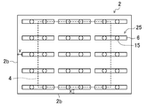
- FIG. 3 is a view showing an antenna and a gas introduction pipe constituting the antenna unit of the plasma generating apparatus according to the embodiment of the present invention, and is an enlarged view of a portion B in FIG. 4 and 5 are top views showing a state in which a plurality of antenna units are arranged in the plasma generating apparatus according to the embodiment of the present invention.
- FIG. 3 is a view showing an antenna and a gas introduction pipe constituting the antenna unit of the plasma generating apparatus according to the embodiment of the present invention
- FIG. 4 and 5 are top views showing a state in which a plurality of antenna units are arranged in the plasma generating apparatus according to the embodiment of the present invention.
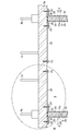
- FIG. 6 is a view for explaining a gas supply port for supplying a cleaning gas to the antenna constituting the antenna unit of the plasma generating apparatus according to the embodiment of the present invention, and is an enlarged view of a portion C in FIG. is there.
- FIG. 7 is a plan view for explaining a gas supply plate in which a gas supply port for supplying a cleaning gas to the antenna constituting the antenna unit of the plasma generating apparatus according to the embodiment of the present invention is formed.
- the plasma generation apparatus 1 includes a plasma generation container 2 in which a plasma generation chamber (film formation chamber) 3 is formed.
- the plasma generation container 2 is made of, for example, a metal such as aluminum or SUS.
- a holder 5 which is a holding member for holding the deposition target substrate 4 is installed in the lower part of the plasma generation chamber 3.
- a holder 5 for example, a flat plate holder whose surface is covered with alumina can be used.
- the holder 5 may be configured to incorporate a heater (not shown) for heating the deposition target substrate 4.
- two high frequency antennas 6 are inserted from the ceiling wall 2 a of the plasma generation container 2 into the plasma generation chamber 3.
- the high-frequency antenna 6 is used to generate plasma by applying high-frequency power to the deposition gas supplied into the plasma generation chamber 3, and is provided to face the holder 5 in the plasma generation chamber 3. ing.
- the two high-frequency antennas 6 have the same size, and are arranged next to each other in series with a predetermined interval on the same plane.
- the high-frequency antenna 6 has a substantially U-shaped cross section.
- a conductive material such as aluminum or copper is formed inside the plasma generation chamber 3.
- the conductor (conductive tube) 10 is formed of an insulating material such as quartz and is provided so as to cover the conductor 10 with a gap S formed between the conductor 10 and the conductor 10.
- An insulator (insulating tube) 11 is used.
- the conductor 10 constituting the high-frequency antenna 6 is a tubular body having a circular cross section.
- the shape of the conductor 10 is not limited to this, and for example, a rod having a circular cross section. It may be the body.
- the high frequency antenna 6 is insulated from the plasma generation container 2 by an insulating material, and is attached to the plasma generation container 2 by a fixing member (not shown) such as a bolt. .
- portions of the conductor 10 constituting the high-frequency antenna 6 that protrude from the insulating material toward the outside of the plasma generation chamber 3 constitute the terminal portions 6 a and 6 b of the high-frequency antenna 6.
- the insulating material, the high frequency antenna 6 and the vacuum seal of the plasma generation container 2 are performed using an O-ring (not shown).
- one terminal part 6b is connected to the matching box 12 among the terminal parts 6a and 6b of the high frequency antenna 6 protruding toward the outside of the plasma generation chamber 3, and the terminal part 6b is It is connected to the high frequency power supply 13 through the matching box 12.
- the terminal portions 6 b adjacent to each other among the terminal portions 6 a and 6 b protruding toward the outside of the plasma generation chamber 3 are common to the two high-frequency antennas 6.
- the matching box 12 is connected to the terminal portions 6 b adjacent to each other among the terminal portions 6 a and 6 b protruding toward the outside of the plasma generation chamber 3.
- the other terminal portion 6a provided in each of the two high-frequency antennas 6 is grounded.
- the two high-frequency antennas 6 are connected in parallel by the terminal portion 6b.
- a gas introduction pipe 15 which is a gas introduction member for introducing a predetermined film forming gas into the plasma generation chamber 3 is provided on the ceiling wall 2 a of the plasma generation container 2 of the plasma generation apparatus 1.
- the gas introduction pipe 15 is provided adjacent to the high frequency antenna 6, and a plurality of gas introduction pipes 15 (in the present embodiment, 2 in this embodiment) are provided between the terminal portions 6 a and 6 b of each high frequency antenna 6. Book). Further, the gas introduction pipe 15 is attached to the plasma generation vessel 2 by a fixing member (not shown) such as a bolt.
- the two gas introduction pipes 15 arranged between the terminal portions 6a and 6b of the two high-frequency antennas 6 have the same size, and are arranged in series on the same plane with a predetermined interval. Are arranged next to each other.
- the gas introduction pipe 15 is a tubular body having a substantially rectangular cross section, and is formed of an insulating material. Further, vacuum sealing between the gas introduction tube 15 and the plasma generation vessel 2 is performed using an O-ring (not shown).
- a gas supply plate 22 having a hollow interior is provided on the ceiling wall 2a of the plasma generation vessel 2 on the plasma generation chamber 3 side.
- the gas supply plate 22 has a film forming gas supply port (not shown) for supplying a film forming gas into the plasma generation chamber.
- the gas introduction pipe 15 is connected to the gas supply plate 22, and the gas supplied to the gas introduction pipe 15 passes through the gas supply plate 22 to generate a plasma generation chamber. 3 is introduced into the interior.
- the gas supply plate 22 is fixed to the ceiling wall 2a of the plasma generation vessel 2 by a fixing member 23 such as a bolt, and the insulator 11 of the high frequency antenna 6 is supplied with gas. Together with the plate 22, the fixing member 23 fixes the plasma generating vessel 2 to the ceiling wall 2 a.
- a gas containing an element constituting the thin film to be formed on the film formation substrate 4 is used as the film forming gas introduced by the gas introduction pipe 15.
- silane SiH 4
- a silane-based gas such as hydrogen diluted silane (SiH 4 / H 2 ) is used.
- a mixed gas of a raw material gas and a rare gas (inert gas) such as argon gas, helium gas, neon gas, krypton gas, or xenon gas may be introduced into the plasma generation container 2.
- the film formation substrate 4 can be irradiated simultaneously with the ions of the elements constituting the source gas and the ions of the rare gas. Moreover, since the rare gas ions do not constitute a thin film, the crystallization of the thin film can be promoted by the kinetic energy of the rare gas ions.
- the plasma generation apparatus 1 exhausts gas from the gas introduction pipe 15 and the plasma generation chamber 3 to set the inside of the plasma generation chamber 3 to a predetermined plasma generation pressure.
- the vacuum pump 14 is provided.
- the vacuum pump 14 is connected to the plasma generation vessel 2 via a pipe 32 having a gate valve 31.
- the gas in the gas introduction pipe 15 and the plasma generation chamber 3 is exhausted to the outside through the pipe 32 by opening the gate valve 31.
- the film formation substrate 4 is placed on the holder 5 provided inside the plasma generation chamber 3, and the film formation substrate 4 is held by the holder.
- a predetermined film forming gas for example, silane-based gas
- a high frequency signal is input from the high frequency power supply 13 to the terminal portion 6 b via the matching box 12, and high frequency power is applied to the high frequency antenna 6, thereby generating a high frequency discharge in the plasma generation chamber 3.
- the film forming gas is ionized (excited) in the plasma generation chamber 3 to generate inductively coupled plasma.
- a film (for example, a silicon film) is formed (deposited) on the deposition target substrate 4 on the holder 5 by the inductively coupled plasma.
- the frequency of the high frequency power is, for example, 13.56 MHz (when a silicon film is formed), 50 MHz, 60 MHz, or the like.
- the gas introduction pipe 15 is provided adjacent to the high-frequency antenna 6, and is disposed between the terminal portions 6a and 6b of the high-frequency antenna 6, as shown in FIG.
- the high frequency antenna 6 and the gas introduction pipe 15 are integrated as an antenna unit 25.
- the gas introduction pipe is disposed away from the high-frequency antenna. Therefore, it is necessary to provide an installation region for providing the gas introduction pipe in the wall portion of the plasma generation container. is there. As a result, there has been a problem that the plasma generation apparatus (that is, the plasma generation container) is increased in size.
- the gas introduction pipe 15 since the high-frequency antenna 6 and the gas introduction pipe 15 are integrated as the antenna unit 25, the gas introduction pipe 15 needs to be arranged apart from the high-frequency antenna 6 unlike the conventional technique. And the gas introduction pipe 15 can be provided in the installation area of the high-frequency antenna 6. Therefore, it is not necessary to provide an installation area for providing the gas introduction pipe 15 apart from the high-frequency antenna 6 in the wall portion (that is, the ceiling wall 2a) of the plasma generation container 2.
- the distance X between the high-frequency antenna 6 and the side wall 2b of the plasma generation container 2 can be reduced, so that the plasma generation container can be reduced in size.
- FIG. 4 shows an example of a plasma generation apparatus in which a plurality (15) of the antenna units 25 described above are arranged.
- the gas introduction pipe 15 can be provided in the installation area of the high frequency antenna 6, and the gas introduction pipe is provided between the high frequency antenna 6 and the side wall 2 b of the plasma generation container 2. Therefore, the distance X between the high-frequency antenna 6 and the side wall 2b of the plasma generation container 2 can be reduced.
- the antenna unit 25 of the present embodiment it is possible to reduce the size of a plasma generation apparatus particularly for a large substrate (for example, a substrate having a length of 3130 mm, a width of 2880 mm, and a thickness of 0.7 mm). become.
- an installation area for providing the gas introduction pipe 15 is provided in the wall portion (that is, the ceiling wall 2 a) of the plasma generation container 2 between each of the plurality of high-frequency antennas 6. There is no need to provide it.
- the distance Y between the high frequency antennas 6 can be reduced, and a plurality of high frequency antennas 6 can be arranged close to each other.
- the distribution of plasma generated by the high frequency discharge by the plurality of high frequency antennas 6 can be effectively uniformed, so that film formation on the film formation substrate 4 can be easily controlled.
- FIG. 5 shows an example of a plasma generation apparatus in which a plurality (33) of the antenna units 25 described above are arranged.
- the gas introduction pipe 15 can be provided in the installation area of the high frequency antenna 6, and there is no need to provide the gas introduction pipe 15 between the high frequency antennas 6.
- the distance Y between the high frequency antennas 6 can be reduced.
- the cleaning gas introduced from the gas introduction pipe 15 is connected to the gas introduction pipe 15 inside the plasma generation chamber 3, and the conductor is used as the conductor.
- a gas supply plate 22 for supplying a gap S formed between the insulator 10 and the insulator 11 is provided, and a gas supply port 30 for supplying a cleaning gas into the high-frequency antenna 6 installed in the plasma generation chamber 3 is formed. It is characterized in that it is.
- a plurality of gas supply ports 30 are formed in the gas supply plate 22 described above, and are adjacent to the conductor 10 constituting the high-frequency antenna 6. It is disposed along the surface (side surface) 10 a of the body 10.
- the surface of the conductor is covered with an insulator to constitute the high-frequency antenna, so even when the plasma generation apparatus is cleaned (cleaned), There has been a problem that it is difficult to remove foreign matter adhering to the conductor.
- a cleaning gas for example, a rare gas such as argon gas, helium gas, neon gas, krypton gas, xenon gas
- a cleaning gas for example, a rare gas such as argon gas, helium gas, neon gas, krypton gas, xenon gas
- the supplied cleaning gas passes through the inside of the gas supply plate 22 connected to the gas introduction pipe 15 and passes through the inside of the high-frequency antenna 6 from the above-described gas supply port 30 ( That is, it is supplied to the gap S) formed between the conductor 10 and the insulator 11.
- the supplied cleaning gas comes into contact with the surface 10a of the conductor 10, and the foreign substances attached to the surface 10a of the conductor 10 are removed by the cleaning gas.
- the rare gas used as the cleaning gas may be configured to use one type of gas, or may be configured to use a mixture of two or more types.
- the plasma generation apparatus 1 includes a remote plasma apparatus 40 that is a radical supply apparatus for supplying radicals for removing foreign substances present in the plasma generation chamber 3.
- the remote plasma apparatus 40 is connected to the plasma generation container 2 via a pipe 42 having a gate valve 41, and radicals generated by the remote plasma apparatus 40 are supplied into the plasma generation chamber 3 through the pipe 42. It has a configuration.
- a gas for example, a gas containing fluorine such as CF 4 or SF 4 ) decomposed by plasma generated in the remote plasma apparatus 40 is supplied to the remote plasma apparatus 40.
- the gas supplied in the remote plasma apparatus 40 is decomposed by plasma to generate cleaning radicals (for example, fluorine radicals), and the generated radicals are brought into the plasma generation chamber 3 through the pipe 42. And supply.
- cleaning radicals for example, fluorine radicals
- the foreign substances present in the plasma generation chamber 3 react with the supplied radicals, and the foreign substances are decomposed by the radicals.
- the foreign matter is removed to the outside of the plasma generation chamber 3 by evacuating the gas from the gas introduction pipe 15 and the plasma generation chamber 3 with the gate valve 31 of the pipe 32 opened. .
- a feature is that a discharge port 35 is formed.
- FIG 8 and 9 are cross-sectional views for explaining a gas discharge port formed in the insulator of the plasma generating apparatus according to the embodiment of the present invention.
- a plurality of the gas discharge ports 35 are formed in the insulator 11 described above.
- the cleaning gas supplied to the inside of the high frequency antenna 6 is directed toward the inside of the plasma generation chamber 3 through a plurality of gas discharge ports 35 formed in the insulator 11. It is configured to be discharged.
- the cleaning gas supplied to the inside of the high-frequency antenna 6 is formed in the insulator 11 even when the high-frequency antenna 6 is simultaneously cleaned when the plasma generation chamber 3 is cleaned. Then, the gas can be supplied into the plasma generation chamber 3 through the gas discharge port 35.
- the cleaning gas supplied into the plasma generation chamber 3 through the gas discharge port 35 formed in the insulator 11 is provided with a gate valve 31 in the same manner as the foreign matter decomposed in the plasma generation chamber 3. It is removed to the outside of the plasma generation chamber 3 through the pipe 32 formed.
- a film introduction gas and a cleaning gas are introduced into the plasma generation chamber 3 by the gas introduction pipe 15.
- the high-frequency antenna 6 is configured by an insulator 11 that covers the conductor 10 in a state where a gap S is formed between the conductor 10 and the conductor 10.
- the gas supply plate 22 is connected to the gas introduction pipe 15 and supplies the cleaning gas introduced from the gas introduction pipe 15 to the gap S. Accordingly, it is possible to supply the cleaning gas into the high frequency antenna 6 and remove the foreign matter adhering to the surface of the conductor 10 by the cleaning gas. Therefore, even when the high frequency antenna 6 is formed by covering the conductor 10 with the insulator 11, the foreign matter attached to the conductor 10 can be removed.
- the cleaning gas is introduced by the gas introduction pipe 15 for introducing the film forming gas during the film formation, and the gas introduction pipe 15 for introducing the film forming gas is also used as a means for introducing the cleaning gas. Therefore, the cleaning gas can be supplied with a simple configuration without separately providing another gas introduction pipe, and the cost can be reduced.
- the gas supply plate 22 is provided with a gas supply port 30 that supplies the cleaning gas to the gap S adjacent to the conductor 10. Therefore, since the gas supply port 30 is formed adjacent to the conductor 10, the cleaning gas can be reliably supplied to the surface of the conductor 10. As a result, it is possible to effectively remove foreign matters attached to the conductor 10.
- a plurality of gas supply ports 30 are provided. Therefore, since the cleaning gas can be efficiently supplied into the high frequency antenna 6, the foreign matter adhering to the conductor 10 can be more effectively and reliably removed.
- the insulator 11 is provided with a gas discharge port 35 for discharging the cleaning gas toward the inside of the plasma generation chamber 3. Therefore, even when the configuration in which the gas supply port 30 is provided to supply the cleaning gas to the inside of the high-frequency antenna 6 is present inside the plasma generation chamber 3 when the plasma generation chamber 3 is cleaned. It is possible to effectively prevent foreign matters from adhering to the surface of the high-frequency antenna 6.
- the gas introduction pipe 15 is arranged between the terminal portions 6 a and 6 b of the high-frequency antenna 6. Further, the high frequency antenna 6 and the gas introduction pipe 15 are integrated as a unit. Therefore, it is not necessary to provide an installation area for providing the gas introduction pipe 15 apart from the high frequency antenna 6 in the wall portion (that is, the ceiling wall 2a) of the plasma generation container 2. As a result, since the distance X between the high frequency antenna 6 and the side wall 2b of the plasma generation container 2 can be reduced, the plasma generation container 2 can be reduced in size. In particular, it is possible to reduce the size of the plasma generating apparatus 1 for a large substrate.
- a plurality of antenna units 25 including the high-frequency antenna 6 and the gas introduction pipe 15 are provided. Therefore, it is not necessary to provide an installation area for providing the gas introduction pipe 15 in the wall portion (that is, the ceiling wall 2a) of the plasma generation container 2 between the high frequency antennas 6. As a result, since the distance Y between the high frequency antennas 6 can be reduced, a plurality of high frequency antennas 6 can be arranged close to each other. As a result, the distribution of plasma generated by the high frequency discharge by the plurality of high frequency antennas 6 can be effectively uniformed, so that film formation on the film formation substrate 4 can be easily controlled.
- the cleaning gas supplied to the high-frequency antenna 6 at least one selected from the group consisting of argon gas, helium gas, neon gas, krypton gas, and xenon gas is used. Therefore, the conductor 10 can be cleaned with a rare gas having chemically stable characteristics.
- a plasma generation device for forming a thin film transistor (TFT) constituting a liquid crystal display device.
- TFT thin film transistor
Landscapes
- Physics & Mathematics (AREA)
- Engineering & Computer Science (AREA)
- Plasma & Fusion (AREA)
- Chemical & Material Sciences (AREA)
- Analytical Chemistry (AREA)
- Chemical Vapour Deposition (AREA)
- Plasma Technology (AREA)
Abstract
プラズマ生成装置(1)は、プラズマ生成室(3)が内部に形成されたプラズマ生成容器(2)と、プラズマ生成室(3)の内部に設けられ、被成膜基板(4)を保持するためのホルダー(5)と、プラズマ生成容器(2)に設けられ、プラズマ生成室(3)内へ成膜ガス及び洗浄ガスを導入するためのガス導入管(15)と、導電体(10)と、導電体(10)との間で隙間(S)を形成した状態で導電体(10)を被覆する絶縁体(11)により構成された高周波アンテナ(6)とを備えている。また、プラズマ生成装置(1)は、プラズマ生成室(3)の内部においてガス導入管(15)に接続され、ガス導入管(15)より導入された洗浄ガスを隙間(S)に供給するガス供給板(22)を備えている。
Description
本発明は、例えば、液晶表示装置を構成する薄膜トランジスタ(TFT)を形成するためのプラズマ生成装置に関する。
液晶表示装置を構成する薄膜トランジスタ(TFT)、半導体集積回路、太陽電池等の各種半導体デバイスを製造するために、基材上に結晶性を有する薄膜、例えば、シリコン薄膜を形成することが行われている。
また、このような半導体デバイスを製造する方法として、ガスプラズマを利用して膜形成を行うプラズマ生成装置を使用した方法が提案されている。
このガスプラズマを発生させる方法は種々の方法が知られているが、そのうち、プラズマ生成室内において、できるだけ高密度で均一なプラズマを得るとの観点から、高周波電力を用いて誘導結合プラズマを発生させる方法が知られている。
この誘導結合プラズマを発生させるプラズマ生成装置においては、高密度で均一なプラズマを得るために、プラズマ生成室に対して高周波アンテナを設けるとともに、この高周波アンテナにより、室内に導入されたガスに対して高周波電力を印加することにより、誘導結合プラズマを生成する構成となっている。
また、高周波アンテナは、投入される高周波電力の利用効率を向上させるとの観点から、プラズマ生成室の内部に配置される。また、プラズマ生成室の内部に配置された高周波アンテナは、アルミニウム等の導電性材料により形成された導電体(導電性管体)と、石英等の絶縁性材料により形成され、導電体の表面を被覆するように設けられた絶縁体(絶縁性管体)により構成されている。
そして、プラズマ生成室の内部に高周波アンテナが配置されたプラズマ生成装置においては、プラズマ生成室が内部に形成されたプラズマ生成容器の壁部に設けられ、高周波アンテナから離間して配置されたガス導入管により室内に導入された成膜ガスに対して、高周波アンテナにより高周波電力を印加することにより、誘導結合プラズマを生成する構成となっている(例えば、特許文献1参照)。
ここで、プラズマ生成装置の高周波アンテナにおいては、上述のごとく、導電体が絶縁体により被覆されているものの、導電体内部への冷却水供給により導電体が低温となること、導電体形状に曲線部が存在するため導電体とプラズマの分離が困難なこと等により、異物が付着することがあった。そして、導電体に一旦異物が付着すると、絶縁体により被覆されているため、洗浄ガスによる洗浄を行った場合であっても、洗浄ガスが導電体まで到達せず、導電体に付着した異物の除去が困難であるという問題があった。
そこで、本発明は、上述の問題に鑑みてなされたものであり、導電体を絶縁体により被覆して高周波アンテナを形成した場合であっても、導電体に付着した異物を除去することができるプラズマ生成装置を提供することを目的とする。
上記目的を達成するために、本発明のプラズマ生成装置は、プラズマ生成室が内部に形成されたプラズマ生成容器と、プラズマ生成室の内部に設けられ、被成膜基板を保持するホルダーと、プラズマ生成容器に設けられ、プラズマ生成室内へ成膜ガス及び洗浄ガスを導入するガス導入管と、プラズマ生成室の内部に設けられ、導電体と導電体との間で隙間を形成した状態で導電体を被覆する絶縁体により構成され、成膜ガスに高周波電力を印加してプラズマを発生させる高周波アンテナと、プラズマ生成室の内部においてガス導入管に接続され、ガス導入管より導入された洗浄ガスを隙間に供給するガス供給板とを備えることを特徴とする。
同構成によれば、高周波アンテナの内部に洗浄ガスを供給して、洗浄ガスにより導電体の表面に付着した異物を除去することが可能になる。従って、導電体を絶縁体により被覆して高周波アンテナを形成した場合であっても、導電体に付着した異物を除去することが可能になる。
また、成膜時に成膜ガスを導入するガス導入管により洗浄ガスを導入し、成膜ガスを導入するガス導入管を洗浄ガスを導入する手段として兼用する構成としている。従って、他のガス導入管を別個に設けることなく、簡単な構成で洗浄ガスを供給することができ、コストの低減を図ることができる。
また、本発明のプラズマ生成装置においては、ガス供給板に、導電体に隣接して洗浄ガスを供給するガス供給口が形成されている構成としてもよい。
同構成によれば、導電体に隣接してガス供給口が形成されているため、導電体の表面に洗浄ガスを確実に供給することが可能になる。従って、導電体に付着した異物を効果的に除去することが可能になる。
また、本発明のプラズマ生成装置においては、ガス供給口が複数設けられている構成としてもよい。
同構成によれば、高周波アンテナの内部に洗浄ガスを効率よく供給することができるため、導電体に付着した異物をより一層効果的かつ確実に除去することが可能になる。
また、本発明のプラズマ生成装置においては、絶縁体に、洗浄ガスをプラズマ生成室の内部へ向けて排出するガス排出口が設けられている構成としてもよい。
同構成によれば、プラズマ生成室の清掃を行う際に、高周波アンテナの洗浄も同時に行う場合であっても、高周波アンテナの内部に供給した洗浄ガスを絶縁体に形成されたガス排出口を介してプラズマ生成室内へと供給することが可能になる。従って、ガス供給口を設けて高周波アンテナの内部へ洗浄ガスを供給する構成を採用した場合であっても、プラズマ生成室の清掃を行う際に、プラズマ生成室の内部に存在する異物が高周波アンテナの表面に付着することを効果的に防止することが可能になる。
また、本発明のプラズマ生成装置においては、ガス導入管が、高周波アンテナの端子の間に配置され、高周波アンテナとガス導入管とがユニットとして一体化されている構成としてもよい。
同構成によれば、高周波アンテナとガス導入管をユニットとして一体化することができ、プラズマ生成容器の壁部において、高周波アンテナから離間してガス導入管を設けるための設置領域を設ける必要がなくなる。従って、高周波アンテナとプラズマ生成容器の側壁との距離を小さくすることが可能になるため、プラズマ生成容器を小型化することが可能になる。特に、大型基板用のプラズマ生成装置の小型化を図ることが可能になる。
また、本発明のプラズマ生成装置においては、ユニットが複数設けられている構成としてもよい。
同構成によれば、高周波アンテナ間におけるプラズマ生成容器の壁部において、ガス導入管を設けるための設置領域を設ける必要がなくなる。従って、高周波アンテナ間の距離を小さくすることが可能になるため、複数の高周波アンテナを近接させて配置させることが可能になる。その結果、複数の高周波アンテナによる高周波放電によって生成するプラズマの分布を効果的に均一化することが可能になるため、被成膜基板における成膜の制御が容易になる。
また、本発明のプラズマ生成装置においては、洗浄ガスが、アルゴンガス、ヘリウムガス、ネオンガス、クリプトンガス、及びキセノンガスからなる群より選ばれる少なくとも1種である構成としてもよい。
同構成によれば、化学的に安定な特性を有する希ガスにより、導電体を洗浄することが可能になる。
また、本発明のプラズマ生成装置は、導電体を絶縁体により被覆して高周波アンテナを形成した場合であっても、導電体に付着した異物を除去することができるという優れた特性を備えている。従って、本発明は、成膜ガスが、シラン系ガスであるプラズマ生成装置に好適に使用され、このような構成により、太陽電池等に使用されるシリコン薄膜を被成膜基板上に形成するプラズマ生成装置を小型化することができる。
本発明によれば、導電体を絶縁体により被覆して高周波アンテナを形成した場合であっても、導電体に付着した異物を除去することが可能になる。
以下、本発明の実施形態を図面に基づいて詳細に説明する。尚、本発明は、以下の実施形態に限定されるものではない。
図1は、本発明の実施形態に係るプラズマ生成装置の全体構成を示す概略図であり、図2は、本発明の実施形態に係るプラズマ生成装置におけるアンテナユニットを説明するための図であり、図1のA部の拡大図である。また、図3は、本発明の実施形態に係るプラズマ生成装置のアンテナユニットを構成するアンテナとガス導入管を示す図であり、図2のB部の拡大図である。また、図4、図5は、本発明の実施形態に係るプラズマ生成装置におけるアンテナユニットを複数配列した状態を示す上面図である。また、図6は、本発明の実施形態に係るプラズマ生成装置のアンテナユニットを構成するアンテナへ洗浄ガスを供給するガス供給口を説明するための図であり、図3のC部の拡大図である。また、図7は、本発明の実施形態に係るプラズマ生成装置のアンテナユニットを構成するアンテナへ洗浄ガスを供給するガス供給口が形成されたガス供給板を説明するための平面図である。
図1に示すように、プラズマ生成装置1は、プラズマ生成室(成膜室)3が内部に形成されたプラズマ生成容器2を備えている。このプラズマ生成容器2は、例えば、アルミニウムやSUS等の金属により形成されている。
また、プラズマ生成室3内の下部には、被成膜基板4を保持するための保持部材であるホルダー5が設置されている。このホルダー5としては、例えば、表面がアルミナで覆われた平板ホルダーを使用することができる。
なお、ホルダー5に、被成膜基板4を加熱するためのヒータ(不図示)を内蔵する構成としても良い。
また、プラズマ生成装置1には、プラズマ生成容器2の天井壁2aからプラズマ生成室3内へ2本の高周波アンテナ6が挿入されて設置されている。この高周波アンテナ6は、プラズマ生成室3内に供給された成膜ガスに高周波電力を印加してプラズマを発生させるためのものであり、プラズマ生成室3において、ホルダー5に対向するように設けられている。
また、この2本の高周波アンテナ6は同じ大きさのものであり、同一平面上に所定の間隔をおいて、直列的に隣り合わせで配置されている。
この高周波アンテナ6は、図1に示すように、断面略U字形状を有しており、図2、図3に示すように、プラズマ生成室3の内部において、アルミニウムや銅等の導電性材料により形成された導電体(導電性管体)10と、石英等の絶縁性材料により形成され、導電体10との間で隙間Sを形成した状態で導電体10を被覆するように設けられた絶縁体(絶縁性管体)11により構成されている。
なお、本実施形態においては、高周波アンテナ6を構成している導電体10は、断面が円形の管体であるが、導電体10の形状はこれに限定されず、例えば、断面が円形の棒体であっても良い。
そして、図2,3に示すように高周波アンテナ6は、絶縁性材料により、プラズマ生成容器2から絶縁されており、ボルト等の固定部材(不図示)により、プラズマ生成容器2に取り付けられている。
なお、高周波アンテナ6を構成する導電体10のうち、絶縁性材料からプラズマ生成室3外に向けて突出した部分が、高周波アンテナ6の端子部6a,6bを構成している。
また、絶縁性材料と高周波アンテナ6、及びプラズマ生成容器2の真空シールは、Oリング(不図示)を用いて行っている。
また、図1に示す様に、プラズマ生成室3外に向けて突出した高周波アンテナ6の端子部6a,6bのうち、一方の端子部6bはマッチングボックス12に接続されており、端子部6bはマッチングボックス12を介して高周波電源13に接続されている。
即ち、プラズマ生成装置1における2本の高周波アンテナ6においては、プラズマ生成室3外に向けて突出した端子部6a,6bのうち、互いに隣り合う端子部6bが、2本の高周波アンテナ6に共通のマッチングボックス12に接続されている。
また、図1に示すように、2本の高周波アンテナ6の各々に設けられた他方の端子部6aは接地されている。また、2本の高周波アンテナ6は、端子部6bにより並列接続される構成となっている。
また、プラズマ生成装置1のプラズマ生成容器2の天井壁2aには、プラズマ生成室3内へ所定の成膜ガスを導入するためのガス導入部材であるガス導入管15が設けられている。
このガス導入管15は、図1、図2に示すように、高周波アンテナ6に隣接して設けられるとともに、各高周波アンテナ6の端子部6a,6bの間に複数本(本実施形態においては2本)配置されている。また、ガス導入管15は、ボルト等の固定部材(不図示)により、プラズマ生成容器2に取り付けられている。
なお、2本の高周波アンテナ6の各々の端子部6a,6bの間に配置された2本のガス導入管15は同じ大きさのものであり、同一平面上に所定の間隔をおいて、直列的に隣り合わせで配置されている。
また、このガス導入管15は、図2、図3に示すように、断面が略矩形状の管体であり、絶縁性材料により形成されている。また、ガス導入管15とプラズマ生成容器2の真空シールは、Oリング(不図示)を用いて行っている。
また、図2、図3に示すように、プラズマ生成容器2の天井壁2aのプラズマ生成室3側には、内部が中空に形成されたガス供給板22が設けられている。このガス供給板22には、成膜ガスをプラズマ生成室内へ供給する成膜ガス供給口(不図示)が形成されている。
そして、図2、図3に示すように、ガス導入管15は、ガス供給板22に接続されており、ガス導入管15に供給されたガスは、このガス供給板22を介してプラズマ生成室3内へ導入される構成となっている。
なお、図3に示すように、ガス供給板22は、ボルト等の固定部材23により、プラズマ生成容器2の天井壁2aに対して固定されるとともに、高周波アンテナ6の絶縁体11は、ガス供給板22とともに、固定部材23により、プラズマ生成容器2の天井壁2aに対して固定される構成となっている。
また、本実施形態においては、ガス導入管15により導入される成膜ガスとしては、被成膜基板4上に形成しようとする薄膜を構成する元素を含むガスが使用される。
より具体的には、例えば、液晶表示装置を構成する薄膜トランジスタ(TFT)、半導体集積回路、太陽電池等に使用されるシリコン薄膜を被成膜基板4上に形成する場合は、シラン(SiH4)または水素希釈のシラン(SiH4/H2)等のシラン系ガスが使用される。
また、原料であるガスとアルゴンガス、ヘリウムガス、ネオンガス、クリプトンガス、キセノンガス等の希ガス(不活性ガス)との混合ガスをプラズマ生成容器2内に導入する構成としても良い。
この様な構成により、原料ガスを構成する元素のイオンと希ガスのイオンとを同時に被成膜基板4に対して照射することができる。また、希ガスイオンは、薄膜を構成しないため、希ガスイオンが有する運動エネルギーにより、薄膜の結晶化を促進することができる。
また、図1に示すように、プラズマ生成装置1は、ガス導入管15及びプラズマ生成室3内からガスを排気して、プラズマ生成室3内を所定のプラズマ生成圧に設定するための排気装置である真空ポンプ14を備えている。
なお、図1に示すように、この真空ポンプ14は、ゲートバルブ31を備える配管32を介してプラズマ生成容器2に接続されている。そして、ガス導入管15及びプラズマ生成室3内のガスは、ゲートバルブ31を開いた状態にすることにより、配管32を通じて外部に排気される構成となっている。
そして、プラズマ生成装置1では、まず、プラズマ生成室3の内部に設けられたホルダー5上に被成膜基板4を載置して、被成膜基板4をホルダーにより保持する。
次いで、真空ポンプ14の運転により、プラズマ生成室3内の排気が開始される。そして、プラズマ生成室3内が所定の圧力まで減圧された後、ガス導入管15により、プラズマ生成室3の内部へ所定の成膜ガス(例えば、シラン系ガス)が導入され、プラズマ生成室3の内部が成膜圧に維持される。
次いで、高周波電源13からマッチングボックス12を介して端子部6bに高周波信号が入力されて、高周波アンテナ6に対して高周波電力が印加されて、これによって、プラズマ生成室3内において高周波放電を生じさせて、プラズマ生成室3内において成膜ガスが電離(励起)されて誘導結合プラズマが生成される。そして、この誘導結合プラズマにより、ホルダー5上の被成膜基板4に膜(例えば、シリコン膜)が形成(成膜)される構成となっている。
なお、高周波電力の周波数は、例えば、13.56MHz(シリコン膜を成膜する場合)、50MHz、60MHz等である。
ここで、本実施形態においては、上述のごとく、ガス導入管15が、高周波アンテナ6に隣接して設けられるとともに、高周波アンテナ6の端子部6a,6bの間に配置され、図1に示すように、高周波アンテナ6とガス導入管15がアンテナユニット25として一体化されている点に特徴がある。
上記従来のプラズマ生成装置においては、上述のごとく、ガス導入管を高周波アンテナから離間して配置しているため、プラズマ生成容器の壁部において、ガス導入管を設けるための設置領域を設ける必要がある。その結果、プラズマ生成装置(即ち、プラズマ生成容器)が大型化してしまうという問題があった。
一方、本実施形態においては、高周波アンテナ6とガス導入管15がアンテナユニット25として一体化されているため、上記従来技術とは異なり、ガス導入管15を高周波アンテナ6から離間して配置する必要がなくなるとともに、高周波アンテナ6の設置領域内にガス導入管15を設けることができる。従って、プラズマ生成容器2の壁部(即ち、天井壁2a)において、高周波アンテナ6から離間してガス導入管15を設けるための設置領域を設ける必要がなくなる。
従って、図1に示すように、高周波アンテナ6とプラズマ生成容器2の側壁2bとの距離Xを小さくすることが可能になるため、プラズマ生成容器を小型化することが可能になる。
図4に、上述のアンテナユニット25を複数(15個)配列したプラズマ生成装置の一例を示す。図4に示すように、アンテナユニット25を使用することにより、高周波アンテナ6の設置領域内にガス導入管15を設けることができ、高周波アンテナ6とプラズマ生成容器2の側壁2b間にガス導入管15を設ける必要がないため、高周波アンテナ6とプラズマ生成容器2の側壁2bとの距離Xを小さくすることが可能になる。本実施形態のアンテナユニット25を使用することにより、特に、大型基板(例えば、長さが3130mm、幅が2880mm、厚みが0.7mmの基板)用のプラズマ生成装置の小型化を図ることが可能になる。
また、複数のアンテナユニット25を使用することにより、複数の高周波アンテナ6の各々の間におけるプラズマ生成容器2の壁部(即ち、天井壁2a)において、ガス導入管15を設けるための設置領域を設ける必要がなくなる。
従って、高周波アンテナ6間の距離Yを小さくすることが可能になり、複数の高周波アンテナ6を近接させて配置させることが可能になる。その結果、複数の高周波アンテナ6による高周波放電によって生成するプラズマの分布を効果的に均一化することが可能になるため、被成膜基板4における成膜の制御が容易になる。
図5に、上述のアンテナユニット25を複数(33個)配列したプラズマ生成装置の一例を示す。図5に示すように、アンテナユニット25を使用することにより、高周波アンテナ6の設置領域内にガス導入管15を設けることができ、高周波アンテナ6間にガス導入管15を設ける必要がないため、高周波アンテナ6間の距離Yを小さくすることが可能になる。
また、本実施形態においては、図3、図6、及び図7に示すように、プラズマ生成室3の内部においてガス導入管15に接続され、ガス導入管15より導入された洗浄ガスを導電体10と絶縁体11との間に形成された隙間Sに供給するガス供給板22を設け、プラズマ生成室3内へ設置された高周波アンテナ6の内部へ洗浄ガスを供給するガス供給口30が形成されている点に特徴がある。
このガス供給口30は、図3、図6、及び図7に示すように、上述のガス供給板22に複数形成されているとともに、高周波アンテナ6を構成する導電体10に隣接して、導電体10の表面(側面)10aに沿って配置されている。
上記従来のプラズマ生成装置においては、上述のごとく、導電体の表面を絶縁体により被覆して高周波アンテナを構成しているため、プラズマ生成装置の洗浄(クリーニング)を行った場合であっても、導電体に付着した異物を除去することが困難であるという問題があった。
一方、本実施形態においては、高周波アンテナ6の洗浄を行う場合は、ガス導入管15に洗浄ガス(例えば、アルゴンガス、ヘリウムガス、ネオンガス、クリプトンガス、キセノンガス等の希ガス)を供給する。そうすると、図6に矢印で示すように、供給された洗浄ガスがガス導入管15に接続されたガス供給板22の内部を通過して、上述のガス供給口30から、高周波アンテナ6の内部(即ち、導電体10と絶縁体11との間に形成された隙間S)に供給される。その結果、供給された洗浄ガスが導電体10の表面10aと接触するとともに、洗浄ガスにより、導電体10の表面10aに付着した異物が除去される構成となっている。
本実施形態においては、このような構成により、導電体10を絶縁体11により被覆して高周波アンテナ6を形成した場合であっても、導電体10に付着した異物を確実に除去することが可能になる。
なお、洗浄ガスとして使用する希ガスは、1種類のガスを使用する構成としても良く、2種類以上を混合して使用する構成としても良い。
また、図1に示すように、プラズマ生成装置1は、プラズマ生成室3に存在する異物を除去するためのラジカルを供給するためのラジカル供給装置であるリモートプラズマ装置40を備えている。
このリモートプラズマ装置40は、ゲートバルブ41を備える配管42を介してプラズマ生成容器2に接続されており、リモートプラズマ装置40により生成されたラジカルは、配管42を通じてプラズマ生成室3内に供給される構成となっている。
次いで、プラズマ生成室3の清掃について説明する。まず、配管32のゲートバルブ31を閉めた状態にするとともに、配管42のゲートバルブ41を開いた状態にする。
次いで、リモートプラズマ装置40に、リモートプラズマ装置40において生成するプラズマにより分解されるガス(例えば、CF4、SF4等のフッ素を含有するガス)を供給する。
次いで、リモートプラズマ装置40において供給されたガスをプラズマにより分解し、洗浄用のラジカル(例えば、フッ素ラジカル)を生成させるとともに、生成したラジカルを、配管42を介して、プラズマ生成室3の内部へと供給する。
そうすると、プラズマ生成室3に存在する異物と供給されたラジカルが反応するとともに、当該ラジカルにより異物が分解される。次いで、配管32のゲートバルブ31を開いた状態にして、ガス導入管15及びプラズマ生成室3内からガスを排気することにより、異物をプラズマ生成室3の外部へと除去する構成となっている。
また、本実施形態においては、導電体10を被覆する絶縁体11に、高周波アンテナ6の内部に供給された洗浄ガスをプラズマ生成室3の内部へ向けて排出するためのガス排出部であるガス排出口35が形成されている点に特徴がある。
図8、図9は、本発明の実施形態に係るプラズマ生成装置の絶縁体に形成されたガス排出口を説明するための断面図である。
このガス排出口35は、図3、図8、及び図9に示すように、上述の絶縁体11に複数形成されている。
そして、図3に矢印で示すように、高周波アンテナ6の内部に供給された洗浄ガスは、絶縁体11に形成された複数のガス排出口35を介して、プラズマ生成室3の内部へ向けて排出される構成となっている。
このような構成により、上述のプラズマ生成室3の清掃を行う際に、高周波アンテナ6の洗浄も同時に行う場合であっても、高周波アンテナ6の内部に供給した洗浄ガスを絶縁体11に形成されたガス排出口35を介してプラズマ生成室3内へと供給することが可能になる。
従って、上述のごとく、ガス供給口30を設けて高周波アンテナ6の内部へ洗浄ガスを供給する構成を採用した場合であっても、プラズマ生成室3の清掃を行う際に、プラズマ生成室3の内部に存在する異物が高周波アンテナ6の表面(即ち、導電体10及び絶縁体11の表面)に付着することを効果的に防止することが可能になる。
なお、絶縁体11に形成されたガス排出口35を介してプラズマ生成室3内へと供給された洗浄ガスは、プラズマ生成室3の内部で分解された異物と同様に、ゲートバルブ31が設けられた配管32を介して、プラズマ生成室3の外部へと除去される。
以上に説明した本実施形態によれば、以下の効果を得ることができる。
(1)本実施形態においては、ガス導入管15により、プラズマ生成室3内へ成膜ガス及び洗浄ガスを導入する構成としている。また、高周波アンテナ6を導電体10と導電体10との間で隙間Sを形成した状態で導電体10を被覆する絶縁体11により構成している。更に、ガス導入管15に接続され、ガス導入管15より導入された洗浄ガスを隙間Sに供給するガス供給板22を構成としている。従って、高周波アンテナ6の内部に洗浄ガスを供給して、洗浄ガスにより導電体10の表面に付着した異物を除去することが可能になる。従って、導電体10を絶縁体11により被覆して高周波アンテナ6を形成した場合であっても、導電体10に付着した異物を除去することが可能になる。
(2)また、成膜時に成膜ガスを導入するガス導入管15により洗浄ガスを導入し、成膜ガスを導入するガス導入管15を洗浄ガスを導入する手段として兼用する構成としている。従って、他のガス導入管を別個に設けることなく、簡単な構成で洗浄ガスを供給することができ、コストの低減を図ることができる。
(3)本実施形態においては、ガス供給板22に、導電体10に隣接して、隙間Sへ洗浄ガスを供給するガス供給口30を設ける構成としている。従って、導電体10に隣接してガス供給口30が形成されているため、導電体10の表面に洗浄ガスを確実に供給することが可能になる。その結果、導電体10に付着した異物を効果的に除去することが可能になる。
(4)本実施形態においては、ガス供給口30を複数設ける構成としている。従って、高周波アンテナ6の内部に洗浄ガスを効率よく供給することができるため、導電体10に付着した異物をより一層効果的かつ確実に除去することが可能になる。
(5)本実施形態においては、絶縁体11に、洗浄ガスをプラズマ生成室3の内部へ向けて排出するためのガス排出口35を設ける構成としている。従って、ガス供給口30を設けて高周波アンテナ6の内部へ洗浄ガスを供給する構成を採用した場合であっても、プラズマ生成室3の清掃を行う際に、プラズマ生成室3の内部に存在する異物が高周波アンテナ6の表面に付着することを効果的に防止することが可能になる。
(6)本実施形態においては、ガス導入管15を、高周波アンテナ6の端子部6a,6bの間に配置する構成としている。また、高周波アンテナ6とガス導入管15とをユニットとして一体化する構成としている。従って、従って、プラズマ生成容器2の壁部(即ち、天井壁2a)において、高周波アンテナ6から離間してガス導入管15を設けるための設置領域を設ける必要がなくなる。その結果、高周波アンテナ6とプラズマ生成容器2の側壁2bとの距離Xを小さくすることが可能になるため、プラズマ生成容器2を小型化することが可能になる。特に、大型基板用のプラズマ生成装置1の小型化を図ることが可能になる。
(7)本実施形態においては、高周波アンテナ6とガス導入管15からなるアンテナユニット25を複数設ける構成としている。従って、高周波アンテナ6間におけるプラズマ生成容器2の壁部(即ち、天井壁2a)において、ガス導入管15を設けるための設置領域を設ける必要がなくなる。その結果、高周波アンテナ6間の距離Yを小さくすることが可能になるため、複数の高周波アンテナ6を近接させて配置させることが可能になる。その結果、複数の高周波アンテナ6による高周波放電によって生成するプラズマの分布を効果的に均一化することが可能になるため、被成膜基板4における成膜の制御が容易になる。
(8)本実施形態においては、高周波アンテナ6に供給される洗浄ガスとして、アルゴンガス、ヘリウムガス、ネオンガス、クリプトンガス、及びキセノンガスからなる群より選ばれる少なくとも1種を使用する構成としている。従って、化学的に安定な特性を有する希ガスにより、導電体10を洗浄することが可能になる。
本発明の活用例としては、例えば、液晶表示装置を構成する薄膜トランジスタ(TFT)を形成するためのプラズマ生成装置が挙げられる。
1 プラズマ生成装置
2 プラズマ生成容器
3 プラズマ生成室
4 被成膜基板
5 ホルダー
6 高周波アンテナ
6a、6b 高周波アンテナの端子
10 導電体
11 絶縁体
15 ガス導入管
22 ガス供給板
25 アンテナユニット
30 ガス供給口
35 ガス排出口
S 導電体と絶縁体の間の隙間
X 高周波アンテナとプラズマ生成容器の側壁との距離
Y 高周波アンテナ間の距離
2 プラズマ生成容器
3 プラズマ生成室
4 被成膜基板
5 ホルダー
6 高周波アンテナ
6a、6b 高周波アンテナの端子
10 導電体
11 絶縁体
15 ガス導入管
22 ガス供給板
25 アンテナユニット
30 ガス供給口
35 ガス排出口
S 導電体と絶縁体の間の隙間
X 高周波アンテナとプラズマ生成容器の側壁との距離
Y 高周波アンテナ間の距離
Claims (8)
- プラズマ生成室が内部に形成されたプラズマ生成容器と、
前記プラズマ生成室の内部に設けられ、被成膜基板を保持するホルダーと、
前記プラズマ生成容器に設けられ、前記プラズマ生成室内へ成膜ガス及び洗浄ガスを導入するガス導入管と、
前記プラズマ生成室の内部に設けられ、導電体と前記導電体との間で隙間を形成した状態で前記導電体を被覆する絶縁体により構成され、前記成膜ガスに高周波電力を印加してプラズマを発生させる高周波アンテナと、
前記プラズマ生成室の内部において前記ガス導入管に接続され、前記ガス導入管より導入された前記洗浄ガスを前記隙間に供給するガス供給板と
を備えることを特徴とするプラズマ生成装置。 - 前記ガス供給板には、前記導電体に隣接して前記洗浄ガスを供給するガス供給口が形成されていることを特徴とする請求項1に記載のプラズマ生成装置。
- 前記ガス供給口が複数設けられていることを特徴とする請求項2に記載のプラズマ生成装置。
- 前記絶縁体には、前記洗浄ガスを前記プラズマ生成室の内部へ向けて排出するガス排出口が設けられていることを特徴とする請求項2または請求項3に記載のプラズマ生成装置。
- 前記ガス導入管が、前記高周波アンテナの端子の間に配置され、前記高周波アンテナと前記ガス導入管とがユニットとして一体化されていることを特徴とする請求項1~請求項4のいずれか1項に記載のプラズマ生成装置。
- 前記ユニットが複数設けられていることを特徴とする請求項5に記載のプラズマ生成装置。
- 前記洗浄ガスが、アルゴンガス、ヘリウムガス、ネオンガス、クリプトンガス、及びキセノンガスからなる群より選ばれる少なくとも1種であることを特徴とする請求項1~請求項6のいずれか1項に記載のプラズマ生成装置。
- 前記成膜ガスが、シラン系ガスであることを特徴とする請求項1~請求項7のいずれか1項に記載のプラズマ生成装置。
Applications Claiming Priority (2)
| Application Number | Priority Date | Filing Date | Title |
|---|---|---|---|
| JP2010045380 | 2010-03-02 | ||
| JP2010-045380 | 2010-03-02 |
Publications (1)
| Publication Number | Publication Date |
|---|---|
| WO2011108049A1 true WO2011108049A1 (ja) | 2011-09-09 |
Family
ID=44541735
Family Applications (1)
| Application Number | Title | Priority Date | Filing Date |
|---|---|---|---|
| PCT/JP2010/007214 Ceased WO2011108049A1 (ja) | 2010-03-02 | 2010-12-13 | プラズマ生成装置 |
Country Status (1)
| Country | Link |
|---|---|
| WO (1) | WO2011108049A1 (ja) |
Citations (2)
| Publication number | Priority date | Publication date | Assignee | Title |
|---|---|---|---|---|
| JPH07106095A (ja) * | 1993-10-04 | 1995-04-21 | Tokyo Electron Ltd | プラズマ処理装置 |
| JP2007273752A (ja) * | 2006-03-31 | 2007-10-18 | Mitsui Eng & Shipbuild Co Ltd | プラズマ処理装置およびプラズマ生成装置 |
-
2010
- 2010-12-13 WO PCT/JP2010/007214 patent/WO2011108049A1/ja not_active Ceased
Patent Citations (2)
| Publication number | Priority date | Publication date | Assignee | Title |
|---|---|---|---|---|
| JPH07106095A (ja) * | 1993-10-04 | 1995-04-21 | Tokyo Electron Ltd | プラズマ処理装置 |
| JP2007273752A (ja) * | 2006-03-31 | 2007-10-18 | Mitsui Eng & Shipbuild Co Ltd | プラズマ処理装置およびプラズマ生成装置 |
Similar Documents
| Publication | Publication Date | Title |
|---|---|---|
| KR100503127B1 (ko) | 기판처리장치의인-시튜진공라인을세척하기위한마이크로파장치 | |
| JP4413084B2 (ja) | プラズマプロセス装置及びそのクリーニング方法 | |
| JP4791637B2 (ja) | Cvd装置とこれを用いた処理方法 | |
| US20110008550A1 (en) | Atomic layer growing apparatus and thin film forming method | |
| JP2009021220A (ja) | プラズマ処理装置、アンテナおよびプラズマ処理装置の使用方法 | |
| JP5377749B2 (ja) | プラズマ生成装置 | |
| JPH07335626A (ja) | プラズマ処理装置およびプラズマ処理方法 | |
| CN108668422A (zh) | 一种等离子体产生腔室和等离子体处理装置 | |
| JP4426632B2 (ja) | プラズマ処理装置 | |
| JP5551635B2 (ja) | 薄膜形成装置 | |
| KR101139821B1 (ko) | 분배 효율이 향상된 가스분사노즐 및 이를 구비한 플라즈마 반응기 | |
| CN103003913B (zh) | 用于借助微波生成等离子体的装置 | |
| JP5329796B2 (ja) | プラズマ処理装置 | |
| JP2005260186A (ja) | プラズマプロセス装置 | |
| WO2011108049A1 (ja) | プラズマ生成装置 | |
| JP2797307B2 (ja) | プラズマプロセス装置 | |
| JP5563502B2 (ja) | 薄膜形成装置 | |
| JP2007273773A (ja) | プラズマ処理装置およびプラズマ処理装置のクリーニング方法 | |
| JP2012177174A (ja) | 薄膜形成装置 | |
| JP4554712B2 (ja) | プラズマ処理装置 | |
| JP2696892B2 (ja) | プラズマプロセス装置 | |
| JPH05343338A (ja) | プラズマcvd装置 | |
| JP3365742B2 (ja) | プラズマcvd装置 | |
| KR100798351B1 (ko) | 다중 원격 플라즈마 발생기를 구비한 플라즈마 처리 챔버 | |
| JP2012188684A (ja) | 薄膜形成装置及び薄膜形成方法 |
Legal Events
| Date | Code | Title | Description |
|---|---|---|---|
| 121 | Ep: the epo has been informed by wipo that ep was designated in this application |
Ref document number: 10846956 Country of ref document: EP Kind code of ref document: A1 |
|
| NENP | Non-entry into the national phase |
Ref country code: DE |
|
| 122 | Ep: pct application non-entry in european phase |
Ref document number: 10846956 Country of ref document: EP Kind code of ref document: A1 |
|
| NENP | Non-entry into the national phase |
Ref country code: JP |