WO2011105668A1 - 유체 점도 측정 장치 - Google Patents
유체 점도 측정 장치 Download PDFInfo
- Publication number
- WO2011105668A1 WO2011105668A1 PCT/KR2010/005498 KR2010005498W WO2011105668A1 WO 2011105668 A1 WO2011105668 A1 WO 2011105668A1 KR 2010005498 W KR2010005498 W KR 2010005498W WO 2011105668 A1 WO2011105668 A1 WO 2011105668A1
- Authority
- WO
- WIPO (PCT)
- Prior art keywords
- fluid
- viscosity
- measured
- counting
- resistance
- Prior art date
- Legal status (The legal status is an assumption and is not a legal conclusion. Google has not performed a legal analysis and makes no representation as to the accuracy of the status listed.)
- Ceased
Links
Images




Classifications
-
- G—PHYSICS
- G01—MEASURING; TESTING
- G01N—INVESTIGATING OR ANALYSING MATERIALS BY DETERMINING THEIR CHEMICAL OR PHYSICAL PROPERTIES
- G01N11/00—Investigating flow properties of materials, e.g. viscosity, plasticity; Analysing materials by determining flow properties
- G01N11/02—Investigating flow properties of materials, e.g. viscosity, plasticity; Analysing materials by determining flow properties by measuring flow of the material
- G01N11/04—Investigating flow properties of materials, e.g. viscosity, plasticity; Analysing materials by determining flow properties by measuring flow of the material through a restricted passage, e.g. tube, aperture
-
- G—PHYSICS
- G01—MEASURING; TESTING
- G01N—INVESTIGATING OR ANALYSING MATERIALS BY DETERMINING THEIR CHEMICAL OR PHYSICAL PROPERTIES
- G01N11/00—Investigating flow properties of materials, e.g. viscosity, plasticity; Analysing materials by determining flow properties
- G01N11/02—Investigating flow properties of materials, e.g. viscosity, plasticity; Analysing materials by determining flow properties by measuring flow of the material
- G01N11/04—Investigating flow properties of materials, e.g. viscosity, plasticity; Analysing materials by determining flow properties by measuring flow of the material through a restricted passage, e.g. tube, aperture
- G01N11/08—Investigating flow properties of materials, e.g. viscosity, plasticity; Analysing materials by determining flow properties by measuring flow of the material through a restricted passage, e.g. tube, aperture by measuring pressure required to produce a known flow
-
- G—PHYSICS
- G01—MEASURING; TESTING
- G01N—INVESTIGATING OR ANALYSING MATERIALS BY DETERMINING THEIR CHEMICAL OR PHYSICAL PROPERTIES
- G01N33/00—Investigating or analysing materials by specific methods not covered by groups G01N1/00 - G01N31/00
- G01N33/48—Biological material, e.g. blood, urine; Haemocytometers
- G01N33/483—Physical analysis of biological material
- G01N33/487—Physical analysis of biological material of liquid biological material
- G01N33/49—Blood
Definitions
- the present invention relates to a viscometer, and more particularly to a fluid viscosity measuring device capable of measuring the viscosity of a fluid, such as blood (Blood).
- a fluid viscosity measuring device for measuring the viscosity of a fluid such as blood is called a viscometer (viscometer), and the type of viscometer widely used at present is a capillary viscometer, a rotary viscometer.
- viscometer a fluid viscosity measuring device for measuring the viscosity of a fluid such as blood
- conventional viscometers such as capillary viscometers and rotary viscometers, require relatively large amounts of sample consumption ( ⁇ mL), require a large amount of measurement time ( ⁇ 1hr), and relatively high measurement errors.
- microfluidic-based viscometers offer many advantages in this field due to the advantages of low sample consumption ( ⁇ uL), short measurement time ( ⁇ min), and accurate evaluation of repeatability and reproducibility in continuous real-time. Research is ongoing.
- fluid viscometers are essential for accurate rheological characterization. In particular, it is considered as one of the important analytical tools in the fields of chemistry, biology and medical engineering. Because of the need and availability of viscosity, there is an increasing demand for equipment that can measure quickly and accurately.
- the present invention has been made to solve the above problems, to provide a fluid viscosity measuring device that can accurately measure the viscosity of the fluid to be measured without complex calibration or correction using a micro-channel array having a plurality of counting channels have.
- a fluid viscosity measuring apparatus for achieving the above object, the first fluid injecting unit and the reference fluid having a reference viscosity is injected is injected into the fluid to be measured viscosity (viscosity)
- a boundary measurement for measuring the number of counting channels each filled with the measurement target fluid and the reference fluid flowing on a connecting pipe flow path, and the counting channels each filled with the measurement target fluid and the reference fluid It may include wealth.
- the counting channel may be formed in a direction perpendicular to the connecting pipe.
- the fluid viscosity measuring apparatus of the present invention by increasing the fluid resistance ratio of the connecting tube and the counting channel by the normalized relative viscosity (m A / m B ) of the measurement target fluid and the reference fluid expected / [m A / m B ] known , where [m A / m B ] is the relative viscosity ratio of the measured fluid (A) and the reference fluid (B), and the subscripts known and expected are known and expected values). It is desirable to converge to 1.
- the fluid resistance of the connecting pipe is set to be at least 1000 times smaller than the fluid resistance of the counting channel so that the friction loss between the measurement object fluid and the reference fluid is mostly generated in the counting channel, more preferably 3000 times or more. Set it small.
- the fluid viscosity measuring apparatus of the present invention by using the ratio of the number of the counting channel filled by the measurement object fluid and the reference fluid, and the injection flow rate ratio of the measurement object fluid and the reference fluid of the fluid to be measured Viscosity can be measured.
- the viscosity of the fluid to be measured may be expressed as a function of the injection flow rate of the fluid to be measured and the reference fluid and the number of counting channels filled by each fluid, and more specifically, the viscosity of the fluid to be measured.
- the coefficient can be calculated based on the following equation.
- the fluid to be measured includes a non-Newtonian fluid whose viscosity changes according to a shear rate
- the reference fluid includes a Newtonian fluid having a constant viscosity regardless of the shear rate.
- Newtonian Fluid may be blood
- the reference fluid may be Phosphate Buffered Saline (PBS).
- the measurement object fluid and the reference fluid may include a Newtonian fluid having a constant viscosity regardless of the shear rate.
- the measurement object fluid may be an SDS solution
- the reference fluid may be ultra pure water (DI water).
- the interface measuring unit may include a first electrode provided in any one of the counting channels filled with the measurement target fluid, and a first resistance detector electrically connected to the first electrode to detect resistance of the first electrode; A second electrode provided in one of the counting channels filled with the reference fluid, and a second resistance detector electrically connected to the second electrode to detect resistance of the second electrode, the measurement object fluid and the A third electrode provided in any one of the counting channels between the first electrode and the second electrode to detect a fixed interface while changing the injection flow rate of the reference fluid to move the interface between the two fluids, and the third electrode And a third resistance detector electrically connected to the third electrode to detect the resistance of the third electrode.
- the fluid viscosity measuring apparatus of the present invention the first fluid injecting unit into which the fluid to be measured to be measured (viscosity) is injected, the second fluid injecting unit into which the reference fluid having a reference viscosity is injected, and the first A connection pipe which interconnects a fluid injection part and the second fluid injection part, and forms a flow path between the measurement object fluid and the reference fluid, and is in communication with the connection pipe at a predetermined interval, and flows on the connection pipe flow path.
- the number of channels filled in the counting channel is changed by the relative viscosity difference between the reference fluid having a reference viscosity and the fluid to be measured, such as blood, and changes the electrical resistance.
- the viscosity of the fluid to be measured can be easily measured. That is, the fluid viscosity measuring apparatus of the present invention can accurately measure the viscosity of the fluid to be measured without complicated calibration or correction using a micro channel array having a plurality of counting channels.
- FIG. 1 is a schematic view of a fluid viscosity measuring apparatus according to a preferred embodiment of the present invention
- N A / N B the number of channels filled in the counting channel according to the injection flow rate (Q A / Q B ) of the measurement target fluid (A) and the reference fluid (B),
- FIG. 5 is a view for explaining the variables (L m , W m , H m ) related to the fluid resistance of the connector and the variables (L c , W c , H c ) related to the fluid resistance of the counting channel;
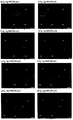
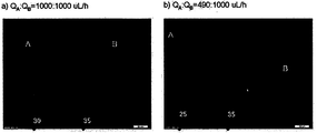
- FIG. 8 is a view showing an image measured for detecting the number of each fluid filled in the counting channel according to the change in the flow rate ratio of the two fluids having the same viscosity to experimentally verify the derived theoretical equation for the fluid viscosity measuring apparatus of the present invention ,
- 10 is a view for explaining a method for measuring the viscosity by adjusting the injection flow rate ratio of the two fluids in order to fix the number of channels filled in the counting channel with the measurement fluid and the reference fluid;
- FIG. 11 is a view for explaining a method of moving an interface between two fluids at an electrode position for detecting an interface by adjusting an injection flow rate ratio between a measurement target fluid and a reference fluid;
- FIG. 16 illustrates four viscosity conditions using four SDS concentrations (2.5%, 5%, 7.5%, and 10%), using the method proposed in the present invention and a commercial viscometer (conventional HAAKE MARS).
- FIG. 1 is a schematic diagram of a fluid viscosity measuring device according to a preferred embodiment of the present invention.
- the fluid viscosity measuring device 1 may include fluid inlets 11 and 12, a connecting pipe 20, a counting channel 30, and the like. .
- the fluid injection part includes a first fluid injection part 11 into which a measurement target fluid A to measure viscosity is injected, and a second fluid injection part 12 into which a reference fluid B having a reference viscosity is injected. It may include.
- the reference fluid (B) which already knows the viscosity, is a fluid which is not mixed with the measurement target fluid (A), and a Newtonian fluid having a constant viscosity regardless of the shear rate is used.
- the reference fluid (B) is a Newton behavior when the fluid to be measured (A) is a non-Newtonian fluid, for example blood (Blood), the viscosity changes according to the shear rate
- PBS Phosphate Buffered Saline
- the fluid viscosity measuring apparatus 1 can simultaneously measure the viscosity for a Newtonian fluid having a constant viscosity and a non-Newtonian fluid whose viscosity varies depending on the shear rate regardless of the shear rate.
- a pump (not shown) and a valve (not shown) may be used to inject the measurement target fluid A and the reference fluid B into the first fluid injection part 11 and the second fluid injection part 12, respectively. It can be provided.
- the connecting tube 20 interconnects the first fluid inlet 11 and the second fluid inlet 12.
- the connecting pipe 20 is provided in a tube shape in which flow paths of the fluid A and the reference fluid B are formed.
- the connection pipe 20 is provided in a rectangular cylindrical shape having a rectangular cross-sectional shape, unlike the present invention may be provided in a circular and polygonal cross-sectional shape.
- the counting channel 30 is disposed in communication with the connection pipe 20 at predetermined intervals, and is provided in plural so that the measurement object fluid A and the reference fluid B flowing on the connection pipe 20 flow paths may be filled, respectively. .
- the counting channel 30 is disposed in the transverse direction of the flow direction of the measurement target fluid A and the reference fluid B in the connection pipe 20, that is, the direction perpendicular to the connection pipe 20.
- the flow characteristics of the fluid to be measured (A) and the reference fluid (B), in particular, the viscosity of the two fluids (A, B) under the condition that the fluid resistance is relatively higher than the fluid resistance of the connecting pipe (20) counting channel (30) ) To be determined.
- the counting channel 30 is a MEMS can be produced in a rectangular and arbitrary shape of the cross-sectional area of the channel.
- FIG. 2 is a view for explaining the principle of measuring the viscosity of the fluid using the fluid viscosity measuring device of the present invention.
- the number of channels changes. Using this, namely, the number N A , N B of counting channels 30 filled by the measurement target fluid A and the reference fluid B , and the measurement target fluid A and the reference fluid B
- the viscosity (m A ) of the fluid (A) to be measured can be calculated using the injection flow rates (Q A , Q B ).
- FIG. 3 is a view for explaining the mathematical modeling of the fluid viscosity measuring device of the present invention.
- the viscosity (m A ) of the measurement target fluid (A) is counted by the viscosity (m B ) of the reference fluid ( B ), the measurement target fluid (A) and the reference fluid (B). It is determined by the number N A , N B of the channels 30, the injection flow rates Q A , Q B of the measurement target fluid A and the reference fluid B.
- 3 (a) is mathematical modeling considering the fluid resistances R m, A and R m, B generated in the connecting pipe 20 by the injection of the measurement target fluid A and the reference fluid B. to be. Instead of this modeling, if the connector 20 is designed to ignore the pressure drop caused by the friction loss caused by the measurement target fluid A and the reference fluid B in the connector 20, as shown in FIG.
- the connection tube to have a certain pressure drop occurs a counting channel 30 arranged perpendicularly to 20, the relationship of the measurement object fluid (a) viscosity (m a) and a reference fluid (B) viscosity (m B) of the Can be simply derived, the number of counting channels (N A , N B ) filled by the measurement target fluid (A) and the reference fluid (B), the measurement target fluid (A) and the reference fluid ( It can be expressed as the injection flow rate (Q A , Q B ) of B ).
- the relation of the viscosity (m A ) of the fluid (A) to be measured is a relation between the pressure drop (DP) and the flow rate (Q),
- Equation (6) substituting the fluid resistance relation (5) for the channel having a low aspect ratio into Equation (4) is as in Equation (6).
- equation (6) can be simply summarized as in equation (7).
- the viscosity m A of the fluid A to be measured can be calculated based on Equation (8).
- Equation (8) When Equation (8) is expressed as Equation (9), the relative viscosity ratio (m A / m B ) of the two fluids (A, B) is counted by the fluid to be measured (A) and the reference fluid (B). It refers to the slope of the injection flow rate ratio Q A / Q B of the two fluids A and B to the number ratio N A / N B of the channel 30.
- Equation (9) is derived in a condition that the friction loss in the connecting pipe (20) is relatively negligible compared to the counting channel (30). In order to find a condition that satisfies this assumption, Equation (9) can be represented schematically as shown in FIG.
- N A / N B is a theoretical description of the number of channels (N A / N B ) filled in the counting channel 30 according to the injection flow rate (Q A / Q B ) of the measurement target fluid (A) and the reference fluid (B) This is a graph.
- CASE (a) and (b) refers to the relative viscosity ratio (m A / m B ) of the two fluids (A, B) compared to CASE (c) that satisfies the condition (9)
- the slope is relatively small. This is due to the frictional loss in the connection pipe 20, in order to reduce this, the fluid resistance of the connection pipe 20 should be reduced. That is, the condition that satisfies Equation (9) can be achieved by increasing the fluid resistance ratio of the connector 20 and the counting channel 30.
- FIG. 5 is a view for explaining the variables (L m , W m , H m ) related to the fluid resistance of the connector and the variables (L c , W c , H c ) related to the fluid resistance of the counting channel.
- the fluid resistance R of the connecting pipe 20 and the counting channel 30 is affected by the cross-sectional area (width W, height H) and length L.
- L c , W c , H c means the length, width, height of the counting channel 30
- L m , W m , H m means the length, width, height of the connector (20). That is, according to the fluid resistance ratio relation (10), the influence of the height (H m , H c ) of the connecting pipe 20 and the counting channel 30 is relatively high, and from this relation the fluid resistance ratio (R c) / R m ) can be calculated.
- the number of counting channels 30 filled with the two fluids (A, B) is equal to 25, but Figure 6 (b)
- the injection flow rate (Q B ) of the reference fluid (B) is 10 times larger than the injection flow rate (Q A ) of the measurement target fluid (A)
- the measurement target fluid (A) and the reference fluid (B) are respectively counting channels (
- the designed fluid viscosity measuring device generates a lot of frictional losses in the connecting pipe, and thus, inevitably, many measurement errors occur when the viscosity is calculated using Equation (9).
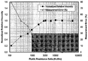
- Relative viscosity (m A / S) which is the slope of the injection flow rate ratio (Q A / Q B ) of the two fluids (A, B) to the channel number ratio (N A / N B ) of the two filled fluids (A, B) m B , relative viscosity) is shown in FIG. 7.
- Normalized relative viscosity ([m A / m B ] expected / [m A / m B ] known ) converges to 1 under the condition that the fluid resistance ratio (R c / R m ) is more than 3000, using equation (9) Viscosity calculation error is less than 1%, showing that the viscosity can be measured accurately. If the fluid resistance ratio (R c / R m ) is 3000 or more, the viscosity measurement error converges to less than 1%, so there is no need to set an upper limit, but the upper limit of the fluid resistance ratio (R c / R m ) is less than 1 million. It is desirable to design under conditions.
- the fluid resistance ratio R c / R m of the connecting pipe 20 and the counting channel 30 is It is preferable to select more than 1000. That is, the fluid resistance (R m ) of the connecting pipe (20) is counted so as to reduce the friction loss between the measurement target fluid (A) and the reference fluid (B) in the connecting pipe (20) and to generate most of the counting channel (30). It is set at least 1000 times smaller than the fluid resistance R c of the channel 30.
- the fluid resistance ratio (R c / R m ) is determined by six variables (L c , W c , H c, L m , W m , H m ) as shown in equation (10).
- FIG. 8 shows the same viscosity (E) to experimentally verify the induced viscosity relation (8) using a fluid viscosity measuring device in which the fluid resistance ratio R c / R m of the connecting pipe and the counting channel 30 is designed to be 6300.
- FIG. 9 illustrates the number of channels N A filled in the counting channel 30 by the measurement target fluid A according to the flow rate ratio Q B / Q A of the two fluids A and B using the experimental result of FIG. 8.
- Experimental and theoretical results, and the normalized deviation of the two methods that is, the experimental results and the theoretical prediction results show sufficient accuracy within 1% on average.
- FIG. 10 is a view for explaining a method for measuring the viscosity by adjusting the injection flow rate ratio of the two fluids in order to fix the number of channels filled in the counting channel with the measurement fluid and the reference fluid.
- the fluid viscosity measuring apparatus 1 measures the number of each counting channel 30 filled by the measurement target fluid A and the reference fluid B.
- FIG. It may include an interface measuring unit 40 for measuring.
- the interface measuring unit 40 may include a measurement target fluid measuring unit, a reference fluid measuring unit, and a fixed boundary measuring unit.
- the measurement target fluid measurement unit is electrically connected to the first electrode 41 and the first electrode 41 provided in any one of the counting channels 30 filled with the measurement target fluid A, and the first electrode ( The first resistance detector 42 detects the resistance of 41.
- the reference fluid measuring unit is electrically connected to the second electrode 43 and the second electrode 43 provided in any one of the counting channels 30 filled with the reference fluid B, and the second electrode 43. Is a second resistance detector 44 for detecting the resistance of?).
- the fixed boundary measurement unit may change the injection flow ratios of the measurement target fluid A and the reference fluid B to move the boundary surfaces of the two fluids A and B while detecting the fixed boundary surfaces, so as to detect the fixed boundary surfaces.
- a third electrode 45 provided in any one of the counting channels 30 between the two electrodes 43, and a third electrically connected to the third electrode 45 to detect resistance of the third electrode 45. It is a resistance detector 46.
- the electrical resistance varies depending on the fluid A to be measured, it is accurate to detect the resistance for each counting channel 30. To this end, the same number of resistance detectors as the number of counting channels 30 is required. In this case, many resistance detectors are installed and signal processing is performed using them, which is inefficient.
- the fixed boundary surface measuring units 45 and 46 are provided, and the interface between the two fluids A and B is adjusted by appropriately adjusting the injection flow rates of the two fluids A and B. It is a method of adjusting to exist in the measuring part 45.46.
- the two fluids A and B injected are counted. Since the number of channels filled in (30) is fixed, and the injection flow rates of the measurement target fluid (A) and the reference fluid (B) respectively injected are known, the viscosity of the measurement target fluid (A) is determined by using the viscosity relationship (8). Viscosity (m A ) can be measured.
- FIG. 11 is a view for explaining a method of moving a boundary between two fluids to a fixed boundary measuring unit by appropriately adjusting the injection flow rate ratio between the measurement target fluid and the reference fluid.
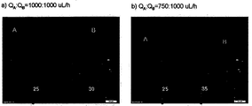
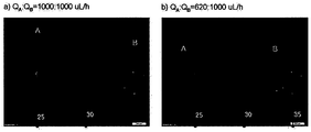
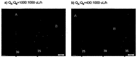
- FIGS. 12 (a), 13 (a), 14 (a) and 15 (a) show the flow rates Q A of the measurement target fluid A and the flow rates of the reference fluid B ( Q B ) is measured at 1000 mL / h, respectively, and FIGS. 12 (b), 13 (b), 14 (b) and 15 (b) show that the measurement target fluid A is counting channel 30.
- the viscosity measured by the fluid viscosity measuring device 1 proposed in the present invention with respect to the viscosity measured under four SDS concentration conditions is averaged compared to the viscosity measured by the conventional HAAKE MARS viscometer. Since it is very accurate to within 4.0%, the fluid viscosity measuring device of the present invention shows that the viscosity measurement can be precise.
- the present invention can be used in the viscometer industry based on microfluidic devices capable of accurately measuring the viscosity for a variety of fluids, including Newtonian fluids as well as non-Newtonian fluids such as Blood.
Landscapes
- Physics & Mathematics (AREA)
- Health & Medical Sciences (AREA)
- Life Sciences & Earth Sciences (AREA)
- Chemical & Material Sciences (AREA)
- Analytical Chemistry (AREA)
- Biochemistry (AREA)
- General Health & Medical Sciences (AREA)
- General Physics & Mathematics (AREA)
- Immunology (AREA)
- Pathology (AREA)
- Measuring Volume Flow (AREA)
Abstract
Description


Claims (12)
- 점도(viscosity)를 측정하고자 하는 측정대상유체가 주입되는 제 1 유체 주입부 및 기준 점도를 가지는 기준유체가 주입되는 제 2 유체 주입부;상기 제 1 유체 주입부와 상기 제 2 유체 주입부를 상호 연결하며, 상기 측정대상유체 및 상기 기준유체의 유로를 형성하는 연결관;상기 연결관에 일정 간격으로 연통 배치되며, 상기 연결관 유로 상으로 유동되는 상기 측정대상유체 및 상기 기준유체가 각각 채워지는 복수 개의 카운팅채널; 및상기 측정대상유체와 상기 기준유체에 의해 채워지는 각각의 상기 카운팅채널의 개수를 측정하기 위한 경계면측정부를 포함하는 유체 점도 측정 장치.
- 제 1 항에 있어서, 상기 카운팅채널은 상기 연결관에 수직방향으로 형성되는 것을 특징으로 하는 유체 점도 측정 장치.
- 제 1 항에 있어서, 상기 연결관과 상기 카운팅채널의 유체저항비를 증가시켜 상기 측정대상유체와 상기 기준유체의 정규화 상대점도비(normalized relative viscosity)가 1에 수렴되도록 하는 것을 특징으로 하는 유체 점도 측정 장치.
- 제 3 항에 있어서, 상기 측정대상유체와 상기 기준유체의 마찰손실이 대부분 상기 카운팅채널에서 발생하도록 상기 연결관의 유체저항을 상기 카운팅채널의 유체저항보다 적어도 1000배 이상 작게 설정하는 것을 특징으로 하는 유체 점도 측정 장치.
- 제 1 항에 있어서, 상기 측정대상유체와 상기 기준유체에 의해 채워지는 상기 카운팅채널의 개수비와, 상기 측정대상유체와 상기 기준유체의 주입유량비를 이용하여 상기 측정대상유체의 점도를 측정하는 것을 특징으로 하는 유체 점도 측정 장치.
- 제 5 항에 있어서, 상기 측정대상유체의 점성 계수는 이하 수학식에 기초하여 계산되는 것을 특징으로 하는 유체 점도 측정 장치.
 : 측정대상유체의 점성계수
 : 기준유체의 점성계수
 : 측정대상유체에 의해 채워지는 카운팅채널의 개수
 : 기준유체에 의해 채워지는 카운팅채널의 개수
 : 측정대상유체의 주입유량
 : 기준유체의 주입유량
- 제 1 항에 있어서, 상기 측정대상유체는 전단률(Shear Rate)에 따라 점도가 변화되는 비뉴턴 유체(non-Newtonian Fluid)를 포함하고, 상기 기준유체는 전단률에 관계없이 일정한 점도를 가지는 뉴턴 유체(Newtonian Fluid)를 포함하는 것을 특징으로 하는 유체 점도 측정 장치.
- 제 7 항에 있어서, 상기 측정대상유체는 혈액(Blood)이고, 상기 기준유체는 인산완충식식염수(Phosphate Buffered Saline, PBS)인 것을 특징으로 하는 유체 점도 측정 장치.
- 제 1 항에 있어서, 상기 측정대상유체와 상기 기준유체는 전단률에 관계없이 일정한 점도를 가지는 뉴턴 유체를 포함하는 것을 특징으로 하는 유체 점도 측정 장치.
- 제 9 항에 있어서, 상기 측정대상유체는 SDS 용액(SDS solution)이고, 상기 기준유체는 초순수(DI water)인 것을 특징으로 하는 유체 점도 측정 장치.
- 제 1 항에 있어서, 상기 경계면측정부는,상기 측정대상유체가 채워지는 상기 카운팅채널 중 어느 하나에 마련되는 제 1 전극, 및 상기 제 1 전극과 전기적으로 연결되어 상기 제 1 전극의 저항을 검출하는 제 1 저항 검출부;상기 기준유체가 채워지는 상기 카운팅채널 중 어느 하나에 마련되는 제 2 전극, 및 상기 제 2 전극과 전기적으로 연결되어 상기 제 2 전극의 저항을 검출하는 제 2 저항 검출부; 및상기 측정대상유체와 상기 기준유체의 주입유량비를 변경하여 두 유체의 경계면을 이동시키면서 고정 경계면을 검출하기 위하여 상기 제 1 전극과 상기 제 2 전극 사이의 상기 카운팅채널 중 어느 하나에 마련되는 제 3 전극, 및 상기 제 3 전극과 전기적으로 연결되어 상기 제 3 전극의 저항을 검출하는 제 3 저항 검출부를 포함하는 유체 점도 측정 장치.
- 점도(viscosity)를 측정하고자 하는 측정대상유체가 주입되는 제 1 유체 주입부 및 기준 점도를 갖는 기준유체가 주입되는 제 2 유체 주입부;상기 제 1 유체 주입부와 상기 제 2 유체 주입부를 상호 연결하며, 상기 측정대상유체 및 상기 기준유체의 유로를 형성하는 연결관; 및상기 연결관에 일정 간격으로 연통 배치되며, 상기 연결관 유로 상으로 유동되는 상기 측정대상유체 및 상기 기준유체가 각각 채워지는 복수 개의 카운팅채널을 포함하며,상기 측정대상유체와 상기 기준유체의 마찰손실이 대부분 상기 카운팅채널에서 발생하도록 상기 연결관의 유체저항을 상기 카운팅채널의 유체저항보다 적어도 1000배 이상 작게 설정하는 것을 특징으로 하는 유체 점도 측정 장치.
Priority Applications (2)
| Application Number | Priority Date | Filing Date | Title |
|---|---|---|---|
| JP2012554887A JP5430041B2 (ja) | 2010-02-23 | 2010-08-19 | 流体粘度測定装置 |
| US13/580,819 US9097634B2 (en) | 2010-02-23 | 2010-08-19 | Fluid viscosity measuring device |
Applications Claiming Priority (2)
| Application Number | Priority Date | Filing Date | Title |
|---|---|---|---|
| KR10-2010-0016104 | 2010-02-23 | ||
| KR20100016104A KR101123959B1 (ko) | 2010-02-23 | 2010-02-23 | 유체 점도 측정 장치 |
Publications (1)
| Publication Number | Publication Date |
|---|---|
| WO2011105668A1 true WO2011105668A1 (ko) | 2011-09-01 |
Family
ID=44507052
Family Applications (1)
| Application Number | Title | Priority Date | Filing Date |
|---|---|---|---|
| PCT/KR2010/005498 Ceased WO2011105668A1 (ko) | 2010-02-23 | 2010-08-19 | 유체 점도 측정 장치 |
Country Status (4)
| Country | Link |
|---|---|
| US (1) | US9097634B2 (ko) |
| JP (1) | JP5430041B2 (ko) |
| KR (1) | KR101123959B1 (ko) |
| WO (1) | WO2011105668A1 (ko) |
Families Citing this family (5)
| Publication number | Priority date | Publication date | Assignee | Title |
|---|---|---|---|---|
| KR101477919B1 (ko) * | 2013-08-28 | 2014-12-30 | 김보곤 | 혈액점도측정용 이미지 분석방법 |
| KR101681170B1 (ko) | 2015-11-02 | 2016-12-01 | 조선대학교산학협력단 | 혈액의 생물성치 측정용 미세유체기구 |
| JP6692077B2 (ja) * | 2016-01-27 | 2020-05-13 | 国立大学法人九州工業大学 | 体液粘性測定装置 |
| KR102034540B1 (ko) * | 2017-09-25 | 2019-10-21 | 주식회사 큐리오시스 | 점도계 |
| US12540538B2 (en) | 2023-12-22 | 2026-02-03 | Profrac Holdings Ii, Llc | Monitoring friction of a fracture treatment fluid |
Citations (4)
| Publication number | Priority date | Publication date | Assignee | Title |
|---|---|---|---|---|
| JPH06241852A (ja) * | 1993-02-12 | 1994-09-02 | Kazuhiro Okada | 流量/粘度の測定方法および測定装置 |
| JP2003515123A (ja) * | 1999-11-12 | 2003-04-22 | レオロジクス インコーポレイテッド | デュアル上昇管/シングル毛細管粘度計 |
| US20060093488A1 (en) * | 2004-10-15 | 2006-05-04 | Wong Teck N | Method and apparatus for controlling multi-fluid flow in a micro channel |
| KR100741262B1 (ko) * | 2006-05-18 | 2007-07-19 | 포항공과대학교 산학협력단 | 마이크로 점도계 |
Family Cites Families (7)
| Publication number | Priority date | Publication date | Assignee | Title |
|---|---|---|---|---|
| JP3248683B2 (ja) | 1998-01-20 | 2002-01-21 | 富士工業株式会社 | 液体の密度と粘度の分離測定方法及び装置 |
| US6622746B2 (en) * | 2001-12-12 | 2003-09-23 | Eastman Kodak Company | Microfluidic system for controlled fluid mixing and delivery |
| KR20020095145A (ko) * | 2002-11-26 | 2002-12-20 | 신세현 | 마이크로 점도계 및 측정방법 |
| KR20030008223A (ko) * | 2003-01-08 | 2003-01-24 | 신세현 | 진공 점도계 |
| FR2879290B1 (fr) * | 2004-12-10 | 2007-02-02 | Rhodia Chimie Sa | Procede et installation de determination de caracteristiques rheologiques d'un fluide, et procede d'identification correspondant |
| JP5200507B2 (ja) * | 2007-11-30 | 2013-06-05 | 東ソー株式会社 | 液体クロマトグラフ用粘度計 |
| KR101123960B1 (ko) * | 2009-10-07 | 2012-03-23 | 광주과학기술원 | 유체 점도 측정 장치 |
-
2010
- 2010-02-23 KR KR20100016104A patent/KR101123959B1/ko active Active
- 2010-08-19 US US13/580,819 patent/US9097634B2/en active Active
- 2010-08-19 WO PCT/KR2010/005498 patent/WO2011105668A1/ko not_active Ceased
- 2010-08-19 JP JP2012554887A patent/JP5430041B2/ja active Active
Patent Citations (4)
| Publication number | Priority date | Publication date | Assignee | Title |
|---|---|---|---|---|
| JPH06241852A (ja) * | 1993-02-12 | 1994-09-02 | Kazuhiro Okada | 流量/粘度の測定方法および測定装置 |
| JP2003515123A (ja) * | 1999-11-12 | 2003-04-22 | レオロジクス インコーポレイテッド | デュアル上昇管/シングル毛細管粘度計 |
| US20060093488A1 (en) * | 2004-10-15 | 2006-05-04 | Wong Teck N | Method and apparatus for controlling multi-fluid flow in a micro channel |
| KR100741262B1 (ko) * | 2006-05-18 | 2007-07-19 | 포항공과대학교 산학협력단 | 마이크로 점도계 |
Also Published As
| Publication number | Publication date |
|---|---|
| US20130036797A1 (en) | 2013-02-14 |
| KR101123959B1 (ko) | 2012-03-23 |
| JP2013520676A (ja) | 2013-06-06 |
| KR20110096714A (ko) | 2011-08-31 |
| JP5430041B2 (ja) | 2014-02-26 |
| US9097634B2 (en) | 2015-08-04 |
Similar Documents
| Publication | Publication Date | Title |
|---|---|---|
| WO2011105668A1 (ko) | 유체 점도 측정 장치 | |
| US7242474B2 (en) | Cytometer having fluid core stream position control | |
| US20190178837A1 (en) | Sensing device and method in detecting binding affinity and binding kinetics between molecules | |
| Atwood et al. | Measurements of slip at the wall during flow of high-density polyethylene through a rectangular conduit | |
| WO2015060664A1 (en) | Multi sampling port monitoring apparatus for measuring pollution level and monitoring method using the same | |
| CN109738030B (zh) | 压力位差式层流流量测量方法及装置 | |
| WO2017171331A1 (ko) | 교정장치 및 이를 구비한 가스성분 분석장치 | |
| CN108827834B (zh) | 一种微米毛细管通道中气液相界面的获取方法 | |
| WO2013100244A1 (ko) | 표면장력 측정 장치 및 측정 방법 | |
| EP0059726B1 (en) | Water purity measurement | |
| CN107389502A (zh) | 一种测量液体粘度的方法及系统 | |
| CN115436228A (zh) | 一种用于测量微升级液体样品粘度的系统及方法 | |
| CN219712674U (zh) | 一种多通道气路快速拔插集中密封装置 | |
| CN109000883A (zh) | 一种确定微米毛细管通道中压力与流量关系的方法 | |
| CN109100485B (zh) | 一种微米毛细管气液动态相界面测试系统 | |
| KR101103626B1 (ko) | 유체 점도 측정 장치 | |
| CN215261903U (zh) | 一种多维层流流体流量测量装置 | |
| CN114295688B (zh) | 一种适用于微通道异质物检测的电阻抗层析成像传感器 | |
| CN107449712B (zh) | 一种通道内检测试剂的方法、装置及细胞分析仪系统 | |
| WO2020014975A1 (zh) | 流体传感器及质量流量控制器 | |
| CN109541248B (zh) | 一种流动注射反应池装置和用于此装置的换向流体单元 | |
| CN114350490A (zh) | 一种用于测量细胞s参数的检测平台及其检测方法 | |
| CN112362896A (zh) | 一种基于磁性材料耦合的流速探测装置 | |
| TWI799926B (zh) | 電化學檢測系統、測量儀及電化學檢測方法 | |
| CN106841120B (zh) | 适用于多通道终端反射式光纤spr传感器的流通池 |
Legal Events
| Date | Code | Title | Description |
|---|---|---|---|
| 121 | Ep: the epo has been informed by wipo that ep was designated in this application |
Ref document number: 10846695 Country of ref document: EP Kind code of ref document: A1 |
|
| NENP | Non-entry into the national phase |
Ref country code: DE |
|
| WWE | Wipo information: entry into national phase |
Ref document number: 2012554887 Country of ref document: JP |
|
| WWE | Wipo information: entry into national phase |
Ref document number: 13580819 Country of ref document: US |
|
| 122 | Ep: pct application non-entry in european phase |
Ref document number: 10846695 Country of ref document: EP Kind code of ref document: A1 |