WO2011105142A1 - Airbag device - Google Patents
Airbag device Download PDFInfo
- Publication number
- WO2011105142A1 WO2011105142A1 PCT/JP2011/051085 JP2011051085W WO2011105142A1 WO 2011105142 A1 WO2011105142 A1 WO 2011105142A1 JP 2011051085 W JP2011051085 W JP 2011051085W WO 2011105142 A1 WO2011105142 A1 WO 2011105142A1
- Authority
- WO
- WIPO (PCT)
- Prior art keywords
- airbag
- cloth
- gas
- foaming agent
- airbag device
- Prior art date
Links
Images


Classifications
-
- B—PERFORMING OPERATIONS; TRANSPORTING
- B60—VEHICLES IN GENERAL
- B60R—VEHICLES, VEHICLE FITTINGS, OR VEHICLE PARTS, NOT OTHERWISE PROVIDED FOR
- B60R21/00—Arrangements or fittings on vehicles for protecting or preventing injuries to occupants or pedestrians in case of accidents or other traffic risks
- B60R21/02—Occupant safety arrangements or fittings, e.g. crash pads
- B60R21/16—Inflatable occupant restraints or confinements designed to inflate upon impact or impending impact, e.g. air bags
- B60R21/23—Inflatable members
- B60R21/235—Inflatable members characterised by their material
-
- B—PERFORMING OPERATIONS; TRANSPORTING
- B60—VEHICLES IN GENERAL
- B60R—VEHICLES, VEHICLE FITTINGS, OR VEHICLE PARTS, NOT OTHERWISE PROVIDED FOR
- B60R21/00—Arrangements or fittings on vehicles for protecting or preventing injuries to occupants or pedestrians in case of accidents or other traffic risks
- B60R21/02—Occupant safety arrangements or fittings, e.g. crash pads
- B60R21/16—Inflatable occupant restraints or confinements designed to inflate upon impact or impending impact, e.g. air bags
- B60R21/23—Inflatable members
- B60R21/231—Inflatable members characterised by their shape, construction or spatial configuration
- B60R2021/23123—Heat protection panels
-
- B—PERFORMING OPERATIONS; TRANSPORTING
- B60—VEHICLES IN GENERAL
- B60R—VEHICLES, VEHICLE FITTINGS, OR VEHICLE PARTS, NOT OTHERWISE PROVIDED FOR
- B60R21/00—Arrangements or fittings on vehicles for protecting or preventing injuries to occupants or pedestrians in case of accidents or other traffic risks
- B60R21/02—Occupant safety arrangements or fittings, e.g. crash pads
- B60R21/16—Inflatable occupant restraints or confinements designed to inflate upon impact or impending impact, e.g. air bags
- B60R21/23—Inflatable members
- B60R21/235—Inflatable members characterised by their material
- B60R2021/23504—Inflatable members characterised by their material characterised by material
- B60R2021/23509—Fabric
-
- B—PERFORMING OPERATIONS; TRANSPORTING
- B60—VEHICLES IN GENERAL
- B60R—VEHICLES, VEHICLE FITTINGS, OR VEHICLE PARTS, NOT OTHERWISE PROVIDED FOR
- B60R21/00—Arrangements or fittings on vehicles for protecting or preventing injuries to occupants or pedestrians in case of accidents or other traffic risks
- B60R21/02—Occupant safety arrangements or fittings, e.g. crash pads
- B60R21/16—Inflatable occupant restraints or confinements designed to inflate upon impact or impending impact, e.g. air bags
- B60R21/26—Inflatable occupant restraints or confinements designed to inflate upon impact or impending impact, e.g. air bags characterised by the inflation fluid source or means to control inflation fluid flow
- B60R21/261—Inflatable occupant restraints or confinements designed to inflate upon impact or impending impact, e.g. air bags characterised by the inflation fluid source or means to control inflation fluid flow with means other than bag structure to diffuse or guide inflation fluid
- B60R2021/2612—Gas guiding means, e.g. ducts
- B60R2021/2617—Curtain bag nozzles
-
- B—PERFORMING OPERATIONS; TRANSPORTING
- B60—VEHICLES IN GENERAL
- B60R—VEHICLES, VEHICLE FITTINGS, OR VEHICLE PARTS, NOT OTHERWISE PROVIDED FOR
- B60R21/00—Arrangements or fittings on vehicles for protecting or preventing injuries to occupants or pedestrians in case of accidents or other traffic risks
- B60R21/02—Occupant safety arrangements or fittings, e.g. crash pads
- B60R21/16—Inflatable occupant restraints or confinements designed to inflate upon impact or impending impact, e.g. air bags
- B60R21/23—Inflatable members
- B60R21/231—Inflatable members characterised by their shape, construction or spatial configuration
- B60R21/232—Curtain-type airbags deploying mainly in a vertical direction from their top edge
Definitions
- the present invention is an airbag device that is mounted on a vehicle such as an automobile and inflates and deploys an airbag with gas supplied from an inflator to protect an occupant, and in particular, efficiently damages the airbag due to gas supplied from the inflator.
- the present invention relates to an airbag device that is capable of preventing and protecting an occupant more reliably, and that is lightweight and excellent in storage.
- an airbag device equipped with an airbag that can be inflated and deployed is mounted on the steering wheel or instrument panel, for example.
- Automobiles are widely used. When the front of the automobile collides with another automobile or an obstacle (frontal collision), it is possible to rapidly inflate the bag body between the occupant and the vehicle interior structure to ensure the safety of the occupant.
- a curtain airbag device that is inflated so as to cover a side window portion at the time of a collision when the curtain airbag stored in a folded state is being installed in earnest.
- Patent Document 1 As an example of such an airbag device, one disclosed in Patent Document 1 is known.
- the airbag device described in Patent Document 1 is provided with an airbag attached to a roof rail portion or the like on the side of the vehicle, and the airbag is inflated and deployed so as to cover the vehicle wall by closing the opening inside the vehicle with the gas from the inflator. And protect the head mainly for the front and rear passengers.
- a cylinder type inflator is used, a metal guide tube (guide tube portion) is fixed to the outer periphery of the cylindrical main body portion, and a plurality of gas ejection ports at one end portion are enclosed, The tip opening of the guide tube is inserted into the airbag, and an inflator is attached to the gas inlet of the airbag.
- the airbag device guides, for example, a gas ejected radially from the gas ejection port to the inner tube in the airbag, and supplies the gas into the airbag through them to inflate and deploy the airbag.
- This metal guide tube also has a function to protect the airbag by relieving the pressure of the gas ejected from the gas ejection port of the inflator or preventing the gas from being directly injected to the base fabric. .
- Patent Document 2 includes an airbag that can be inflated and deployed so as to cover a vehicle wall by introducing gas, and an inflator that ejects gas radially from a plurality of gas ejection ports and supplies the gas into the airbag.
- An airbag is an airbag device having a gas inlet port to which an inflator is attached and an air chamber that is inflated by gas from the gas inlet port, and surrounds the plurality of gas ejection ports and faces into the airbag.
- An airbag device is disclosed that includes a cloth-like member wound around an inflator a plurality of times so as to open. Without providing a heavy metal guide tube on the inflator of the airbag device, a lightweight and flexible cloth-like member can be used to guide the gas supplied from the gas outlet and protect the airbag from the gas. can do.
- the weight reduction is indispensable for all the members.
- air bag devices efforts are being made to reduce the weight, and as one of them, it is considered to reduce the size and weight of the inflator.
- the thermal load on the airbag Tend is required to increase.
- the airbag is required to function even in a high temperature environment, for example, at 80 ° C., and the thermal load is further increased due to the severe environment.
- Patent Document 1 In order to prevent damage to the airbag due to a thermal load, as disclosed in Patent Document 1, it has been studied to use a metal guide tube, but the metal guide tube protects the airbag. Although the performance is high, the weight is large, which is contrary to the demand for weight reduction of the airbag device. Moreover, since it is necessary to caulk and fix the metal guide tube on the outer periphery of the inflator, there is a tendency for the labor required for attachment to the inflator to increase.
- the coating base fabric coated with synthetic rubber such as chloroprene, chlorosulfonated olefin, silicone, etc. is used for the air bag, such as heat resistance, air barrier (low breathability), flame resistance, etc.
- the base fabric coated with synthetic rubber is used as a base fabric for airbags because the weight of the base fabric increases, the flexibility is not satisfactory, and the manufacturing cost is high. There were a lot of things that did't enough.
- the present invention can increase the heat resistance of the airbag and can be inflated and deployed enough to protect an occupant even when a lightweight and small inflator that ejects high-temperature gas is used in a high-temperature environment.
- a first aspect of the present invention includes an airbag that can be inflated and deployed by introducing gas, an inflator that ejects gas from a gas ejection port and supplies the gas into the airbag, and a gas ejection that opens into the airbag
- An airbag device is provided that includes a cloth-like member that surrounds the mouth and includes at least a non-molten fiber.
- an airbag apparatus comprising: an airbag that can be inflated and deployed by introducing gas; and an inflator that ejects gas from a gas ejection port and supplies the gas into the airbag.
- At least a synthetic resin to which a foaming agent is added adheres, especially the synthetic resin adheres in a specific manner, specifically, at least 50% or more of the warp / weft crossing surface and the single yarn constituting the yarn
- a synthetic resin to which at least a foaming agent is added is attached to the surface layer to the fifth layer.
- the air bag device of the present invention is a lightweight, small and high temperature without using a metal guide tube or overlapping multiple layers of cloth-like members even when using an inflator that ejects extremely high temperature gas. Since the airbag can be protected from the gas, it is lightweight and has excellent storage properties. Further, the structure of the airbag device can be simplified, and the manufacturing cost can be reduced. In addition, the synthetic resin added with the foaming agent is attached not only to the surface of the warp and weft intersection, but also to the surface layer to the fifth layer of the single yarn composing the yarn, so the high temperature gas is in the airbag. When in contact with the foaming agent, the foaming agent foams to generate gas.
- the heat insulation and cooling effect of the foam layer and gas is manifested not only on the fabric surface but also inside the yarn, improving the heat resistance of the airbag and reducing thermal damage even when hot gas contacts the airbag can do. Therefore, inflating and deployment sufficient to protect the occupant is possible.
- the synthetic resin adheres in a specific manner, the air permeability at a low pressure, for example, 100 kPa differential pressure is 5 cc / cm 2 / sec or less, and the flexibility, for example, a rigid measured by a cantilever method. It is possible to simultaneously satisfy the softness of 100 mm or less.
- FIG. 1 It is a figure which shows the example of the airbag apparatus which concerns on this invention. It is a figure which shows an example of the woven structure of the boundary vicinity with the expansion part of an inner side junction part. It is a figure which shows an example of the woven structure inside from the boundary vicinity with the expansion part of an inner side junction part. It is a figure which shows the example of a shape of a dot-shaped inner side junction part. It is explanatory drawing of the warp direction of the cloth which comprises a curtain bag. It is the elements on larger scale which show Z area
- An airbag apparatus includes an airbag that can be inflated and deployed by introducing gas, an inflator that ejects gas from a gas ejection port and supplies the gas into the airbag, and an opening in the airbag. As described above, the gas ejection port is surrounded and a cloth-like member including at least non-melting fiber is provided.
- An airbag apparatus is an airbag apparatus including an airbag that can be inflated and deployed by introducing gas, and an inflator that ejects gas from a gas ejection port and supplies the gas into the airbag.
- the synthetic resin which added the foaming agent at least to the bag adheres. In particular, synthetic resin adheres in a specific manner. Specifically, at least 50% or more of the warp / weft crossing surface and the surface layer to the fifth layer of the single yarn constituting the yarn are added to at least a foaming agent. The synthetic resin is attached.
- a cloth-like member containing at least non-melting fibers which surrounds the gas ejection port of the inflator and opens into the airbag.
- a cloth-like member a known cloth-like article such as a woven fabric, a knitted fabric, or a non-woven fabric can be used, but a woven fabric excellent in high-temperature gas barrier properties is preferable.
- the structure of the woven fabric is not particularly limited, and a known structure can be used.
- the non-melting fiber means a fiber in which a clear endothermic peak accompanying melting is not observed in heat measurement by DSC (differential scanning calorimetry).
- DSC differential scanning calorimetry
- the non-melt fiber include, but are not limited to, cellulosic fibers, acrylic fibers, aramid fibers, vinylon fibers, carbon fibers, ceramic fibers, and animal natural fibers.
- the cloth-like member preferably contains at least one of cellulose fiber, acrylic fiber, aramid fiber, vinylon fiber, carbon fiber, ceramic fiber, and animal natural fiber. Cellulosic fibers, acrylic fibers, and animal natural fibers are particularly preferable in view of good handling properties such as safety and low cost. It is also preferable to mix two or more types of non-melt fibers.
- Cellulosic fibers are fibers mainly composed of cellulose, and examples thereof include natural fibers such as cotton, hemp, and jute, and regenerated fibers such as rayon, lyocell, and cupra.
- An acrylic fiber is a fiber containing 35% or more of acrylonitrile or an acrylate fiber obtained by chemically modifying the fiber.
- An aramid fiber is an aromatic amide fiber and includes a para-aramid fiber and a meta-aramid fiber, and a meta-aramid fiber having excellent heat resistance is preferred. Examples of para-aramid fibers include polyparaphenylene terephthalamide, and examples of meta-aramid fibers include polymetaphenylene terephthalamide.
- Vinylon fiber is a general term for fibers obtained by acetalizing polyvinyl alcohol.
- Carbon fiber is a fiber made by carbonizing acrylic fiber or pitch (by-products such as petroleum, coal, coal tar, etc.) as a raw material at a high temperature, and graphite at an ultra-high temperature of 2,000 ° C. or higher in an inert atmosphere.
- Graphitized fibers are also included.
- the ceramic fiber is a fiber made from a ceramic such as alumina or silicon carbide, and examples thereof include alumina fiber and silicon carbide fiber.
- Animal natural fibers are natural fibers derived from animals, such as animal hair (wool, alpaca, cashmere, etc.), silk, and the like.
- the non-melting fiber may be used alone, but may be used in combination with fibers other than the non-melting fiber.
- the fibers other than the non-melted fibers are not particularly limited, but when the synthetic fibers to be melted are melted by the high-temperature gas, they absorb heat to suppress heat conduction from the high-temperature gas to the airbag. ,preferable. If fibers other than non-molten fibers are used alone, heat conduction is suppressed, but the cloth-like member may be damaged by melting and may not exhibit sufficient airbag protection performance. Thus, damage to the cloth-like member can be suppressed while taking advantage of suppressing heat conduction.
- synthetic fibers such as polyamide and polyester are preferable from the viewpoint of increasing the strength of the cloth-like member.
- the form of mixing non-melted fibers and fibers other than non-melted fibers is not particularly limited, and known forms can be used.
- stacking the cloth which consists it does not specifically limit.
- a cloth made of fibers other than unmelted fibers is used on the gas outlet side of the inflator.
- a mixed form in which a cloth made of non-melting fibers is disposed is preferable.
- the form of the non-melted fiber is not particularly limited and can be used in a known form, but it is preferable to use a short fiber having a large gap between yarns and a high effect of suppressing heat conduction.
- the form of fibers other than the non-melted fiber is not particularly limited, and can be appropriately used in a known form depending on the purpose of use. That is, short fibers are preferably used when importance is placed on the performance of suppressing the heat conduction of the cloth-like member, and long fibers are preferably used when importance is placed on increasing the strength of the cloth-like member.
- the combination of the form of the non-melt fiber and the form of the fiber other than the non-melt fiber is not particularly limited, but the non-melt fiber is a short fiber from the viewpoint of achieving both the effect of suppressing the heat conduction of the cloth-like member and the effect of improving the strength.
- a combination in which fibers other than non-melting fibers are long fibers is preferable.
- the protection time of the cloth-like member against the flame is preferably 3.5 seconds or more, particularly preferably 5 seconds or more, particularly preferably 7 seconds or more.
- the protection time against a flame is a time measured by the method specified in ISO 9151. Specifically, a flame having a constant heat density (80 KW / m2 ⁇ 5%) is given from the lower side of the cloth-like member, The temperature rise with time is measured with a calorimeter attached to the upper side of the member, and the temperature rises by 12 ° C. from before the start of measurement. The longer this time, the less the damage and heat conduction of the cloth-like member when the flame comes into contact, and the higher the protection performance against the flame, which is preferable.
- the cloth-like member of the present invention is preferably subjected to at least one of a flame retardant treatment, a flameproof treatment, a heat-resistant treatment, and a foaming treatment because damage to the cloth-like member due to high-temperature gas is reduced.
- the flame retardant treatment, the flame proof treatment, the heat resistance treatment, and the foaming treatment may be performed on at least one surface of the cloth member. It is preferable that the surface of the cloth-like member on the gas ejection port side of the inflator is subjected to any one of flame retardant treatment, flameproof treatment, heat resistance treatment, and foaming treatment.
- Flame retardant treatment is a treatment that makes a cloth-like member difficult to burn
- flameproof treatment is a treatment that makes it difficult to spread even if a flame is applied.
- the flame retardant treatment is performed by applying a liquid in which a flame retardant is dissolved or dispersed to the surface of the cloth-like member by a known method, for example, a padding method, a spray method, or a coating method.
- the flame retardant is not particularly limited, and a known flame retardant can be used.
- Bromine flame retardants phosphoric esters such as triphenyl phosphate, phosphorus flame retardants such as red phosphorus, chlorinated flame retardants such as chlorinated paraffin, metal hydroxide flame retardants such as aluminum hydroxide and magnesium hydroxide And antimony flame retardants such as antimony pentoxide.
- phosphoric acid esters such as triphenyl phosphate, phosphorus flame retardants such as red phosphorus, metal hydroxide flame retardants such as aluminum hydroxide and magnesium hydroxide are preferred, especially triphenyl phosphate.
- Phosphoric acid esters such as red phosphorus and flame retardants such as red phosphorus are preferred.
- the flameproofing treatment is performed by applying a liquid in which a flameproofing agent is dissolved or dispersed to the surface of the cloth-like member by a known method such as a padding method, a spray method, or a coating method.
- the flameproofing agent is not particularly limited, and a known flameproofing agent can be used.
- aromatic condensed phosphate ester, phosphate ester amide, guanidine phosphate derivative, halogen-containing organic phosphorus compound, guanyl Examples include sulfamide and hexabromocyclododecane.
- Aromatic condensed phosphate esters, phosphate ester amides, and phosphate guanidine derivatives that have a high effect of imparting flameproofing properties to many types of non-melt fibers are preferred.
- the heat resistance treatment is a treatment for improving the heat resistance by providing a heat resistant layer on the surface of the cloth-like member.
- the heat-resistant layer is not particularly limited as long as it improves the heat resistance of the cloth-like member, but examples thereof include heat-resistant resins, rubbers, metal thin films, and metal oxide thin films.
- the heat-resistant resin and rubber include silicone resin or rubber, fluororesin or rubber
- examples of the metal thin film include aluminum thin film, nickel thin film, copper thin film, silver thin film, and gold thin film.
- the metal oxide thin film include an alumina thin film and a titanium oxide thin film.
- a known method can be used as a method for providing the heat-resistant layer, and is not particularly limited.
- examples thereof include a coating method, a laminating method, a padding method, and a spray method.
- a vapor deposition method, a sputtering method, an electroless plating method, and the like are exemplified, and if it is a metal oxide, a vapor deposition method, a sputtering method, and the like are exemplified.
- the foaming treatment is to protect the surface of the cloth-like member by applying a foaming agent to the surface of the cloth-like member and generating a gas from the foaming agent when the cloth-like member comes into contact with a high-temperature gas. This is a process for improving heat resistance.
- a foaming agent for example, a chemical foaming agent or a physical foaming agent can be used.
- a chemical foaming agent is preferred because it can be easily added to a synthetic resin.
- Examples of the chemical foaming agent include inorganic foaming agents such as sodium hydrogen carbonate, ammonium hydrogen carbonate, and ammonium carbonate, such as organic foaming agents such as nitroso compounds, azo compounds, sulfonyl hydrazide compounds, and carbonamide compounds, and physical foaming agents.
- inorganic foaming agents such as sodium hydrogen carbonate, ammonium hydrogen carbonate, and ammonium carbonate
- organic foaming agents such as nitroso compounds, azo compounds, sulfonyl hydrazide compounds, and carbonamide compounds
- physical foaming agents for example, carbon dioxide gas, nitrogen gas, or the like can be used.
- a chemical foaming agent is preferred because it can be easily added to a synthetic resin.
- an organic foaming agent having high affinity with a synthetic resin and excellent dispersibility and processability is preferable.
- the organic foaming agent preferably contains at least N.
- N-containing organic foaming agent examples include nitroso compounds, azo compounds, sulfonyl hydrazide compounds, and carbonamide compounds.
- nitroso compound examples include N, N′-dinitrosopentamethylenetetramine, and the azo compound is not particularly limited as long as it has at least one —N ⁇ N— group in the molecule.
- the sulfonyl hydrazide compound is a compound having at least one —SO 2 —NHNH 2 group in the molecule, although not particularly limited, for example, 4,4′-oxybis (benzenesulfonylhydrazide), p-toluenesulfonylhydrazide, 2,4-toluenedisulfonylhydrazide, p, p-bis (benzenesulfonylhydrazide) ether, benzene-1, 3-disulfonylhydrazide, benzenesulfoni Hydrazide.
- 4,4′-oxybis benzenesulfonylhydrazide
- p-toluenesulfonylhydrazide 2,4-toluenedisulfonylhydrazide
- p p-bis (benzenesulfonylhydrazide) ether
- benzene-1 3-d
- Examples of the carbonamide compound include hydrazodicarbonamide the like.
- An azo compound and a sulfonyl hydrazide compound are preferable from the viewpoint of safety, and an azo compound is preferable from the viewpoint of foaming property, and azodicarbonamide having a foaming temperature of 200 ° C. or higher and excellent storage stability is particularly preferable.
- the airbag apparatus of the present invention includes an airbag that can be inflated and deployed by introducing gas, and an inflator that ejects gas from a gas ejection port and supplies the gas into the airbag. It can be used for known airbags such as for side use. Especially for side surfaces that protect the occupants in a vehicle when a vehicle crashes or rolls over by deploying an air bag in a predetermined range inside the side of the vehicle from the driver's seat or passenger seat to the rear seat on the rear side of the vehicle. It is preferable to use for the airbag apparatus (curtain airbag apparatus).
- a curtain airbag device for protecting the head is taken as an example in which an airbag is inflated and deployed in a curtain shape from the roof rail portion above the side of the vehicle, etc., and mainly protects the head of the passengers in the front and rear seats. Although described, it is not limited to this embodiment.
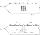
- FIG. 1 is a front view schematically showing a main part of the airbag device of the present embodiment, and is a plan development view showing a schematic shape of the airbag in a deployed state. Further, in FIG. 1, the internal configuration is also shown by seeing through the inside of the airbag.
- the inflator 40 side (the right side of the horizontally long airbag 10 in the figure), which will be described later, is the rear side (rear pillar side) in the vehicle, and the opposite side (the left side of the airbag 10 in the figure) is the front side (front) in the vehicle. Pillar side).
- the airbag 10 is arrange
- the airbag 10 is inflated and deployed so as to cover the entire side window portion (positioned on the back side in the drawing in the figure) (not shown) (not shown) inside the vehicle, and closes the opening in the vehicle. Inflated between the occupant and the vehicle wall.
- the airbag apparatus 1 includes an airbag 10 that can be inflated and deployed so as to cover a vehicle wall by introducing (inflowing) gas, and one end side thereof (here, the vehicle rear side). And an inflator 40 for supplying gas into the airbag 10.
- the airbag device 1 stores the airbag 10 and the inflator 40 in a predetermined state when not in operation, and an airbag cover provided inside the vehicle and a fixing means for fixing the airbag 10 and the inflator 40 to the vehicle.
- Other configurations similar to conventional ones are provided (not shown).
- the airbag 10 has a horizontally long substantially bag shape corresponding to the shape of the vehicle side window portion to be covered, and the like (six in the figure) attached to the roof rail portion of the vehicle along the upper edge. It has a rectangular upper mounting tab 11. Further, the airbag 10 is formed with a substantially triangular front mounting piece 12 that protrudes toward the front side of the vehicle, and a front end portion (a protruding end portion) of the airbag 10 is attached to the front pillar portion of the vehicle.
- the airbag 10 is attached to the vehicle with the mounting pieces 11 and 12 being fixed to a predetermined position in the vehicle by a fixing means such as a bolt, and the airbag cover provided in each part of the vehicle is in a state before being inflated. It is stored and placed inside.
- the airbag 10 is folded in order toward the mounting pieces 11 and 12 (upper edge side) or wound around the vehicle from the lower edge side to the upper edge side so that the airbag 10 can be inflated and deployed in the downward direction. It is stored in.
- the inflator 40 when the inflator 40 is actuated, the airbag 10 is inflated from the stored state to push open the airbag cover, and is inflated and deployed mainly in a curtain shape in the downward direction of the vehicle.
- the airbag 10 it is preferable that at least two cloths are bonded to each other by an outer peripheral joint portion 22 provided at the outer peripheral edge portion and an inner joint portion 23 provided inside the outer peripheral joint portion.
- the method for joining the cloth is not particularly limited, and a known method can be used.
- a sewing machine sewing method in which cloths of a predetermined shape formed by cutting the cloth are overlapped and the joint is sewn with a sewing machine, cloths of a predetermined shape formed by cutting the cloth are overlapped, and the joint is adhesive.
- the cloth used is not particularly limited as long as it satisfies the required characteristics, but is preferably a woven fabric.
- the raw yarn used for the cloth is not particularly limited, since the synthetic fibers such as polyamide, polyester, and acrylic have high strength, the strength of the airbag 10 is increased, which is preferable.
- nylon 66 fiber and polyethylene terephthalate fiber having a high melting point and a large heat capacity are particularly preferable.
- the fineness of the raw yarn is not particularly limited, but is preferably 78 to 940 dTex, and more preferably 235 to 475 dTex. If it is 78 dTex or more, mechanical damage due to gas ejected from the inflator, and thermal damage due to high-temperature gas or combustion residue can be reduced when using a pyro-type inflator or a hybrid-type inflator. Further, if it is 940 dTex or less, it is satisfactory in terms of strength, and even if weaving at a high density, there are many intersections of warp and weft yarns, and it is difficult for the outer joint and inner joint to open due to internal pressure during operation. There is no fear of gas spillage. In addition, the finished fabric is thin and light, and the storage capacity of the airbag 10 is improved.
- the single yarn fineness of the raw yarn is not particularly limited, but is preferably 6 dtex or more and 15 dtex or less. If the single yarn fineness is 6 dtex or more, the specific surface area of the single yarn is reduced when using a pyro type inflator or a hybrid type inflator, so that thermal damage due to high-temperature gas or combustion residue can be reduced. In addition, when water-based synthetic resin is immersed after water impregnation, which will be described later, since the single yarn fineness is large and the gap between the single yarns is wide, the replacement of water and resin is performed smoothly and low air permeability is obtained. Cheap. Moreover, if it is 15 dtex or less, the hardness of a base fabric will also be suppressed.
- the warp at the time of weaving may be used as a normal plain woven fabric when the airbag 10 is manufactured by a sewing machine method or an adhesive method. It is preferable to use after waxing or sizing.
- the warp and the weft of a predetermined part of the two pieces of cloth are interlaced to form the outer joint and the inner joint.
- the woven density of the joint and inner joint is twice that of the expanded part, the load on the warp yarn during weaving is large, the yarn tends to fluff, and weaving defects occur frequently. Therefore, it is preferable to perform sizing.
- the weaving density may be appropriately selected depending on the fineness of the raw yarn to be used. For example, with 470 dTex, the total history is 90 to 110 pieces / 2.54 cm, 350 dTex is around 125 pieces / 2.54 cm, and 235 dTex is 145 pieces / About 2.54 cm is preferable. If it is in this woven density range, weaving becomes easy, and weaving property and textile quality are improved. Moreover, it is possible to withstand the mechanical load caused by the gas ejected from the inflator, and the thermal load can be reduced.
- the weaving density is not necessarily the same as the background, and the density difference may be given in consideration of the weaving efficiency or the direction of the mechanical load due to the gas to be ejected.
- the weave structure of the cloth to be used is not particularly limited, but a plain weave structure is usually used.
- the woven structure of the inflated part except for the outer peripheral joint part, the inner joint part, and the vicinity of the boundary between the joint part and the inflated part is not particularly limited, but a plain woven structure is usually used.
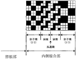
- the woven structure of the joint part in the vicinity of the boundary with the inflating part is not particularly limited.
- various kinds of (A) diagonal weaves as shown in FIG. A combination of (i) air-weaving, (C) plain weaving, etc. may be performed as appropriate.
- the woven structure of the portion other than the vicinity of the boundary between the joint and the expanded portion is not particularly limited.
- a partial knot weaving as shown in FIG. 3 is preferable in terms of reducing the intersection point.
- a normal sewing machine or a so-called pattern sewing machine that automatically sews by inputting a shape into the sewing machine may be used to sew two fabrics.
- gas can be prevented from flowing out from the seam by stitching with a sealing agent between two sheets of fabric.
- the type of the sealing agent is not limited, but a silicone-based sealing agent having a high effect of preventing gas outflow and having heat resistance is preferable.
- the adhesive is applied by applying an adhesive between two woven fabrics and sandwiching it between two rolls like a press or rolling machine having a heating mechanism. What is necessary is just to apply a compressive force to the done part and to join.
- the type of adhesive at this time is not limited, but a silicone-based adhesive is used in order to prevent the outflow of gas.
- the airbag of the present invention needs to be inflated and deployed as soon as possible in order to improve the occupant's restraining performance. Therefore, in order to prevent gas outflow from the base fabric itself, the outer peripheral joint portion or the inner joint portion, a synthetic resin is applied to the base fabric described later, in particular, a synthetic resin to which a foaming agent is added, and It is preferable to apply a known coating process.
- the coating agent and coating method used in the coating process are not particularly limited, but a silicone-based coating agent is generally used and is usually coated with a knife coater.
- the coating amount of the coating agent is not particularly limited, but is preferably 15 to 50 g / m 2, although it varies depending on the characteristics of the silicone resin used and whether the production method is an OPW method, a sewing machine sewing method, or an adhesion method.
- the inner joint is preferably a plurality of dot-shaped inner joints. If the inner joints are dot-like and independent of each other and are also independent of the outer joints, it is possible to distribute the gas from the inflator to the inflated parts in a short time. Alternatively, it is preferable that the curtain bag can be stably inflated and deployed earlier without being damaged, without causing excessive stress concentration in the inner joint portion. Therefore, at the time of the collision, since the occupant is in a sitting posture other than the prescribed normal seating posture, sufficient protection performance can be obtained even if it comes into contact with the airbag 10 quickly or contacts other than the protective portion of the regular airbag 10. Can be demonstrated. Even if the airbag 10 comes into contact with the occupant during inflation and deployment, the gas flow is not hindered. Therefore, the gas can easily flow in a manner avoiding the occupant, and the possibility of injury to the occupant can be reduced.
- the dot-shaped inner joint is a non-inflatable part formed by integrating two cloths by crossing or sewing or bonding the weaving yarns constituting the two cloths, and the upper and lower cloths are integrated on the entire non-inflatable part.
- the upper and lower cloths are integrated so as to surround the non-expanded part, and the inside includes both the parts that are not integrated.
- the dot-shaped inner joint portion can be formed as a straight line or a curved line segment, or can be formed in a shape as shown in FIG. For example, a circular shape, an elliptical shape, a rectangular shape, a rhombus shape, a polygonal shape, or a shape obtained by partially deforming them can be used.
- a circular shape and an elliptical shape are preferable because stress is difficult to concentrate on the dot-shaped inner joint portion.
- a circular shape is particularly preferable, but an elliptical shape having an aspect ratio (major axis / minor axis) of 5 or less is also preferable.
- the dot-shaped inner joints are integrated with the entire surface of these shapes by crossing or sewing or bonding of weaving yarns, only the outer peripheral edges of these shapes are integrated by crossing or sewing or bonding of weaving yarns, The inside may be a non-expanded portion that is not integrated but does not expand with gas.
- the number of dot-shaped inner joint portions is 15 or more and 160 or less.
- the number of the inner joint portions is less than 15, in order to make the thickness of the airbag 10 inflated appropriately, it is necessary to extremely increase the area of each inner joint portion, and to obtain an appropriate inflated portion. Is difficult, resulting in a decrease in fabric tension and a decrease in bending rigidity.
- the number of inner joints exceeds 160, it is necessary to extremely reduce the area of each inner joint in order to make the thickness of the airbag 10 inflated appropriately. It is possible. In addition, there is a risk of preventing proper gas diffusion.
- the dot-shaped inner joint portion preferably has an area of 0.7 cm 2 / piece to 13 cm 2 / piece, and more preferably has an area of 2 cm 2 / piece to 12 cm 2 / piece. If the area of each dot-like inner joint portion is 0.7 cm 2 / piece or more, the expanded portion becomes appropriate, the load on the portion is small, and breakage is difficult. Further, if the area of each dot-shaped inner joint portion is 13 cm 2 / piece or less, the inflated portion is similarly appropriate, a predetermined internal pressure is obtained, and the thickness when the curtain bag is inflated is also appropriate.
- the shapes and areas of the dot-like inner joints may be the same in the airbag 10 or may have different shapes and areas.
- the shape and area of the dot-shaped inner joint are preferably determined in consideration of the size and shape of the airbag 10, the output and position of the gas generator used.
- a plurality of dot-like inner joint portions are provided over the entire surface of the airbag 10 that is substantially inflatable.
- the fact that it is provided over the entire surface of the substantially inflatable region means that at least one other dot-like inner joint is within a distance of 50% of the longitudinal length of the airbag 10 from the dot-like inner joint. And the presence of only a dot-like inner joint as the inner joint.
- at least one other dot-like inner joint is present within a distance of 40% of the longitudinal length of the curtain bag from the dot-like inner joint, particularly preferably within a distance of 30%.
- the gas from the inflator can be distributed to the inflatable portion in a short time, and the airbag 10 can be inflated and expanded more quickly and stably without causing excessive stress concentration at the joint portion. It becomes possible to do.
- the airbag 10 can be inflated and expanded more quickly and stably without causing excessive stress concentration at the joint portion. It becomes possible to do.
- by appropriately providing a plurality of dot-shaped inner joints over the entire inflatable region it is possible to suppress an increase in the thickness during expansion and expansion more than necessary, even when the gap between the passenger and the window frame is narrow It becomes possible to expand and deploy between the two.
- the woven fabric constituting the airbag 10 is woven by arranging the warp direction to be substantially parallel to the longitudinal direction of the airbag 10. ing.
- A is a warp and B is a weft.
- weaving may be performed in a conventional arrangement.
- the parallel line C in the longitudinal direction of the airbag 10 and the cloth constituting the airbag 10 It is preferable to arrange and weave so that the angle ⁇ with the direction of the warp A is 20 to 70 degrees.
- the angle ⁇ with the direction of the warp A is 20 to 70 degrees.
- ⁇ is 45 degrees and the force applied in the width direction when the airbag 10 is inflated downward is 1, the tension of the warp and weft is 1 / ⁇ 2, and the tension in the width direction is dispersed. Therefore, the opening of the joint can be suppressed by reducing the stress concentration on the joint. Therefore, it is possible to suppress the excessive heat load from acting locally by intensively passing through the joint where the high temperature gas is opened, and the safety factor against breakage of the airbag 10 is also improved. Is also preferable.
- the angle ⁇ between the longitudinal direction of the airbag 10 and the warp direction of the fabric is 45 degrees, the tension is equally distributed to the warp and weft, but this angle ⁇ is the warp, weft cutting strength and elastic modulus of the fabric, Alternatively, it may be determined in consideration of a loss due to the arrangement of the airbag 10. In general, the angle ⁇ is preferably 20 to 70 degrees, and if it is within this range, the above-described effect is exhibited.
- the cloth is cut into a predetermined shape, and the arrangement of the longitudinal direction of the airbag and the warp direction of the fabric may be determined in the same manner as described above.
- the gas introduction port 13 is an opening for communicating the inside and outside of the air chamber 30 with a part of the rear air chamber 32 opened to the outside of the air bag 10. It functions as a gas inlet (supply port) to be introduced into the.
- the inflator 40 is a cylinder-type gas generator having a substantially cylindrical shape.
- a known method can be used as a method for generating a gas, and is not particularly limited.
- a pyro type inflator using a solid gas generating agent such as a chemical agent, an inert gas such as helium, argon, or nitrogen is used alone.
- Examples thereof include a stored gas type inflator used by mixing and filling a cylinder at high pressure, and a hybrid type inflator using a solid gas generating agent and a high pressure inert gas in combination. From the viewpoint of small size and light weight, a pyro type inflator and a hybrid type inflator are preferable, and a pyro type inflator is particularly preferable.
- a gas ejection port 42 is formed at one end of the inflator 40 in the longitudinal direction (the tip in the airbag 10 in the figure).
- the shape and number of the gas ejection ports are not limited, but a plurality of gas ejection ports 42 are formed along the circumferential direction, and the gas ejection radially can offset the reaction of the gas ejection, thereby improving safety. It is preferable because it is high.
- one end of the inflator 40 on the gas ejection port 42 side is inserted into the gas inlet 13 of the airbag 10, and the gas ejection port 42 is positioned in the vicinity of the rear air chamber 32.
- the airbag 10 is clamped and fixed to the outer periphery of the inflator 40 by an annular clamp (band) 45.
- the inflator 40 is attached to the gas inlet 13, and the gas ejected radially from the plurality of gas outlets 42 of the inflator 40 is introduced from the gas inlet 13 and supplied into the airbag 10.
- the airbag 10 is inflated and deployed.
- the cloth-like member 60 including at least the non-molten fiber surrounding the gas ejection port so as to open in the airbag 10.
- the installation mode of the cloth-like member 60 is a cloth-like winding member formed by cutting the cloth into a belt having a predetermined shape and size, and this is formed on the outer periphery of the inflator 40 including the gas outlet 42. 1 to 5 times, preferably 1 to 3 times.
- the airbag 10 can be protected and the lightweight property of the airbag apparatus 1 and the outstanding storage property will not be impaired.
- the cloth-like member 60 is disposed so as to protrude from the front end portion of the inflator 40 to a position on the rear air chamber 32 side, and a plurality of gas ejection ports are located on the inner side (inner peripheral side), Is wrapped around the inflator 40 so that one end (open end) opens toward the inside of the airbag 10.
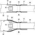
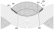
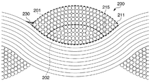
- FIG. 6 is a partial enlarged view showing the Z region of FIG. 1 including the cloth-like member 60, and shows the respective states at the time of gas ejection from the inflator 40 in the order of FIG. 6A and FIG. 6B.
- the airbag device 1 is inserted into the gas inlet 13 of the airbag 10 in a state where the cloth-like member 60 is disposed, and these are put together and clamped and fixed to the outer periphery of the inflator 40 by the clamp 45. In this manner, a plurality of overlapping cloth-like members 60 are installed between the gas ejection port 42 of the inflator 40 and the airbag 10.
- the airbag apparatus 1 receives the gas (refer to the arrow in FIG. 6A) that radiates outward from the plurality of gas ejection ports 42 by the cloth-like member 60, and the opening end of the cloth-like member 60 that inflates with the pressure. Guide toward the side (see arrow in FIG. 6B). As a result, the gas generated by the inflator 40 is rectified and guided toward the inside of the airbag 10 on the outer side in the axial direction, and the gas is supplied into the air chamber 30 of the airbag 10 through them. Therefore, the cloth-like member 60 has a function as a guide member that guides the gas from the inflator 40.
- the cloth-like member 60 receives the high-temperature gas ejected from the gas ejection port 42 to relieve pressure and heat, or prevents the high-temperature gas from directly hitting the airbag 10 and hitting it. It also functions as a protective member for protecting the airbag 10 such as reducing damage to the airbag 10.
- another installation mode of the cloth-like member 60 includes 1 to 5, preferably 1 to 3 cloths, which are formed by cutting into a belt shape having a predetermined shape and size, and the gas ejection port 42. It superimposes on the outer periphery of the inflator 40 so that a part is opened in the airbag along the inflator. With this number of sheets, the airbag 10 can be protected, and the lightweight and excellent storage properties of the airbag apparatus 1 are not impaired.
- the cloth-like member 60 is disposed so as to protrude to a position closer to the rear air chamber 32 than the front end portion of the inflator 40, and a plurality of gas ejection ports are located on the inner side (inner peripheral side), and the whole or a part thereof. Is preferably arranged so as to overlap the inflator 40 so that a part along the open end and the inflator is opened toward the inside of the airbag 10.
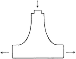
- the cloth-like member shown in FIG. 7 as a cloth-like member called a so-called inner bag or bag-in bag is obtained by sewing or bonding the cloth in advance.
- the aspect to be used is also mentioned.
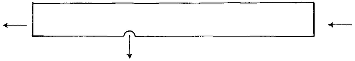
- a mode of using as a cloth-like member called a so-called inner tube that is, a tube-like cloth member shown in FIG. 8 by previously weaving, knitting, or sewing or bonding a flat cloth with a sewing machine. It is done.
- the cloth-like member 60 may use the above-described installation mode alone, but it is also preferable to combine a plurality of installation modes.
- a combination of an installation mode in which a cloth is wound around the outer periphery of the inflator and an inner tube or an inner bag, or a combination of an installation mode in which a cloth is overlapped on the inflator 40 and an inner tube or an inner bag is used to protect the airbag 10 and supply gas to the airbag 10. Smooth guidance to the inflatable and deployable region can be achieved at the same time, which is preferable.
- the cloth to be wrapped or overlapped and the inner tube or the inner bag may be the same material, but the cloth to be wound or overlapped is a cloth containing at least non-melting fibers, and the inner tube or inner bag is made of fibers other than non-melting fibers.
- the combination of is preferable.
- the cloth to be wound, the cloth to be overlapped, the inner tube, and the inner bag may be subjected to any of the above-mentioned flame retardant treatment, flameproof treatment, heat-resistant treatment, and foaming treatment.
- a combination in which any one of the flameproofing treatment and the foaming treatment is applied, and the inner tube or the inner bag is heat-treated is preferable.
- a synthetic resin to which at least a foaming agent is added adheres to the airbag.
- synthetic resin adheres in a specific manner. Specifically, at least 50% or more of the warp / weft crossing surface and the surface layer to the fifth layer of the single yarn constituting the yarn are added to at least a foaming agent. It is preferable that the synthetic resin adhered. With such a specific adhesion mode, the heat resistance of the airbag is remarkably improved not only by foaming of the cloth surface but also by foaming inside the yarn.
- the air permeability at a differential pressure of 100 kPa is 5 cc / cm 2 / sec or less
- the bending resistance measured by the cantilever method is 100 mm or less. If the air permeability at a differential pressure of 100 kPa is 5 cc / cm 2 / sec or less, the maximum internal pressure and the internal pressure maintenance necessary for occupant restraint and manifesting protective performance can be realized in a commonly used curtain airbag. . Further, if the bending resistance measured by the cantilever method is 100 mm or less, the curtain air bag is highly storable because of its flexibility, and there is little risk of damaging the human skin during operation. In the present invention, it is preferable to achieve both low air permeability and high flexibility.
- the amount of resin applied is increased, but in this case, the cloth tends to become hard.
- the resin application amount is reduced to reduce the flexibility, or when the kneading process is performed after the resin application, the air permeability tends to increase, and it is difficult to satisfy both properties.
- the airbag of the present invention needs to be inflated and deployed as soon as possible. Therefore, in order to prevent gas outflow from the base fabric itself, the outer peripheral joint portion, or the inner joint portion, it is important to provide a synthetic resin with a foaming agent added to the base fabric.
- the synthetic resin a known synthetic resin can be used, and is not particularly limited.
- the synthetic resin is composed of an element selected from C, H, N, and O from the viewpoint of good adhesion to the raw yarn and low air permeability. Is preferably used.
- the use of an element selected from C, H, and O is preferable from the viewpoint of safety during combustion.
- synthetic resins include polyurethane resins composed of C, H, N and O and copolymer resins thereof, polyamide resins and copolymer resins thereof, acrylic resins composed of C, H and O, and copolymer resins thereof, Examples thereof include one or more resins selected from the group consisting of polyester resins and copolymer resins thereof, polyvinyl resins and copolymer resins thereof, polyvinyl acetate resins and copolymer resins thereof.
- the resin is selected from the group consisting of an acrylic resin composed of C, H and O and a copolymer resin thereof, a polyester resin and a copolymer resin thereof, a polyvinyl resin and a copolymer resin thereof, a polyvinyl acetate resin and a copolymer resin thereof.
- an acrylic resin composed of C, H and O and a copolymer resin thereof
- a polyester resin and a copolymer resin thereof a polyvinyl resin and a copolymer resin thereof
- a polyvinyl acetate resin and a copolymer resin thereof e.g., ethylene glycol terpolymer resins, polyvinyl acetate resins and their copolymer resins
- each resin examples include polyurethane resins such as “Superflex (registered trademark)” manufactured by Daiichi Kogyo Seiyaku Co., Ltd. and “HYDRAN (registered trademark)” manufactured by Dainippon Ink & Chemicals, Inc. , “Torresin” manufactured by Teikoku Chemical Industry Co., Ltd., as an acrylic resin, “Ultrasol (registered trademark)” manufactured by Gantz Kasei Co., Ltd., "Boncoat (registered trademark)” manufactured by Dainippon Ink & Chemicals, Inc. “Vaironal (registered trademark)” manufactured by Toyobo Co., Ltd.
- the foaming agent for example, a chemical foaming agent or a physical foaming agent can be used.
- the chemical foaming agent include inorganic foaming agents such as sodium hydrogen carbonate, ammonium hydrogen carbonate, and ammonium carbonate, such as organic foaming agents such as nitroso compounds, azo compounds, sulfonyl hydrazide compounds, and carbonamide compounds, and physical foaming agents.
- inorganic foaming agents such as sodium hydrogen carbonate, ammonium hydrogen carbonate, and ammonium carbonate
- organic foaming agents such as nitroso compounds, azo compounds, sulfonyl hydrazide compounds, and carbonamide compounds
- physical foaming agents for example, carbon dioxide gas, nitrogen gas, or the like can be used.
- a chemical foaming agent is preferred because it can be easily added to a synthetic resin.
- an organic foaming agent having high affinity with a synthetic resin and excellent dispersibility and processability is preferable.
- the organic foaming agent preferably contains at least N.
- N-containing organic foaming agent examples include nitroso compounds, azo compounds, sulfonyl hydrazide compounds, and carbonamide compounds.
- nitroso compound examples include N, N′-dinitrosopentamethylenetetramine, and the azo compound is not particularly limited as long as it has at least one —N ⁇ N— group in the molecule.
- the sulfonyl hydrazide compound is a compound having at least one —SO 2 —NHNH 2 group in the molecule, although not particularly limited, for example, 4,4′-oxybis (benzenesulfonylhydrazide), p-toluenesulfonylhydrazide, 2,4-toluenedisulfonylhydrazide, p, p-bis (benzenesulfonylhydrazide) ether, benzene-1, 3-disulfonylhydrazide, benzenesulfoni Hydrazide.
- 4,4′-oxybis benzenesulfonylhydrazide
- p-toluenesulfonylhydrazide 2,4-toluenedisulfonylhydrazide
- p p-bis (benzenesulfonylhydrazide) ether
- benzene-1 3-d
- Examples of the carbonamide compound unit for example, hydrazodicarbonamide the like.
- An azo compound and a sulfonyl hydrazide compound are preferable from the viewpoint of safety, and an azo compound is preferable from the viewpoint of foaming property, and azodicarbonamide having a foaming temperature of 200 ° C. or higher and excellent storage stability is particularly preferable.
- the state in which the foaming agent is added to the synthetic resin is not particularly limited.
- the state in which the foaming agent is dissolved in the synthetic resin, the state in which the foaming agent particles are dispersed in the synthetic resin, and the synthetic resin and the foaming agent are compatible with the sea-island structure. Although the state etc. which were isolate
- the synthetic resin to which the foaming agent is added is preferably used together with a solvent from the viewpoint of excellent processability, and an aqueous synthetic resin using water as a solvent is particularly preferable from the viewpoint that the environmental load caused by the removed solvent is small.
- the aqueous synthetic resin refers to an aqueous solution or aqueous dispersion (aqueous emulsion) of a synthetic resin to which a foaming agent is added.
- aqueous solutions or aqueous dispersions preferably do not contain organic solvents that are often added for the purpose of improving the solubility and dispersibility of the synthetic resin.
- the shrinkage stress of the fibers constituting the base fabric increases at the temperature necessary for removing the organic solvent.
- the pores of the fabric tend to be large, and the air permeability of the base fabric may increase.
- the plasticizer may be any known plasticizer, but is preferably one or more compounds selected from esters, alkylamides, and phosphites.
- one or more compounds selected from esters are preferable because they have good compatibility with the synthetic resin and the foaming agent used in the present invention, and can suppress dispersion after adhesion.
- phosphate esters are preferred.
- ester plasticizer examples include phthalic acid esters, fatty acid esters, polyhydric alcohol esters, phosphoric acid esters, trimellitic acid esters, hydroxybenzoic acid esters, and the like.
- phthalic acid esters include dimethyl phthalate, diethyl phthalate, dibutyl phthalate, diheptyl phthalate, di-2-ethylhexyl phthalate, di-n-octyl phthalate, diisodecyl phthalate, ditridecyl phthalate, and dicyclohexyl phthalate.
- butyl benzyl phthalate diisononyl phthalate, ethyl phthalyl ethyl glycolate, butyl phthalyl butyl glycolate, diundecyl phthalate, and di-2-ethylhexyl tetrahydrophthalate.
- fatty acid esters include dimethyl adipate, dibutyl adipate, diisobutyl adipate, dibutyl diglycol adipate, di-2-ethylhexyl adipate, di-n-octyl adipate, diisodecyl adipate, diisononyl adipate, adipic acid Dibasic saturation such as di-n-mixed alkyl ester, dimethyl sebacate, dibutyl sebacate, di-2-ethylhexyl sebacate, di-2-ethylhexyl azelate, di-2-ethylhexyl mixed acid ester, bis-2-ethylhexyl dodecamate Carboxylic acid esters, dibutyl fumarate, bis-2-methylpropane fumarate, bis-2-ethylhexyl fumarate, dimethyl maleate, diethyl maleate, di
- Group unsaturated carboxylic acid ester include butyl oleate, isobutyl oleate, acetyl butyl ricinoleate, acetyl tributyl citrate, 2-ethylhexyl acetate, and the like.
- polyhydric alcohol esters examples include 2,2,4-trimethyl-1,3-pentadiol monoisobutyrate, 2,2,4-trimethyl-1,3-pentanediol diisobutyrate, diethylene glycol dibenzoate , Triethylene glycol di-2-ethylbutyrate, pentaerythritol monooleate, pentaerythritol monostearate, pentaerythritol trialkyl ester, behenic acid monoglyceride, 2-ethylhexyl triglyceride, glycerin triacetate, glycerin tributyrate, etc. .
- phosphate esters examples include trimethyl phosphate, triethyl phosphate, triphenyl phosphate, tricresyl phosphate, cresyl diphenyl phosphate, tris (t-butylated phenyl) phosphate, tris (i-propyl).
- Phenyl) phosphate 1,3-phenylenebis (diphenylphosphate), 1,3-phenylenebis (dixylenyl) phosphate, bisphenol A bis (diphenylphosphate), (5-ethyl-2-methyl-1, 3,2-dioxaphosphin-5-yl) methyldimethylphosphonate-p-oxide, bis (5-ethyl-2-methyl-1,3,2-dioxaphosphin-5-yl) methylmethyl Phosphonate-p, p'-diochi Id like.
- trimellitic acid esters include tributyl trimellitic acid, tri-2-ethylhexyl trimellitic acid, tri-n-octyl trimellitic acid, triisononyl trimellitic acid, triisodecyl trimellitic acid, and trimellitic acid tri-mixed alcohol ester.
- Hydroxybenzoates include, for example, ethyl hexyl o- or p-hydroxybenzoate, hexyldecyl o- or p-hydroxybenzoate, ethyl decyl o- or p-hydroxybenzoate, methyl o- or p-hydroxybenzoate.
- Examples include dodecyl acid and the like.
- alkylamides include toluenesulfonic acid alkylamides and benzenesulfonic acid alkylamides.
- toluenesulfonic acid alkylamides include N-ethyl-o-toluenesulfonic acid butyramide, N-ethyl-p-toluenesulfonic acid butyramide, N-ethyl-o-toluenesulfonic acid 2-ethylhexylamide, and N-ethyl.
- -P-toluenesulfonic acid 2-ethylhexylamide and the like are exemplified.
- benzenesulfonic acid alkylamides examples include benzenesulfonic acid propylamide, benzenesulfonic acid butyramide, and benzenesulfonic acid 2-ethylhexylamide.
- phosphites examples include alkyl phosphites such as trisisodecyl phosphite and trilauryl phosphite, aryl phosphites such as triphenyl phosphite and tris (nonylphenyl) phosphite, diphenylisooctyl phosphite, and diphenylisophosphite.
- Decyl phosphite diisodecyl phenyl phosphite, diisooctyl octyl phenyl phosphite, phenyl neopentyl glycol phosphite, 2,4,6-tri-t-butylphenyl- (2-butyl-2-ethyl-1,3- Examples thereof include alkyl-aryl phosphites such as propanediol) phosphite.
- the plasticizers exemplified above may be used alone or in combination of two or more.
- the addition amount of the plasticizer is 1 to 40 parts by weight, preferably 3 to 30 parts by weight, based on 100 parts by weight of the synthetic resin to which the foaming agent is added.
- the water-based synthetic resin may be used by mixing additives such as a deterioration inhibitor, a crosslinking agent, an inorganic filler, a colorant, a flame retardant, etc. within a range that does not affect the target performance in the present invention.
- additives such as a deterioration inhibitor, a crosslinking agent, an inorganic filler, a colorant, a flame retardant, etc.
- a means for applying a synthetic resin in which a foaming agent is added to the cloth is not particularly specified, and a known means can be used.
- a known means can be used.
- means for applying an aqueous synthetic resin to a cloth, impregnating the aqueous synthetic resin with the cloth, or spraying the aqueous synthetic resin onto the cloth is disclosed. Since the equipment is simple and excellent in workability, means by impregnation that can be carried out at low cost is preferable. In particular, a means of impregnating the water-based synthetic resin after impregnating the cloth with water is preferable.
- FIG. 12 is an enlarged cross-sectional view of a curtain airbag base fabric obtained by the present invention.
- the warp / weft crossing portion 200 is shown, and the warp and the weft are shown crossing each other.
- Each of the warp and the weft is composed of a number of single yarns.
- Synthetic resin is adhered from the surface layers of the warp and weft yarns to the single yarn located in several layers (201 in FIG. 12). However, since it is impregnated with water, the synthetic resin is prevented from adhering to the single yarn of a deeper layer as shown by 202 in FIG.
- the synthetic resin is adhered between the warp yarns or the weft single yarns of the surface layer 211 to the fifth layer 215 of the raw yarn, and the gap is filled at least at one place between the warp yarns or the weft yarns.
- the method of filling the gap is not particularly limited, but an embodiment in which the synthetic resin adheres and fills the gap over a length of 10% or more, particularly 30% or more of the diameter of the single yarn cross section is preferable. Further, when the length of the cross section of the base fabric is observed to be 20 mm, 50% or more, preferably 70% or more, particularly preferably, of the 201 parts in the warp / weft crossing part 200 existing therein. More than 80%, the synthetic resin adheres to the gap between the warp and the weft of three or more single yarns of either the warp or the weft, such as 220 or 221 where the warp and the weft contact, It is preferable to fill the gap.
- the method of filling the gap is not particularly limited, but an embodiment in which the synthetic resin adheres and fills the gap over a length of 10% or more, particularly 30% or more of the diameter of the single yarn cross section is preferable.
- the synthetic resin is contained in 50% or more, preferably 70% or more, particularly preferably 80% or more of the recesses between the warp and weft single yarns of the surface layer 201 of the original yarn. It is preferable that adheres and covers the recess.
- the thickness equivalent to the diameter for one warp or the weft is more than the thickness equivalent to the diameter for five.
- the water impregnation rate when impregnating with water is preferably 3 to 50% by weight, particularly 5 to 30% by weight. If it is this range, the effect described above can be obtained, and synthetic resin can be imparted with a sufficiently low air permeability.
- the means for controlling the water impregnation rate is not particularly specified, but for example, means for impregnating water and then squeezing with a mangle adjusted to an appropriate pressure, means for impregnating water and then sucking water by decompression, impregnating water Then, a means for drying to a predetermined amount by air drying, a drier or the like is exemplified.
- the concentration of the synthetic resin to which the foaming agent is added in the water-based synthetic resin is not particularly limited, but is preferably 0.05 to 60% by weight, particularly 1 to 50% by weight. If it is this density
- the solvent drying temperature carried out after the application of the water-based synthetic resin is not particularly limited as long as it does not impair the properties of the base fabric and the added foaming agent does not foam, but it is preferably 50 to 220 ° C., for example, 100 to 200 More preferably, the temperature is set to ° C.
- the adhesion rate of the synthetic resin to which the foaming agent is added is preferably 0.1 to 20% by weight, more preferably 1 to 12% by weight, and particularly preferably 5 to 10% by weight. If the adhesion rate of the synthetic resin to which the foaming agent is added is within this range, sufficient low air permeability can be secured, and excellent storage properties can be maintained without impairing the flexibility of the base fabric. The possibility of damaging the human skin on the cloth surface can be reduced, and the foaming agent foams with high-temperature gas, and the heat resistance of the airbag is reduced by the formation of a protective structure and mixing with the foaming gas, thereby reducing the gas temperature. Improved and preferred.
- the weight ratio of the synthetic resin attached to the base fabric and the foaming agent is 99: 1 to 60:40, particularly 97: 3 to 80:20. In particular, 97: 3 to 90:10 is preferable.
- the airbag of the present invention uses an airbag cloth to which a synthetic resin added with at least a foaming agent is attached, cuts the component parts according to the required shape, and sews and / or bonds these component parts. Can be manufactured.
- the sewing method, sewing thread, bonding method and adhesive are not particularly limited, and conventionally known methods and materials may be employed.
- a known sealing means such as a sealing tape
- at least a foaming agent was added to an airbag base fabric woven by the OPW method in which weaving yarns were crossed into a predetermined position and shape at the weaving stage to form a joint.
- An airbag to which a synthetic resin is attached is also included.
- the heating temperature is preferably 180 ° C. or higher and 250 ° C. or lower.
- the applied pressure is preferably 200 N / mm or more and 500 N / mm or less.
- a cloth-like member that surrounds the gas ejection port of the inflator and opens into the airbag.
- a cloth-like member a known cloth-like article such as a woven fabric, a knitted fabric, or a non-woven fabric can be used, but a woven fabric excellent in high-temperature gas barrier properties is preferable.
- the structure of the woven fabric is not particularly limited, and a known structure can be used. In particular, it is preferable to use a cloth-like member containing at least non-molten fibers.
- the non-melting fiber means a fiber in which a clear endothermic peak accompanying melting is not observed in heat measurement by DSC (differential scanning calorimetry).
- DSC differential scanning calorimetry
- the non-melt fiber include, but are not limited to, cellulosic fibers, acrylic fibers, aramid fibers, vinylon fibers, carbon fibers, ceramic fibers, and animal natural fibers.
- the cloth-like member preferably contains at least one of cellulose fiber, acrylic fiber, aramid fiber, vinylon fiber, carbon fiber, ceramic fiber, and animal natural fiber. Cellulosic fibers, acrylic fibers, and animal natural fibers are particularly preferable in view of good handling properties such as safety and low cost. It is also preferable to mix two or more types of non-melt fibers.
- Cellulosic fibers are fibers mainly composed of cellulose, and examples thereof include natural fibers such as cotton, hemp, and jute, and regenerated fibers such as rayon, lyocell, and cupra.
- An acrylic fiber is a fiber containing 35% or more of acrylonitrile or an acrylate fiber obtained by chemically modifying the fiber.
- An aramid fiber is an aromatic amide fiber and includes a para-aramid fiber and a meta-aramid fiber, and a meta-aramid fiber having excellent heat resistance is preferred. Examples of para-aramid fibers include polyparaphenylene terephthalamide, and examples of meta-aramid fibers include polymetaphenylene terephthalamide.
- Vinylon fiber is a general term for fibers obtained by acetalizing polyvinyl alcohol.
- Carbon fiber is a fiber made by carbonizing acrylic fiber or pitch (by-products such as petroleum, coal, coal tar, etc.) as a raw material at a high temperature, and graphite at an ultra-high temperature of 2,000 ° C. or higher in an inert atmosphere.
- Graphitized fibers are also included.
- the ceramic fiber is a fiber made from a ceramic such as alumina or silicon carbide, and examples thereof include alumina fiber and silicon carbide fiber.
- Animal natural fibers are natural fibers derived from animals, such as animal hair (wool, alpaca, cashmere, etc.), silk, and the like.
- the non-melting fiber may be used alone, but may be mixed with fibers other than the non-melting fiber.
- the fibers other than the non-melted fibers are not particularly limited, but when the synthetic fibers to be melted are melted by the high-temperature gas, they absorb heat to suppress heat conduction from the high-temperature gas to the airbag. ,preferable. If fibers other than non-molten fibers are used alone, heat conduction is suppressed, but the cloth-like member may be damaged by melting and may not exhibit sufficient airbag protection performance. Thus, damage to the cloth-like member can be suppressed while taking advantage of suppressing heat conduction.
- a synthetic fiber such as polyamide or polyester is preferable from the viewpoint of increasing the strength of the cloth member.
- the form of mixing non-melted fibers and fibers other than non-melted fibers is not particularly limited, and known forms can be used.
- stacking the cloth which consists it does not specifically limit.
- a cloth made of fibers other than unmelted fibers is used on the gas outlet side of the inflator.
- a mixed form in which a cloth made of non-melting fibers is disposed is preferable.
- the form of the non-melted fiber is not particularly limited and can be used in a known form, but it is preferable to use a short fiber having a large gap between yarns and a high effect of suppressing heat conduction.
- the form of fibers other than the non-melted fiber is not particularly limited, and can be appropriately used in a known form depending on the purpose of use. That is, short fibers are preferably used when importance is placed on the performance of suppressing the heat conduction of the cloth-like member, and long fibers are preferably used when importance is placed on increasing the strength of the cloth-like member.
- the combination of the form of the non-melt fiber and the form of the fiber other than the non-melt fiber is not particularly limited, but the non-melt fiber is a short fiber from the viewpoint of achieving both the effect of suppressing the heat conduction of the cloth-like member and the effect of improving the strength.
- a combination in which fibers other than non-melting fibers are long fibers is preferable.
- the cloth-like member of the present invention is preferably subjected to at least one of a flame retardant treatment, a flameproof treatment, a heat-resistant treatment, and a foaming treatment because damage to the cloth-like member due to high-temperature gas is reduced.
- the flame retardant treatment, the flame proof treatment, the heat resistance treatment, and the foaming treatment may be performed on at least one surface of the cloth member. It is preferable that the surface of the cloth-like member on the gas ejection port side of the inflator is subjected to any one of flame retardant treatment, flameproof treatment, heat resistance treatment, and foaming treatment.
- Flame retardant treatment is a treatment that makes a cloth-like member difficult to burn
- flameproof treatment is a treatment that makes it difficult to spread even if a flame is applied.
- the flame retardant treatment is performed by applying a liquid in which a flame retardant is dissolved or dispersed to the surface of the cloth-like member by a known method such as a padding method, a spray method, or a coating method.
- the flame retardant is not particularly limited, and a known flame retardant can be used.
- Brominated flame retardants aromatic phosphates such as triphenyl phosphate, phosphorus flame retardants such as red phosphorus, chlorinated flame retardants such as chlorinated paraffin, metal hydroxides such as aluminum hydroxide and magnesium hydroxide
- flame retardants include antimony flame retardants such as antimony pentoxide.
- aromatic phosphate esters such as triphenyl phosphate, phosphorus flame retardants such as red phosphorus, and metal hydroxide flame retardants such as aluminum hydroxide and magnesium hydroxide are preferred.
- An aromatic phosphate such as triphenyl phosphate and a phosphorus flame retardant such as red phosphorus are preferred.
- the flameproofing treatment is performed by applying a liquid in which a flameproofing agent is dissolved or dispersed to the surface of the cloth-like member by a known method such as a padding method, a spray method, or a coating method.
- the flameproofing agent is not particularly limited, and a known flameproofing agent can be used.
- aromatic condensed phosphate ester, phosphate ester amide, guanidine phosphate derivative, halogen-containing organic phosphorus compound, guanyl Examples include sulfamide and hexabromocyclododecane.
- Aromatic condensed phosphate esters, phosphate ester amides, and phosphate guanidine derivatives that have a high effect of imparting flameproofing properties to many types of non-melt fibers are preferred.
- the heat resistance treatment is a treatment for improving the heat resistance by providing a heat resistant layer on the surface of the cloth-like member.
- the heat-resistant layer is not particularly limited as long as it improves the heat resistance of the cloth-like member, but examples thereof include heat-resistant resins, rubbers, metal thin films, and metal oxide thin films.
- the heat-resistant resin and rubber include silicone resin or rubber, fluororesin or rubber
- examples of the metal thin film include aluminum thin film, nickel thin film, copper thin film, silver thin film, and gold thin film.
- the metal oxide thin film include an alumina thin film and a titanium oxide thin film.
- a known method can be used as a method for providing the heat-resistant layer, and is not particularly limited.
- examples thereof include a coating method, a laminating method, a padding method, and a spray method.
- a vapor deposition method, a sputtering method, an electroless plating method, and the like are exemplified, and if it is a metal oxide, a vapor deposition method, a sputtering method, and the like are exemplified.
- the foaming treatment is to protect the surface of the cloth-like member by applying a foaming agent to the surface of the cloth-like member and generating a gas from the foaming agent when the cloth-like member comes into contact with a high-temperature gas.
- a foaming agent for example, a chemical foaming agent or a physical foaming agent can be used.
- a chemical foaming agent is preferred because it can be easily added to a synthetic resin.
- the chemical foaming agent include inorganic foaming agents such as sodium hydrogen carbonate, ammonium hydrogen carbonate, and ammonium carbonate, such as organic foaming agents such as nitroso compounds, azo compounds, sulfonyl hydrazide compounds, and carbonamide compounds, and physical foaming.
- a chemical foaming agent is preferred because it can be easily added to a synthetic resin.
- an organic foaming agent having high affinity with a synthetic resin and excellent dispersibility and processability is preferable.
- the organic foaming agent preferably contains at least N.
- the N-containing organic foaming agent include nitroso compounds, azo compounds, sulfonyl hydrazide compounds, and carbonamide compounds.
- the nitroso compound include N, N′-dinitrosopentamethylenetetramine, and the azo compound is not particularly limited as long as it has at least one —N ⁇ N— group in the molecule.
- the sulfonyl hydrazide compound is a compound having at least one —SO 2 —NHNH 2 group in the molecule, although not particularly limited, for example, 4,4′-oxybis (benzenesulfonylhydrazide), p-toluenesulfonylhydrazide, 2,4-toluenedisulfonylhydrazide, p, p-bis (benzenesulfonylhydrazide) ether, benzene-1, 3-disulfonylhydrazide, benzenesulfoni Hydrazide.
- 4,4′-oxybis benzenesulfonylhydrazide
- p-toluenesulfonylhydrazide 2,4-toluenedisulfonylhydrazide
- p p-bis (benzenesulfonylhydrazide) ether
- benzene-1 3-d
- Examples of the carbonamide compound include hydrazodicarbonamide the like.
- An azo compound and a sulfonyl hydrazide compound are preferable from the viewpoint of safety, and an azo compound is preferable from the viewpoint of foaming property, and azodicarbonamide having a foaming temperature of 200 ° C. or higher and excellent storage stability is particularly preferable.
- the method for manufacturing the airbag 10 can be a known method and is not particularly limited.
- the manufacturing method in the case of providing resin which added the foaming agent is illustrated, it is not limited to this manufacturing method.
- the warp yarn is usually woven using sized raw yarn, and then a step of attaching a synthetic resin to which a foaming agent is added is applied in order to improve the airtightness of the airbag.
- the oils attached to the raw yarn prior to the step of attaching the synthetic resin added with the foaming agent so as not to inhibit the adhesion between the synthetic resin added with the foaming agent and the fabric
- After scouring it is preferable to attach a synthetic resin to which a foaming agent is added to the woven fabric, and to dry and heat set in order to control the dimensions and the weave density.
- the sewing machine method and the bonding method are not particularly limited in carrying out the present invention, but when weaving without sizing warp, scouring is not necessarily required, but when using sizing yarn, etc.
- scouring is not necessarily required, but when using sizing yarn, etc.
- the airbag device of the present invention is obtained.
- a base fabric to which a synthetic resin is attached is cut into a predetermined shape and size, and then two fabrics are overlapped to sew a predetermined position.
- a sealant such as a silicone sheet is sandwiched between two cloths and sewn.
- the base fabric to which the synthetic resin is attached is cut into a predetermined shape and size, and then the two fabrics are stacked and bonded at a predetermined position.
- a sealing agent such as a silicone sheet is sandwiched between the two cloths and bonded together.
- Air permeability measuring device The test sample was measured with a TEXTEST company air bag dedicated air permeability tester (FX3350). The test head was set to 400 cc and the start pressure was set to 170 kPa. From the results after the test, the air permeability at the time of 100 kPa differential pressure was read, and when there are a plurality of air permeability data at the time of 100 kPa differential pressure, the average value was obtained and used as the air permeability at the time of 100 kPa differential pressure.
- FX3350 TEXTEST company air bag dedicated air permeability tester
- Examples 1 to 3 Made by Asahi Kasei Fiber Co., Ltd., nylon 66 raw yarn fineness 470dTex, single yarn number 72 yarns, sizing with sizing agent mainly composed of polyacrylic acid, and equipped with jacquard machine (made by Stoveley)
- the woven fabric having the shape shown in FIG. 1 was woven using an air jet loom (manufactured by Dornier) so that the finished weaving density was 57 warps / 2.54 cm and 48 wefts / 2.54 cm.
- the inflated part is a plain weave structure, the weave structure of each inner joint near the boundary with the inflated part is the structure shown in FIG. 8, and the inner woven structure near the boundary with the inflated part of each inner joint is shown in FIG. The organization shown.
- the woven fabric after weaving was scoured with a continuous scourer, dried and then heat set at 180 ° C. for 1 minute with a pin tenter.
- the fabric after the scouring and heat setting was impregnated with water, then squeezed with a mangle, and then naturally dried to obtain a base fabric having a water adhesion rate of 10% by weight.
- the ratio of the ethylene-vinyl acetate copolymer (“RD-321” manufactured by Kyoyo Chemical Industry Co., Ltd.) and the foaming agent A: azodicarbonamide (“Cermic C-2” manufactured by Sankyo Kasei Co., Ltd.) was 98: 2 (Example 1). ), 90:10 (Example 2), and 80:20 (Example 3), a synthetic resin added with a foaming agent is used as an aqueous dispersion with a solid content concentration of 30% by weight, and the base fabric is impregnated. Thereafter, the fabric was dried to obtain a curtain bag cloth having a synthetic resin adhesion rate of 8 wt% to which a foaming agent was added.
- This cloth was cut into a predetermined shape by a laser cutting machine (manufactured by Lectra).
- two pieces of cotton cloth (100 mm thick, flame protection time 3.6 seconds) woven with a wig structure using 100% cotton No. 7 single cotton yarn, cut into a width of 100 mm and a length of 60 mm, Gas blowout port of the inflator so that the coated surface is on the inflator side, one piece of silicon nylon coated (0.7mm thick, flame protection time 9.8 seconds) cut to the same size was covered with a nylon cloth on the inflator side, and then fixed with a clamp with an airbag. Reinforced stitching of the attachment part to the car body and sewing of the front strap were performed to make an airbag product. Further, the product was folded by the method shown in FIG. 10 and temporarily fixed with a tape to prepare a test sample. A predetermined test was performed on this sample.
- Example 2 the synthetic resin to which the foaming agent was added was used as an aqueous dispersion having a solid content of 40% by weight, the synthetic resin adhesion rate to which the foaming agent was added was 12% by weight (Example 4), and the foaming agent was added.
- An airbag was manufactured in the same manner except that the synthetic resin was an aqueous dispersion having a solid content concentration of 10% by weight, and the synthetic resin adhesion rate to which the foaming agent was added was 4% by weight (Example 5). Carried out.
- Example 6 In Example 2, (5-ethyl-2-methyl-1,3,2-dioxaphosphin-5-yl) methyldimethylphosphonate as a plasticizer was added to 100 parts by weight of a synthetic resin to which a foaming agent was added. An airbag was manufactured in the same manner except that 20 parts by weight of p-oxide was mixed and used, and a predetermined test was performed.
- Example 7 In Example 2, an airbag was manufactured in the same manner except that a yarn having a fineness of 470 dTex of nylon 66 yarn and 144 single yarns manufactured by Asahi Kasei Fibers Co., Ltd. was used, and a predetermined test was performed.
- Example 8 In Example 2, an airbag was manufactured in the same manner except that foaming agent B: hydrazodicarbonamide (“Cermic 142” manufactured by Sankyo Kasei Co., Ltd.) was used, and a predetermined test was performed.
- foaming agent B hydrazodicarbonamide (“Cermic 142” manufactured by Sankyo Kasei Co., Ltd.) was used, and a predetermined test was performed.
- Example 9 The heat setting was performed in the same manner as in Example 2, and then an ethylene-vinyl acetate copolymer (“RD-321” manufactured by Kyoyo Chemical Industry Co., Ltd.) was impregnated as an aqueous dispersion having a solid content concentration of 30% by weight. Then, an airbag was manufactured in the same manner except that it was dried to obtain an airbag fabric, and a predetermined test was performed.
- RD-321 manufactured by Kyoyo Chemical Industry Co., Ltd.
- Example 10 In Example 1, the woven fabric after weaving was scoured with a continuous scourer, dried and then heat set at 180 ° C. for 1 minute with a pin tenter. The fabric after the scouring and heat setting by a knife coating method, a silicon resin (Dow Corning Toray Silicone Co., Ltd., product number DC3730) one side per 35 g / m 2 was coated fabric, 180 ° C. 3 minutes in a heating furnace An airbag was manufactured in the same manner except that the cloth for curtain airbag was obtained by heating, and a predetermined test was performed.
- a silicon resin Dow Corning Toray Silicone Co., Ltd., product number DC3730
- Example 11 to 20 Examples 1 to 10 except that, as a cloth-like member, a single yarn No. 7 blended with 65% cotton and 35% polyethylene terephthalate was used, and three blended fabrics woven with a katsura texture were used in an overlapping manner. Similarly, an airbag was manufactured and a predetermined test was performed. The blended cloth had a thickness of 0.7 mm and a flame protection time of 6.9 seconds.
- Example 21 In Example 1, an airbag was manufactured in the same manner except that the cloth-like member was overlapped with three pieces of cotton (Example 21) and the cloth-like member was overlapped with two pieces of nylon cloth (Example 22). A predetermined test was conducted.
- Example 23 and 24 Flame-retardant cotton coated with 70 g / m 2 of an ethylene-vinyl acetate copolymer (“RD-321” manufactured by Kyoyo Chemical Co., Ltd.) containing 50% by weight of aluminum hydroxide as a flame retardant on one side of cotton (thickness 0) .5 mm, flame protection time 3.8 seconds) 3 sheets were used as a cloth-like member (Example 23), and ethylene-vinyl acetate copolymer (“RD-321” manufactured by Kyoyo Chemical Co., Ltd.) And a foaming agent A: azodicarbonamide (“Cermic C-2” manufactured by Sankyo Kasei Co., Ltd.) at a ratio of 90:10, and a synthetic resin added with the foaming agent is used as an aqueous dispersion having a solid content of 30% by weight.
- RD-321 ethylene-vinyl acetate copolymer
- RD-321 ethylene-vinyl acetate
- Example 24 In the same manner as in Example 1, except that a superposition of three sheets of foam-treated cotton impregnated in cotton (thickness 0.5 mm, flame protection time 4.5 seconds) was used as a cloth-like member (Example 24). Make a bag and conduct a predetermined test did.
- Example 25 Silicone resin is coated on one side, a dry nylon cloth (thickness 0.4 mm, flame protection time 3.3 seconds) is used, and the inner surface of the shape shown in FIG. An airbag was manufactured in the same manner as in Example 1 except that it was used as a cloth-like member, and a predetermined test was performed.
- Example 3 An airbag is manufactured in the same manner as in Example 9 (Comparative Example 3) and in the same manner as in Example 10 (Comparative Example 4) except that three nylon cloths are used as the cloth-like member. The test was conducted.
- the airbag device according to the present invention does not rupture even when deployed at room temperature and high temperature, and the deployment speed is sufficiently fast, which is effective in improving the occupant protection performance. It is clear. In particular, rupture does not occur even when deployed at high temperatures, which is a severe condition for airbags, and sufficient occupant protection performance can be achieved. In addition, since a lightweight and flexible cloth-like member is used and a metal guide tube is not required, it is possible to obtain a lightweight and highly packable airbag device, which is required for automobiles. It is possible to realize an airbag device that can cope with the above.
- the present invention is effective for a device for protecting a vehicle occupant when a vehicle, particularly an automobile, collides.
- it is effective for an airbag device that is lightweight, small and excellent in storability, and also excellent in performance for ensuring the safety of passengers.
- Airbag apparatus Airbag 11 Upper attachment tab 12 Front part attachment piece 13 Gas inlet 20 Front side cloth 21 Back side cloth 22 Outer peripheral junction part 23, 24, 25, 26 Inner junction part 30 Air chamber 31 Front air chamber 32 Rear part Air chamber 40 Inflator 42 Gas outlet 45 Clamp 60 Cloth member 200 Warp / weft crossing portion 201 Portion where synthetic resin adheres 202 Portion where synthetic resin does not adhere 211 Single yarn of surface layer 215 5th layer Single yarn 220, 221 Portion where synthetic resin adheres to the contact point of warp and weft 230 Concavity where synthetic resin adheres
Abstract
Disclosed is an airbag device that achieves reduced weight and efficiently avoids airbag breakage from high-temperature gas from an inflator, offering superior protective functionality. The airbag device comprises a fabric-like member, including at least a non-melting fiber, which surrounds an inflator gas discharge port so as to open into the airbag. Alternatively, a plastic, whereto is added at least a foaming agent, is attached to the airbag.
Description
本発明は、自動車等の車両に搭載され、インフレーターから供給されるガスによりエアバッグを膨張展開させて乗員を保護するエアバッグ装置、特にインフレーターから供給されるガスによるエアバッグの損傷を効率的に防止し、より確実に乗員を保護することを可能とし、かつ軽量で収納性に優れたエアバッグ装置に関する。
The present invention is an airbag device that is mounted on a vehicle such as an automobile and inflates and deploys an airbag with gas supplied from an inflator to protect an occupant, and in particular, efficiently damages the airbag due to gas supplied from the inflator. The present invention relates to an airbag device that is capable of preventing and protecting an occupant more reliably, and that is lightweight and excellent in storage.
自動車等の車両の衝突時や緊急時等に運転席や助手席の乗員等を保護するため、例えばステアリングホイールやインストルメントパネル部に、膨張展開可能なエアバッグを備えたエアバッグ装置を搭載した自動車が広く普及している。自動車の前面が他の自動車や障害物と衝突(正面衝突)した際に、乗員と自動車車内構造物との間に急速に袋体を膨張させて乗員の安全を図ることが可能となる。
In order to protect occupants in the driver's seat and front passenger seat in the event of a vehicle collision such as an automobile or an emergency, an airbag device equipped with an airbag that can be inflated and deployed is mounted on the steering wheel or instrument panel, for example. Automobiles are widely used. When the front of the automobile collides with another automobile or an obstacle (frontal collision), it is possible to rapidly inflate the bag body between the occupant and the vehicle interior structure to ensure the safety of the occupant.
近年この正面衝突だけでなく、自動車の側面が他の自動車や障害物と衝突(側面衝突)した際に乗員の頭部などを保護するために、自動車の側面窓部上の天井部やピラー部に折り畳んで収納されているカーテンエアバッグが衝突時に側面窓部を覆うように膨張するカーテンエアバッグ装置が本格的に搭載され始めている。
Not only this frontal collision in recent years, but also the ceiling part and pillar part on the side window part of the car to protect the occupant's head etc. when the side of the car collides with other cars and obstacles (side collision) A curtain airbag device that is inflated so as to cover a side window portion at the time of a collision when the curtain airbag stored in a folded state is being installed in earnest.
このようなエアバッグ装置の一例として、特許文献1に示されるものが知られている。この特許文献1に記載されたエアバッグ装置は、車両側部のルーフレール部等にエアバッグを取り付け、インフレーターからのガスにより、車内側の開口を塞いで車壁を覆うようにエアバッグを膨張展開させ、前後席の乗員の主に頭部を保護する。また、このエアバッグ装置では、シリンダタイプのインフレーターを使用し、その円筒状の本体部外周に金属製の案内筒(案内筒部)を固定して一端部の複数のガス噴出し口を囲い、案内筒の先端開口部をエアバッグ内に挿入して、エアバッグのガス導入口にインフレーターを取り付けている。エアバッグ装置は、この案内筒により、ガス噴出し口から例えば放射状に噴き出すガスをエアバッグ内のインナーチューブに案内し、それらを介してエアバッグ内にガスを供給してエアバッグを膨張展開させる。この金属製の案内筒はインフレーターのガス噴出し口から噴き出すガスの圧力を緩和し、或いは、ガスが基布に直接噴射されて当たるのを防止して、エアバッグを保護するための機能も有する。
As an example of such an airbag device, one disclosed in Patent Document 1 is known. The airbag device described in Patent Document 1 is provided with an airbag attached to a roof rail portion or the like on the side of the vehicle, and the airbag is inflated and deployed so as to cover the vehicle wall by closing the opening inside the vehicle with the gas from the inflator. And protect the head mainly for the front and rear passengers. Further, in this airbag device, a cylinder type inflator is used, a metal guide tube (guide tube portion) is fixed to the outer periphery of the cylindrical main body portion, and a plurality of gas ejection ports at one end portion are enclosed, The tip opening of the guide tube is inserted into the airbag, and an inflator is attached to the gas inlet of the airbag. The airbag device guides, for example, a gas ejected radially from the gas ejection port to the inner tube in the airbag, and supplies the gas into the airbag through them to inflate and deploy the airbag. . This metal guide tube also has a function to protect the airbag by relieving the pressure of the gas ejected from the gas ejection port of the inflator or preventing the gas from being directly injected to the base fabric. .
また、特許文献2には、ガスの導入により車壁を覆うように膨張展開可能なエアバッグと、複数のガス噴出し口から放射状にガスを噴出しエアバッグ内に供給するインフレーターとを備え、エアバッグが、インフレーターが取り付けられたガス導入口と、このガス導入口からのガスにより膨張する気室とを有するエアバッグ装置であって、複数のガス噴出し口を囲い、エアバッグ内に向かって開口するようにインフレーターに複数回巻回された布状部材を備えるエアバッグ装置が開示されている。エアバッグ装置のインフレーターに重たい金属製の案内筒を設けることなく、軽量で柔軟な布状部材を設けることでガス噴出し口から供給されるガスを案内でき、かつ、そのガスからエアバッグを保護することができる。
Patent Document 2 includes an airbag that can be inflated and deployed so as to cover a vehicle wall by introducing gas, and an inflator that ejects gas radially from a plurality of gas ejection ports and supplies the gas into the airbag. An airbag is an airbag device having a gas inlet port to which an inflator is attached and an air chamber that is inflated by gas from the gas inlet port, and surrounds the plurality of gas ejection ports and faces into the airbag. An airbag device is disclosed that includes a cloth-like member wound around an inflator a plurality of times so as to open. Without providing a heavy metal guide tube on the inflator of the airbag device, a lightweight and flexible cloth-like member can be used to guide the gas supplied from the gas outlet and protect the airbag from the gas. can do.
ところで、車両では、燃費効率を向上させるために軽量化を図ることが必要であり、全ての部材において、軽量化が必須となっている。エアバッグ装置においても軽量化を図る取り組みがなされており、その一つとして、インフレーターを小型軽量化することが考えられている。小型軽量なインフレーターで従来と同様の膨張展開に必要な体積のガスを発生させるためには、ガス温度を上昇させることが必要であり、インフレーターの小型軽量化に伴い、エアバッグへの熱的負荷は増加する傾向にある。さらに高温環境下、例えば、80℃でもエアバッグが機能することが要求されており、過酷な環境により、熱的負荷が一層増加する。熱的負荷によるエアバッグの損傷を防止するために、特許文献1に開示されているように、金属製の案内筒を用いることが検討されているが、金属製の案内筒はエアバッグの保護性能は高いが、重量が大きいために、エアバッグ装置の軽量化要求には反する。また、金属製の案内筒をインフレーターの外周にかしめて固定する必要があるため、インフレーターへの取り付けの手間が増加する傾向にある。
By the way, in the vehicle, it is necessary to reduce the weight in order to improve the fuel efficiency, and the weight reduction is indispensable for all the members. In air bag devices, efforts are being made to reduce the weight, and as one of them, it is considered to reduce the size and weight of the inflator. In order to generate the volume of gas necessary for inflation and deployment in a small and lightweight inflator, it is necessary to raise the gas temperature, and as the inflator becomes smaller and lighter, the thermal load on the airbag Tend to increase. Furthermore, the airbag is required to function even in a high temperature environment, for example, at 80 ° C., and the thermal load is further increased due to the severe environment. In order to prevent damage to the airbag due to a thermal load, as disclosed in Patent Document 1, it has been studied to use a metal guide tube, but the metal guide tube protects the airbag. Although the performance is high, the weight is large, which is contrary to the demand for weight reduction of the airbag device. Moreover, since it is necessary to caulk and fix the metal guide tube on the outer periphery of the inflator, there is a tendency for the labor required for attachment to the inflator to increase.
一方、特許文献2に開示されている布状部材を用いることは、金属製の案内筒が有する前記問題点を解決するために有効であるが、エアバッグの保護性能が十分ではない場合がある。殊に、固体のガス発生剤を使用するパイロタイプインフレータや高圧ガスと固体ガス発生剤を併用するハイブリッドタイプインフレータを高温環境下で使用する場合は、インフレーターからのガスが極めて高温であるため、エアバッグを保護するには、布状部材を何重にも重ねる等多量の布状部材を用いる必要が生じ、十分な軽量化が達成できない可能性があり、さらに嵩高く収納性が悪くなる場合も起こりえる。
On the other hand, using the cloth-like member disclosed in Patent Document 2 is effective for solving the above-described problems of the metal guide tube, but the protection performance of the airbag may not be sufficient. . In particular, when a pyro type inflator that uses a solid gas generating agent or a hybrid type inflator that uses a combination of a high pressure gas and a solid gas generating agent is used in a high temperature environment, the air from the inflator is extremely hot. In order to protect the bag, it is necessary to use a large amount of cloth-like members such as multiple layers of cloth-like members, and there is a possibility that sufficient weight reduction may not be achieved. It can happen.
さらに、金属製の案内筒や布状部材を用いても、高温のガスがエアバッグに接触する場合があり、エアバッグを構成する素材が熱的ダメージを受け、乗員を保護するに十分な膨張展開ができない可能性がある。殊に高温環境下で使用することを想定した場合、素材が熱的ダメージを受ける可能性が高まる。熱的ダメージを軽減するために、エアバッグにはクロロプレン、クロロスフォン化オレフィン、シリコーンなどの合成ゴムを被覆したコーティング基布が、耐熱性や空気遮断性(低通気性)、難燃性といった特性に優れることから使用されているが、合成ゴムをコーティングした基布は、基布重量が増大し、また柔軟性が満足できるものでなく、製造コストも高いため、エアバッグ用基布として使用するには不十分な点が多かった。
Furthermore, even if a metal guide tube or cloth-like member is used, high-temperature gas may come into contact with the airbag, so that the material constituting the airbag is thermally damaged and is sufficiently expanded to protect the occupant. Deployment may not be possible. In particular, when it is assumed that the material is used in a high temperature environment, the possibility that the material is thermally damaged increases. In order to reduce thermal damage, the coating base fabric coated with synthetic rubber such as chloroprene, chlorosulfonated olefin, silicone, etc. is used for the air bag, such as heat resistance, air barrier (low breathability), flame resistance, etc. Although it is used because of its excellent characteristics, the base fabric coated with synthetic rubber is used as a base fabric for airbags because the weight of the base fabric increases, the flexibility is not satisfactory, and the manufacturing cost is high. There were a lot of things that weren't enough.
本発明は、エアバッグ装置において、エアバッグの耐熱性を高め、軽量・小型で高温ガスを噴出するインフレーターを高温環境下で用いても、乗員を保護するに十分な膨張展開が可能とするとともに、軽量な布状部材を用いて、エアバッグ装置の軽量化を達成し、エアバッグを保護する性能を効率的に高めるようにすること、また、エアバッグ装置の構造を簡単にして、嵩高く収納性が悪化することを抑制することを目的とする。
In the airbag device, the present invention can increase the heat resistance of the airbag and can be inflated and deployed enough to protect an occupant even when a lightweight and small inflator that ejects high-temperature gas is used in a high-temperature environment. Using lightweight cloth-like members to reduce the weight of the airbag device and efficiently improve the performance of protecting the airbag device. Also, simplify the structure of the airbag device and make it bulky. It aims at suppressing that storage property deteriorates.
本発明の第1の態様は、ガスの導入により膨張展開可能なエアバッグと、ガス噴出し口からガスを噴出してエアバッグ内に供給するインフレーターと、エアバッグ内に開口するようにガス噴出し口を囲み、少なくとも非溶融繊維を含む布状部材とを備えたことを特徴とするエアバッグ装置を提供するものである。
また、本発明の第2の態様は、ガスの導入により膨張展開可能なエアバッグと、ガス噴出し口からガスを噴出してエアバッグ内に供給するインフレーターからなるエアバッグ装置において、エアバッグに少なくとも発泡剤を添加した合成樹脂が付着していること、特に特定の様式で合成樹脂が付着、具体的には、少なくとも50%以上の経・緯糸の交差部表面および、糸を構成する単糸の表層~第5層に掛けて、少なくとも発泡剤を添加した合成樹脂が付着していることを特徴とするエアバッグ装置を提供するものである。 A first aspect of the present invention includes an airbag that can be inflated and deployed by introducing gas, an inflator that ejects gas from a gas ejection port and supplies the gas into the airbag, and a gas ejection that opens into the airbag An airbag device is provided that includes a cloth-like member that surrounds the mouth and includes at least a non-molten fiber.
According to a second aspect of the present invention, there is provided an airbag apparatus comprising: an airbag that can be inflated and deployed by introducing gas; and an inflator that ejects gas from a gas ejection port and supplies the gas into the airbag. At least a synthetic resin to which a foaming agent is added adheres, especially the synthetic resin adheres in a specific manner, specifically, at least 50% or more of the warp / weft crossing surface and the single yarn constituting the yarn A synthetic resin to which at least a foaming agent is added is attached to the surface layer to the fifth layer.
本発明のエアバッグ装置は、軽量・小型で極めて高温なガスを噴出するインフレーターを用いても、金属製の案内筒を設けることなく、また、布状部材を何重にも重ねることなく、高温のガスからエアバッグを保護することができるため、軽量で収納性に優れる。また、エアバッグ装置の構造を簡単にすることが可能で、製造コストを削減できる。
さらに、発泡剤を添加した合成樹脂が経・緯糸の交差部表面のみだけでなく、糸を構成する単糸の表層~第5層に掛けて付着しているために、高温のガスがエアバッグに接触した際に、発泡剤が発泡してガスを発生する。発泡層およびガスの断熱・冷却効果が布表面のみならず、糸の内部でも発現するため、エアバッグの耐熱性が向上し、高温のガスがエアバッグに接触しても、熱的ダメージを軽減することができる。そのため、乗員を保護するに十分な膨張展開が可能である。また、特定の様式で合成樹脂が付着しているため、低通気度、例えば、100kPa差圧時の通気度が5cc/cm2/秒以下、と柔軟性、例えば、カンチレバー方式にて測定した剛軟度が100mm以下を同時に満足することが可能である。 The air bag device of the present invention is a lightweight, small and high temperature without using a metal guide tube or overlapping multiple layers of cloth-like members even when using an inflator that ejects extremely high temperature gas. Since the airbag can be protected from the gas, it is lightweight and has excellent storage properties. Further, the structure of the airbag device can be simplified, and the manufacturing cost can be reduced.
In addition, the synthetic resin added with the foaming agent is attached not only to the surface of the warp and weft intersection, but also to the surface layer to the fifth layer of the single yarn composing the yarn, so the high temperature gas is in the airbag. When in contact with the foaming agent, the foaming agent foams to generate gas. The heat insulation and cooling effect of the foam layer and gas is manifested not only on the fabric surface but also inside the yarn, improving the heat resistance of the airbag and reducing thermal damage even when hot gas contacts the airbag can do. Therefore, inflating and deployment sufficient to protect the occupant is possible. Further, since the synthetic resin adheres in a specific manner, the air permeability at a low pressure, for example, 100 kPa differential pressure is 5 cc / cm 2 / sec or less, and the flexibility, for example, a rigid measured by a cantilever method. It is possible to simultaneously satisfy the softness of 100 mm or less.
本発明を実施するための最良の形態を詳細に説明する。
The best mode for carrying out the present invention will be described in detail.
本発明の第1の態様のエアバッグ装置は、ガスの導入により膨張展開可能なエアバッグと、ガス噴出し口からガスを噴出してエアバッグ内に供給するインフレーターと、エアバッグ内に開口するようにガス噴出し口を囲み、少なくとも非溶融繊維を含む布状部材とを備えたものである。
本発明の第2の態様のエアバッグ装置は、ガスの導入により膨張展開可能なエアバッグと、ガス噴出し口からガスを噴出してエアバッグ内に供給するインフレーターからなるエアバッグ装置において、エアバッグに少なくとも発泡剤を添加した合成樹脂が付着しているものである。特に特定の様式で合成樹脂が付着、具体的には、少なくとも50%以上の経・緯糸の交差部表面および、糸を構成する単糸の表層~第5層に掛けて、少なくとも発泡剤を添加した合成樹脂が付着しているものである。 An airbag apparatus according to a first aspect of the present invention includes an airbag that can be inflated and deployed by introducing gas, an inflator that ejects gas from a gas ejection port and supplies the gas into the airbag, and an opening in the airbag. As described above, the gas ejection port is surrounded and a cloth-like member including at least non-melting fiber is provided.
An airbag apparatus according to a second aspect of the present invention is an airbag apparatus including an airbag that can be inflated and deployed by introducing gas, and an inflator that ejects gas from a gas ejection port and supplies the gas into the airbag. The synthetic resin which added the foaming agent at least to the bag adheres. In particular, synthetic resin adheres in a specific manner. Specifically, at least 50% or more of the warp / weft crossing surface and the surface layer to the fifth layer of the single yarn constituting the yarn are added to at least a foaming agent. The synthetic resin is attached.
本発明の第1の態様のエアバッグ装置はインフレーターのガス噴出し口を囲み、エアバッグ内に開口した、少なくとも非溶融繊維を含む布状部材を用いることが必須である。布状部材としては、織物、編物、不織布等公知の布状物を用いることができるが、高温ガスの遮断性に優れる織物が好ましい。織物の組織は特に限定されず、公知の組織を用いることができる。
In the airbag apparatus according to the first aspect of the present invention, it is essential to use a cloth-like member containing at least non-melting fibers, which surrounds the gas ejection port of the inflator and opens into the airbag. As the cloth-like member, a known cloth-like article such as a woven fabric, a knitted fabric, or a non-woven fabric can be used, but a woven fabric excellent in high-temperature gas barrier properties is preferable. The structure of the woven fabric is not particularly limited, and a known structure can be used.
非溶融繊維とは、DSC(示差走査熱量測定)による熱測定において、溶融に伴う明確な吸熱ピークが認められない繊維を意味する。非溶融繊維を用いることで、高温のガスに接触しても溶融による変形、開口等の布状部材のダメージを抑制することが可能となり、そのためにエアバッグを保護する性能を維持することができる。非溶融繊維としては、例えば、セルロース系繊維、アクリル系繊維、アラミド系繊維、ビニロン繊維、炭素繊維、セラミック系繊維、動物性天然繊維等が例示されるが、これらに限定されるものではない。布状部材には、少なくともセルロース系繊維、アクリル系繊維、アラミド系繊維、ビニロン繊維、炭素繊維、セラミック系繊維、動物性天然繊維の何れかを含むことが好ましく、入手の容易性、布の柔軟性等良好な取り扱い性、低価格を考慮するとセルロース系繊維、アクリル系繊維、動物性天然繊維が特に好ましい。非溶融繊維を2種類以上混用することも好ましい。
The non-melting fiber means a fiber in which a clear endothermic peak accompanying melting is not observed in heat measurement by DSC (differential scanning calorimetry). By using non-molten fibers, it becomes possible to suppress deformation due to melting, damage to cloth-like members such as openings even when in contact with high-temperature gas, and therefore the performance of protecting the airbag can be maintained. . Examples of the non-melt fiber include, but are not limited to, cellulosic fibers, acrylic fibers, aramid fibers, vinylon fibers, carbon fibers, ceramic fibers, and animal natural fibers. The cloth-like member preferably contains at least one of cellulose fiber, acrylic fiber, aramid fiber, vinylon fiber, carbon fiber, ceramic fiber, and animal natural fiber. Cellulosic fibers, acrylic fibers, and animal natural fibers are particularly preferable in view of good handling properties such as safety and low cost. It is also preferable to mix two or more types of non-melt fibers.
セルロース系繊維とは、セルロースを主成分とする繊維であり、天然繊維である綿、麻、ジュート等や再生繊維であるレーヨン、リヨセル、キュプラ等が例示される。アクリル系繊維とは、アクリルニトリルを35%以上含む繊維や該繊維を化学改質したアクリレート系繊維のことである。アラミド繊維とは、芳香族アミド繊維のことであり、パラ系アラミド繊維及びメタ系アラミド繊維があるが、耐熱性に優れるメタ系アラミド繊維が好ましい。パラ系アラミド繊維としては、ポリパラフェニレンテレフタルアミドが、メタ系アラミド繊維としては、ポリメタフェニレンテレフタルアミドが例示される。ビニロン繊維とは、ポリビニルアルコールをアセタール化して得られる繊維の総称である。炭素繊維とは、アクリル繊維またはピッチ(石油、石炭、コールタールなどの副生成物)を原料に高温で炭化して作られる繊維であり、不活性雰囲気下2,000℃以上の超高温で黒鉛化した黒鉛繊維も含まれる。セラミック系繊維とは、アルミナ、炭化珪素等のセラミックを原料にして作られる繊維であり、アルミナ繊維、炭化珪素繊維等が例示される。動物性天然繊維とは、動物由来の天然繊維であり、獣毛(ウール、アルパカ、カシミヤ等)、絹等が例示される。
Cellulosic fibers are fibers mainly composed of cellulose, and examples thereof include natural fibers such as cotton, hemp, and jute, and regenerated fibers such as rayon, lyocell, and cupra. An acrylic fiber is a fiber containing 35% or more of acrylonitrile or an acrylate fiber obtained by chemically modifying the fiber. An aramid fiber is an aromatic amide fiber and includes a para-aramid fiber and a meta-aramid fiber, and a meta-aramid fiber having excellent heat resistance is preferred. Examples of para-aramid fibers include polyparaphenylene terephthalamide, and examples of meta-aramid fibers include polymetaphenylene terephthalamide. Vinylon fiber is a general term for fibers obtained by acetalizing polyvinyl alcohol. Carbon fiber is a fiber made by carbonizing acrylic fiber or pitch (by-products such as petroleum, coal, coal tar, etc.) as a raw material at a high temperature, and graphite at an ultra-high temperature of 2,000 ° C. or higher in an inert atmosphere. Graphitized fibers are also included. The ceramic fiber is a fiber made from a ceramic such as alumina or silicon carbide, and examples thereof include alumina fiber and silicon carbide fiber. Animal natural fibers are natural fibers derived from animals, such as animal hair (wool, alpaca, cashmere, etc.), silk, and the like.
本発明において、非溶融繊維は単独で用いても良いが、非溶融繊維以外の繊維と混用しても構わない。溶融による布状部材のダメージを抑制するために、非溶融繊維を30~100重量%含むことが好ましく、特に50~90重量%、殊に60~90重量%が好ましい。非溶融繊維以外の繊維としては、特に限定するものではないが、溶融する合成繊維が、高温ガスにより溶融する際、熱を吸収することにより、高温ガスからエアバッグへの熱伝導を抑制するので、好ましい。非溶融繊維以外の繊維を単独で用いると、熱伝導を抑制するが、溶融によって布状部材がダメージを受け、十分なエアバッグ保護性能を発現できない場合があるが、非溶融繊維と混用することで、熱伝導を抑制する利点を活かしながら、布状部材のダメージを抑制できる。非溶融繊維以外の繊維としては、ポリアミド系、ポリエステル系等の合成繊維が布状部材の強度を高める点から好ましい。
In the present invention, the non-melting fiber may be used alone, but may be used in combination with fibers other than the non-melting fiber. In order to suppress damage to the cloth-like member due to melting, it is preferable to contain 30 to 100% by weight of non-melted fiber, particularly 50 to 90% by weight, particularly 60 to 90% by weight. The fibers other than the non-melted fibers are not particularly limited, but when the synthetic fibers to be melted are melted by the high-temperature gas, they absorb heat to suppress heat conduction from the high-temperature gas to the airbag. ,preferable. If fibers other than non-molten fibers are used alone, heat conduction is suppressed, but the cloth-like member may be damaged by melting and may not exhibit sufficient airbag protection performance. Thus, damage to the cloth-like member can be suppressed while taking advantage of suppressing heat conduction. As fibers other than non-melting fibers, synthetic fibers such as polyamide and polyester are preferable from the viewpoint of increasing the strength of the cloth-like member.
非溶融繊維と非溶融繊維以外の繊維の混用形態は、特に限定されず、公知の形態が利用できる。例えば、原綿段階で混用する混紡、糸同士を混用する流体混繊、カバリング、布を製造する段階で混用する引き揃え、交織、交編、非溶融繊維から成る布と非溶融繊維以外の繊維から成る布を積層する等で混用する形態が例示されるが、特に限定されない。布状部材のダメージを抑制する効果を高めるためには、布を積層する形態で混用することが好ましく、殊にインフレーターのガス噴出し口側に非溶融繊維以外の繊維から成る布を、逆側に非溶融繊維から成る布を配置する混用形態が好ましい。
The form of mixing non-melted fibers and fibers other than non-melted fibers is not particularly limited, and known forms can be used. For example, blended fiber mixed at the raw cotton stage, fluid fiber mixed with yarns, covering, alignment, mixed weaving, knit, cloth made of non-melted fibers and fibers other than non-melted fibers Although the form mixed together by laminating | stacking the cloth which consists is illustrated, it does not specifically limit. In order to enhance the effect of suppressing the damage to the cloth-like member, it is preferable to mix the cloths in a laminated form. In particular, a cloth made of fibers other than unmelted fibers is used on the gas outlet side of the inflator. A mixed form in which a cloth made of non-melting fibers is disposed is preferable.
非溶融繊維の形態は、特に限定されず、公知の形態で用いることができるが、糸同士の空隙が大きく、熱伝導を抑制する効果が高い、短繊維を用いることが好ましい。また、非溶融繊維以外の繊維の形態も、特に限定されず、用いる目的に応じて、公知の形態で適宜、用いることができる。即ち、布状部材の熱伝導を抑制する性能を重視する場合は、短繊維を用いることが好ましく、布状部材の強度を高めることを重視する場合は長繊維を用いることが好ましい。非溶融繊維の形態と非溶融繊維以外の繊維の形態の組合せは特に限定されないが、布状部材の熱伝導を抑制する効果と強度を向上する効果を両立させる観点から、非溶融繊維が短繊維、非溶融繊維以外の繊維を長繊維とする組合せが好ましい。
The form of the non-melted fiber is not particularly limited and can be used in a known form, but it is preferable to use a short fiber having a large gap between yarns and a high effect of suppressing heat conduction. Moreover, the form of fibers other than the non-melted fiber is not particularly limited, and can be appropriately used in a known form depending on the purpose of use. That is, short fibers are preferably used when importance is placed on the performance of suppressing the heat conduction of the cloth-like member, and long fibers are preferably used when importance is placed on increasing the strength of the cloth-like member. The combination of the form of the non-melt fiber and the form of the fiber other than the non-melt fiber is not particularly limited, but the non-melt fiber is a short fiber from the viewpoint of achieving both the effect of suppressing the heat conduction of the cloth-like member and the effect of improving the strength. A combination in which fibers other than non-melting fibers are long fibers is preferable.
本発明において、布状部材の火炎に対する防護時間が3.5秒以上であることが好ましく、特に5秒以上、殊に7秒以上が好ましい。火炎に対する防護時間はISO9151に規定された方法で測定される時間であり、具体的には、布状部材の下側から一定熱量密度(80KW/m2±5%)を持つ火炎を与え、布状部材の上側に取り付けたカロリメーターで時間経過に伴う温度上昇を測定し、測定開始前より12℃温度上昇する時間である。この時間が長いほど、火炎が接触した際の布状部材のダメージ、熱伝導が少なく、火炎に対する防護性能が高いことを示し、好ましい。
In the present invention, the protection time of the cloth-like member against the flame is preferably 3.5 seconds or more, particularly preferably 5 seconds or more, particularly preferably 7 seconds or more. The protection time against a flame is a time measured by the method specified in ISO 9151. Specifically, a flame having a constant heat density (80 KW / m2 ± 5%) is given from the lower side of the cloth-like member, The temperature rise with time is measured with a calorimeter attached to the upper side of the member, and the temperature rises by 12 ° C. from before the start of measurement. The longer this time, the less the damage and heat conduction of the cloth-like member when the flame comes into contact, and the higher the protection performance against the flame, which is preferable.
本発明の布状部材は少なくとも難燃処理、防炎処理、耐熱処理、発泡処理の何れかを施されていることが高温ガスによる布状部材のダメージが軽減され、好ましい。難燃処理、防炎処理、耐熱処理、発泡処理は布状部材の少なくとも一方の面に施されていればよい。インフレーターのガス噴出し口側の布状部材の面が難燃処理、防炎処理、耐熱処理、発泡処理の何れかを施されていることが好ましい。
The cloth-like member of the present invention is preferably subjected to at least one of a flame retardant treatment, a flameproof treatment, a heat-resistant treatment, and a foaming treatment because damage to the cloth-like member due to high-temperature gas is reduced. The flame retardant treatment, the flame proof treatment, the heat resistance treatment, and the foaming treatment may be performed on at least one surface of the cloth member. It is preferable that the surface of the cloth-like member on the gas ejection port side of the inflator is subjected to any one of flame retardant treatment, flameproof treatment, heat resistance treatment, and foaming treatment.
難燃処理とは布状部材を燃えにくくする処理のことであり、防炎処理とは炎がついても燃え広がりにくくする処理のことである。難燃処理は、難燃剤を溶解あるいは分散した液体を公知の方法、例えば、パディング法、スプレー法、塗布法によって布状部材の表面に付与することによって行われる。難燃剤としては、特に限定されず、公知の難燃剤を用いることができ、例えば、ペンタブロモジフェニールエーテル、オクタブロモジフェニールエーテル、デカブロモジフェニールエーテル、テトラブロモビスフェノールA、ヘキサブロモシクロドデカン等の臭素系難燃剤、トリフェニルホスフェート等のリン酸エステル、赤リン等のリン系難燃剤、塩素化パラフィン等の塩素系難燃剤、水酸化アルミニウム、水酸化マグネシウム等の金属水酸化物系難燃剤、五酸化アンチモン等のアンチモン系難燃剤等が例示される。燃焼時の安全性の観点から、トリフェニルホスフェート等のリン酸エステル、赤リン等のリン系難燃剤、水酸化アルミニウム、水酸化マグネシウム等の金属水酸化物系難燃剤が好ましく、特にトリフェニルホスフェート等のリン酸エステル、赤リン等のリン系難燃剤が好ましい。
Flame retardant treatment is a treatment that makes a cloth-like member difficult to burn, and flameproof treatment is a treatment that makes it difficult to spread even if a flame is applied. The flame retardant treatment is performed by applying a liquid in which a flame retardant is dissolved or dispersed to the surface of the cloth-like member by a known method, for example, a padding method, a spray method, or a coating method. The flame retardant is not particularly limited, and a known flame retardant can be used. For example, pentabromodiphenyl ether, octabromodiphenyl ether, decabromodiphenyl ether, tetrabromobisphenol A, hexabromocyclododecane, etc. Bromine flame retardants, phosphoric esters such as triphenyl phosphate, phosphorus flame retardants such as red phosphorus, chlorinated flame retardants such as chlorinated paraffin, metal hydroxide flame retardants such as aluminum hydroxide and magnesium hydroxide And antimony flame retardants such as antimony pentoxide. From the viewpoint of safety at the time of combustion, phosphoric acid esters such as triphenyl phosphate, phosphorus flame retardants such as red phosphorus, metal hydroxide flame retardants such as aluminum hydroxide and magnesium hydroxide are preferred, especially triphenyl phosphate. Phosphoric acid esters such as red phosphorus and flame retardants such as red phosphorus are preferred.
防炎処理は、防炎加工剤を溶解あるいは分散した液体を公知の方法、例えば、パディング法、スプレー法、塗布法によって布状部材の表面に付与することによって行われる。防炎加工剤としては、特に限定されず、公知の防炎加工剤を用いることができ、例えば、芳香族縮合リン酸エステル、リン酸エステルアミド、リン酸グアニジン誘導体、含ハロゲン有機リン化合物、グアニルスルファミド、ヘキサブロモシクロドデカン等が例示される。多数の種類の非溶融繊維への防炎性能付与効果が高い芳香族縮合リン酸エステル、リン酸エステルアミド、リン酸グアニジン誘導体が好ましい。
The flameproofing treatment is performed by applying a liquid in which a flameproofing agent is dissolved or dispersed to the surface of the cloth-like member by a known method such as a padding method, a spray method, or a coating method. The flameproofing agent is not particularly limited, and a known flameproofing agent can be used. For example, aromatic condensed phosphate ester, phosphate ester amide, guanidine phosphate derivative, halogen-containing organic phosphorus compound, guanyl Examples include sulfamide and hexabromocyclododecane. Aromatic condensed phosphate esters, phosphate ester amides, and phosphate guanidine derivatives that have a high effect of imparting flameproofing properties to many types of non-melt fibers are preferred.
耐熱処理は、布状部材の表面に耐熱層を付与することにより、耐熱性を向上させる処理である。耐熱層としては、布状部材の耐熱性を向上させるものであれば、特に限定されないが、耐熱性のある樹脂やゴム、金属薄膜、金属酸化物薄膜が例示される。耐熱性のある樹脂やゴムとしては、例えば、シリコーン樹脂又はゴム、フッ素樹脂又はゴムが例示され、金属薄膜としては、例えば、アルミニウム薄膜、ニッケル薄膜、銅薄膜、銀薄膜、金薄膜等が例示され、金属酸化物薄膜としては、例えば、アルミナ薄膜、酸化チタン薄膜等が例示される。耐熱層を付与する方法は、公知の方法を用いることができ、特に限定されないが、樹脂やゴムであれば、塗布法、ラミネート法、パディング法、スプレー法等が例示され、金属薄膜であれば、蒸着法、スパッタリング法、無電解メッキ法等が例示され、金属酸化物であれば、蒸着法、スパッタリング法等が例示される。
The heat resistance treatment is a treatment for improving the heat resistance by providing a heat resistant layer on the surface of the cloth-like member. The heat-resistant layer is not particularly limited as long as it improves the heat resistance of the cloth-like member, but examples thereof include heat-resistant resins, rubbers, metal thin films, and metal oxide thin films. Examples of the heat-resistant resin and rubber include silicone resin or rubber, fluororesin or rubber, and examples of the metal thin film include aluminum thin film, nickel thin film, copper thin film, silver thin film, and gold thin film. Examples of the metal oxide thin film include an alumina thin film and a titanium oxide thin film. A known method can be used as a method for providing the heat-resistant layer, and is not particularly limited. However, as long as it is a resin or rubber, examples thereof include a coating method, a laminating method, a padding method, and a spray method. For example, a vapor deposition method, a sputtering method, an electroless plating method, and the like are exemplified, and if it is a metal oxide, a vapor deposition method, a sputtering method, and the like are exemplified.
発泡処理とは、布状部材の表面に発泡剤を付与し、高温のガスに布状部材が接触した際に、発泡剤からガスが発生することにより、布状部材の表面を保護することで、耐熱性を向上させる処理である。発泡剤としては、例えば化学発泡剤あるいは物理発泡剤を使用することができる。合成樹脂に容易に添加できることから、化学発泡剤が好ましい。化学発泡剤としては、例えば、炭酸水素ナトリウム、炭酸水素アンモニウム、炭酸アンモニウム等の無機系発泡剤、例えば、ニトロソ化合物、アゾ化合物、スルホニルヒドラジド化合物、カルボンアミド化合物等の有機系発泡剤、物理発泡剤としては、例えば、炭酸ガスや窒素ガス等を使用することができる。合成樹脂に容易に添加できることから、化学発泡剤が好ましい。殊に合成樹脂との親和性が高く、分散性、工程性に優れる、有機系発泡剤が好ましい。有機系発泡剤としては少なくともNを含有することが好ましい。N含有の有機系発泡剤としては、ニトロソ化合物、アゾ化合物、スルホニルヒドラジド化合物、カルボンアミド化合物等が例示される。ニトロソ化合物としては、例えば、N,N’-ジニトロソペンタメチレンテトラミン等が例示され、アゾ化合物としては、分子内に少なくとも1つの-N=N-基を有する化合物であれば、特に限定されないが、例えば、アゾジカルボンアミド、アゾビスイソブチロニトリル、バリウムアゾジカルボキシレート等が例示され、スルホニルヒドラジド化合物としては、分子内に少なくとも1つの-SO2-NHNH2基を有する化合物であれば、特に限定されないが、例えば、4,4’-オキシビス(ベンゼンスルホニルヒドラジド)、p-トルエンスルホニルヒドラジド、2,4-トルエンジスルホニルヒドラジド、p,p-ビス(ベンゼンスルホニルヒドラジド)エーテル、ベンゼン-1,3-ジスルホニルヒドラジド、ベンゼンスルホニルヒドラジド等が例示され、カルボンアミド化合物としては、例えば、ヒドラゾジカルボンアミド等が例示される。好ましくは、安全性の観点からアゾ化合物、スルホニルヒドラジド化合物が挙げられ、さらに発泡性の観点からアゾ化合物が好ましく、殊に発泡温度が200℃以上と保管安定性にも優れるアゾジカルボンアミドが好ましい。
The foaming treatment is to protect the surface of the cloth-like member by applying a foaming agent to the surface of the cloth-like member and generating a gas from the foaming agent when the cloth-like member comes into contact with a high-temperature gas. This is a process for improving heat resistance. As the foaming agent, for example, a chemical foaming agent or a physical foaming agent can be used. A chemical foaming agent is preferred because it can be easily added to a synthetic resin. Examples of the chemical foaming agent include inorganic foaming agents such as sodium hydrogen carbonate, ammonium hydrogen carbonate, and ammonium carbonate, such as organic foaming agents such as nitroso compounds, azo compounds, sulfonyl hydrazide compounds, and carbonamide compounds, and physical foaming agents. For example, carbon dioxide gas, nitrogen gas, or the like can be used. A chemical foaming agent is preferred because it can be easily added to a synthetic resin. In particular, an organic foaming agent having high affinity with a synthetic resin and excellent dispersibility and processability is preferable. The organic foaming agent preferably contains at least N. Examples of the N-containing organic foaming agent include nitroso compounds, azo compounds, sulfonyl hydrazide compounds, and carbonamide compounds. Examples of the nitroso compound include N, N′-dinitrosopentamethylenetetramine, and the azo compound is not particularly limited as long as it has at least one —N═N— group in the molecule. Examples thereof include azodicarbonamide, azobisisobutyronitrile, barium azodicarboxylate and the like, and the sulfonyl hydrazide compound is a compound having at least one —SO 2 —NHNH 2 group in the molecule, Although not particularly limited, for example, 4,4′-oxybis (benzenesulfonylhydrazide), p-toluenesulfonylhydrazide, 2,4-toluenedisulfonylhydrazide, p, p-bis (benzenesulfonylhydrazide) ether, benzene-1, 3-disulfonylhydrazide, benzenesulfoni Hydrazide. Examples of the carbonamide compound include hydrazodicarbonamide the like. An azo compound and a sulfonyl hydrazide compound are preferable from the viewpoint of safety, and an azo compound is preferable from the viewpoint of foaming property, and azodicarbonamide having a foaming temperature of 200 ° C. or higher and excellent storage stability is particularly preferable.
本発明のエアバッグ装置は、ガスの導入により膨張展開可能なエアバッグとガス噴出し口からガスを噴出してエアバッグ内に供給するインフレーターを備えたものであり、運転席用、助手席用、サイド用等公知のエアバッグに使用することが可能である。特に、自動車の運転席や助手席から車両後方側の後席まで、車両側方内側の所定範囲にエアバッグを展開させ、車両の側突や横転時等に車両内の乗員を保護する側面用のエアバッグ装置(カーテンエアバッグ装置)に使用することが好ましい。以下の実施形態では、車両側部上方のルーフレール部等から、エアバッグをカーテン状に膨張展開させ、前後席の乗員の主に頭部を保護する頭部保護用のカーテンエアバッグ装置を例にとり説明するが、本実施形態に限定されない。
The airbag apparatus of the present invention includes an airbag that can be inflated and deployed by introducing gas, and an inflator that ejects gas from a gas ejection port and supplies the gas into the airbag. It can be used for known airbags such as for side use. Especially for side surfaces that protect the occupants in a vehicle when a vehicle crashes or rolls over by deploying an air bag in a predetermined range inside the side of the vehicle from the driver's seat or passenger seat to the rear seat on the rear side of the vehicle. It is preferable to use for the airbag apparatus (curtain airbag apparatus). In the following embodiments, a curtain airbag device for protecting the head is taken as an example in which an airbag is inflated and deployed in a curtain shape from the roof rail portion above the side of the vehicle, etc., and mainly protects the head of the passengers in the front and rear seats. Although described, it is not limited to this embodiment.
図1は、本実施形態のエアバッグ装置の要部を模式的に示す正面図であり、展開状態のエアバッグの概略形状を示す平面展開図である。また、図1では、エアバッグの内部を透視して内部構成も示している。
FIG. 1 is a front view schematically showing a main part of the airbag device of the present embodiment, and is a plan development view showing a schematic shape of the airbag in a deployed state. Further, in FIG. 1, the internal configuration is also shown by seeing through the inside of the airbag.
この図1では、後述するインフレーター40側(図では横長なエアバッグ10の右側)が車両における後方側(リアピラー側)、その逆側(図ではエアバッグ10の左側)が車両における前方側(フロントピラー側)である。また、本実施形態のエアバッグ装置1では、エアバッグ10は、車両側部上方(図ではエアバッグ10の上側)のルーフレール部等(図示せず)に配置及び収納され、収納された状態から下方等に向かってカーテン状に展開する。これにより、エアバッグ10は、車両内側の側方窓部(図では紙面奥側に位置)(図示せず)に沿って、その全体を覆うように膨張展開し、車両内の開口を塞いで、乗員と車壁等との間に膨張展開する。
In FIG. 1, the inflator 40 side (the right side of the horizontally long airbag 10 in the figure), which will be described later, is the rear side (rear pillar side) in the vehicle, and the opposite side (the left side of the airbag 10 in the figure) is the front side (front) in the vehicle. Pillar side). Moreover, in the airbag apparatus 1 of this embodiment, the airbag 10 is arrange | positioned and accommodated in the roof rail part etc. (not shown) above a vehicle side part (upper side of the airbag 10 in the figure), and the state from the accommodated state. It develops in a curtain shape downward. As a result, the airbag 10 is inflated and deployed so as to cover the entire side window portion (positioned on the back side in the drawing in the figure) (not shown) (not shown) inside the vehicle, and closes the opening in the vehicle. Inflated between the occupant and the vehicle wall.
具体的には、このエアバッグ装置1は、図示のように、ガスの導入(流入)により車壁を覆うように膨張展開可能なエアバッグ10と、その一端側(ここで、車両後方側)に接続され、エアバッグ10内にガスを供給するインフレーター40とを備えている。また、エアバッグ装置1は、非動作時に、これらエアバッグ10やインフレーター40を所定状態で収納する、車両内側に設けられたエアバッグカバー及び、エアバッグ10やインフレーター40を車両に固定する固定手段(それぞれ図示せず)等、従来と同様な他の構成を備えている。
Specifically, as shown in the figure, the airbag apparatus 1 includes an airbag 10 that can be inflated and deployed so as to cover a vehicle wall by introducing (inflowing) gas, and one end side thereof (here, the vehicle rear side). And an inflator 40 for supplying gas into the airbag 10. In addition, the airbag device 1 stores the airbag 10 and the inflator 40 in a predetermined state when not in operation, and an airbag cover provided inside the vehicle and a fixing means for fixing the airbag 10 and the inflator 40 to the vehicle. Other configurations similar to conventional ones are provided (not shown).
エアバッグ10は、覆うべき車両側方窓部の形状等に応じた形状の横長な略袋状をなし、上縁に沿って、車両のルーフレール部に取り付けられる複数(図では6つ)の略矩形状の上部取付タブ11を有する。また、エアバッグ10には、車両前方側に向かって突出する略三角形状の前部取付片12が形成され、その先端部(突出端部)が車両のフロントピラー部に取り付けられる。エアバッグ10は、各取付片11、12が、車両内の所定位置にボルト等からなる固定手段により固定されて車両に取り付けられ、膨張前の状態では、それら車両各部に設けられたエアバッグカバー内等に収納・配置される。その際、エアバッグ10は各取付片11、12(上縁側)に向かって順に折り畳まれ、或いは、下縁側から上縁側に車両内に向けて巻き付けられる等、下方向等に膨張展開可能な状態で収納される。一方、インフレーター40が作動すると、エアバッグ10は、収納状態から膨張してエアバッグカバーを押し開き、主に車両の下方向に向かってカーテン状に膨張展開する。
The airbag 10 has a horizontally long substantially bag shape corresponding to the shape of the vehicle side window portion to be covered, and the like (six in the figure) attached to the roof rail portion of the vehicle along the upper edge. It has a rectangular upper mounting tab 11. Further, the airbag 10 is formed with a substantially triangular front mounting piece 12 that protrudes toward the front side of the vehicle, and a front end portion (a protruding end portion) of the airbag 10 is attached to the front pillar portion of the vehicle. The airbag 10 is attached to the vehicle with the mounting pieces 11 and 12 being fixed to a predetermined position in the vehicle by a fixing means such as a bolt, and the airbag cover provided in each part of the vehicle is in a state before being inflated. It is stored and placed inside. At that time, the airbag 10 is folded in order toward the mounting pieces 11 and 12 (upper edge side) or wound around the vehicle from the lower edge side to the upper edge side so that the airbag 10 can be inflated and deployed in the downward direction. It is stored in. On the other hand, when the inflator 40 is actuated, the airbag 10 is inflated from the stored state to push open the airbag cover, and is inflated and deployed mainly in a curtain shape in the downward direction of the vehicle.
エアバッグ10は、少なくとも2枚の布が、外周縁部に設けられた外周接合部22と、この外周接合部の内側に設けられた内側接合部23とで相互に接合されていることが好ましい。布を接合する方式は特に限定されず、公知の方式を用いることができる。例えば、布を裁断等して形成した所定形状の布を重ね合わせ、接合部をミシンによって縫合するミシン縫製方式、布を裁断等して形成した所定形状の布を重ね合わせ、接合部を接着剤によって接着する接着方式、ジャガード機を搭載した織機を利用し、所定の位置、形状に製織段階で織り糸を交錯させて接合部を形成するOPW方式が挙げられ、気密性が高く、形状安定性に優れるOPW方式が好ましい。
In the airbag 10, it is preferable that at least two cloths are bonded to each other by an outer peripheral joint portion 22 provided at the outer peripheral edge portion and an inner joint portion 23 provided inside the outer peripheral joint portion. . The method for joining the cloth is not particularly limited, and a known method can be used. For example, a sewing machine sewing method in which cloths of a predetermined shape formed by cutting the cloth are overlapped and the joint is sewn with a sewing machine, cloths of a predetermined shape formed by cutting the cloth are overlapped, and the joint is adhesive. Adhesive method by using a weaving machine equipped with a jacquard machine, and OPW method in which weaving yarns are interlaced at a predetermined position and shape at the weaving stage to form a joint. An excellent OPW method is preferred.
使用する布は要求される特性を満たせば、特に限定されないが、好ましくは織物である。布に用いられる原糸は、特に限定するものではないが、ポリアミド系、ポリエステル系、アクリル系などの合繊長繊維が高強度であるため、エアバッグ10の強度が高くなり、好ましい。インフレーターから噴き出す高温のガスによる溶融を抑制するために、融点が高く、熱容量の大きいナイロン66繊維、ポリエチレンテレフタレート繊維が殊に好ましい。固体のガス発生剤を使用するパイロタイプインフレータや高圧ガスと固体ガス発生剤を併用するハイブリッドタイプインフレータを使用する場合は、インフレーターからの高温のガスや燃焼残渣による溶融が懸念されるため、ナイロン66繊維がより好ましい。
The cloth used is not particularly limited as long as it satisfies the required characteristics, but is preferably a woven fabric. Although the raw yarn used for the cloth is not particularly limited, since the synthetic fibers such as polyamide, polyester, and acrylic have high strength, the strength of the airbag 10 is increased, which is preferable. In order to suppress melting by the high-temperature gas ejected from the inflator, nylon 66 fiber and polyethylene terephthalate fiber having a high melting point and a large heat capacity are particularly preferable. When using a pyro type inflator that uses a solid gas generant or a hybrid type inflator that uses a combination of a high pressure gas and a solid gas generant, there is a concern about melting by high temperature gas or combustion residue from the inflator. Fiber is more preferred.
原糸の繊度についても特に限定するものではないが、78~940dTexが好ましく、235~475dTexがより好ましい。78dTex以上であれば、インフレーターから噴出するガスによる力学的負荷や、パイロタイプインフレーターやハイブリッドタイプインフレーターを使用する場合は、高温のガスや燃焼残渣等による熱的ダメージを軽減できる。また、940dTex以下であれば、強度的にも満足でき、高密度に製織しても経糸緯糸の交錯点が多く、作動時内圧による外周接合部や内側接合部の目開きが起こりにくく、当該部分よりガスの流出の恐れがない。また、出来上がった織物は薄く、軽くなり、エアバッグ10の収納性が向上する。
The fineness of the raw yarn is not particularly limited, but is preferably 78 to 940 dTex, and more preferably 235 to 475 dTex. If it is 78 dTex or more, mechanical damage due to gas ejected from the inflator, and thermal damage due to high-temperature gas or combustion residue can be reduced when using a pyro-type inflator or a hybrid-type inflator. Further, if it is 940 dTex or less, it is satisfactory in terms of strength, and even if weaving at a high density, there are many intersections of warp and weft yarns, and it is difficult for the outer joint and inner joint to open due to internal pressure during operation. There is no fear of gas spillage. In addition, the finished fabric is thin and light, and the storage capacity of the airbag 10 is improved.
原糸の単糸繊度についても特に限定するものではないが、6dtex以上15dtex以下であることが好ましい。単糸繊度が6dtex以上であれば、パイロタイプインフレータやハイブリッドタイプインフレータを使用する場合に、単糸の比表面積が減少するため、高温のガスや燃焼残渣などによる熱的ダメージを軽減できる。また、後述する、水を含浸させた後、水系合成樹脂を浸漬させる際、単糸繊度が大きく単糸間の隙間が広いため、水と樹脂の入れ替わりがスムーズに行われ、低通気性を得やすい。また、15dtex以下であれば、基布の硬さも抑えられる。
The single yarn fineness of the raw yarn is not particularly limited, but is preferably 6 dtex or more and 15 dtex or less. If the single yarn fineness is 6 dtex or more, the specific surface area of the single yarn is reduced when using a pyro type inflator or a hybrid type inflator, so that thermal damage due to high-temperature gas or combustion residue can be reduced. In addition, when water-based synthetic resin is immersed after water impregnation, which will be described later, since the single yarn fineness is large and the gap between the single yarns is wide, the replacement of water and resin is performed smoothly and low air permeability is obtained. Cheap. Moreover, if it is 15 dtex or less, the hardness of a base fabric will also be suppressed.
織物を使用する場合、製織時の経糸は、ミシン縫製方式や接着方式でエアバッグ10を製造する場合は、通常の平織物とするので原糸のまま使用しても良く、場合によってはオイリングやワキシング、あるいはサイジングして使用することが好ましい。OPW方式でエアバッグ10を製造する場合は、2枚の布を同時に製織しながら、2枚の布の所定部分の経糸、緯糸を交錯させて外周接合部や内側接合部を形成するため、外周接合部や内側接合部の織密度は膨張部の2倍の密度となり、製織中の経糸への負荷が大きく、糸が毛羽立ち易く織欠点が多発することや、場合によっては原糸の切断が起こるため、サイジングを施すことが好ましい。
In the case of using a woven fabric, the warp at the time of weaving may be used as a normal plain woven fabric when the airbag 10 is manufactured by a sewing machine method or an adhesive method. It is preferable to use after waxing or sizing. When manufacturing the airbag 10 by the OPW method, while weaving two pieces of cloth at the same time, the warp and the weft of a predetermined part of the two pieces of cloth are interlaced to form the outer joint and the inner joint. The woven density of the joint and inner joint is twice that of the expanded part, the load on the warp yarn during weaving is large, the yarn tends to fluff, and weaving defects occur frequently. Therefore, it is preferable to perform sizing.
織密度は、使用する原糸の繊度により適切に選択すればよいが、例えば470dTexでは、経緯合わせて90~110本/2.54cm、350dTexでは125本/2.54cm前後、235dTexでは145本/2.54cm前後が好ましい。この織密度範囲であれば製織が容易になり、製織性や織物品位が向上する。また、インフレーターから噴出するガスによる力学的負荷に耐えることが可能であり、熱的負荷を軽減できる。織密度は必ずしも経緯同数とする必要はなく、製織効率または噴出するガスによる力学的負荷の方向を勘案し、密度差をつけてもよい。
The weaving density may be appropriately selected depending on the fineness of the raw yarn to be used. For example, with 470 dTex, the total history is 90 to 110 pieces / 2.54 cm, 350 dTex is around 125 pieces / 2.54 cm, and 235 dTex is 145 pieces / About 2.54 cm is preferable. If it is in this woven density range, weaving becomes easy, and weaving property and textile quality are improved. Moreover, it is possible to withstand the mechanical load caused by the gas ejected from the inflator, and the thermal load can be reduced. The weaving density is not necessarily the same as the background, and the density difference may be given in consideration of the weaving efficiency or the direction of the mechanical load due to the gas to be ejected.
ミシン縫製方式、接着方式の場合、用いる布の織り組織は特に限定されないが、通常平織組織が使用されている。OPW方式で外周接合部、内側接合部、及びこれらの接合部と膨張部との境界近辺を除く膨張部の織組織は特に限定されないが、通常平織組織が使用されている。
In the case of the sewing machine method and the bonding method, the weave structure of the cloth to be used is not particularly limited, but a plain weave structure is usually used. In the OPW method, the woven structure of the inflated part except for the outer peripheral joint part, the inner joint part, and the vicinity of the boundary between the joint part and the inflated part is not particularly limited, but a plain woven structure is usually used.
OPW方式で接合部を形成する場合、膨張部との境界近辺の接合部の織組織は、特に限定するものではないが、例えば図2に示すような各種の(A)斜子織、(B)風通織、(C)平織等を組合せ、これらの適切な繰り返しを行なえばよい。また、接合部の膨張部との境界近辺以外の部分の織組織についても、特に限定するものではないが、例えば図3に示すような部分節結織等が交錯点を減少する点で好ましい。
When forming a joint part by the OPW method, the woven structure of the joint part in the vicinity of the boundary with the inflating part is not particularly limited. For example, various kinds of (A) diagonal weaves as shown in FIG. A combination of (i) air-weaving, (C) plain weaving, etc., may be performed as appropriate. Also, the woven structure of the portion other than the vicinity of the boundary between the joint and the expanded portion is not particularly limited. For example, a partial knot weaving as shown in FIG. 3 is preferable in terms of reducing the intersection point.
ミシン縫製方式によって、接合部を形成する場合は、通常のミシン、或いは形状をミシンに入力して自動的に縫製される所謂パターンミシンを使用し、2枚の織物を縫合すればよい。この際、特に気密度が要求される場合は、2枚の織物の間にシール剤を挟んで縫合することにより、縫目からのガスの流出を防止できる。このシール剤の種類は問わないが、ガスの流出を防止する効果が高く、耐熱性を有するシリコーン系のシール剤が好ましい。
When forming a joint portion by a sewing machine method, a normal sewing machine or a so-called pattern sewing machine that automatically sews by inputting a shape into the sewing machine may be used to sew two fabrics. At this time, when air tightness is particularly required, gas can be prevented from flowing out from the seam by stitching with a sealing agent between two sheets of fabric. The type of the sealing agent is not limited, but a silicone-based sealing agent having a high effect of preventing gas outflow and having heat resistance is preferable.
接着方式によって接合部を形成する場合は、2枚の織物の間に接着剤を塗布し、加熱機構を有するプレス機や圧延機のように2つのロールの間に挟み込むことで、接着剤が塗布された部分に圧縮力をかけ、接合すればよい。この際の接着剤の種類は問わないが、ガスの流出を防止する場合は、シリコーン系の接着剤が用いられる。
In the case of forming a joint by the bonding method, the adhesive is applied by applying an adhesive between two woven fabrics and sandwiching it between two rolls like a press or rolling machine having a heating mechanism. What is necessary is just to apply a compressive force to the done part and to join. The type of adhesive at this time is not limited, but a silicone-based adhesive is used in order to prevent the outflow of gas.
本発明のエアバッグは、乗員の拘束性能を高めるために、出来るだけ早く膨張展開する必要がある。そのために、基布自体や、外周接合部や内側接合部からのガス流出を防止するため、後述する基布に合成樹脂を付与すること、特に発泡剤を添加した合成樹脂を付与すること、および/または公知のコーティング加工を施すことが好ましい。コーティング加工に用いられるコーティング剤、コーティング方法については、特に限定されるものではないが、コーティング剤としては一般にシリコーン系のものが使用され、通常ナイフコーターでコーティングする。コーティング剤塗布量は、特に限定されるものではないが、使用するシリコーン樹脂の特性や、製法がOPW方式かミシン縫製方式、接着方式かによって異なるが、15~50g/m2が好ましい。
The airbag of the present invention needs to be inflated and deployed as soon as possible in order to improve the occupant's restraining performance. Therefore, in order to prevent gas outflow from the base fabric itself, the outer peripheral joint portion or the inner joint portion, a synthetic resin is applied to the base fabric described later, in particular, a synthetic resin to which a foaming agent is added, and It is preferable to apply a known coating process. The coating agent and coating method used in the coating process are not particularly limited, but a silicone-based coating agent is generally used and is usually coated with a knife coater. The coating amount of the coating agent is not particularly limited, but is preferably 15 to 50 g / m 2, although it varies depending on the characteristics of the silicone resin used and whether the production method is an OPW method, a sewing machine sewing method, or an adhesion method.
本発明において、前記内側接合部が複数のドット状内側接合部であることが好ましい。内側接合部がドット状で且つお互いに独立しており、外周接合部からも独立していれば、インフレーターからのガスを短時間に膨張部に分配することが可能であり、外周接合部及び/または内側接合部に過大な応力集中を起こすことなく、カーテンバッグが安定して損傷なくより早く膨張展開することが可能となり、好ましい。そのために、衝突時、乗員が規定の正規着座姿勢以外の着座姿勢であったために、早くエアバッグ10に接触したり、正規のエアバッグ10の保護部分以外に接触しても、十分な保護性能が発揮できる。エアバッグ10が膨張展開時に乗員に接触しても、ガスの流れを阻害しないために、乗員を避ける形でガスが流れやすく、乗員に傷害を与える可能性を低減することが可能である。
In the present invention, the inner joint is preferably a plurality of dot-shaped inner joints. If the inner joints are dot-like and independent of each other and are also independent of the outer joints, it is possible to distribute the gas from the inflator to the inflated parts in a short time. Alternatively, it is preferable that the curtain bag can be stably inflated and deployed earlier without being damaged, without causing excessive stress concentration in the inner joint portion. Therefore, at the time of the collision, since the occupant is in a sitting posture other than the prescribed normal seating posture, sufficient protection performance can be obtained even if it comes into contact with the airbag 10 quickly or contacts other than the protective portion of the regular airbag 10. Can be demonstrated. Even if the airbag 10 comes into contact with the occupant during inflation and deployment, the gas flow is not hindered. Therefore, the gas can easily flow in a manner avoiding the occupant, and the possibility of injury to the occupant can be reduced.
ドット状内側接合部は、2枚の布を構成する織り糸の交錯または縫製または接着により2枚の布を一体化して形成した非膨張部分で、非膨張部分全面で上下の布が一体化されている箇所と、非膨張部を囲んで上下の布が一体化され、内部は一体化されていない箇所の両者を含む。ドット状内側接合部は、直線または曲線の線分として形成する他、図4に示されるような形状に形成することができる。例えば円形、楕円形、四角形、菱形、多角形またはこれらを部分的に変形した形状とすることができる。ドット状内側接合部に応力が集中しがたいことから、円形、楕円形が好ましい。殊に円形が好ましいが、アスペクト比(長径/短径)が5以下の楕円形も好ましい。本発明において、ドット状内側接合部は、これらの形状の全面を織り糸の交錯または縫製または接着により一体化したものでも、これらの形状の外周縁だけを織り糸の交錯または縫製または接着により一体化し、内部は一体化されていないがガスで膨張しない非膨張部としたものでもよい。
The dot-shaped inner joint is a non-inflatable part formed by integrating two cloths by crossing or sewing or bonding the weaving yarns constituting the two cloths, and the upper and lower cloths are integrated on the entire non-inflatable part. The upper and lower cloths are integrated so as to surround the non-expanded part, and the inside includes both the parts that are not integrated. The dot-shaped inner joint portion can be formed as a straight line or a curved line segment, or can be formed in a shape as shown in FIG. For example, a circular shape, an elliptical shape, a rectangular shape, a rhombus shape, a polygonal shape, or a shape obtained by partially deforming them can be used. A circular shape and an elliptical shape are preferable because stress is difficult to concentrate on the dot-shaped inner joint portion. A circular shape is particularly preferable, but an elliptical shape having an aspect ratio (major axis / minor axis) of 5 or less is also preferable. In the present invention, even if the dot-shaped inner joints are integrated with the entire surface of these shapes by crossing or sewing or bonding of weaving yarns, only the outer peripheral edges of these shapes are integrated by crossing or sewing or bonding of weaving yarns, The inside may be a non-expanded portion that is not integrated but does not expand with gas.
ドット状内側接合部の個数は15個以上160個以下設けられていることが好ましい。内側接合部の数が15個より少ない場合では、エアバッグ10の膨張時の厚みを適切にするために、各内側接合部の面積を極端に大きくする必要があり、適切な膨張部を得ることが困難になり、布張力の低下、曲げ剛性の低下を招く。一方、内側接合部が160個を越える場合では、エアバッグ10の膨張時の厚みを適切にするために、各内側接合部の面積を極端に小さくする必要があり、応力集中により破裂する場合も有り得る。また、適切なガスの拡散を妨げる恐れを生じる。
It is preferable that the number of dot-shaped inner joint portions is 15 or more and 160 or less. In the case where the number of the inner joint portions is less than 15, in order to make the thickness of the airbag 10 inflated appropriately, it is necessary to extremely increase the area of each inner joint portion, and to obtain an appropriate inflated portion. Is difficult, resulting in a decrease in fabric tension and a decrease in bending rigidity. On the other hand, when the number of inner joints exceeds 160, it is necessary to extremely reduce the area of each inner joint in order to make the thickness of the airbag 10 inflated appropriately. It is possible. In addition, there is a risk of preventing proper gas diffusion.
ドット状内側接合部は、0.7cm2/個~13cm2/個の面積を有することが好ましく、2cm2/個~12cm2/個の面積を有することがより好ましい。各ドット状内側接合部の面積が0.7cm2/個以上であれば、膨張部が適度になり、当該部分への負荷が小さく、破断しにくくなる。また、各ドット状内側接合部の面積が13cm2/個以下であれば、同様に膨張部が適度となり、所定の内圧が得られ、カーテンバッグ膨張時の厚みも適度になる。
The dot-shaped inner joint portion preferably has an area of 0.7 cm 2 / piece to 13 cm 2 / piece, and more preferably has an area of 2 cm 2 / piece to 12 cm 2 / piece. If the area of each dot-like inner joint portion is 0.7 cm 2 / piece or more, the expanded portion becomes appropriate, the load on the portion is small, and breakage is difficult. Further, if the area of each dot-shaped inner joint portion is 13 cm 2 / piece or less, the inflated portion is similarly appropriate, a predetermined internal pressure is obtained, and the thickness when the curtain bag is inflated is also appropriate.
ドット状内側接合部の形状や面積は、エアバッグ10内で総て同一であっても、異なる形状や面積のものが混在していてもよい。ドット状内側接合部の形状や面積は、エアバッグ10のサイズ、形状、使用するガス発生器の出力、位置などを勘案して定めることが好ましい。
The shapes and areas of the dot-like inner joints may be the same in the airbag 10 or may have different shapes and areas. The shape and area of the dot-shaped inner joint are preferably determined in consideration of the size and shape of the airbag 10, the output and position of the gas generator used.
複数のドット状内側接合部がエアバッグ10の実質的に膨張可能な領域の全面に亘り設けられていることが好ましい。実質的に膨張可能な領域の全面に亘り設けられているとは、ドット状内側接合部からエアバッグ10の長手方向長さの50%の距離内に少なくとも1個の他のドット状内側接合部が存在すること及び内側接合部としてドット状内側接合部のみが存在することを意味する。好ましくは、ドット状内側接合部からカーテンバッグの長手方向長さの40%の距離内、特に好ましくは30%の距離内に少なくとも1個の他のドット状内側接合部が存在することである。本形状であれば、インフレーターからのガスを短時間に膨張部に分配することが可能であり、接合部に過大な応力集中を起こすことなく、エアバッグ10が安定して損傷なくより早く膨張展開することが可能となる。また、複数のドット状内側接合部を膨張可能な領域の全面に亘り適切に設けることで、必要以上に膨張展開時の厚みが増加することを抑制でき、乗員と窓枠の隙間が狭い場合でも、両者の間に膨張展開することが可能となる。
It is preferable that a plurality of dot-like inner joint portions are provided over the entire surface of the airbag 10 that is substantially inflatable. The fact that it is provided over the entire surface of the substantially inflatable region means that at least one other dot-like inner joint is within a distance of 50% of the longitudinal length of the airbag 10 from the dot-like inner joint. And the presence of only a dot-like inner joint as the inner joint. Preferably, at least one other dot-like inner joint is present within a distance of 40% of the longitudinal length of the curtain bag from the dot-like inner joint, particularly preferably within a distance of 30%. With this shape, the gas from the inflator can be distributed to the inflatable portion in a short time, and the airbag 10 can be inflated and expanded more quickly and stably without causing excessive stress concentration at the joint portion. It becomes possible to do. In addition, by appropriately providing a plurality of dot-shaped inner joints over the entire inflatable region, it is possible to suppress an increase in the thickness during expansion and expansion more than necessary, even when the gap between the passenger and the window frame is narrow It becomes possible to expand and deploy between the two.
従来のエアバッグ10では、図5(a)に示すように、エアバッグ10を構成する織布を、その経糸の方向がエアバッグ10の長手方向とほぼ平行になるように配置して製織している。図中Aは経糸、Bは緯糸である。
In the conventional airbag 10, as shown in FIG. 5A, the woven fabric constituting the airbag 10 is woven by arranging the warp direction to be substantially parallel to the longitudinal direction of the airbag 10. ing. In the figure, A is a warp and B is a weft.
しかしながら、エアバッグ10が自動車のルーフから下に向かって膨張展開する過程ではエアバッグ10の幅方向、即ち織物の緯糸方向に比較的集中して大きな張力がかかり、更に高温ガスによる熱的負荷が加わることで、エアバッグ10の接合部に目開きが生じる場合もある。
However, in the process in which the airbag 10 is inflated and deployed downward from the roof of the automobile, a large tension is applied in a concentrated manner in the width direction of the airbag 10, that is, the weft direction of the fabric, and a thermal load due to the high-temperature gas is applied. In some cases, an opening may occur at the joint portion of the airbag 10.
本発明を適用する場合、従来通りの配置で製織してもよいが、例えば図5(b)に示すように、エアバッグ10の長手方向の平行線Cと、エアバッグ10を構成する布の経糸Aの方向との間の角度θが20~70度となるように配置して製織することが好ましい。例えばθを45度とし、エアバッグ10が下に向かって膨張する時に幅方向にかかる力を1とすると、経糸及び緯糸の張力は1/√2となり、幅方向の張力が分散されることになり、接合部への応力集中が緩和されることで接合部の目開きを抑制することができる。そのため、高温ガスが目開きした接合部を集中的に通過することにより、過大な熱負荷が局所的に作用することを抑制でき、エアバッグ10の破断に対する安全率も向上することになる点からも好ましい。
When the present invention is applied, weaving may be performed in a conventional arrangement. For example, as shown in FIG. 5B, the parallel line C in the longitudinal direction of the airbag 10 and the cloth constituting the airbag 10 It is preferable to arrange and weave so that the angle θ with the direction of the warp A is 20 to 70 degrees. For example, if θ is 45 degrees and the force applied in the width direction when the airbag 10 is inflated downward is 1, the tension of the warp and weft is 1 / √2, and the tension in the width direction is dispersed. Therefore, the opening of the joint can be suppressed by reducing the stress concentration on the joint. Therefore, it is possible to suppress the excessive heat load from acting locally by intensively passing through the joint where the high temperature gas is opened, and the safety factor against breakage of the airbag 10 is also improved. Is also preferable.
このエアバッグ10の長手方向と織物の経糸方向との角度θを45度とすると、張力は経糸、緯糸に等しく分散されるが、この角度θは織物の経、緯の切断強度や弾性率、あるいはエアバッグ10の配置によるロスを勘案して決めればよい。一般的に角度θは20~70度が好ましく、この範囲内であれば前記効果が発現する。
If the angle θ between the longitudinal direction of the airbag 10 and the warp direction of the fabric is 45 degrees, the tension is equally distributed to the warp and weft, but this angle θ is the warp, weft cutting strength and elastic modulus of the fabric, Alternatively, it may be determined in consideration of a loss due to the arrangement of the airbag 10. In general, the angle θ is preferably 20 to 70 degrees, and if it is within this range, the above-described effect is exhibited.
また、ミシン縫製方式や接着方式のエアバッグ10では布を所定の形状に裁断するが、この際のエアバッグの長手方向と、織物の経糸方向との配置は前記と同様に決定すればよい。
Further, in the airbag 10 of a sewing machine sewing method or an adhesive method, the cloth is cut into a predetermined shape, and the arrangement of the longitudinal direction of the airbag and the warp direction of the fabric may be determined in the same manner as described above.
図1に例示されたエアバッグ装置1では、エアバッグ10の一端側(ここでは車両後方側)の上部で、布20、21を外側に向かって突出させ、それらを接合する外周接合部22間に布20、21同士を接合しない部分を設けて、略筒状のガス導入口13を形成している。即ち、ガス導入口13は、後部気室32の一部がエアバッグ10外に向かって開放された、気室30の内外を連通させる開口部であり、インフレーター40からのガスをエアバッグ10内に導入するガス流入口(供給口)として機能する。
In the airbag device 1 illustrated in FIG. 1, between the outer peripheral joints 22 that project the fabrics 20 and 21 outward and join them at the upper part of one end side (here, the vehicle rear side) of the airbag 10. A portion where the cloths 20 and 21 are not joined to each other is provided to form a substantially cylindrical gas inlet 13. That is, the gas introduction port 13 is an opening for communicating the inside and outside of the air chamber 30 with a part of the rear air chamber 32 opened to the outside of the air bag 10. It functions as a gas inlet (supply port) to be introduced into the.
ここで、インフレーター40は略円筒状をなすシリンダタイプのガス発生装置である。ガスを発生させる方式は公知の方式を用いることが出来、特に限定されず、例えば、化薬等の固体のガス発生剤を使用するパイロタイプインフレーター、ヘリウムやアルゴン、窒素等の不活性ガスを単独及び/又は混合してボンベに高圧で充填して使用するストアードガスタイプインフレーター、固体のガス発生剤と高圧な不活性ガスを併用するハイブリッドタイプインフレーターが例示される。小型軽量である点から、パイロタイプインフレーター、ハイブリッドタイプインフレーターが好ましく、特にパイロタイプインフレーターが好ましい。
Here, the inflator 40 is a cylinder-type gas generator having a substantially cylindrical shape. A known method can be used as a method for generating a gas, and is not particularly limited. For example, a pyro type inflator using a solid gas generating agent such as a chemical agent, an inert gas such as helium, argon, or nitrogen is used alone. Examples thereof include a stored gas type inflator used by mixing and filling a cylinder at high pressure, and a hybrid type inflator using a solid gas generating agent and a high pressure inert gas in combination. From the viewpoint of small size and light weight, a pyro type inflator and a hybrid type inflator are preferable, and a pyro type inflator is particularly preferable.
インフレーター40の長手方向の一端部(図ではエアバッグ10内の先端部)にガス噴出し口42が形成されている。ガス噴出し口の形状、数は限定されないが、周方向に沿って複数のガス噴出し口42が形成され、放射状にガスを噴出することが、ガス噴出しの反動を相殺でき、安全性が高いために好ましい。このエアバッグ装置1では、エアバッグ10のガス導入口13に、インフレーター40のガス噴出し口42側の一端部を挿入し、ガス噴出し口42が後部気室32近傍に位置する状態で、環状のクランプ(バンド)45により、インフレーター40の外周にエアバッグ10を挟んで締め付け固定する。
A gas ejection port 42 is formed at one end of the inflator 40 in the longitudinal direction (the tip in the airbag 10 in the figure). The shape and number of the gas ejection ports are not limited, but a plurality of gas ejection ports 42 are formed along the circumferential direction, and the gas ejection radially can offset the reaction of the gas ejection, thereby improving safety. It is preferable because it is high. In the airbag apparatus 1, one end of the inflator 40 on the gas ejection port 42 side is inserted into the gas inlet 13 of the airbag 10, and the gas ejection port 42 is positioned in the vicinity of the rear air chamber 32. The airbag 10 is clamped and fixed to the outer periphery of the inflator 40 by an annular clamp (band) 45.
このようにして、ガス導入口13にインフレーター40を取り付け、インフレーター40の複数のガス噴出し口42から放射状に噴き出すガスをガス導入口13から導入してエアバッグ10内に供給し、気室30に流入させて、エアバッグ10を膨張展開させる。その際、エアバッグ10内に開口するように、ガス噴出し口を囲む少なくとも非溶融繊維を含む布状部材60を設置することが肝要である。布状部材60の設置態様を例示すれば、布を所定形状及び寸法の帯状に切断等して形成された布状の巻付部材とし、これをガス噴出し口42を含むインフレーター40の外周に、1~5回、好ましくは1~3回、順次重ね合わせて巻き付ける。この回数の範囲であれば、エアバッグ10を保護でき、かつ、エアバッグ装置1の軽量性や優れた収納性を損なうことが無い。その際、布状部材60は、インフレーター40の先端部よりも後部気室32側となる位置まで突出して配置され、複数のガス噴出し口を内側(内周側)に位置させて、その全体を外周から囲うとともに、一端部(開放端部)がエアバッグ10内に向かって開口するように、インフレーター40に巻き付けられて配置される。
In this way, the inflator 40 is attached to the gas inlet 13, and the gas ejected radially from the plurality of gas outlets 42 of the inflator 40 is introduced from the gas inlet 13 and supplied into the airbag 10. The airbag 10 is inflated and deployed. At that time, it is important to install the cloth-like member 60 including at least the non-molten fiber surrounding the gas ejection port so as to open in the airbag 10. For example, the installation mode of the cloth-like member 60 is a cloth-like winding member formed by cutting the cloth into a belt having a predetermined shape and size, and this is formed on the outer periphery of the inflator 40 including the gas outlet 42. 1 to 5 times, preferably 1 to 3 times. If it is the range of this frequency | count, the airbag 10 can be protected and the lightweight property of the airbag apparatus 1 and the outstanding storage property will not be impaired. At that time, the cloth-like member 60 is disposed so as to protrude from the front end portion of the inflator 40 to a position on the rear air chamber 32 side, and a plurality of gas ejection ports are located on the inner side (inner peripheral side), Is wrapped around the inflator 40 so that one end (open end) opens toward the inside of the airbag 10.
図6はこの布状部材60を含む図1のZ領域を示す部分拡大図であり、インフレーター40からのガス噴き出し時の各状態を、図6A、図6Bの順に示している。エアバッグ装置1は、布状部材60が配置された状態でエアバッグ10のガス導入口13に挿入して、それらをまとめて、クランプ45により、インフレーター40の外周に挟み付けて固定する。このようにして、インフレーター40のガス噴出し口42とエアバッグ10の間に、複数重なり合い筒状をなす布状部材60を設置する。
FIG. 6 is a partial enlarged view showing the Z region of FIG. 1 including the cloth-like member 60, and shows the respective states at the time of gas ejection from the inflator 40 in the order of FIG. 6A and FIG. 6B. The airbag device 1 is inserted into the gas inlet 13 of the airbag 10 in a state where the cloth-like member 60 is disposed, and these are put together and clamped and fixed to the outer periphery of the inflator 40 by the clamp 45. In this manner, a plurality of overlapping cloth-like members 60 are installed between the gas ejection port 42 of the inflator 40 and the airbag 10.
エアバッグ装置1は、この布状部材60により、複数のガス噴出し口42から外側に向かって放射状に噴き出すガス(図6Aの矢印参照)を受け、その圧力で膨らむ布状部材60の開口端側に向かって案内(図6Bの矢印参照)する。これにより、インフレーター40が発生するガスを、その軸方向外側のエアバッグ10内に向かって整流して案内し、それらを介してエアバッグ10の気室30にガスを供給して流入させる。従って、布状部材60は、インフレーター40からのガスを案内する案内部材としての機能を有する。併せて、布状部材60は、ガス噴出し口42から噴き出す高温のガスを受けて、圧力や熱を緩和し、或いは、高温のガスがエアバッグ10に直接噴射されて当たるのを防止して、エアバッグ10のダメージを軽減する等、エアバッグ10を保護する保護部材としても機能する。
The airbag apparatus 1 receives the gas (refer to the arrow in FIG. 6A) that radiates outward from the plurality of gas ejection ports 42 by the cloth-like member 60, and the opening end of the cloth-like member 60 that inflates with the pressure. Guide toward the side (see arrow in FIG. 6B). As a result, the gas generated by the inflator 40 is rectified and guided toward the inside of the airbag 10 on the outer side in the axial direction, and the gas is supplied into the air chamber 30 of the airbag 10 through them. Therefore, the cloth-like member 60 has a function as a guide member that guides the gas from the inflator 40. In addition, the cloth-like member 60 receives the high-temperature gas ejected from the gas ejection port 42 to relieve pressure and heat, or prevents the high-temperature gas from directly hitting the airbag 10 and hitting it. It also functions as a protective member for protecting the airbag 10 such as reducing damage to the airbag 10.
布状部材60の別の設置態様を例示すれば、所定形状及び寸法の帯状に切断等して形成された1~5枚、好ましくは1~3枚の布を、ガス噴出し口42を含むインフレーター40の外周に、インフレーターに沿って一部がエアバッグ内に開口するように重ね合わせる。この枚数であれば、エアバッグ10を保護でき、かつ、エアバッグ装置1の軽量性や優れた収納性を損なうことが無い。布状部材60は、インフレーター40の先端部よりも後部気室32側となる位置まで突出して配置され、複数のガス噴出し口を内側(内周側)に位置させて、その全体または一部を外周から囲うとともに、開放端部及びインフレーターに沿った一部がエアバッグ10内に向かって開口するように、インフレーター40に重ね合わせて配置されることが好ましい。
For example, another installation mode of the cloth-like member 60 includes 1 to 5, preferably 1 to 3 cloths, which are formed by cutting into a belt shape having a predetermined shape and size, and the gas ejection port 42. It superimposes on the outer periphery of the inflator 40 so that a part is opened in the airbag along the inflator. With this number of sheets, the airbag 10 can be protected, and the lightweight and excellent storage properties of the airbag apparatus 1 are not impaired. The cloth-like member 60 is disposed so as to protrude to a position closer to the rear air chamber 32 than the front end portion of the inflator 40, and a plurality of gas ejection ports are located on the inner side (inner peripheral side), and the whole or a part thereof. Is preferably arranged so as to overlap the inflator 40 so that a part along the open end and the inflator is opened toward the inside of the airbag 10.
布状部材60の別の設置態様を例示すれば、予め、布をミシン縫製や接着することにより、図7に示される布状部材、所謂インナーバッグまたはバッグインバッグと称される布状部材として使用する態様も挙げられる。また、予め、製織、製編することまたは平布をミシン縫製や接着することにより、図8に示されるチューブ状の布状部材、所謂インナーチューブと称される布状部材として使用する態様も挙げられる。
If another example of installation of the cloth-like member 60 is exemplified, the cloth-like member shown in FIG. 7 as a cloth-like member called a so-called inner bag or bag-in bag is obtained by sewing or bonding the cloth in advance. The aspect to be used is also mentioned. In addition, a mode of using as a cloth-like member called a so-called inner tube, that is, a tube-like cloth member shown in FIG. 8 by previously weaving, knitting, or sewing or bonding a flat cloth with a sewing machine. It is done.
布状部材60は前記設置態様を単独で用いても良いが、複数の設置態様を組合わせても好ましい。特にインフレーター外周に布を巻き付ける設置態様とインナーチューブまたはインナーバッグの組合せ、又は、インフレーター40に布を重ね合わせる設置態様とインナーチューブまたはインナーバッグの組合せが、エアバッグ10の保護とガスをエアバッグ10の膨張展開可能な領域へ円滑に案内することを同時に達成できるので好ましい。巻き付ける布または重ね合わせる布とインナーチューブまたはインナーバッグは同じ素材であっても良いが、巻き付ける布または重ね合わせる布を少なくとも非溶融繊維を含む布とし、インナーチューブまたはインナーバッグを非溶融繊維以外の繊維とする組合せが好ましい。巻き付ける布、重ね合わせる布、インナーチューブ、インナーバッグは前記の難燃処理、防炎処理、耐熱処理、発泡処理の何れかを施されていても良いが、巻き付ける布または重ね合わせる布は難燃処理、防炎処理、発泡処理の何れかを施されており、インナーチューブまたはインナーバッグの内面に耐熱処理を施されている組合せが好ましい。
The cloth-like member 60 may use the above-described installation mode alone, but it is also preferable to combine a plurality of installation modes. In particular, a combination of an installation mode in which a cloth is wound around the outer periphery of the inflator and an inner tube or an inner bag, or a combination of an installation mode in which a cloth is overlapped on the inflator 40 and an inner tube or an inner bag is used to protect the airbag 10 and supply gas to the airbag 10. Smooth guidance to the inflatable and deployable region can be achieved at the same time, which is preferable. The cloth to be wrapped or overlapped and the inner tube or the inner bag may be the same material, but the cloth to be wound or overlapped is a cloth containing at least non-melting fibers, and the inner tube or inner bag is made of fibers other than non-melting fibers. The combination of is preferable. The cloth to be wound, the cloth to be overlapped, the inner tube, and the inner bag may be subjected to any of the above-mentioned flame retardant treatment, flameproof treatment, heat-resistant treatment, and foaming treatment. A combination in which any one of the flameproofing treatment and the foaming treatment is applied, and the inner tube or the inner bag is heat-treated is preferable.
本発明の第2の態様のエアバッグ装置はエアバッグに少なくとも発泡剤を添加した合成樹脂が付着していることが肝要である。特に特定の様式で合成樹脂が付着、具体的には、少なくとも50%以上の経・緯糸の交差部表面および、糸を構成する単糸の表層~第5層に掛けて、少なくとも発泡剤を添加した合成樹脂が付着していることが好ましい。このような特定の付着様式であれば、エアバッグの耐熱性が布表面の発泡のみならず、糸内部の発泡によって顕著に向上する。さらに、100kPa差圧時の通気度が5cc/cm2/秒以下であり、且つカンチレバー方式にて測定した剛軟度が100mm以下となっている。100kPa差圧時の通気度が5cc/cm2/秒以下であれば、通常用いられるカーテンエアバッグにおいて、乗員拘束をし、保護性能を発現するために必要な最高内圧及び内圧維持性を実現できる。また、カンチレバー方式にて測定した剛軟度が100mm以下であれば、柔軟性があるためカーテンエアバッグの収納性が高く、作動時に人体の皮膚を傷付ける虞が少ない。本発明において、低通気性と高い柔軟性を両立することが好ましい。低通気性を得るためには、一般的には、付与する樹脂量を増やすことが行われるが、この場合、布が硬くなってしまう傾向にある。逆に柔軟性を低くするために樹脂付与量を低くしたり、樹脂付与後、もみ加工等を行うと、通気性が高くなる傾向にあり、両特性の両立は困難であった。
In the airbag device of the second aspect of the present invention, it is important that a synthetic resin to which at least a foaming agent is added adheres to the airbag. In particular, synthetic resin adheres in a specific manner. Specifically, at least 50% or more of the warp / weft crossing surface and the surface layer to the fifth layer of the single yarn constituting the yarn are added to at least a foaming agent. It is preferable that the synthetic resin adhered. With such a specific adhesion mode, the heat resistance of the airbag is remarkably improved not only by foaming of the cloth surface but also by foaming inside the yarn. Further, the air permeability at a differential pressure of 100 kPa is 5 cc / cm 2 / sec or less, and the bending resistance measured by the cantilever method is 100 mm or less. If the air permeability at a differential pressure of 100 kPa is 5 cc / cm 2 / sec or less, the maximum internal pressure and the internal pressure maintenance necessary for occupant restraint and manifesting protective performance can be realized in a commonly used curtain airbag. . Further, if the bending resistance measured by the cantilever method is 100 mm or less, the curtain air bag is highly storable because of its flexibility, and there is little risk of damaging the human skin during operation. In the present invention, it is preferable to achieve both low air permeability and high flexibility. In order to obtain low air permeability, generally, the amount of resin applied is increased, but in this case, the cloth tends to become hard. On the other hand, when the resin application amount is reduced to reduce the flexibility, or when the kneading process is performed after the resin application, the air permeability tends to increase, and it is difficult to satisfy both properties.
本発明のエアバッグは、バッグを出来るだけ早く膨張展開する必要がある。そのために、基布自体や、外周接合部や内側接合部からのガス流出を防止するため、基布に発泡剤を添加した合成樹脂を付与することが肝要である。
The airbag of the present invention needs to be inflated and deployed as soon as possible. Therefore, in order to prevent gas outflow from the base fabric itself, the outer peripheral joint portion, or the inner joint portion, it is important to provide a synthetic resin with a foaming agent added to the base fabric.
合成樹脂は、公知の合成樹脂が使用でき、特に限定されないが、原糸との接着性が良好で、低通気度となる観点から、C、H、N、Oより選ばれた元素からなるものを用いることが好ましい。特にC、H、Oより選ばれた元素からなるものを用いることが、燃焼時の安全性の観点より好ましい。具体的に合成樹脂を例示すれば、C、H、N、Oからなるポリウレタン樹脂及びその共重合樹脂、ポリアミド樹脂及びその共重合樹脂、C、H、Oからなるアクリル樹脂及びその共重合樹脂、ポリエステル樹脂及びその共重合樹脂、ポリビニル樹脂及びその共重合樹脂、ポリ酢酸ビニル樹脂及びその共重合樹脂よりなる群から選択される1種類以上の樹脂が挙げられる。好ましくは、C、H、Oからなるアクリル樹脂及びその共重合樹脂、ポリエステル樹脂及びその共重合樹脂、ポリビニル樹脂及びその共重合樹脂、ポリ酢酸ビニル樹脂及びその共重合樹脂よりなる群から選択される1種類以上の樹脂であり、特に伸度や布との接着性を勘案すると、アクリル樹脂及びその共重合樹脂、ポリ酢酸ビニル樹脂及びその共重合樹脂よりなる群から選択される1種類以上の樹脂が好ましい。各樹脂の具体例としては、ポリウレタン樹脂としては、例えば、第一工業製薬社製「スーパーフレックス(登録商標)」、大日本インキ化学工業社製「HYDRAN(登録商標)」が、ポリアミド樹脂としては、帝国化学産業社製「トレジン」が、アクリル樹脂としては、ガンツ化成社製「ウルトラゾール(登録商標)」、大日本インキ化学工業社製「ボンコート(登録商標)」が、ポリエステル樹脂としては、東洋紡績社製「バイロナール(登録商標)」が、酢酸ビニル共重合樹脂としては、互応化学工業社製「RD-321」が例示できる。なお、これらは本発明で用い得る合成樹脂の一例を示したものに過ぎず、本発明に係る合成樹脂がこれらに限定される訳ではない。
As the synthetic resin, a known synthetic resin can be used, and is not particularly limited. However, the synthetic resin is composed of an element selected from C, H, N, and O from the viewpoint of good adhesion to the raw yarn and low air permeability. Is preferably used. In particular, the use of an element selected from C, H, and O is preferable from the viewpoint of safety during combustion. Specific examples of synthetic resins include polyurethane resins composed of C, H, N and O and copolymer resins thereof, polyamide resins and copolymer resins thereof, acrylic resins composed of C, H and O, and copolymer resins thereof, Examples thereof include one or more resins selected from the group consisting of polyester resins and copolymer resins thereof, polyvinyl resins and copolymer resins thereof, polyvinyl acetate resins and copolymer resins thereof. Preferably, the resin is selected from the group consisting of an acrylic resin composed of C, H and O and a copolymer resin thereof, a polyester resin and a copolymer resin thereof, a polyvinyl resin and a copolymer resin thereof, a polyvinyl acetate resin and a copolymer resin thereof. One or more types of resins, especially considering elongation and adhesion to cloth, one or more types of resins selected from the group consisting of acrylic resins and their copolymer resins, polyvinyl acetate resins and their copolymer resins Is preferred. Specific examples of each resin include polyurethane resins such as “Superflex (registered trademark)” manufactured by Daiichi Kogyo Seiyaku Co., Ltd. and “HYDRAN (registered trademark)” manufactured by Dainippon Ink & Chemicals, Inc. , "Torresin" manufactured by Teikoku Chemical Industry Co., Ltd., as an acrylic resin, "Ultrasol (registered trademark)" manufactured by Gantz Kasei Co., Ltd., "Boncoat (registered trademark)" manufactured by Dainippon Ink & Chemicals, Inc. “Vaironal (registered trademark)” manufactured by Toyobo Co., Ltd. and vinyl acetate copolymer resin “RD-321” manufactured by Kyoyo Chemical Industry Co., Ltd. can be exemplified. These are merely examples of the synthetic resin that can be used in the present invention, and the synthetic resin according to the present invention is not limited thereto.
本発明において、発泡剤としては、例えば化学発泡剤あるいは物理発泡剤を使用することができる。化学発泡剤としては、例えば、炭酸水素ナトリウム、炭酸水素アンモニウム、炭酸アンモニウム等の無機系発泡剤、例えば、ニトロソ化合物、アゾ化合物、スルホニルヒドラジド化合物、カルボンアミド化合物等の有機系発泡剤、物理発泡剤としては、例えば、炭酸ガスや窒素ガス等を使用することができる。合成樹脂に容易に添加できることから、化学発泡剤が好ましい。殊に合成樹脂との親和性が高く、分散性、工程性に優れる、有機系発泡剤が好ましい。有機系発泡剤としては少なくともNを含有することが好ましい。N含有の有機系発泡剤としては、ニトロソ化合物、アゾ化合物、スルホニルヒドラジド化合物、カルボンアミド化合物等が例示される。ニトロソ化合物としては、例えば、N,N’-ジニトロソペンタメチレンテトラミン等が例示され、アゾ化合物としては、分子内に少なくとも1つの-N=N-基を有する化合物であれば、特に限定されないが、例えば、アゾジカルボンアミド、アゾビスイソブチロニトリル、バリウムアゾジカルボキシレート等が例示され、スルホニルヒドラジド化合物としては、分子内に少なくとも1つの-SO2-NHNH2基を有する化合物であれば、特に限定されないが、例えば、4,4’-オキシビス(ベンゼンスルホニルヒドラジド)、p-トルエンスルホニルヒドラジド、2,4-トルエンジスルホニルヒドラジド、p,p-ビス(ベンゼンスルホニルヒドラジド)エーテル、ベンゼン-1,3-ジスルホニルヒドラジド、ベンゼンスルホニルヒドラジド等が例示され、カルボンアミド化合部としては、例えば、ヒドラゾジカルボンアミド等が例示される。好ましくは、安全性の観点からアゾ化合物、スルホニルヒドラジド化合物が挙げられ、さらに発泡性の観点からアゾ化合物が好ましく、殊に発泡温度が200℃以上と保管安定性にも優れるアゾジカルボンアミドが好ましい。
In the present invention, as the foaming agent, for example, a chemical foaming agent or a physical foaming agent can be used. Examples of the chemical foaming agent include inorganic foaming agents such as sodium hydrogen carbonate, ammonium hydrogen carbonate, and ammonium carbonate, such as organic foaming agents such as nitroso compounds, azo compounds, sulfonyl hydrazide compounds, and carbonamide compounds, and physical foaming agents. For example, carbon dioxide gas, nitrogen gas, or the like can be used. A chemical foaming agent is preferred because it can be easily added to a synthetic resin. In particular, an organic foaming agent having high affinity with a synthetic resin and excellent dispersibility and processability is preferable. The organic foaming agent preferably contains at least N. Examples of the N-containing organic foaming agent include nitroso compounds, azo compounds, sulfonyl hydrazide compounds, and carbonamide compounds. Examples of the nitroso compound include N, N′-dinitrosopentamethylenetetramine, and the azo compound is not particularly limited as long as it has at least one —N═N— group in the molecule. Examples thereof include azodicarbonamide, azobisisobutyronitrile, barium azodicarboxylate and the like, and the sulfonyl hydrazide compound is a compound having at least one —SO 2 —NHNH 2 group in the molecule, Although not particularly limited, for example, 4,4′-oxybis (benzenesulfonylhydrazide), p-toluenesulfonylhydrazide, 2,4-toluenedisulfonylhydrazide, p, p-bis (benzenesulfonylhydrazide) ether, benzene-1, 3-disulfonylhydrazide, benzenesulfoni Hydrazide. Examples of the carbonamide compound unit, for example, hydrazodicarbonamide the like. An azo compound and a sulfonyl hydrazide compound are preferable from the viewpoint of safety, and an azo compound is preferable from the viewpoint of foaming property, and azodicarbonamide having a foaming temperature of 200 ° C. or higher and excellent storage stability is particularly preferable.
合成樹脂に発泡剤を添加した状態は特に限定されず、合成樹脂中に発泡剤が溶解した状態、合成樹脂中に発泡剤の粒子が分散した状態、合成樹脂と発泡剤が海島構造等に相分離した状態等が例示されるが、発泡の均一性が高くなることから、合成樹脂中に発泡剤が溶解した状態が好ましい。
The state in which the foaming agent is added to the synthetic resin is not particularly limited. The state in which the foaming agent is dissolved in the synthetic resin, the state in which the foaming agent particles are dispersed in the synthetic resin, and the synthetic resin and the foaming agent are compatible with the sea-island structure. Although the state etc. which were isolate | separated are illustrated, since the uniformity of foaming becomes high, the state which the foaming agent melt | dissolved in the synthetic resin is preferable.
発泡剤を添加した合成樹脂は、工程性に優れる点から溶剤とともに用いることが好ましく、特に除去された溶剤による環境への負荷が小さい点から、溶剤として水を使用する水系合成樹脂が好ましい。水系合成樹脂とは、発泡剤を添加した合成樹脂の水溶液または水分散液(水系エマルジョン)を指す。これらの水溶液または水分散液には、合成樹脂の溶解性や分散性を向上させる目的として添加される場合の多い有機溶剤が、含有されていないことが好ましい。有機溶剤を用いた場合には、使用した水系合成樹脂量が、少量の際に、この有機溶剤除去に必要な温度において、基布を構成する繊維の収縮応力が大きくなるため、繊維-繊維間の孔が大きくなる傾向にあり、基布の通気度が増大することがある。
The synthetic resin to which the foaming agent is added is preferably used together with a solvent from the viewpoint of excellent processability, and an aqueous synthetic resin using water as a solvent is particularly preferable from the viewpoint that the environmental load caused by the removed solvent is small. The aqueous synthetic resin refers to an aqueous solution or aqueous dispersion (aqueous emulsion) of a synthetic resin to which a foaming agent is added. These aqueous solutions or aqueous dispersions preferably do not contain organic solvents that are often added for the purpose of improving the solubility and dispersibility of the synthetic resin. When an organic solvent is used, when the amount of water-based synthetic resin used is small, the shrinkage stress of the fibers constituting the base fabric increases at the temperature necessary for removing the organic solvent. The pores of the fabric tend to be large, and the air permeability of the base fabric may increase.
発泡剤を添加した合成樹脂に柔軟性を付与する目的で、さらに可塑剤を添加することは好ましい。可塑剤は公知の可塑剤のいずれでもよいが、エステル類およびアルキルアミド類、ホスファイト類から選ばれた1種類以上の化合物であることが好ましい。特にエステル類から選ばれた1種類以上の化合物は、本発明で用いる合成樹脂および発泡剤との相溶性が良く、付着後の分散斑が抑制でき、好ましい。特にリン酸エステル類が好ましい。
It is preferable to add a plasticizer for the purpose of imparting flexibility to the synthetic resin to which the foaming agent is added. The plasticizer may be any known plasticizer, but is preferably one or more compounds selected from esters, alkylamides, and phosphites. In particular, one or more compounds selected from esters are preferable because they have good compatibility with the synthetic resin and the foaming agent used in the present invention, and can suppress dispersion after adhesion. In particular, phosphate esters are preferred.
エステル類可塑剤としては、例えば、フタル酸エステル類、脂肪酸エステル類、多価アルコールエステル類、リン酸エステル類、トリメリット酸エステル類、ヒドロキシ安息香酸エステル類等が例示される。フタル酸エステル類としては、例えば、フタル酸ジメチル、フタル酸ジエチル、フタル酸ジブチル、フタル酸ジヘプチル、フタル酸ジ2-エチルヘキシル、フタル酸ジn-オクチル、フタル酸ジイソデシル、フタル酸ジトリデシル、フタル酸ジシクロヘキシル、フタル酸ブチルベンジル、フタル酸ジイソノニル、エチルフタリルエチルグリコレート、ブチルフタリルブチルグリコレート、フタル酸ジウンデシル、テトラヒドロフタル酸ジ2-エチルヘキシル等が例示される。
Examples of the ester plasticizer include phthalic acid esters, fatty acid esters, polyhydric alcohol esters, phosphoric acid esters, trimellitic acid esters, hydroxybenzoic acid esters, and the like. Examples of the phthalic acid esters include dimethyl phthalate, diethyl phthalate, dibutyl phthalate, diheptyl phthalate, di-2-ethylhexyl phthalate, di-n-octyl phthalate, diisodecyl phthalate, ditridecyl phthalate, and dicyclohexyl phthalate. And butyl benzyl phthalate, diisononyl phthalate, ethyl phthalyl ethyl glycolate, butyl phthalyl butyl glycolate, diundecyl phthalate, and di-2-ethylhexyl tetrahydrophthalate.
脂肪酸エステル類としては、例えば、アジピン酸ジメチル、アジピン酸ジブチル、アジピン酸ジイソブチル、アジピン酸ジブチルジグリコール、アジピン酸ジ2-エチルヘキシル、アジピン酸ジn-オクチル、アジピン酸ジイソデシル、アジピン酸ジイソノニル、アジピン酸ジn-混合アルキルエステル、セバシン酸ジメチル、セバシン酸ジブチル、セバシン酸ジ2-エチルヘキシル、アゼライン酸ジ2-エチルヘキシル、ジ2-エチルヘキシル混合酸エステル、ドデカ二酸ビス2-エチルヘキシル等の二塩基性飽和カルボン酸エステル、フマル酸ジブチル、フマル酸ビス2-メチルプロパン、フマル酸ビス2-エチルヘキシル、マレイン酸ジメチル、マレイン酸ジエチル、マレイン酸ジブチル、マレイン酸ビス2-エチルヘキシル等の二塩基性不飽和カルボン酸エステル、オレイン酸ブチル、オレイン酸イソブチル、リシノール酸アセチルブチル、アセチルクエン酸トリブチル、酢酸2-エチルヘキシル等が例示される。
Examples of fatty acid esters include dimethyl adipate, dibutyl adipate, diisobutyl adipate, dibutyl diglycol adipate, di-2-ethylhexyl adipate, di-n-octyl adipate, diisodecyl adipate, diisononyl adipate, adipic acid Dibasic saturation such as di-n-mixed alkyl ester, dimethyl sebacate, dibutyl sebacate, di-2-ethylhexyl sebacate, di-2-ethylhexyl azelate, di-2-ethylhexyl mixed acid ester, bis-2-ethylhexyl dodecamate Carboxylic acid esters, dibutyl fumarate, bis-2-methylpropane fumarate, bis-2-ethylhexyl fumarate, dimethyl maleate, diethyl maleate, dibutyl maleate, bis-2-ethylhexyl maleate, etc. Group unsaturated carboxylic acid ester include butyl oleate, isobutyl oleate, acetyl butyl ricinoleate, acetyl tributyl citrate, 2-ethylhexyl acetate, and the like.
多価アルコールエステル類としては、例えば、2,2,4-トリメチル-1,3-ペンタジオールモノイソブチレート、2,2,4-トリメチル-1,3-ペンタンジオールジイソブチレート、ジエチレングリコールジベンゾエート、トリエチレングリコールジ2-エチルブチラート、ペンタエリスリトールモノオレエート、ペンタエリスリトールモノステアレート、ペンタエリスリトールトリアルキルエステル、ベヘニン酸モノグリセライド、2-エチルヘキシルトリグリセライド、グリセリントリアセテート、グリセリントリブチラート等が例示される。
Examples of polyhydric alcohol esters include 2,2,4-trimethyl-1,3-pentadiol monoisobutyrate, 2,2,4-trimethyl-1,3-pentanediol diisobutyrate, diethylene glycol dibenzoate , Triethylene glycol di-2-ethylbutyrate, pentaerythritol monooleate, pentaerythritol monostearate, pentaerythritol trialkyl ester, behenic acid monoglyceride, 2-ethylhexyl triglyceride, glycerin triacetate, glycerin tributyrate, etc. .
リン酸エステル類としては、例えば、トリメチルフォスフェート、トリエチルフォスフェート、トリフェニルフォスフェート、トリクレジルフォスフェート、クレジルジフェニルフォスフェート、トリス(t-ブチル化フェニル)フォスフェート、トリス(i-プロピル化フェニル)フォスフェート、1,3-フェニレンビス(ジフェニルフォスフェート)、1,3-フェニレンビス(ジキシレニル)フォスフェート、ビスフェノールAビス(ジフェニルフォスフェート)、(5-エチル-2-メチル-1,3,2-ジオキサフォスフィン-5-イル)メチルジメチルフォスフォネート-p-オキサイド、ビス(5-エチル-2-メチル-1,3,2-ジオキサフォスフィン-5-イル)メチルメチルフォスフォネート-p,p’-ジオキサイド等が例示される。
Examples of phosphate esters include trimethyl phosphate, triethyl phosphate, triphenyl phosphate, tricresyl phosphate, cresyl diphenyl phosphate, tris (t-butylated phenyl) phosphate, tris (i-propyl). Phenyl) phosphate, 1,3-phenylenebis (diphenylphosphate), 1,3-phenylenebis (dixylenyl) phosphate, bisphenol A bis (diphenylphosphate), (5-ethyl-2-methyl-1, 3,2-dioxaphosphin-5-yl) methyldimethylphosphonate-p-oxide, bis (5-ethyl-2-methyl-1,3,2-dioxaphosphin-5-yl) methylmethyl Phosphonate-p, p'-diochi Id like.
トリメリット酸エステル類としては、トリメリット酸トリブチル、トリメリット酸トリ2-エチルヘキシル、トリメリット酸トリn-オクチル、トリメリット酸トリイソノニル、トリメリット酸トリイソデシル、トリメリット酸トリ混合アルコールエステル等が例示される。
Examples of trimellitic acid esters include tributyl trimellitic acid, tri-2-ethylhexyl trimellitic acid, tri-n-octyl trimellitic acid, triisononyl trimellitic acid, triisodecyl trimellitic acid, and trimellitic acid tri-mixed alcohol ester The
ヒドロキシ安息香酸エステル類としては、例えば、o-またはp-ヒドロキシ安息香酸エチルヘキシル、o-またはp-ヒドロキシ安息香酸ヘキシルデシル、o-またはp-ヒドロキシ安息香酸エチルデシル、o-またはp-ヒドロキシ安息香酸メチル、o-またはp-ヒドロキシ安息香酸ブチル、o-またはp-ヒドロキシ安息香酸ヘキシル、o-またはp-ヒドロキシ安息香酸n-オクチル、o-またはp-ヒドロキシ安息香酸デシル、o-またはp-ヒドロキシ安息香酸ドデシル等が例示される。
Hydroxybenzoates include, for example, ethyl hexyl o- or p-hydroxybenzoate, hexyldecyl o- or p-hydroxybenzoate, ethyl decyl o- or p-hydroxybenzoate, methyl o- or p-hydroxybenzoate. Butyl o- or p-hydroxybenzoate, hexyl o- or p-hydroxybenzoate, n-octyl o- or p-hydroxybenzoate, decyl o- or p-hydroxybenzoate, o- or p-hydroxybenzoate Examples include dodecyl acid and the like.
アルキルアミド類としては、例えば、トルエンスルホン酸アルキルアミド類、ベンゼンスルホン酸アルキルアミド類が例示される。トルエンスルホン酸アルキルアミド類としては、例えば、N-エチル-o-トルエンスルホン酸ブチルアミド、N-エチル-p-トルエンスルホン酸ブチルアミド、N-エチル-o-トルエンスルホン酸2-エチルヘキシルアミド、N-エチル-p-トルエンスルホン酸2-エチルヘキシルアミド等が例示される。ベンゼンスルホン酸アルキルアミド類としては、例えば、ベンゼンスルホン酸プロピルアミド、ベンゼンスルホン酸ブチルアミド、ベンゼンスルホン酸2-エチルヘキシルアミド等が例示される。
Examples of alkylamides include toluenesulfonic acid alkylamides and benzenesulfonic acid alkylamides. Examples of toluenesulfonic acid alkylamides include N-ethyl-o-toluenesulfonic acid butyramide, N-ethyl-p-toluenesulfonic acid butyramide, N-ethyl-o-toluenesulfonic acid 2-ethylhexylamide, and N-ethyl. -P-toluenesulfonic acid 2-ethylhexylamide and the like are exemplified. Examples of benzenesulfonic acid alkylamides include benzenesulfonic acid propylamide, benzenesulfonic acid butyramide, and benzenesulfonic acid 2-ethylhexylamide.
ホスファイト類としては、例えば、トリスイソデシルホスファイト、トリラウリルホスファイト等のアルキルホスファイト、トリフェニルホスファイト、トリス(ノニルフェニル)ホスファイト等のアリールホスファイト、ジフェニルイソオクチルホスファイト、ジフェニルイソデシルホスファイト、ジイソデシルフェニルホスファイト、ジイソオクチルオクチルフェニルホスファイト、フェニルネオペンチルグリコールホスファイト、2,4,6-トリ-t-ブチルフェニル-(2-ブチル-2-エチル-1,3-プロパンジオール)ホスファイト等のアルキル-アリールホスファイト等が例示される。以上に例示した可塑剤は単独で使用しても良く、2種類以上を適宜組合わせて使用しても良い。可塑剤の添加量は発泡剤を添加した合成樹脂100重量部に対し、1~40重量部、好ましくは3~30重量部である。
Examples of the phosphites include alkyl phosphites such as trisisodecyl phosphite and trilauryl phosphite, aryl phosphites such as triphenyl phosphite and tris (nonylphenyl) phosphite, diphenylisooctyl phosphite, and diphenylisophosphite. Decyl phosphite, diisodecyl phenyl phosphite, diisooctyl octyl phenyl phosphite, phenyl neopentyl glycol phosphite, 2,4,6-tri-t-butylphenyl- (2-butyl-2-ethyl-1,3- Examples thereof include alkyl-aryl phosphites such as propanediol) phosphite. The plasticizers exemplified above may be used alone or in combination of two or more. The addition amount of the plasticizer is 1 to 40 parts by weight, preferably 3 to 30 parts by weight, based on 100 parts by weight of the synthetic resin to which the foaming agent is added.
また、水系合成樹脂は、本発明で目的とする性能に影響を及ぼさない範囲で、劣化防止剤、架橋剤、無機フィラー、着色剤、難燃剤等の添加剤を混合して用いてもよい。
In addition, the water-based synthetic resin may be used by mixing additives such as a deterioration inhibitor, a crosslinking agent, an inorganic filler, a colorant, a flame retardant, etc. within a range that does not affect the target performance in the present invention.
布に発泡剤を添加した合成樹脂を付与する手段は特に指定されず、公知の手段を利用することができる。例えば、水系合成樹脂を布に塗布したり、水系合成樹脂に布を含浸したり、水系合成樹脂を布に噴霧したりする手段が開示される。設備が簡便で作業性に優れるために、低コストでの実施が可能な、含浸による手段が好ましい。特に布を水に含浸した後に、水系合成樹脂に含浸する手段が好ましい。
A means for applying a synthetic resin in which a foaming agent is added to the cloth is not particularly specified, and a known means can be used. For example, means for applying an aqueous synthetic resin to a cloth, impregnating the aqueous synthetic resin with the cloth, or spraying the aqueous synthetic resin onto the cloth is disclosed. Since the equipment is simple and excellent in workability, means by impregnation that can be carried out at low cost is preferable. In particular, a means of impregnating the water-based synthetic resin after impregnating the cloth with water is preferable.
予め水を含浸させておく効果を、図12を用いて説明する。図12は本発明によって得られたカーテンエアバッグ用基布の拡大断面図である。経・緯糸交差部200を示しており、経糸と緯糸とが交差している様子を示している。経糸および緯糸は、それぞれ多数の単糸によって構成されている。経糸および緯糸の表層から何層目かに位置する単糸までは、合成樹脂が付着している(図12の201部)。しかし、水が含浸しているために、図11の202部で示されるようなさらに深い層の単糸への合成樹脂の付着は防がれている。このように、予め水を含浸させておくことにより、経・緯糸の交差部200のうちの一部へ合成樹脂を選択的に付着させることが可能となり、少ない合成樹脂付着量によって、目的とする低通気性と高い柔軟性を両立して達成することができる。合成樹脂の付着態様は、原糸の表面層211~第5層215の経糸または緯糸の単糸間に付着し、経糸同士または緯糸同士間の少なくとも一箇所で隙間を埋めていることが好ましい。隙間の埋め方は特に限定されないが、単糸断面の直径の10%以上、殊に30%以上の長さに渡り、合成樹脂が付着し、隙間を埋めている態様が好ましい。また、基布断面の長さ20mmを観察したとき、その中に存在する経・緯糸の交差部200内の201部の端部の内、50%以上、好ましくは70%以上、殊に好ましくは80%以上に、220もしくは221の様に経糸と緯糸が接する部分に存在する経糸または緯糸どちらかの単糸3本以上の経糸と緯糸間の隙間に合成樹脂が付着し、経糸と緯糸間の隙間を埋めていることが好ましい。隙間の埋め方は特に限定されないが、単糸断面の直径の10%以上、殊に30%以上の長さに渡り、合成樹脂が付着し、隙間を埋めている態様が好ましい。さらに、図13の230に示す様に、原糸の表面層201の経糸と緯糸の単糸同士の凹部の内、50%以上、好ましくは70%以上、殊に好ましくは80%以上に合成樹脂が付着し、凹部を被っていることが好ましい。凹部を被う態様は特に限定されないが、経糸または緯糸の1本分の直径に相当する厚み以上、5本分の直径に相当する厚み以下が好ましい。
The effect of impregnating with water in advance will be described with reference to FIG. FIG. 12 is an enlarged cross-sectional view of a curtain airbag base fabric obtained by the present invention. The warp / weft crossing portion 200 is shown, and the warp and the weft are shown crossing each other. Each of the warp and the weft is composed of a number of single yarns. Synthetic resin is adhered from the surface layers of the warp and weft yarns to the single yarn located in several layers (201 in FIG. 12). However, since it is impregnated with water, the synthetic resin is prevented from adhering to the single yarn of a deeper layer as shown by 202 in FIG. In this way, by impregnating with water in advance, it becomes possible to selectively attach the synthetic resin to a part of the warp / weft crossing portion 200, and the desired amount of the synthetic resin can be attached by a small amount of the synthetic resin. Low air permeability and high flexibility can be achieved at the same time. It is preferable that the synthetic resin is adhered between the warp yarns or the weft single yarns of the surface layer 211 to the fifth layer 215 of the raw yarn, and the gap is filled at least at one place between the warp yarns or the weft yarns. The method of filling the gap is not particularly limited, but an embodiment in which the synthetic resin adheres and fills the gap over a length of 10% or more, particularly 30% or more of the diameter of the single yarn cross section is preferable. Further, when the length of the cross section of the base fabric is observed to be 20 mm, 50% or more, preferably 70% or more, particularly preferably, of the 201 parts in the warp / weft crossing part 200 existing therein. More than 80%, the synthetic resin adheres to the gap between the warp and the weft of three or more single yarns of either the warp or the weft, such as 220 or 221 where the warp and the weft contact, It is preferable to fill the gap. The method of filling the gap is not particularly limited, but an embodiment in which the synthetic resin adheres and fills the gap over a length of 10% or more, particularly 30% or more of the diameter of the single yarn cross section is preferable. Furthermore, as shown by 230 in FIG. 13, the synthetic resin is contained in 50% or more, preferably 70% or more, particularly preferably 80% or more of the recesses between the warp and weft single yarns of the surface layer 201 of the original yarn. It is preferable that adheres and covers the recess. Although the aspect which covers a recessed part is not specifically limited, The thickness equivalent to the diameter for one warp or the weft is more than the thickness equivalent to the diameter for five.
水を含浸する際の水含浸率は3~50重量%、特に5~30重量%が好ましい。この範囲であれば、上記に記載した効果を得ることができ、また、通気性を十分に低くできるだけの合成樹脂付与が可能である。水含浸率を制御する手段は特に指定されないが、例えば、水を含浸した後、適切な圧力に調整されたマングルによって絞る手段、水を含浸した後、減圧により水を吸引する手段、水を含浸した後、風乾、乾燥機等によって所定量まで乾燥する手段等が例示される。
The water impregnation rate when impregnating with water is preferably 3 to 50% by weight, particularly 5 to 30% by weight. If it is this range, the effect described above can be obtained, and synthetic resin can be imparted with a sufficiently low air permeability. The means for controlling the water impregnation rate is not particularly specified, but for example, means for impregnating water and then squeezing with a mangle adjusted to an appropriate pressure, means for impregnating water and then sucking water by decompression, impregnating water Then, a means for drying to a predetermined amount by air drying, a drier or the like is exemplified.
水系合成樹脂中の発泡剤を添加した合成樹脂の濃度は特に限定されないが、0.05~60重量%、特に1~50重量%が好ましい。この濃度範囲であれば、発泡剤を添加した合成樹脂の付着率を制御する観点から好ましい。また、水系合成樹脂を付与した後の重量増加率は、乾燥した基布対比、1~50重量%、特に5~40重量%が好ましい。この範囲であれば、発泡剤を添加した合成樹脂の付着率を制御する観点及び水等の溶剤を乾燥する時間が短く工程性の観点から好ましい。水系合成樹脂付与後に実施する溶剤乾燥温度は、基布の特性を損なわず、添加した発泡剤が発泡しない範囲であれば特に限定されないが、例えば50~220℃とすることが好ましく、100~200℃とすることがより好ましい。
The concentration of the synthetic resin to which the foaming agent is added in the water-based synthetic resin is not particularly limited, but is preferably 0.05 to 60% by weight, particularly 1 to 50% by weight. If it is this density | concentration range, it is preferable from a viewpoint of controlling the adhesion rate of the synthetic resin which added the foaming agent. Further, the weight increase rate after applying the water-based synthetic resin is preferably 1 to 50% by weight, particularly 5 to 40% by weight, relative to the dried base fabric. If it is this range, it is preferable from a viewpoint of process property from the viewpoint of controlling the adhesion rate of the synthetic resin which added the foaming agent, and the time to dry solvents, such as water. The solvent drying temperature carried out after the application of the water-based synthetic resin is not particularly limited as long as it does not impair the properties of the base fabric and the added foaming agent does not foam, but it is preferably 50 to 220 ° C., for example, 100 to 200 More preferably, the temperature is set to ° C.
発泡剤を添加した合成樹脂の付着率は、0.1~20重量%であることが好ましく、特に1~12重量%、殊に5~10重量%が好ましい。発泡剤を添加した合成樹脂の付着率がこの範囲であれば、十分な低通気性を確保でき、且つ、基布の柔軟性を損なうことなく、優れた収納性を維持でき、エアバッグ作動時に布表面で人体の皮膚を傷付ける虞が低減でき、高温のガスにより発泡剤が発泡することにより、保護構造の形成と発泡ガスとの混合により、ガス温度が低下することでエアバッグの耐熱性が向上し、好ましい。
The adhesion rate of the synthetic resin to which the foaming agent is added is preferably 0.1 to 20% by weight, more preferably 1 to 12% by weight, and particularly preferably 5 to 10% by weight. If the adhesion rate of the synthetic resin to which the foaming agent is added is within this range, sufficient low air permeability can be secured, and excellent storage properties can be maintained without impairing the flexibility of the base fabric. The possibility of damaging the human skin on the cloth surface can be reduced, and the foaming agent foams with high-temperature gas, and the heat resistance of the airbag is reduced by the formation of a protective structure and mixing with the foaming gas, thereby reducing the gas temperature. Improved and preferred.
一般に発泡剤の添加量を増加すると、発泡ガスの量が増加するため、耐熱性は向上するが、実質の合成樹脂付着量が低減するために、通気性が高くなる。十分な低通気性を確保し、かつ、耐熱性を向上させるために、基布に付着した合成樹脂と発泡剤の重量比率は、99:1~60:40、特に97:3~80:20、殊に97:3~90:10が好ましい。
Generally, when the amount of the foaming agent added is increased, the amount of foaming gas is increased, so that the heat resistance is improved, but the substantial synthetic resin adhesion amount is reduced, so that the air permeability is increased. In order to ensure sufficient low air permeability and improve heat resistance, the weight ratio of the synthetic resin attached to the base fabric and the foaming agent is 99: 1 to 60:40, particularly 97: 3 to 80:20. In particular, 97: 3 to 90:10 is preferable.
本発明のエアバッグは、少なくとも発泡剤を添加した合成樹脂を付着したエアバッグ用布を用い、要求される形状に合せて構成パーツを裁断し、これらの構成パーツを縫製および/または接着して製造できる。縫製方法や縫製糸、接着方法や接着剤は特に限定されず、従来公知の方法や材料を採用すればよい。また、縫製部分および/または接着部分には、公知の目止め手段(目止めテープなど)を用いて目止めをすることも好ましい。また、ジャガード機を搭載した織機を利用し、所定の位置、形状に製織段階で織り糸を交錯させて接合部を形成するOPW方式によって製織されたエアバッグ用基布に、少なくとも発泡剤を添加した合成樹脂を付着したエアバッグも包含される。
The airbag of the present invention uses an airbag cloth to which a synthetic resin added with at least a foaming agent is attached, cuts the component parts according to the required shape, and sews and / or bonds these component parts. Can be manufactured. The sewing method, sewing thread, bonding method and adhesive are not particularly limited, and conventionally known methods and materials may be employed. In addition, it is also preferable to seal the sewn portion and / or the bonded portion using a known sealing means (such as a sealing tape). In addition, using a loom equipped with a jacquard machine, at least a foaming agent was added to an airbag base fabric woven by the OPW method in which weaving yarns were crossed into a predetermined position and shape at the weaving stage to form a joint. An airbag to which a synthetic resin is attached is also included.
また、エアバッグ用布を製造するに当たっては、水系合成樹脂の付与前の何れかの工程で、カレンダー加工を施すことが好ましい。カレンダー加工によって、経・緯糸の交差部分の隙間を潰し、本発明のエアバッグ用布の低通気性をより高めることが可能となる。カレンダー加工を施すに当たって、加熱温度は180℃以上250℃以下が好ましい。また、加圧力としては200N/mm以上500N/mm以下が好ましい。
Further, in manufacturing the airbag fabric, it is preferable to perform calendering in any step before the application of the water-based synthetic resin. By the calendering process, the gap between the warp and weft intersections can be crushed, and the air permeability of the airbag fabric of the present invention can be further enhanced. In performing the calendar process, the heating temperature is preferably 180 ° C. or higher and 250 ° C. or lower. The applied pressure is preferably 200 N / mm or more and 500 N / mm or less.
本発明のエアバッグ装置はインフレーターのガス噴出し口を囲み、エアバッグ内に開口した、布状部材を用いることが好ましい。布状部材としては、織物、編物、不織布等公知の布状物を用いることができるが、高温ガスの遮断性に優れる織物が好ましい。織物の組織は特に限定されず、公知の組織を用いることができる。殊に、少なくとも非溶融繊維を含む布状部材を用いることが好ましい。
In the airbag device of the present invention, it is preferable to use a cloth-like member that surrounds the gas ejection port of the inflator and opens into the airbag. As the cloth-like member, a known cloth-like article such as a woven fabric, a knitted fabric, or a non-woven fabric can be used, but a woven fabric excellent in high-temperature gas barrier properties is preferable. The structure of the woven fabric is not particularly limited, and a known structure can be used. In particular, it is preferable to use a cloth-like member containing at least non-molten fibers.
非溶融繊維とは、DSC(示差走査熱量測定)による熱測定において、溶融に伴う明確な吸熱ピークが認められない繊維を意味する。非溶融繊維を用いることで、高温のガスに接触しても溶融による変形、開口等の布状部材のダメージを抑制することが可能となり、そのためにエアバッグを保護する性能を維持することができる。非溶融繊維としては、例えば、セルロース系繊維、アクリル系繊維、アラミド系繊維、ビニロン繊維、炭素繊維、セラミック系繊維、動物性天然繊維等が例示されるが、これらに限定されるものではない。布状部材には、少なくともセルロース系繊維、アクリル系繊維、アラミド系繊維、ビニロン繊維、炭素繊維、セラミック系繊維、動物性天然繊維の何れかを含むことが好ましく、入手の容易性、布の柔軟性等良好な取り扱い性、低価格を考慮するとセルロース系繊維、アクリル系繊維、動物性天然繊維が特に好ましい。非溶融繊維を2種類以上混用することも好ましい。
The non-melting fiber means a fiber in which a clear endothermic peak accompanying melting is not observed in heat measurement by DSC (differential scanning calorimetry). By using non-molten fibers, it becomes possible to suppress deformation due to melting, damage to cloth-like members such as openings even when in contact with high-temperature gas, and therefore the performance of protecting the airbag can be maintained. . Examples of the non-melt fiber include, but are not limited to, cellulosic fibers, acrylic fibers, aramid fibers, vinylon fibers, carbon fibers, ceramic fibers, and animal natural fibers. The cloth-like member preferably contains at least one of cellulose fiber, acrylic fiber, aramid fiber, vinylon fiber, carbon fiber, ceramic fiber, and animal natural fiber. Cellulosic fibers, acrylic fibers, and animal natural fibers are particularly preferable in view of good handling properties such as safety and low cost. It is also preferable to mix two or more types of non-melt fibers.
セルロース系繊維とは、セルロースを主成分とする繊維であり、天然繊維である綿、麻、ジュート等や再生繊維であるレーヨン、リヨセル、キュプラ等が例示される。アクリル系繊維とは、アクリルニトリルを35%以上含む繊維や該繊維を化学改質したアクリレート系繊維のことである。アラミド繊維とは、芳香族アミド繊維のことであり、パラ系アラミド繊維及びメタ系アラミド繊維があるが、耐熱性に優れるメタ系アラミド繊維が好ましい。パラ系アラミド繊維としては、ポリパラフェニレンテレフタルアミドが、メタ系アラミド繊維としては、ポリメタフェニレンテレフタルアミドが例示される。ビニロン繊維とは、ポリビニルアルコールをアセタール化して得られる繊維の総称である。炭素繊維とは、アクリル繊維またはピッチ(石油、石炭、コールタールなどの副生成物)を原料に高温で炭化して作られる繊維であり、不活性雰囲気下2,000℃以上の超高温で黒鉛化した黒鉛繊維も含まれる。セラミック系繊維とは、アルミナ、炭化珪素等のセラミックを原料にして作られる繊維であり、アルミナ繊維、炭化珪素繊維等が例示される。動物性天然繊維とは、動物由来の天然繊維であり、獣毛(ウール、アルパカ、カシミヤ等)、絹等が例示される。
Cellulosic fibers are fibers mainly composed of cellulose, and examples thereof include natural fibers such as cotton, hemp, and jute, and regenerated fibers such as rayon, lyocell, and cupra. An acrylic fiber is a fiber containing 35% or more of acrylonitrile or an acrylate fiber obtained by chemically modifying the fiber. An aramid fiber is an aromatic amide fiber and includes a para-aramid fiber and a meta-aramid fiber, and a meta-aramid fiber having excellent heat resistance is preferred. Examples of para-aramid fibers include polyparaphenylene terephthalamide, and examples of meta-aramid fibers include polymetaphenylene terephthalamide. Vinylon fiber is a general term for fibers obtained by acetalizing polyvinyl alcohol. Carbon fiber is a fiber made by carbonizing acrylic fiber or pitch (by-products such as petroleum, coal, coal tar, etc.) as a raw material at a high temperature, and graphite at an ultra-high temperature of 2,000 ° C. or higher in an inert atmosphere. Graphitized fibers are also included. The ceramic fiber is a fiber made from a ceramic such as alumina or silicon carbide, and examples thereof include alumina fiber and silicon carbide fiber. Animal natural fibers are natural fibers derived from animals, such as animal hair (wool, alpaca, cashmere, etc.), silk, and the like.
非溶融繊維は単独で用いても良いが、非溶融繊維以外の繊維と混用しても構わない。溶融による布状部材のダメージを抑制するために、非溶融繊維を30~100重量%含むことが好ましく、特に50~90重量%、殊に60~90重量%が好ましい。非溶融繊維以外の繊維としては、特に限定するものではないが、溶融する合成繊維が、高温ガスにより溶融する際、熱を吸収することにより、高温ガスからエアバッグへの熱伝導を抑制するので、好ましい。非溶融繊維以外の繊維を単独で用いると、熱伝導を抑制するが、溶融によって布状部材がダメージを受け、十分なエアバッグ保護性能を発現できない場合があるが、非溶融繊維と混用することで、熱伝導を抑制する利点を活かしながら、布状部材のダメージを抑制できる。非溶融繊維以外の繊維としては、ポリアミド系、ポリエステル系などの合成繊維が布状部材の強度を高める点から好ましい。
The non-melting fiber may be used alone, but may be mixed with fibers other than the non-melting fiber. In order to suppress damage to the cloth-like member due to melting, it is preferable to contain 30 to 100% by weight of non-melted fiber, particularly 50 to 90% by weight, particularly 60 to 90% by weight. The fibers other than the non-melted fibers are not particularly limited, but when the synthetic fibers to be melted are melted by the high-temperature gas, they absorb heat to suppress heat conduction from the high-temperature gas to the airbag. ,preferable. If fibers other than non-molten fibers are used alone, heat conduction is suppressed, but the cloth-like member may be damaged by melting and may not exhibit sufficient airbag protection performance. Thus, damage to the cloth-like member can be suppressed while taking advantage of suppressing heat conduction. As the fiber other than the non-melted fiber, a synthetic fiber such as polyamide or polyester is preferable from the viewpoint of increasing the strength of the cloth member.
非溶融繊維と非溶融繊維以外の繊維の混用形態は、特に限定されず、公知の形態が利用できる。例えば、原綿段階で混用する混紡、糸同士を混用する流体混繊、カバリング、布を製造する段階で混用する引き揃え、交織、交編、非溶融繊維から成る布と非溶融繊維以外の繊維から成る布を積層する等で混用する形態が例示されるが、特に限定されない。布状部材のダメージを抑制する効果を高めるためには、布を積層する形態で混用することが好ましく、殊にインフレーターのガス噴出し口側に非溶融繊維以外の繊維から成る布を、逆側に非溶融繊維から成る布を配置する混用形態が好ましい。
The form of mixing non-melted fibers and fibers other than non-melted fibers is not particularly limited, and known forms can be used. For example, blended fiber mixed at the raw cotton stage, fluid fiber mixed with yarns, covering, alignment, mixed weaving, knit, cloth made of non-melted fibers and fibers other than non-melted fibers Although the form mixed together by laminating | stacking the cloth which consists is illustrated, it does not specifically limit. In order to enhance the effect of suppressing the damage to the cloth-like member, it is preferable to mix the cloths in a laminated form. In particular, a cloth made of fibers other than unmelted fibers is used on the gas outlet side of the inflator. A mixed form in which a cloth made of non-melting fibers is disposed is preferable.
非溶融繊維の形態は、特に限定されず、公知の形態で用いることができるが、糸同士の空隙が大きく、熱伝導を抑制する効果が高い、短繊維を用いることが好ましい。また、非溶融繊維以外の繊維の形態も、特に限定されず、用いる目的に応じて、公知の形態で適宜、用いることができる。即ち、布状部材の熱伝導を抑制する性能を重視する場合は、短繊維を用いることが好ましく、布状部材の強度を高めることを重視する場合は長繊維を用いることが好ましい。非溶融繊維の形態と非溶融繊維以外の繊維の形態の組合せは特に限定されないが、布状部材の熱伝導を抑制する効果と強度を向上する効果を両立させる観点から、非溶融繊維が短繊維、非溶融繊維以外の繊維を長繊維とする組合せが好ましい。
The form of the non-melted fiber is not particularly limited and can be used in a known form, but it is preferable to use a short fiber having a large gap between yarns and a high effect of suppressing heat conduction. Moreover, the form of fibers other than the non-melted fiber is not particularly limited, and can be appropriately used in a known form depending on the purpose of use. That is, short fibers are preferably used when importance is placed on the performance of suppressing the heat conduction of the cloth-like member, and long fibers are preferably used when importance is placed on increasing the strength of the cloth-like member. The combination of the form of the non-melt fiber and the form of the fiber other than the non-melt fiber is not particularly limited, but the non-melt fiber is a short fiber from the viewpoint of achieving both the effect of suppressing the heat conduction of the cloth-like member and the effect of improving the strength. A combination in which fibers other than non-melting fibers are long fibers is preferable.
本発明の布状部材は少なくとも難燃処理、防炎処理、耐熱処理、発泡処理の何れかを施されていることが高温ガスによる布状部材のダメージが軽減され、好ましい。難燃処理、防炎処理、耐熱処理、発泡処理は布状部材の少なくとも一方の面に施されていればよい。インフレーターのガス噴出し口側の布状部材の面が難燃処理、防炎処理、耐熱処理、発泡処理の何れかを施されていることが好ましい。
The cloth-like member of the present invention is preferably subjected to at least one of a flame retardant treatment, a flameproof treatment, a heat-resistant treatment, and a foaming treatment because damage to the cloth-like member due to high-temperature gas is reduced. The flame retardant treatment, the flame proof treatment, the heat resistance treatment, and the foaming treatment may be performed on at least one surface of the cloth member. It is preferable that the surface of the cloth-like member on the gas ejection port side of the inflator is subjected to any one of flame retardant treatment, flameproof treatment, heat resistance treatment, and foaming treatment.
難燃処理とは布状部材を燃えにくくする処理のことであり、防炎処理とは炎がついても燃え広がりにくくする処理のことである。難燃処理は、難燃剤を溶解あるいは分散した液体を公知の方法、例えば、パディング法、スプレー法、塗布法によって布状部材の表面に付与することによって行われる。難燃剤としては、特に限定されず、公知の難燃剤を用いることができ、例えば、ペンタブロモジフェニールエーテル、オクタブロモジフェニールエーテル、デカブロモジフェニールエーテル、テトラブロモビスフェノールA、ヘキサブロモシクロドデカン等の臭素系難燃剤、トリフェニルホスフェート等の芳香族のリン酸エステル、赤リン等のリン系難燃剤、塩素化パラフィン等の塩素系難燃剤、水酸化アルミニウム、水酸化マグネシウム等の金属水酸化物系難燃剤、五酸化アンチモン等のアンチモン系難燃剤等が例示される。燃焼時の安全性の観点から、トリフェニルホスフェート等の芳香族のリン酸エステル、赤リン等のリン系難燃剤、水酸化アルミニウム、水酸化マグネシウム等の金属水酸化物系難燃剤が好ましく、特にトリフェニルホスフェート等の芳香族のリン酸エステル、赤リン等のリン系難燃剤が好ましい。
Flame retardant treatment is a treatment that makes a cloth-like member difficult to burn, and flameproof treatment is a treatment that makes it difficult to spread even if a flame is applied. The flame retardant treatment is performed by applying a liquid in which a flame retardant is dissolved or dispersed to the surface of the cloth-like member by a known method such as a padding method, a spray method, or a coating method. The flame retardant is not particularly limited, and a known flame retardant can be used. For example, pentabromodiphenyl ether, octabromodiphenyl ether, decabromodiphenyl ether, tetrabromobisphenol A, hexabromocyclododecane, etc. Brominated flame retardants, aromatic phosphates such as triphenyl phosphate, phosphorus flame retardants such as red phosphorus, chlorinated flame retardants such as chlorinated paraffin, metal hydroxides such as aluminum hydroxide and magnesium hydroxide Examples of such flame retardants include antimony flame retardants such as antimony pentoxide. From the viewpoint of safety during combustion, aromatic phosphate esters such as triphenyl phosphate, phosphorus flame retardants such as red phosphorus, and metal hydroxide flame retardants such as aluminum hydroxide and magnesium hydroxide are preferred. An aromatic phosphate such as triphenyl phosphate and a phosphorus flame retardant such as red phosphorus are preferred.
防炎処理は、防炎加工剤を溶解あるいは分散した液体を公知の方法、例えば、パディング法、スプレー法、塗布法によって布状部材の表面に付与することによって行われる。防炎加工剤としては、特に限定されず、公知の防炎加工剤を用いることができ、例えば、芳香族縮合リン酸エステル、リン酸エステルアミド、リン酸グアニジン誘導体、含ハロゲン有機リン化合物、グアニルスルファミド、ヘキサブロモシクロドデカン等が例示される。多数の種類の非溶融繊維への防炎性能付与効果が高い芳香族縮合リン酸エステル、リン酸エステルアミド、リン酸グアニジン誘導体が好ましい。
The flameproofing treatment is performed by applying a liquid in which a flameproofing agent is dissolved or dispersed to the surface of the cloth-like member by a known method such as a padding method, a spray method, or a coating method. The flameproofing agent is not particularly limited, and a known flameproofing agent can be used. For example, aromatic condensed phosphate ester, phosphate ester amide, guanidine phosphate derivative, halogen-containing organic phosphorus compound, guanyl Examples include sulfamide and hexabromocyclododecane. Aromatic condensed phosphate esters, phosphate ester amides, and phosphate guanidine derivatives that have a high effect of imparting flameproofing properties to many types of non-melt fibers are preferred.
耐熱処理は、布状部材の表面に耐熱層を付与することにより、耐熱性を向上させる処理である。耐熱層としては、布状部材の耐熱性を向上させるものであれば、特に限定されないが、耐熱性のある樹脂やゴム、金属薄膜、金属酸化物薄膜が例示される。耐熱性のある樹脂やゴムとしては、例えば、シリコーン樹脂又はゴム、フッ素樹脂又はゴムが例示され、金属薄膜としては、例えば、アルミニウム薄膜、ニッケル薄膜、銅薄膜、銀薄膜、金薄膜等が例示され、金属酸化物薄膜としては、例えば、アルミナ薄膜、酸化チタン薄膜等が例示される。耐熱層を付与する方法は、公知の方法を用いることができ、特に限定されないが、樹脂やゴムであれば、塗布法、ラミネート法、パディング法、スプレー法等が例示され、金属薄膜であれば、蒸着法、スパッタリング法、無電解メッキ法等が例示され、金属酸化物であれば、蒸着法、スパッタリング法等が例示される。
The heat resistance treatment is a treatment for improving the heat resistance by providing a heat resistant layer on the surface of the cloth-like member. The heat-resistant layer is not particularly limited as long as it improves the heat resistance of the cloth-like member, but examples thereof include heat-resistant resins, rubbers, metal thin films, and metal oxide thin films. Examples of the heat-resistant resin and rubber include silicone resin or rubber, fluororesin or rubber, and examples of the metal thin film include aluminum thin film, nickel thin film, copper thin film, silver thin film, and gold thin film. Examples of the metal oxide thin film include an alumina thin film and a titanium oxide thin film. A known method can be used as a method for providing the heat-resistant layer, and is not particularly limited. However, as long as it is a resin or rubber, examples thereof include a coating method, a laminating method, a padding method, and a spray method. For example, a vapor deposition method, a sputtering method, an electroless plating method, and the like are exemplified, and if it is a metal oxide, a vapor deposition method, a sputtering method, and the like are exemplified.
発泡処理とは、布状部材の表面に発泡剤を付与し、高温のガスに布状部材が接触した際に、発泡剤からガスが発生することにより、布状部材の表面を保護することで、耐熱性を向上させる処理である。発泡剤としては、例えば化学発泡剤あるいは物理発泡剤を使用することができる。合成樹脂に容易に添加できることから、化学発泡剤が好ましい。化学発泡剤としては、例えば、炭酸水素ナトリウム、炭酸水素アンモニウム、炭酸アンモニウム等の無機系発泡剤、例えば、ニトロソ化合物、アゾ化合物、スルホニルヒドラジド化合物、カルボンアミド化合物等の有機系発泡剤、物理発泡としては、例えば、炭酸ガスや窒素ガス等を使用することができる。合成樹脂に容易に添加できることから、化学発泡剤が好ましい。殊に合成樹脂との親和性が高く、分散性、工程性に優れる、有機系発泡剤が好ましい。有機系発泡剤としては少なくともNを含有することが好ましい。N含有の有機系発泡剤としては、ニトロソ化合物、アゾ化合物、スルホニルヒドラジド化合物、カルボンアミド化合物等が例示される。ニトロソ化合物としては、例えば、N,N’-ジニトロソペンタメチレンテトラミン等が例示され、アゾ化合物としては、分子内に少なくとも1つの-N=N-基を有する化合物であれば、特に限定されないが、例えば、アゾジカルボンアミド、アゾビスイソブチロニトリル、バリウムアゾジカルボキシレート等が例示され、スルホニルヒドラジド化合物としては、分子内に少なくとも1つの-SO2-NHNH2基を有する化合物であれば、特に限定されないが、例えば、4,4’-オキシビス(ベンゼンスルホニルヒドラジド)、p-トルエンスルホニルヒドラジド、2,4-トルエンジスルホニルヒドラジド、p,p-ビス(ベンゼンスルホニルヒドラジド)エーテル、ベンゼン-1,3-ジスルホニルヒドラジド、ベンゼンスルホニルヒドラジド等が例示され、カルボンアミド化合物としては、例えば、ヒドラゾジカルボンアミド等が例示される。好ましくは、安全性の観点からアゾ化合物、スルホニルヒドラジド化合物が挙げられ、さらに発泡性の観点からアゾ化合物が好ましく、殊に発泡温度が200℃以上と保管安定性にも優れるアゾジカルボンアミドが好ましい。
The foaming treatment is to protect the surface of the cloth-like member by applying a foaming agent to the surface of the cloth-like member and generating a gas from the foaming agent when the cloth-like member comes into contact with a high-temperature gas. This is a process for improving heat resistance. As the foaming agent, for example, a chemical foaming agent or a physical foaming agent can be used. A chemical foaming agent is preferred because it can be easily added to a synthetic resin. Examples of the chemical foaming agent include inorganic foaming agents such as sodium hydrogen carbonate, ammonium hydrogen carbonate, and ammonium carbonate, such as organic foaming agents such as nitroso compounds, azo compounds, sulfonyl hydrazide compounds, and carbonamide compounds, and physical foaming. For example, carbon dioxide gas or nitrogen gas can be used. A chemical foaming agent is preferred because it can be easily added to a synthetic resin. In particular, an organic foaming agent having high affinity with a synthetic resin and excellent dispersibility and processability is preferable. The organic foaming agent preferably contains at least N. Examples of the N-containing organic foaming agent include nitroso compounds, azo compounds, sulfonyl hydrazide compounds, and carbonamide compounds. Examples of the nitroso compound include N, N′-dinitrosopentamethylenetetramine, and the azo compound is not particularly limited as long as it has at least one —N═N— group in the molecule. Examples thereof include azodicarbonamide, azobisisobutyronitrile, barium azodicarboxylate and the like, and the sulfonyl hydrazide compound is a compound having at least one —SO 2 —NHNH 2 group in the molecule, Although not particularly limited, for example, 4,4′-oxybis (benzenesulfonylhydrazide), p-toluenesulfonylhydrazide, 2,4-toluenedisulfonylhydrazide, p, p-bis (benzenesulfonylhydrazide) ether, benzene-1, 3-disulfonylhydrazide, benzenesulfoni Hydrazide. Examples of the carbonamide compound include hydrazodicarbonamide the like. An azo compound and a sulfonyl hydrazide compound are preferable from the viewpoint of safety, and an azo compound is preferable from the viewpoint of foaming property, and azodicarbonamide having a foaming temperature of 200 ° C. or higher and excellent storage stability is particularly preferable.
エアバッグ10を製造する方法は公知の方法を用いることができ、特に限定されない。例えば、発泡剤を添加した樹脂を付与する場合の製造方法を例示するが、この製造方法に限定されるものではない。OPW方式の場合、通常、経糸はサイジングした原糸を使用して製織し、次いでエアバッグの気密性を向上させるために発泡剤を添加した合成樹脂を付着する工程を施す。特に限定するものではないが、発泡剤を添加した合成樹脂と織物との接着性を阻害しないよう、発泡剤を添加した合成樹脂を付着する工程に先立って原糸に付着している油剤類、サイジング剤を除去することを目的として、ジッガ精練機あるいは複数の精練槽、水洗槽などを有する連続精練機により精練することが好ましい。精練後、織物に発泡剤を添加した合成樹脂を付着し、寸法や織密度の制御のために、乾燥、ヒートセットすることが好ましい。
The method for manufacturing the airbag 10 can be a known method and is not particularly limited. For example, although the manufacturing method in the case of providing resin which added the foaming agent is illustrated, it is not limited to this manufacturing method. In the case of the OPW method, the warp yarn is usually woven using sized raw yarn, and then a step of attaching a synthetic resin to which a foaming agent is added is applied in order to improve the airtightness of the airbag. Although not specifically limited, the oils attached to the raw yarn prior to the step of attaching the synthetic resin added with the foaming agent so as not to inhibit the adhesion between the synthetic resin added with the foaming agent and the fabric, For the purpose of removing the sizing agent, it is preferable to perform scouring with a jigger scouring machine or a continuous scouring machine having a plurality of scouring tanks, washing tanks and the like. After scouring, it is preferable to attach a synthetic resin to which a foaming agent is added to the woven fabric, and to dry and heat set in order to control the dimensions and the weave density.
また、ミシン縫製方式、接着方式では、本発明を実施するに際し特に限定されるものではないが、経糸をサイジングしないで製織する場合は必ずしも精練を必要としないが、サイジング糸などを使用する場合は精練する必要があり、この場合はOPW方式と同様、精練後、織物に発泡剤を添加した合成樹脂を付着し、寸法や織密度の制御のために、ヒートセットすることが好ましい。
In addition, the sewing machine method and the bonding method are not particularly limited in carrying out the present invention, but when weaving without sizing warp, scouring is not necessarily required, but when using sizing yarn, etc. In this case, as in the OPW method, after scouring, it is preferable to attach a synthetic resin to which a foaming agent is added to the woven fabric and heat set it to control the size and woven density.
OPW方式では、合成樹脂付着後、レーザー裁断機により所定の寸法、形状に裁断され、エアバッグ装置を車両に固定するための取付タブなどの付属品を縫付け、車体への取付け部の補強などを行い、本発明のエアバッグ装置となる。
In the OPW method, after attaching synthetic resin, it is cut into a predetermined size and shape by a laser cutting machine, and accessories such as attachment tabs for fixing the airbag device to the vehicle are sewn, and the attachment portion to the vehicle body is reinforced. The airbag device of the present invention is obtained.
ミシン縫製方式では、合成樹脂を付着された基布を所定の形状、寸法に裁断後2枚の織物を重ねて所定の位置を縫製する。前記のとおり、特に気密性が要求される場合は2枚の布の間にシリコーンシートなどのシール剤を縫目付近に挟んで縫製する。
In the sewing machine sewing method, a base fabric to which a synthetic resin is attached is cut into a predetermined shape and size, and then two fabrics are overlapped to sew a predetermined position. As described above, when airtightness is particularly required, a sealant such as a silicone sheet is sandwiched between two cloths and sewn.
接着方式では、合成樹脂を付された基布を所定の形状、寸法に裁断後2枚の織物を重ねて所定の位置を接着する。前記のとおり、特に気密性が要求される場合は2枚の布の間にシリコーンシートなどのシール剤を接着部付近に挟んで接着する。
In the bonding method, the base fabric to which the synthetic resin is attached is cut into a predetermined shape and size, and then the two fabrics are stacked and bonded at a predetermined position. As described above, when airtightness is particularly required, a sealing agent such as a silicone sheet is sandwiched between the two cloths and bonded together.
次に、実施例によって本発明を具体的に説明する。
Next, the present invention will be specifically described with reference to examples.
(1)通気度測定装置
試験試料を、TEXTEST社製、エアバッグ専用通気性試験機(FX3350)にて測定した。テストヘッドは400cc、スタート圧は170kPaに設定した。試験後の結果より、100kPa差圧時の通気度を読み取り、100kPa差圧時の通気度データーが複数ある場合は、その平均値を求め100kPa差圧時の通気度とした。 (1) Air permeability measuring device The test sample was measured with a TEXTEST company air bag dedicated air permeability tester (FX3350). The test head was set to 400 cc and the start pressure was set to 170 kPa. From the results after the test, the air permeability at the time of 100 kPa differential pressure was read, and when there are a plurality of air permeability data at the time of 100 kPa differential pressure, the average value was obtained and used as the air permeability at the time of 100 kPa differential pressure.
試験試料を、TEXTEST社製、エアバッグ専用通気性試験機(FX3350)にて測定した。テストヘッドは400cc、スタート圧は170kPaに設定した。試験後の結果より、100kPa差圧時の通気度を読み取り、100kPa差圧時の通気度データーが複数ある場合は、その平均値を求め100kPa差圧時の通気度とした。 (1) Air permeability measuring device The test sample was measured with a TEXTEST company air bag dedicated air permeability tester (FX3350). The test head was set to 400 cc and the start pressure was set to 170 kPa. From the results after the test, the air permeability at the time of 100 kPa differential pressure was read, and when there are a plurality of air permeability data at the time of 100 kPa differential pressure, the average value was obtained and used as the air permeability at the time of 100 kPa differential pressure.
(2)カンチレバー方式剛軟度測定試験
試験試料をJIS L 1096 8.19.1のA法(45°カンチレバー法)の規定に準じて測定した。 (2) Cantilever type bending resistance measurement test The test sample was measured in accordance with JIS L 1096 8.19.1 method A (45 ° cantilever method).
試験試料をJIS L 1096 8.19.1のA法(45°カンチレバー法)の規定に準じて測定した。 (2) Cantilever type bending resistance measurement test The test sample was measured in accordance with JIS L 1096 8.19.1 method A (45 ° cantilever method).
(3)火炎防護時間
試験試料を150mm角に切断して測定用サンプルとし、火炎防護評価試験機FPT-30A(大栄科学精器製作所製)を用いて、ISO9151に規定された方法・条件で12℃温度上昇した時間を計測し、火炎防護時間とした。 (3) Flame protection time A test sample is cut into a 150 mm square to obtain a measurement sample, and a flame protection evaluation tester FPT-30A (manufactured by Daiei Kagaku Seisakusho Co., Ltd.) is used. The time when the temperature rose was measured and used as the flame protection time.
試験試料を150mm角に切断して測定用サンプルとし、火炎防護評価試験機FPT-30A(大栄科学精器製作所製)を用いて、ISO9151に規定された方法・条件で12℃温度上昇した時間を計測し、火炎防護時間とした。 (3) Flame protection time A test sample is cut into a 150 mm square to obtain a measurement sample, and a flame protection evaluation tester FPT-30A (manufactured by Daiei Kagaku Seisakusho Co., Ltd.) is used. The time when the temperature rose was measured and used as the flame protection time.
(4)展開試験
試験試料に、パイロタイプインフレータ(23.81タンク圧試験において最大圧力220kPa)およびエアバッグ内圧測定用センサーを取り付け、カーテンバッグ展開試験を行い、エアバッグの展開状況の高速度撮影およびエアバッグ内圧の変化を測定した。また、展開試験を行う環境温度を室温25℃と高温80℃で行った。展開試験後の外観検査及び内圧維持の状況により、エアバッグの破裂の有無を判断した。表1~3に示す展開速度は、カーテンバッグ内圧が50kPaとなる時間とした。 (4) Deployment test A pyro-type inflator (maximum pressure of 220 kPa in 23.81 tank pressure test) and a sensor for measuring air bag internal pressure are attached to the test sample, a curtain bag deployment test is performed, and the deployment status of the airbag is photographed at high speed. And the change of air bag internal pressure was measured. Moreover, the environmental temperature which performs a expansion | deployment test was performed atroom temperature 25 degreeC and high temperature 80 degreeC. The presence or absence of the rupture of the airbag was judged from the appearance inspection after the deployment test and the state of maintaining the internal pressure. The unfolding speeds shown in Tables 1 to 3 were the times when the curtain bag internal pressure was 50 kPa.
試験試料に、パイロタイプインフレータ(23.81タンク圧試験において最大圧力220kPa)およびエアバッグ内圧測定用センサーを取り付け、カーテンバッグ展開試験を行い、エアバッグの展開状況の高速度撮影およびエアバッグ内圧の変化を測定した。また、展開試験を行う環境温度を室温25℃と高温80℃で行った。展開試験後の外観検査及び内圧維持の状況により、エアバッグの破裂の有無を判断した。表1~3に示す展開速度は、カーテンバッグ内圧が50kPaとなる時間とした。 (4) Deployment test A pyro-type inflator (maximum pressure of 220 kPa in 23.81 tank pressure test) and a sensor for measuring air bag internal pressure are attached to the test sample, a curtain bag deployment test is performed, and the deployment status of the airbag is photographed at high speed. And the change of air bag internal pressure was measured. Moreover, the environmental temperature which performs a expansion | deployment test was performed at
[実施例1~3]
旭化成せんい社製、ナイロン66原糸の繊度470dTex、単糸数72本の糸を、経糸はポリアクリル酸を主成分とするサイジング剤でサイジングして使用し、ジャガード機(ストーブリー社製)を搭載したエアージェット織機(ドルニエ社製)により、仕上がり織密度が経57本/2.54cm、緯48本/2.54cmとなるよう、図1に示す形状の織物を製織した。膨張部は平織組織、膨張部との境界部近辺の各内側接合部の織組織は図8に示す組織で、各内側接合部の膨張部との境界部近辺より内側の織組織は図9に示す組織とした。 [Examples 1 to 3]
Made by Asahi Kasei Fiber Co., Ltd., nylon 66 raw yarn fineness 470dTex, single yarn number 72 yarns, sizing with sizing agent mainly composed of polyacrylic acid, and equipped with jacquard machine (made by Stoveley) The woven fabric having the shape shown in FIG. 1 was woven using an air jet loom (manufactured by Dornier) so that the finished weaving density was 57 warps / 2.54 cm and 48 wefts / 2.54 cm. The inflated part is a plain weave structure, the weave structure of each inner joint near the boundary with the inflated part is the structure shown in FIG. 8, and the inner woven structure near the boundary with the inflated part of each inner joint is shown in FIG. The organization shown.
製織後の織物を連続精練機により精練し、乾燥後ピンテンターにより180℃で1分ヒートセットを行った。当該精練およびヒートセット後の織物に、水を含浸させた後、マングルで絞りを行った後、自然乾燥させ、水の付着率を10重量%とした基布を得た。
The woven fabric after weaving was scoured with a continuous scourer, dried and then heat set at 180 ° C. for 1 minute with a pin tenter. The fabric after the scouring and heat setting was impregnated with water, then squeezed with a mangle, and then naturally dried to obtain a base fabric having a water adhesion rate of 10% by weight.
エチレン-酢酸ビニル共重合体(互応化学工業社製「RD-321」)と発泡剤A:アゾジカルボンアミド(三協化成社製「セルマイクC-2」)の比率を98:2(実施例1)、90:10(実施例2)、80:20(実施例3)として混合した、発泡剤を添加した合成樹脂を固形分濃度30重量%の水分散液とし、上記基布に含浸処理し、その後乾燥して、発泡剤を添加した合成樹脂付着率が8重量%としたカーテンバッグ用布を得た。この布をレーザー裁断機(レクトラ社製)により、所定の形状に裁断した。また、綿100%の7番単の綿糸を用い、カツラギ組織で製織した綿布(厚さ0.5mm、火炎防護時間3.6秒)を幅100mm、長さ60mmに裁断した布を2枚、シリコーン樹脂をコーティングし、乾燥したナイロン布(厚さ0.7mm、火炎防護時間9.8秒)を同サイズに裁断した布を1枚、コーティング面がインフレーター側となるようインフレーターのガス噴出し口を覆うように重ねた(インフレーター側はナイロン布)後、エアバッグとともにクランプで固定した。自動車車体への取り付け部の補強縫い、フロントストラップの縫付けを行いエアバッグ製品とした。さらに、当該製品を図10に示す方式で折り畳み、テープで仮止めし試験用試料を作成した。この試料について、所定の試験を実施した。
The ratio of the ethylene-vinyl acetate copolymer (“RD-321” manufactured by Kyoyo Chemical Industry Co., Ltd.) and the foaming agent A: azodicarbonamide (“Cermic C-2” manufactured by Sankyo Kasei Co., Ltd.) was 98: 2 (Example 1). ), 90:10 (Example 2), and 80:20 (Example 3), a synthetic resin added with a foaming agent is used as an aqueous dispersion with a solid content concentration of 30% by weight, and the base fabric is impregnated. Thereafter, the fabric was dried to obtain a curtain bag cloth having a synthetic resin adhesion rate of 8 wt% to which a foaming agent was added. This cloth was cut into a predetermined shape by a laser cutting machine (manufactured by Lectra). In addition, two pieces of cotton cloth (100 mm thick, flame protection time 3.6 seconds) woven with a wig structure using 100% cotton No. 7 single cotton yarn, cut into a width of 100 mm and a length of 60 mm, Gas blowout port of the inflator so that the coated surface is on the inflator side, one piece of silicon nylon coated (0.7mm thick, flame protection time 9.8 seconds) cut to the same size Was covered with a nylon cloth on the inflator side, and then fixed with a clamp with an airbag. Reinforced stitching of the attachment part to the car body and sewing of the front strap were performed to make an airbag product. Further, the product was folded by the method shown in FIG. 10 and temporarily fixed with a tape to prepare a test sample. A predetermined test was performed on this sample.
試験結果を表1に示す。
The test results are shown in Table 1.
[実施例4、5]
実施例2において、発泡剤を添加した合成樹脂を固形分濃度40重量%の水分散液とし、発泡剤を添加した合成樹脂付着率を12重量%(実施例4)、および発泡剤を添加した合成樹脂を固形分濃度10重量%の水分散液とし、発泡剤を添加した合成樹脂付着率を4重量%(実施例5)とした以外は同様にしてエアバッグを製作し、所定の試験を実施した。 [Examples 4 and 5]
In Example 2, the synthetic resin to which the foaming agent was added was used as an aqueous dispersion having a solid content of 40% by weight, the synthetic resin adhesion rate to which the foaming agent was added was 12% by weight (Example 4), and the foaming agent was added. An airbag was manufactured in the same manner except that the synthetic resin was an aqueous dispersion having a solid content concentration of 10% by weight, and the synthetic resin adhesion rate to which the foaming agent was added was 4% by weight (Example 5). Carried out.
試験結果を表1に示す。
The test results are shown in Table 1.
[実施例6]
実施例2において、発泡剤を添加した合成樹脂100重量部に、可塑剤として、(5-エチル-2-メチル-1,3,2-ジオキサフォスフィン-5-イル)メチルジメチルフォスフォネート-p-オキサイド20重量部を混合して用いた以外は同様にしてエアバッグを製作し、所定の試験を実施した。 [Example 6]
In Example 2, (5-ethyl-2-methyl-1,3,2-dioxaphosphin-5-yl) methyldimethylphosphonate as a plasticizer was added to 100 parts by weight of a synthetic resin to which a foaming agent was added. An airbag was manufactured in the same manner except that 20 parts by weight of p-oxide was mixed and used, and a predetermined test was performed.
試験結果を表1に示す。
The test results are shown in Table 1.
[実施例7]
実施例2において、旭化成せんい社製、ナイロン66原糸の繊度470dTex、単糸数144本の糸を用いた以外は同様にしてエアバッグを製作し、所定の試験を実施した。 [Example 7]
In Example 2, an airbag was manufactured in the same manner except that a yarn having a fineness of 470 dTex of nylon 66 yarn and 144 single yarns manufactured by Asahi Kasei Fibers Co., Ltd. was used, and a predetermined test was performed.
試験結果を表1に示す。
The test results are shown in Table 1.
[実施例8]
実施例2において、発泡剤B:ヒドラゾジカルボンアミド(三協化成社製「セルマイク142」)を用いた以外は同様にしてエアバッグを製作し、所定の試験を実施した。 [Example 8]
In Example 2, an airbag was manufactured in the same manner except that foaming agent B: hydrazodicarbonamide (“Cermic 142” manufactured by Sankyo Kasei Co., Ltd.) was used, and a predetermined test was performed.
試験結果を表1に示す。
The test results are shown in Table 1.
[実施例9]
実施例2と同一の方法でヒートセットまでを行い、その後エチレン-酢酸ビニル共重合体(互応化学工業社製「RD-321」)を固形分濃度30重量%の水分散液として、含浸処理し、その後乾燥してエアバッグ用布を得た以外は同様にしてエアバッグを製作し、所定の試験を実施した。 [Example 9]
The heat setting was performed in the same manner as in Example 2, and then an ethylene-vinyl acetate copolymer (“RD-321” manufactured by Kyoyo Chemical Industry Co., Ltd.) was impregnated as an aqueous dispersion having a solid content concentration of 30% by weight. Then, an airbag was manufactured in the same manner except that it was dried to obtain an airbag fabric, and a predetermined test was performed.
試験結果を表1に示す。
The test results are shown in Table 1.
[実施例10]
実施例1において、製織後の織物を連続精練機により精練し、乾燥後ピンテンターにより180℃で1分ヒートセットを行った。当該精練およびヒートセット後の織物に、ナイフコーティング法により、シリコン樹脂(東レ・ダウコーニング・シリコーン社製、品番DC3730)を織物の片面当たり35g/m2塗布し、加熱炉中で180℃3分加熱してカーテンエアバッグ用布を得た以外は同様にしてエアバッグを製作し、所定の試験を実施した。 [Example 10]
In Example 1, the woven fabric after weaving was scoured with a continuous scourer, dried and then heat set at 180 ° C. for 1 minute with a pin tenter. The fabric after the scouring and heat setting by a knife coating method, a silicon resin (Dow Corning Toray Silicone Co., Ltd., product number DC3730) one side per 35 g / m 2 was coated fabric, 180 ° C. 3 minutes in a heating furnace An airbag was manufactured in the same manner except that the cloth for curtain airbag was obtained by heating, and a predetermined test was performed.
試験結果を表1に示す。
The test results are shown in Table 1.

[実施例11~20]
布状部材として、綿65%とポリエチレンテレフタレート35%を混紡した7番単の糸を用いて、カツラギ組織で製織した混紡布を3枚を重ね合せで用いた以外は、実施例1~10と同様にして、エアバッグを製作し、所定の試験を実施した。尚、混紡布の厚さは0.7mm、火炎防護時間は6.9秒であった。 [Examples 11 to 20]
Examples 1 to 10 except that, as a cloth-like member, a single yarn No. 7 blended with 65% cotton and 35% polyethylene terephthalate was used, and three blended fabrics woven with a katsura texture were used in an overlapping manner. Similarly, an airbag was manufactured and a predetermined test was performed. The blended cloth had a thickness of 0.7 mm and a flame protection time of 6.9 seconds.
試験結果を表2に示す。
Table 2 shows the test results.
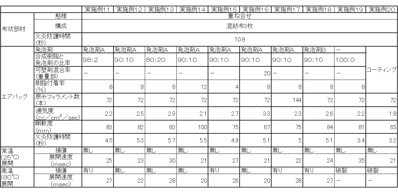
[実施例21、22]
実施例1において、布状部材を綿3枚の重ね合せ(実施例21)、布状部材をナイロン布2枚の重ね合せ(実施例22)を用いた以外は同様にしてエアバッグを製作し、所定の試験を実施した。 [Examples 21 and 22]
In Example 1, an airbag was manufactured in the same manner except that the cloth-like member was overlapped with three pieces of cotton (Example 21) and the cloth-like member was overlapped with two pieces of nylon cloth (Example 22). A predetermined test was conducted.
試験結果を表3に示す。
Table 3 shows the test results.
[実施例23、24]
綿の片面に難燃剤である水酸化アルミニウムを50重量%含んだエチレン-酢酸ビニル共重合体(互応化学工業社製「RD-321」)を70g/m2コーティングした難燃加工綿(厚み0.5mm、火炎防護時間3.8秒)3枚の重ね合せを布状部材として用いた(実施例23)、また、エチレン-酢酸ビニル共重合体(互応化学工業社製「RD-321」)と発泡剤A:アゾジカルボンアミド(三協化成社製「セルマイクC-2」)の比率を90:10として混合した、発泡剤を添加した合成樹脂を固形分濃度30重量%の水分散液とし、綿に含浸処理した発泡処理綿(厚み0.5mm、火炎防護時間4.5秒)3枚の重ね合せを布状部材として用いた(実施例24)以外は実施例1と同様にしてエアバッグを製作し、所定の試験を実施した。 [Examples 23 and 24]
Flame-retardant cotton coated with 70 g / m 2 of an ethylene-vinyl acetate copolymer (“RD-321” manufactured by Kyoyo Chemical Co., Ltd.) containing 50% by weight of aluminum hydroxide as a flame retardant on one side of cotton (thickness 0) .5 mm, flame protection time 3.8 seconds) 3 sheets were used as a cloth-like member (Example 23), and ethylene-vinyl acetate copolymer (“RD-321” manufactured by Kyoyo Chemical Co., Ltd.) And a foaming agent A: azodicarbonamide (“Cermic C-2” manufactured by Sankyo Kasei Co., Ltd.) at a ratio of 90:10, and a synthetic resin added with the foaming agent is used as an aqueous dispersion having a solid content of 30% by weight. In the same manner as in Example 1, except that a superposition of three sheets of foam-treated cotton impregnated in cotton (thickness 0.5 mm, flame protection time 4.5 seconds) was used as a cloth-like member (Example 24). Make a bag and conduct a predetermined test did.
試験結果を表3に示す。
Table 3 shows the test results.
[実施例25]
シリコーン樹脂を片面にコーティングし、乾燥したナイロン布(厚さ0.4mm、火炎防護時間3.3秒)を用い、コーティング面を内側にして、図8に示す形状のインナーバッグを縫製によって作成し、布状部材として用いた以外は実施例1と同様にしてエアバッグを製作し、所定の試験を実施した。 [Example 25]
Silicone resin is coated on one side, a dry nylon cloth (thickness 0.4 mm, flame protection time 3.3 seconds) is used, and the inner surface of the shape shown in FIG. An airbag was manufactured in the same manner as in Example 1 except that it was used as a cloth-like member, and a predetermined test was performed.
試験結果を表3に示す。
Table 3 shows the test results.
[比較例1、2]
布状部材を用いない以外は、実施例9と同様(比較例1)、また、実施例10と同様(比較例2)にしてエアバッグを製作し、所定の試験を実施した。 [Comparative Examples 1 and 2]
Except not using a cloth-like member, an airbag was manufactured in the same manner as in Example 9 (Comparative Example 1) and in the same manner as in Example 10 (Comparative Example 2), and a predetermined test was performed.
試験結果を表3に示す。
Table 3 shows the test results.
[比較例3、4]
布状部材としてナイロン布3枚の重ね合せを用いた以外は、実施例9と同様(比較例3)、また、実施例10と同様(比較例4)にしてエアバッグを製作し、所定の試験を実施した。 [Comparative Examples 3 and 4]
An airbag is manufactured in the same manner as in Example 9 (Comparative Example 3) and in the same manner as in Example 10 (Comparative Example 4) except that three nylon cloths are used as the cloth-like member. The test was conducted.
試験結果を表3に示す。
Table 3 shows the test results.

表1~3に示すとおり、本発明に基づくエアバッグ装置は常温及び高温で展開してもエアバッグが破裂せず、展開速度が十分に速く、乗員の保護性能を向上させることに有効であることが明確である。特にエアバッグにとって厳しい条件である、高温での展開においても破裂が発生せず、十分な乗員の保護性能を発揮しうる。また、軽量で柔軟な布状部材を用い、金属製の案内筒が不要となることから、軽量で収納性に優れたエアバッグ装置とすることが可能であり、自動車で要求されている軽量化に対応できるエアバッグ装置を実現することができる。
As shown in Tables 1 to 3, the airbag device according to the present invention does not rupture even when deployed at room temperature and high temperature, and the deployment speed is sufficiently fast, which is effective in improving the occupant protection performance. It is clear. In particular, rupture does not occur even when deployed at high temperatures, which is a severe condition for airbags, and sufficient occupant protection performance can be achieved. In addition, since a lightweight and flexible cloth-like member is used and a metal guide tube is not required, it is possible to obtain a lightweight and highly packable airbag device, which is required for automobiles. It is possible to realize an airbag device that can cope with the above.
本発明は、車両、特に自動車が衝突した際、車両の乗員を保護する装置に有効である。特に軽量・小型で収納性に優れた上に、乗員の安全を確保する性能にも優れたエアバッグ装置に有効である。
The present invention is effective for a device for protecting a vehicle occupant when a vehicle, particularly an automobile, collides. In particular, it is effective for an airbag device that is lightweight, small and excellent in storability, and also excellent in performance for ensuring the safety of passengers.
1 エアバッグ装置
10 エアバッグ
11 上部取付タブ
12 前部取付片
13 ガス導入口
20 表側布
21 裏側布
22 外周接合部
23、24、25、26 内側接合部
30 気室
31 前部気室
32 後部気室
40 インフレーター
42 ガス噴出し口
45 クランプ
60 布状部材
200 経・緯糸交差部
201 合成樹脂が付着している部分
202 合成樹脂が付着していない部分
211 表面層の単糸
215 第5層の単糸
220、221 経糸と緯糸が接触箇所に合成樹脂が付着している部分
230 合成樹脂が付着している凹部 DESCRIPTION OF SYMBOLS 1Airbag apparatus 10 Airbag 11 Upper attachment tab 12 Front part attachment piece 13 Gas inlet 20 Front side cloth 21 Back side cloth 22 Outer peripheral junction part 23, 24, 25, 26 Inner junction part 30 Air chamber 31 Front air chamber 32 Rear part Air chamber 40 Inflator 42 Gas outlet 45 Clamp 60 Cloth member 200 Warp / weft crossing portion 201 Portion where synthetic resin adheres 202 Portion where synthetic resin does not adhere 211 Single yarn of surface layer 215 5th layer Single yarn 220, 221 Portion where synthetic resin adheres to the contact point of warp and weft 230 Concavity where synthetic resin adheres
10 エアバッグ
11 上部取付タブ
12 前部取付片
13 ガス導入口
20 表側布
21 裏側布
22 外周接合部
23、24、25、26 内側接合部
30 気室
31 前部気室
32 後部気室
40 インフレーター
42 ガス噴出し口
45 クランプ
60 布状部材
200 経・緯糸交差部
201 合成樹脂が付着している部分
202 合成樹脂が付着していない部分
211 表面層の単糸
215 第5層の単糸
220、221 経糸と緯糸が接触箇所に合成樹脂が付着している部分
230 合成樹脂が付着している凹部 DESCRIPTION OF SYMBOLS 1
Claims (32)
- ガスの導入により膨張展開可能なエアバッグと、
ガス噴出し口からガスを噴出して前記エアバッグ内に供給するインフレーターと、
前記エアバッグ内に開口するように前記ガス噴出し口を囲み、少なくとも非溶融繊維を含む布状部材とを備えたことを特徴とするエアバッグ装置。 An airbag that can be inflated and deployed by introducing gas;
An inflator that ejects gas from a gas ejection port and supplies the gas into the airbag;
An airbag device comprising: a cloth-like member that surrounds the gas ejection port so as to open into the airbag and includes at least non-melted fibers. - 前記布状部材が非溶融繊維を30~100重量%含むことを特徴とする請求項1に記載のエアバッグ装置。 2. The airbag device according to claim 1, wherein the cloth-like member contains 30 to 100% by weight of non-molten fiber.
- 前記非溶融繊維が、少なくともセルロース系繊維、アクリル系繊維、アラミド系繊維、ビニロン繊維、炭素繊維、セラミック系繊維、動物性天然繊維の何れかを含むことを特徴とする請求項1または2のいずれかに記載のエアバッグ装置。 The said non-melting fiber contains any one of a cellulose fiber, an acrylic fiber, an aramid fiber, a vinylon fiber, a carbon fiber, a ceramic fiber, and an animal natural fiber at least. The airbag apparatus of crab.
- 前記布状部材の火炎に対する防護時間が3.5秒以上であることを特徴とする請求項1~3のいずれかに記載のエアバッグ装置。 The airbag device according to any one of claims 1 to 3, wherein a protection time against the flame of the cloth-like member is 3.5 seconds or more.
- 前記布状部材が、少なくとも難燃処理、防炎処理、耐熱処理、発泡処理の何れかを施されたことを特徴とする請求項1~4のいずれかに記載のエアバッグ装置。 The airbag device according to any one of claims 1 to 4, wherein the cloth-like member is subjected to at least one of a flame retardant treatment, a flameproof treatment, a heat treatment, and a foaming treatment.
- 前記布状部材が少なくとも短繊維を含むことを特徴とする請求項1~5のいずれかに記載のエアバッグ装置。 The airbag device according to any one of claims 1 to 5, wherein the cloth-like member includes at least short fibers.
- 前記エアバッグ装置が、さらにエアバッグ内に配置されて前記ガス噴出し口からのガスをエアバッグの膨張可能な領域に案内するインナーバッグまたはインナーチューブを備えたことを特徴とする請求項1に記載のエアバッグ装置。 2. The airbag apparatus according to claim 1, further comprising an inner bag or an inner tube which is disposed in the airbag and guides gas from the gas ejection port to an inflatable region of the airbag. The airbag apparatus as described.
- ガスの導入により膨張展開可能なエアバッグと、
ガス噴出し口からガスを噴出して前記エアバッグ内に供給するインフレーターとを備えたエアバッグ装置において、
前記エアバッグに少なくとも発泡剤を添加した合成樹脂が付着していることを特徴とするエアバッグ装置。 An airbag that can be inflated and deployed by introducing gas;
In an airbag device including an inflator that ejects gas from a gas ejection port and supplies the gas into the airbag,
A synthetic resin to which at least a foaming agent is added is attached to the airbag. - 前記エアバッグに、少なくとも50%以上の経・緯糸の交差部表面および糸を構成する単糸の表層~第5層に掛けて、少なくとも発泡剤を添加した合成樹脂が付着していることを特徴とする請求項8に記載のエアバッグ装置。 A synthetic resin to which at least a foaming agent is added is attached to the air bag over at least 50% or more of the warp / weft intersection surface and the surface layer to the fifth layer of the single yarn constituting the yarn. The airbag device according to claim 8.
- 前記エアバッグ装置において、さらに、エアバッグ内に開口するように、インフレーターのガス噴出し口を囲む布状部材を備えたことを特徴とする請求項8に記載のエアバッグ装置。 The airbag apparatus according to claim 8, further comprising a cloth-like member surrounding a gas ejection port of the inflator so as to open into the airbag.
- 前記布状部材が少なくとも非溶融繊維を含むことを特徴とする請求項10に記載のエアバッグ装置。 The airbag device according to claim 10, wherein the cloth-like member includes at least a non-melting fiber.
- 前記布状部材が、少なくとも難燃処理、防炎処理、耐熱処理、発泡処理の何れかを施されたことを特徴とする請求項10または11に記載のエアバッグ装置。 The airbag device according to claim 10 or 11, wherein the cloth-like member is subjected to at least one of a flame retardant treatment, a flame proof treatment, a heat resistant treatment, and a foaming treatment.
- 少なくとも発泡剤を添加した合成樹脂の基布への付着率が0.1~20重量%であることを特徴とする、請求項8~12に記載のエアバッグ装置。 The airbag device according to any one of claims 8 to 12, wherein the adhesion rate of the synthetic resin to which at least a foaming agent is added to the base fabric is 0.1 to 20% by weight.
- 前記発泡剤を添加した合成樹脂において、合成樹脂と発泡剤の重量比率が99:1~60:40であることを特徴とする、請求項8~13に記載のエアバッグ装置。 14. The airbag device according to claim 8, wherein in the synthetic resin to which the foaming agent is added, a weight ratio of the synthetic resin to the foaming agent is 99: 1 to 60:40.
- 前記合成樹脂が、C・H・N・Oより選ばれた元素からなり、発泡剤が化学発泡剤の組合せであることを特徴とする、請求項8~14に記載のエアバッグ装置。 15. The airbag device according to claim 8, wherein the synthetic resin is made of an element selected from C, H, N, and O, and the foaming agent is a combination of chemical foaming agents.
- 前記発泡剤が、少なくとも有機系発泡剤であることを特徴とする、請求項8~15に記載のエアバッグ装置。 16. The airbag apparatus according to claim 8, wherein the foaming agent is at least an organic foaming agent.
- 前記発泡剤が、少なくともNを含有することを特徴とする、請求項8~16に記載のエアバッグ装置。 The airbag device according to any one of claims 8 to 16, wherein the foaming agent contains at least N.
- 前記発泡剤が、少なくともアゾ系化合物を含有することを特徴とする、請求項8~17に記載のエアバッグ装置。 The airbag device according to any one of claims 8 to 17, wherein the foaming agent contains at least an azo compound.
- 発泡剤を添加した合成樹脂に、さらに可塑剤を添加することを特徴とする、請求項8~18に記載のエアバッグ装置。 The airbag device according to any one of claims 8 to 18, wherein a plasticizer is further added to the synthetic resin to which the foaming agent is added.
- 前記可塑剤がリン酸エステル系化合物であることを特徴とする、請求項19に記載のエアバッグ装置。 20. The airbag device according to claim 19, wherein the plasticizer is a phosphate ester compound.
- 発泡剤を添加した合成樹脂を基布に付着させる手段が、基布に水を付与した後、発泡剤を添加した合成樹脂の水系希釈液に含浸することを特徴とする、請求項8~20に記載のエアバッグ装置。 The means for adhering the synthetic resin to which the foaming agent has been added to the base fabric impregnates the aqueous dilution of the synthetic resin to which the foaming agent has been added after water is applied to the base fabric. The airbag apparatus as described in.
- 発泡剤を添加した合成樹脂の水系希釈液を含浸する前に、基布にカレンダー加工を行うことを特徴とする、請求項8~21に記載のエアバッグ装置。 The airbag device according to any one of claims 8 to 21, wherein the base fabric is calendered before impregnating with an aqueous dilution of a synthetic resin to which a foaming agent is added.
- 前記インフレーターが固体のガス発生剤を使用することを特徴とする請求項1または8に記載のエアバッグ装置。 The airbag device according to claim 1 or 8, wherein the inflator uses a solid gas generating agent.
- 前記インフレーターが複数のガス噴出し口から放射状にガスを噴出することを特徴とする請求項23に記載のエアバッグ装置。 The airbag device according to claim 23, wherein the inflator ejects gas radially from a plurality of gas ejection ports.
- 前記エアバッグが、少なくとも2枚の布が、外周縁部に設けられた外周接合部と、該外周接合部の内側に設けられた内側接合部とで相互に接合されたカーテンエアバッグであることを特徴とする請求項1~24に記載のエアバッグ装置。 The airbag is a curtain airbag in which at least two pieces of cloth are joined to each other by an outer peripheral joint provided at an outer peripheral edge and an inner joint provided inside the outer peripheral joint. The airbag device according to any one of claims 1 to 24.
- 前記内側接合部が複数のドット状であり、前記外周接合部から独立し且つ相互に独立して設けられていることを特徴とする請求項25に記載のエアバッグ装置。 26. The airbag device according to claim 25, wherein the inner joint portion has a plurality of dots, and is provided independently of the outer peripheral joint portion and independently of each other.
- 前記複数のドット状の内側接合部の個数が15個以上160個以下であることを特徴とする請求項26に記載のエアバッグ装置。 27. The airbag device according to claim 26, wherein the number of the plurality of dot-shaped inner joint portions is 15 or more and 160 or less.
- 前記複数のドット状の内側接合部が0.7cm2/個以上13cm2/個以下の面積であることを特徴とする請求項26又は27に記載のエアバッグ装置。 Airbag device according to claim 26 or 27 inner joint portion of the plurality of dot-shaped, characterized in that an area of 0.7 cm 2 / FOB 13cm 2 / number less.
- 前記複数のドット状の内側接合部の形状が、線分、円形、楕円形、四角形、菱形、多角形またはそれらを部分的に変形した形状であることを特徴とする請求項26~28のいずれかに記載のエアバッグ装置。 The shape of the plurality of dot-shaped inner joints is a line segment, a circle, an ellipse, a quadrangle, a rhombus, a polygon, or a shape obtained by partially deforming them. The airbag apparatus of crab.
- 前記複数のドット状の内側接合部が、実質的に膨張可能な領域の全面に亘り設けられていることを特徴とする請求項26~29のいずれかに記載のエアバッグ装置。 The airbag device according to any one of claims 26 to 29, wherein the plurality of dot-shaped inner joint portions are provided over the entire surface of a substantially inflatable region.
- 前記少なくとも2枚の布が、織布であり、前記カーテンエアバッグの長手方向に平行な直線と、前記織布の経糸との交差角が20~70度であることを特徴とする請求項25に記載のエアバッグ装置。 26. The at least two cloths are woven cloths, and an intersection angle between a straight line parallel to the longitudinal direction of the curtain airbag and a warp of the woven cloth is 20 to 70 degrees. The airbag apparatus as described in.
- エアバッグに使用される原糸の単糸繊度が6dtex以上15dtex以下であることを特徴とする、請求項1~31に記載のエアバッグ装置。 The airbag device according to any one of claims 1 to 31, wherein the single yarn fineness of the yarn used for the airbag is 6 dtex or more and 15 dtex or less.
Priority Applications (3)
| Application Number | Priority Date | Filing Date | Title |
|---|---|---|---|
| CN201180011259.0A CN102781734B (en) | 2010-02-24 | 2011-01-21 | Airbag apparatus |
| EP11747106.0A EP2540580B1 (en) | 2010-02-24 | 2011-01-21 | Airbag device |
| JP2012501704A JPWO2011105142A1 (en) | 2010-02-24 | 2011-01-21 | Airbag device |
Applications Claiming Priority (4)
| Application Number | Priority Date | Filing Date | Title |
|---|---|---|---|
| JP2010038275 | 2010-02-24 | ||
| JP2010-038275 | 2010-02-24 | ||
| JP2011-001625 | 2011-01-07 | ||
| JP2011001625 | 2011-01-07 |
Publications (1)
| Publication Number | Publication Date |
|---|---|
| WO2011105142A1 true WO2011105142A1 (en) | 2011-09-01 |
Family
ID=44506564
Family Applications (1)
| Application Number | Title | Priority Date | Filing Date |
|---|---|---|---|
| PCT/JP2011/051085 WO2011105142A1 (en) | 2010-02-24 | 2011-01-21 | Airbag device |
Country Status (4)
| Country | Link |
|---|---|
| EP (1) | EP2540580B1 (en) |
| JP (1) | JPWO2011105142A1 (en) |
| CN (1) | CN102781734B (en) |
| WO (1) | WO2011105142A1 (en) |
Cited By (6)
| Publication number | Priority date | Publication date | Assignee | Title |
|---|---|---|---|---|
| JP2013060671A (en) * | 2011-09-11 | 2013-04-04 | Katayama Co Ltd | Method of producing seamless fabric and apparatus for producing the same |
| WO2013102643A1 (en) * | 2012-01-05 | 2013-07-11 | Takata AG | Airbag module |
| CN103866573B (en) * | 2012-12-14 | 2017-08-04 | 东丽纤维研究所(中国)有限公司 | A kind of air bag coated fabric and its production method and purposes |
| JP2018172103A (en) * | 2017-03-31 | 2018-11-08 | 豊田合成株式会社 | Heat-resistant reinforcement fabric for airbag |
| WO2019177033A1 (en) * | 2018-03-13 | 2019-09-19 | 東洋紡株式会社 | Base fabric for coated airbag, manufacturing method therefor, and coating composition used for said manufacturing method |
| CN114407740A (en) * | 2021-12-15 | 2022-04-29 | 杨旭 | A high security children's seat for new energy automobile intelligence passenger cabin |
Families Citing this family (6)
| Publication number | Priority date | Publication date | Assignee | Title |
|---|---|---|---|---|
| CN103028214B (en) * | 2012-12-29 | 2016-06-22 | 泉州师范学院 | A kind of automatic fire prevention packaging bag |
| DE202013004273U1 (en) * | 2013-05-07 | 2013-05-27 | Key Safety Systems, Inc. | Airbag for a motor vehicle |
| EP2930069B1 (en) * | 2014-04-07 | 2017-09-13 | Autoliv Development AB | Improvements in or relating to air-bags |
| DE102015108423A1 (en) | 2015-05-28 | 2015-09-17 | Takata AG | Airbag for an airbag module |
| KR102440403B1 (en) * | 2015-09-09 | 2022-09-05 | 현대모비스 주식회사 | Knee air bag apparatus and method for manufacturing of knee air bag apparatus |
| JP6596742B2 (en) * | 2017-12-28 | 2019-10-30 | 本田技研工業株式会社 | Airbag device |
Citations (9)
| Publication number | Priority date | Publication date | Assignee | Title |
|---|---|---|---|---|
| JPH08104194A (en) * | 1994-10-06 | 1996-04-23 | Asahi Chem Ind Co Ltd | Air bag |
| JP2001355144A (en) * | 2000-06-13 | 2001-12-26 | Asahi Kasei Corp | Base fabric for airbag and airbag |
| JP2003002151A (en) * | 2001-06-20 | 2003-01-08 | Nippon Plast Co Ltd | Car air bag for side impact |
| JP3689845B2 (en) | 2001-05-10 | 2005-08-31 | 豊田合成株式会社 | Head protection airbag device airbag |
| JP2006249655A (en) * | 2000-04-07 | 2006-09-21 | Asahi Kasei Chemicals Corp | Coated fabric and air bag |
| JP2007269184A (en) * | 2006-03-31 | 2007-10-18 | Seiren Co Ltd | Base fabric for airbag, its manufacturing method and airbag using the same |
| JP2009056830A (en) * | 2007-08-30 | 2009-03-19 | Ashimori Ind Co Ltd | Manufacturing method of air bag, air bag and air bag device |
| JP2009214616A (en) | 2008-03-07 | 2009-09-24 | Ashimori Ind Co Ltd | Airbag device |
| JP2009292348A (en) * | 2008-06-06 | 2009-12-17 | Ashimori Ind Co Ltd | Air bag device |
Family Cites Families (4)
| Publication number | Priority date | Publication date | Assignee | Title |
|---|---|---|---|---|
| ES2093107T3 (en) * | 1990-10-03 | 1996-12-16 | Teijin Ltd | FABRIC NOT WOVEN IN HEAT RESISTANT FABRIC AND METHOD TO MANUFACTURE SUCH FABRIC. |
| JP3833119B2 (en) * | 2000-04-07 | 2006-10-11 | 旭化成ケミカルズ株式会社 | Coating fabric and airbag |
| KR20080030411A (en) * | 2006-09-30 | 2008-04-04 | (주) 유니플라텍 | Manufacturing method of drying carbon non-woven fabrics for plane heater and drying carbon non-woven fabrics manufactured by thereof |
| WO2009110318A1 (en) * | 2008-03-07 | 2009-09-11 | 芦森工業株式会社 | Airbag device |
-
2011
- 2011-01-21 WO PCT/JP2011/051085 patent/WO2011105142A1/en active Application Filing
- 2011-01-21 EP EP11747106.0A patent/EP2540580B1/en not_active Not-in-force
- 2011-01-21 JP JP2012501704A patent/JPWO2011105142A1/en active Pending
- 2011-01-21 CN CN201180011259.0A patent/CN102781734B/en not_active Expired - Fee Related
Patent Citations (9)
| Publication number | Priority date | Publication date | Assignee | Title |
|---|---|---|---|---|
| JPH08104194A (en) * | 1994-10-06 | 1996-04-23 | Asahi Chem Ind Co Ltd | Air bag |
| JP2006249655A (en) * | 2000-04-07 | 2006-09-21 | Asahi Kasei Chemicals Corp | Coated fabric and air bag |
| JP2001355144A (en) * | 2000-06-13 | 2001-12-26 | Asahi Kasei Corp | Base fabric for airbag and airbag |
| JP3689845B2 (en) | 2001-05-10 | 2005-08-31 | 豊田合成株式会社 | Head protection airbag device airbag |
| JP2003002151A (en) * | 2001-06-20 | 2003-01-08 | Nippon Plast Co Ltd | Car air bag for side impact |
| JP2007269184A (en) * | 2006-03-31 | 2007-10-18 | Seiren Co Ltd | Base fabric for airbag, its manufacturing method and airbag using the same |
| JP2009056830A (en) * | 2007-08-30 | 2009-03-19 | Ashimori Ind Co Ltd | Manufacturing method of air bag, air bag and air bag device |
| JP2009214616A (en) | 2008-03-07 | 2009-09-24 | Ashimori Ind Co Ltd | Airbag device |
| JP2009292348A (en) * | 2008-06-06 | 2009-12-17 | Ashimori Ind Co Ltd | Air bag device |
Non-Patent Citations (1)
| Title |
|---|
| See also references of EP2540580A4 * |
Cited By (9)
| Publication number | Priority date | Publication date | Assignee | Title |
|---|---|---|---|---|
| JP2013060671A (en) * | 2011-09-11 | 2013-04-04 | Katayama Co Ltd | Method of producing seamless fabric and apparatus for producing the same |
| WO2013102643A1 (en) * | 2012-01-05 | 2013-07-11 | Takata AG | Airbag module |
| CN103866573B (en) * | 2012-12-14 | 2017-08-04 | 东丽纤维研究所(中国)有限公司 | A kind of air bag coated fabric and its production method and purposes |
| JP2018172103A (en) * | 2017-03-31 | 2018-11-08 | 豊田合成株式会社 | Heat-resistant reinforcement fabric for airbag |
| WO2019177033A1 (en) * | 2018-03-13 | 2019-09-19 | 東洋紡株式会社 | Base fabric for coated airbag, manufacturing method therefor, and coating composition used for said manufacturing method |
| JPWO2019177033A1 (en) * | 2018-03-13 | 2021-03-11 | 東洋紡株式会社 | Base fabric for coated airbags, methods for producing the same, and coating compositions used for the method of producing the same. |
| US11465582B2 (en) | 2018-03-13 | 2022-10-11 | Toyobo Co., Ltd. | Base fabric for coated airbag, manufacturing method therefor, and coating composition used for said manufacturing method |
| JP7272346B2 (en) | 2018-03-13 | 2023-05-12 | 東洋紡株式会社 | Coated airbag base fabric, method for producing the same, and coating composition used for the method for producing the same |
| CN114407740A (en) * | 2021-12-15 | 2022-04-29 | 杨旭 | A high security children's seat for new energy automobile intelligence passenger cabin |
Also Published As
| Publication number | Publication date |
|---|---|
| EP2540580A1 (en) | 2013-01-02 |
| JPWO2011105142A1 (en) | 2013-06-20 |
| EP2540580A4 (en) | 2013-07-24 |
| CN102781734A (en) | 2012-11-14 |
| CN102781734B (en) | 2016-02-03 |
| EP2540580B1 (en) | 2015-03-25 |
Similar Documents
| Publication | Publication Date | Title |
|---|---|---|
| WO2011105142A1 (en) | Airbag device | |
| EP3020607B1 (en) | Air-bag | |
| WO2017057300A1 (en) | Fabric for airbag, and airbag | |
| KR20100117527A (en) | Tube typed fabric substrate for introducing gas into airbag and preparation method thereof | |
| US10449922B2 (en) | Air-bag | |
| JP2010203023A (en) | Woven fabric for air bag and air bag | |
| JP5335369B2 (en) | Airbag fabrics and airbags | |
| EP2586664B1 (en) | Method of Producing a Curtain Airbag | |
| JP5060387B2 (en) | Sewing thread for airbag and airbag using the same | |
| JP2006027373A (en) | Air bag | |
| JP2009227017A (en) | Airbag and manufacturing method of the same | |
| JP3927430B2 (en) | Fabric for laminated air bag and air bag using the same | |
| JP2007320511A (en) | Air bag | |
| JP2010013770A (en) | Woven fabric for airbag and airbag | |
| EP3680136B1 (en) | Airbag | |
| JP2011126429A (en) | Curtain airbag | |
| JP5066014B2 (en) | Airbag | |
| JP2006159990A (en) | Inflatable curtain | |
| JP2006168665A (en) | Air bag | |
| JP2017094799A (en) | Air bag | |
| JP2015093657A (en) | Air bag for protecting occupant | |
| JP6263045B2 (en) | Curtain airbag | |
| JP2014051152A (en) | Occupant-protecting air bag | |
| JP2010018929A (en) | Method of manufacturing airbag base cloth and airbag | |
| JP2019025995A (en) | Air bag |
Legal Events
| Date | Code | Title | Description |
|---|---|---|---|
| WWE | Wipo information: entry into national phase |
Ref document number: 201180011259.0 Country of ref document: CN |
|
| 121 | Ep: the epo has been informed by wipo that ep was designated in this application |
Ref document number: 11747106 Country of ref document: EP Kind code of ref document: A1 |
|
| WWE | Wipo information: entry into national phase |
Ref document number: 2012501704 Country of ref document: JP |
|
| WWE | Wipo information: entry into national phase |
Ref document number: 2011747106 Country of ref document: EP |
|
| NENP | Non-entry into the national phase |
Ref country code: DE |