WO2011104993A1 - 画像符号化装置、画像復号装置、および、データ構造 - Google Patents
画像符号化装置、画像復号装置、および、データ構造 Download PDFInfo
- Publication number
- WO2011104993A1 WO2011104993A1 PCT/JP2010/073618 JP2010073618W WO2011104993A1 WO 2011104993 A1 WO2011104993 A1 WO 2011104993A1 JP 2010073618 W JP2010073618 W JP 2010073618W WO 2011104993 A1 WO2011104993 A1 WO 2011104993A1
- Authority
- WO
- WIPO (PCT)
- Prior art keywords
- prediction
- unit
- image
- parameter
- group
- Prior art date
Links
Images


Classifications
-
- H—ELECTRICITY
- H04—ELECTRIC COMMUNICATION TECHNIQUE
- H04N—PICTORIAL COMMUNICATION, e.g. TELEVISION
- H04N19/00—Methods or arrangements for coding, decoding, compressing or decompressing digital video signals
- H04N19/10—Methods or arrangements for coding, decoding, compressing or decompressing digital video signals using adaptive coding
- H04N19/102—Methods or arrangements for coding, decoding, compressing or decompressing digital video signals using adaptive coding characterised by the element, parameter or selection affected or controlled by the adaptive coding
- H04N19/103—Selection of coding mode or of prediction mode
- H04N19/11—Selection of coding mode or of prediction mode among a plurality of spatial predictive coding modes
-
- H—ELECTRICITY
- H04—ELECTRIC COMMUNICATION TECHNIQUE
- H04N—PICTORIAL COMMUNICATION, e.g. TELEVISION
- H04N19/00—Methods or arrangements for coding, decoding, compressing or decompressing digital video signals
- H04N19/10—Methods or arrangements for coding, decoding, compressing or decompressing digital video signals using adaptive coding
- H04N19/189—Methods or arrangements for coding, decoding, compressing or decompressing digital video signals using adaptive coding characterised by the adaptation method, adaptation tool or adaptation type used for the adaptive coding
- H04N19/196—Methods or arrangements for coding, decoding, compressing or decompressing digital video signals using adaptive coding characterised by the adaptation method, adaptation tool or adaptation type used for the adaptive coding being specially adapted for the computation of encoding parameters, e.g. by averaging previously computed encoding parameters
- H04N19/197—Methods or arrangements for coding, decoding, compressing or decompressing digital video signals using adaptive coding characterised by the adaptation method, adaptation tool or adaptation type used for the adaptive coding being specially adapted for the computation of encoding parameters, e.g. by averaging previously computed encoding parameters including determination of the initial value of an encoding parameter
-
- H—ELECTRICITY
- H04—ELECTRIC COMMUNICATION TECHNIQUE
- H04N—PICTORIAL COMMUNICATION, e.g. TELEVISION
- H04N19/00—Methods or arrangements for coding, decoding, compressing or decompressing digital video signals
- H04N19/46—Embedding additional information in the video signal during the compression process
-
- H—ELECTRICITY
- H04—ELECTRIC COMMUNICATION TECHNIQUE
- H04N—PICTORIAL COMMUNICATION, e.g. TELEVISION
- H04N19/00—Methods or arrangements for coding, decoding, compressing or decompressing digital video signals
- H04N19/70—Methods or arrangements for coding, decoding, compressing or decompressing digital video signals characterised by syntax aspects related to video coding, e.g. related to compression standards
Definitions
- the present invention relates to an image encoding apparatus that encodes an image and generates encoded data.
- the present invention also relates to an image decoding apparatus that decodes encoded data generated using such an image encoding apparatus.
- a moving image encoding device In order to efficiently transmit or record moving images, a moving image encoding device is used.
- a specific moving picture encoding method for example, H.264 is used.
- VCEG Video Coding Expert Group
- an image (picture) constituting a moving image is obtained by dividing a slice obtained by dividing an image, a macroblock obtained by dividing the slice, and a macroblock.
- a slice obtained by dividing an image
- a macroblock obtained by dividing the slice
- a macroblock obtained by dividing the slice
- a macroblock obtained by dividing the slice
- a macroblock obtained by dividing the slice
- a macroblock is managed by a hierarchical structure composed of sub-blocks, and are usually encoded for each sub-block.
- a predicted image is usually generated based on a local decoded image obtained by encoding / decoding an input image, and difference data between the predicted image and the input image is encoded. It becomes.
- methods for generating a predicted image methods called inter-frame prediction (inter prediction) and intra-frame prediction (intra prediction) are known.
- a prediction image in a prediction target frame is generated by applying motion compensation using a motion vector to a reference image in a reference frame in which the entire frame is decoded.
- intra prediction predicted images in the frame are sequentially generated based on locally decoded images in the same frame.
- the prediction image is generally generated based on a prediction parameter such as a motion vector, a weighting coefficient, or a prediction mode.
- prediction mode information that is information indicating which prediction mode has been selected for each prediction target region together with the difference data.
- the amount of encoded data increases due to the prediction mode information.
- the present invention has been made in view of the above problems, and an object of the present invention is to provide an image encoding device capable of reducing the amount of code for specifying a prediction parameter without sacrificing encoding efficiency, Another object of the present invention is to realize an image decoding apparatus capable of decoding encoded data generated by such an image encoding apparatus.
- an image encoding device divides a predicted image into a plurality of unit regions in an image encoding device that encodes a difference between an input image and a predicted image, and Classification means for classifying a plurality of prediction units included in a unit region into a first group or a second group, and a prediction parameter for specifying a prediction image generation method in each prediction unit belonging to the first group, First selection means for selecting from a basic set of predetermined prediction parameters, and prediction parameters for specifying a prediction image generation method in each prediction unit belonging to the second group are selected by the first selection means.
- a reduced set that includes at least a part of the predicted parameters that are less than or equal to the number of prediction parameters included in the basic set.
- a prediction parameter that specifies a method of generating a predicted image in each prediction unit belonging to the second group is included in the same unit region as the second group. From a prediction parameter that is a reduced set that includes at least a part of the prediction parameters selected by the first selection unit for each prediction unit belonging to the first group, and is equal to or less than the number of prediction parameters included in the basic set. The reduction set is selected, and the prediction parameter selected by the second selection unit is encoded.
- the prediction parameter for each prediction unit is generally correlated with the prediction parameter for the prediction unit located in the vicinity of the prediction unit, the prediction parameter selected for each prediction unit belonging to the first group. Is likely to be an appropriate prediction parameter for each prediction unit belonging to the second group. That is, for each prediction unit belonging to the second group, there is a high possibility that the prediction parameter selected from the reduced set is an appropriate prediction parameter. Therefore, according to the above configuration, the prediction parameter can be encoded without reducing the encoding efficiency.
- the reduced set is a reduced set including at least a part of the prediction parameters selected by the first selection unit, and is equal to or less than the number of prediction parameters included in the basic set. Since the set includes prediction parameters, it is possible to reduce the code amount of information indicating which prediction parameter is selected for each prediction unit belonging to the second group.
- the image coding apparatus is an image coding apparatus that codes a difference between an input image and a predicted image.
- a prediction parameter that specifies a method for generating a predicted image in each prediction unit is set in the prediction unit.
- a prediction parameter encoding unit that encodes whether the selection has been made.
- a prediction parameter for each prediction unit has a correlation with a prediction parameter for a prediction unit located in the vicinity of the prediction unit. Therefore, the reduced set is most likely to include a prediction parameter in generating a prediction image in the prediction unit.
- the reduced set is composed of at least a part of the prediction parameters for the prediction unit located in the vicinity of the prediction unit, the number of prediction parameters included in the reduced set is for the prediction units other than the prediction unit. The number is smaller than the number of prediction parameters included in the parameter set including the prediction parameters.
- the image encoding apparatus can generate encoded data with a small amount of code without sacrificing encoding efficiency by adopting the above configuration.
- the image decoding apparatus determines the difference between the original image and the predicted image, which prediction parameter is selected from among a plurality of prediction parameters that specify a predicted image generation method for each prediction unit.
- a plurality of prediction units included in each of a plurality of unit regions that constitute a prediction image are assigned to a first group or a second group
- a prediction parameter for specifying a prediction image generation method in each prediction unit belonging to the first group is determined in advance with reference to classification means for classifying into the group and selection information for each prediction unit belonging to the first group.
- Selection information for each prediction unit belonging to the first selection means and the second group selected from the basic set of the predicted parameters is a reduced set including at least a part of the prediction parameter selected by the first selection unit, And a second selection means for selecting from a reduced set of prediction parameters that are equal to or less than the number of prediction parameters included in the basic set.
- a prediction parameter that specifies a method for generating a predicted image in each prediction unit belonging to the second group is included in the same unit region as that of the second group.
- the prediction parameter for each prediction unit is generally correlated with the prediction parameter for the prediction unit located in the vicinity of the prediction unit, the prediction parameter selected for each prediction unit belonging to the first group. Is likely to be an appropriate prediction parameter for each prediction unit belonging to the second group. Therefore, according to the above configuration, the prediction parameter can be decoded from the selection information with a smaller code amount without reducing the encoding efficiency.
- the image decoding apparatus determines the difference between the input image and the predicted image, which prediction parameter is selected from among a plurality of prediction parameters that specify a predicted image generation method for each prediction unit.
- a prediction parameter that specifies a method for generating a predicted image in each prediction unit with reference to the selection information, It includes a selection means for selecting from a reduced set including at least a part of a prediction parameter for designating a prediction image generation method in a decoded prediction unit located in the vicinity.
- a prediction parameter for each prediction unit has a correlation with a prediction parameter for a prediction unit located in the vicinity of the prediction unit. Therefore, the reduced set is most likely to include a prediction parameter in generating a prediction image in the prediction unit.
- the reduced set is composed of at least a part of the prediction parameters for the prediction unit located in the vicinity of the prediction unit, the number of prediction parameters included in the reduced set is for the prediction units other than the prediction unit. The number is smaller than the number of prediction parameters included in the parameter set including the prediction parameters.
- an image encoding apparatus having a configuration corresponding to the above configuration can generate encoded data with a small code amount without sacrificing encoding efficiency.
- the image decoding apparatus having the above configuration can decode such encoded data with a small code amount.
- the data structure of the encoded data according to the present invention is such that any prediction parameter is selected from among a plurality of prediction parameters that specify the difference between the input image and the prediction image and the prediction image generation method for each prediction unit.
- a data structure of encoded data obtained by encoding together with selection information indicating whether or not a prediction image is generated by decoding the encoded data, and specifying a prediction image generation method in each prediction unit Including selection information referred to for selecting a parameter from a reduced set including at least a part of a prediction parameter that specifies a method of generating a predicted image in a decoded prediction unit located in the vicinity of the prediction unit; It is characterized by that.
- a prediction parameter for each prediction unit has a correlation with a prediction parameter for a prediction unit located in the vicinity of the prediction unit. Therefore, the reduced set is most likely to include a prediction parameter in generating a prediction image in the prediction unit.
- the reduced set since the reduced set includes at least a part of prediction parameters for a prediction unit located in the vicinity of the prediction unit, the number of prediction parameters specified by the selection information is a prediction unit other than the prediction unit. Is less than the number of prediction parameters included in the parameter set made up of prediction parameters.
- the encoded data having the above configuration is encoded data with a reduced code amount without sacrificing encoding efficiency.
- the image encoding device is an image encoding device that encodes a difference between an input image and a predicted image, and divides the predicted image into a plurality of unit regions and is included in each unit region.
- a prediction means for specifying a prediction parameter for specifying a prediction image generation method in each prediction unit belonging to the first group and a classification unit that classifies the plurality of prediction units into a first group or a second group A prediction parameter selected by the first selection unit; a first selection unit that selects from a basic set of parameters; and a prediction parameter that specifies a method for generating a predicted image in each prediction unit belonging to the second group.
- a reduced set that includes at least a part of the prediction parameter that is equal to or less than the number of prediction parameters included in the basic set.
- Second prediction means for selecting from a network, and for each prediction unit belonging to the first group, which prediction parameter the first selection means has selected, and each of the prediction group belonging to the first group Prediction parameter encoding means for encoding which prediction parameter is selected by the second selection means for the prediction unit.
- the image coding apparatus configured as described above, it is possible to reduce the code amount for designating the prediction parameter without sacrificing the coding efficiency.
- H. 2 is a diagram illustrating an intra prediction mode used for intra prediction in the H.264 / MPEG-4 AVC standard, together with an index assigned to each prediction mode.
- FIG. It is a figure for demonstrating operation
- (A) is a flowchart which shows the 1st example of the production
- (b) is a flowchart which shows the 2nd example of the production
- (c) is a flowchart showing a third example of a reduced set generation operation in the reduced set derivation unit. It is a flowchart which shows an example of the flow of the decoding process in the 2nd prediction parameter decoding part with which a prediction parameter decoding part is provided. It is a figure for demonstrating the other structural example of a prediction parameter decoding part.
- (A) is a flowchart which shows the production
- (b) has shown an example of the neighborhood subblock area
- FIG. 1 It is a block diagram which shows the structure of the prediction parameter determination part with which an MB encoding part is provided. It is a figure for demonstrating operation
- (A) has shown the example of the prediction mode which the 1st prediction parameter determination part selected with respect to each subblock which belongs to a 1st group among each subblock which comprises macroblock MB,
- the moving picture decoding apparatus 1 includes H.264 as a part thereof. This is a moving picture coding apparatus using the technology adopted in the H.264 / MPEG-4 AVC standard.
- the moving picture decoding apparatus 1 is an apparatus that generates and outputs a decoded image # 2 by decoding input encoded data # 1.
- the moving image encoding apparatus 1 divides a unit area on the image indicated by the encoded data # 1 into a plurality of prediction target areas (prediction units), and uses a prediction image generated for each prediction target area. Decoded image # 2 is generated.
- the above unit area is referred to as H.264.
- the present invention will be described with reference to an example in which a macroblock in the H.264 / MPEG-4 AVC standard is used, and the prediction target area is a subblock in the macroblock, but the present invention is not limited to this.
- the unit area may be an area larger than a macroblock, or may be an area overlapping with a plurality of macroblocks.
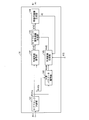
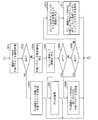
- FIG. 1 is a block diagram showing a configuration of the moving picture decoding apparatus 1.
- the moving picture decoding apparatus 1 includes a variable length code demultiplexing unit 11, a header information decoding unit 12, an MB setting unit 13, an MB decoding unit 14, and a frame memory 15.
- the encoded data # 1 input to the video decoding device 1 is input to the variable length demultiplexing unit 11.
- the variable length demultiplexing unit 11 demultiplexes the input encoded data # 1, thereby converting the encoded data # 1 into header encoded data # 11a that is encoded data related to header information, and a macroblock Separated into MB encoded data # 11b, which is encoded data relating to (unit area), header encoded data # 11a is output to header information decoding unit 12, and MB encoded data # 11b is output to MB setting unit 13, respectively. .
- the header information decoding unit 12 decodes the header information # 12 from the encoded header data # 11a.
- the header information # 12 is information including the size of the input image.
- the MB setting unit 13 separates the MB encoded data # 11b into encoded data # 13 corresponding to each macroblock based on the input header information # 12, and sequentially outputs the encoded data # 11b to the MB decoding unit 14. .
- the MB decoding unit 14 generates and outputs a decoded image # 2 corresponding to each macroblock by sequentially decoding the encoded data # 13 corresponding to each input macroblock.
- the decoded image # 2 is also output to the frame memory 15.
- the configuration of the MB decoding unit 14 will be described later and will not be described here.
- the decoded image # 2 is recorded in the frame memory 15.
- decoded images corresponding to all the macroblocks that precede the macroblock in the raster scan order are recorded.
- FIG. 2 is a block diagram showing a configuration of the MB decoding unit 14.
- the MB decoding unit 14 includes a sub-block dividing unit 141, a prediction residual decoding unit 142, a sub-block decoded image generation unit 143, a prediction parameter decoding unit 144, a prediction image generation unit 145, and MB decoding.
- An image generation unit 146 is provided.
- the sub-block dividing unit 141 is activated when encoded data # 13 in units of macro blocks is input, and each sub block (each prediction target region) constituting the macro block (unit region) within the corresponding macro block.
- Sub-block position information # 141a indicating the position and sub-block encoded data # 141b which is encoded data related to the sub-block indicated by the sub-block position information # 141a are sequentially output in a predetermined order. Note that the method used in the video encoding apparatus that generates the encoded data # 1 can be applied to the method of dividing the macroblock into sub-blocks.
- the sub-block dividing unit 141 outputs sub-block position information # 141a and sub-block encoded data # 141b related to sub-blocks belonging to the first group described later, and then outputs sub-blocks related to sub-blocks belonging to the second group described later. It is preferable that the position information # 141a and the sub-block encoded data # 141b are output. For example, it is preferable that the sub blocks belonging to the first group are scanned in the raster scan order, and then the sub blocks belonging to the second group are scanned in the raster scan order.
- the sub-block dividing unit 141 outputs the sub-block position information # 141a and the sub-block encoded data # 141b in the same order as that used in the video encoding device that generates the encoded data # 1. You may make it do.
- the prediction residual decoding unit 142 generates a transform coefficient for the subblock indicating the input subblock position information # 141a by applying variable length code decoding to the input subblock encoded data # 141b. Further, the prediction residual decoding unit 142 applies the inverse transform of DCT (Discrete Cosine Transform) having the same size as the size of the subblock indicated by the subblock position information # 141a to the generated transform coefficient. A difference # 142 is generated and output.
- DCT Discrete Cosine Transform
- Prediction parameter decoding unit 144 decodes and outputs prediction parameter # 144 for each subblock based on subblock position information # 141a and subblock encoded data # 141b.
- the prediction parameter refers to a parameter used for generating a prediction image.
- Examples of prediction parameters include a prediction mode in intra prediction, a motion vector in motion compensated prediction, a weight coefficient in luminance compensated prediction, and the like.
- the prediction parameter # 144 includes a prediction parameter # 43 output from a first prediction parameter decoding unit 43 described later and a prediction parameter # 45 output from a second prediction parameter decoding unit 45 described later. Since the specific configuration and operation of the prediction parameter decoding unit 144 will be described later, description thereof is omitted here.
- the predicted image generation unit 145 generates a predicted image # 145 corresponding to the prediction target sub-block based on the prediction parameter # 144, the decoded image # 2, and the decoded image # 15 recorded in the frame memory 15, Output. Since a specific method for generating the predicted image # 145 in the predicted image generation unit 145 will be described later, description thereof is omitted here.
- the sub-block decoded image generation unit 143 generates and outputs a sub-block decoded image # 143 that is a decoded image in units of sub-blocks by adding the predicted image # 145 to the decoded residual # 142.
- the MB decoded image generation unit 146 accumulates the subblock decoded image # 143 in units of subblocks for each macroblock, and integrates all the subblock decoded images # 143 constituting the macroblock, thereby decoding the decoded image in units of macroblocks. # 2 is generated and output. The generated decoded image # 2 is also supplied to the predicted image generation unit 145.
- Prediction parameter decoding unit 1414 Next, the configuration of the prediction parameter decoding unit 144 will be described with reference to FIG.
- FIG. 3 is a block diagram showing a configuration of the prediction parameter decoding unit 144.
- the prediction parameter decoding unit 144 includes a group determination unit 41, a switch unit 42, a first prediction parameter decoding unit 43, a reduced set derivation unit 44, and a second prediction parameter decoding unit 45. .
- the group determination unit 41 determines which group of a plurality of predetermined groups the subblock indicated by the subblock position information # 141a belongs to, and sets the group information # 41 indicating the determination result to the switch unit 42. Output for.
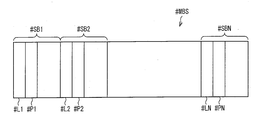
- the plurality of predetermined groups refers to, for example, a plurality of groups into which each sub-block is classified in the moving picture encoding apparatus that generates encoded data # 1. That is, in the moving picture encoding apparatus that generates the encoded data # 1, each of the subblocks SB1 to SBNs (Ns is the total number of subblocks belonging to the macroblock MB) belonging to a certain macroblock MB is determined as a predetermined classification method. Based on the group GP1 to GPM (M is the total number of groups into which the subblocks belonging to the macroblock MB are classified), the subblock SBn is classified into the group GPm. In this case, the group determination unit determines that the sub block SBn indicated by the sub block position information # 141a belongs to the group GPm based on the predetermined classification method, for example.
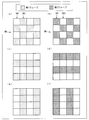
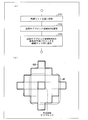
- each of the 16 sub-blocks included in the macroblock MB is classified into either the first group or the second group based on the classification method A.
- FIGS. 4C to 4D are diagrams showing cases where each sub-block is classified based on the classification method B, and FIGS. 4E to 4F.
- FIG. 10 is a diagram illustrating a case where each sub-block is classified based on a classification method C.
- each sub-block included in the macroblock MB has the first group or the first group so that the arrangement of the sub-blocks included in each group is a checkered flag.
- 4 may be classified into two groups, or as shown in FIGS. 4C to 4D, the sub-blocks included in each group may be classified so as to be adjacent only in the horizontal direction, As shown in FIGS. 4E to 4F, the sub-blocks included in each group may be classified so as to be adjacent only in the horizontal direction.
- the optimal classification method varies depending on the spatial correlation of the prediction parameters in the macroblock.
- the above classification method A is an effective classification method regardless of whether there is any spatial correlation in the vertical direction or the horizontal direction.
- the above classification method B and classification method C are effective.
- each sub-block has the first group or the first group or the sub-block according to the position in the macroblock MB. It is classified into one of the second groups.
- the group determination unit 41 refers to the sub-block position information # 141a, and the sub-block indicated by the sub-block position information # 141a is determined based on the classification method used in the video encoding device that generates the encoded data # 1. Which group of the first group and the second group belongs is determined.
- the sub-block SB1 belonging to the macroblock MB is second based on the classification method A, as shown in (a) to (b) of FIG.
- the group determination unit 41 refers to the sub-block position information # 141a based on the classification method A, so that the sub-block SB2 Are determined to belong to the first group, and the sub-block SB1 is determined to belong to the second group.
- the encoded data # 1 indicates which classification method is used for each macroblock. It is preferable to include a flag to indicate. By referring to such a flag, the group determination unit 41 can make a determination based on the classification method used in the video encoding device even when the classification method is different for each macroblock. it can.
- the number of sub-blocks included in the macroblock is 16, but the present invention is not limited to this (the same applies hereinafter).
- the subblock classification method in the macroblock MB is not limited to the above-described example, and other classification methods may be used.
- the classification method may be such that the number of subblocks belonging to the first subgroup and the number of subblocks belonging to the second subgroup are different from each other (the same applies hereinafter).
- the switch unit 42 Based on the group information # 41, the switch unit 42 converts the subblock encoded data # 141b, which is encoded data related to the subblock indicated by the subblock position information # 141a, to the first prediction parameter decoding unit 43 or the second The prediction parameter decoding unit 45 is transmitted to one of the parameter decoding units.
- the switch unit 42 performs the subblock encoded data.
- # 141b is transmitted to the first prediction parameter decoding unit 43, and when the group determination unit 41 determines that the subblock indicated by the subblock position information # 141a belongs to the second group, The sub-block encoded data # 141b is transmitted to the second prediction parameter decoding unit 45.
- the first prediction parameter decoding unit 43 decodes the sub-block encoded data # 141b, thereby generating the encoded data # 1 in the moving picture encoding apparatus, and the sub-block (indicated by the sub-block position information # 141a ( The prediction parameter # 43 used for prediction of the prediction target sub-block is decoded and output.
- the first prediction parameter decoding unit 43 first determines a prediction parameter used for prediction of the upper or left subblock of the prediction target subblock, and the decoded prediction parameter. Set to an estimate for the block.
- the first prediction parameter decoding unit 43 decodes the flag included in the sub-block encoded data # 141b.
- the estimated value is set as a prediction parameter for the prediction target sub-block, and the flag indicates that the estimated value is not used. Sets the prediction parameter decoded from the part other than the flag as the prediction parameter for the prediction target sub-block.
- the prediction parameter used for prediction may be referred to as the estimated value.
- the decoded prediction parameter # 43 is also supplied to the reduced set derivation unit 44.
- the reduced parameter deriving unit 44 is supplied with the prediction parameter # 43 decoded from each sub-block belonging to the first group.
- the reduced set deriving unit 44 accumulates the prediction parameter # 43 and generates a reduced prediction parameter set RS (hereinafter referred to as “reduced set RS”).
- the reduced set RS is a set including the prediction parameter # 43 decoded from each sub-block belonging to the first group. Further, the reduced set RS may include a prediction parameter other than the prediction parameter # 43.
- the reduced set derivation unit 44 When the same prediction parameter is decoded from a plurality of sub-blocks belonging to the first group, the reduced set derivation unit 44 includes only one of the same prediction parameter, A reduced set RS may be generated. In other words, the reduced set 44 may generate the reduced set RS so that the prediction parameters do not overlap. For example, when the prediction parameter PP1 is decoded from each of the subblocks SB1 to SB8 among the subblocks SB1 to SB16 belonging to the first group, and the prediction parameter PP2 is decoded from each of the subblocks SB9 to SB16, The reduced set derivation unit 44 generates a reduced set RS that includes one prediction parameter PP1 and one prediction parameter PP2.
- the prediction parameter is H.264.
- the generation operation of the reduced set RS by the reduced set derivation unit 44 will be described with reference to FIGS. 5 and 6A to 6C, taking the case of the intra prediction mode in the H.264 / MPEG-4 AVC standard as an example. To do.
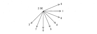
- FIG. 2 is a diagram showing an intra prediction mode (hereinafter referred to as “prediction mode”) used for intra prediction in the H.264 / MPEG-4 AVC standard, and an index assigned to each prediction mode.
- Each intra prediction mode represents a prediction direction used for intra prediction, and as shown in FIG.
- an 8-direction prediction mode (corresponding to indexes 0, 1, 3 to 8) and a DC prediction mode (corresponding to index 2) are used.
- the prediction mode specified by the index I is represented as the prediction mode I.
- a parameter set composed of the prediction modes 0 to 8 is called a basic parameter set.
- FIG. 6A is a flowchart illustrating a first example of the generation operation of the reduced set RS in the reduced set derivation unit 44.
- the reduced set derivation unit 44 initializes the reduced set RS by setting the reduced set RS to be empty (step S101).
- the reduced set deriving unit 44 adds the prediction parameter # 43 decoded from each sub-block belonging to the first group to the reduced set RS (step S102). For example, when the prediction mode 1, the prediction mode 6, and the prediction mode 8 are decoded from each sub-block belonging to the first group, the reduced set 44 includes the prediction mode 1, the prediction mode 6, and the prediction mode. 8 is added to the reduced set RS.
- the reduced set derivation unit 44 By performing the above operation, in the first example, the reduced set derivation unit 44 generates a reduced set RS configured by the prediction parameter # 43 decoded from each sub-block belonging to the first group. Can do.
- the prediction parameter selected for each sub-block belonging to the first group is highly likely to be an optimal prediction parameter for each sub-block belonging to the second group.
- the number of prediction modes included in the reduced set RS is smaller than the number of prediction parameters included in the basic parameter set.
- the moving picture encoding apparatus that generates the encoded data # 1 takes the configuration corresponding to the configuration of the present example, so that the encoded data # 1 having a small code amount can be obtained without sacrificing the encoding efficiency. Can be generated. Also, the moving picture decoding apparatus 1 can decode the encoded data # 1 generated in this way with a small code amount by adopting the configuration of this example.
- FIG. 6B is a flowchart illustrating a second example of the generation operation of the reduced set RS in the reduced set derivation unit 44.
- the reduced set derivation unit 44 initializes the reduced set RS by setting the reduced set RS to be empty (step S201).
- the reduced set derivation unit 44 adds the additional parameter set AS to the reduced set RS (step S202).
- the additional parameter set AS includes a prediction parameter that tends to be frequently used.
- the prediction mode specified by a smaller index tends to be used more frequently in intra prediction, so the prediction specified by the smaller index among indexes 0 to 8
- a mode is included.
- the additional parameter set AS is preferably configured to include a prediction mode 0 (vertical prediction mode), a prediction mode 1 (horizontal prediction mode), and a prediction mode 2 (DC prediction mode).
- the additional parameter set AS may be configured to include at least one prediction mode among the prediction mode 0, the prediction mode 1, and the prediction mode 2.
- the reduced set deriving unit 44 adds the prediction parameter # 43 decoded from each sub-block belonging to the first group to the reduced set RS (step S203).
- the reduced set derivation unit 44 does not add the prediction parameters already included in the reduced set RS of the prediction parameters # 43 to the reduced set RS in order to avoid duplication.
- the prediction parameter # 43 is the prediction mode 1 and the prediction mode 4
- the prediction mode 1 and the prediction mode 2 are already included in the reduced set RS
- the reduced set derivation unit 44 Need only add prediction mode 4 to the reduced set RS.
- the reduced set deriving unit 44 has the prediction parameter # 43 decoded from each sub-block belonging to the first group, the prediction mode included in the additional parameter set, and A reduced set RS can be generated.
- a reduced set RS composed of prediction parameters # 43 decoded from each sub-block belonging to the first group and a prediction mode that tends to be frequently used is obtained. Can be generated.
- the moving picture coding apparatus that generates the coded data # 1 and includes the reduced set derivation unit that operates as in this example is a code that has a smaller code amount of the prediction residual. Data # 1 can be generated. Also, the moving picture decoding apparatus 1 including the reduced set deriving unit 44 that operates as in the present example can decode the encoded data # 1 having a smaller code amount of such a prediction residual.
- FIG. 6C is a flowchart illustrating a third example of the generation operation of the reduced set RS in the reduced set derivation unit 44.
- the reduced set derivation unit 44 initializes the reduced set RS by setting the reduced set RS to be empty (step S301).
- the reduced set deriving unit 44 adds the prediction parameter # 43 decoded from each sub-block belonging to the first group to the reduced set RS (step S302).
- the reduced set deriving unit 44 determines whether or not log 2 (Np ⁇ 1) is an integer (step S303).
- Np is the number of prediction parameters included in the reduced set RS.
- the reduced set deriving unit 44 When log 2 (Np ⁇ 1) is an integer (Yes in step S303), the reduced set deriving unit 44 outputs the reduced set RS.
- the reduced set deriving unit 44 adds a predetermined prediction parameter to the reduced set (step S304), and performs the process of step S303 again.
- a predetermined prediction parameter for example, among the prediction modes 0 to 8 included in the basic parameter set, a prediction mode that is not included in the reduced set RS and has the smallest index is selected. Just do it.
- the reduced set deriving unit 44 adds a prediction mode that tends to be used more frequently in intra prediction to the reduced set in this step.
- the reduced set deriving unit 44 is a reduced set including the prediction parameter # 43 decoded from each sub-block belonging to the first group, and 2 n +1 A reduced set RS including n (n is an integer) prediction parameters can be generated.
- the reduced set deriving unit 44 can generate a reduced set RS with high compression efficiency when performing variable length coding by performing the above operation. Therefore, a moving image encoding apparatus that generates encoded data # 1 and that includes a reduced set derivation unit that operates as in this example generates encoded data # 1 with high compression efficiency. can do. In addition, the moving picture decoding apparatus 1 including the reduced set deriving unit 44 that operates as in the present example can decode such encoded data # 1 with high compression efficiency.
- the reduced set deriving unit 44 can generate the reduced set RS so as to include the predetermined prediction parameter.
- the reduced set RS including the prediction mode that tends to be used more frequently can be generated.
- the reduced set deriving unit 44 uses the prediction parameter # decoded from each sub-block belonging to the first group. Of 43, all kinds of prediction parameters except for overlapping ones are added to the reduced set RS. However, the prediction parameters decoded from the sub-blocks belonging to the first group may be configured to add only some types instead of all types.
- the appearance ratio of the prediction parameter is, for example, dividing the number of subblocks to which the prediction parameter is assigned among the subblocks belonging to the first group by the number of all subblocks belonging to the first group.
- the prediction parameter The appearance ratio of P can be defined by Npa / Nf.
- the appearance ratio can also be expressed as a percentage.
- prediction mode 0 is decoded for sub-blocks SB1, SB2, SB3, and SB4, prediction mode 1 is decoded for sub-blocks SB5 and SB6, and prediction mode 2 is decoded for sub-block SB7.
- prediction mode 3 is decoded for the block SB8 and the predetermined value is set to 40%, only the prediction mode 0 having the appearance ratio of 50% is added to the reduced set RS.
- the predetermined value is set to 20%, the prediction mode 0 in which the appearance ratio is 50% and the prediction mode 1 in which the appearance ratio is 25% are added to the reduced set RS. .
- the reduced set derivation unit 44 adds only the prediction parameter whose appearance ratio is higher than a predetermined value to the reduced set RS in the set of prediction parameters decoded from the sub-blocks belonging to the first group. Therefore, the above-described problem that it may be difficult to effectively reduce the code amount when the number of sub-blocks is large can be solved.
- the reduced set RS can be generated based on the prediction parameters belonging to the first group. More precisely, the reduced set RS can be generated based on at least one of the types of prediction parameters belonging to the first group or the appearance ratio of each prediction parameter belonging to the first group.
- the second prediction parameter decoding unit 45 includes, among the encoded data for each subblock included in the subblock encoded data # 141b, each subblock determined by the group determination unit 41 as belonging to the second group.
- the prediction parameter P used for prediction is decoded.
- the second prediction parameter decoding unit 45 refers to the information related to the prediction parameter included in the sub-block encoded data # 141b and related to the prediction parameter for each sub-block belonging to the second group. Then, the prediction parameter P used for prediction of each sub-block belonging to the second group is decoded.
- the decoded prediction parameter P is output as prediction parameter # 45.
- FIG. 7 is a flowchart showing an example of the flow of decoding processing in the second prediction parameter decoding unit 45.
- the second prediction parameter decoding unit 45 counts the number N of prediction parameters included in the reduced set RS (step S501).
- the second prediction parameter decoding unit 45 determines whether or not the number N of prediction parameters included in the reduced set RS is 1 (step S502).
- the second prediction parameter decoding unit 45 sets the only prediction parameter included in the reduced set as the prediction parameter P (step S503).
- the second prediction parameter decoding unit 45 derives a prediction parameter estimated value Q (step S504).
- the prediction parameter estimated value Q is a prediction parameter used for prediction of a subblock adjacent on the left or above the prediction target subblock.
- the prediction parameter used for block prediction may be the estimated value Q.
- the second prediction parameter decoding unit 45 decodes a flag indicating whether or not the prediction parameter to be decoded is the same as the prediction parameter estimated value Q, and substitutes the decoded value into the variable a.
- the prediction parameter estimation value Q is the same as any prediction parameter included in the reduced set RS
- the case where the value of the variable a is 1 corresponds to the case where the prediction parameter to be decoded is the same as the prediction parameter estimated value Q
- the case where the value of the variable a is not 1 The following description will be made assuming that the parameter is not the same as the predicted parameter estimated value Q.
- the second prediction parameter decoding unit 45 determines whether or not the value of the variable a is 1 (step S506).
- step S506 If the value of the variable a is 1 (Yes in step S506), the prediction parameter estimated value Q is set to the prediction parameter P (step S507).
- the second prediction parameter decoding unit 45 determines whether or not the number N of prediction parameters included in the reduced set RS is 2 (Step S506). S508).
- the second prediction parameter decoding unit 45 sets a prediction parameter that is included in the reduced set RS and does not match the prediction parameter estimated value Q as the prediction parameter P. (Step S509).
- the second prediction parameter decoding unit 45 decodes a bit string having a length of ceil (log 2 (N-1)) bits, and substitutes the decoded value into the variable b.
- ceil Is a ceiling function whose value is the smallest integer among the integers greater than or equal to the value in parentheses (the same applies hereinafter). Therefore, ceil strings Can also be expressed as a function that rounds up the value in the parentheses to an integer when the value in the parentheses is positive.
- the second prediction parameter decoding unit 45 calculates a prediction parameter having a (b + 1) th smallest index among prediction parameters that are included in the reduced set RS and do not match the prediction parameter estimation value Q.
- the prediction parameter P is set (step S511).
- the second prediction parameter decoding unit 45 is the first of the prediction parameters that are included in the reduced set RS and that do not match the prediction parameter estimated value Q.
- a prediction parameter having a small index is set as the prediction parameter P.
- led-out by the process demonstrated in step S504 is not the same as any prediction parameter included in the reduction set RS, it is included in the reduction set RS as the said prediction parameter estimation value Q.
- the prediction parameter with the smallest index may be used.
- a 2nd prediction parameter decoding part outputs the prediction parameter P decoded by the above processes as prediction parameter # 45.
- the video decoding device 1 uses the difference between the original image and the predicted image to determine which prediction parameter is selected from among a plurality of prediction parameters that specify the generation method of the predicted image for each prediction unit.
- An image decoding apparatus that decodes encoded data obtained by encoding together with selection information indicating a plurality of prediction units included in each of a plurality of unit regions constituting a prediction image, in the first group or Classification means (group determination unit 41) for classification into a second group is provided, and among the selection information, first selection information (subblock encoded data) that is selection information for each prediction unit belonging to the first group Reference is made to information relating to prediction parameters included in # 141b and relating to prediction parameters for each sub-block belonging to the first group)
- First selection means (first prediction parameter decoding unit 43) for selecting a prediction parameter for designating a prediction image generation method in each prediction unit belonging to the first group from a basic set of predetermined prediction parameters.
- second selection information that is selection information for each prediction unit belonging to the second group (information on prediction parameters included in sub-block encoded data # 141b, Prediction parameters for specifying a prediction image generation method in each prediction unit belonging to the second group are referred to by the first selection means (first prediction).
- first selection means first prediction
- a reduced set comprising at least some of the prediction parameters selected by the parameter decoding unit 43), Serial and a second selecting means for selecting from the reduction set RS consisting prediction parameter less than or equal to the number of prediction parameters included in the basic set (second prediction parameter decoding section 45), characterized in that it contains.
- the reduced set derivation unit 44 generates a reduced set RS for each sub-block, and the second prediction parameter decoding unit 45 based on the reduced set RS generated for each sub-block.
- the prediction parameter for the prediction target sub-block may be decoded.
- the reduced set deriving unit 44 can generate the reduced set RS by performing the following processing, as shown in FIG.
- Step S701 the reduced set derivation unit 44 initializes the reduced set RS by setting the reduced set RS to be empty.
- Step S702 the reduced set deriving unit 44 sets a region composed of sub-blocks around the prediction target sub-block as the neighboring sub-block region NSR.
- FIG. 8B is a diagram illustrating an example of the neighboring sub-block region NSR.
- the neighboring sub-block region NSR is, for example, a sub-block around the prediction target sub-block, and the distance from the prediction target sub-block is 1 to 3 in units of sub-blocks. It can consist of sub-blocks that are within the city distance.
- the urban area distance is a distance defined by the sum of absolute values of differences between coordinates with respect to coordinates between two points.
- the neighboring sub-block region NSR may generally include a sub-block belonging to a macro block other than the macro block to which the prediction target sub-block belongs.
- Step S703 the reduced set deriving unit 44 adds a decoded prediction parameter among the prediction parameters for each subblock included in the neighboring subblock region NSR to the reduced set RS.
- the reduced set derivation unit 44 sets the same parameter to 1 for the reduced set RS. Add only one.
- the reduced set deriving unit 44 can generate a reduced set RS for each macroblock.
- the 2nd prediction parameter decoding part 45 can decode the prediction parameter with respect to a prediction object subblock based on the reduction
- a prediction parameter for a prediction target sub-block has a correlation with a prediction parameter for sub-blocks around the prediction target sub-block. Therefore, the prediction parameter included in the reduced set RS generated by the above processing is highly likely to include the most appropriate prediction parameter in the prediction of the sub-blocks belonging to the second group. In addition, the number of prediction parameters included in the reduced set RS generated by the above processing is generally smaller than the number of prediction parameters that can be selected for the first group.
- the moving image encoding apparatus that generates encoded data # 1 generates encoded data # 1 with a small code amount without sacrificing encoding efficiency by adopting a configuration corresponding to the above configuration. can do. Further, the moving picture decoding apparatus 1 can decode the encoded data # 1 generated in such a manner with a small code amount by adopting the above configuration.
- the second prediction parameter decoding unit 45 selects, for example, a prediction parameter from the basic parameter set. What is necessary is just composition.
- the reduced set 44 in the present configuration example is configured to derive the reduced set RS by substantially the same process as described in (Generated Example 1 of Reduced Set RS) to (Generated Example 4 of Reduced Set RS). It is good. However, in this case, “first group” in (reduction set RS generation example 1) to (reduction set RS generation example 4) is read as “neighboring sub-block region NSR” in this configuration example.
- the reduced set RS is used for the second group, but the present invention is not limited to this.
- the above-described processing can be applied to all subblocks in the macroblock. That is, it is good also as a structure which decodes a prediction parameter based on the reduction
- the moving picture encoding apparatus that generates the encoded data # 1 can further reduce the amount of prediction parameter codes for all the sub-blocks in the macroblock by adopting a configuration corresponding to the above configuration. Therefore, the moving picture encoding apparatus can generate encoded data # 1 with a smaller code amount. Moreover, the moving image decoding apparatus 1 can decode the encoded data # 1 generated as described above by adopting the above configuration.
- the predicted image generation unit 145 determines the predicted pixel value of each pixel (prediction target pixel) in the predicted image # 145 (prediction target sub-block) according to the prediction direction (prediction mode) indicated by the prediction parameter # 144, for example, as follows: Generate as follows. In the following description, the case where the prediction parameter # 144 is one of the prediction modes 0 to 8 shown in FIG. 5 will be described as an example.
- the predicted image generation unit 145 performs the following operation after assigning the prediction mode indicated by the prediction parameter # 144 to the prediction target pixel.
- the predicted image generation unit 145 starts on the virtual line segment that faces the reverse direction of the prediction direction starting from the pixel position of the prediction target pixel.
- the pixel value of the pixel closest to the pixel (hereinafter referred to as the nearest pixel) is set as the pixel value of the prediction target pixel.
- the pixel value of the prediction target pixel may be a value calculated using the pixel value of the nearest pixel and the pixel values of the pixels around the nearest pixel.
- the sub-block adjacent to the upper side of the prediction target sub-block (hereinafter referred to as the upper sub-block) and the sub-block adjacent to the left side (hereinafter referred to as the left sub-block) Is already decoded, the pixel value of the pixel in the lowermost column of the upper sub-block and the pixel value of the pixel in the rightmost column of the left sub-block are used as the pixel value of the prediction target pixel.
- the assigned prediction mode is prediction mode 2 and the upper sub-block has been decoded and the left sub-block has not been decoded
- the pixel value of the pixel in the bottom row of the upper sub-block, and , The average value of the pixel values of the pixels in the rightmost column in the subblock to the left of the prediction target subblock and closest to the prediction target subblock (hereinafter referred to as the left nearest subblock), The pixel value of the prediction target pixel is used.
- the sub-block above the prediction target sub-block is The average value of the pixel value of the pixel in the lowermost column in the subblock closest to the prediction target subblock (hereinafter referred to as the upper nearest subblock) and the pixel value of the pixel in the rightmost column of the left subblock, The pixel value of the prediction target pixel is used.
- the assigned prediction mode is prediction mode 2 and neither the upper subblock nor the left subblock has been decoded
- the pixel value of the pixel in the bottom row of the uppermost subblock The average value of the pixel values of the rightmost column of the left nearest subblock is set as the pixel value of the prediction target pixel.
- FIG. 9 is a diagram showing each pixel (prediction target pixel) of a prediction target sub-block that is 4 ⁇ 4 pixels and pixels (reference pixels) around the prediction target sub-block.
- the prediction target pixels are denoted by symbols a to p
- the reference pixels are denoted by symbols A to M
- the pixel value of the pixel X (X is any of a to p or A to M) is set to X It will be expressed as Further, it is assumed that the reference pixels A to M have all been decoded.
- ave Indicates that an element included in parentheses is averaged.
- “>>” represents a right shift operation, and for any positive integer x, s, the value of x >> s is equal to the value obtained by rounding down the decimal part of x ⁇ (2 ⁇ s).
- the predicted image generation unit 145 can calculate the pixel values a to p by a similar method for prediction modes other than the above prediction modes.
- the second prediction parameter decoding unit 45 may be configured to switch whether to use the reduced set RS when decoding the prediction parameter # 45 according to the flag included in the encoded data # 1. .
- the second prediction parameter decoding unit 45 decodes the prediction parameter # 45 using the reduced set RS
- the prediction parameter # 45 may be decoded using the basic parameter set instead of the reduced set RS.
- the second prediction parameter decoding unit 45 may be configured to switch whether to use the reduced set RS when decoding the prediction parameter # 45 according to the number of subblocks included in the macroblock. .
- the prediction parameter # 45 is decoded using the reduced set RS, and the number of subblocks included in the macroblock is 16. If the number is less than the number, the prediction parameter # 45 may be decoded using the basic parameter set instead of the reduced set RS.
- the prediction parameter decoding unit 144 sets, as the basic parameter set, a parameter set that emphasizes the horizontal direction as shown in FIG. 16A or a parameter that emphasizes the vertical direction as shown in FIG. It is good also as a structure which uses a set.
- the prediction parameter decoding unit 144 sets the horizontal direction as shown in FIG.
- a parameter set that emphasizes the vertical direction as shown in FIG. 16B is used as the basic parameter set. It can be configured.
- the second prediction parameter decoding is performed.
- the unit 45 decodes the prediction parameter # 45 using the reduced set RS, and when the parameter set shown in FIG. 5 is selected as the basic parameter set, the second prediction parameter decoding unit 45 replaces the reduced set RS.
- the prediction parameter # 45 may be decoded using the basic parameter set.
- the reduced set RS can be used according to the characteristics of the image in the macroblock.
- FIG. 10 is a block diagram illustrating a configuration of the moving image encoding device 2.
- the moving image encoding device 2 includes a header information determination unit 21, a header information encoding unit 22, an MB setting unit 23, an MB encoding unit 24, a variable length code multiplexing 25, and an MB decoding unit 26. And a frame memory 27.
- the video encoding device 2 is a device that generates and outputs encoded data # 1 by encoding the input image # 100, in brief.
- the header information determination unit 21 determines header information based on the input image # 100. The determined header information is output as header information # 21.
- the header information # 21 includes the image size of the input image # 100.
- the header information # 21 is input to the MB setting unit 23 and supplied to the header information encoding unit 22.
- the header information encoding unit 22 encodes header information # 21 and outputs encoded header information # 22.
- the encoded header information # 22 is supplied to the variable length code multiplexer 25.
- the MB setting unit 23 divides the input image # 100 into a plurality of macro blocks based on the header information # 21, and outputs a macro block image # 23 related to each macro block.
- the macro block image # 23 is sequentially supplied to the MB encoding unit 24.
- the MB encoding unit 24 encodes sequentially input macroblock images # 23 to generate MB encoded data # 24.
- the generated MB encoded data # 24 is supplied to the variable length code multiplexer 25. Since the configuration of the MB encoding unit 24 will be described later, the description thereof is omitted here.
- variable length code multiplexer 25 generates encoded data # 1 by multiplexing the encoded header information # 22 and the MB encoded data # 24, and outputs the encoded data # 1.
- the MB decoding unit 26 generates and outputs a decoded image # 26 corresponding to each macroblock by sequentially decoding the MB encoded data # 24 corresponding to each input macroblock.
- the decoded image # 26 is supplied to the frame memory 27.
- the input decoded image # 26 is recorded in the frame memory 27.
- decoded images corresponding to all macroblocks that precede the macroblock in the raster scan order are recorded in the frame memory.
- FIG. 11 is a block diagram showing a configuration of the MB encoding unit 24.
- the MB encoding unit 24 includes a sub-block dividing unit 241, a prediction parameter determining unit 242, a prediction parameter encoding unit 243, a prediction residual generation unit # 244, a transform coefficient encoding unit 245, a prediction residual.
- a difference decoding unit 246, a sub-block decoded image generation unit 247, a predicted image generation unit 248, and an MB encoded data generation unit 249 are provided.
- the subblock division unit 241 divides the macroblock image # 23 into a plurality of subblocks, subblock position information # 241a indicating the position of each subblock constituting the macroblock in the macroblock, and the subblock Sub-block image # 241b, which is image data related to the sub-block indicated by position information # 241a, is sequentially output in a predetermined order.
- the sub-block dividing unit 241 outputs sub-block position information # 241a and sub-block image # 241b related to sub-blocks belonging to the first group described later, and then outputs sub-blocks related to sub-blocks belonging to the second group described later. It is preferable that the position information # 241a and the sub-block image # 241b are output. For example, it is preferable that the sub blocks belonging to the first group are scanned in the raster scan order, and then the sub blocks belonging to the second group are scanned in the raster scan order.
- the prediction parameter determination unit 242 determines and outputs a prediction parameter # 242 used to generate a prediction image related to the subblock indicated by the subblock position information # 241a. Further, the prediction parameter encoding unit 243 encodes the prediction parameter # 242 and outputs the encoded prediction parameter # 243. Since the configuration of the prediction parameter determination unit 242 and the prediction parameter encoding unit 243 will be described later, description thereof is omitted here.
- the prediction residual generation unit 244 identifies a subblock to be predicted based on the subblock position information # 241a, and the prediction generated by the subblock image # 241b and the prediction image generation unit 248 in the subblock. A prediction residual # 244 that is a difference image from the image # 248 is generated.
- the transform coefficient coding unit 245 generates a transform coefficient of the prediction residual # 244 by applying frequency transform having the same size as the sub-block size to the prediction residual # 244.
- the transform coefficient encoding unit 245 quantizes the transform coefficient to generate a quantized transform coefficient # 245a, and then applies a variable length coding method such as CABAC or CAVLC to the quantized transform coefficient # 245a. This is applied to generate a variable length code, and the variable length code is output as encoded data # 245b.
- a variable length coding method such as CABAC or CAVLC
- the prediction residual decoding unit 246 generates and outputs a decoding residual # 246 by inversely quantizing the quantized transform coefficient # 245a and then applying inverse transform of frequency transform (inverse frequency transform).
- the above processing by the prediction residual generation unit 244, the transform coefficient encoding unit 245, and the prediction residual decoding unit 246 does not limit the present invention.
- the transform coefficient coding unit 245 may omit the frequency transform and directly quantize the prediction residual.
- the sub-block decoded image generation unit 247 generates and outputs a sub-block decoded image # 247 by adding the predicted image # 248 and the decoded residual # 246.
- the predicted image generation unit 248 generates and outputs a predicted image # 248 corresponding to the prediction target sub-block based on the prediction parameter # 242, the decoded image # 27, and the sub-block decoded image # 247.
- the MB encoded data generation unit 249 accumulates the encoded data # 245b for each subblock and the encoded prediction parameter # 243 for each subblock, and integrates the encoded data in units of macroblocks.
- prediction parameter determination unit 242 and the prediction parameter encoding unit 243 will be described with reference to different drawings.
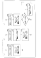
- FIG. 12 is a block diagram illustrating a configuration of the prediction parameter determination unit 242.
- the prediction parameter determination unit 242 includes a group determination unit 51, a switch unit 52, a first prediction parameter determination unit 53, a reduced set derivation unit 54, and a second prediction parameter determination unit 55. .
- the group determination unit 51 classifies the sub-block indicated by the sub-block position information # 241a into one of a plurality of groups, and outputs group information # 51 indicating the classification result to the switch unit 52.
- the group determination unit 51 can classify each sub-block into either the first group or the second group, for example, as already described with reference to FIGS.
- the group determination unit 51 may classify each sub-block into any one of a plurality of groups using a different classification method for each macroblock. For example, as shown in FIGS. 4A to 4B, the sub-blocks constituting the macro block MB1 are classified into two groups, and the sub-blocks constituting the macro block MB2 different from the macro block MB1 are classified. As shown in (c) to (d) of FIG. 4, it may be configured to be classified into two groups. As described above, when any one of a plurality of classification methods is used for each macroblock, the group determination unit 51 may output a flag indicating which classification method is used. preferable. By transmitting the flag to the moving picture decoding apparatus that decodes the encoded data # 1, the moving picture decoding apparatus can identify which classification method is used in the group determination unit 51.
- the switch unit 52 converts the subblock encoded data # 241b, which is encoded data related to the subblock indicated by the subblock position information # 241a, to the first prediction parameter determination unit 53 or the second This is transmitted to one of the prediction parameter determination units 55.
- the switch unit 52 converts the subblock encoded data # 241b into the first block. 1 is transmitted to the prediction parameter determination unit 53.
- the group determination unit 51 determines that the sub-block indicated by the sub-block position information # 241a is classified into the second group, the sub-block encoded data # 241b Is transmitted to the second prediction parameter determination unit 45.
- the first prediction parameter determination unit 53 is used to generate a prediction image for each subblock belonging to the first group based on the decoded image # 27, the subblock decoded image # 247, and the subblock encoded data # 241b.
- the prediction parameter # 53 is determined (selected) and output.
- the prediction parameter # 53 is also supplied to the reduced set derivation unit 54.
- the prediction parameter is H.264.
- the first prediction parameter determination unit 53 sets the basic parameter set shown in FIG. 5 described above for each sub-block belonging to the first group. One of the prediction modes is selected and output.
- the specific method for determining the prediction parameter # 53 in the first prediction parameter determination unit 53 does not limit the present invention.
- the first prediction parameter determination unit 53 includes each sub-group belonging to the first group.
- the prediction parameter # 53 may be determined for the block so that the difference between the predicted image and the input image # 100 in the sub-block is minimized.
- the first prediction parameter determination unit 53 has the largest difference between the prediction image generated using the prediction mode 1 and the input image # 100 in the basic parameter set for the sub-block SB1 belonging to the first group.
- the prediction mode 1 is selected for the sub-block SB1
- the sub-block SB2 belonging to the first group is generated using the prediction mode 2 in the basic parameter set.
- the prediction mode 2 may be selected for the sub-block SB2.
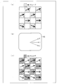
- FIG. 13 is a figure which shows the example of the prediction mode which the 1st prediction parameter determination part 53 selected with respect to each subblock which belongs to a 1st group among each subblock which comprises macroblock MB. is there.
- the first prediction parameter determination unit 53 determines which one of prediction mode 1, prediction mode 6, and prediction mode 8 for each sub-block belonging to the first group. The prediction mode is selected.
- the prediction mode 1, the prediction mode 6, and the prediction mode 8 are supplied to the reduced set derivation unit 54 as the prediction parameter # 53.
- the reduced set derivation unit 54 is supplied with the prediction parameter # 53 regarding each sub-block belonging to the first group.
- the configuration of the reduced set derivation unit 54 is the same as that of the reduced set derivation unit 44 already described. That is, the reduced set derivation unit 54 generates a reduced set RS using the prediction parameter # 53.
- the generation method of the reduced set RS in the reduced set derivation unit 54 is the same as the generation method of the reduced set RS in the reduced set derivation unit 44 already described.
- the reduced set derivation unit 54 when a plurality of generation methods are selectively used, the reduced set derivation unit 54 preferably outputs a flag indicating which generation method has been selected. By transmitting the flag to the video decoding device that decodes the encoded data # 1, the video decoding device can identify which generation method is used in the reduced set deriving unit 54.
- FIG. 13B is a diagram illustrating an example of a reduced set RS generated by the reduced set derivation unit 54 when each prediction mode illustrated in FIG. 13A is supplied as the prediction parameter # 53. .
- the reduced set RS includes a prediction mode 1, a prediction mode 1, and a prediction mode 6.
- the second prediction parameter determination unit 55 selects and outputs a prediction parameter # 55 used for generating a prediction image related to each sub-block belonging to the second group from the prediction parameters included in the reduced set RS.
- the specific method for determining the prediction parameter # 55 in the second prediction parameter determination unit 55 is not limited to the present invention.
- the second prediction parameter determination unit 55 applies to each sub-block belonging to the second group.
- the prediction parameter # 55 that can most appropriately generate the prediction image in the sub-block may be selected from the prediction parameters included in the reduced set RS.
- FIG. 13C shows the second prediction parameter determination unit 55 shown in FIG. 13B for each subblock belonging to the second group among the subblocks constituting the macroblock MB. It is a figure which shows the example of the prediction mode selected from reduction set RS. As shown in FIG. 13C, for each sub-block belonging to the second block, prediction mode 1, prediction mode 6 or prediction mode included in the reduced set RS shown in FIG. 13B. Any one of 8 prediction modes is selected.
- the prediction parameter selected for each sub-block belonging to the first group is highly likely to be an optimal prediction parameter for each sub-block belonging to the second group.
- the second prediction parameter determination unit 55 selects the prediction parameter # 55 for each sub-block belonging to the second group from the prediction parameters included in the reduced set RS, so that the reduced set RS is not used. As compared with the above, the code amount of the prediction parameter # 55 can be reduced.
- the second group is composed of 8 sub-blocks, 3 ⁇ for each macroblock is obtained by using the reduced set RS as compared with the case where the reduced set RS is not used.
- the number of prediction parameters that can be selected for each sub-block belonging to the first group is included in Nfs and the reduced set RS.
- the number of prediction parameters is Nrs and the number of sub-blocks included in the second group is Ngs
- the use of the reduced set RS makes it possible to obtain Ngs for each macroblock as compared with the case where the reduced set RS is not used.
- the code amount of ⁇ (ceil (log 2 (Nfs ⁇ 1)) ⁇ ceil (log 2 (Nrs ⁇ 1))) bits can be reduced.
- the reduced set derivation unit 54 generates a reduced set RS for each sub-block, and the second prediction parameter determination unit 55 based on the reduced set RS generated for each sub-block.
- the prediction parameter for the prediction target sub-block may be determined.
- the reduced set deriving unit 54 operates in the same manner as the operation of the reduced set deriving unit 44 described in (Step S701) to (Step S703) of (another configuration example of the prediction parameter decoding unit 144).
- the configuration may be such that However, the decoded prediction parameters in (step S701) to (step S703) of (another configuration example of the prediction parameter decoding unit 144) correspond to the encoded prediction parameters in this example.
- the reduced set deriving unit 54 can generate a reduced set RS for each sub-block.
- the 2nd prediction parameter determination part 55 can determine the prediction parameter with respect to a prediction object subblock based on the reduction
- a prediction parameter for a prediction target sub-block has a correlation with a prediction parameter for sub-blocks around the prediction target sub-block. Therefore, the prediction parameter included in the reduced set RS generated by the above processing is highly likely to include the most appropriate prediction parameter in the prediction of the sub-blocks belonging to the second group. In addition, the number of prediction parameters included in the reduced set RS generated by the above processing is generally smaller than the number of prediction parameters that can be selected for the first group.
- the moving picture encoding apparatus 1 can generate encoded data # 1 with a small code amount without sacrificing encoding efficiency by adopting the above configuration.
- the second prediction parameter determination unit 55 selects, for example, a prediction parameter from the basic parameter set. What is necessary is just to make it a structure.
- the reduced set 54 in the present configuration example is configured to derive the reduced set RS by substantially the same process as described in (Generated Example 1 of Reduced Set RS) to (Generated Example 4 of Reduced Set RS). It is good. However, in this case, “first group” in (reduction set RS generation example 1) to (reduction set RS generation example 4) is read as “neighboring sub-block region NSR” in this configuration example.
- the reduced set RS is used for the second group, but the present invention is not limited to this.
- the above-described processing can be applied to all subblocks in the macroblock. That is, it is good also as a structure which determines a prediction parameter based on the reduction
- the moving image encoding apparatus 1 can generate encoded data # 1 with a smaller code amount by adopting the above configuration.
- FIG. 14 is a block diagram illustrating a configuration of the prediction parameter encoding unit 243.
- the prediction parameter encoding unit 243 includes a group determination unit 61, a switch unit 62, a first prediction parameter encoding unit 63, a reduced set derivation unit 64, and a second prediction parameter encoding unit 65. I have.
- the group determination unit 61 has substantially the same configuration as the group determination unit 51 already described. That is, the group determination unit 61 classifies the sub-block indicated by the sub-block position information # 241a into one of a plurality of predetermined groups, and sets the group information # 61 indicating the classification result to the switch unit 62. Output. Note that the group determination unit 61 may classify each sub-block into one of a plurality of predetermined groups using the same classification method as that used in the group determination unit 51.
- the switch unit 62 sets the prediction parameter # 242 related to the subblock indicated by the subblock position information # 241a to the first prediction parameter encoding unit 63 or the second prediction parameter encoding unit 65. Of these, it is transmitted to one of the parameter encoding units.
- the switch unit 62 sets the prediction parameter # 242 as the first prediction parameter.
- the prediction parameter # 242 is transmitted to the encoding unit 63 and the reduced set derivation unit 64. Is transmitted to the second prediction parameter encoding unit 65.
- the first prediction parameter encoding unit 63 generates and outputs the encoded prediction parameter # 63 by encoding the prediction parameter # 242 related to each sub-block belonging to the first group.
- the first prediction parameter encoding unit 63 first sets the prediction parameter selected for the sub-blocks around each sub-block belonging to the first group to the estimated value for the sub-block.
- the first prediction parameter encoding unit 63 encodes a flag indicating whether or not the prediction parameter selected for the subblock is different from the estimated value, and is further selected for the subblock. If the predicted parameter is different from the estimated value, the predicted parameter is encoded.
- the prediction parameter of each sub-block when the prediction parameter of each sub-block is selected from the basic parameter set, the prediction parameter can be expressed by a 1-bit or 4-bit code including a flag.
- the first prediction parameter encoding unit 63 may be configured to encode the prediction parameter # 242 regarding each sub-block belonging to the first group as it is.
- the reduced set derivation unit 64 generates a reduced set RS using the prediction parameter # 242 related to the sub-blocks belonging to the first group.
- the generation method of the reduced set RS in the reduced set derivation unit 64 is the same as the generation method of the reduced set RS in the reduced set derivation unit 44 described above, and thus the description thereof is omitted here.
- the second prediction parameter encoding unit 65 encodes a prediction parameter included in the reduced set RS, that is, a prediction parameter selected for each sub-block belonging to the second group, thereby encoding encoded parameter # 65. Is generated and output.
- the second prediction parameter encoding unit 65 first sets the prediction parameter selected for the sub-blocks around each sub-block belonging to the second group to the estimated value for the sub-block.
- the second prediction parameter encoding unit 65 encodes a flag indicating whether or not the prediction parameter selected for the subblock is different from the estimated value, and further selects the flag for the subblock. If the predicted parameter is different from the estimated value, the predicted parameter is encoded.
- Nrs 2
- the encoding process of the second prediction parameter is terminated.
- the prediction parameters included in the reduced set can be represented by a code of ceil (log 2 (Nrs-1)) bits.
- the number Nrs of prediction parameters included in the reduced set RS is generally smaller than the number of prediction parameters that can be selected for the first group.
- the prediction parameter selected for each subblock belonging to the second group can be encoded with a smaller code amount.
- the second prediction parameter encoding unit 65 may be configured to encode the prediction parameter selected for each sub-block belonging to the second group as it is.
- Video Encoding Device 2 ⁇ Additional Notes on Video Encoding Device>
- the video encoding device 2 according to the present invention has been described above, but the present invention is not limited to the above configuration.
- the second prediction parameter determination unit 55 determines whether or not to use the reduced set RS according to the magnitude of the spatial correlation in the macroblock of the prediction parameter, and when the spatial correlation is small, the reduced set It is good also as a structure which determines prediction parameter # 55, without utilizing RS.
- the moving image encoding device 2 encodes a flag indicating that the reduced set RS is not used. It is preferable to adopt a configuration for transmitting to the video decoding device.
- the prediction parameter # 55 can be determined without using the reduced set RS, so that the processing amount for determining the prediction parameter is suppressed. be able to.
- the second prediction parameter determination unit 55 may be configured to switch whether to use the reduced set RS when determining the prediction parameter # 55 according to the number of subblocks included in the macroblock. .
- the prediction parameter # 55 is determined using the reduced set RS, and the number of subblocks included in the macroblock is 16.
- the prediction parameter # 45 may be determined using the basic parameter set instead of the reduced set RS.
- the prediction parameter # 55 can be determined without using the reduced set RS, so that the processing amount for determining the prediction parameter is suppressed. Can do.
- the prediction parameter determination unit 242 sets a basic parameter set as shown in FIG. 16A as a basic parameter set according to the characteristics of the image in the macroblock, or FIG. 16B. It is also possible to use a parameter set that emphasizes the vertical direction as shown in FIG.
- the prediction parameter determination unit 242 uses a parameter set that emphasizes the horizontal direction as shown in FIG. 16A as the basic parameter set when there is a horizontal edge in the macroblock.
- a parameter set that emphasizes the vertical direction as shown in FIG. 16B it is possible to use a parameter set that emphasizes the vertical direction as shown in FIG. 16B as the basic parameter set. It is.
- the second prediction parameter determining unit 55 when a plurality of basic parameter sets are selectively used and the parameter set shown in FIG. 16A or 16B is selected as the basic parameter set, the second prediction parameter determining unit 55 When the prediction parameter # 55 is determined using the reduced set RS and the parameter set shown in FIG. 5 is selected as the basic parameter set, the second prediction parameter determining unit 55 replaces the reduced set RS with The prediction parameter # 55 may be decoded using the basic parameter set.
- the reduced set RS can be used according to the characteristics of the image in the macroblock, so that the code amount of the prediction parameter can be effectively reduced.
- FIG. 15 is a diagram showing a bit stream structure of bit stream #MBS for each macro block of encoded data # 1.
- the bitstream #MBS is subblock information # SB1 to #SBN which is information on subblocks SB1 to SBN (where N is the number of subblocks in the macroblock) included in the macroblock. (Where N is the number of sub-blocks in the macroblock).
- each sub-block information #SBn (1 ⁇ n ⁇ N) corresponds to sub-block position information #Ln, which is information indicating the position of sub-block SBn in the macroblock, and sub-block SBn.
- prediction parameter information #Pn indicating the attached prediction parameter.
- the sub-block position information #Ln is information that is referred to in order to identify the position of the sub-block SBn in the macro block in the video decoding device that decodes the encoded data # 1.
- the sub-block position information #Ln is information that is referred to in order to classify the sub-blocks SBn into groups.
- Prediction parameter information #Pn is information for specifying the prediction parameter associated with the sub-block SBn in the video decoding device that decodes the encoded data # 1.
- the prediction parameter information #Pn is information indicating one of the prediction parameters that can be selected for the group to which the sub-block SBn belongs.
- the prediction parameter information # Pn is information indicating one of the prediction modes 0 to 8 included in the basic parameter set.
- the prediction parameter information #Pn is information indicating any prediction parameter among the prediction parameters included in the reduced set RS.
- the prediction parameter information #Pn includes ceil (log 2 (N-1)) represented by a bit code.
- N is the number of prediction parameters that can be selected for the group to which the sub-block SBn belongs.
- the number of prediction parameters included in the reduced set RS is smaller than the number of prediction parameters that can be selected for the first group. Therefore, the code amount of the prediction parameter included in the encoded data # 1 is small compared to the case where the reduced set RS is not used.
- the code of the prediction parameter information #Pn The amount is less ceil (log 2 (Nfs ⁇ 1)) ⁇ ceil (log 2 (Nrs ⁇ 1)) bits than when the reduced set RS is not used.
- Nfs is the number of prediction parameters that can be selected for each sub-block belonging to the first group
- Nrs is the number of prediction parameters included in the reduced set RS.
- the code amount of the encoded data # 1 can be reduced by using the reduced set RS.
- the sub-block position information #Ln may not be included in the encoded data # 1.
- the position of the sub-block can be determined based on information about what number of sub-blocks in the encoded data # 1.
- motion compensation prediction In motion compensation prediction, the position of a region on a decoded image used for prediction of a prediction target sub-block is expressed using a prediction parameter called a motion vector.
- the motion vector is selected from a prediction parameter set in which the number of elements depends on the image size and accuracy (interpolation accuracy). For example, when the image width (the number of pixels in the horizontal direction) is W, the height (the number of pixels in the vertical direction) is H, and the interpolation accuracy is 0.25 pixels, the motion vector V is defined by the following equation: Prediction parameter set S.
- V ((N / 4), (M / 4))
- N and M are integers satisfying 0 ⁇ N ⁇ 4W and 0 ⁇ M ⁇ 4H.
- the first prediction parameter determination unit 53 may determine and assign a motion vector for each sub-block belonging to the first group, for example. Further, the first parameter decoding unit 43 can decode a motion vector for each sub-block belonging to the first group.
- the reduced set derivation units 44 and 54 can generate a reduced set RS from the motion vector assigned to each sub-block belonging to the first group. Further, as already described, the reduced set deriving units 44 and 54 may generate the reduced set RS from the motion vectors assigned to the subblocks around the prediction target subblock.
- the same operation as when the prediction parameter is in the prediction mode is performed, so that the prediction parameter included in the encoded data # 1
- the amount of codes can be reduced.
- the reduced set derivation units 44 and 54 when the prediction parameter is a motion vector, the reduced set derivation units 44 and 54, for example, set the norm of the difference vector from the motion vector allocated to the subblocks around the prediction target subblock to be equal to or less than a certain value. Such a motion vector may be added to the reduced set RS.
- the prediction parameter set includes a large number of prediction vectors.
- the number of motion vectors accumulated in the reduced set RS is limited to the number of subblocks belonging to the first group or the number of subblocks around the prediction target subblock. For example, even when subblocks included in the neighboring subblock region NSR shown in FIG. 8B are used, the number of motion vectors stored in the reduced set RS is at most 24.
- the reduced set RS is sufficient. Since a number of motion vectors are not accumulated, the prediction accuracy may be reduced and the code amount of residual data may be increased.
- the code amount of the residual data is increased by adding to the reduced set RS a motion vector such that the norm of the difference vector with respect to the motion vector assigned to the sub-blocks around the prediction target sub-block is equal to or less than a certain value. Therefore, it is possible to reduce the code amount of the prediction parameter.
- the luminance of a prediction target sub-block is predicted using a value obtained by multiplying the luminance of each of a plurality of reference pictures referenced by the prediction target sub-block for motion compensation prediction by a weighting coefficient.
- the present invention can also be applied to the case where the prediction parameter is the weighting factor.
- the reduced set derivation units 44 and 54 may be configured to generate the reduced set RS from the weighting factors assigned to the subblocks around the prediction target subblock.
- each value taken by the weighting factor is associated with a plurality of representative values whose total number is determined in advance, and the representative value is used as a prediction parameter. It is good also as a structure.
- the value W of the weighting factor can take all real values (or values with a predetermined number of digits) satisfying 0 ⁇ W ⁇ 1, (n / X) ⁇ Wn ⁇ ((n + 1) ) / X) all weight coefficient values Wn may be associated with the representative value w, and the representative value w may be used as a prediction parameter.
- X is a natural number
- n is an integer that satisfies 0 ⁇ n ⁇ X ⁇ 1.
- all real values satisfying 0 ⁇ W ⁇ 1 can be mapped to a set of representative values Wn whose total number is X.
- what is necessary is just to set the specific value of X so that the code amount of coding data may become smaller, for example.
- the code amount of the encoded data can be reduced as compared with the case where the weighting factor is directly used as the prediction parameter.
- An image encoding device in an image encoding device that encodes a difference between an input image and a predicted image, divides the predicted image into a plurality of unit regions and includes a plurality of prediction units included in each unit region.
- a first selection means for selecting a prediction parameter for specifying a prediction image generation method in each prediction unit belonging to the second group, Select from a reduced set that includes prediction parameters that are less than or equal to the number of prediction parameters included in the basic set. For each prediction unit belonging to the second selection means and the first group, which prediction parameter the first selection means has selected, and for each prediction unit belonging to the second group, And prediction parameter encoding means for encoding which prediction parameter is selected by the second selection means.
- a prediction parameter that specifies a method of generating a predicted image in each prediction unit belonging to the second group is included in the same unit region as the second group. From a prediction parameter that is a reduced set that includes at least a part of the prediction parameters selected by the first selection unit for each prediction unit belonging to the first group, and is equal to or less than the number of prediction parameters included in the basic set. The reduction set is selected, and the prediction parameter selected by the second selection unit is encoded.
- the prediction parameter for each prediction unit is generally correlated with the prediction parameter for the prediction unit located in the vicinity of the prediction unit, the prediction parameter selected for each prediction unit belonging to the first group. Is likely to be an appropriate prediction parameter for each prediction unit belonging to the second group. That is, for each prediction unit belonging to the second group, there is a high possibility that the prediction parameter selected from the reduced set is an appropriate prediction parameter. Therefore, according to the above configuration, the prediction parameter can be encoded without reducing the encoding efficiency.
- the reduced set is a reduced set including at least a part of the prediction parameters selected by the first selection unit, and is equal to or less than the number of prediction parameters included in the basic set. Since the set includes prediction parameters, it is possible to reduce the code amount of information indicating which prediction parameter is selected for each prediction unit belonging to the second group.
- the reduced set includes only all prediction parameters that are prediction parameters selected by the first selection unit and are different from each other.
- the number of prediction parameters included in the reduced set can be reduced, the amount of codes can be further reduced. More specifically, since the prediction parameters generally have a spatial correlation, there is a bias in the optimal prediction parameter distribution for each prediction unit in a specific region. Therefore, there is a high probability that only a part of various prediction parameters included in the basic set is used in a specific region. Therefore, the set of prediction parameters selected by the first selection means in a specific region often has fewer elements than the set of prediction parameters included in the basic set. Therefore, the set of all non-overlapping prediction parameters selected by the first selection unit is set as a reduced set, so that the number of elements of the reduced set can be reduced.
- each of the plurality of unit areas is preferably a coding unit in the image coding apparatus.
- the reduced set generation process needs to be executed only once for each coding unit (for example, a macroblock in the H.264 / MPEG-4 AVC standard). The amount can be reduced.
- the prediction units belonging to the first group and the prediction units belonging to the second group are arranged in a checkered pattern (checkerboard shape). preferable.
- the prediction parameter in each prediction unit has a correlation with the prediction parameter in a neighboring prediction unit.
- the prediction unit which belongs to the said 1st group and the prediction unit which belongs to the said 2nd group are arrange
- the prediction parameter selected for each prediction unit is likely to be an appropriate prediction parameter for each prediction unit belonging to the second group.
- the prediction parameter may specify a prediction mode in intra prediction.
- the second selection unit is a reduced set including a prediction parameter that defines a method for generating a prediction image on a prediction unit belonging to the second group, including the prediction parameter selected by the first selection unit. It is preferable to select from a reduced set including at least one of a vertical prediction mode, a horizontal prediction mode, and a DC prediction mode in intra prediction.
- the vertical direction prediction mode, the horizontal method prediction mode, and the DC prediction mode are frequently selected prediction modes in intra prediction.
- the said 2nd selection means uses the prediction parameter which selected the prediction parameter which prescribes
- the code amount can be reduced without reducing the prediction accuracy when generating a prediction image on the prediction unit.
- the second selection means selects a prediction parameter from the reduced set when the number of prediction units in a unit region including the first group and the second group is equal to or greater than a predetermined threshold. If not, the prediction parameter may be selected from the basic set.
- the processing amount for selecting the prediction parameter is reduced. can do.
- the basic set can be set for each unit region, and the second selection unit is configured to apply to the unit region including the first group and the second group. If the basic set set in this way satisfies a specific condition, a prediction parameter may be selected from the reduced set, and if not, a prediction parameter may be selected from the basic set.
- the basic set can be set for each unit area, and the second selection unit is set for a unit area including the first group and the second group.
- the prediction parameter can be selected from the reduced set, and when not, the prediction parameter can be selected from the basic set. Therefore, the processing amount for selecting the prediction parameter can be reduced. The amount of codes can be reduced while reducing.
- the image coding apparatus is an image coding apparatus that codes a difference between an input image and a predicted image.
- a prediction parameter that specifies a method for generating a predicted image in each prediction unit is set in the prediction unit.
- a prediction parameter for each prediction unit has a correlation with a prediction parameter for a prediction unit located in the vicinity of the prediction unit. Therefore, the reduced set is most likely to include a prediction parameter in generating a prediction image in the prediction unit.
- the reduced set is composed of at least a part of the prediction parameters for the prediction unit located in the vicinity of the prediction unit, the number of prediction parameters included in the reduced set is for the prediction units other than the prediction unit. The number is smaller than the number of prediction parameters included in the parameter set including the prediction parameters.
- the image encoding apparatus can generate encoded data with a small amount of code without sacrificing encoding efficiency by adopting the above configuration.
- the prediction parameter encoding means has a code indicating which prediction parameter has been selected by the first selection means as a code indicating which prediction parameter has been selected by the second selection means. It is preferable to use a code with a short code length.
- the prediction parameter encoding unit selects which prediction parameter the first selection unit has selected as a code indicating which prediction parameter the second selection unit has selected. Since a code having a shorter code length than the code indicating can be used, information indicating which prediction parameter is selected for each prediction unit belonging to the second group is used with a code with a shorter code length. Can be encoded.
- the second selection unit is a reduced set including a prediction parameter that defines a method for generating a prediction image on a prediction unit belonging to the second group, including the prediction parameter selected by the first selection unit. It is preferable to select from a reduced set composed of 2 n +1 prediction parameters (n is an arbitrary natural number).
- generation method of the prediction image on the prediction unit which belongs to the said 2nd group is a reduction
- the image decoding apparatus determines the difference between the original image and the predicted image, which prediction parameter is selected from among a plurality of prediction parameters that specify a predicted image generation method for each prediction unit.
- a plurality of prediction units included in each of a plurality of unit regions that constitute a prediction image are assigned to a first group or a second group
- a prediction parameter for specifying a prediction image generation method in each prediction unit belonging to the first group is determined in advance with reference to classification means for classifying into the group and selection information for each prediction unit belonging to the first group.
- Selection information for each prediction unit belonging to the first selection means and the second group selected from the basic set of the predicted parameters is a reduced set including at least a part of the prediction parameter selected by the first selection unit, And a second selection means for selecting from a reduced set of prediction parameters that are equal to or less than the number of prediction parameters included in the basic set.
- a prediction parameter that specifies a method for generating a predicted image in each prediction unit belonging to the second group is included in the same unit region as that of the second group.
- the prediction parameter for each prediction unit is generally correlated with the prediction parameter for the prediction unit located in the vicinity of the prediction unit, the prediction parameter selected for each prediction unit belonging to the first group. Is likely to be an appropriate prediction parameter for each prediction unit belonging to the second group. Therefore, according to the above configuration, the prediction parameter can be decoded from the selection information with a smaller code amount without reducing the encoding efficiency.
- the reduced set includes only all prediction parameters that are prediction parameters selected by the first selection unit and are different from each other.
- the code amount can be further reduced.
- each of the plurality of unit areas is preferably a decoding unit in the image decoding apparatus.
- the generation process of the reduced set needs to be executed only once for each decoding unit (for example, a macroblock in the H.264 / MPEG-4 AVC standard), so that the processing amount for generating the reduced set is reduced. Can be reduced.
- the prediction units belonging to the first group and the prediction units belonging to the second group are arranged in a checkered pattern (checkerboard shape). .
- the prediction parameter in each prediction unit has a correlation with the prediction parameter in a neighboring prediction unit.
- the prediction units belonging to the first group and the prediction units belonging to the second group are arranged in a checkered pattern (checkerboard shape). Therefore, an appropriate prediction parameter can be selected for each prediction unit belonging to the second group. Therefore, according to the image encoding apparatus having a configuration corresponding to the above configuration, it is possible to reduce the amount of code necessary for encoding the prediction parameter without sacrificing encoding efficiency.
- the prediction parameter may specify a prediction mode in intra prediction.
- the second selection unit is a reduced set including a prediction parameter that defines a method for generating a prediction image on a prediction unit belonging to the second group, including the prediction parameter selected by the first selection unit. It is preferable to select from a reduced set including at least one of a vertical prediction mode, a horizontal prediction mode, and a DC prediction mode in intra prediction.
- the vertical direction prediction mode, the horizontal method prediction mode, and the DC prediction mode are frequently selected prediction modes in intra prediction.
- the second selection unit sets the prediction parameter that defines a method for generating a prediction image on a prediction unit belonging to the second group, to the first parameter.
- the image decoding apparatus having the above configuration can decode such encoded data with a small code amount.
- the second selection means selects a prediction parameter from the reduced set when the number of prediction units in a unit region including the first group and the second group is equal to or greater than a predetermined threshold. If not, the prediction parameter may be selected from the basic set.
- the processing amount for selecting the prediction parameter is reduced. can do.
- the basic set can be set for each unit area, and the second selection unit is arranged in a unit area including the first group and the second group.
- a prediction parameter may be selected from the reduced set, and otherwise, the prediction parameter may be selected from the basic set.
- the basic set can be set for each unit area, and the second selection unit is set for a unit area including the first group and the second group.
- the prediction parameter can be selected from the reduced set, and when not, the prediction parameter can be selected from the basic set. Therefore, the processing amount for selecting the prediction parameter can be reduced. It is possible to decode encoded data with a reduced code amount while reducing the amount of code.
- the image decoding apparatus determines the difference between the input image and the predicted image, which prediction parameter is selected from among a plurality of prediction parameters that specify a predicted image generation method for each prediction unit.
- a prediction parameter that specifies a method for generating a predicted image in each prediction unit with reference to the selection information, Expressed as an image decoding apparatus characterized by including selection means for selecting from a reduced set including at least a part of a prediction parameter for specifying a prediction image generation method in a decoded prediction unit located in the vicinity You can also
- a prediction parameter for each prediction unit has a correlation with a prediction parameter for a prediction unit located in the vicinity of the prediction unit. Therefore, the reduced set is most likely to include a prediction parameter in generating a prediction image in the prediction unit.
- the reduced set is composed of at least a part of the prediction parameters for the prediction unit located in the vicinity of the prediction unit, the number of prediction parameters included in the reduced set is for the prediction units other than the prediction unit. The number is smaller than the number of prediction parameters included in the parameter set including the prediction parameters.
- an image encoding apparatus having a configuration corresponding to the above configuration can generate encoded data with a small code amount without sacrificing encoding efficiency.
- the image decoding apparatus having the above configuration can decode such encoded data with a small code amount.
- the second selection unit is a reduced set including a prediction parameter that defines a method for generating a prediction image on a prediction unit belonging to the second group, including the prediction parameter selected by the first selection unit. It is preferable to select from a reduced set composed of 2 n +1 prediction parameters (n is an arbitrary natural number).
- the data structure of the encoded data according to the present invention is such that any prediction parameter is selected from among a plurality of prediction parameters that specify the difference between the input image and the prediction image and the prediction image generation method for each prediction unit.
- a data structure of encoded data obtained by encoding together with selection information indicating whether or not a prediction image is generated by decoding the encoded data, and specifying a prediction image generation method in each prediction unit Including selection information referred to for selecting a parameter from a reduced set including at least a part of a prediction parameter that specifies a method of generating a predicted image in a decoded prediction unit located in the vicinity of the prediction unit; It is characterized by that.
- a prediction parameter for each prediction unit has a correlation with a prediction parameter for a prediction unit located in the vicinity of the prediction unit. Therefore, the reduced set is most likely to include a prediction parameter in generating a prediction image in the prediction unit.
- the reduced set since the reduced set includes at least a part of prediction parameters for a prediction unit located in the vicinity of the prediction unit, the number of prediction parameters specified by the selection information is a prediction unit other than the prediction unit. Is less than the number of prediction parameters included in the parameter set made up of prediction parameters.
- the encoded data having the above configuration is encoded data with a reduced code amount without sacrificing encoding efficiency.
- the present invention can be suitably applied to an image encoding device that encodes an image and generates encoded data, and an image decoding device that decodes encoded data generated using such an image encoding device.
- Video decoding device 14 MB decoding unit 144 Prediction parameter decoding unit 41 Group determination unit (classification means) 42 switch unit 43 first prediction parameter decoding unit (first selection means) 44 Reduced set derivation unit 45 Second prediction parameter decoding unit (second selection means) 2 Video Encoding Device 24 MB Encoding Unit 242 Prediction Parameter Determination Unit 51 Group Determination Unit (Classification Unit) 52 switch unit 53 first prediction parameter determination unit (first selection means) 54 Reduced set derivation unit 55 Second prediction parameter determination unit (second selection means) 243 prediction parameter encoding unit (prediction parameter encoding means) 248 Predictive image generation unit
Landscapes
- Engineering & Computer Science (AREA)
- Multimedia (AREA)
- Signal Processing (AREA)
- Computing Systems (AREA)
- Theoretical Computer Science (AREA)
- Compression Or Coding Systems Of Tv Signals (AREA)
- Compression, Expansion, Code Conversion, And Decoders (AREA)
Priority Applications (11)
| Application Number | Priority Date | Filing Date | Title |
|---|---|---|---|
| CN201810970328.4A CN108810532B (zh) | 2010-02-24 | 2010-12-27 | 图像解码装置 |
| EP19218117.0A EP3651461A1 (en) | 2010-02-24 | 2010-12-27 | Iimage encoding device, image decoding device, and data structure |
| EP18210003.2A EP3506637A1 (en) | 2010-02-24 | 2010-12-27 | Image encoding device, image decoding device, and data structure |
| CN2010800646678A CN102771126A (zh) | 2010-02-24 | 2010-12-27 | 图像编码装置、图像解码装置及数据结构 |
| MX2017004352A MX364986B (es) | 2010-02-24 | 2010-12-27 | Dispositivo de codificacion de imagen y dispositivo de decodificacion de imagen. |
| BR112012021050A BR112012021050A8 (pt) | 2010-02-24 | 2010-12-27 | dispositivo de codificação de imagem e dispositivo de decodificação de imagem |
| JP2012501657A JPWO2011104993A1 (ja) | 2010-02-24 | 2010-12-27 | 画像符号化装置、及び画像復号装置 |
| EP10846656.6A EP2541938A4 (en) | 2010-02-24 | 2010-12-27 | Image Coding Device, Image Decoding Device and Data Structure |
| US13/579,617 US9832465B2 (en) | 2010-02-24 | 2010-12-27 | Image encoding device and image decoding device |
| MX2012009474A MX2012009474A (es) | 2010-02-24 | 2010-12-27 | Dispositivo de codificacion de imagen y dispositivo de decodificacion de imagen. |
| US16/003,908 USRE48074E1 (en) | 2010-02-24 | 2010-12-27 | Image encoding device and image decoding device |
Applications Claiming Priority (2)
| Application Number | Priority Date | Filing Date | Title |
|---|---|---|---|
| JP2010-039293 | 2010-02-24 | ||
| JP2010039293 | 2010-02-24 |
Publications (1)
| Publication Number | Publication Date |
|---|---|
| WO2011104993A1 true WO2011104993A1 (ja) | 2011-09-01 |
Family
ID=44506428
Family Applications (1)
| Application Number | Title | Priority Date | Filing Date |
|---|---|---|---|
| PCT/JP2010/073618 WO2011104993A1 (ja) | 2010-02-24 | 2010-12-27 | 画像符号化装置、画像復号装置、および、データ構造 |
Country Status (8)
| Country | Link |
|---|---|
| US (2) | US9832465B2 (zh) |
| EP (3) | EP2541938A4 (zh) |
| JP (4) | JPWO2011104993A1 (zh) |
| CN (6) | CN105141959B (zh) |
| BR (1) | BR112012021050A8 (zh) |
| HK (4) | HK1217252A1 (zh) |
| MX (3) | MX364986B (zh) |
| WO (1) | WO2011104993A1 (zh) |
Families Citing this family (7)
| Publication number | Priority date | Publication date | Assignee | Title |
|---|---|---|---|---|
| US9351654B2 (en) | 2010-06-08 | 2016-05-31 | Alivecor, Inc. | Two electrode apparatus and methods for twelve lead ECG |
| US8509882B2 (en) | 2010-06-08 | 2013-08-13 | Alivecor, Inc. | Heart monitoring system usable with a smartphone or computer |
| JP6171627B2 (ja) * | 2013-06-28 | 2017-08-02 | 株式会社Jvcケンウッド | 画像符号化装置、画像符号化方法、画像符号化プログラム、画像復号装置、画像復号方法および画像復号プログラム |
| US9420956B2 (en) | 2013-12-12 | 2016-08-23 | Alivecor, Inc. | Methods and systems for arrhythmia tracking and scoring |
| ES2820923T3 (es) | 2015-05-13 | 2021-04-22 | Alivecor Inc | Monitorización de discordancias |
| EP3667693B1 (en) * | 2017-08-07 | 2023-01-18 | Nec Corporation | Grounding circuit, electrical apparatus, grounding control method, and grounding control program |
| CN113497936A (zh) * | 2020-04-08 | 2021-10-12 | Oppo广东移动通信有限公司 | 编码方法、解码方法、编码器、解码器以及存储介质 |
Citations (5)
| Publication number | Priority date | Publication date | Assignee | Title |
|---|---|---|---|---|
| JPH07177519A (ja) * | 1993-12-20 | 1995-07-14 | Kyocera Corp | 動きベクトル検出方法 |
| JP2006128770A (ja) * | 2004-10-26 | 2006-05-18 | Nec Corp | 画像符号化装置及び方法、画像符号化装置のコンピュータ・プログラム、並びに携帯端末 |
| JP2006254347A (ja) * | 2005-03-14 | 2006-09-21 | Mitsubishi Electric Corp | 画像符号化装置 |
| JP2007189276A (ja) * | 2006-01-11 | 2007-07-26 | Victor Co Of Japan Ltd | 画像圧縮装置及び画像圧縮プログラム |
| WO2009084340A1 (ja) * | 2007-12-28 | 2009-07-09 | Sharp Kabushiki Kaisha | 動画像符号化装置、および、動画像復号装置 |
Family Cites Families (41)
| Publication number | Priority date | Publication date | Assignee | Title |
|---|---|---|---|---|
| JP3299671B2 (ja) * | 1996-03-18 | 2002-07-08 | シャープ株式会社 | 画像の動き検出装置 |
| JP4034380B2 (ja) * | 1996-10-31 | 2008-01-16 | 株式会社東芝 | 画像符号化/復号化方法及び装置 |
| GB2328581B (en) * | 1997-08-20 | 2002-07-31 | Ericsson Telefon Ab L M | Network |
| JP4004653B2 (ja) * | 1998-08-03 | 2007-11-07 | カスタム・テクノロジー株式会社 | 動きベクトル検出方法および装置、記録媒体 |
| US7466843B2 (en) * | 2000-07-07 | 2008-12-16 | Pryor Timothy R | Multi-functional control and entertainment systems |
| AU2001290670A1 (en) * | 2000-09-20 | 2002-04-02 | Dataplay, Inc. | Etched micro lens and method and apparatus for fabricating |
| US6765964B1 (en) * | 2000-12-06 | 2004-07-20 | Realnetworks, Inc. | System and method for intracoding video data |
| US6961055B2 (en) * | 2001-05-09 | 2005-11-01 | Free Radical Design Limited | Methods and apparatus for constructing virtual environments |
| CN101360239B (zh) * | 2001-09-14 | 2010-10-27 | 株式会社Ntt都科摩 | 编码方法、译码方法、编码装置、译码装置、图象处理系统 |
| EP1347649A1 (en) * | 2002-03-18 | 2003-09-24 | Lg Electronics Inc. | B picture mode determining method and apparatus in video coding system |
| JP4130783B2 (ja) * | 2002-04-23 | 2008-08-06 | 松下電器産業株式会社 | 動きベクトル符号化方法および動きベクトル復号化方法 |
| US7386048B2 (en) * | 2002-05-28 | 2008-06-10 | Sharp Laboratories Of America, Inc. | Methods and systems for image intra-prediction mode organization |
| US7289674B2 (en) * | 2002-06-11 | 2007-10-30 | Nokia Corporation | Spatial prediction based intra coding |
| JP2004179687A (ja) * | 2002-11-22 | 2004-06-24 | Toshiba Corp | 動画像符号化/復号化方法及び装置 |
| KR100750110B1 (ko) * | 2003-04-22 | 2007-08-17 | 삼성전자주식회사 | 4×4인트라 휘도 예측 모드 결정방법 및 장치 |
| CA2524031C (en) * | 2003-05-20 | 2015-07-07 | Interlego Ag | Method and system for manipulating a digital representation of a three-dimensional object |
| JP2005348280A (ja) * | 2004-06-07 | 2005-12-15 | Nippon Telegr & Teleph Corp <Ntt> | 画像符号化方法、画像符号化装置、画像符号化プログラム及びそのプログラムを記録したコンピュータ読み取り可能な記録媒体 |
| EP1769633B1 (en) * | 2004-07-13 | 2009-05-13 | Koninklijke Philips Electronics N.V. | Method of spatial and snr picture compression |
| TWI301723B (en) * | 2005-05-17 | 2008-10-01 | Novatek Microelectronics Corp | Method and apparatus for selecting prediction mode of intra coding |
| JP4542107B2 (ja) * | 2005-07-22 | 2010-09-08 | 三菱電機株式会社 | 画像復号装置及び画像復号方法 |
| US20080130988A1 (en) * | 2005-07-22 | 2008-06-05 | Mitsubishi Electric Corporation | Image encoder and image decoder, image encoding method and image decoding method, image encoding program and image decoding program, and computer readable recording medium recorded with image encoding program and computer readable recording medium recorded with image decoding program |
| US20070025444A1 (en) * | 2005-07-28 | 2007-02-01 | Shigeyuki Okada | Coding Method |
| KR100727972B1 (ko) * | 2005-09-06 | 2007-06-14 | 삼성전자주식회사 | 영상의 인트라 예측 부호화, 복호화 방법 및 장치 |
| US8315308B2 (en) * | 2006-01-11 | 2012-11-20 | Qualcomm Incorporated | Video coding with fine granularity spatial scalability |
| EP1994756A2 (en) * | 2006-03-03 | 2008-11-26 | Koninklijke Philips Electronics N.V. | Differential coding with lossy embedded compression |
| CN101064849A (zh) * | 2006-04-29 | 2007-10-31 | 鲁海宁 | 动态图像编码方法、装置和计算机可读记录介质 |
| CN100413344C (zh) * | 2006-10-20 | 2008-08-20 | 清华大学 | 高并行度的帧内预测器的实现方法 |
| US8306126B2 (en) * | 2006-12-13 | 2012-11-06 | Sharp Kabushiki Kaisha | Moving picture encoding apparatus and moving picture decoding apparatus |
| US20100118943A1 (en) * | 2007-01-09 | 2010-05-13 | Kabushiki Kaisha Toshiba | Method and apparatus for encoding and decoding image |
| CN101222641B (zh) * | 2007-01-11 | 2011-08-24 | 华为技术有限公司 | 帧内预测编解码方法及其装置 |
| JP5025286B2 (ja) * | 2007-02-28 | 2012-09-12 | シャープ株式会社 | 符号化装置及び復号装置 |
| JP5041844B2 (ja) * | 2007-03-28 | 2012-10-03 | 株式会社日立国際電気 | Pcr補正回路 |
| JP2008263549A (ja) * | 2007-04-13 | 2008-10-30 | Toshiba Corp | 動画像符号化装置および動画像符号化方法 |
| US8139875B2 (en) * | 2007-06-28 | 2012-03-20 | Mitsubishi Electric Corporation | Image encoding device, image decoding device, image encoding method and image decoding method |
| EP2200323A4 (en) * | 2007-09-25 | 2012-03-14 | Sharp Kk | CODES FOR MOVING IMAGES AND DECODERS FOR MOVING IMAGES |
| JP4797009B2 (ja) * | 2007-10-24 | 2011-10-19 | 日本電信電話株式会社 | 予測モード情報符号化方法,予測モード情報復号方法,これらの装置,およびこれらのプログラム並びにコンピュータ読み取り可能な記録媒体 |
| JP2009111691A (ja) * | 2007-10-30 | 2009-05-21 | Hitachi Ltd | 画像符号化装置及び符号化方法、画像復号化装置及び復号化方法 |
| EP2223527A1 (en) * | 2007-12-21 | 2010-09-01 | Telefonaktiebolaget LM Ericsson (publ) | Adaptive intra mode selection |
| EP2266318B1 (en) * | 2008-03-19 | 2020-04-22 | Nokia Technologies Oy | Combined motion vector and reference index prediction for video coding |
| JP4990927B2 (ja) * | 2008-03-28 | 2012-08-01 | 三星電子株式会社 | 動きベクトル情報の符号化/復号化方法及び装置 |
| KR101700358B1 (ko) * | 2009-12-09 | 2017-01-26 | 삼성전자주식회사 | 영상의 부호화 방법 및 장치, 그 복호화 방법 및 장치 |
-
2010
- 2010-12-27 US US13/579,617 patent/US9832465B2/en not_active Ceased
- 2010-12-27 WO PCT/JP2010/073618 patent/WO2011104993A1/ja active Application Filing
- 2010-12-27 CN CN201510490108.8A patent/CN105141959B/zh active Active
- 2010-12-27 JP JP2012501657A patent/JPWO2011104993A1/ja active Pending
- 2010-12-27 EP EP10846656.6A patent/EP2541938A4/en not_active Ceased
- 2010-12-27 BR BR112012021050A patent/BR112012021050A8/pt not_active Application Discontinuation
- 2010-12-27 EP EP18210003.2A patent/EP3506637A1/en not_active Withdrawn
- 2010-12-27 CN CN201810970328.4A patent/CN108810532B/zh active Active
- 2010-12-27 US US16/003,908 patent/USRE48074E1/en active Active
- 2010-12-27 CN CN201510489608.XA patent/CN105049849B/zh active Active
- 2010-12-27 MX MX2017004352A patent/MX364986B/es unknown
- 2010-12-27 CN CN201510489708.2A patent/CN105120262A/zh active Pending
- 2010-12-27 EP EP19218117.0A patent/EP3651461A1/en active Pending
- 2010-12-27 CN CN2010800646678A patent/CN102771126A/zh active Pending
- 2010-12-27 MX MX2012009474A patent/MX2012009474A/es active IP Right Grant
- 2010-12-27 CN CN201510489919.6A patent/CN105049860A/zh active Pending
-
2012
- 2012-08-15 MX MX2019005605A patent/MX2019005605A/es unknown
-
2014
- 2014-09-18 JP JP2014189556A patent/JP5876912B2/ja active Active
-
2016
- 2016-01-19 JP JP2016007690A patent/JP6039833B2/ja active Active
- 2016-05-06 HK HK16105203.4A patent/HK1217252A1/zh unknown
- 2016-05-06 HK HK16105204.3A patent/HK1217253A1/zh unknown
- 2016-05-06 HK HK16105206.1A patent/HK1217255A1/zh unknown
- 2016-05-06 HK HK16105205.2A patent/HK1217254A1/zh unknown
- 2016-11-04 JP JP2016216384A patent/JP6300884B2/ja active Active
Patent Citations (5)
| Publication number | Priority date | Publication date | Assignee | Title |
|---|---|---|---|---|
| JPH07177519A (ja) * | 1993-12-20 | 1995-07-14 | Kyocera Corp | 動きベクトル検出方法 |
| JP2006128770A (ja) * | 2004-10-26 | 2006-05-18 | Nec Corp | 画像符号化装置及び方法、画像符号化装置のコンピュータ・プログラム、並びに携帯端末 |
| JP2006254347A (ja) * | 2005-03-14 | 2006-09-21 | Mitsubishi Electric Corp | 画像符号化装置 |
| JP2007189276A (ja) * | 2006-01-11 | 2007-07-26 | Victor Co Of Japan Ltd | 画像圧縮装置及び画像圧縮プログラム |
| WO2009084340A1 (ja) * | 2007-12-28 | 2009-07-09 | Sharp Kabushiki Kaisha | 動画像符号化装置、および、動画像復号装置 |
Non-Patent Citations (1)
| Title |
|---|
| See also references of EP2541938A4 * |
Also Published As
| Publication number | Publication date |
|---|---|
| CN102771126A (zh) | 2012-11-07 |
| CN105049849B (zh) | 2018-04-27 |
| EP3651461A1 (en) | 2020-05-13 |
| EP2541938A1 (en) | 2013-01-02 |
| JP6039833B2 (ja) | 2016-12-07 |
| CN108810532B (zh) | 2022-08-19 |
| US9832465B2 (en) | 2017-11-28 |
| BR112012021050A2 (pt) | 2016-05-03 |
| MX2019005605A (es) | 2019-08-12 |
| HK1217255A1 (zh) | 2016-12-30 |
| CN105120262A (zh) | 2015-12-02 |
| US20130003852A1 (en) | 2013-01-03 |
| BR112012021050A8 (pt) | 2017-10-10 |
| CN105141959A (zh) | 2015-12-09 |
| USRE48074E1 (en) | 2020-06-30 |
| HK1217254A1 (zh) | 2016-12-30 |
| EP2541938A4 (en) | 2015-11-04 |
| HK1217253A1 (zh) | 2016-12-30 |
| JP6300884B2 (ja) | 2018-03-28 |
| MX364986B (es) | 2019-05-17 |
| JPWO2011104993A1 (ja) | 2013-06-17 |
| JP2014233094A (ja) | 2014-12-11 |
| JP2016103851A (ja) | 2016-06-02 |
| CN105049849A (zh) | 2015-11-11 |
| MX2012009474A (es) | 2012-10-09 |
| CN108810532A (zh) | 2018-11-13 |
| JP5876912B2 (ja) | 2016-03-02 |
| CN105141959B (zh) | 2018-06-01 |
| EP3506637A1 (en) | 2019-07-03 |
| JP2017079473A (ja) | 2017-04-27 |
| HK1217252A1 (zh) | 2016-12-30 |
| CN105049860A (zh) | 2015-11-11 |
Similar Documents
| Publication | Publication Date | Title |
|---|---|---|
| JP6300884B2 (ja) | 画像復号装置、画像復号方法、画像符号化装置、画像符号化方法、および記録媒体 | |
| JP6084730B2 (ja) | 映像復号化装置 | |
| JP6371796B2 (ja) | 映像復号化装置 | |
| KR101479141B1 (ko) | 트리 구조를 이용한 부호화/복호화 방법 및 장치 | |
| KR20160003593A (ko) | 영상 부호화/복호화 방법 및 장치 | |
| JP2009272727A (ja) | 予測誤差の方向性に基づく変換方法、画像符号化方法及び画像復号化方法 | |
| JP6212890B2 (ja) | 動画像符号化装置、動画像符号化方法、及び動画像符号化プログラム | |
| JP2009005217A (ja) | 画像符号化方法,画像復号方法,画像符号化装置,画像復号装置,画像符号化プログラム,画像復号プログラムおよびコンピュータ読み取り可能な記録媒体 | |
| JP7249999B2 (ja) | 画像符号化装置、画像復号装置、及びプログラム | |
| KR20130070618A (ko) | 트리 구조를 이용한 부호화/복호화 방법 및 장치 | |
| JP5469931B2 (ja) | 動画像復号化方法、動画像符号化方法 |
Legal Events
| Date | Code | Title | Description |
|---|---|---|---|
| WWE | Wipo information: entry into national phase |
Ref document number: 201080064667.8 Country of ref document: CN |
|
| 121 | Ep: the epo has been informed by wipo that ep was designated in this application |
Ref document number: 10846656 Country of ref document: EP Kind code of ref document: A1 |
|
| WWE | Wipo information: entry into national phase |
Ref document number: 2012501657 Country of ref document: JP |
|
| WWE | Wipo information: entry into national phase |
Ref document number: MX/A/2012/009474 Country of ref document: MX |
|
| WWE | Wipo information: entry into national phase |
Ref document number: 13579617 Country of ref document: US Ref document number: 12012501660 Country of ref document: PH |
|
| NENP | Non-entry into the national phase |
Ref country code: DE |
|
| WWE | Wipo information: entry into national phase |
Ref document number: 7586/CHENP/2012 Country of ref document: IN |
|
| WWE | Wipo information: entry into national phase |
Ref document number: 2010846656 Country of ref document: EP |
|
| REG | Reference to national code |
Ref country code: BR Ref legal event code: B01A Ref document number: 112012021050 Country of ref document: BR |
|
| ENP | Entry into the national phase |
Ref document number: 112012021050 Country of ref document: BR Kind code of ref document: A2 Effective date: 20120822 |