WO2011102522A1 - フェーズドアレイアンテナ及びその位相制御方法 - Google Patents
フェーズドアレイアンテナ及びその位相制御方法 Download PDFInfo
- Publication number
- WO2011102522A1 WO2011102522A1 PCT/JP2011/053775 JP2011053775W WO2011102522A1 WO 2011102522 A1 WO2011102522 A1 WO 2011102522A1 JP 2011053775 W JP2011053775 W JP 2011053775W WO 2011102522 A1 WO2011102522 A1 WO 2011102522A1
- Authority
- WO
- WIPO (PCT)
- Prior art keywords
- antenna
- panel
- phase
- panels
- arrival
- Prior art date
- Legal status (The legal status is an assumption and is not a legal conclusion. Google has not performed a legal analysis and makes no representation as to the accuracy of the status listed.)
- Ceased
Links
Images




Classifications
-
- H—ELECTRICITY
- H01—ELECTRIC ELEMENTS
- H01Q—ANTENNAS, i.e. RADIO AERIALS
- H01Q3/00—Arrangements for changing or varying the orientation or the shape of the directional pattern of the waves radiated from an antenna or antenna system
- H01Q3/26—Arrangements for changing or varying the orientation or the shape of the directional pattern of the waves radiated from an antenna or antenna system varying the relative phase or relative amplitude of energisation between two or more active radiating elements; varying the distribution of energy across a radiating aperture
- H01Q3/267—Phased-array testing or checking devices
-
- H—ELECTRICITY
- H04—ELECTRIC COMMUNICATION TECHNIQUE
- H04B—TRANSMISSION
- H04B17/00—Monitoring; Testing
- H04B17/20—Monitoring; Testing of receivers
- H04B17/21—Monitoring; Testing of receivers for calibration; for correcting measurements
- H04B17/22—Monitoring; Testing of receivers for calibration; for correcting measurements for calibration of the receiver components
- H04B17/221—Monitoring; Testing of receivers for calibration; for correcting measurements for calibration of the receiver components of receiver antennas, e.g. as to amplitude or phase
-
- H—ELECTRICITY
- H04—ELECTRIC COMMUNICATION TECHNIQUE
- H04B—TRANSMISSION
- H04B7/00—Radio transmission systems, i.e. using radiation field
- H04B7/02—Diversity systems; Multi-antenna system, i.e. transmission or reception using multiple antennas
- H04B7/04—Diversity systems; Multi-antenna system, i.e. transmission or reception using multiple antennas using two or more spaced independent antennas
- H04B7/06—Diversity systems; Multi-antenna system, i.e. transmission or reception using multiple antennas using two or more spaced independent antennas at the transmitting station
- H04B7/0613—Diversity systems; Multi-antenna system, i.e. transmission or reception using multiple antennas using two or more spaced independent antennas at the transmitting station using simultaneous transmission
- H04B7/0615—Diversity systems; Multi-antenna system, i.e. transmission or reception using multiple antennas using two or more spaced independent antennas at the transmitting station using simultaneous transmission of weighted versions of same signal
- H04B7/0617—Diversity systems; Multi-antenna system, i.e. transmission or reception using multiple antennas using two or more spaced independent antennas at the transmitting station using simultaneous transmission of weighted versions of same signal for beam forming
-
- H—ELECTRICITY
- H04—ELECTRIC COMMUNICATION TECHNIQUE
- H04B—TRANSMISSION
- H04B7/00—Radio transmission systems, i.e. using radiation field
- H04B7/02—Diversity systems; Multi-antenna system, i.e. transmission or reception using multiple antennas
- H04B7/04—Diversity systems; Multi-antenna system, i.e. transmission or reception using multiple antennas using two or more spaced independent antennas
- H04B7/08—Diversity systems; Multi-antenna system, i.e. transmission or reception using multiple antennas using two or more spaced independent antennas at the receiving station
- H04B7/0837—Diversity systems; Multi-antenna system, i.e. transmission or reception using multiple antennas using two or more spaced independent antennas at the receiving station using pre-detection combining
- H04B7/084—Equal gain combining, only phase adjustments
-
- H—ELECTRICITY
- H04—ELECTRIC COMMUNICATION TECHNIQUE
- H04B—TRANSMISSION
- H04B7/00—Radio transmission systems, i.e. using radiation field
- H04B7/02—Diversity systems; Multi-antenna system, i.e. transmission or reception using multiple antennas
- H04B7/04—Diversity systems; Multi-antenna system, i.e. transmission or reception using multiple antennas using two or more spaced independent antennas
- H04B7/08—Diversity systems; Multi-antenna system, i.e. transmission or reception using multiple antennas using two or more spaced independent antennas at the receiving station
- H04B7/0837—Diversity systems; Multi-antenna system, i.e. transmission or reception using multiple antennas using two or more spaced independent antennas at the receiving station using pre-detection combining
- H04B7/0842—Weighted combining
- H04B7/086—Weighted combining using weights depending on external parameters, e.g. direction of arrival [DOA], predetermined weights or beamforming
Definitions
- the present invention relates to a phased array antenna applied to, for example, SSPS (Space Solar Power System), and more particularly, to a phased array antenna capable of controlling a power transmission beam direction to a power receiving facility with high accuracy and a phase control method thereof. Is.
- SSPS Space Solar Power System
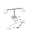
- the SSPS plan launches an artificial satellite equipped with a huge solar cell panel above the equator, and converts the electric power generated by sunlight into a microwave 100 by a transmission module in the solar cell panel. . Then, the microwave 100 is transmitted from the microwave power transmission unit 101 to the power receiving facility 102 provided on the ground, and converted into electric power again on the ground and used.
- the retrodirective function refers to receiving a pilot signal (induction signal) transmitted from the power receiving facility 102 provided on the ground by the power transmission antenna included in the microwave power transmission unit 101, and transmitting phase information of the received pilot signal to the power transmission antenna. This is a function of directing the transmission wave in the direction of arrival of the pilot signal by reflecting it in the transmission wave radiated from.
- a large-area antenna is constructed by coupling two-dimensionally arranged antenna panels of about 1 m square at coupling points. Because this large-area antenna is bent around the coupling point, the phase plane of the microwaves radiated from each antenna panel is different, and unwanted waves with high power levels may be radiated outside the target point.
- a method of aligning the phase plane has been proposed.
- Patent Document 1 discloses an example of a retrodirective function. Based on the arrival direction angle formed by the arrival direction of the pilot signal and the antenna panel, the antenna reference line orthogonal to the arrival direction of the pilot signal and each of the antenna reference lines are disclosed. The distance between the antenna elements is calculated, and the phase amount of the microwave radiated from each antenna element is determined and corrected according to each calculated distance.
- the present invention has been made in view of such circumstances, and an object thereof is to provide a phased array antenna and a phase control method thereof that can improve the accuracy of phase correction.
- the present invention employs the following means.
- the first aspect of the present invention has a configuration in which a plurality of antenna panels in which a plurality of antenna elements are arranged and arranged are connected in a straight line or a plane, and controls the phase of signals input to and output from each of the antenna elements.
- a phased array antenna that radiates a signal in the direction of arrival of a pilot signal transmitted from a reception facility, based on the pilot signal and a reference signal transmitted in common to each of the antenna panels
- a plurality of the antenna panels based on the arrival phase and the arrival direction angle formed between the arrival phase and the arrival direction of the pilot signal and the antenna panel in each of the antenna panels;
- a phased array comprising: a fixed unit; and a phase shift amount determining unit that determines a phase shift amount of a signal radiated from each antenna element based on information on the position of the antenna panel specified by the position specifying unit.
- each antenna panel receives the pilot signal and the reference signal transmitted in common to the antenna panel.
- the arrival phase of the pilot signal detected based on the pilot signal and the reference signal, and the arrival direction angle formed by the arrival direction of the pilot signal and the antenna panel are obtained.
- a predetermined reference panel is selected, and the position of each antenna panel with respect to this reference panel is estimated based on the arrival phase and the arrival direction angle.
- the amount of phase shift of the signal radiated from each antenna element is determined.
- the phased array antenna may include an instruction transmission unit that is located at a predetermined height from the surface of the reference panel and transmits the reference signal to each antenna panel.
- the distance from the reference panel is the longest compared to the case where the instruction transmission unit is located on the surface of the reference panel.
- the difference in the transmission distance of the reference signal to the antenna panel that is far away is small. Thereby, the detection error of the reference signal between the antenna panels can be reduced.
- An instruction transmitter that is located on at least one of the antenna panels of the phased array antenna and transmits the reference signal to each of the antenna panels; and the instruction transmitter A control unit that controls timing for detecting the reference signal according to the distance between the antenna panel having the instruction transmission unit and the other antenna panel with respect to the antenna panel other than the antenna panel having It is good to do. Since the instruction transmission unit is located on the antenna panel surface, the distance between the antenna panel and the other antenna panel is known, so by controlling the timing for detecting the reference signal according to the distance, the reference Signal transmission errors can be reduced.
- the position specifying unit of the phased array antenna includes a selection unit that selects the next antenna panel for specifying the position of the antenna panel, and the selection unit includes a plurality of adjacent antenna panels after the position determination.
- the antenna panels may be sequentially selected.
- the next position specifying process is performed in parallel with the selected four antenna panels. Will be done. In this way, since the positions of the antenna panels are sequentially specified in parallel based on the position information of the adjacent antenna panels, the time required for the processing for specifying the positions of the antenna panels can be shortened.
- the phased array antenna is divided into a plurality of regions, and each of the regions has the reference panel to provide a plurality of the reference panels, and a reference panel that is the most standard among the plurality of reference panels is provided.
- the reference panel other than the first reference panel and the first reference panel is a second reference panel, and the position specifying unit specifies the position of the antenna panel in each of the regions based on the reference panel in the region.
- the region having the first reference panel or the region close to the region having the first reference panel at the boundary between the adjacent regions is defined as the dominant side, and the region that is not the dominant side of the adjacent region is defined as In the case of the inferior side, the position of the antenna panel in the inferior side region is corrected based on the adjacent dominant side reference panel. It is also possible.
- the second aspect of the present invention has a configuration in which a plurality of antenna panels in which a plurality of antenna elements are arranged and arranged are connected in a straight line or a plane, and controls the phase of signals input to and output from each of the antenna elements.
- a phased array antenna that radiates a signal in the direction of arrival of a pilot signal transmitted from a reception facility, based on the pilot signal and a reference signal transmitted in common to each of the antenna panels
- a plurality of antennas based on a first process of detecting an arrival phase of the pilot signal in each antenna panel, an arrival direction angle formed by the arrival phase and the arrival direction of the pilot signal and the antenna panel; Among the panels, the position of each of the antenna panels with respect to a reference panel that is the reference antenna panel is specified.
- the phase of the phased array antenna having two processes and a third process for determining the amount of phase shift of the signal radiated from each antenna element based on the information on the position of the antenna panel specified by the second process. Provide a control
- the present invention has the effects of improving the accuracy of phase correction and speeding up phase correction.
- FIG. 1 is a block diagram showing an electrical configuration of a phased array antenna according to a first embodiment of the present invention. It is the figure which extracted and showed a part of phased array antenna shown in FIG. It is an operation
- FIG. 1 is a diagram showing a schematic configuration of a phased array antenna 1 according to the present embodiment.
- the phased array antenna 1 according to the present embodiment includes a plurality of antenna panels C that are two-dimensionally arranged in N rows and N columns on the XY plane in an O-XYZ orthogonal coordinate system. I have. Adjacent antenna panels C are coupled at each coupling point (not shown).
- Each antenna panel C is, for example, a square whose side is A (for example, about 1 m), and the large-sized phased array antenna 1 of about 2 km square as a whole is obtained by connecting the antenna panels C to each other. Has been built.
- each antenna panel C a plurality of antenna elements 20 are two-dimensionally arranged at predetermined distance intervals in the X-axis direction and the Y-axis direction.
- the antenna elements 20 are two-dimensionally arranged in the X-axis direction and the Y-axis direction so that both distance intervals are a.
- the distance between the end face of the antenna panel C and the antenna element 20 closest to the end face is a / 2.
- the instruction transmission unit 32 transmits a time synchronization pulse to each antenna panel C of the phased array antenna 1 via wireless communication.
- the height position h at which the instruction transmission unit 32 is provided is such that the phase error calculated based on the transmission distance difference of the time synchronization pulse between the reference panel P and each antenna panel C other than the reference panel P is within a predetermined range. It is preferable to set so as to be within.
- the height position h where the instruction transmission unit 32 is provided is not particularly limited, but the time between the reference panel P and each other antenna panel C increases as the distance (height) from the surface of the reference panel P increases. Since the difference in the transmission distance of the synchronization pulse is shortened, in this embodiment, the position is about 1 km from the surface of the reference panel P.
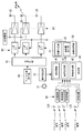
- FIG. 2 is a block diagram showing an electrical configuration of the phased array antenna 1 according to the present embodiment.
- the original vibration 31 transmits, to each antenna panel C, a reference signal fp + ⁇ p that serves as a reference when the arrival phase ⁇ between the panels is estimated by the detection unit 40 via wireless communication.
- a technique for transmitting the reference signal by the original vibration 31 is described in detail in, for example, Japanese Patent Application Laid-Open No. 2004-325162. By adopting these known techniques, it is possible to transmit the reference signal from the original vibration 31.
- the instruction transmission unit 32 outputs a pulse for synchronizing time (time synchronization pulse) to the detection unit 40.
- the predetermined frequency is a frequency at which the size of the antenna falls within a predetermined range. Even when the down-converted pilot signal f p, the relative phase of the pilot signal f p received by the receiving circuit 30 of each antenna panel is maintained.
- the detection unit 40 detects the arrival direction angle ⁇ between the antenna panel surface and the arrival direction of the pilot signal in the antenna panel C and the arrival phase ⁇ of the pilot signal in the antenna panel C for each antenna panel, and the arithmetic processing unit 50 Output to.
- the detection unit 40 includes an AD converter 41, a candidate determination unit 42, and an angle detection unit 43.
- the AD converter 41 uses the time synchronization pulse acquired from the instruction transmission unit 32 as a trigger, and uses the timing information of detection of the arrival phase ⁇ in the pilot signal f p ′ down-converted in the reception circuit 30 of each antenna panel C as a candidate determination unit. Output to 42.
- the candidate determining unit 42 the position of the reference signal at the time of receiving the timing information, to detect the arrival phase ⁇ of the pilot signal f p '.
- the position candidate R of the antenna panel C is a position candidate for an integral multiple of the wavelength.
- the candidate determination unit 42 outputs the arrival phase ⁇ and the panel position candidate R to the arithmetic processing unit 50.
- FIG. 3 shows a state in which a plurality of antenna panels C receive pilot signals from the ground.
- the candidate determining unit 42 in the antenna panel C 1j is located next to the reference panel P, on the basis of the information of the arrival phase phi 1j of the pilot signal f p, is receiving the pilot signal f p at the top of the waveform detecting the estimates by phase 360 ° of the pilot signal f p, the in which R 1j1, R 1j2, R 1j3 deviation as a candidate R of the panel position.
- Angle detecting unit 43 includes a RF interferometer by measuring the phase difference between the pilot signal f p received by a plurality of receiving antenna elements 120 each antenna panel C is provided, power receiving equipment that transmitted the pilot signal The direction of 102 (see, for example, FIG. 9) is obtained.
- the angle detection unit 43 estimates the arrival direction angle ⁇ indicating the direction of the reception facility 102 for each antenna panel C, and outputs the estimated arrival direction angle ⁇ to the arithmetic processing unit 50.
- the arithmetic processing unit 50 includes a microcomputer, and executes each phase control process described below based on the input arrival direction angle ⁇ , arrival phase ⁇ , and panel position candidate R, whereby each antenna element The amount of microwave phase shift transmitted from 20 is calculated and output to each variable phase shifter 80.
- the arithmetic processing unit 50 includes a position specifying unit 51 and a phase shift amount determining unit 52.
- the position specifying unit 51 specifies the position of each antenna panel with respect to the reference panel P among the plurality of antenna panels based on the arrival phase ⁇ and the arrival direction angle ⁇ .
- the reference panel P is fixedly set.
- the position specifying unit 51 determines the reference panel P among the panel position candidates R (for example, R 1j1 , R 1j2 , R 1j3 ...) Estimated when the arrival phase ⁇ 1j of the antenna panel C 1j is obtained.
- the panel position that is the position of the arrival direction angle ⁇ 1j from the position is selected, and the selected panel position R 1j1 is specified as the position of the antenna panel C 1j .
- the position specifying unit 51 specifies the panel position of the antenna panel C and outputs information on the panel position to the phase shift amount determining unit 52.
- the phase shift amount determining unit 52 determines the phase shift amount of the signal to be radiated from each antenna element 20 based on the information on the panel position specified by the position specifying unit 51. For example, the phase shift amount determination unit 52 acquires information on the specified panel position, and the phase shift amount of the antenna panel C adjacent to the reference panel P side from the antenna panel C that determines the phase shift amount is further determined.
- the phase shift amount of the transmission microwave transmitted from the antenna element 20 is determined based on the phase shift amount of the adjacent antenna panel C.
- the phase shift amount determining unit 52 outputs information on the phase shift amount to the variable phase shifter 80 corresponding to each antenna panel C.
- the microwave generation unit 60 generates a reference microwave signal and outputs it to the branching circuit 70.
- the demultiplexing circuit 70 demultiplexes the input reference microwave signal and outputs it to the variable phase shifter 80 provided corresponding to each antenna element 20.
- Each variable phase shifter 80 generates a phase shift amount in the reference phase microwave input from the demultiplexing circuit 70 based on the phase shift amount information input from the arithmetic processing unit 50, and the power amplifier 90. Output to.
- the power amplifier 90 is provided corresponding to each of the antenna elements 20 and amplifies the power supplied from the external power source (space solar power generation unit) to the microwave of the phase and frequency of the signal output from the variable phase shifter 80.
- the antenna element 20 radiates microwaves having respective phase differences that have been subjected to power amplification toward the power receiving facility 102 (see FIG. 9).
- FIG. 3 shows antenna panels arranged in the first row, the second row, the (k ⁇ 1) th row, and the k-th row from the reference panel P among the j-column antenna panels C 1j to C ij.
- C 1j , C 2j ... C (k ⁇ 1) j and C kj are extracted and shown as an example.
- Pilot signal f p by the respective receiving antenna elements 120 of each antenna panel C 1j to C kj is received and detected in the receiver circuit 30 (step SA1 in FIG. 4).
- the pilot signal f p is down-converted and output to the detection unit 40 by the reference signal f p + Delta] p of the master 31 is inputted (step SA2 in FIG. 4).
- the candidate determination unit 42 the arrival phase ⁇ of the down-converted pilot signal f ⁇ p for each of the antenna panels C 1j to C kj based on the time synchronization pulse input from the instruction transmission unit 32 via the AD converter 41. Is detected (step SA3 in FIG. 4), and the panel position candidate R of each of the antenna panels C 1j to C kj is estimated based on the arrival phase ⁇ (step SA4 in FIG. 4).
- step SA5 based on the pilot signal f p obtained by the antenna panel C 1j to each of the plurality of receiving antenna elements 120 of the C kj, arrival direction angle ⁇ of the antenna panel C 1j to C kj pilot signal It is estimated (step SA5 in FIG. 4). Based on the arrival phase ⁇ and the arrival direction angle ⁇ described above, the positions of the antenna panels C 1j to C kj are specified (step SA6 in FIG. 4). It is determined whether or not the panel positions of all the antenna panels C 1j to C kj have been specified (step SA7 in FIG. 4).
- the phase shift amount of the transmission microwave to be output is set for each of the antenna panels C 1j to C kj (step SA8 in FIG. 4). This process ends. If not all panel positions have been specified, the process returns to step SA6 and the process is repeated.
- the process to detect the arrival phase phi of the pilot signal f p at each antenna panel, by performing the phase control processing based on the arrival phase phi, as shown in FIG. 5, the total antenna panels C 1j to C kj The phase planes of the microwaves output from all the arranged antenna elements 20 are aligned.
- the phase setting (step SA8) based on the arrival phase ⁇ is performed when all the panel positions in step SA7 in FIG. 4 are specified. Is not limited to this.
- the phase setting (step SA8) may be performed sequentially from the antenna panel whose panel position is specified in step SA6 of FIG.
- the arrival phase of the pilot signal detected based on the pilot signal and the reference signal received at each antenna panel C. ⁇ and the arrival direction angle ⁇ formed by the arrival direction of the pilot signal and the antenna panel C are obtained.
- a predetermined reference panel P is selected, and the position of each antenna panel C with respect to this reference panel P is estimated based on the arrival phase ⁇ and the arrival direction angle ⁇ . .
- the phase shift amount of the signal radiated from each antenna element 20 is determined.
- each antenna panel C is estimated for each antenna panel C on the basis of the pilot signal detected by each antenna panel C. Therefore, the position of the plurality of connected antenna panels C is determined. No estimation error is included. Thereby, the precision of the phase correction between the antenna panels C can be improved. Also, by down-converting the pilot signal to a frequency where the antenna size is within a predetermined range, the wavelength of the pilot signal is extended, and the interval between panel position candidates estimated by the arrival phase ⁇ is widened. Thereby, the estimation precision of a panel position can be improved.
- the instruction transmission unit 32 is provided at a position having a predetermined height h on the surface of the antenna panel C, thereby reducing the time difference at which each antenna panel C receives a time synchronization pulse.
- the arrangement position of the instruction transmission unit 32 is not limited to this.
- an instruction transmission unit 32 ′ (not shown) may be provided on the surface of the antenna panel C.
- the distance between the antenna panel Cx having the instruction transmission unit 32 ′ and the other antenna panel Cy other than the antenna panel Cx having the instruction transmission unit 32 ′ is Since it becomes known, a control unit (not shown) for controlling the timing of detecting the reference signal according to the distance between the antenna panel Cx and the other antenna panel Cy is provided for the other antenna panel Cy.
- a control unit (not shown) for controlling the timing of detecting the reference signal according to the distance between the antenna panel Cx and the other antenna panel Cy is provided for the other antenna panel Cy.
- phased array antenna according to a second embodiment of the present invention is different from the first embodiment described above in that a selection unit that selects the next antenna panel for specifying the position of the antenna panel by the position estimation unit 51 is provided.
- description of points that are common to the first embodiment will be omitted, and different points will be mainly described.
- the selecting unit sequentially selects a plurality of antenna panels adjacent to the antenna panel whose panel position is specified as the antenna panel for specifying the panel position. For example, when each antenna panel is a rectangle, each antenna panel is adjacent to four antenna panels in all directions.
- the selecting unit 51 when the antenna panel for which the panel position specifying process is performed first is the first specified panel, after the position of the first specified panel is determined, the selecting unit specifies the position first. The four antenna panels adjacent to the antenna panel thus selected are selected as antenna panels that perform panel position specifying processing next.
- the antenna panel located at the approximate center of the phased array antenna is selected as the first specific panel.
- the time required for the panel position specifying process can be further shortened.
- the antenna panel located at the approximate center of the phased array antenna is set as the first specific panel, and the process of specifying 1500 panel positions vertically and horizontally is performed. Done in parallel.
- the number of processes required to specify the panel position of the antenna panel farthest from the first specific panel is about 3000 times. Thereby, the number of times of processing can be reduced as compared with the case where the first specific panel is selected as an antenna panel located at the end of the phased array antenna (for example, the number of times of processing is about 6000).
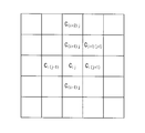
- FIG. 7 is an enlarged view of the antenna panel in the vicinity of the first specific panel.
- the selection unit specifies the four adjacent antenna panels C (i ⁇ 1) j , C after specifying the position of the center panel C ij.
- (i + 1) j , Ci (j-1) , Ci (j + 1) are selected as antenna panels for specifying the position.
- the selection unit includes two adjacent (for example, The antenna panel C (i + 2) j , C (i + 1) (j + 1) ) is then selected as the antenna panel for specifying the position. As described above, four or two antenna panels are selected by the selection unit, and the panel position specifying process is performed in parallel.
- the phase shift amount determination unit 52 determines the phase shift amount for each antenna panel based on the information on the position of each antenna panel specified by the parallel processing of the panel position as described above. In this way, a plurality of antenna panels that are adjacent to the antenna panel whose position is specified and whose position is unspecified are sequentially selected, and the panel position specifying process of the plurality of antenna panels is performed in parallel. The time required for the position specifying process can be shortened.
- the phased array antenna according to this embodiment is different from the first embodiment and the second embodiment described above in that the antenna panels are grouped into a plurality of regions and a plurality of reference panels are provided for each region.
- description of points that are common to the first embodiment and the second embodiment will be omitted, and different points will be mainly described with reference to FIG.
- the antenna panels of the phased array antenna are grouped into a plurality of areas, and each area includes a reference panel (first reference panel) or a temporary reference panel (second reference panel).
- the A area includes a reference panel (first reference panel) that is the most standard among all the antenna panels, and a temporary area other than the first reference panel is provided from the B area to the E area.
- a temporary reference panel (second reference panel) which is a reference panel is provided.
- the candidate position determination unit determines panel position candidates for each antenna panel. Specifically, in the A area, the panel position of the antenna panel is specified in order from the reference panel, and in the B area to E area, the antenna panel in each area is based on the temporary reference panel provided in each area. The panel position is temporarily specified.
- the arithmetic processing unit is inferior when the area having the reference panel or the area close to the area having the reference panel is the dominant side and the area that is not the dominant side of the adjacent area is the inferior side at the boundary between adjacent areas.
- the position of the antenna panel in this area is corrected based on the adjacent dominant reference panel.
- the arithmetic processing unit calculates a correction amount (shift amount) ⁇ of the panel position between the A region and the B region to the E region.
- the arithmetic processing unit corrects the panel position of the antenna panel in each region temporarily specified in the B region to the E region based on the correction amount ⁇ .
- the calculation processing unit specifies the panel positions of all the antenna panels, the calculation processing unit outputs it to the phase shift amount determination unit.
- the phase shift amount determination unit determines and outputs the phase shift amount based on the specified (or corrected) panel position information. As described above, since a plurality of reference panels (or temporary reference panels) serving as a reference are provided and the panel position specifying process in the grouped area is performed in parallel for each area, the panel position specifying process is performed. Time can be shortened.
Landscapes
- Engineering & Computer Science (AREA)
- Computer Networks & Wireless Communication (AREA)
- Signal Processing (AREA)
- Physics & Mathematics (AREA)
- Electromagnetism (AREA)
- Variable-Direction Aerials And Aerial Arrays (AREA)
- Radio Transmission System (AREA)
Abstract
位相補正の精度を向上させること。パイロット信号と各アンテナパネルに対して共通に送信される基準信号とに基づいて、各アンテナパネルにおけるパイロット信号の到達位相を検出する検出部(40)と、到達位相およびパイロット信号の到来方向とアンテナパネルとがなす到来方向角度に基づいて、複数のアンテナパネルのうち、基準のアンテナパネルとされる基準パネルに対する各アンテナパネルの位置を特定する位置特定部(51)と、位置特定部(51)によって特定されたアンテナパネルの位置の情報に基づいて、各アンテナ素子から放射させる信号の移相量をそれぞれ決定する移相量決定部(52)とを具備する。
Description
本発明は、例えば、SSPS(Space Solar Power System)に適用されるフェーズドアレイアンテナに関し、特に、受電設備への電力送電ビーム方向を高精度で制御することのできるフェーズドアレイアンテナ及びその位相制御方法に関するものである。
近年、化石燃料の利用による二酸化炭素排出量の増加に伴い、地球温暖化などの環境問題や化石燃料枯渇などのエネルギー問題がクローズアップされている。このため、クリーンエネルギーの需要は年々高まっており、それらの問題に対する解決方法の一つとしてSSPS計画が挙げられている。
SSPS計画とは、図9に示すように、巨大な太陽電池パネルを搭載した人口衛星を赤道上空に打ち上げ、太陽光によって発電した電力を太陽電池パネルの中の発信モジュールによりマイクロ波100に変換する。そして、マイクロ波100をマイクロ波送電部101から地上に設けた受電設備102へ送電し、地上において再び電力に変換して利用するという計画である。
SSPS計画とは、図9に示すように、巨大な太陽電池パネルを搭載した人口衛星を赤道上空に打ち上げ、太陽光によって発電した電力を太陽電池パネルの中の発信モジュールによりマイクロ波100に変換する。そして、マイクロ波100をマイクロ波送電部101から地上に設けた受電設備102へ送電し、地上において再び電力に変換して利用するという計画である。
これにより太陽発電の欠点である天候や時間帯に左右されること無く、クリーンなエネルギーを安定して供給することができる。この計画の実現のためには、大電力送電、マイクロ波ビーム制御、運用コストの低減などが技術課題として挙げられ、それらを満足させる方法の一つとして、上記マイクロ波送電部101に積層アクティブ集積アンテナ(Active Integrated Antenna:AIA)を用いる方法が挙げられている。また、送電の更なる高効率化を図るために、上記積層アクティブ集積アンテナにレトロディレクティブ機能を搭載することなどが検討されている。
上記レトロディレクティブ機能とは、地上に設けられた受電設備102から送られてくるパイロット信号(誘導信号)をマイクロ波送電部101が備える送電アンテナにより受信し、受信したパイロット信号の位相情報を送電アンテナから放射させる送信波に反映させることによって、この送信波をパイロット信号の到来方向に指向させる機能である。
上記レトロディレクティブ機能とは、地上に設けられた受電設備102から送られてくるパイロット信号(誘導信号)をマイクロ波送電部101が備える送電アンテナにより受信し、受信したパイロット信号の位相情報を送電アンテナから放射させる送信波に反映させることによって、この送信波をパイロット信号の到来方向に指向させる機能である。
SSPSにおける送電アンテナでは、二次元配列された約1m四方のアンテナパネルがそれぞれ結合点にて結合されることにより、大面積のアンテナを構築している。この大面積のアンテナは、結合点を中心に折れ曲がったりすることにより、各アンテナパネルから放射させるマイクロ波の位相面が異なり、電力レベルの高い不要波が目標地点以外に放射されることもあるため、位相面を揃える方法が提案されている。
例えば、特許文献1には、レトロディレクティブ機能の一例が開示されており、パイロット信号の到来方向とアンテナパネルとがなす到来方向角度に基づいて、パイロット信号の到来方向に直交するアンテナ基準線と各アンテナ素子との間の距離を算出し、算出されたそれぞれの距離に応じて、各アンテナ素子から放射させるマイクロ波の位相量を決定し、補正している。
例えば、特許文献1には、レトロディレクティブ機能の一例が開示されており、パイロット信号の到来方向とアンテナパネルとがなす到来方向角度に基づいて、パイロット信号の到来方向に直交するアンテナ基準線と各アンテナ素子との間の距離を算出し、算出されたそれぞれの距離に応じて、各アンテナ素子から放射させるマイクロ波の位相量を決定し、補正している。
しかしながら、上記特許文献1の方法では、基準とするパネルを起点として、順に隣のパネルの移相量を決定し、補正していたため、接続された従前のアンテナパネルの位置の推定誤差が含まれている場合には、その推定誤差を含んだ状態で、順次位相差を計算していくこととなり、基準とするパネルから離れるに従って位相補正の精度が低下するという問題があった。
本発明は、このような事情に鑑みてなされたものであって、位相補正の精度を向上させることのできるフェーズドアレイアンテナ及びその位相制御方法を提供することを目的とする。
上記課題を解決するために、本発明は以下の手段を採用する。
本発明の第1の態様は、複数のアンテナ素子が配列配置された複数のアンテナパネルを直線状又は平面状に接続した構成を有し、各前記アンテナ素子に入出力する信号の位相を制御することにより、受信設備から送信されたパイロット信号の到来方向に対し信号を放射するフェーズドアレイアンテナであって、前記パイロット信号と、各前記アンテナパネルに対して共通に送信される基準信号とに基づいて、各前記アンテナパネルにおける、前記パイロット信号の到達位相を検出する検出部と、前記到達位相、および前記パイロット信号の到来方向と前記アンテナパネルとがなす到来方向角度に基づいて、複数の前記アンテナパネルのうち、基準の前記アンテナパネルとされる基準パネルに対する各前記アンテナパネルの位置を特定する位置特定部と、前記位置特定部によって特定された前記アンテナパネルの位置の情報に基づいて、各前記アンテナ素子から放射させる信号の移相量をそれぞれ決定する移相量決定部とを具備するフェーズドアレイアンテナを提供する。
本発明の第1の態様は、複数のアンテナ素子が配列配置された複数のアンテナパネルを直線状又は平面状に接続した構成を有し、各前記アンテナ素子に入出力する信号の位相を制御することにより、受信設備から送信されたパイロット信号の到来方向に対し信号を放射するフェーズドアレイアンテナであって、前記パイロット信号と、各前記アンテナパネルに対して共通に送信される基準信号とに基づいて、各前記アンテナパネルにおける、前記パイロット信号の到達位相を検出する検出部と、前記到達位相、および前記パイロット信号の到来方向と前記アンテナパネルとがなす到来方向角度に基づいて、複数の前記アンテナパネルのうち、基準の前記アンテナパネルとされる基準パネルに対する各前記アンテナパネルの位置を特定する位置特定部と、前記位置特定部によって特定された前記アンテナパネルの位置の情報に基づいて、各前記アンテナ素子から放射させる信号の移相量をそれぞれ決定する移相量決定部とを具備するフェーズドアレイアンテナを提供する。
上記構成によれば、各アンテナパネルにおいて、パイロット信号とアンテナパネルに対して共通に送信される基準信号とが受信される。これらパイロット信号と基準信号とに基づいて検出されるパイロット信号の到達位相、およびパイロット信号の到来方向とアンテナパネルとがなす到来方向角度が得られる。そして、各アンテナパネルの位置を得るために、所定の基準パネルを選定し、到達位相および到来方向角度に基づいて、この基準パネルに対する各アンテナパネルの位置がそれぞれ推定される。こうして推定された基準パネルに対するアンテナパネルの位置の情報に基づいて、各アンテナ素子から放射させる信号の移相量が決定される。
このように、各アンテナパネルの位置は、それぞれのアンテナパネルにおいて検出されたパイロット信号が基準として推定されるので、接続された従前の複数のアンテナパネルの位置の推定誤差が含まれることはない。これにより、アンテナパネル間の位相補正の精度を向上させることができる。
このように、各アンテナパネルの位置は、それぞれのアンテナパネルにおいて検出されたパイロット信号が基準として推定されるので、接続された従前の複数のアンテナパネルの位置の推定誤差が含まれることはない。これにより、アンテナパネル間の位相補正の精度を向上させることができる。
上記フェーズドアレイアンテナの前記基準パネルの面上から所定高さに位置し、各前記アンテナパネルに対して前記基準信号を送信する指示送信部を具備することとしてもよい。
基準パネルの面上から所定高さに位置する指示送信部から基準信号が送信されることにより、基準パネルの面上に指示送信部が位置している場合と比較して、基準パネルから最も距離の離れているアンテナパネルまでの基準信号の伝達距離差が小さくなる。これにより、各アンテナパネル間における基準信号の検出誤差を低減することができる。
基準パネルの面上から所定高さに位置する指示送信部から基準信号が送信されることにより、基準パネルの面上に指示送信部が位置している場合と比較して、基準パネルから最も距離の離れているアンテナパネルまでの基準信号の伝達距離差が小さくなる。これにより、各アンテナパネル間における基準信号の検出誤差を低減することができる。
上記フェーズドアレイアンテナの複数の前記アンテナパネルのうち、少なくともいずれか1つの前記アンテナパネル面上に位置し、各前記アンテナパネルに対して前記基準信号を送信する指示送信部と、前記指示送信部を有する前記アンテナパネル以外の他の前記アンテナパネルに対し、前記指示送信部を有する前記アンテナパネルと他の前記アンテナパネルとの距離に応じた前記基準信号を検出させるタイミングを制御する制御部とを具備することとしてもよい。
アンテナパネル面上に指示送信部が位置していることから、アンテナパネルと他のアンテナパネルとの距離が既知となるので、その距離に応じて基準信号を検出させるタイミングを制御することにより、基準信号の伝達誤差を低減させることができる。
アンテナパネル面上に指示送信部が位置していることから、アンテナパネルと他のアンテナパネルとの距離が既知となるので、その距離に応じて基準信号を検出させるタイミングを制御することにより、基準信号の伝達誤差を低減させることができる。
上記フェーズドアレイアンテナの前記位置特定部において、前記アンテナパネルの位置を特定する次の前記アンテナパネルを選定する選定部を具備し、前記選定部は、位置決定後の前記アンテナパネルに隣接する複数の前記アンテナパネルを順次選定することとしてもよい。
例えば四角形のアンテナパネルである場合には、四方に4つのアンテナパネルが隣接している。位置特定部が位置を特定したアンテナパネルに隣接する4つのアンテナパネルを、次に位置特定処理を行うアンテナパネルとして選定すれば、次の位置特定処理は選定された4つのアンテナパネルで並行して行われることになる。このようにして、隣り合うアンテナパネルの位置情報に基づいて、アンテナパネルの位置が並行して順次特定されるので、アンテナパネルの位置特定にかかる処理にかかる時間が短縮できる。
上記フェーズドアレイアンテナは、複数の領域に分けられ、各前記領域にそれぞれ前記基準パネルを有することにより複数の前記基準パネルを設けるとともに、複数の該基準パネル間のうちで最も基準となる基準パネルを第1基準パネル、該第1基準パネル以外の前記基準パネルを第2基準パネルとし、前記位置特定部は、各前記領域において、該領域内の前記基準パネルに基づいて前記アンテナパネルの位置を特定し、隣接する前記領域の境界において、前記第1基準パネルを有する前記領域、または前記第1基準パネルを有する前記領域に近い前記領域を優勢側とし、隣接する前記領域の優勢側でない前記領域を劣勢側とした場合に、劣勢側の前記領域の前記アンテナパネルの位置を、隣接する優勢側の前記基準パネルに基づいて補正することとしてもよい。
このように、分けられた領域毎に基準パネルを有することにより、フェーズドアレイアンテナには複数の基準パネルが設けられる。また、領域毎に基準パネルに基づいてアンテナパネルの位置が特定されるので、並行処理が可能となり、処理にかかる時間を短縮することができる。
このように、分けられた領域毎に基準パネルを有することにより、フェーズドアレイアンテナには複数の基準パネルが設けられる。また、領域毎に基準パネルに基づいてアンテナパネルの位置が特定されるので、並行処理が可能となり、処理にかかる時間を短縮することができる。
本発明の第2の態様は、複数のアンテナ素子が配列配置された複数のアンテナパネルを直線状又は平面状に接続した構成を有し、各前記アンテナ素子に入出力する信号の位相を制御することにより、受信設備から送信されたパイロット信号の到来方向に対し信号を放射するフェーズドアレイアンテナであって、前記パイロット信号と、各前記アンテナパネルに対して共通に送信される基準信号とに基づいて、各前記アンテナパネルにおける、前記パイロット信号の到達位相を検出する第1過程と、前記到達位相、および前記パイロット信号の到来方向と前記アンテナパネルとがなす到来方向角度に基づいて、複数の前記アンテナパネルのうち、基準の前記アンテナパネルとされる基準パネルに対する各前記アンテナパネルの位置を特定する第2過程と、前記第2過程によって特定された前記アンテナパネルの位置の情報に基づいて、各前記アンテナ素子から放射させる信号の移相量をそれぞれ決定する第3過程とを有するフェーズドアレイアンテナの位相制御方法を提供する。
本発明は、位相補正の精度を向上させ、かつ、位相補正を高速化することができるという効果を奏する。
以下に、本発明に係るフェーズドアレイアンテナ及びその位相制御方法の実施形態について、図面を参照して説明する。
〔第1の実施形態〕
以下に、本発明に係るフェーズドアレイアンテナをSSPSに適用した場合を例に挙げて説明する。
図1は、本実施形態に係るフェーズドアレイアンテナ1の概略構成を示した図である。図1に示されるように、本実施形態に係るフェーズドアレイアンテナ1は、O-XYZの直交座標系において、X-Y平面上にN行N列で二次元配列された複数のアンテナパネルCを備えている。隣接するアンテナパネルCは、各結合点(図示略)において、結合されている。各アンテナパネルCは、例えば、一辺がA(例えば、1m程度)の正方形であり、このようなアンテナパネルCが互いに結合されていることにより、パネル全体として約2km四方の大型フェーズドアレイアンテナ1が構築されている。
〔第1の実施形態〕
以下に、本発明に係るフェーズドアレイアンテナをSSPSに適用した場合を例に挙げて説明する。
図1は、本実施形態に係るフェーズドアレイアンテナ1の概略構成を示した図である。図1に示されるように、本実施形態に係るフェーズドアレイアンテナ1は、O-XYZの直交座標系において、X-Y平面上にN行N列で二次元配列された複数のアンテナパネルCを備えている。隣接するアンテナパネルCは、各結合点(図示略)において、結合されている。各アンテナパネルCは、例えば、一辺がA(例えば、1m程度)の正方形であり、このようなアンテナパネルCが互いに結合されていることにより、パネル全体として約2km四方の大型フェーズドアレイアンテナ1が構築されている。
各アンテナパネルCには、複数のアンテナ素子20がX軸方向及びY軸方向に所定の距離間隔で、二次元配列されている。例えば、各アンテナパネルCには、X軸方向及びY軸方向に、互いの距離間隔がいずれもaとなるように、アンテナ素子20が2次元配列されている。アンテナパネルCの端面とその端面に最も近いアンテナ素子20との距離は、いずれもa/2とされている。
図1に示されるように、フェーズドアレイアンテナ1が有する複数のアンテナパネルCのうち、基準となるアンテナパネルCを基準パネルPとした場合に、基準パネルPの面上から所定高さhの位置に指示送信部32を備えている。指示送信部32は、無線通信を介して、フェーズドアレイアンテナ1の各アンテナパネルCに対して時刻同期パルスを送信する。
指示送信部32の設けられる高さ位置hは、基準パネルPと基準パネルP以外の他の各アンテナパネルCとの時刻同期パルスの伝達距離差に基づいて算出される位相の誤差が、所定範囲内におさまるように設定することが好ましい。指示送信部32が設けられる高さ位置hは、特に限定されないが、基準パネルPの面上からの距離(高さ)が大きくなるほど、基準パネルPと他の各アンテナパネルCとの間の時刻同期パルスの伝達距離差が短くなることから、本実施形態においては、基準パネルPの面上から約1キロメートルの位置とする。
次に、本実施形態に係るフェーズドアレイアンテナ1の電気的構成について、図2を参照して説明する。図2は、本実施形態に係るフェーズドアレイアンテナ1の電気的構成を示すブロック図である。この図において、図1と同一の構成要素には、同一の符号を付している。
原振31は、無線通信を介し、検出部40によって各パネル間の到達位相φを推定する場合の基準となる基準信号fp+Δpを、各アンテナパネルCに対して送信する。原振31によって、基準信号を送信する手法については、例えば、特開2004-325162号公報に詳述されている。これらの周知技術を採用することにより、原振31から基準信号を送信することが可能である。
指示送信部32は、時刻を同期させるパルス(時刻同期パルス)を検出部40に出力する。
原振31は、無線通信を介し、検出部40によって各パネル間の到達位相φを推定する場合の基準となる基準信号fp+Δpを、各アンテナパネルCに対して送信する。原振31によって、基準信号を送信する手法については、例えば、特開2004-325162号公報に詳述されている。これらの周知技術を採用することにより、原振31から基準信号を送信することが可能である。
指示送信部32は、時刻を同期させるパルス(時刻同期パルス)を検出部40に出力する。
受信回路30は、アンテナパネルC毎に設けられ、各アンテナパネルCの受信用アンテナ素子120により受信されたパイロット信号fpを所定の周波数とするべく基準信号fp+Δpに基づいてダウンコンバートし、ダウンコンバートされたパイロット信号fp´(=fΔp=fp+Δp-fp)を検出部40に出力する。ここで、所定の周波数は、アンテナの大きさが所定範囲内となる周波数である。パイロット信号fpをダウンコンバートした場合であっても、各アンテナパネルの受信回路30で受信したパイロット信号fpの相対的な位相は維持されている。
検出部40は、アンテナパネルCにおける、アンテナパネル面とパイロット信号の到来方向とがなす到来方向角度θ、およびアンテナパネルCにおけるパイロット信号の到達位相φをアンテナパネル毎に検出し、演算処理部50に出力する。具体的には、検出部40は、AD変換器41、候補決定部42および角度検出部43を備えている。
AD変換器41は、指示送信部32から取得した時刻同期パルスをトリガとし、各アンテナパネルCの受信回路30においてダウンコンバートされたパイロット信号fp´における到達位相φ検出のタイミング情報を候補決定部42に出力する。
AD変換器41は、指示送信部32から取得した時刻同期パルスをトリガとし、各アンテナパネルCの受信回路30においてダウンコンバートされたパイロット信号fp´における到達位相φ検出のタイミング情報を候補決定部42に出力する。
候補決定部42は、基準信号fp+Δpに基づいてダウンコンバートされたパイロット信号fp´と、AD変換器41から取得したタイミング情報とに基づいて、アンテナパネルC毎にパイロット信号fp´の到達位相φを検出する。つまり、候補決定部42は、タイミング情報を受信した時点における基準信号の位置により、パイロット信号fp´の到達位相φを検出する。候補決定部42は、アンテナパネルC毎に、パイロット信号fpの到達位相φに基づいてアンテナパネルCの位置(以下「パネル位置」という)の候補Rを推定する。アンテナパネルCの位置の候補Rは、波長の整数倍分の位置候補である。候補決定部42は、到達位相φとパネル位置の候補Rとを演算処理部50に出力する。
図3には、複数のアンテナパネルCが、地上からのパイロット信号を受信する様子を示している。例えば、候補決定部42は、基準パネルPの隣に位置するアンテナパネルC1jにおいて、パイロット信号fpの到達位相φ1jの情報に基づいて、パイロット信号fpを波形の頂上で受信していると検出し、パイロット信号fpの位相が360°ずつ、ずれているR1j1,R1j2,R1j3をパネル位置の候補Rとして推定する。
角度検出部43は、RF干渉計を備えており、各アンテナパネルCが備える複数の受信用アンテナ素子120により受信されたパイロット信号fpの位相差を測ることにより、パイロット信号を送信した受電設備102(例えば、図9参照)の方向を求める。角度検出部43は、アンテナパネルC毎に、上記受信設備102の方向を示す到来方向角度θを推定し、演算処理部50へ出力する。
演算処理部50は、マイクロコンピュータを備えており、入力された到来方向角度θ、到達位相φ、およびパネル位置の候補Rとに基づいて、後述の位相制御処理を実行することにより、各アンテナ素子20から送出させるマイクロ波の移相量を演算し、各可変移相器80へ出力する。具体的には、演算処理部50は、位置特定部51および移相量決定部52を備えている。
位置特定部51は、到達位相φおよび到来方向角度θに基づいて、複数のアンテナパネルのうち、基準パネルPに対する各アンテナパネルの位置を特定する。また、基準パネルPは固定的に設定されている。
位置特定部51は、到達位相φおよび到来方向角度θに基づいて、複数のアンテナパネルのうち、基準パネルPに対する各アンテナパネルの位置を特定する。また、基準パネルPは固定的に設定されている。
ここで、図3を用いて、基準パネルPの1つ隣のアンテナパネルC1jの位置を推定する場合を例に挙げて説明する。位置特定部51は、アンテナパネルC1jの到達位相φ1jを求めた際に推定されたパネル位置の候補R(例えば、R1j1,R1j2,R1j3・・・)のうち、基準パネルPの位置から到来方向角度θ1jの位置となるパネル位置を選定し、選定されたパネル位置R1j1をアンテナパネルC1jの位置と特定する。
このように、位置特定部51は、アンテナパネルCのパネル位置を特定するとともに、パネル位置の情報を移相量決定部52に出力する。ここでは、アンテナパネルの到来方向角度θの誤差が、波長よりも小さいこととする。
移相量決定部52は、位置特定部51によって特定されたパネル位置の情報に基づいて、各アンテナ素子20から放射させる信号の移相量をそれぞれ決定する。例えば、移相量決定部52は、特定されたパネル位置の情報を取得しており、さらに、移相量を決定するアンテナパネルCより基準パネルP側に隣接するアンテナパネルCの移相量が決定している場合には、その隣接するアンテナパネルCの移相量に基づいて、アンテナ素子20から送出させる送電マイクロ波の移相量を決定する。移相量決定部52は、送電マイクロ波の移相量を決定すると、各アンテナパネルCに対応する可変移相器80に移相量の情報を出力する。
移相量決定部52は、位置特定部51によって特定されたパネル位置の情報に基づいて、各アンテナ素子20から放射させる信号の移相量をそれぞれ決定する。例えば、移相量決定部52は、特定されたパネル位置の情報を取得しており、さらに、移相量を決定するアンテナパネルCより基準パネルP側に隣接するアンテナパネルCの移相量が決定している場合には、その隣接するアンテナパネルCの移相量に基づいて、アンテナ素子20から送出させる送電マイクロ波の移相量を決定する。移相量決定部52は、送電マイクロ波の移相量を決定すると、各アンテナパネルCに対応する可変移相器80に移相量の情報を出力する。
一方、マイクロ波発生部60は、基準マイクロ波信号を生成して分波回路70へ出力する。分波回路70は、入力された基準マイクロ波信号を分波して、各アンテナ素子20にそれぞれ対応して設けられている可変移相器80に出力する。
各可変移相器80は、演算処理部50からそれぞれ入力された移相量の情報に基づいて、分波回路70から入力された基準位相のマイクロ波に移相量を生じさせ、電力増幅器90に出力する。
電力増幅器90は、アンテナ素子20にそれぞれ対応して設けられ、外部電源(宇宙太陽発電部)より供給された電力を可変移相器80から出力される信号の位相及び周波数のマイクロ波へ増幅し、アンテナ素子20へ出力する。
アンテナ素子20は、それぞれ電力増幅された各位相差を有するマイクロ波を受電設備102(図9参照)に向けて放射する。
各可変移相器80は、演算処理部50からそれぞれ入力された移相量の情報に基づいて、分波回路70から入力された基準位相のマイクロ波に移相量を生じさせ、電力増幅器90に出力する。
電力増幅器90は、アンテナ素子20にそれぞれ対応して設けられ、外部電源(宇宙太陽発電部)より供給された電力を可変移相器80から出力される信号の位相及び周波数のマイクロ波へ増幅し、アンテナ素子20へ出力する。
アンテナ素子20は、それぞれ電力増幅された各位相差を有するマイクロ波を受電設備102(図9参照)に向けて放射する。
次に、上述した演算処理部50により行われる位相制御処理について、図4を用いて説明する。以下の説明においては、iおよびjはパネルの位置を示す番号であり、iを行番号(i=1からk)、jを列番号(j=1からn)とし、j列のうち、基準パネルPの隣に位置しているアンテナパネルをアンテナパネルC1j、最も上端に位置しているアンテナパネルをアンテナパネルCijと定義する。図3には、j列のアンテナパネルC1j乃至Cijのうち、基準パネルPから数えて1行目、2行目、(k-1)行目、k行目に配置されているアンテナパネルC1j、C2j・・・C(k-1)j、Ckjが一例として抜き出されて示されている。
各アンテナパネルC1j乃至Ckjのそれぞれの受信用アンテナ素子120によってパイロット信号fpが受信され、受信回路30に検出される(図4のステップSA1)。受信回路30において、入力される原振31の基準信号fp+Δpによってパイロット信号fpがダウンコンバートされ、検出部40に出力される(図4のステップSA2)。候補決定部42において、AD変換器41を介して指示送信部32から入力された時刻同期パルスに基づいて、アンテナパネルC1j乃至Ckj毎に、ダウンコンバートされたパイロット信号fΔpの到達位相φが検出され(図4のステップSA3)、この到達位相φに基づいて各アンテナパネルC1j乃至Ckjのパネル位置の候補Rが推定される(図4のステップSA4)。
角度検出部43において、アンテナパネルC1j乃至Ckjのそれぞれの複数の受信用アンテナ素子120によって取得したパイロット信号fpに基づいて、アンテナパネルC1j乃至Ckjのパイロット信号の到来方向角度θが推定される(図4のステップSA5)。上述した到達位相φと到来方向角度θとに基づいて、各アンテナパネルC1j乃至Ckjの位置が特定される(図4のステップSA6)。全てのアンテナパネルC1j乃至Ckjのパネル位置が特定されたか否かが判定される(図4のステップSA7)。
全てのアンテナパネルに対してパネル位置が特定されている場合には、各アンテナパネルC1j乃至Ckjに対し、それぞれ出力させる送電マイクロ波の移相量が設定され(図4のステップSA8)、本処理を終了する。全てのパネル位置が特定されていない場合には、ステップSA6に戻り、処理を繰り返す。
このように、各アンテナパネルにおいてパイロット信号fpの到達位相φを検出し、到達位相φに基づいた位相制御処理を行うことにより、図5に示すように、全アンテナパネルC1j乃至Ckjに配置された全アンテナ素子20から出力されるマイクロ波の位相面が揃えられる。
このように、各アンテナパネルにおいてパイロット信号fpの到達位相φを検出し、到達位相φに基づいた位相制御処理を行うことにより、図5に示すように、全アンテナパネルC1j乃至Ckjに配置された全アンテナ素子20から出力されるマイクロ波の位相面が揃えられる。
本実施形態における位相制御処理においては、図4のステップSA7の全てのパネル位置が特定された段階で、到達位相φに基づいた位相設定(ステップSA8)を行うこととしていたが、位相制御のタイミングはこれに限定されない。例えば、図4のステップSA6においてパネル位置が特定されたアンテナパネルから順次、位相設定(ステップSA8)を行うこととしてもよい。
以上説明してきたように、本実施形態に係るフェーズドアレイアンテナ1及びその位相制御方法によれば、各アンテナパネルCにおいて受信されたパイロット信号と基準信号とに基づいて検出されるパイロット信号の到達位相φ、およびパイロット信号の到来方向とアンテナパネルCとがなす到来方向角度θが得られる。そして、各アンテナパネルCの位置を得るために、所定の基準パネルPを選定し、到達位相φおよび到来方向角度θに基づいて、この基準パネルPに対する各アンテナパネルCの位置がそれぞれ推定される。こうして推定された基準パネルPに対するアンテナパネルCの位置の情報に基づいて、各アンテナ素子20から放射させる信号の移相量が決定される。
このように、各アンテナパネルCの位置は、それぞれのアンテナパネルCが検出したパイロット信号を基準として、アンテナパネルC毎にそれぞれ推定されるので、接続された従前の複数のアンテナパネルCの位置の推定誤差が含まれることはない。これにより、アンテナパネルC間の位相補正の精度を向上させることができる。また、パイロット信号を、アンテナの大きさが所定範囲内となる周波数にダウンコンバートすることにより、パイロット信号の波長が延び、到達位相φによって推定されるパネル位置の候補の間隔が広くなる。これにより、パネル位置の推定精度を向上させることができる。
基準パネルPの面上から所定高さhに位置する指示送信部32から基準信号が送信されることにより、基準パネルPの面上に指示送信部32が位置している場合と比較して、基準パネルPから最も距離の離れているアンテナパネルCまでの基準信号の伝達距離差が小さくなる。これにより、各アンテナパネル間における基準信号の検出誤差を低減することができるので、より精度よく位相補正を行うことができる。
本実施形態においては、指示送信部32は、アンテナパネルCの面上の所定高さhの位置に設けることにより、各アンテナパネルCが時刻同期パルスを受信する時間差を低減することとしていたが、指示送信部32の配置位置はこれに限定されない。例えば、アンテナパネルCの面上に、指示送信部32´(図示略)を設けることとしてもよい。アンテナパネルCの面上に指示送信部32´を設ける場合には、指示送信部32´を有するアンテナパネルCxと指示送信部32´を有するアンテナパネルCx以外の他のアンテナパネルCyとの距離が既知となるので、他のアンテナパネルCyに対し、アンテナパネルCxと他のアンテナパネルCyとの距離に応じて基準信号を検出させるタイミングを制御する制御部(図示略)を設ける。このように、指示送信部32´を有するアンテナパネルCxと他のアンテナパネルCyとの距離に応じて基準信号を検出させるタイミングを制御することにより、基準信号の伝達誤差を低減させることができ、位相補正の精度を向上させることができる。
〔第2の実施形態〕
次に、本発明の第2の実施形態に係るフェーズドアレイアンテナについて説明する。
本実施形態に係るフェーズドアレイアンテナは、さらに、位置推定部51によってアンテナパネルの位置を特定する次のアンテナパネルを選定する選定部を設ける点で、上述の第1の実施形態と異なる。以下、本実施形態に係るフェーズドアレイアンテナについて、第1の実施形態と共通する点については説明を省略し、異なる点について主に説明する。
次に、本発明の第2の実施形態に係るフェーズドアレイアンテナについて説明する。
本実施形態に係るフェーズドアレイアンテナは、さらに、位置推定部51によってアンテナパネルの位置を特定する次のアンテナパネルを選定する選定部を設ける点で、上述の第1の実施形態と異なる。以下、本実施形態に係るフェーズドアレイアンテナについて、第1の実施形態と共通する点については説明を省略し、異なる点について主に説明する。
選定部(図示略)は、パネル位置が特定されたアンテナパネルに隣接する複数のアンテナパネルを、次にパネル位置を特定するアンテナパネルとして順次選定する。例えば、各アンテナパネルが四角形である場合には、各アンテナパネルは四方に4つのアンテナパネルが隣接する。ここで、位置特定部51において、最初にパネル位置の特定処理されるアンテナパネルを第1特定パネルとした場合に、第1特定パネルの位置を決定した後、選定部は、先に位置を特定したアンテナパネルに隣接する4つのアンテナパネルを、次にパネル位置の特定処理を行うアンテナパネルとして選定する。
より好ましくは、図6に示されるように、フェーズドアレイアンテナの略中心に位置するアンテナパネルを第1特定パネルに選定する。これにより、パネル位置の特定処理にかかる時間をより短縮させることができる。例えば、縦横にそれぞれ3000枚のアンテナパネルが配置されている場合に、フェーズドアレイアンテナの略中心に位置するアンテナパネルを第1特定パネルとし、四方に向けて縦横1500枚のパネル位置の特定処理が並行して行われる。このとき、第1特定パネルから最も距離の離れたアンテナパネルのパネル位置を特定するまでに必要となる処理回数は、約3000回となる。これにより、第1特定パネルをフェーズドアレイアンテナの端部に位置するアンテナパネルとして選定した場合(例えば、処理回数は約6000回)よりも、処理回数を低減することができる。
図7は、第1特定パネル近傍のアンテナパネルを抜き出して拡大した図である。
例えば、フェーズドアレイアンテナにおいて、中心パネルCijを第1特定パネルとする場合に、中心パネルCijの位置を特定した後、選定部は隣接する4つのアンテナパネルC(i-1)j,C(i+1)j,Ci(j-1),Ci(j+1)を次に位置を特定するアンテナパネルとして選定する。さらに、上記選定されたアンテナパネル(例えば、上記4つのアンテナパネルのうちの1つであるアンテナパネルC(i+1)j)のパネル位置が特定された後、選定部は隣接する2つ(例えば、アンテナパネルC(i+2)j,C(i+1)(j+1))を次に位置を特定するアンテナパネルとして選定する。このように、選定部により、アンテナパネルが4つまたは2つずつ選定され、パネル位置の特定処理が並行して行われる。
例えば、フェーズドアレイアンテナにおいて、中心パネルCijを第1特定パネルとする場合に、中心パネルCijの位置を特定した後、選定部は隣接する4つのアンテナパネルC(i-1)j,C(i+1)j,Ci(j-1),Ci(j+1)を次に位置を特定するアンテナパネルとして選定する。さらに、上記選定されたアンテナパネル(例えば、上記4つのアンテナパネルのうちの1つであるアンテナパネルC(i+1)j)のパネル位置が特定された後、選定部は隣接する2つ(例えば、アンテナパネルC(i+2)j,C(i+1)(j+1))を次に位置を特定するアンテナパネルとして選定する。このように、選定部により、アンテナパネルが4つまたは2つずつ選定され、パネル位置の特定処理が並行して行われる。
移相量決定部52は、上述したようにパネル位置の並行処理によって特定された各アンテナパネルの位置の情報に基づいて、各アンテナパネルに対する移相量を決定する。
このように、位置が特定されたアンテナパネルに隣接し、位置が未特定になっている複数のアンテナパネルが順次選定され、複数のアンテナパネルのパネル位置の特定処理が並行に行われるので、パネル位置の特定処理にかかる時間を短縮できる。
このように、位置が特定されたアンテナパネルに隣接し、位置が未特定になっている複数のアンテナパネルが順次選定され、複数のアンテナパネルのパネル位置の特定処理が並行に行われるので、パネル位置の特定処理にかかる時間を短縮できる。
〔第3の実施形態〕
本実施形態に係るフェーズドアレイアンテナは、アンテナパネルを複数の領域にグループ分けし、各領域毎に基準パネルを複数設ける点で、上述の第1の実施形態、第2の実施形態と異なる。以下、本実施形態に係るフェーズドアレイアンテナについて、第1の実施形態、第2の実施形態と共通する点については説明を省略し、図8を用いて、異なる点について主に説明する。
本実施形態に係るフェーズドアレイアンテナは、アンテナパネルを複数の領域にグループ分けし、各領域毎に基準パネルを複数設ける点で、上述の第1の実施形態、第2の実施形態と異なる。以下、本実施形態に係るフェーズドアレイアンテナについて、第1の実施形態、第2の実施形態と共通する点については説明を省略し、図8を用いて、異なる点について主に説明する。
本実施形態においては、フェーズドアレイアンテナを複数の領域に分割(グループ分け)した領域のうちの一部である、A領域からE領域の5つのグループを例に挙げて説明する。図8には、フェーズドアレイアンテナのアンテナパネルが、複数の領域にグループ分けされ、各領域に基準パネル(第1基準パネル)または仮基準パネル(第2基準パネル)を備える。本実施形態においては、A領域には、全てのアンテナパネルのうちで、最も基準となる基準パネル(第1基準パネル)を備え、B領域からE領域には、第1基準パネル以外の仮の基準パネルである仮基準パネル(第2基準パネル)を備える。
A領域からE領域のそれぞれの領域においては、第1の実施形態で述べた通り、候補決定部によって各アンテナパネルのパネル位置の候補が決定される。具体的には、A領域においては、基準パネルから順にアンテナパネルのパネル位置が特定され、B領域からE領域においては、それぞれの領域に設けられた仮基準パネルを基準として各領域内のアンテナパネルのパネル位置が仮に特定される。
演算処理部は、隣接する領域の境界において、基準パネルを有する領域、または基準パネルを有する領域に近い領域を優勢側とし、隣接する領域の優勢側でない領域を劣勢側とした場合に、劣勢側の領域のアンテナパネルの位置を、隣接する優勢側の基準パネルに基づいて補正する。例えば、演算処理部は、A領域と、B領域からE領域とのパネル位置の補正量(ずれ量)Δを算出する。演算処理部は、補正量Δを算出すると、B領域からE領域において仮に特定されたそれぞれの領域のアンテナパネルのパネル位置を、補正量Δに基づいて補正する。このようにして、B領域からE領域におけるアンテナパネルのパネル位置の情報は、A領域のパネル位置を基準として特定される。演算処理部は全アンテナパネルのパネル位置を特定すると移相量決定部に出力する。
移相量決定部は、特定(または補正)されたパネル位置の情報に基づいて、移相量を決定し、出力する。このように、基準となる基準パネル(または、仮基準パネル)を複数設け、グループ分けされた領域内でのパネル位置の特定処理を領域毎に並行して行うので、パネル位置の特定処理にかかる時間を短縮することができる。
1 フェーズドアレイアンテナ
31 原振
32 指示送信部
40 検出部
42 候補決定部
50 演算処理部
51 位置特定部
52 移相量決定部
31 原振
32 指示送信部
40 検出部
42 候補決定部
50 演算処理部
51 位置特定部
52 移相量決定部
Claims (6)
- 複数のアンテナ素子が配列配置された複数のアンテナパネルを直線状又は平面状に接続した構成を有し、各前記アンテナ素子に入出力する信号の位相を制御することにより、受信設備から送信されたパイロット信号の到来方向に対し信号を放射するフェーズドアレイアンテナであって、
前記パイロット信号と、各前記アンテナパネルに対して共通に送信される基準信号とに基づいて、各前記アンテナパネルにおける、前記パイロット信号の到達位相を検出する検出部と、
前記到達位相、および前記パイロット信号の到来方向と前記アンテナパネルとがなす到来方向角度に基づいて、複数の前記アンテナパネルのうち、基準の前記アンテナパネルとされる基準パネルに対する各前記アンテナパネルの位置を特定する位置特定部と、
前記位置特定部によって特定された前記アンテナパネルの位置の情報に基づいて、各前記アンテナ素子から放射させる信号の移相量をそれぞれ決定する移相量決定部と
を具備するフェーズドアレイアンテナ。 - 前記基準パネルの面上から所定高さに位置し、各前記アンテナパネルに対して前記基準信号を送信する指示送信部を具備する請求項1に記載のフェーズドアレイアンテナ。
- 複数の前記アンテナパネルのうち、少なくともいずれか1つの前記アンテナパネル面上に位置し、各前記アンテナパネルに対して前記基準信号を送信する指示送信部と、
前記指示送信部を有する前記アンテナパネル以外の他の前記アンテナパネルに対し、前記指示送信部を有する前記アンテナパネルと他の前記アンテナパネルとの距離に応じた前記基準信号を検出させるタイミングを制御する制御部と
を具備する請求項1に記載のフェーズドアレイアンテナ。 - 前記位置特定部において、前記アンテナパネルの位置を特定する次の前記アンテナパネルを選定する選定部を具備し、
前記選定部は、位置決定後の前記アンテナパネルに隣接する複数の前記アンテナパネルを順次選定する請求項1から請求項3のいずれかに記載のフェーズドアレイアンテナ。 - 複数の領域に分けられ、各前記領域にそれぞれ前記基準パネルを有することにより複数の前記基準パネルを設けるとともに、複数の該基準パネル間のうちで最も基準となる基準パネルを第1基準パネル、該第1基準パネル以外の前記基準パネルを第2基準パネルとし、
前記位置特定部は、
各前記領域において、該領域内の前記基準パネルに基づいて前記アンテナパネルの位置を特定し、隣接する前記領域の境界において、前記第1基準パネルを有する前記領域、または前記第1基準パネルを有する前記領域に近い前記領域を優勢側とし、隣接する前記領域の優勢側でない前記領域を劣勢側とした場合に、劣勢側の前記領域の前記アンテナパネルの位置を、隣接する優勢側の前記基準パネルに基づいて補正する請求項1から請求項4のいずれかに記載のフェーズドアレイアンテナ。 - 複数のアンテナ素子が配列配置された複数のアンテナパネルを直線状又は平面状に接続した構成を有し、各前記アンテナ素子に入出力する信号の位相を制御することにより、受信設備から送信されたパイロット信号の到来方向に対し信号を放射するフェーズドアレイアンテナであって、
前記パイロット信号と、各前記アンテナパネルに対して共通に送信される基準信号とに基づいて、各前記アンテナパネルにおける、前記パイロット信号の到達位相を検出する第1過程と、
前記到達位相、および前記パイロット信号の到来方向と前記アンテナパネルとがなす到来方向角度に基づいて、複数の前記アンテナパネルのうち、基準の前記アンテナパネルとされる基準パネルに対する各前記アンテナパネルの位置を推定する第2過程と、
前記第2過程によって推定された前記アンテナパネルの位置の情報に基づいて、各前記アンテナ素子から放射させる信号の移相量をそれぞれ決定する第3過程と
を有するフェーズドアレイアンテナの位相制御方法。
Priority Applications (1)
| Application Number | Priority Date | Filing Date | Title |
|---|---|---|---|
| US13/579,693 US20120306697A1 (en) | 2010-02-22 | 2011-02-22 | Phased-array antenna and phase control method therefor |
Applications Claiming Priority (2)
| Application Number | Priority Date | Filing Date | Title |
|---|---|---|---|
| JP2010-036298 | 2010-02-22 | ||
| JP2010036298A JP5161904B2 (ja) | 2010-02-22 | 2010-02-22 | フェーズドアレイアンテナ及びその位相制御方法 |
Publications (1)
| Publication Number | Publication Date |
|---|---|
| WO2011102522A1 true WO2011102522A1 (ja) | 2011-08-25 |
Family
ID=44483105
Family Applications (1)
| Application Number | Title | Priority Date | Filing Date |
|---|---|---|---|
| PCT/JP2011/053775 Ceased WO2011102522A1 (ja) | 2010-02-22 | 2011-02-22 | フェーズドアレイアンテナ及びその位相制御方法 |
Country Status (3)
| Country | Link |
|---|---|
| US (1) | US20120306697A1 (ja) |
| JP (1) | JP5161904B2 (ja) |
| WO (1) | WO2011102522A1 (ja) |
Families Citing this family (5)
| Publication number | Priority date | Publication date | Assignee | Title |
|---|---|---|---|---|
| US20150318611A1 (en) * | 2014-05-02 | 2015-11-05 | Parkervision, Inc. | Antenna array for communication system |
| CN107534531B (zh) * | 2015-03-31 | 2020-11-10 | 瑞典爱立信有限公司 | 用于导频序列协调的方法和装置 |
| US10136438B2 (en) | 2016-01-22 | 2018-11-20 | Space Systems/Loral, Inc. | Flexible bandwidth assignment to spot beams |
| CN108288984B (zh) * | 2017-01-09 | 2022-05-10 | 华为技术有限公司 | 一种参数指示及确定方法和接收端设备及发射端设备 |
| JP6909761B2 (ja) * | 2018-07-19 | 2021-07-28 | 株式会社東芝 | 無線電力伝送装置及び無線電力伝送方法 |
Citations (3)
| Publication number | Priority date | Publication date | Assignee | Title |
|---|---|---|---|---|
| JP2004325162A (ja) * | 2003-04-23 | 2004-11-18 | Mitsubishi Heavy Ind Ltd | 位相計測装置及び宇宙太陽発電システム |
| JP2006287451A (ja) * | 2005-03-31 | 2006-10-19 | Mitsubishi Heavy Ind Ltd | フェーズドアレイアンテナ及びその位相制御方法 |
| JP2010004324A (ja) * | 2008-06-20 | 2010-01-07 | Mitsubishi Electric Corp | 無線電力伝送システム、電力送信装置及びレクテナ基地局 |
-
2010
- 2010-02-22 JP JP2010036298A patent/JP5161904B2/ja not_active Expired - Fee Related
-
2011
- 2011-02-22 WO PCT/JP2011/053775 patent/WO2011102522A1/ja not_active Ceased
- 2011-02-22 US US13/579,693 patent/US20120306697A1/en not_active Abandoned
Patent Citations (3)
| Publication number | Priority date | Publication date | Assignee | Title |
|---|---|---|---|---|
| JP2004325162A (ja) * | 2003-04-23 | 2004-11-18 | Mitsubishi Heavy Ind Ltd | 位相計測装置及び宇宙太陽発電システム |
| JP2006287451A (ja) * | 2005-03-31 | 2006-10-19 | Mitsubishi Heavy Ind Ltd | フェーズドアレイアンテナ及びその位相制御方法 |
| JP2010004324A (ja) * | 2008-06-20 | 2010-01-07 | Mitsubishi Electric Corp | 無線電力伝送システム、電力送信装置及びレクテナ基地局 |
Also Published As
| Publication number | Publication date |
|---|---|
| JP5161904B2 (ja) | 2013-03-13 |
| US20120306697A1 (en) | 2012-12-06 |
| JP2011172170A (ja) | 2011-09-01 |
Similar Documents
| Publication | Publication Date | Title |
|---|---|---|
| JP5336709B2 (ja) | 電力供給システム | |
| JP4737165B2 (ja) | レーダの物標検知方法、およびこの物標検知方法を用いたレーダ装置 | |
| JP5161904B2 (ja) | フェーズドアレイアンテナ及びその位相制御方法 | |
| EP2273614B1 (en) | Method and apparatus for phased array antenna field recalibration | |
| CN105742817B (zh) | 面向增益和指向的星载有源相控阵天线结构热变形补偿方法 | |
| US20190267707A1 (en) | Antenna array calibration systems and methods | |
| JP5769533B2 (ja) | フェーズドアレイアンテナ及びその位相制御方法 | |
| EP2838155A1 (en) | Adaptive non-mechanical antenna for microwave links | |
| EP1788408A1 (en) | Mono pulse radar device and antenna selector switch | |
| ITBO20090046A1 (it) | Sistema di posizionamento per veicoli a guida automatica funzionante a radio frequenza con antenne direttive | |
| CN108008388B (zh) | 一种星载相控阵sar载荷波束控制方法 | |
| RU2011123759A (ru) | Активное подавление помех в спутниковой системе связи | |
| KR20120046877A (ko) | 실시간 도래각 추정 장치 및 방법 | |
| CN104701637A (zh) | 基于机电耦合与最小二乘法的变形阵列天线电性能补偿方法 | |
| JP5578885B2 (ja) | フェーズドアレイアンテナ及びその制御方法 | |
| JP4486539B2 (ja) | フェーズドアレイアンテナ及びその位相制御方法 | |
| JP2010038684A (ja) | 車両検索システム | |
| CN102394686A (zh) | 高精度阵列天线接收系统角度估计的装置及其方法 | |
| JP5446343B2 (ja) | アレイアンテナ通信装置およびその制御方法ならびにプログラム | |
| JP3616075B2 (ja) | 送電ビーム方向制御装置 | |
| JP4235239B2 (ja) | 移動局、通信制御方法 | |
| JP6121095B2 (ja) | 送電装置及び無線電力伝送システム | |
| US20170237162A1 (en) | Wireless communication device and antenna arrangement method | |
| JP2004297483A (ja) | 移動局、通信制御方法 | |
| CN113382471A (zh) | 一种基于离开角估计的定位系统和定位方法 |
Legal Events
| Date | Code | Title | Description |
|---|---|---|---|
| 121 | Ep: the epo has been informed by wipo that ep was designated in this application |
Ref document number: 11744808 Country of ref document: EP Kind code of ref document: A1 |
|
| WWE | Wipo information: entry into national phase |
Ref document number: 13579693 Country of ref document: US |
|
| NENP | Non-entry into the national phase |
Ref country code: DE |
|
| 122 | Ep: pct application non-entry in european phase |
Ref document number: 11744808 Country of ref document: EP Kind code of ref document: A1 |