EP2273614B1 - Method and apparatus for phased array antenna field recalibration - Google Patents
Method and apparatus for phased array antenna field recalibration Download PDFInfo
- Publication number
- EP2273614B1 EP2273614B1 EP10251208.4A EP10251208A EP2273614B1 EP 2273614 B1 EP2273614 B1 EP 2273614B1 EP 10251208 A EP10251208 A EP 10251208A EP 2273614 B1 EP2273614 B1 EP 2273614B1
- Authority
- EP
- European Patent Office
- Prior art keywords
- sub
- array
- phase
- antenna element
- antenna
- Prior art date
- Legal status (The legal status is an assumption and is not a legal conclusion. Google has not performed a legal analysis and makes no representation as to the accuracy of the status listed.)
- Active
Links
- 238000000034 method Methods 0.000 title claims description 35
- 238000012937 correction Methods 0.000 claims description 42
- 238000010168 coupling process Methods 0.000 claims description 38
- 238000005859 coupling reaction Methods 0.000 claims description 38
- 230000008878 coupling Effects 0.000 claims description 37
- 238000003491 array Methods 0.000 claims description 36
- 238000005259 measurement Methods 0.000 claims description 27
- 230000008859 change Effects 0.000 claims description 12
- 239000013598 vector Substances 0.000 description 8
- 230000004044 response Effects 0.000 description 7
- 230000005540 biological transmission Effects 0.000 description 5
- 230000008569 process Effects 0.000 description 5
- 238000012360 testing method Methods 0.000 description 5
- 238000013459 approach Methods 0.000 description 3
- 230000000694 effects Effects 0.000 description 3
- 230000005672 electromagnetic field Effects 0.000 description 3
- 238000002955 isolation Methods 0.000 description 3
- 230000008439 repair process Effects 0.000 description 3
- 238000012935 Averaging Methods 0.000 description 2
- 239000006096 absorbing agent Substances 0.000 description 2
- 238000010586 diagram Methods 0.000 description 2
- 230000005284 excitation Effects 0.000 description 2
- 238000012423 maintenance Methods 0.000 description 2
- 230000002093 peripheral effect Effects 0.000 description 2
- 230000010287 polarization Effects 0.000 description 2
- 230000008054 signal transmission Effects 0.000 description 2
- 238000000429 assembly Methods 0.000 description 1
- 230000000712 assembly Effects 0.000 description 1
- 238000011161 development Methods 0.000 description 1
- 230000018109 developmental process Effects 0.000 description 1
- 230000005684 electric field Effects 0.000 description 1
- 238000000707 layer-by-layer assembly Methods 0.000 description 1
- 238000012545 processing Methods 0.000 description 1
- 230000005855 radiation Effects 0.000 description 1
Images


Classifications
-
- H—ELECTRICITY
- H01—ELECTRIC ELEMENTS
- H01Q—ANTENNAS, i.e. RADIO AERIALS
- H01Q3/00—Arrangements for changing or varying the orientation or the shape of the directional pattern of the waves radiated from an antenna or antenna system
- H01Q3/26—Arrangements for changing or varying the orientation or the shape of the directional pattern of the waves radiated from an antenna or antenna system varying the relative phase or relative amplitude of energisation between two or more active radiating elements; varying the distribution of energy across a radiating aperture
- H01Q3/267—Phased-array testing or checking devices
Definitions
- the present invention relates to the field of antennas, and more particularly, to the field repair and replacement of phased array antennas.
- phased array antennas such as electronically scanned array (ESA) antennas
- ESA electronically scanned array
- modular arrays in which standardized units or portions of the antenna (e.g., sub-arrays or a radio frequency (RF) feed network) are replaceable in the field as part of mission support.
- RF radio frequency
- standardized units or portions of the antenna e.g., sub-arrays or a radio frequency (RF) feed network
- RF radio frequency
- One conventional approach utilizes near field techniques through the use of a portable RF absorber aperture cover with an embedded horn feeding a network analyzer. The cover is placed over the aperture and a coarse measurement of the phase and gain of the replaced elements is made and used to align the new elements to the rest of the array.
- Another similar technique has horn antennas mounted on the edges of the aperture and the signals are processed within the system.
- Lewis provides for phase-up of array antennas of a regularly spaced lattice orientation, without the use of a nearfield or farfield range.
- the technique uses mutual coupling and/or reflections to provide a signal from one element to its neighbors. This signal provides a reference to allow for each antenna element to be phased-up with respect to one another.
- a line array includes antenna elements 1-5.
- the sequence begins by transmitting from element 1 as shown in FIG. 1A as transmission T 1 , and simultaneously receiving a measurement signal R in element 2.
- a signal T 2 is then transmitted from element 3, and a measurement signal is received in element 2.
- the phase and gain response from element 2 in this case (reception of the transmitted signal from element 3) is compared to that for the previous measurement (reception of the transmitted signal from element 1). This allows the transmit phase/gain differences between elements 1 and 3 to be computed.
- a receive measurement is then made through element 4. The differences in receive phase/gain response for elements 2 and 4 can then be calculated.
- a signal T 3 is transmitted from element 5 and a receive signal is measured in element 4. Data from this measurement allows element 5 transmit phase/gain coefficients to be calculated with respect to transmit excitations for elements 1 and 3.
- the measurement sequences of transmitting from every element and making receive measurements from adjacent elements continues to the end of the array.
- the calibration technique can be applied to arbitrarily sized arrays. Receive measurements using elements other than those adjacent to the transmitting elements may also be used. These additional receive measurements can lead to reduced overall measurement time and increased measurement accuracy.
- the second series of measurements is aimed at phasing up the odd numbered elements in receive and even numbered elements in transmit. These measurement sequences are similar to those described above for the even element phase-up, and are illustrated in FIG. 1B .
- a transmit signal from element 2 provides excitation for receive measurements from element 1 and then element 3. This allows the relative receive phase/gain responses of elements 1 and 3 to be calculated.
- a transmit signal from element 4 is then used to make receive measurements from element 3 and then element 5. This allows the relative receive phase/gain response of elements 3 and 5 to be calculated. Also, the relative transmit response of element 4 with respect to element 2 can be calculated. All of the coefficients can then be used to provide a receive phase-up of the even elements and a transmit phase-up of the odd elements.
- the interleaved phased-up odd-even elements need to be brought into overall phase/gain alignment. Coefficients are determined, which, when applied, achieve this alignment.
- each individual antenna element is measured and calibrated, which can be time consuming and energy wasting.
- US 5,864,317 discloses a quadrant-partitioned array architecture and measurement sequence supporting mutual-coupling based calibration.
- EP 1670095 discloses a method for calibrating a phase array antenna comprising performing initial measurements of array antenna elements to ensure that calibration measurements are within the linear dynamic range of receive elements contained within the array.
- Aumann H M et al "Phased Array Antenna Calibration and Pattern Prediction Using Mutual Coupling Measurements", IEEE Transactions of Antennas and Propagation, IEEE Service Center, Piscataway, NJ, US , investigates a technique which utilizes the inherent mutual coupling in an array to both calibrate and predict the radiation patterns of a phased array antenna.
- the present invention provides a method for calibrating a modular phased array antenna according to claim 1 hereafter, and an electronically scanned array antenna according to claim 13 hereafter.
- the present invention utilizes mutual coupled signals that are transmitted and received between one array element in an uncalibrated sub-array to another array element in another (already calibrated) sub-array to provide measurements of the phase and gain of antenna elements in the uncalibrated sub-array. Calibration offsets derived through this method then provide system level calibration regardless of which antenna sub-array or RF component of the antenna array is replaced.
- Mutual coupled element to element calibration is used for measuring elemental phase and gain to calibrate an entire portion (i.e., sub-array) of the antenna array replaced in the field without an RF absorber cover, peripheral horns, or any external test equipment. It also provides calibration for other RF components in the antenna so they can be replaced in the field as part of mission support.
- Embodiments of the present invention provide both significant cost savings in field calibration and during factory/depot test. Embodiments of the present invention can also be extended to the calibration of hardware between the antenna output and receiver input, such as switch assemblies and cables. Repair and replacement of failed units without the use of special field test equipment is a key requirement of most new radar developments.
- a modular phased array antenna includes a plurality of sub-arrays, each of the sub-arrays having a plurality of antenna elements.
- a correction coefficient is determined for calibrating a first antenna element of the antenna elements in the first sub-array.
- the correction coefficient is then applied to a plurality of the antenna elements in the sub-array, for example, each of the antenna elements in the sub-array.
- the method is applied after replacement of the first sub-array. In other embodiments, the method is applied after replacement of other components, such as part or parts of a feed network (e.g., a time delay unit) providing signals to/from the first sub-array.
- a feed network e.g., a time delay unit
- the determination of the correction coefficient includes first determining intermediate correction coefficients for each of a plurality of the antenna elements in the first sub-array, and then calculating an average correction coefficient corresponding to those intermediate correction coefficients. The average correction coefficient is then applied to a plurality (e.g., each) of the antenna elements in the first sub-array.
- a first antenna element in the first sub-array, has a first receiving phase and gain and a first transmitting phase and gain.
- Second and third sub-arrays also include antenna elements having their own respective transmitting and receiving phase and gain.
- the correction coefficient i.e., the receiving correction coefficient
- the correction coefficient is determined by transmitting signals along mutual coupling paths, each having respective mutual coupling characteristics (e.g., each mutual coupling path having equivalent mutual coupling characteristics), from the second sub-array to each of the third sub-array and the first sub-array.
- the receiving correction coefficient then corresponds to a difference between characteristics of the signal received by the first sub-array, which is to be calibrated, and the third sub-array, which is assumed to already be in calibration.
- the receiving correction coefficient may then be applied to a plurality (e.g., each) of the antenna elements in the first sub-array.
- the signals transmitted along the mutual coupling paths from the second sub-array to the first and third sub-arrays correspond to changes in an amplitude and a phase of the signals sent to the second sub-array, those changes corresponding to the transmitting phase and gain of the transmitting antenna element of the second sub-array, the mutual coupling characteristics of the respective mutual coupling paths, and the receiving phase and gain of the respective receiving antenna elements of the first and third sub-arrays.
- the first sub-array and a fourth sub-array respectively transmit signals along mutual coupling paths to a fifth sub-array.
- the transmitting correction coefficient thereby corresponds to a difference between the signal received at the fifth sub-array from the first sub-array and the one received from the fourth sub-array.
- the transmitting correction coefficient may then be applied to a plurality (e.g., each) of the antenna elements in the first sub-array.
- an antenna array may include multiple sub-arrays, each including a number of antenna elements, wherein the sub-arrays are field replaceable.
- a feed network or other components coupled to the sub-arrays may be replaceable in the field. In many cases the replacement of any of these components can bring the sub-array to which they are coupled out of calibration.
- Embodiments of the invention achieve calibration of the whole array in the field utilizing only one element, or a subset of the elements in the replaced sub-array to determine the offset required to align the global phase and amplitude of the sub-arrays.
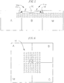
- FIG. 2 shows a diagram of an ESA antenna array with four contiguous line replaceable sub-arrays A-D.
- Each of the sub-arrays A-D includes an array of antenna elements 10.
- sub-array M In a maintenance procedure where, for example, sub-array C is replaced by a spare sub-array M as seen in FIG. 3 , the elements in sub-array M will be out of calibration with respect to the elements of sub-array A, the elements of sub-array B, or the elements of sub-array D, because it can be assumed that sub-array M was not calibrated at the same time, with the same hardware, or in the same relative position in the array as sub-array C.
- sub-array M in the array, mutual coupled measurements to and from elements in neighboring sub-arrays, such as sub-array B and sub-array D can be used to determine correction coefficients required to bring sub-array M into alignment with the rest of the array.
- the polarization of the antenna is linear, uniform, and aligned with the lattice, with the E plane (i.e., the plane of the electric field of the electromagnetic wave) being vertical such that the signals are symmetric around the E polarization.
- the E plane i.e., the plane of the electric field of the electromagnetic wave
- Mutual coupled signals traveling the same distance along symmetric vectors in the electromagnetic field have the same electromagnetic characteristics. This is graphically shown in an exemplary embodiment depicted in FIG. 4 , where antenna array elements 1-8 either transmit or receive a signal as vector ⁇ .
- FIG. 4 illustrates a first sub-array 102 and a second sub-array 104.
- First sub-array 102 includes antenna elements 5, 6, 7, and 8, and second sub-array 104 includes antenna elements 1, 2, 3, and 4.
- element 7 is transmitting signals 12a and 12b as vectors ⁇ to be respectively received by elements 1 and 3.
- element 6 is transmitting signals 12c and 12d as other vectors ⁇ to be respectively received by elements 2 and 4.
- a mutual coupled signal starts with a single element transmitting a signal, which is modified according to the transmitting phase and gain of the transmitting antenna element.
- the transmitted signal travels as a vector ⁇ along a mutual coupling path in the electromagnetic field, which modifies its phase and gain according to the characteristics of the channel, i.e., the mutual coupling characteristics of the mutual coupling path.
- the signal is received by the receiving element, which further modifies the signal in accordance with its receiving phase and gain.
- the signal is then mixed down to its in-phase and quadrature components and reduced to a complex number, capturing both phase and gain information.
- Equations [EQ. 1] and [EQ. 2] below characterize the four signals 12a-12d depicted in FIG. 4 .
- T7 ⁇ R1 represents the signal 12a transmitted from element 7 (with a phase and gain modified by the transmission characteristics of element 7) along vector ⁇ (further modifying the phase and gain according to the characteristics of the channel) and received by element 1 (further modifying the phase and gain according to the receiver characteristics of element 1).
- correction coefficients C1 and C2 can be generated.
- phasing up or calibration of a plurality of antenna elements in the second sub-array 104 is improved by utilizing additional mutual coupled signals along paths ⁇ . That is, as illustrated in FIG. 4 , further signals are transmitted from antenna elements 8 and 7 to antenna elements 1 and 2, respectively, along the mutual coupling paths ⁇ .
- T 8 ⁇ ⁇ ⁇ R 2 T 7 ⁇ ⁇ ⁇ R 1 ⁇ T 7 ⁇ ⁇ ⁇ R 2 T 8 ⁇ ⁇ ⁇ R 1 R 2 R 1 2
- the procedure shown in EQ. 3 is utilized to determine the compensation coefficient for one antenna element in transmit, and one element (not necessarily the same element) in receive, and these compensation coefficients are thereby applied to a plurality of elements in the replaced sub-array M.
- compensation coefficients for a plurality of elements in the replaced sub-array M can be determined, and a global (e.g., an average) compensation coefficient can be generated to bring sub-array M into calibration with the rest of the antenna array.
- FIG. 5 there is shown a typical lattice spacing of antenna elements within three sub-arrays A, B, and M, with an exemplary mutual coupled signal pair transmission of signal vectors 14a and 14b.
- the pair of signals 14a and 14b can be created by transmitting to sub-array A and to sub-array M from the same element 20 in the sub-array B. If there is enough isolation between transmit and receive feeds to allow for mutual coupled element pairs to be in the same sub-array, then mutual coupled path lengths can be shortened (see FIG. 8 , discussed in more detail below) such that neighboring elements within the same sub-array can be used.
- the element 18 should be in a different sub-array than either of the antenna elements 20 and 16 being used to calibrate element 18.
- the receiving elements 16 and 18 are equidistant from the transmitting element 20 and along symmetric electromagnetic field vectors such that the mutual coupling characteristics are the same. Any number of elements may be used to mitigate problems caused by element failures, multipath signals, radome nulls, and other unwanted effects. Further, averaging of compensation characteristics across a number of elements in a replaced sub-array can be utilized to further reduce error effects.
- the resulting signal algebra would look similar to that shown above in [EQ.1] and [EQ.2].
- the resulting complex offset would bring the element 18 in sub-array M into calibration with the element 16 in sub-array A in a receive operation.
- calculation of the average can include calculation of the arithmetic mean, the geometric mean, the median, mode, or any other value resulting from a combination of the plurality of correction coefficients that a designer may find suitable.
- every transmit and receive element has a unique calibration offset such that there is nothing to average, embodiments of the invention enhance calibration of the array as a whole.
- FIG. 6 shows an equivalent diagram to that of FIG. 5 but for a quadrature architecture.
- the signal algebra would be similar to equations [EQ. 1] and [EQ.2] and would provide complex correction coefficients that would align the antenna elements 10 within sub-array M with those of sub-array D.
- sub-array M could be calibrated to sub-array A as well to reduce errors.
- T/R transmit/receive
- other embodiments are utilized to calibrate both active and passive components of a feed network behind the aperture.
- TDUs time delay units
- an embodiment of the invention determines the proper calibration coefficients to apply to the sub-array coupled to that TDU. That is, the new TDU may change the characteristics of the sub-array to which it is attached, such as the amplitude and/or phase.
- a process similar to the process disclosed above for replacement of an antenna sub-array can be utilized to compensate for this change.
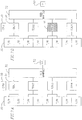
- FIGS. 7A and 7B illustrate another exemplary embodiment of the invention, including a radio frequency (RF) unit 52, a feed manifold 32, a plurality of TDUs 34, a plurality of T/R sub-arrays 30, and a control unit 50.
- the RF unit 52 includes a receiver and an exciter.
- the receiver of the RF unit 52 includes elements such as an amplifier, a mixer, and various RF filters, and converts the received signal into its in-phase and quadrature (I/Q) components, to be processed later.
- I/Q in-phase and quadrature
- an analog to digital (A/D) converter may be utilized for converting the I/Q signals into digital signals for further processing by a DSP.
- the exciter of the RF unit 52 includes elements such as a signal generator and power amplifier for driving the antenna.
- the RF unit 52 is further coupled to a feed manifold 32, which routes RF signals between the RF unit 52 and the TDUs 34, which thereby are coupled to the T/R elements 30.
- control unit 50 is a stand-alone processor, and in other embodiments, the control unit 50 is a beam steering computer for controlling the antenna and steering a beam.
- the control unit 50 may be within the antenna unit, or it may be external to it, combining function with other various tasks as required in an application.
- the control unit 50 may be a microprocessor, a CPU, a state machine, a programmable gate array, or another device for controlling input/output operations of peripheral components and performing calculations, known to those skilled in the art for controlling the calculations of the correction coefficients and for sending and receiving and/or data to or from one or more of the components of the ESA antenna.
- TDUr 36 of FIG. 7B is shown replacing TDU3 of FIG. 7A .
- the resulting need for calibration would be performed in a fashion similar to that depicted in FIGS. 2 and 3 . That is, the determination of compensation coefficients in transmit and/or receive for each of the T/R antenna sub-arrays 30 that are coupled to the replaced TDU 36 would be executed as described above.
- embodiments of the invention are not limited to replacement of a TDU, but rather apply to replacement of any portion of the feed network, such as a cable, an interconnect, or the feed manifold 32.
- alternate embodiments utilize not only calibration of the T/R sub-arrays 30, but if the phase and amplitude characteristics of the TDU are tunable, similar methods may be utilized to calibrate the TDU or other portions of the feed network.
- FIG. 8 illustrates another exemplary embodiment of the present invention, wherein calibration of a replaced sub-array 80 is accomplished with respect to antenna elements within a single calibrated sub-array 82.
- sub-array 82 is configured to have suitable isolation between antenna elements such that the circuit driver that generates a high-power signal transmission from one antenna element substantially does not interfere with the driver circuits for transmission or reception of other antenna elements in the same sub-array 82.
- a signal is transmitted along mutual coupling paths from antenna element 90 in sub-array 82 to antenna elements 88 in sub-array 82 and 84 in sub-array 80.
- antenna element 84 in sub-array 80 in transmit mode, signals are transmitted along mutual coupling paths from antenna 84 in sub-array 80 and from antenna element 88 in sub-array 82 to antenna element 86 in sub-array 82.
- calibration of antenna element 84 in sub-array 80 can be accomplished in both transmit and receive modes relative to antenna elements 86, 88, and 90, each within the same sub-array 82.
Landscapes
- Variable-Direction Aerials And Aerial Arrays (AREA)
Description
- The present invention relates to the field of antennas, and more particularly, to the field repair and replacement of phased array antennas.
- For phased array antennas, such as electronically scanned array (ESA) antennas, there is an emerging requirement to utilize modular arrays, in which standardized units or portions of the antenna (e.g., sub-arrays or a radio frequency (RF) feed network) are replaceable in the field as part of mission support. Driving this requirement is the desire to simplify and reduce the cost of repair or replacement of part of the antenna, for example, by reducing the size and cost of spares. Further, after replacement, the phase and amplitude of the antenna elements of a newly replaced sub-array, or those corresponding to a newly replaced feed network, must be calibrated (a process typically called phase-up). Thus, there is a desire in the art to eliminate the need to remove the entire antenna from the platform and either utilize special test equipment (STE) in the field or return it to the factory for recalibration or phase-up.
- One conventional approach utilizes near field techniques through the use of a portable RF absorber aperture cover with an embedded horn feeding a network analyzer. The cover is placed over the aperture and a coarse measurement of the phase and gain of the replaced elements is made and used to align the new elements to the rest of the array. Another similar technique has horn antennas mounted on the edges of the aperture and the signals are processed within the system.
- Still another approach is taught in
U.S. Patent 5,657,023 issued to Lewis et al. , the entire content of which is incorporated herein by reference. Lewis provides for phase-up of array antennas of a regularly spaced lattice orientation, without the use of a nearfield or farfield range. The technique uses mutual coupling and/or reflections to provide a signal from one element to its neighbors. This signal provides a reference to allow for each antenna element to be phased-up with respect to one another. - Referring to
FIG. 1A , as taught in Lewis et al., a line array includes antenna elements 1-5. The sequence begins by transmitting fromelement 1 as shown inFIG. 1A as transmission T1, and simultaneously receiving a measurement signal R inelement 2. A signal T2 is then transmitted fromelement 3, and a measurement signal is received inelement 2. The phase and gain response fromelement 2 in this case (reception of the transmitted signal from element 3) is compared to that for the previous measurement (reception of the transmitted signal from element 1). This allows the transmit phase/gain differences betweenelements element 3, a receive measurement is then made throughelement 4. The differences in receive phase/gain response forelements - To finish the example depicted in
FIG. 1A , a signal T3 is transmitted fromelement 5 and a receive signal is measured inelement 4. Data from this measurement allowselement 5 transmit phase/gain coefficients to be calculated with respect to transmit excitations forelements - The result of this series of measurements is computation of correction coefficients that when applied allow
elements elements - In a line array of arbitrary extent, the measurement sequences of transmitting from every element and making receive measurements from adjacent elements continues to the end of the array. Thus the calibration technique can be applied to arbitrarily sized arrays. Receive measurements using elements other than those adjacent to the transmitting elements may also be used. These additional receive measurements can lead to reduced overall measurement time and increased measurement accuracy.
- For an odd element receive phase-up the second series of measurements is aimed at phasing up the odd numbered elements in receive and even numbered elements in transmit. These measurement sequences are similar to those described above for the even element phase-up, and are illustrated in
FIG. 1B . - First, a transmit signal from
element 2 provides excitation for receive measurements fromelement 1 and thenelement 3. This allows the relative receive phase/gain responses ofelements - A transmit signal from
element 4 is then used to make receive measurements fromelement 3 and thenelement 5. This allows the relative receive phase/gain response ofelements element 4 with respect toelement 2 can be calculated. All of the coefficients can then be used to provide a receive phase-up of the even elements and a transmit phase-up of the odd elements. - To complete the overall phase-up utilizing conventional practices, the interleaved phased-up odd-even elements need to be brought into overall phase/gain alignment. Coefficients are determined, which, when applied, achieve this alignment.
- However, in accordance with the technique described in Lewis et al. each individual antenna element is measured and calibrated, which can be time consuming and energy wasting.
-
US 5,864,317 discloses a quadrant-partitioned array architecture and measurement sequence supporting mutual-coupling based calibration. -
EP 1670095 discloses a method for calibrating a phase array antenna comprising performing initial measurements of array antenna elements to ensure that calibration measurements are within the linear dynamic range of receive elements contained within the array. - Aumann H M et al: "Phased Array Antenna Calibration and Pattern Prediction Using Mutual Coupling Measurements", IEEE Transactions of Antennas and Propagation, IEEE Service Center, Piscataway, NJ, US, investigates a technique which utilizes the inherent mutual coupling in an array to both calibrate and predict the radiation patterns of a phased array antenna.
- The present invention provides a method for calibrating a modular phased array antenna according to claim 1 hereafter, and an electronically scanned array antenna according to claim 13 hereafter.
- The present invention utilizes mutual coupled signals that are transmitted and received between one array element in an uncalibrated sub-array to another array element in another (already calibrated) sub-array to provide measurements of the phase and gain of antenna elements in the uncalibrated sub-array. Calibration offsets derived through this method then provide system level calibration regardless of which antenna sub-array or RF component of the antenna array is replaced.
- Mutual coupled element to element calibration is used for measuring elemental phase and gain to calibrate an entire portion (i.e., sub-array) of the antenna array replaced in the field without an RF absorber cover, peripheral horns, or any external test equipment. It also provides calibration for other RF components in the antenna so they can be replaced in the field as part of mission support.
- Embodiments of the present invention provide both significant cost savings in field calibration and during factory/depot test. Embodiments of the present invention can also be extended to the calibration of hardware between the antenna output and receiver input, such as switch assemblies and cables. Repair and replacement of failed units without the use of special field test equipment is a key requirement of most new radar developments.
- In accordance with one exemplary embodiment of the present invention, a modular phased array antenna includes a plurality of sub-arrays, each of the sub-arrays having a plurality of antenna elements. First, a correction coefficient is determined for calibrating a first antenna element of the antenna elements in the first sub-array. The correction coefficient is then applied to a plurality of the antenna elements in the sub-array, for example, each of the antenna elements in the sub-array.
- In some embodiments, the method is applied after replacement of the first sub-array. In other embodiments, the method is applied after replacement of other components, such as part or parts of a feed network (e.g., a time delay unit) providing signals to/from the first sub-array.
- In a further exemplary embodiment, the determination of the correction coefficient includes first determining intermediate correction coefficients for each of a plurality of the antenna elements in the first sub-array, and then calculating an average correction coefficient corresponding to those intermediate correction coefficients. The average correction coefficient is then applied to a plurality (e.g., each) of the antenna elements in the first sub-array.
- In a further exemplary embodiment, in the first sub-array, a first antenna element has a first receiving phase and gain and a first transmitting phase and gain. Second and third sub-arrays also include antenna elements having their own respective transmitting and receiving phase and gain. To determine a receiving correction coefficient for calibrating the first sub-array in a receive mode, the correction coefficient (i.e., the receiving correction coefficient) is determined by transmitting signals along mutual coupling paths, each having respective mutual coupling characteristics (e.g., each mutual coupling path having equivalent mutual coupling characteristics), from the second sub-array to each of the third sub-array and the first sub-array. The receiving correction coefficient then corresponds to a difference between characteristics of the signal received by the first sub-array, which is to be calibrated, and the third sub-array, which is assumed to already be in calibration. The receiving correction coefficient may then be applied to a plurality (e.g., each) of the antenna elements in the first sub-array.
- In an even further exemplary embodiment, the signals transmitted along the mutual coupling paths from the second sub-array to the first and third sub-arrays correspond to changes in an amplitude and a phase of the signals sent to the second sub-array, those changes corresponding to the transmitting phase and gain of the transmitting antenna element of the second sub-array, the mutual coupling characteristics of the respective mutual coupling paths, and the receiving phase and gain of the respective receiving antenna elements of the first and third sub-arrays.
- In another embodiment for determining a transmitting correction coefficient for the first sub-array, the first sub-array and a fourth sub-array respectively transmit signals along mutual coupling paths to a fifth sub-array. The transmitting correction coefficient thereby corresponds to a difference between the signal received at the fifth sub-array from the first sub-array and the one received from the fourth sub-array. The transmitting correction coefficient may then be applied to a plurality (e.g., each) of the antenna elements in the first sub-array.
-
-
FIGS. 1A and 1B show a conventional transmit and receive calibration of a linear antenna array. -
FIGS. 2 and 3 show a modular electronically scanned array antenna being recalibrated in accordance with an exemplary embodiment of the present invention. -
FIG. 4 shows mutual coupled signal representations in accordance with an exemplary embodiment of the present invention. -
FIG. 5 shows mutual coupled signal representations in accordance with an exemplary embodiment of the present invention for linearly adjacent sub-arrays. -
FIG. 6 shows mutual coupled signal representation in accordance with an exemplary embodiment of the present invention for quadraturely adjacent sub-arrays. -
FIGS. 7A and 7B show an alternative replacement configuration in accordance with an exemplary embodiment of the present invention. -
FIG. 8 shows mutual coupled signal representations for recalibration of an antenna having high isolation between antenna elements according to an exemplary embodiment of the present invention. - Given a modular electronically scanned array (ESA) or phased array antenna with an architecture having standardized units or components of the antenna that are replaceable with spare components, after replacement the antenna generally requires recalibration. For example, an antenna array may include multiple sub-arrays, each including a number of antenna elements, wherein the sub-arrays are field replaceable. Moreover, a feed network or other components coupled to the sub-arrays may be replaceable in the field. In many cases the replacement of any of these components can bring the sub-array to which they are coupled out of calibration.
- In conventional systems for recalibration of ESAs utilizing mutual coupling, it was assumed that every antenna element required calibration. Thus, conventional systems suffered from an increased computational load, more required power, an increased calibration time, and an increased use of the hardware, potentially reducing its lifetime. Embodiments of the invention achieve calibration of the whole array in the field utilizing only one element, or a subset of the elements in the replaced sub-array to determine the offset required to align the global phase and amplitude of the sub-arrays.
- In accordance with an exemplary embodiment of the present invention, mutual coupled measurements are utilized to calibrate a replaced (or otherwise out of calibration) sub-array in accordance with the rest of the array during a field maintenance procedure without requiring external special test equipment (STE).
FIG. 2 shows a diagram of an ESA antenna array with four contiguous line replaceable sub-arrays A-D. Each of the sub-arrays A-D includes an array ofantenna elements 10. - In a maintenance procedure where, for example, sub-array C is replaced by a spare sub-array M as seen in
FIG. 3 , the elements in sub-array M will be out of calibration with respect to the elements of sub-array A, the elements of sub-array B, or the elements of sub-array D, because it can be assumed that sub-array M was not calibrated at the same time, with the same hardware, or in the same relative position in the array as sub-array C. - With sub-array M in the array, mutual coupled measurements to and from elements in neighboring sub-arrays, such as sub-array B and sub-array D can be used to determine correction coefficients required to bring sub-array M into alignment with the rest of the array.
- In accordance with an exemplary embodiment of the present invention, the polarization of the antenna is linear, uniform, and aligned with the lattice, with the E plane (i.e., the plane of the electric field of the electromagnetic wave) being vertical such that the signals are symmetric around the E polarization. Mutual coupled signals traveling the same distance along symmetric vectors in the electromagnetic field have the same electromagnetic characteristics. This is graphically shown in an exemplary embodiment depicted in
FIG. 4 , where antenna array elements 1-8 either transmit or receive a signal as vector γ. -
FIG. 4 illustrates afirst sub-array 102 and asecond sub-array 104. First sub-array 102 includesantenna elements second sub-array 104 includesantenna elements element 7 is transmittingsignals elements element 6 is transmittingsignals elements - A mutual coupled signal starts with a single element transmitting a signal, which is modified according to the transmitting phase and gain of the transmitting antenna element. The transmitted signal travels as a vector γ along a mutual coupling path in the electromagnetic field, which modifies its phase and gain according to the characteristics of the channel, i.e., the mutual coupling characteristics of the mutual coupling path. Then the signal is received by the receiving element, which further modifies the signal in accordance with its receiving phase and gain. The signal is then mixed down to its in-phase and quadrature components and reduced to a complex number, capturing both phase and gain information.
- It is convenient to represent any mutual coupled signal graphically by the three components that affect the signal. Equations [EQ. 1] and [EQ. 2] below characterize the four
signals 12a-12d depicted inFIG. 4 . For example, "T7 γ R1" represents thesignal 12a transmitted from element 7 (with a phase and gain modified by the transmission characteristics of element 7) along vector γ (further modifying the phase and gain according to the characteristics of the channel) and received by element 1 (further modifying the phase and gain according to the receiver characteristics of element 1). Using signal algebra as taught in Lewis et al. to determine the necessary complex math, correction coefficients C1 and C2 can be generated.

- The simplified signal algebra of [EQ.1] and [EQ.2] shows the generation of correction coefficients C1 and C2, which can be applied to
element number 3 inFIG. 4 to bring it into phase and gain alignment in receive withelement number 1, and similarly, for phasing upelement 4 toelement 2 in receive. That is, to bringelement 3 into calibration withelement 1 in receive, the correction coefficient C1 is applied toelement 3 in the following fashion when signals are received by element 3:
- In some embodiments of the invention, phasing up or calibration of a plurality of antenna elements in the second sub-array 104 (e.g., the entire sub-array 104) is improved by utilizing additional mutual coupled signals along paths α. That is, as illustrated in
FIG. 4 , further signals are transmitted fromantenna elements antenna elements 
- As is seen in EQ. 4, by utilizing the signals along the mutual coupling paths α between
antenna elements antenna elements elements elements element 1 becomes a reference element, so that elements 2-4 can be calibrated in accordance withelement 1. - In some embodiments of the invention, to expedite calibration, the procedure shown in EQ. 3 is utilized to determine the compensation coefficient for one antenna element in transmit, and one element (not necessarily the same element) in receive, and these compensation coefficients are thereby applied to a plurality of elements in the replaced sub-array M. In other embodiments, compensation coefficients for a plurality of elements in the replaced sub-array M can be determined, and a global (e.g., an average) compensation coefficient can be generated to bring sub-array M into calibration with the rest of the antenna array.
- Referring now to
FIG. 5 , there is shown a typical lattice spacing of antenna elements within three sub-arrays A, B, and M, with an exemplary mutual coupled signal pair transmission ofsignal vectors signals same element 20 in the sub-array B. If there is enough isolation between transmit and receive feeds to allow for mutual coupled element pairs to be in the same sub-array, then mutual coupled path lengths can be shortened (seeFIG. 8 , discussed in more detail below) such that neighboring elements within the same sub-array can be used. Of course, theelement 18 should be in a different sub-array than either of theantenna elements element 18. - The receiving
elements element 20 and along symmetric electromagnetic field vectors such that the mutual coupling characteristics are the same. Any number of elements may be used to mitigate problems caused by element failures, multipath signals, radome nulls, and other unwanted effects. Further, averaging of compensation characteristics across a number of elements in a replaced sub-array can be utilized to further reduce error effects. - The resulting signal algebra would look similar to that shown above in [EQ.1] and [EQ.2]. The resulting complex offset would bring the
element 18 in sub-array M into calibration with theelement 16 in sub-array A in a receive operation. - To calibrate the replaced sub-array for a transmit operation, a process similar to a reverse of the above process is utilized. That is, to bring
element 18 into calibration in transmission,elements element 20 receives the mutual coupled signals fromelements element 18 relative toelement 16 can be determined corresponding to the mutual coupled signals received fromelements element 20. Thereafter, as discussed above, a calculated correction coefficient is applied toelement 18 in transmit to bring it into calibration in transmission relative toelement 16. - Improved accuracy for the calibration coefficient in either transmit or receive modes is achieved by utilizing multiple measurements as described above with many element pairs, and averaging the results to mitigate errors and unwanted effects. According to various embodiments, calculation of the average can include calculation of the arithmetic mean, the geometric mean, the median, mode, or any other value resulting from a combination of the plurality of correction coefficients that a designer may find suitable. Thus, in contrast to the prior art, in which every transmit and receive element has a unique calibration offset such that there is nothing to average, embodiments of the invention enhance calibration of the array as a whole.
- Another exemplary embodiment of the present invention can be applied to an antenna with a quadrature style sub-array architecture.
FIG. 6 shows an equivalent diagram to that ofFIG. 5 but for a quadrature architecture. Again, the signal algebra would be similar to equations [EQ. 1] and [EQ.2] and would provide complex correction coefficients that would align theantenna elements 10 within sub-array M with those of sub-array D. Using other symmetries, sub-array M could be calibrated to sub-array A as well to reduce errors. - Further, while some embodiments of the present invention are utilized to calibrate pieces of the front of the antenna array, that is, the transmit/receive (T/R) antenna sub-arrays, other embodiments are utilized to calibrate both active and passive components of a feed network behind the aperture. For example, an architecture that contains time delay units (TDUs) could require the replacement of one TDU in the field. Thus, an embodiment of the invention determines the proper calibration coefficients to apply to the sub-array coupled to that TDU. That is, the new TDU may change the characteristics of the sub-array to which it is attached, such as the amplitude and/or phase. Thus, a process similar to the process disclosed above for replacement of an antenna sub-array can be utilized to compensate for this change.
-
FIGS. 7A and 7B illustrate another exemplary embodiment of the invention, including a radio frequency (RF)unit 52, afeed manifold 32, a plurality ofTDUs 34, a plurality of T/R sub-arrays 30, and acontrol unit 50. TheRF unit 52 includes a receiver and an exciter. In some embodiments, the receiver of theRF unit 52 includes elements such as an amplifier, a mixer, and various RF filters, and converts the received signal into its in-phase and quadrature (I/Q) components, to be processed later. For example, an analog to digital (A/D) converter may be utilized for converting the I/Q signals into digital signals for further processing by a DSP. In some embodiments, the exciter of theRF unit 52 includes elements such as a signal generator and power amplifier for driving the antenna. TheRF unit 52 is further coupled to afeed manifold 32, which routes RF signals between theRF unit 52 and theTDUs 34, which thereby are coupled to the T/R elements 30. - According to some embodiments, the
control unit 50 is a stand-alone processor, and in other embodiments, thecontrol unit 50 is a beam steering computer for controlling the antenna and steering a beam. Thecontrol unit 50 may be within the antenna unit, or it may be external to it, combining function with other various tasks as required in an application. Thecontrol unit 50 may be a microprocessor, a CPU, a state machine, a programmable gate array, or another device for controlling input/output operations of peripheral components and performing calculations, known to those skilled in the art for controlling the calculations of the correction coefficients and for sending and receiving and/or data to or from one or more of the components of the ESA antenna. -
TDUr 36 ofFIG. 7B is shown replacing TDU3 ofFIG. 7A . As such, the resulting need for calibration would be performed in a fashion similar to that depicted inFIGS. 2 and 3 . That is, the determination of compensation coefficients in transmit and/or receive for each of the T/R antenna sub-arrays 30 that are coupled to the replacedTDU 36 would be executed as described above. One skilled in the art will comprehend that embodiments of the invention are not limited to replacement of a TDU, but rather apply to replacement of any portion of the feed network, such as a cable, an interconnect, or thefeed manifold 32. Further, alternate embodiments utilize not only calibration of the T/R sub-arrays 30, but if the phase and amplitude characteristics of the TDU are tunable, similar methods may be utilized to calibrate the TDU or other portions of the feed network. -
FIG. 8 illustrates another exemplary embodiment of the present invention, wherein calibration of a replacedsub-array 80 is accomplished with respect to antenna elements within a single calibratedsub-array 82. In this embodiment, sub-array 82 is configured to have suitable isolation between antenna elements such that the circuit driver that generates a high-power signal transmission from one antenna element substantially does not interfere with the driver circuits for transmission or reception of other antenna elements in thesame sub-array 82. Thus, to calibrateantenna element 84 insub-array 80 in receive mode, a signal is transmitted along mutual coupling paths fromantenna element 90 insub-array 82 toantenna elements 88 insub-array sub-array 80. Similarly, to calibrateantenna element 84 insub-array 80 in transmit mode, signals are transmitted along mutual coupling paths fromantenna 84 insub-array 80 and fromantenna element 88 insub-array 82 toantenna element 86 insub-array 82. Thereby, utilizing the methods described above, calibration ofantenna element 84 insub-array 80 can be accomplished in both transmit and receive modes relative toantenna elements same sub-array 82. - Although the present invention has been described with reference to the exemplary embodiments thereof, it will be appreciated by those skilled in the art that it is possible to modify and change the present invention in various ways without departing from the scope of the present invention as set forth in the following claims. For example, any cable, set of cables, or the feed manifold itself could be replaced and recalibrated in the field using the approach in accordance with the present invention.
Claims (13)
- A method of calibrating a modular phased array antenna after replacement of a sub-array of the modular phased array antenna, the modular phased array antenna comprising a replaced pre-calibrated sub-array, and a plurality of sub-arrays (102, 104), each sub-array of the plurality of sub-arrays comprising a plurality of antenna elements (1, 2, 3, 4, 5, 6, 7, 8), the method comprising:determining a complex correction coefficient for correcting a phase and an amplitude of a first antenna element of the plurality of antenna elements in the replaced sub-array of the plurality of sub-arrays using mutual coupled measurements to and from elements in neighboring sub-arrays;applying the determined correction coefficient to each of the antenna elements in the first sub-array to align the global phase and amplitude of the sub-arrays.
- The method of claim 1, wherein the first antenna element comprises a time delay unit, TDU, (34) coupled to the replaced sub-array (102, 104), wherein the TDU is configured to change characteristics of the replaced sub-array (102, 104).
- The method of claim 1, wherein:the determining the correction coefficient comprises:determining first correction coefficients for each of a first plurality of the antenna elements (1, 2, 3, 4, 5, 6, 7, 8) in the replaced sub-array (102, 104); andcalculating an average correction coefficient corresponding to the first correction coefficients, and wherein:the applying the correction coefficient comprises applying the average correction coefficient to each of the antenna elements in the replaced sub-array.
- The method of claim 1, wherein:the first antenna element of the replaced sub-array has a first receiving phase and gain and a first transmitting phase and gain;a second sub-array of the sub-arrays comprises a second antenna element of the antenna elements, the second antenna element having a second transmitting phase and gain; anda third sub-array of the sub-arrays comprises a third antenna element of the antenna elements, the third antenna element having a third receiving phase and gain, the first sub-array being a different sub-array other than the second sub-array and the third sub-array,wherein the determining of the correction coefficient comprises:transmitting a first signal along a first mutual coupling path having a first mutual coupling characteristic from the second antenna element to the third antenna element, and along a second mutual coupling path having a second mutual coupling characteristic from the second antenna element to the first antenna element; anddetermining a receiving correction coefficient for the first antenna element corresponding to a difference between the first signal received by the first antenna element and the first signal received by the third antenna element.
- The method of claim 4, wherein the first mutual coupling characteristic is substantially identical to the second mutual coupling characteristic.
- The method of claim 5, wherein the applying of the correction coefficient comprises applying the receiving correction coefficient to the first plurality of the antenna elements (1, 2, 3, 4, 5, 6, 7, 8) in the first sub-array (102, 104).
- The method of claim 4, wherein the second sub-array (102, 104) is a different sub-array other than the third sub-array.
- The method of claim 4, wherein:the first signal received by the first antenna element (1, 2, 3, 4, 5, 6, 7, 8) corresponds to changes in an amplitude and a phase of the first signal corresponding to a change of phase and a change of gain caused by each of the second transmitting phase and gain, the first mutual coupling characteristic, and the first receiving phase and gain; andthe first signal received by the third antenna element (1, 2, 3, 4, 5, 6, 7, 8) corresponds to changes in an amplitude and a phase of the first signal corresponding to a change of phase and a change of gain caused by each of the second transmitting phase and gain, the second mutual coupling characteristic, and the third receiving phase and gain.
- The method of claim 8, wherein the first mutual coupling characteristic is substantially identical to the second mutual coupling characteristic.
- The method of claim 4, wherein:a fourth sub-array of the sub-arrays comprises a fourth antenna element of the antenna elements, the fourth antenna element having a fourth transmitting phase and gain; anda fifth sub-array of the sub-arrays comprises a fifth antenna element of the antenna elements, the fifth antenna element having a fifth receiving phase and gain, the first sub-array being a different sub-array other than the fourth sub-array and the fifth sub-array,wherein the determining the correction coefficient further comprises:transmitting a second signal along a third mutual coupling path having a third mutual coupling characteristic from the fourth antenna element to the fifth antenna element;transmitting a third signal along a fourth mutual coupling path having a fourth mutual coupling characteristic from the first antenna element to the fifth antenna element; anddetermining a transmitting correction coefficient for the first antenna element corresponding to a difference between the second signal received by the fifth antenna element and the third signal received by the fifth antenna element.
- The method of claim 10, wherein applying the correction coefficient comprises applying the transmitting correction coefficient to the first plurality of the antenna elements in the first sub-array.
- The method of claim 10, wherein:the second signal received by the fifth antenna element corresponds to changes in an amplitude and a phase of the second signal corresponding to a change of phase and a change of gain caused by each of the fourth transmitting phase and gain, the second mutual coupling characteristic, and the fifth receiving phase and gain; andthe third signal received by the fifth antenna element corresponds to changes in an amplitude and a phase of the third signal corresponding to a change of phase and a change of gain caused by each of the first transmitting phase and gain, the third mutual coupling characteristic, and the fifth receiving phase and gain.
- An electronically scanned array antenna comprising:an antenna array comprising a replaced pre-calibrated sub-array, and a plurality of sub-arrays (102, 104), each sub-array comprising a plurality of antenna elements (1, 2,3,4,5,6,7,8);a feed network for transmitting signals to or from respective ones of the sub-arrays; anda control unit (50) for determining a complex correction coefficient for correcting a phase and an amplitude of a first antenna element of the antenna elements in the replaced sub-array of the plurality of sub-arrays using mutual coupled measurements to and from elements in neighboring sub-arrays, the control unit configured to apply the determined complex correction coefficient to each of the antenna elements in the first sub-array to align the global phase and amplitude of the sub-arrays.
Applications Claiming Priority (1)
| Application Number | Priority Date | Filing Date | Title |
|---|---|---|---|
| US12/499,765 US8154452B2 (en) | 2009-07-08 | 2009-07-08 | Method and apparatus for phased array antenna field recalibration |
Publications (2)
| Publication Number | Publication Date |
|---|---|
| EP2273614A1 EP2273614A1 (en) | 2011-01-12 |
| EP2273614B1 true EP2273614B1 (en) | 2017-12-27 |
Family
ID=43012714
Family Applications (1)
| Application Number | Title | Priority Date | Filing Date |
|---|---|---|---|
| EP10251208.4A Active EP2273614B1 (en) | 2009-07-08 | 2010-07-06 | Method and apparatus for phased array antenna field recalibration |
Country Status (2)
| Country | Link |
|---|---|
| US (1) | US8154452B2 (en) |
| EP (1) | EP2273614B1 (en) |
Families Citing this family (42)
| Publication number | Priority date | Publication date | Assignee | Title |
|---|---|---|---|---|
| US8170510B2 (en) * | 2009-05-29 | 2012-05-01 | Intel Mobile Communications GmbH | Minimizing mutual coupling |
| US20110122026A1 (en) * | 2009-11-24 | 2011-05-26 | Delaquil Matthew P | Scalable and/or reconfigurable beamformer systems |
| US8311166B2 (en) | 2010-03-31 | 2012-11-13 | Ubidyne, Inc. | Active antenna array and method for calibration of the active antenna array |
| US8441966B2 (en) | 2010-03-31 | 2013-05-14 | Ubidyne Inc. | Active antenna array and method for calibration of receive paths in said array |
| US8340612B2 (en) * | 2010-03-31 | 2012-12-25 | Ubidyne, Inc. | Active antenna array and method for calibration of the active antenna array |
| JP5620757B2 (en) * | 2010-09-01 | 2014-11-05 | 株式会社豊田中央研究所 | Radar equipment |
| JP5104938B2 (en) * | 2010-12-09 | 2012-12-19 | 株式会社デンソー | Phased array antenna phase calibration method and phased array antenna |
| US20120196545A1 (en) * | 2011-01-28 | 2012-08-02 | Georg Schmidt | Antenna array and method for synthesizing antenna patterns |
| US8686896B2 (en) * | 2011-02-11 | 2014-04-01 | Src, Inc. | Bench-top measurement method, apparatus and system for phased array radar apparatus calibration |
| US9124361B2 (en) * | 2011-10-06 | 2015-09-01 | Raytheon Company | Scalable, analog monopulse network |
| FR2981513B1 (en) * | 2011-10-14 | 2015-05-15 | Thales Sa | SIMPLIFIED METHOD FOR UPDATING THE CALIBRATION OF A HYPERFREQUENCY DEVICE FOLLOWING A MAINTENANCE OPERATION |
| US9409151B1 (en) * | 2012-08-29 | 2016-08-09 | Rockwell Collins, Inc. | Calibration and optimization of ESA in aircraft radomes |
| US8564497B1 (en) | 2012-08-31 | 2013-10-22 | Redline Communications Inc. | System and method for payload enclosure |
| US20150349420A1 (en) * | 2014-02-13 | 2015-12-03 | The United States Of America As Represented By The Secretary Of The Navy | Planar near-field calibration of digital arrays using element plane wave spectra |
| US10109915B2 (en) * | 2014-02-13 | 2018-10-23 | The United States Of America As Represented By The Secretary Of The Navy | Planar near-field calibration of digital arrays using element plane wave spectra |
| US10056685B2 (en) * | 2014-03-06 | 2018-08-21 | Samsung Electronics Co., Ltd. | Antenna array self-calibration |
| US9331751B2 (en) * | 2014-08-05 | 2016-05-03 | Raytheon Company | Method and system for characterizing an array antenna using near-field measurements |
| US9614279B2 (en) | 2014-08-11 | 2017-04-04 | Raytheon Company | Portable apparatus and associated method for phased array field calibration |
| US9866336B2 (en) | 2015-06-17 | 2018-01-09 | Google Llc | Phased array antenna self-calibration |
| KR102422396B1 (en) * | 2015-09-01 | 2022-07-20 | 주식회사 에이치엘클레무브 | Method of spatial interpolation for linear phased array antenna and appratus thereof |
| US10225067B2 (en) | 2015-09-10 | 2019-03-05 | Blue Danube Systems, Inc. | Active array calibration |
| US20170181166A1 (en) * | 2015-12-18 | 2017-06-22 | Qualcomm Incorporated | Run Time Radio Frequency Calibration for Receive Chains in Mobile Devices |
| US10103431B2 (en) * | 2016-04-21 | 2018-10-16 | Google Llc | Phased array antenna calibration |
| US9948407B2 (en) * | 2016-05-27 | 2018-04-17 | Huawei Technologies Co., Ltd. | Method and apparatus for beamforming calibration in point to multipoint communication systems |
| EP3439214B1 (en) * | 2017-01-09 | 2023-11-08 | LG Electronics Inc. | Method for reporting channel state information in wireless communication system, and device therefor |
| US10523345B2 (en) * | 2017-03-06 | 2019-12-31 | Samsung Electronics Co., Ltd. | Methods and apparatus for calibration and array operation in advanced MIMO system |
| PL3596780T3 (en) | 2017-03-13 | 2022-01-31 | Telefonaktiebolaget Lm Ericsson (Publ) | Self-calibration of antenna array system |
| US10431877B2 (en) | 2017-05-12 | 2019-10-01 | Commscope Technologies Llc | Base station antennas having parasitic coupling units |
| EP3682508B1 (en) | 2017-09-15 | 2021-11-03 | Telefonaktiebolaget LM Ericsson (publ) | Systems and methods for self-calibration of an analog beamforming transceiver |
| WO2019060287A1 (en) * | 2017-09-20 | 2019-03-28 | Commscope Technologies Llc | Methods for calibrating millimeter wave antenna arrays |
| US10148367B1 (en) * | 2017-12-22 | 2018-12-04 | Raytheon Company | Built-in-test (BIT) for assignment-based AESA systems |
| US10425172B2 (en) | 2017-12-22 | 2019-09-24 | Raytheon Company | Clutter rejecting built in test for assignment-based AESA systems |
| US11177567B2 (en) * | 2018-02-23 | 2021-11-16 | Analog Devices Global Unlimited Company | Antenna array calibration systems and methods |
| GB2579175B (en) * | 2018-11-01 | 2021-01-06 | Leonardo Mw Ltd | An active array antenna with sub-arrays and a method for its calibration |
| US11349208B2 (en) | 2019-01-14 | 2022-05-31 | Analog Devices International Unlimited Company | Antenna apparatus with switches for antenna array calibration |
| US11404779B2 (en) | 2019-03-14 | 2022-08-02 | Analog Devices International Unlimited Company | On-chip phased array calibration systems and methods |
| WO2020190863A1 (en) | 2019-03-21 | 2020-09-24 | Commscope Technologies Llc | Base station antennas having parasitic assemblies for improving cross-polarization discrimination performance |
| EP3843212A1 (en) * | 2019-12-24 | 2021-06-30 | Pharrowtech | Phased array module |
| KR102479054B1 (en) | 2020-01-30 | 2022-12-20 | 한국전자통신연구원 | Array antenna system, calibration method and apparatus for thereof |
| US11450952B2 (en) | 2020-02-26 | 2022-09-20 | Analog Devices International Unlimited Company | Beamformer automatic calibration systems and methods |
| US10979152B1 (en) * | 2020-03-05 | 2021-04-13 | Rockwell Collins, Inc. | Conformal ESA calibration |
| US11394115B2 (en) * | 2020-06-22 | 2022-07-19 | Mixcomm, Inc. | Array calibration thru polarization cross-coupling |
Family Cites Families (45)
| Publication number | Priority date | Publication date | Assignee | Title |
|---|---|---|---|---|
| FR2659501B1 (en) * | 1990-03-09 | 1992-07-31 | Alcatel Espace | HIGH EFFICIENCY PRINTED ACTIVE ANTENNA SYSTEM FOR AGILE SPATIAL RADAR. |
| US5122806A (en) | 1990-05-31 | 1992-06-16 | Hughes Aircraft Company | Method for finding defective active array modules using an FFT over phase states |
| FR2696553B1 (en) | 1992-10-01 | 1994-11-25 | Alcatel Espace | Near field antenna calibration method for active antenna. |
| US5530449A (en) | 1994-11-18 | 1996-06-25 | Hughes Electronics | Phased array antenna management system and calibration method |
| US5644316A (en) | 1996-05-02 | 1997-07-01 | Hughes Electronics | Active phased array adjustment using transmit amplitude adjustment range measurements |
| US5682165A (en) | 1996-05-02 | 1997-10-28 | Hughes Electronics | Active array self calibration |
| US5657023A (en) | 1996-05-02 | 1997-08-12 | Hughes Electronics | Self-phase up of array antennas with non-uniform element mutual coupling and arbitrary lattice orientation |
| US5933113A (en) * | 1996-09-05 | 1999-08-03 | Raytheon Company | Simultaneous multibeam and frequency active photonic array radar apparatus |
| US6900775B2 (en) | 1997-03-03 | 2005-05-31 | Celletra Ltd. | Active antenna array configuration and control for cellular communication systems |
| SE509434C2 (en) | 1997-05-16 | 1999-01-25 | Ericsson Telefon Ab L M | Antenna calibration device and method |
| US5864317A (en) | 1997-05-23 | 1999-01-26 | Raytheon Company | Simplified quadrant-partitioned array architecture and measure sequence to support mutual-coupling based calibration |
| US5929810A (en) | 1997-12-19 | 1999-07-27 | Northrop Grumman Corporation | In-flight antenna optimization |
| DE19806914C2 (en) | 1998-02-19 | 2002-01-31 | Bosch Gmbh Robert | Method and device for calibrating a group antenna |
| US6208287B1 (en) | 1998-03-16 | 2001-03-27 | Raytheoncompany | Phased array antenna calibration system and method |
| US6252542B1 (en) | 1998-03-16 | 2001-06-26 | Thomas V. Sikina | Phased array antenna calibration system and method using array clusters |
| US5929809A (en) | 1998-04-07 | 1999-07-27 | Motorola, Inc. | Method and system for calibration of sectionally assembled phased array antennas |
| US6615024B1 (en) | 1998-05-01 | 2003-09-02 | Arraycomm, Inc. | Method and apparatus for determining signatures for calibrating a communication station having an antenna array |
| US6133868A (en) | 1998-06-05 | 2000-10-17 | Metawave Communications Corporation | System and method for fully self-contained calibration of an antenna array |
| US6157340A (en) * | 1998-10-26 | 2000-12-05 | Cwill Telecommunications, Inc. | Adaptive antenna array subsystem calibration |
| US6084545A (en) | 1999-07-12 | 2000-07-04 | Lockheed Martin Corporation | Near-field calibration system for phase-array antennas |
| EP1120858B1 (en) | 1999-12-15 | 2007-04-04 | Nippon Telegraph and Telephone Corporation | Adaptive array transceiver apparatus |
| US6707419B2 (en) | 2000-08-16 | 2004-03-16 | Raytheon Company | Radar transmitter circuitry and techniques |
| US6356233B1 (en) | 2000-12-12 | 2002-03-12 | Lockheed Martin Corporation | Structure for an array antenna, and calibration method therefor |
| US6417769B1 (en) | 2001-03-27 | 2002-07-09 | Te-Chin Jan | Voice-controlled burglarproof device |
| US6522296B2 (en) | 2001-06-25 | 2003-02-18 | Harris Corporation | Method and system for calibrating wireless location systems |
| US6738020B1 (en) | 2001-07-31 | 2004-05-18 | Arraycomm, Inc. | Estimation of downlink transmission parameters in a radio communications system with an adaptive antenna array |
| KR100444822B1 (en) | 2001-08-07 | 2004-08-18 | 한국전자통신연구원 | Apparatus for Calibration in Adaptive Array Antenna and Method Thereof |
| US6667713B2 (en) | 2001-08-24 | 2003-12-23 | Spectrum Astro | Self-monitoring satellite system |
| JP2005502250A (en) | 2001-08-31 | 2005-01-20 | ザ トラスティーズ オブ コロムビア ユニバーシティ イン ザ シティ オブ ニューヨーク | System and method for providing optimal patch antenna excitation for interconnected patches |
| US6570527B1 (en) | 2001-09-28 | 2003-05-27 | Arraycomm, Inc. | Calibration of differential frequency-dependent characteristics of a radio communications system |
| US7039016B1 (en) | 2001-09-28 | 2006-05-02 | Arraycomm, Llc | Calibration of wideband radios and antennas using a narrowband channel |
| JP2003218621A (en) | 2002-01-21 | 2003-07-31 | Nec Corp | Apparatus and method for calibrating array antenna |
| WO2004008316A2 (en) | 2002-07-11 | 2004-01-22 | Raytheon Company | System and method for asynchronous storage and playback of a system state |
| US7031669B2 (en) | 2002-09-10 | 2006-04-18 | Cognio, Inc. | Techniques for correcting for phase and amplitude offsets in a MIMO radio device |
| DE10301125B3 (en) | 2003-01-14 | 2004-06-24 | Eads Deutschland Gmbh | Transmission and reception path calibration method for antenna system, has calibration signals provided by amplification of base signal within defined limits of reference signal |
| US6861975B1 (en) | 2003-06-25 | 2005-03-01 | Harris Corporation | Chirp-based method and apparatus for performing distributed network phase calibration across phased array antenna |
| US6891497B2 (en) | 2003-06-25 | 2005-05-10 | Harris Corporation | Chirp-based method and apparatus for performing phase calibration across phased array antenna |
| US6972716B2 (en) | 2003-10-30 | 2005-12-06 | The Boeing Company | Phased array antenna architecture having digitally controlled centralized beam forming |
| US6927725B2 (en) | 2003-12-12 | 2005-08-09 | The Boeing Company | System and method for radar detection and calibration |
| KR100608553B1 (en) | 2003-12-27 | 2006-08-03 | 한국전자통신연구원 | Transmitting and receiving apparatus in adaptive array antenna system capable of realtime error calibration and method thereof |
| JP2006003097A (en) | 2004-06-15 | 2006-01-05 | Fujitsu Ten Ltd | Radar device |
| US7362266B2 (en) | 2004-12-07 | 2008-04-22 | Lockheed Martin Corporation | Mutual coupling method for calibrating a phased array |
| US7081851B1 (en) | 2005-02-10 | 2006-07-25 | Raytheon Company | Overlapping subarray architecture |
| JP4531607B2 (en) | 2005-03-30 | 2010-08-25 | 富士通株式会社 | Calibration device |
| US8193971B2 (en) * | 2008-11-10 | 2012-06-05 | Motorola Mobility, Inc. | Antenna reciprocity calibration |
-
2009
- 2009-07-08 US US12/499,765 patent/US8154452B2/en active Active
-
2010
- 2010-07-06 EP EP10251208.4A patent/EP2273614B1/en active Active
Non-Patent Citations (1)
| Title |
|---|
| None * |
Also Published As
| Publication number | Publication date |
|---|---|
| EP2273614A1 (en) | 2011-01-12 |
| US20110006949A1 (en) | 2011-01-13 |
| US8154452B2 (en) | 2012-04-10 |
Similar Documents
| Publication | Publication Date | Title |
|---|---|---|
| EP2273614B1 (en) | Method and apparatus for phased array antenna field recalibration | |
| EP2232635B1 (en) | Phased array antenna having integral calibration network and method for measuring calibration ratio thereof | |
| EP1064697B1 (en) | Phased array antenna calibration system and method using array clusters | |
| KR100613740B1 (en) | Phased array antenna calibration system and method | |
| CN112385086B (en) | Method and apparatus for calibrating phased array antenna | |
| Şeker | Calibration methods for phased array radars | |
| US8049662B2 (en) | Systems and methods for antenna calibration | |
| US5929809A (en) | Method and system for calibration of sectionally assembled phased array antennas | |
| CN106450796B (en) | Array antenna system and antenna calibration method | |
| US5477229A (en) | Active antenna near field calibration method | |
| JP3007344B2 (en) | Phased array calibration with quadrature sequence | |
| WO2017146020A1 (en) | Array antenna device and calibration method therefor | |
| US11349208B2 (en) | Antenna apparatus with switches for antenna array calibration | |
| JP7446681B2 (en) | Antenna device and antenna calibration method | |
| Lebrón et al. | Validation and testing of initial and in-situ mutual coupling-based calibration of a dual-polarized active phased array antenna | |
| KR101217134B1 (en) | Active array radar system using polynomial curve fitting calibration | |
| US20120229336A1 (en) | Antenna beam directivity apparatus and antenna beam directivity method | |
| JPH0130112B2 (en) | ||
| EP0614577B1 (en) | An apparatus and method for correcting electrical path length phase errors | |
| US20010045907A1 (en) | Self-calibration of feeders for array antennas | |
| RU2699946C1 (en) | Multibeam digital active phased antenna array with receiving-transmitting modules calibration device and calibration method | |
| EP2183817B1 (en) | Antenna calibration | |
| JPH11225014A (en) | Phased array radar and its phase calibration method | |
| CN109478937A (en) | Channel calibration method and device | |
| KR102413451B1 (en) | onboard calibration circuit for antenna array and an antenna system including the calibration circuit |
Legal Events
| Date | Code | Title | Description |
|---|---|---|---|
| PUAI | Public reference made under article 153(3) epc to a published international application that has entered the european phase |
Free format text: ORIGINAL CODE: 0009012 |
|
| AK | Designated contracting states |
Kind code of ref document: A1 Designated state(s): AL AT BE BG CH CY CZ DE DK EE ES FI FR GB GR HR HU IE IS IT LI LT LU LV MC MK MT NL NO PL PT RO SE SI SK SM TR |
|
| AX | Request for extension of the european patent |
Extension state: BA ME RS |
|
| 17P | Request for examination filed |
Effective date: 20110711 |
|
| 17Q | First examination report despatched |
Effective date: 20150318 |
|
| GRAP | Despatch of communication of intention to grant a patent |
Free format text: ORIGINAL CODE: EPIDOSNIGR1 |
|
| INTG | Intention to grant announced |
Effective date: 20170612 |
|
| GRAJ | Information related to disapproval of communication of intention to grant by the applicant or resumption of examination proceedings by the epo deleted |
Free format text: ORIGINAL CODE: EPIDOSDIGR1 |
|
| GRAR | Information related to intention to grant a patent recorded |
Free format text: ORIGINAL CODE: EPIDOSNIGR71 |
|
| GRAS | Grant fee paid |
Free format text: ORIGINAL CODE: EPIDOSNIGR3 |
|
| GRAA | (expected) grant |
Free format text: ORIGINAL CODE: 0009210 |
|
| INTC | Intention to grant announced (deleted) | ||
| AK | Designated contracting states |
Kind code of ref document: B1 Designated state(s): AL AT BE BG CH CY CZ DE DK EE ES FI FR GB GR HR HU IE IS IT LI LT LU LV MC MK MT NL NO PL PT RO SE SI SK SM TR |
|
| INTG | Intention to grant announced |
Effective date: 20171117 |
|
| REG | Reference to a national code |
Ref country code: GB Ref legal event code: FG4D |
|
| REG | Reference to a national code |
Ref country code: CH Ref legal event code: EP |
|
| REG | Reference to a national code |
Ref country code: AT Ref legal event code: REF Ref document number: 959044 Country of ref document: AT Kind code of ref document: T Effective date: 20180115 |
|
| REG | Reference to a national code |
Ref country code: IE Ref legal event code: FG4D |
|
| REG | Reference to a national code |
Ref country code: DE Ref legal event code: R096 Ref document number: 602010047617 Country of ref document: DE |
|
| PG25 | Lapsed in a contracting state [announced via postgrant information from national office to epo] |
Ref country code: FI Free format text: LAPSE BECAUSE OF FAILURE TO SUBMIT A TRANSLATION OF THE DESCRIPTION OR TO PAY THE FEE WITHIN THE PRESCRIBED TIME-LIMIT Effective date: 20171227 Ref country code: NO Free format text: LAPSE BECAUSE OF FAILURE TO SUBMIT A TRANSLATION OF THE DESCRIPTION OR TO PAY THE FEE WITHIN THE PRESCRIBED TIME-LIMIT Effective date: 20180327 Ref country code: LT Free format text: LAPSE BECAUSE OF FAILURE TO SUBMIT A TRANSLATION OF THE DESCRIPTION OR TO PAY THE FEE WITHIN THE PRESCRIBED TIME-LIMIT Effective date: 20171227 |
|
| REG | Reference to a national code |
Ref country code: NL Ref legal event code: MP Effective date: 20171227 |
|
| REG | Reference to a national code |
Ref country code: LT Ref legal event code: MG4D |
|
| REG | Reference to a national code |
Ref country code: AT Ref legal event code: MK05 Ref document number: 959044 Country of ref document: AT Kind code of ref document: T Effective date: 20171227 |
|
| PG25 | Lapsed in a contracting state [announced via postgrant information from national office to epo] |
Ref country code: HR Free format text: LAPSE BECAUSE OF FAILURE TO SUBMIT A TRANSLATION OF THE DESCRIPTION OR TO PAY THE FEE WITHIN THE PRESCRIBED TIME-LIMIT Effective date: 20171227 Ref country code: BG Free format text: LAPSE BECAUSE OF FAILURE TO SUBMIT A TRANSLATION OF THE DESCRIPTION OR TO PAY THE FEE WITHIN THE PRESCRIBED TIME-LIMIT Effective date: 20180327 Ref country code: GR Free format text: LAPSE BECAUSE OF FAILURE TO SUBMIT A TRANSLATION OF THE DESCRIPTION OR TO PAY THE FEE WITHIN THE PRESCRIBED TIME-LIMIT Effective date: 20180328 Ref country code: LV Free format text: LAPSE BECAUSE OF FAILURE TO SUBMIT A TRANSLATION OF THE DESCRIPTION OR TO PAY THE FEE WITHIN THE PRESCRIBED TIME-LIMIT Effective date: 20171227 |
|
| REG | Reference to a national code |
Ref country code: FR Ref legal event code: PLFP Year of fee payment: 9 |
|
| PG25 | Lapsed in a contracting state [announced via postgrant information from national office to epo] |
Ref country code: NL Free format text: LAPSE BECAUSE OF FAILURE TO SUBMIT A TRANSLATION OF THE DESCRIPTION OR TO PAY THE FEE WITHIN THE PRESCRIBED TIME-LIMIT Effective date: 20171227 |
|
| PG25 | Lapsed in a contracting state [announced via postgrant information from national office to epo] |
Ref country code: SK Free format text: LAPSE BECAUSE OF FAILURE TO SUBMIT A TRANSLATION OF THE DESCRIPTION OR TO PAY THE FEE WITHIN THE PRESCRIBED TIME-LIMIT Effective date: 20171227 Ref country code: EE Free format text: LAPSE BECAUSE OF FAILURE TO SUBMIT A TRANSLATION OF THE DESCRIPTION OR TO PAY THE FEE WITHIN THE PRESCRIBED TIME-LIMIT Effective date: 20171227 Ref country code: CY Free format text: LAPSE BECAUSE OF FAILURE TO SUBMIT A TRANSLATION OF THE DESCRIPTION OR TO PAY THE FEE WITHIN THE PRESCRIBED TIME-LIMIT Effective date: 20171227 Ref country code: ES Free format text: LAPSE BECAUSE OF FAILURE TO SUBMIT A TRANSLATION OF THE DESCRIPTION OR TO PAY THE FEE WITHIN THE PRESCRIBED TIME-LIMIT Effective date: 20171227 Ref country code: CZ Free format text: LAPSE BECAUSE OF FAILURE TO SUBMIT A TRANSLATION OF THE DESCRIPTION OR TO PAY THE FEE WITHIN THE PRESCRIBED TIME-LIMIT Effective date: 20171227 |
|
| PG25 | Lapsed in a contracting state [announced via postgrant information from national office to epo] |
Ref country code: IS Free format text: LAPSE BECAUSE OF FAILURE TO SUBMIT A TRANSLATION OF THE DESCRIPTION OR TO PAY THE FEE WITHIN THE PRESCRIBED TIME-LIMIT Effective date: 20180427 Ref country code: SM Free format text: LAPSE BECAUSE OF FAILURE TO SUBMIT A TRANSLATION OF THE DESCRIPTION OR TO PAY THE FEE WITHIN THE PRESCRIBED TIME-LIMIT Effective date: 20171227 Ref country code: IT Free format text: LAPSE BECAUSE OF FAILURE TO SUBMIT A TRANSLATION OF THE DESCRIPTION OR TO PAY THE FEE WITHIN THE PRESCRIBED TIME-LIMIT Effective date: 20171227 Ref country code: AT Free format text: LAPSE BECAUSE OF FAILURE TO SUBMIT A TRANSLATION OF THE DESCRIPTION OR TO PAY THE FEE WITHIN THE PRESCRIBED TIME-LIMIT Effective date: 20171227 Ref country code: PL Free format text: LAPSE BECAUSE OF FAILURE TO SUBMIT A TRANSLATION OF THE DESCRIPTION OR TO PAY THE FEE WITHIN THE PRESCRIBED TIME-LIMIT Effective date: 20171227 Ref country code: RO Free format text: LAPSE BECAUSE OF FAILURE TO SUBMIT A TRANSLATION OF THE DESCRIPTION OR TO PAY THE FEE WITHIN THE PRESCRIBED TIME-LIMIT Effective date: 20171227 |
|
| REG | Reference to a national code |
Ref country code: DE Ref legal event code: R097 Ref document number: 602010047617 Country of ref document: DE |
|
| PLBE | No opposition filed within time limit |
Free format text: ORIGINAL CODE: 0009261 |
|
| STAA | Information on the status of an ep patent application or granted ep patent |
Free format text: STATUS: NO OPPOSITION FILED WITHIN TIME LIMIT |
|
| PG25 | Lapsed in a contracting state [announced via postgrant information from national office to epo] |
Ref country code: DK Free format text: LAPSE BECAUSE OF FAILURE TO SUBMIT A TRANSLATION OF THE DESCRIPTION OR TO PAY THE FEE WITHIN THE PRESCRIBED TIME-LIMIT Effective date: 20171227 |
|
| 26N | No opposition filed |
Effective date: 20180928 |
|
| PG25 | Lapsed in a contracting state [announced via postgrant information from national office to epo] |
Ref country code: SI Free format text: LAPSE BECAUSE OF FAILURE TO SUBMIT A TRANSLATION OF THE DESCRIPTION OR TO PAY THE FEE WITHIN THE PRESCRIBED TIME-LIMIT Effective date: 20171227 |
|
| REG | Reference to a national code |
Ref country code: CH Ref legal event code: PL |
|
| PG25 | Lapsed in a contracting state [announced via postgrant information from national office to epo] |
Ref country code: LU Free format text: LAPSE BECAUSE OF NON-PAYMENT OF DUE FEES Effective date: 20180706 Ref country code: MC Free format text: LAPSE BECAUSE OF FAILURE TO SUBMIT A TRANSLATION OF THE DESCRIPTION OR TO PAY THE FEE WITHIN THE PRESCRIBED TIME-LIMIT Effective date: 20171227 |
|
| REG | Reference to a national code |
Ref country code: BE Ref legal event code: MM Effective date: 20180731 |
|
| REG | Reference to a national code |
Ref country code: IE Ref legal event code: MM4A |
|
| PG25 | Lapsed in a contracting state [announced via postgrant information from national office to epo] |
Ref country code: CH Free format text: LAPSE BECAUSE OF NON-PAYMENT OF DUE FEES Effective date: 20180731 Ref country code: LI Free format text: LAPSE BECAUSE OF NON-PAYMENT OF DUE FEES Effective date: 20180731 Ref country code: IE Free format text: LAPSE BECAUSE OF NON-PAYMENT OF DUE FEES Effective date: 20180706 |
|
| PG25 | Lapsed in a contracting state [announced via postgrant information from national office to epo] |
Ref country code: BE Free format text: LAPSE BECAUSE OF NON-PAYMENT OF DUE FEES Effective date: 20180731 |
|
| PG25 | Lapsed in a contracting state [announced via postgrant information from national office to epo] |
Ref country code: MT Free format text: LAPSE BECAUSE OF NON-PAYMENT OF DUE FEES Effective date: 20180706 |
|
| PG25 | Lapsed in a contracting state [announced via postgrant information from national office to epo] |
Ref country code: TR Free format text: LAPSE BECAUSE OF FAILURE TO SUBMIT A TRANSLATION OF THE DESCRIPTION OR TO PAY THE FEE WITHIN THE PRESCRIBED TIME-LIMIT Effective date: 20171227 |
|
| PG25 | Lapsed in a contracting state [announced via postgrant information from national office to epo] |
Ref country code: HU Free format text: LAPSE BECAUSE OF FAILURE TO SUBMIT A TRANSLATION OF THE DESCRIPTION OR TO PAY THE FEE WITHIN THE PRESCRIBED TIME-LIMIT; INVALID AB INITIO Effective date: 20100706 Ref country code: PT Free format text: LAPSE BECAUSE OF FAILURE TO SUBMIT A TRANSLATION OF THE DESCRIPTION OR TO PAY THE FEE WITHIN THE PRESCRIBED TIME-LIMIT Effective date: 20171227 |
|
| PG25 | Lapsed in a contracting state [announced via postgrant information from national office to epo] |
Ref country code: SE Free format text: LAPSE BECAUSE OF FAILURE TO SUBMIT A TRANSLATION OF THE DESCRIPTION OR TO PAY THE FEE WITHIN THE PRESCRIBED TIME-LIMIT Effective date: 20171227 Ref country code: MK Free format text: LAPSE BECAUSE OF NON-PAYMENT OF DUE FEES Effective date: 20171227 |
|
| PG25 | Lapsed in a contracting state [announced via postgrant information from national office to epo] |
Ref country code: AL Free format text: LAPSE BECAUSE OF FAILURE TO SUBMIT A TRANSLATION OF THE DESCRIPTION OR TO PAY THE FEE WITHIN THE PRESCRIBED TIME-LIMIT Effective date: 20171227 |
|
| P01 | Opt-out of the competence of the unified patent court (upc) registered |
Effective date: 20230530 |
|
| PGFP | Annual fee paid to national office [announced via postgrant information from national office to epo] |
Ref country code: FR Payment date: 20230621 Year of fee payment: 14 |
|
| PGFP | Annual fee paid to national office [announced via postgrant information from national office to epo] |
Ref country code: GB Payment date: 20230620 Year of fee payment: 14 |
|
| PGFP | Annual fee paid to national office [announced via postgrant information from national office to epo] |
Ref country code: DE Payment date: 20230620 Year of fee payment: 14 |