WO2011102267A1 - 移動端末装置、無線基地局装置及び無線通信方法 - Google Patents
移動端末装置、無線基地局装置及び無線通信方法 Download PDFInfo
- Publication number
- WO2011102267A1 WO2011102267A1 PCT/JP2011/052697 JP2011052697W WO2011102267A1 WO 2011102267 A1 WO2011102267 A1 WO 2011102267A1 JP 2011052697 W JP2011052697 W JP 2011052697W WO 2011102267 A1 WO2011102267 A1 WO 2011102267A1
- Authority
- WO
- WIPO (PCT)
- Prior art keywords
- signal
- channel signal
- base station
- mobile terminal
- radio base
- Prior art date
- Legal status (The legal status is an assumption and is not a legal conclusion. Google has not performed a legal analysis and makes no representation as to the accuracy of the status listed.)
- Ceased
Links
Images





Classifications
-
- H—ELECTRICITY
- H04—ELECTRIC COMMUNICATION TECHNIQUE
- H04L—TRANSMISSION OF DIGITAL INFORMATION, e.g. TELEGRAPHIC COMMUNICATION
- H04L1/00—Arrangements for detecting or preventing errors in the information received
- H04L1/12—Arrangements for detecting or preventing errors in the information received by using return channel
- H04L1/16—Arrangements for detecting or preventing errors in the information received by using return channel in which the return channel carries supervisory signals, e.g. repetition request signals
- H04L1/1607—Details of the supervisory signal
-
- H—ELECTRICITY
- H04—ELECTRIC COMMUNICATION TECHNIQUE
- H04L—TRANSMISSION OF DIGITAL INFORMATION, e.g. TELEGRAPHIC COMMUNICATION
- H04L1/00—Arrangements for detecting or preventing errors in the information received
- H04L1/12—Arrangements for detecting or preventing errors in the information received by using return channel
- H04L1/16—Arrangements for detecting or preventing errors in the information received by using return channel in which the return channel carries supervisory signals, e.g. repetition request signals
- H04L1/18—Automatic repetition systems, e.g. Van Duuren systems
- H04L1/1812—Hybrid protocols; Hybrid automatic repeat request [HARQ]
- H04L1/1816—Hybrid protocols; Hybrid automatic repeat request [HARQ] with retransmission of the same, encoded, message
-
- H—ELECTRICITY
- H04—ELECTRIC COMMUNICATION TECHNIQUE
- H04L—TRANSMISSION OF DIGITAL INFORMATION, e.g. TELEGRAPHIC COMMUNICATION
- H04L1/00—Arrangements for detecting or preventing errors in the information received
- H04L1/12—Arrangements for detecting or preventing errors in the information received by using return channel
- H04L1/16—Arrangements for detecting or preventing errors in the information received by using return channel in which the return channel carries supervisory signals, e.g. repetition request signals
- H04L1/18—Automatic repetition systems, e.g. Van Duuren systems
- H04L1/1812—Hybrid protocols; Hybrid automatic repeat request [HARQ]
Definitions
- the present invention relates to a mobile terminal apparatus, a radio base station apparatus, and a radio communication that efficiently realizes retransmission control of uplink SU-MIMO (Single User Multiple Input Multiple Output) in an LTE-A (Long Term Evolution-Advanced) system. Regarding the method.
- uplink SU-MIMO Single User Multiple Input Multiple Output
- LTE-A Long Term Evolution-Advanced
- Non Patent Document 1 In the LTE (Long Term Evolution) system defined by 3GPP (3 rd Generation Partnership Project) , in the uplink, it has been proposed to apply a synchronous hybrid automatic retransmission control (Synchronous Hybrid Automatic Repeat Request) (Non Patent Document 1).
- PUSCH Physical Uplink Shared Channel
- ACK / NACK delivery confirmation information
- PHICH Physical Hybrid Automatic Repeat Request Indicator Channel
- the mobile terminal apparatus receives NACK in PHICH, it retransmits the uplink PUSCH signal at a predetermined interval (RTD: Round Trip Delay (8 msec)) (Non-adaptive retransmission). In this case, the mobile terminal apparatus retransmits the PUSCH signal using the same resource (RB: Resource Block).
- RTD Round Trip Delay (8 msec)
- the mobile terminal apparatus receives RB allocation information used for retransmission on a downlink control channel (UL grant of PDCCH (Physical Downlink Control Channel)).
- UL grant of PDCCH Physical Downlink Control Channel
- MIMO transmission using a plurality of transmission / reception antennas is adopted in the radio base station apparatus.
- LTE-A LTE-Advanced
- MIMO multiplexing transmission of up to 8 streams in the downlink and MIMO multiplexing transmission of up to 4 streams in the uplink are performed. Done.
- MIMO multiplex transmission multi-codeword transmission capable of different MCS (Modulation and Coding Scheme) control and HARQ control is used for each stream.
- the maximum number of codewords is 2 regardless of the number of antennas.
- the simplest method is to prepare PHICH resources for two code words.
- the PHICH resources are doubled, it becomes a problem whether the PHICH resources can be sufficiently secured when accommodating many users.
- the present invention has been made in view of the above points, and is a mobile terminal apparatus and a radio base station apparatus that can sufficiently secure PHICH resources and efficiently implement uplink SU-MIMO retransmission control. It is another object of the present invention to provide a wireless communication method.
- the mobile terminal apparatus of the present invention receiving means for receiving a physical HARQ indicator channel signal, determining means for determining whether the physical HARQ indicator channel signal is an acknowledgment (ACK) or a negative acknowledgment (NACK), Transmitting means for transmitting retransmission signals for all codewords to the radio base station apparatus when the physical HARQ indicator channel signal is a negative response.
- ACK acknowledgment
- NACK negative acknowledgment
- the radio base station apparatus of the present invention includes a receiving means for receiving signals of a plurality of code words, and a physical HARQ index channel for generating a 1-bit negative response physical HARQ index channel signal when there is an error in all the code words It comprises signal generating means and transmitting means for transmitting the physical HARQ indicator channel signal.
- a radio base station apparatus receives a signal of a plurality of codewords, and generates a 1-bit negative response physical HARQ indicator channel signal when all codewords are erroneous.
- a radio base station apparatus receives a plurality of codeword signals, generates a 1-bit negative physical HARQ indicator channel signal when all the codewords have errors, and generates the negative response.
- the physical HARQ indicator channel signal is transmitted, and the mobile terminal apparatus receives the negatively acknowledged physical HARQ indicator channel signal. Based on the negatively acknowledged physical HARQ indicator channel signal, the retransmission signal is transmitted for all codewords. Since transmission is performed to the radio base station apparatus, it is possible to sufficiently secure PHICH resources and efficiently implement uplink SU-MIMO retransmission control.
- a PUSCH signal is transmitted by 1 codeword (CW) with respect to a radio base station apparatus (eNB) from a mobile terminal apparatus (UE: User Equipment).
- eNB radio base station apparatus
- UE User Equipment
- HARQ control an acknowledgment (ACK) (data is not transmitted after RTD) or a negative acknowledgment (NACK) (the same data from the same RB after RTD) is used in the physical HARQ index channel (PHICH).
- HARQ parameters are sent in the PDCCH uplink grant (UL grant).
- examples of the HARQ parameter include a new transmission data indicator (NDI), a redundancy version (RV) in incremental redundancy (IR), MCS, and the like.
- RV is included in TBS (Transport Block Scheme) information.
- TBS Transport Block Scheme
- the LTE-A system As described above, in the LTE-A system, up to four streams of MIMO multiplexing transmission are performed in the uplink, and multi-codeword transmission capable of different HARQ control is used for each stream.
- the simplest method is to prepare PHICH resources and HARQ parameters for two codewords. That is, as shown in FIG. 3, a PHICH resource (2 bits) is individually prepared for each codeword, an ACK / NACK for each codeword is transmitted, and a HARQ parameter for each codeword (in the UL grant of PDCCH) ( NDI, RV).
- PDCCH UL grant other control information such as resource allocation information and transmission power information is also transmitted. Therefore, the increase of radio resources by including HARQ parameters (NDI, RV) for each codeword is extremely small. It is slight.
- the PHICH resource is twice that of the LTE system, so that a lot of radio resources are used.
- the radio base station apparatus receives a plurality of codeword signals, generates a 1-bit negative response physical HARQ indicator channel signal when there is an error in all codewords, and Transmitting a physical HARQ indicator channel signal, receiving the physical HARQ indicator channel signal in the mobile terminal apparatus, determining whether the physical HARQ indicator channel signal is an acknowledgment or a negative response, and the physical HARQ indicator When the channel signal is a negative response, the retransmission signal is transmitted to the radio base station apparatus with the previously transmitted resource for all codewords, thereby sufficiently securing PHICH resources and the uplink SU-MIMO. This is to realize retransmission control efficiently.
- the PHICH (ACK / NACK signaling) resource is 1 bit (same as the LTE system resource), and the HARQ parameter for 2 CW is set in the UL grant of the PDCCH.
- retransmission control of uplink SU-MIMO that performs multi-codeword transmission is efficiently realized.
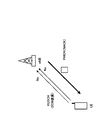
- PHICH NACK means that the same data is retransmitted from the same (previously transmitted) RB for all CWs (here 2CW) after RTD, and PHICH ACK is all CWs after RTD. It means that neither is transmitted. That is, the PHICH for all CWs is bundled (bundling).
- all CW (2CW) NDI (1 bit indicating new data transmission / retransmission)
- IR RV in LTE UL grant, included in TBS (Transport Block Scheme) information
- MCS Transmission Block Scheme
- a mode in which both codewords are demodulated in error and retransmitted HARQ control in this mode includes (1-1) a method of notifying NACK by PHICH, and (1-2) retransmitting by UL grant of PDCCH. There is a method to request.
- the method of (1-2) retransmits 2CW from the radio base station apparatus using the UL grant of PDCCH.
- the HARQ parameter is transmitted.
- the mobile terminal apparatus (UE) retransmits both CWs using PUSCH.
- This method is suitable for adaptive retransmission in which retransmission is performed using different RBs during retransmission.
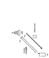
- a mode in which both codewords are correctly demodulated HARQ control in this mode includes (2-1) a method of requesting new data transmission with UL grant of PDCCH, and (2-2) notification of ACK with PHICH There is a way to do it.
- This method is suitable for adaptive retransmission in which retransmission is performed using different RBs during retransmission. If there is no error (correct) in the 2CW PUSCH signal and the new transmission data is not buffered, the method (2-2) is adopted.
- the method of (2-2) receives an ACK (both) from the radio base station apparatus by PHICH. Of CW is correct (Yes)). If the new transmission data is buffered in the mobile terminal apparatus, the mobile terminal apparatus transmits the new transmission data after receiving the UL grant including the HARQ parameter for the new data transmission from the radio base station apparatus. On the other hand, in the mobile terminal device, if new transmission data is not buffered, data transmission is not performed by not reporting by UL grant after RTD. This method is suitable for non-adaptive retransmission in which retransmission is performed using the same RB as the previously transmitted RB.
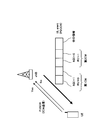
- (3) Mode in which demodulation is error and retransmission only in one codeword HARQ control in this mode includes (3-1) a method of requesting retransmission with UL grant of PDCCH, and (3-2) ACK with PHICH There are a notification method and a (3-3) NACK notification method using PHICH.
- the HARQ parameter for new data transmission and the HARQ parameter for retransmission are transmitted from the radio base station apparatus using the UL grant of PDCCH.
- new data transmission is instructed for the first CW, and retransmission is instructed for the second CW.
- This method is suitable for adaptive retransmission in which retransmission is performed using different RBs during retransmission.
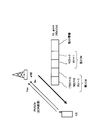
- the HARQ parameter for stopping transmission and the HARQ for retransmission are transmitted from the radio base station apparatus with UL grant of PDCCH.
- TBS 0 indicates transmission stop. Therefore, in FIG. 10, the transmission stop is instructed for the first CW, and the retransmission is instructed for the second CW.
- This method is suitable for adaptive retransmission in which retransmission is performed using different RBs during retransmission.
- the wireless base station apparatus In the method of (3-3), there is an error in the PUSCH signal of one CW (second CW) in the radio base station apparatus (eNB), and there is no error in the PUSCH signal of the other CW (first CW) (correct). At this time, regardless of whether there is an error in the PUSCH signal, the wireless base station apparatus notifies NACK (both CWs are error (No)) by PHICH, and retransmits the signals of both CWs.
- NACK both CWs are error (No)
- FIG. 11 is a diagram showing a radio communication system having mobile terminal apparatuses and radio base station apparatuses according to the embodiment of the present invention.
- the wireless communication system is a system to which, for example, E-UTRA (Evolved UTRA and UTRAN) is applied.
- the radio communication system includes a radio base station apparatus (eNB: eNodeB) 2 (2 1 , 2 2 ... 2 l , l is an integer of l> 0) and a plurality of mobile terminal apparatuses communicating with the radio base station apparatus 2 (UE) 1 n (1 1 , 1 2 , 1 3 ,... 1 n , n is an integer of n> 0).
- the radio base station device 2 is connected to an upper station, for example, an access gateway device 3, and the access gateway device 3 is connected to the core network 4.
- the mobile terminal apparatus 1 n communicates with the radio base station apparatus 2 by E-UTRA in the cell 5 (5 1 , 5 2 ).
- the present embodiment shows two cells, the present invention can be similarly applied to three or more cells. Since each mobile terminal device (1 1 , 1 2 , 1 3 ,... 1 n ) has the same configuration, function, and state, the following description will be given as the mobile terminal device 1 n unless otherwise specified. To proceed.
- OFDM Orthogonal Frequency Division Multiple Access
- SC-FDMA Single Carrier Frequency Division Multiple Access
- OFDM is a multi-carrier transmission scheme that performs communication by dividing a frequency band into a plurality of narrow frequency bands (subcarriers) and mapping data to each subcarrier.
- SC-FDMA is a single carrier transmission scheme in which frequency bands are divided for each terminal and a plurality of mobile terminal apparatuses use different frequency bands to reduce interference between mobile terminal apparatuses.
- a physical downlink shared channel shared by each mobile terminal device 1 n and a physical downlink shared channel are used.
- the physical downlink shared channel is also called a downlink L1 / L2 control channel.
- User data that is, a normal data signal is transmitted through the physical downlink shared channel.
- downlink scheduling information DL Scheduling Information
- acknowledgment information ACK / NACK
- uplink grant UL Grant
- TPC command Transmission Power Control Command
- the downlink scheduling information includes, for example, the ID of a user who performs communication using a physical downlink shared channel, information on the transport format of the user data, that is, information on data size, modulation scheme, retransmission control (HARQ), It includes downlink resource block allocation information and the like.
- the uplink scheduling grant includes, for example, the ID of a user who performs communication using the physical uplink shared channel, information on the transport format of the user data, that is, information on the data size and modulation scheme, and uplink resources. This includes block allocation information, information on uplink shared channel transmission power, and the like.
- the uplink resource block corresponds to a frequency resource and is also called a resource unit.
- the delivery confirmation information (ACK / NACK) is delivery confirmation information related to the uplink shared channel.
- the contents of the acknowledgment information are expressed by either an acknowledgment (ACK: Acknowledgement) indicating that the transmission signal has been properly received or a negative acknowledgment (NACK: Negative Acknowledgement) indicating that the transmission signal has not been properly received. Is done.
- a physical uplink shared channel (PUSCH) shared by each mobile terminal device 1 n and a physical uplink control channel (PUCCH) are used.
- User data that is, a normal data signal is transmitted through the physical uplink shared channel.
- downlink channel quality information CQI: Channel Quality Indicator
- AMC adaptive modulation and coding scheme
- acknowledgment information of the physical downlink shared channel are transmitted.
- the resource allocation of the uplink shared channel means that the radio base station apparatus may perform communication using the uplink shared channel in the subsequent subframe using the physical downlink control channel of a certain subframe. Means to notify the mobile terminal device.
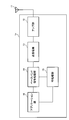
- FIG. 12 is a block diagram showing a schematic configuration of the mobile terminal apparatus according to the embodiment of the present invention.
- the mobile terminal device 1 n shown in FIG. 12 mainly includes an antenna 11, an amplifier unit 12, a transmission / reception unit 13, a baseband signal processing unit 14, a call processing unit 15, and an application unit 16. .
- the radio frequency signal received by the antenna 11 is corrected by the amplifier unit 12 and the received power is corrected to a constant power under AGC (Auto Gain Control). So that it is amplified.
- the amplified radio frequency signal is frequency-converted into a baseband signal in the transmission / reception unit 13.
- the baseband signal is subjected to predetermined processing (error correction, decoding, etc.) by the baseband signal processing unit 14 and then sent to the call processing unit 15 and the application unit 16.
- the call processing unit 15 manages communication with the radio base station apparatus 2, and the application unit 16 performs processing related to a layer higher than the physical layer and the MAC layer.
- the mobile terminal apparatus 1 n of the present invention receives downlink signals including reference signals from at least a plurality of radio base station apparatuses related to downlink CoMP.
- the uplink signal is input from the application unit 16 to the baseband signal processing unit 14.
- the baseband signal processing unit 14 retransmission control processing, scheduling, transmission format selection, channel coding, and the like are performed and transferred to the transmission / reception unit 13.
- the transmission / reception unit 13 frequency-converts the baseband signal output from the baseband signal processing unit 14 into a radio frequency signal.
- the frequency-converted signal is then amplified by the amplifier unit 12 and transmitted from the antenna 11.
- feedback information including a channel quality measurement result is transmitted to each of a plurality of radio base station devices.
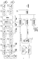
- FIG. 13 is a block diagram showing a configuration of a processing unit including a baseband signal processing unit in the mobile terminal apparatus shown in FIG.
- the mobile terminal apparatus shown in FIG. 13 includes a transmission unit and a reception unit.
- the transmission unit includes data encoding units 1301 and 1302, data modulation units 1303 and 1304, DFT units 1305 and 1306, subcarrier mapping units 1307 and 1308, codeword / layer mapping unit 1309, and precoding weight multiplication.
- the reception unit includes an OFDM demodulation unit 1314, a downlink PDCCH signal decoding unit 1315, a downlink PHICH signal decoding unit 1316, and a downlink PDSCH signal decoding unit 1317.
- the mobile terminal apparatus also includes a new data transmission / retransmission determination unit 1318, a retransmission data buffer 1319 for storing retransmission data, and a new transmission data buffer 1320 for storing new transmission data.
- a new data transmission / retransmission determination unit 1318 for storing retransmission data
- a new transmission data buffer 1320 for storing new transmission data.
- the receiving unit receives a downlink signal including a PDCCH signal, a PHICH signal, and a PDSCH signal.
- the OFDM demodulator 1314 performs predetermined OFDM demodulation processing on the received signal.
- OFDM demodulation section 1314 outputs the demodulated signal to downlink PDCCH signal decoding section 1315, downlink PHICH signal decoding section 1316, and downlink PDSCH signal decoding section 1317.
- the downlink PDCCH signal decoding unit 1315 decodes the demodulated downlink PDCCH signal (downlink L1 / L2 control signal). Also, downlink PDCCH signal decoding section 1315 converts the demodulated downlink PDCCH signal into data encoding sections 1301 and 1302, data modulation sections 1303 and 1304, subcarrier mapping sections 1307 and 1308, codeword / layer mapping section 1309, precoding. The data is output to weight multiplication section 1310 and new data transmission / retransmission determination section 1318.
- RI rank number information
- MCS information is output to data encoding sections 1301, 1302 and data modulation sections 1303, 1304, and scheduling information (resource allocation information) is sub It is output to carrier mapping sections 1307 and 1308, and precoding information (PMI) is output to precoding weight multiplication section 1310.
- PMI precoding information
- the downlink PHICH signal decoding unit 1316 decodes the demodulated downlink PHICH signal. Thereby, a PHICH signal (ACK or NACK) is obtained. Further, downlink PHICH signal decoding section 1316 outputs the demodulated downlink PHICH signal to new data transmission / retransmission determination section 1318. Downlink PDSCH signal decoding section 1317 decodes the demodulated downlink data signal.
- the new data transmission / retransmission determination unit 1318 determines whether the PHICH signal is ACK or NACK. In addition, when the PHICH signal is NACK, new data transmission / retransmission determination section 1318 transmits an instruction to retransmit all CWs (here, two CWs) (transmits a retransmission signal to the radio base station apparatus). Instructions). Accordingly, the mobile terminal apparatus retransmits both CW retransmission signals stored in the retransmission data buffer 1319 using PUSCH. This control is performed in a mode (1-1) in which both code words are demodulated in error and retransmitted, or in a mode (3-3) in which demodulating is errored and retransmitted for only one codeword.
- the new data transmission / retransmission determination unit 1318 includes a UL grant including a HARQ parameter for new data transmission if new transmission data is buffered in the new transmission data buffer 1320. Is received from the radio base station apparatus, an instruction to transmit new transmission data is issued. On the other hand, if new transmission data is not buffered in new transmission data buffer 1320, data transmission is not performed after RTD. This control is performed in a mode (2-2) in which both codewords are correctly demodulated, or in a mode (3-2) in which demodulation is erroneous and retransmission is performed for only one codeword.
- the new data transmission / retransmission determination unit 1318 instructs new data transmission and / or retransmission based on the UL grant information of the PDCCH.
- the downlink PDCCH signal includes a UL grant to retransmit to one CW
- an instruction to retransmit one CW (instruction to transmit a retransmission signal to the radio base station apparatus) is issued.
- both codewords are demodulated in error and retransmitted (1-2), both codewords are demodulated correctly (2-1), only one codeword is demodulated in error, and retransmitted. Performed in the mode (3-1) of performing.
- Data encoders 1301 and 1302 perform error correction encoding on the data signal using the channel coding rate corresponding to the MCS information.
- Data encoding sections 1301 and 1302 output data signals subjected to error correction encoding to data modulation sections 1303 and 1304.
- Data modulation sections 1303 and 1304 perform data modulation on the data signal that has been data-encoded in a data modulation scheme corresponding to the MCS information.
- Data modulation sections 1303 and 1304 output data signals after data modulation to DFT (Discrete Fourier Transform) sections 1305 and 1306.
- the DFT units 1305 and 1306 convert time domain data signals into frequency domain signals.
- DFT sections 1305 and 1306 output the data signal after DFT to subcarrier mapping sections 1307 and 1308.
- the subcarrier mapping units 1307 and 1308 map the data signal after DFT to subcarriers based on the scheduling information.
- the subcarrier mapping units 1307 and 1308 output the subcarrier mapped data signal to the codeword / layer mapping unit 1309.
- the codeword / layer mapping unit 1309 maps a codeword to a layer based on the rank number information.
- the codeword / layer mapping section 1309 outputs the mapped signal to the precoding weight multiplication section 1310.
- the precoding weight multiplication unit 1310 multiplies the signal mapped to the layer based on the precoding information by the precoding weight.
- Precoding weight multiplication section 1310 outputs the precoded signal to multiplexing section 1311.
- the multiplexing unit 1311 multiplexes another signal such as a reference signal with the data signal after precoding.
- the multiplexing unit 1311 outputs the signal after multiplexing the reference signal and the like to IFFT (Inverse Fast Fourier Transform) units 1312a and 1312b.
- IFFT sections 1312a and 1312b perform IFFT on the multiplexed signals and convert them into time domain signals.
- IFFT sections 1312a and 1312b output signals after IFFT to CP assignment sections 1313a and 1313b.
- CP assigning sections 1313a and 1313b assign CP to the signal after IFFT.
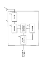
- FIG. 14 is a block diagram showing a schematic configuration of the radio base station apparatus according to the embodiment of the present invention.
- the radio base station apparatus 2 n shown in FIG. 14 mainly includes an antenna 21, an amplifier unit 22, a transmission / reception unit 23, a baseband signal processing unit 24, a call processing unit 25, and a transmission path interface 26. ing.
- the radio frequency signal received by the antenna 21 is amplified by the amplifier unit 22 so that the received power is corrected to a constant power under the AGC. Is done.
- the amplified radio frequency signal is frequency-converted into a baseband signal by the transmission / reception unit 23.
- the baseband signal is subjected to predetermined processing (error correction, decoding, etc.) by the baseband signal processing unit 24 and then transferred to the access gateway device via the transmission path interface 26.
- the access gateway device 3 is connected to the core network 4 and manages each mobile terminal device.
- the received SINR and interference level of the radio frequency signal received by the radio base station device 2n are measured based on the uplink baseband signal.
- the call processing unit 25 transmits / receives call processing control signals to / from the radio control station of the host device, and manages the state of the radio base station device 2n and allocates resources.
- the downlink signal is input from the host device to the baseband signal processing unit 24 via the transmission path interface 26.
- the baseband signal processing unit 24 retransmission control processing, scheduling, transmission format selection, channel coding, and the like are performed and transferred to the transmission / reception unit 23.
- the transmission / reception unit 23 converts the frequency of the baseband signal output from the baseband signal processing unit 24 into a radio frequency signal.
- the frequency-converted signal is then amplified by the amplifier unit 22 and transmitted from the antenna 21.
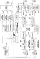
- FIG. 15 is a block diagram showing a configuration of a processing unit including a baseband signal processing unit in the radio base station apparatus shown in FIG.
- the radio base station apparatus shown in FIG. 15 includes a transmission unit and a reception unit.
- the transmission unit includes a PHICH signal generation unit 1501, an individual user data generation unit 1502, a PDSCH signal generation unit 1503, a PDCCH signal generation unit 1504, and an OFDM modulation unit 1505.
- the transmission unit transmits a downlink signal including a PHICH signal, a PDSCH signal, and a PDCCH signal to the mobile terminal apparatus.
- the reception unit includes CP removal units 1506 and 1508, symbol synchronization units 1507 and 1509, FFT (Fast Fourier Transform) units 1510 and 1511, subcarrier demapping units 1512 and 1513, frequency domain equalization unit 1514, A channel estimation unit 1515, IDFT (Inverse Discrete Fourier Transform) units 1516 and 1517, data demodulation units 1518 and 1519, and data decoding units 1520 and 1521 are provided.
- the radio base station apparatus includes a retransmission information channel selection unit 1522, a scheduler 1523, a precoding weight / rank number selection unit 1524, an MCS selection unit 1525, and a channel quality measurement unit 1526.
- the receiving unit receives signals from a plurality of CWs (here, two CWs) from the mobile terminal apparatus.
- the PHICH signal generation unit 1501 generates a PHICH signal (ACK / NACK). This PHICH signal is determined by whether or not there is an error in the PUSCH signal (reproduced CW # 1 transmission data, reproduced CW # 2 transmission data). The PHICH signal generation unit 1501 generates 1-bit PHICH (NACK) when there is an error in all CWs. Also, the PHICH signal generation unit 1501 generates 1-bit PHICH (ACK) when there is no error in all CWs. The PHICH signal generation unit 1501 outputs the PHICH signal to the OFDM modulation unit 1505.
- the individual user data generation unit 1502 generates downlink individual user data and outputs it to the PDSCH signal generation unit 1503.
- the PDSCH signal generation unit 1503 generates downlink dedicated user data and a higher layer control signal (RRC signaling) as a PDSCH signal.
- RRC signaling higher layer control signal
- PDSCH signal generation section 1503 outputs the PDSCH signal to OFDM modulation section 1505.
- the PDCCH signal generation unit 1504 generates a PDCCH signal including an uplink grant (UL grant).
- UL grant includes resource allocation information, PMI, RI (Rank Indicator), MCS, and HARQ parameters (NDI, RV, MCS).
- PMI resource allocation information
- RI Rank Indicator
- MCS Mobility Control Function
- NDI NDI, RV, MCS
- PDCCH signal generation section 1504 outputs the PDCCH signal to OFDM modulation section 1505.
- the OFDM modulation unit 1505 performs predetermined OFDM modulation processing on the PHICH signal, the PDSCH signal, and the PDCCH signal to generate a transmission signal.
- CP removing sections 1506 and 1508 remove the CP from the received signal for each antenna and extract an effective signal portion.
- CP removing sections 1506 and 1508 output received signals after CP removal to FFT sections 1510 and 1511, respectively.
- Symbol synchronization sections 1507 and 1509 perform symbol synchronization of the received signals and output symbol synchronization information to CP removal sections 1506 and 1508.
- CP removing sections 1506 and 1508 remove the CP from the received signal based on the symbol synchronization information.
- FFT sections 1510 and 1511 perform FFT on the received signal after CP removal and convert it to a frequency domain signal.
- FFT sections 1510 and 1511 output the signals after FFT to subcarrier demapping sections 1512 and 1513, respectively.
- Subcarrier demapping sections 1512 and 1513 extract data signals from frequency domain signals using resource mapping information for the signals after FFT.
- Subcarrier demapping sections 1512 and 1513 output signals after subcarrier demapping to channel estimation section 1515 and frequency domain equalization section 1514, respectively.
- the channel estimation unit 1515 performs channel estimation using a signal (reference signal) after subcarrier demapping.
- Channel estimation unit 1515 outputs the obtained channel estimation value to frequency domain equalization unit 1514.
- the frequency domain equalization unit 1514 compensates the channel fluctuation estimated by the channel estimation unit 1515 for the data signal after the subcarrier demapping.
- the frequency domain equalization unit 1514 outputs the equalized data signals to the IDFT units 1516 and 1517, respectively.
- the IDFT units 1516 and 1517 convert frequency domain signals into time domain signals. IDFT sections 1516 and 1517 output the signals after IDFT to data demodulation sections 1518 and 1519, respectively.
- Data demodulating sections 1518 and 1519 demodulate the signal after IDFT in a data modulation scheme corresponding to the transmission format (coding rate / demodulation scheme).
- Data demodulation sections 1518 and 1519 output the signals after data demodulation to data decoding sections 1520 and 1521, respectively.
- Data decoding sections 1520 and 1521 decode the data signal after data demodulation and output it as transmission data (reproduced transmission data of CW # 1 and reproduced transmission data of CW # 2).
- the channel quality measurement unit 1526 measures quality information using the reference signal transmitted from the mobile terminal apparatus.
- the measured quality information is output to the scheduler 1523, the precoding weight / rank number selection unit 1524, and the MCS selection unit 1525.
- the scheduler 1523 scheduling is performed based on the quality information.
- the scheduler 1523 outputs the resource allocation information to the individual user data generation unit 1502 and the PDCCH signal generation unit 1504.
- the precoding weight / rank number selection unit 1524 performs PMI generation and rank selection based on the quality information.
- Precoding weight / rank number selection section 1524 outputs PMI and RI to PDCCH signal generation section 1504.
- the MCS selection unit 1525 performs MCS selection based on the quality information.
- the MCS selection unit 1525 outputs the MCS to the PDCCH signal generation unit 1504.
- the retransmission information channel selection unit 1522 selects whether to notify retransmission by PHICH or to notify retransmission by UL grant according to the error state of the transmission data of each CW.
- the retransmission information channel selection unit 1522 performs demodulation in both codewords in the case of an error in demodulation and retransmission (1-1), or in the case of an error in demodulation and retransmission for only one codeword (3-3).
- PHICH (NACK) is selected to notify retransmission.
- the retransmission information channel selection unit 1522 has a mode (2-2) in which both codewords are correctly demodulated or a mode in which demodulation is erroneous and retransmission is performed on only one codeword (3-2).
- PHICH is selected to notify retransmission by PHICH (ACK).
- ACK PHICH
- retransmission information channel selection section 1522 has a mode in which both code words are demodulated in error and performs retransmission (1-2), a mode in which both code words are correctly demodulated (2-1), and only one of the code words
- the PDCCH is selected in order to notify the retransmission with the UL grant of the PDCCH.
- the radio base station apparatus receives a plurality of CW signals and receives a 1-bit NACK.
- PHICH signal is generated, and this NACK PHICH signal is transmitted to the mobile terminal apparatus.
- retransmission signals for all CWs are transmitted to the radio base station apparatus according to the NACK PHICH.
- the radio base station apparatus when both CWs are correctly demodulated in the radio base station apparatus, the radio base station apparatus generates a 1-bit ACK PHICH signal and transmits the ACK PHICH signal to the mobile terminal.
- the mobile terminal device transmits new transmission data to the radio base station device based on the ACK PHICH signal.
- the PDCCH signal including a UL grant indicating that retransmission is performed for one CW in the radio base station apparatus.
- the PDCCH signal is transmitted to the mobile terminal apparatus, and the mobile terminal apparatus transmits one CW retransmission signal to the radio base station apparatus based on UL grant.
- the present invention is not limited to the above embodiment, and can be implemented with various modifications.
- the number of ranks and the number of transmitting antennas are examples, and are not limited to this.
- the number of processing units and the processing procedure in the above description can be changed as appropriate without departing from the scope of the present invention.
- Each element shown in the figure represents a function, and each functional block may be realized by hardware or software. Other modifications can be made without departing from the scope of the present invention.
- the present invention is useful for an LTE-A system mobile terminal apparatus, radio base station apparatus, and radio communication method.
Landscapes
- Engineering & Computer Science (AREA)
- Computer Networks & Wireless Communication (AREA)
- Signal Processing (AREA)
- Mobile Radio Communication Systems (AREA)
- Detection And Prevention Of Errors In Transmission (AREA)
- Communication Control (AREA)
Abstract
Description
LTEシステムにおいては、上りリンクでMIMO多重伝送が規定されていない。このため、PUSCH信号は、図2に示すように、移動端末装置(UE:User Equipment)から無線基地局装置(eNB)に対して1コードワード(CW)で送信される。また、このとき、HARQ制御としては、物理HARQ指標チャネル(PHICH)で肯定応答(ACK)(RTD後はデータの送信を行わない)又は否定応答(NACK)(RTD後に同一のRBから同じデータを再送)が1ビットで送られると共に、PDCCHのアップリンクグラント(UL grant)でHARQパラメータが送られる。ここで、HARQパラメータとしては、新規送信データ指標(NDI:New Data Indicator )、Incremental Redundancy (IR)におけるRedundancy Version (RV)、MCSなどが挙げられる。なお、LTEシステムにおいては、RVはTBS(Transport Block Scheme)情報に含まれる。また、UL grantとPHICHが同時に送られている場合には、UL grantの情報を優先する。
この態様におけるHARQ制御としては、(1-1)PHICHでNACKを通知する方法と、(1-2)PDCCHのUL grantで再送を要求する方法とがある。
この態様におけるHARQ制御としては、(2-1)PDCCHのUL grantで新規データ送信を要求する方法と、(2-2)PHICHでACKを通知する方法とがある。
この態様におけるHARQ制御としては、(3-1)PDCCHのUL grantで再送を要求する方法と、(3-2)PHICHでACKを通知する方法と、(3-3)PHICHでNACKを通知する方法とがある。
下りリンクについては、各移動端末装置1nで共有される物理下り共有チャネル(PDSCH:Physical Downlink Shared Channel)と、物理下り共有チャネルとが用いられる。物理下り共有チャネルは下りL1/L2制御チャネルとも呼ばれる。上記物理下り共有チャネルにより、ユーザデータ、すなわち、通常のデータ信号が伝送される。また、物理下り制御チャネルにより、下りスケジューリング情報(DL Scheduling Information)、送達確認情報(ACK/NACK)、アップリンクグラント(UL Grant)、TPCコマンド(Transmission Power Control Command)などが伝送される。下りスケジューリング情報には、例えば、物理下り共有チャネルを用いて通信を行うユーザのIDや、そのユーザデータのトランスポートフォーマットの情報、すなわち、データサイズ、変調方式、再送制御(HARQ)に関する情報や、下りリンクのリソースブロックの割り当て情報などが含まれる。
Claims (9)
- 物理HARQ指標チャネル信号を受信する受信手段と、前記物理HARQ指標チャネル信号が肯定応答であるか否定応答であるかを判定する判定手段と、前記物理HARQ指標チャネル信号が否定応答である場合に、全コードワードについて再送信号を無線基地局装置に送信する送信手段と、を具備することを特徴とする移動端末装置。
- 前記物理HARQ指標チャネル信号が肯定応答である場合に、新規送信データ及び再送信号を無線基地局装置に送信しないことを特徴とする請求項1記載の移動端末装置。
- 前記受信手段は下り制御チャネル信号を受信し、前記下り制御チャネル信号に一つのコードワードに対して再送する旨のアップリンクグラントが含まれている場合に、前記一つのコードワードの再送信号を無線基地局装置に送信することを特徴とする請求項1記載の移動端末装置。
- 複数のコードワードの信号を受信する受信手段と、全コードワードに誤りがあったときに1ビットの否定応答の物理HARQ指標チャネル信号を生成する物理HARQ指標チャネル信号生成手段と、前記物理HARQ指標チャネル信号を送信する送信手段と、を具備することを特徴とする無線基地局装置。
- 前記物理HARQ指標チャネル信号生成手段は、全コードワードに誤りがなかったときに1ビットの肯定応答の物理HARQ指標チャネル信号を生成し、前記送信手段は、前記物理HARQ指標チャネル信号を移動端末装置に送信することを特徴とする請求項4記載の無線基地局装置。
- 一つのコードワードに誤りがあったときに、前記一つのコードワードに対して再送する旨のアップリンクグラントを含む下り制御チャネル信号を生成する下り制御チャネル信号生成手段を具備し、前記送信手段は前記下り制御チャネル信号を移動端末装置に送信することを特徴とする請求項4記載の無線基地局装置。
- 無線基地局装置において、複数のコードワードの信号を受信する工程と、全コードワードに誤りがあったときに1ビットの否定応答の物理HARQ指標チャネル信号を生成する工程と、前記否定応答の物理HARQ指標チャネル信号を送信する工程と、前記移動端末装置において、前記否定応答の物理HARQ指標チャネル信号を受信する工程と、前記否定応答の物理HARQ指標チャネル信号に基づいて、全コードワードについて再送信号を前記無線基地局装置に送信する工程と、を具備することを特徴とする無線通信方法。
- 前記無線基地局装置において、全コードワードに誤りがなかったときに1ビットの肯定応答の物理HARQ指標チャネル信号を生成する工程と、前記肯定応答の物理HARQ指標チャネル信号を前記移動端末装置に送信する工程と、前記移動端末装置において、前記肯定応答の物理HARQ指標チャネル信号を受信する工程と、前記肯定応答の物理HARQ指標チャネル信号に基づいて、新規送信データ及び再送信号を前記無線基地局装置に送信しない工程と、を具備することを特徴とする請求項7記載の無線通信方法。
- 前記無線基地局装置において、一つのコードワードに誤りがあったときに、前記一つのコードワードに対して再送する旨のアップリンクグラントを含む下り制御チャネル信号を生成する工程と、前記下り制御チャネル信号を前記移動端末装置に送信する工程と、前記移動端末装置において、前記下り制御チャネル信号を受信する工程と、前記アップリンクグラントに基づいて、前記一つのコードワードの再送信号を前記無線基地局装置に送信する工程と、を具備することを特徴とする請求項7記載の無線通信方法。
Priority Applications (2)
| Application Number | Priority Date | Filing Date | Title |
|---|---|---|---|
| CN2011800102832A CN102783206A (zh) | 2010-02-19 | 2011-02-09 | 移动终端装置、无线基站装置以及无线通信方法 |
| US13/579,104 US8767664B2 (en) | 2010-02-19 | 2011-02-09 | Mobile terminal apparatus, radio base station apparatus and radio communication method |
Applications Claiming Priority (2)
| Application Number | Priority Date | Filing Date | Title |
|---|---|---|---|
| JP2010-034551 | 2010-02-19 | ||
| JP2010034551A JP5073770B2 (ja) | 2010-02-19 | 2010-02-19 | 移動端末装置、無線基地局装置及び無線通信方法 |
Publications (1)
| Publication Number | Publication Date |
|---|---|
| WO2011102267A1 true WO2011102267A1 (ja) | 2011-08-25 |
Family
ID=44482854
Family Applications (1)
| Application Number | Title | Priority Date | Filing Date |
|---|---|---|---|
| PCT/JP2011/052697 Ceased WO2011102267A1 (ja) | 2010-02-19 | 2011-02-09 | 移動端末装置、無線基地局装置及び無線通信方法 |
Country Status (4)
| Country | Link |
|---|---|
| US (1) | US8767664B2 (ja) |
| JP (1) | JP5073770B2 (ja) |
| CN (1) | CN102783206A (ja) |
| WO (1) | WO2011102267A1 (ja) |
Cited By (1)
| Publication number | Priority date | Publication date | Assignee | Title |
|---|---|---|---|---|
| WO2021166936A1 (ja) * | 2020-02-18 | 2021-08-26 | シャープ株式会社 | ステーション装置、通信方法 |
Families Citing this family (24)
| Publication number | Priority date | Publication date | Assignee | Title |
|---|---|---|---|---|
| KR101785656B1 (ko) * | 2010-03-04 | 2017-10-16 | 엘지전자 주식회사 | Ack/nack 신호를 전송하는 방법 및 이를 위한 장치 |
| JP5685307B2 (ja) | 2010-03-29 | 2015-03-18 | エルジー エレクトロニクス インコーポレイティド | アップリンク多重アンテナ伝送を支援するための効率的な制御情報伝送方法及び装置 |
| US9246640B2 (en) * | 2010-04-05 | 2016-01-26 | Qualcomm Incorporated | Acknowledgement bundling in a MIMO communication system |
| US9585083B2 (en) * | 2011-06-17 | 2017-02-28 | Samsung Electronics Co., Ltd. | Apparatus and method for supporting network entry in a millimeter-wave mobile broadband communication system |
| CN103733677B (zh) * | 2011-08-12 | 2017-07-14 | 松下电器(美国)知识产权公司 | 通信装置及重发控制方法 |
| US10375725B2 (en) | 2015-03-16 | 2019-08-06 | Lg Electronics Inc. | Method of fast-retransmitting uplink data in wireless communication system and apparatus therefor |
| US10482004B2 (en) * | 2015-10-16 | 2019-11-19 | Successfactors, Inc. | Test data framework |
| US10784901B2 (en) | 2015-11-12 | 2020-09-22 | Qualcomm Incorporated | Puncturing for structured low density parity check (LDPC) codes |
| EP3391553A1 (en) * | 2015-12-14 | 2018-10-24 | Nokia Solutions and Networks Oy | Data retransmission |
| WO2017135721A1 (ko) * | 2016-02-04 | 2017-08-10 | 한국전자통신연구원 | 통신 네트워크에서 상향링크 전송의 스케쥴링 방법 |
| EP3413494B1 (en) * | 2016-02-04 | 2022-09-28 | Electronics and Telecommunications Research Institute | Method for communicating in network supporting licensed and unlicensed bands |
| KR102820057B1 (ko) | 2016-02-04 | 2025-06-12 | 한국전자통신연구원 | 통신 네트워크에서 상향링크 전송의 스케쥴링 방법 |
| US11043966B2 (en) | 2016-05-11 | 2021-06-22 | Qualcomm Incorporated | Methods and apparatus for efficiently generating multiple lifted low-density parity-check (LDPC) codes |
| US10454499B2 (en) | 2016-05-12 | 2019-10-22 | Qualcomm Incorporated | Enhanced puncturing and low-density parity-check (LDPC) code structure |
| US9917675B2 (en) | 2016-06-01 | 2018-03-13 | Qualcomm Incorporated | Enhanced polar code constructions by strategic placement of CRC bits |
| US10313057B2 (en) | 2016-06-01 | 2019-06-04 | Qualcomm Incorporated | Error detection in wireless communications using sectional redundancy check information |
| US10469104B2 (en) | 2016-06-14 | 2019-11-05 | Qualcomm Incorporated | Methods and apparatus for compactly describing lifted low-density parity-check (LDPC) codes |
| EP3491758B1 (en) | 2016-07-27 | 2023-06-28 | QUALCOMM Incorporated | Design of hybrid automatic repeat request (harq) feedback bits for polar codes |
| US10312939B2 (en) | 2017-06-10 | 2019-06-04 | Qualcomm Incorporated | Communication techniques involving pairwise orthogonality of adjacent rows in LPDC code |
| EP3641180B1 (en) * | 2017-06-15 | 2022-05-11 | Fujitsu Limited | Base station device, terminal device, wireless communication system, and communication method |
| US12476733B2 (en) | 2017-06-19 | 2025-11-18 | Qualcomm Incorporated | Communication techniques with self-decodable redundancy versions (RVs) using systematic codes |
| CN110832799B (zh) | 2017-07-07 | 2021-04-02 | 高通股份有限公司 | 应用低密度奇偶校验码基图选择的通信技术 |
| KR102501635B1 (ko) * | 2018-09-27 | 2023-02-21 | 후지쯔 가부시끼가이샤 | 기지국 장치, 단말 장치 및 무선 통신 시스템 |
| JP7667055B2 (ja) * | 2021-09-30 | 2025-04-22 | トヨタ自動車株式会社 | 送信制御方法、及び情報処理装置 |
Citations (1)
| Publication number | Priority date | Publication date | Assignee | Title |
|---|---|---|---|---|
| WO2009066406A1 (ja) * | 2007-11-22 | 2009-05-28 | Panasonic Corporation | 無線通信装置、無線通信システム及び無線通信方法 |
Family Cites Families (6)
| Publication number | Priority date | Publication date | Assignee | Title |
|---|---|---|---|---|
| KR100464325B1 (ko) * | 2001-10-15 | 2005-01-03 | 삼성전자주식회사 | 이동통신시스템에서 패킷 재전송을 위한 송수신 장치 및 방법 |
| WO2006071049A1 (en) * | 2004-12-27 | 2006-07-06 | Lg Electronics Inc. | Supporting hybrid automatic retransmission request in orthogonal frequency division multiplexing access radio access system |
| KR101084127B1 (ko) * | 2004-12-27 | 2011-11-17 | 엘지전자 주식회사 | Ofdma 무선 접속 시스템에서의 자동 재전송 요구지원 방법 |
| KR101381095B1 (ko) * | 2007-04-26 | 2014-04-02 | 삼성전자주식회사 | 무선통신 시스템에서 응답 신호 송수신 방법 및 장치 |
| WO2010005951A2 (en) * | 2008-07-07 | 2010-01-14 | Interdigital Patent Holdings, Inc. | Method and apparatus for cooperative relaying in wireless communications |
| CN101527623B (zh) * | 2009-04-08 | 2014-06-11 | 中兴通讯股份有限公司 | 物理混合自动请求重传指示信道中信息的传输方法和系统 |
-
2010
- 2010-02-19 JP JP2010034551A patent/JP5073770B2/ja not_active Expired - Fee Related
-
2011
- 2011-02-09 CN CN2011800102832A patent/CN102783206A/zh active Pending
- 2011-02-09 WO PCT/JP2011/052697 patent/WO2011102267A1/ja not_active Ceased
- 2011-02-09 US US13/579,104 patent/US8767664B2/en not_active Expired - Fee Related
Patent Citations (1)
| Publication number | Priority date | Publication date | Assignee | Title |
|---|---|---|---|---|
| WO2009066406A1 (ja) * | 2007-11-22 | 2009-05-28 | Panasonic Corporation | 無線通信装置、無線通信システム及び無線通信方法 |
Non-Patent Citations (1)
| Title |
|---|
| "3rd Generation Partnership Project;Technical Specification Group Radio Access Network; Further Advancements for E-UTRA Physical Layer Aspects(Release 9)", 3GPP TR 36.814 V1.6.0, January 2010 (2010-01-01), pages 7 - 11 * |
Cited By (1)
| Publication number | Priority date | Publication date | Assignee | Title |
|---|---|---|---|---|
| WO2021166936A1 (ja) * | 2020-02-18 | 2021-08-26 | シャープ株式会社 | ステーション装置、通信方法 |
Also Published As
| Publication number | Publication date |
|---|---|
| CN102783206A (zh) | 2012-11-14 |
| JP2011172053A (ja) | 2011-09-01 |
| US20130033979A1 (en) | 2013-02-07 |
| US8767664B2 (en) | 2014-07-01 |
| JP5073770B2 (ja) | 2012-11-14 |
Similar Documents
| Publication | Publication Date | Title |
|---|---|---|
| JP5073770B2 (ja) | 移動端末装置、無線基地局装置及び無線通信方法 | |
| US11184918B1 (en) | Method and apparatus for transport block generation with UL spatial multiplexing in a wireless communication system | |
| US9287942B2 (en) | Method and apparatus for uplink multiple input multiple output (MIMO) transmission | |
| CN102301800B (zh) | 控制发送功率的方法及其装置 | |
| US8755332B2 (en) | Radio communication control method, base station apparatus and mobile terminal apparatus | |
| US10321441B2 (en) | User terminal and radio communication method | |
| US9055571B2 (en) | Wireless communication system, communication device and communication method | |
| US10568075B2 (en) | Uplink control information sending method and receiving method, and related apparatus | |
| US8902845B2 (en) | Communication control method, base station apparatus and mobile station apparatus | |
| JP2020501456A (ja) | 物理アップリンクデータチャンネルで制御情報多重化 | |
| US20150312866A1 (en) | User terminal, radio communication system and radio communication method | |
| WO2013094578A1 (ja) | 移動通信システム、基地局装置、移動局装置、通信方法および集積回路 | |
| CN103229541A (zh) | Lte-a的物理上行链路控制信道上的上行链路控制信息复用 | |
| CN103918214A (zh) | 无线通信网络中的确认信令 | |
| WO2017187810A1 (ja) | 端末装置、基地局装置、通信方法、および、集積回路 | |
| CN110402559A (zh) | 在无线通信系统中支持多个发送时间间隔、多个子载波间隔或多个处理时间间隔的方法及其设备 | |
| WO2017187697A1 (ja) | 端末装置、基地局装置、通信方法、および、集積回路 | |
| CN110710147B (zh) | 用于pucch格式适配的用户设备、基站及通信方法 | |
| JP5053067B2 (ja) | 移動通信システム、基地局装置、ユーザ装置及び方法 | |
| JP5469776B2 (ja) | 無線通信システム、基地局装置、移動局装置、無線通信方法および集積回路 | |
| US20140198731A1 (en) | Devices for sending and receiving feedback information | |
| CN104488310A (zh) | 无线通信系统、无线基站装置以及重发控制方法 | |
| WO2011155344A1 (ja) | 無線通信システム、基地局装置、移動局装置、無線通信方法および集積回路 | |
| JP2013098952A (ja) | 移動通信システム、基地局装置、移動局装置および通信方法 | |
| WO2018084183A1 (ja) | 端末装置、基地局装置、および、通信方法 |
Legal Events
| Date | Code | Title | Description |
|---|---|---|---|
| WWE | Wipo information: entry into national phase |
Ref document number: 201180010283.2 Country of ref document: CN |
|
| 121 | Ep: the epo has been informed by wipo that ep was designated in this application |
Ref document number: 11744554 Country of ref document: EP Kind code of ref document: A1 |
|
| NENP | Non-entry into the national phase |
Ref country code: DE |
|
| WWE | Wipo information: entry into national phase |
Ref document number: 13579104 Country of ref document: US |
|
| 122 | Ep: pct application non-entry in european phase |
Ref document number: 11744554 Country of ref document: EP Kind code of ref document: A1 |