WO2011102173A1 - 水素吸蔵材 - Google Patents
水素吸蔵材 Download PDFInfo
- Publication number
- WO2011102173A1 WO2011102173A1 PCT/JP2011/050857 JP2011050857W WO2011102173A1 WO 2011102173 A1 WO2011102173 A1 WO 2011102173A1 JP 2011050857 W JP2011050857 W JP 2011050857W WO 2011102173 A1 WO2011102173 A1 WO 2011102173A1
- Authority
- WO
- WIPO (PCT)
- Prior art keywords
- hydrogen storage
- storage material
- porous
- hydrogen
- mil
- Prior art date
- Legal status (The legal status is an assumption and is not a legal conclusion. Google has not performed a legal analysis and makes no representation as to the accuracy of the status listed.)
- Ceased
Links
Images

Classifications
-
- C—CHEMISTRY; METALLURGY
- C01—INORGANIC CHEMISTRY
- C01B—NON-METALLIC ELEMENTS; COMPOUNDS THEREOF; METALLOIDS OR COMPOUNDS THEREOF NOT COVERED BY SUBCLASS C01C
- C01B3/00—Hydrogen; Gaseous mixtures containing hydrogen; Separation of hydrogen from mixtures containing it; Purification of hydrogen; Reversible storage of hydrogen
- C01B3/0005—Reversible storage of hydrogen, e.g. by hydrogen getters or electrodes
- C01B3/001—Reversible storage of hydrogen, e.g. by hydrogen getters or electrodes characterised by the uptaking media; Treatment thereof
- C01B3/0015—Organic compounds, e.g. liquid organic hydrogen carriers [LOHC] or metalorganic compounds; Solutions thereof
-
- B—PERFORMING OPERATIONS; TRANSPORTING
- B01—PHYSICAL OR CHEMICAL PROCESSES OR APPARATUS IN GENERAL
- B01J—CHEMICAL OR PHYSICAL PROCESSES, e.g. CATALYSIS OR COLLOID CHEMISTRY; THEIR RELEVANT APPARATUS
- B01J20/00—Solid sorbent compositions or filter aid compositions; Sorbents for chromatography; Processes for preparing, regenerating or reactivating thereof
- B01J20/02—Solid sorbent compositions or filter aid compositions; Sorbents for chromatography; Processes for preparing, regenerating or reactivating thereof comprising inorganic material
- B01J20/04—Solid sorbent compositions or filter aid compositions; Sorbents for chromatography; Processes for preparing, regenerating or reactivating thereof comprising inorganic material comprising compounds of alkali metals, alkaline earth metals or magnesium
-
- B—PERFORMING OPERATIONS; TRANSPORTING
- B01—PHYSICAL OR CHEMICAL PROCESSES OR APPARATUS IN GENERAL
- B01J—CHEMICAL OR PHYSICAL PROCESSES, e.g. CATALYSIS OR COLLOID CHEMISTRY; THEIR RELEVANT APPARATUS
- B01J20/00—Solid sorbent compositions or filter aid compositions; Sorbents for chromatography; Processes for preparing, regenerating or reactivating thereof
- B01J20/22—Solid sorbent compositions or filter aid compositions; Sorbents for chromatography; Processes for preparing, regenerating or reactivating thereof comprising organic material
- B01J20/223—Solid sorbent compositions or filter aid compositions; Sorbents for chromatography; Processes for preparing, regenerating or reactivating thereof comprising organic material containing metals, e.g. organo-metallic compounds, coordination complexes
-
- B—PERFORMING OPERATIONS; TRANSPORTING
- B01—PHYSICAL OR CHEMICAL PROCESSES OR APPARATUS IN GENERAL
- B01J—CHEMICAL OR PHYSICAL PROCESSES, e.g. CATALYSIS OR COLLOID CHEMISTRY; THEIR RELEVANT APPARATUS
- B01J20/00—Solid sorbent compositions or filter aid compositions; Sorbents for chromatography; Processes for preparing, regenerating or reactivating thereof
- B01J20/22—Solid sorbent compositions or filter aid compositions; Sorbents for chromatography; Processes for preparing, regenerating or reactivating thereof comprising organic material
- B01J20/223—Solid sorbent compositions or filter aid compositions; Sorbents for chromatography; Processes for preparing, regenerating or reactivating thereof comprising organic material containing metals, e.g. organo-metallic compounds, coordination complexes
- B01J20/226—Coordination polymers, e.g. metal-organic frameworks [MOF], zeolitic imidazolate frameworks [ZIF]
-
- B—PERFORMING OPERATIONS; TRANSPORTING
- B01—PHYSICAL OR CHEMICAL PROCESSES OR APPARATUS IN GENERAL
- B01J—CHEMICAL OR PHYSICAL PROCESSES, e.g. CATALYSIS OR COLLOID CHEMISTRY; THEIR RELEVANT APPARATUS
- B01J20/00—Solid sorbent compositions or filter aid compositions; Sorbents for chromatography; Processes for preparing, regenerating or reactivating thereof
- B01J20/30—Processes for preparing, regenerating, or reactivating
- B01J20/32—Impregnating or coating ; Solid sorbent compositions obtained from processes involving impregnating or coating
- B01J20/3231—Impregnating or coating ; Solid sorbent compositions obtained from processes involving impregnating or coating characterised by the coating or impregnating layer
- B01J20/3234—Inorganic material layers
- B01J20/3236—Inorganic material layers containing metal, other than zeolites, e.g. oxides, hydroxides, sulphides or salts
-
- Y—GENERAL TAGGING OF NEW TECHNOLOGICAL DEVELOPMENTS; GENERAL TAGGING OF CROSS-SECTIONAL TECHNOLOGIES SPANNING OVER SEVERAL SECTIONS OF THE IPC; TECHNICAL SUBJECTS COVERED BY FORMER USPC CROSS-REFERENCE ART COLLECTIONS [XRACs] AND DIGESTS
- Y02—TECHNOLOGIES OR APPLICATIONS FOR MITIGATION OR ADAPTATION AGAINST CLIMATE CHANGE
- Y02E—REDUCTION OF GREENHOUSE GAS [GHG] EMISSIONS, RELATED TO ENERGY GENERATION, TRANSMISSION OR DISTRIBUTION
- Y02E60/00—Enabling technologies; Technologies with a potential or indirect contribution to GHG emissions mitigation
- Y02E60/30—Hydrogen technology
- Y02E60/32—Hydrogen storage
Definitions
- the present invention relates to a hydrogen storage material.
- Hydrogen is widely used in various industrial fields including petroleum refining, chemical industry, etc., but in recent years, it has been attracting attention as a future energy, and research is being focused on fuel cells.
- hydrogen gas has a problem that it is difficult to store and transport as it is because it has a large volume per calorie and a large amount of energy required for liquefaction (for example, see Non-Patent Document 1). Therefore, there has been a demand for a technique for efficiently transporting and storing hydrogen, such as when a fuel cell is used as a mobile object such as a fuel cell vehicle and a distributed power source.
- the hydrogen storage amount of a hydrogen storage alloy is usually about 3%, which is not sufficient for use in a moving body or the like, but also becomes too heavy. Further, the hydrogen storage alloy has disadvantages such as low energy efficiency because it requires a lot of heat when releasing hydrogen, and a complicated system (for example, see Non-Patent Document 4).
- Patent Document 1 the use of a hydrogen storage material is considered as a technique for transporting hydrogen gas in a compact manner. Since this technology can release hydrogen at room temperature, the system is simple and, in general, it does not require heat for hydrogen release and has high energy efficiency. Therefore, development of materials has been actively conducted. Among them, there is a report that materials such as carbon nanotubes and carbon nanofibers show a high occlusion amount (for example, see Non-Patent Document 5). However, their reproducibility has been questioned, and the development of a hydrogen storage material with sufficient reproducibility and high storage performance has not yet been realized.
- Non-Patent Document 6 boron nitride nanotubes
- Non-Patent Document 7 porous complexes
- the amount of hydrogen physically adsorbed on the surface of the hydrogen storage material can be increased by increasing the specific surface area of the hydrogen storage material.
- the present invention has been made in view of the above-described problems of the prior art, and an object of the present invention is to provide a hydrogen storage material having a hydrogen storage capacity superior to that of the prior art.
- a hydrogen storage material includes a porous cluster composed of metal ions and oxygen ions, or a porous layer composed of metal ions and an organic compound, and an inner surface (porous surface) of the porous layer. And lithium (Li) supported on the inner wall surface of the pores.
- the hydrogen storage material according to the present invention has an excellent hydrogen storage capacity compared to a conventional hydrogen storage material made of porous material because Li having high affinity with hydrogen is supported on the porous inner surface.
- Have Li may be atomic Li or ionic Li, but is usually a monovalent Li cation.
- Li may be supported on a porous outer surface (a porous surface other than the pores).
- the organic compound is an organic ligand and the porous is a porous metal complex. Thereby, the stability of the hydrogen storage material is improved.
- the above-described hydrogen storage material can be produced by heating a cluster composed of metal ions and oxygen ions, or a porous layer composed of metal ions and an organic compound, and Li salt, for example.
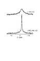
- Example 3 is a chart obtained as a result of performing 13 C CP / MAS NMR measurement on MIL-53, LiNO 3 -MIL-53 and Li-MIL-53 of Example 1.
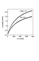
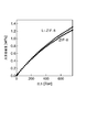
- 7 is a chart obtained as a result of 7 Li MAS NMR measurement of LiNO 3 -MIL-53 and Li-MIL-53 obtained in Example 1. It is a figure which shows the hydrogen adsorption amount measured by changing a pressure at 77K about the hydrogen storage material obtained in Example 1, and untreated MIL-53. It is a figure which shows the hydrogen adsorption amount measured by changing a pressure at 77K about the hydrogen storage material obtained in Example 2, and untreated ZIF-8.
- the hydrogen storage material which concerns on this embodiment is equipped with the porous comprised from the cluster which consists of a metal ion and oxygen ion, or a metal ion and an organic compound, and Li carry
- the porous layer is composed of clusters composed of metal ions and oxygen ions, or composed of metal ions and organic compounds.
- Examples of the “cluster consisting of metal ions and oxygen ions” used for the porous material include Zn 4 O.
- the “metal ion” used for the porous material can be widely used from light metal to heavy metal, and particularly desirable is a divalent ion of the first transition metal such as Zn (II) ion, Cu (II) ion, etc. , Divalent or trivalent ions of light metals such as Al (III) and Mg (II).
- the organic compound used for the porous metal complex is preferably an organic ligand.
- organic ligand for example, aromatic carboxylic acids and imidazoles can be used.
- aromatic carboxylic acid include terephthalic acid and 1,3,5-benzene-tribenzoic acid.
- the specific surface area of the hydrogen storage material is preferably 500 m 2 / g or more, and more preferably 1000 m 2 / g or more.
- the specific surface area of the hydrogen storage material is large, the value is, for example, about 4000 m 2 / g.
- the specific surface area of the hydrogen storage material is not limited to these values. The larger the specific surface area, the better the hydrogen storage capacity, so the larger the specific surface area is preferable.
- the specific surface area of the hydrogen storage material can be evaluated by the BET method.
- the hydrogen storage material of this embodiment can be manufactured by heating, for example, a cluster composed of metal ions and oxygen ions, or a porous layer composed of metal ions and an organic compound, and Li salt.
- the hydrogen storage material of this embodiment can be more preferably manufactured by the method shown below.
- Li salt is dissolved in water or an organic solvent
- the porous metal complex is immersed in the prepared Li solution, and left to stand overnight to impregnate the Li metal solution with the porous metal complex.
- a hydrogen storage material is obtained by heating (baking) at 200 to 600 degrees for 1 to 6 hours in a vacuum or while flowing an inert gas.
- a more preferable temperature is 300 to 400 degrees.
- Li salt to be used examples include lithium halide, lithium hydroxide, lithium carbonate, lithium nitrate, lithium acetate, and lithium sulfate, and lithium nitrate is preferable from the viewpoint of solubility in a solvent.
- a protic polar solvent such as water or alcohol, or an aprotic polar solvent such as DMF can be used.
- the hydrogen storage material of this embodiment is characterized in that Li is supported on a porous inner surface. On the inner surface, Li is supported in various forms.
- Li is carried as a counter cation of charged electrons on the porous inner surface.
- the counter anion of the Li salt is decomposed, and electrons are charged on the porous surface.
- Li is supported as the counter cation.
- chloride ions react with ethanol as a solvent to be eliminated as ethyl chloride, leaving unpaired electrons on the porous inner surface.
- Li can also be supported in the form of —COOLi. This is because part of the porous metal complex is decomposed in the firing process, the metal-carboxyl bond is cleaved, and the free carboxylate and Li are bonded.
- Li is supported on the porous inner surface.
- Li has a property of strongly adsorbing hydrogen molecules, and when Li is supported on the porous inner surface, the adsorption density of hydrogen molecules in the hydrogen storage material increases, and the hydrogen storage capacity is higher than before. Significantly improved.
- the amount of Li contained in the hydrogen storage material may be about 0.1 to 10 mass%. However, the amount of Li contained in the hydrogen storage material is not limited to this range. The larger the amount of Li introduced into the hydrogen storage material, the better the hydrogen storage capacity. Therefore, the larger the amount of Li introduced, the better.
- Example 1 A lithium nitrate ethanol solution having a lithium nitrate concentration of 0.18 mol / l was prepared. 0.25 g of a porous metal complex MIL-53 (Al) (trade name, manufactured by BASF) composed of aluminum nitrate and terephthalic acid was impregnated in 4 ml of the above lithium nitrate ethanol solution and stirred overnight. Thereafter, filtration, washing with ethanol, and drying were performed to obtain LiNO 3 -MIL-53 in which lithium nitrate (LiNO 3 ) was supported on the porous metal complex. LiNO 3 -MIL-53 was heat-treated at 300 ° C. under vacuum for 3 hours. It was confirmed that by this operation, nitrate ions were desorbed as nitride oxide, and Li-MIL-53 in which lithium ions were supported on the porous metal complex was obtained.
- MIL-53 Al
- LiNO 3 -MIL-53 LiNO 3 -MIL-53 was heat-treated
- Example 2 A lithium nitrate ethanol solution having a lithium nitrate (Wako Pure Chemical Industries, Ltd.) concentration of 0.23 mol / l was prepared.
- a porous metal complex ZIF-8 (trade name, manufactured by BASF) composed of zinc nitrate and 2-methylimidazole was impregnated in 10 ml of the above lithium nitrate ethanol solution and stirred overnight. Thereafter, filtration, washing with ethanol, and drying were performed to obtain LiNO 3 —ZIF-8 in which lithium nitrate (LiNO 3 ) was supported on the porous metal complex.
- the LiNO 3 -ZIF-8 was heat-treated at 300 ° C. under vacuum for 3 hours. It was confirmed that by this operation, nitrate ions were desorbed as nitride oxide, and Li-ZIF-8 in which lithium ions were supported on the porous metal complex was obtained.
Landscapes
- Chemical & Material Sciences (AREA)
- Organic Chemistry (AREA)
- Inorganic Chemistry (AREA)
- Chemical Kinetics & Catalysis (AREA)
- Analytical Chemistry (AREA)
- Health & Medical Sciences (AREA)
- General Health & Medical Sciences (AREA)
- Engineering & Computer Science (AREA)
- Combustion & Propulsion (AREA)
- Solid-Sorbent Or Filter-Aiding Compositions (AREA)
- Hydrogen, Water And Hydrids (AREA)
Abstract
本発明は、従来よりも優れた水素吸蔵能を有する水素吸蔵材を提供することを目的として、金属イオン及び酸素イオンからなるクラスター、又は金属イオンと有機化合物とから構成される多孔質と、当該多孔質の内表面に担持されたリチウムとを備える水素吸蔵材を提供する。本発明の水素吸蔵材は、例えば金属イオン及び酸素イオンからなるクラスター、又は金属イオンと有機化合物とから構成される多孔質と、Li塩とを加熱することにより製造することができる。
Description
本発明は、水素吸蔵材に関する。
水素は石油精製、化学工業などをはじめとしてあらゆる産業分野において広く用いられているが、特に近年、将来のエネルギーとして注目されてきており、燃料電池を中心に研究が進められている。しかし、水素ガスは熱量あたりの体積が大きく、また液化に必要なエネルギーも大きいため、そのまま貯蔵、輸送することは難しいという問題がある(例えば、非特許文献1参照)。したがって、燃料電池自動車のような移動体及び分散電源として燃料電池を用いる場合など、水素を効率的に輸送し貯蔵する技術が求められていた。
この方法として、水素を液体水素として貯蔵・運搬し使用する方法が提案されているが、液化温度が-253℃という極低温であるため取り扱いにくい、液化に必要なエネルギーが膨大でありトータルとしてのエネルギー効率が低いという問題がある(例えば、非特許文献2参照)。
これに対し、水素を高圧ガスとして運搬し使用する方法が実用化されている。しかし、この方法は危険な高圧ガスを取り扱うこと、35MPaなどのきわめて高圧にしても体積が過大になり小型化が困難なことなどに問題がある(例えば、非特許文献3参照)。
水素吸蔵合金への吸蔵も有力な方法である。しかし、水素吸蔵合金の水素吸蔵量は通常3%程度であり、移動体などに用いるためには不十分であるばかりか重量が重くなりすぎる。水素吸蔵合金は、さらに、水素放出時に多くの熱が必要であるためエネルギー効率が低くなる、システムが複雑になるなどの欠点を有している(例えば、非特許文献4参照)。
一方、水素ガスをコンパクトに運搬する技術として水素吸蔵材の利用が考えられている(下記特許文献1参照)。この技術は、水素放出が常温で可能であるのでシステムがシンプルである上、一般に水素放出に熱を必要とせずエネルギー効率が高いなどの特徴があるため、材料の開発が盛んになされている。その中で、カーボンナノチューブやカーボンナノファイバーなどの材料が高い吸蔵量を示すとの報告がある(例えば、非特許文献5参照)。しかし、それらの再現性が疑問視されており、十分な再現性を持ちながら高い吸蔵性能を持つ水素吸蔵材の開発は未だ実現したとは言えない状況である。
したがって、高い吸蔵性能を持つ材料の開発が求められており、高い吸蔵能を持つ材料として、水素と同レベルのサイズの細孔を持つ材料が検討されている。その例が前述のカーボンナノチューブやカーボンナノファイバーであるが、その他に炭素系を中心として様々な材料が試みられている。また、カーボン以外の材料として、窒化ホウ素ナノチューブ(非特許文献6)や多孔性錯体(非特許文献7)などが報告されている。しかし、一部に高い吸蔵量を示す材料の報告があるものの信頼に足り得るデータとは言えないのが現状である。
小林,「季報エネルギー総合工学」,第25巻,第4号,2003年,p.73-87
栗山,「エネルギー資源」,第24巻,第6号,2003年,p.23-27
秋山ら,「エンジンテクノロジー」,第5巻,第3号,2003年,p.43-47
秋葉,「エンジンテクノロジー」,第5巻,第3号,2003年,p.36-42頁
エー・チャンバース(A.Chambers)外,「ジャーナル・オブ・フィジカル・ケミストリー・B(J.Phys.Chem.B)」,(米国),102巻,1998年,p.4253-4256
レンツヒ・マ(Renzhi Ma)外,「ジャーナル・オブ・アメリカン・ケミカル・ソウサイアティー(J.Am.Chem.Soc.)」,(米国),124巻,2002年,p.7672-7673
ナタニール・エル・ロシ(Nathaniel.L.Rosi)外,「サイエンス(Science)」,(英国),300巻,2003年,p.1127-1129
近年、水素の有用性が高まるに伴って、水素吸蔵材の水素吸蔵能の更なる向上が望まれている。水素吸蔵能を向上させる方法としては、水素吸蔵材の比表面積を増加させることにより、水素吸蔵材の表面に物理吸着する水素の量を増加させることが挙げられる。しかし、単に水素の物理吸着量を増加させるだけでは、所望の水素吸蔵能を達成することは容易ではない。
本発明は、上記従来技術の有する課題に鑑みてなされたものであり、従来よりも優れた水素吸蔵能を有する水素吸蔵材を提供することを目的とする。
上記目的を達成するために、本発明に係る水素吸蔵材は、金属イオン及び酸素イオンからなるクラスター、又は金属イオンと有機化合物とから構成される多孔質と、当該多孔質の内表面(多孔質の細孔内の内壁の表面)に担持されたリチウム(Li)と、を備える。
上記本発明に係る水素吸蔵材は、水素との親和性が高いLiが多孔質の内表面に担持されているため、従来の多孔性材料からなる水素吸蔵材に比べて、優れた水素吸蔵能を有する。なお、Liは原子状のLiであっても、イオン状のLiであってもよいが、通常は1価のLiカチオンである。また、Liは多孔質の外表面(細孔部以外の多孔質の表面)に担持されていてもよい。
上記有機化合物は有機配位子であり、かつ前記多孔質は多孔性金属錯体であることが好ましい。これにより、水素吸蔵材の安定性が向上する。
上述の水素吸蔵材は、例えば金属イオン及び酸素イオンからなるクラスター、又は金属イオンと有機化合物とから構成される多孔質と、Li塩とを加熱することにより製造することができる。
本発明によれば、従来よりも優れた水素吸蔵能を有する水素吸蔵材を提供することができる。
以下、本発明の好適な一実施形態について詳細に説明する。本実施形態に係る水素吸蔵材は、金属イオン及び酸素イオンからなるクラスター、又は金属イオンと有機化合物とから構成される多孔質と、当該多孔質の内表面に担持されたLiと、を備える。
多孔質は、金属イオン及び酸素イオンからなるクラスター、又は金属イオンと有機化合物とからなる。
多孔質に用いる「金属イオン及び酸素イオンからなるクラスター」としては、例えばZn4Oが挙げられる。
また、多孔質に用いる「金属イオン」としては、軽金属から重金属まで幅広く使用することができるが、特に望ましいのはZn(II)イオン、Cu(II)イオンなどの第1遷移金属の2価イオン、Al(III)、Mg(II)などの軽金属の2価又は3価イオンである。
多孔質に用いる「金属イオン及び酸素イオンからなるクラスター」としては、例えばZn4Oが挙げられる。
また、多孔質に用いる「金属イオン」としては、軽金属から重金属まで幅広く使用することができるが、特に望ましいのはZn(II)イオン、Cu(II)イオンなどの第1遷移金属の2価イオン、Al(III)、Mg(II)などの軽金属の2価又は3価イオンである。
多孔性金属錯体に用いる有機化合物は、有機配位子であることが望ましい。有機配位子としては、例えば芳香族カルボン酸、イミダゾール類を用いることができる。芳香族カルボン酸の具体例としては、テレフタル酸や1,3,5-ベンゼン-トリ安息香酸が挙げられる。
水素吸蔵材の比表面積は、500m2/g以上であることが好ましく、1000m2/g以上であることがより好ましい。水素吸蔵材の比表面積が大きい場合、その値は例えば4000m2/g程度である。ただし、水素吸蔵材の比表面積はこれらの値に限定されない。比表面積が大きいほど水素吸蔵能が向上するので、比表面積は大きいほど好ましい。水素吸蔵材の比表面積は、BET法によって評価することができる。
本実施形態の水素吸蔵材は、例えば金属イオン及び酸素イオンからなるクラスター、又は金属イオンと有機化合物とから構成される多孔質と、Li塩と、を加熱することにより製造することができる。
本実施形態の水素吸蔵材は、より好適には以下に示す方法により製造することができる。
Li塩を水や有機溶媒に溶解させ、調製したLi溶液に多孔性金属錯体を浸し、1晩静置することで多孔性金属錯体にLi溶液を含浸させる。次に、真空中又は不活性ガスを流しながら200~600度、1~6時間加熱(焼成)することにより水素吸蔵材が得られる。より好ましい温度は300~400度である。
Li塩を水や有機溶媒に溶解させ、調製したLi溶液に多孔性金属錯体を浸し、1晩静置することで多孔性金属錯体にLi溶液を含浸させる。次に、真空中又は不活性ガスを流しながら200~600度、1~6時間加熱(焼成)することにより水素吸蔵材が得られる。より好ましい温度は300~400度である。
用いるLi塩としては、リチウムハロゲン化物、水酸化リチウム、炭酸リチウム、硝酸リチウム、酢酸リチウム、硫酸リチウムなどが挙げられるが、溶媒への溶解性の観点から硝酸リチウムが望ましい。
また、Li塩を溶解させる溶媒としては、水やアルコールなどのプロトン性極性溶媒、DMFなど非プロトン性極性溶媒を用いることができる。
本実施形態の水素吸蔵材は、多孔質の内表面にLiが担持されていることを特徴とする。内表面では、Liは多様な形で担持されている。
例えば、Liは多孔質の内表面に帯電した電子のカウンターカチオンとして担持されている。Li塩のカウンターアニオンは分解され、電子が多孔質の表面に帯電される。そのカウンターカチオンとしてLiが担持されている。例えば、塩化リチウムを用いた場合には、塩化物イオンが溶媒のエタノールと反応して塩化エチルとして脱離し、多孔質の内表面に不対電子が残る。
また、有機配位子がカルボン酸である場合には、Liは-COOLiの形でも担持され得る。焼成過程において、多孔性金属錯体の一部が分解し、金属-カルボキシル基結合が切断され、フリーとなったカルボキシレートとLiが結合するためである。
本実施形態の水素吸蔵材においては、多孔質の内表面にLiが担持されている。Liは水素分子を強く吸着する性質を有しており、Liが多孔質の内表面に担持されることによって、水素吸蔵材における水素分子の吸着密度が増加して、水素吸蔵能が従来に比べて著しく向上する。
水素吸蔵材に含まれるLiの量は、0.1~10mass%程度であればよい。ただし、水素吸蔵材に含まれるLiの量はこの範囲に限定されない。水素吸蔵材へのLiの導入量が大きいほど水素吸蔵能が向上するので、Liの導入量は多いほど好ましい。
以上、本発明に係る水素吸蔵材及びその製造方法の好適な一実施形態について詳細に説明したが、本発明は上記実施形態に限定されるものではない。
以下、実施例及び比較例に基づき本発明をさらに具体的に説明するが、本発明は以下の実施例に何ら限定されるものではない。
[水素吸蔵材の合成]
(実施例1)
硝酸リチウム濃度0.18mol/lの硝酸リチウムエタノール溶液を調製した。
硝酸アルミニウムとテレフタル酸から構成される多孔性金属錯体MIL-53(Al)(商品名、BASF社製)0.25gを、上述の硝酸リチウムエタノール溶液4mlに含浸し、一晩攪拌した。その後、濾過、エタノールによる洗浄、乾燥を行い、硝酸リチウム(LiNO3)が多孔性金属錯体上に担持されたLiNO3-MIL-53を得た。
LiNO3-MIL-53を真空下300℃において熱処理を3時間行った。この操作によって硝酸イオンが窒化酸化物として脱離し、リチウムイオンが多孔性金属錯体上に担持されたLi-MIL-53が得られていることを確認した。
(実施例1)
硝酸リチウム濃度0.18mol/lの硝酸リチウムエタノール溶液を調製した。
硝酸アルミニウムとテレフタル酸から構成される多孔性金属錯体MIL-53(Al)(商品名、BASF社製)0.25gを、上述の硝酸リチウムエタノール溶液4mlに含浸し、一晩攪拌した。その後、濾過、エタノールによる洗浄、乾燥を行い、硝酸リチウム(LiNO3)が多孔性金属錯体上に担持されたLiNO3-MIL-53を得た。
LiNO3-MIL-53を真空下300℃において熱処理を3時間行った。この操作によって硝酸イオンが窒化酸化物として脱離し、リチウムイオンが多孔性金属錯体上に担持されたLi-MIL-53が得られていることを確認した。
(実施例2)
硝酸リチウム(和光純薬工業株式会社)濃度0.23mol/lの硝酸リチウムエタノール溶液を調製した。
硝酸亜鉛と2-メチルイミダゾールから構成される多孔性金属錯体ZIF-8(商品名、BASF社製)0.5gを、上述の硝酸リチウムエタノール溶液10mlに含浸し、一晩攪拌した。その後、濾過、エタノールによる洗浄、乾燥を行い、硝酸リチウム(LiNO3)が多孔性金属錯体上に担持されたLiNO3-ZIF-8を得た。
LiNO3-ZIF-8を真空下300℃において熱処理を3時間行った。この操作によって硝酸イオンが窒化酸化物として脱離し、リチウムイオンが多孔性金属錯体上に担持されたLi-ZIF-8が得られていることを確認した。
硝酸リチウム(和光純薬工業株式会社)濃度0.23mol/lの硝酸リチウムエタノール溶液を調製した。
硝酸亜鉛と2-メチルイミダゾールから構成される多孔性金属錯体ZIF-8(商品名、BASF社製)0.5gを、上述の硝酸リチウムエタノール溶液10mlに含浸し、一晩攪拌した。その後、濾過、エタノールによる洗浄、乾燥を行い、硝酸リチウム(LiNO3)が多孔性金属錯体上に担持されたLiNO3-ZIF-8を得た。
LiNO3-ZIF-8を真空下300℃において熱処理を3時間行った。この操作によって硝酸イオンが窒化酸化物として脱離し、リチウムイオンが多孔性金属錯体上に担持されたLi-ZIF-8が得られていることを確認した。
[水素吸蔵材の評価]
(13C CP/MAS NMR測定)
実施例1のMIL-53、LiNO3-MIL-53及びLi-MIL-53について、13C CP/MAS NMR測定を行った。その結果、得られたチャートを図1に示す。図1から明らかであるように、Li-MIL-53には、MIL-53及びLiNO3-MIL-53には存在しないδ=175.6ppmのピークが観察された。このピークは、カルボキシル基とLiとが結合していることに由来するものであると考えられる。
(13C CP/MAS NMR測定)
実施例1のMIL-53、LiNO3-MIL-53及びLi-MIL-53について、13C CP/MAS NMR測定を行った。その結果、得られたチャートを図1に示す。図1から明らかであるように、Li-MIL-53には、MIL-53及びLiNO3-MIL-53には存在しないδ=175.6ppmのピークが観察された。このピークは、カルボキシル基とLiとが結合していることに由来するものであると考えられる。
(7Li MAS NMR測定)
実施例1で得られたLiNO3-MIL-53及びLi-MIL-53について、7Li MAS NMR測定を行った。その結果、得られたチャートを図2に示す。図2から明らかであるように、Li-MIL-53のピークはブロード化しており、Liが多孔質の細孔内に存在し、細孔壁からの相互作用を受けている、すなわち多孔質の内表面にLiが担持されていることが確認できる。
実施例1で得られたLiNO3-MIL-53及びLi-MIL-53について、7Li MAS NMR測定を行った。その結果、得られたチャートを図2に示す。図2から明らかであるように、Li-MIL-53のピークはブロード化しており、Liが多孔質の細孔内に存在し、細孔壁からの相互作用を受けている、すなわち多孔質の内表面にLiが担持されていることが確認できる。
(水素吸着量の測定)
実施例1~2で得られた水素吸蔵材、未処理のMIL-53、及び未処理のZIF-8について、77K、760torrにおける水素吸着量の測定を行った。その結果を表1に示す。また、実施例1で得られた水素吸蔵材及び未処理のMIL-53について、77Kで圧力を変化させて測定した水素吸着量を図3に、実施例2で得られた水素吸蔵材及び未処理のZIF-8について、77Kで圧力を変化させて測定した水素吸着量を図4に示す。
実施例1~2で得られた水素吸蔵材、未処理のMIL-53、及び未処理のZIF-8について、77K、760torrにおける水素吸着量の測定を行った。その結果を表1に示す。また、実施例1で得られた水素吸蔵材及び未処理のMIL-53について、77Kで圧力を変化させて測定した水素吸着量を図3に、実施例2で得られた水素吸蔵材及び未処理のZIF-8について、77Kで圧力を変化させて測定した水素吸着量を図4に示す。
(比表面積の測定)
実施例1~2で得られた水素吸蔵材、未処理のMIL-53、及び未処理のZIF-8窒素吸着測定を行い、BET法によりその比表面積を求めた。その結果を表1に示す。
実施例1~2で得られた水素吸蔵材、未処理のMIL-53、及び未処理のZIF-8窒素吸着測定を行い、BET法によりその比表面積を求めた。その結果を表1に示す。

表1から明らかであるように、多孔質の内表面にLiが担持された実施例1、2の水素吸蔵材によれば、比表面積の大小にかかわらず未処理の多孔質よりも水素吸着量が増大する。
Claims (3)
- 金属イオン及び酸素イオンからなるクラスター、又は金属イオンと有機化合物とから構成される多孔質と、
当該多孔質の内表面に担持されたLiと、
を備える、水素吸蔵材。 - 前記有機化合物が有機配位子であり、かつ前記多孔質が多孔性金属錯体である、請求項1に記載の水素吸蔵材。
- 金属イオン及び酸素イオンからなるクラスター、又は金属イオンと有機化合物とから構成される多孔質と、Li塩と、を加熱することにより製造される、請求項1又は2に記載の水素吸蔵材。
Applications Claiming Priority (2)
| Application Number | Priority Date | Filing Date | Title |
|---|---|---|---|
| JP2010-033605 | 2010-02-18 | ||
| JP2010033605A JP2011167630A (ja) | 2010-02-18 | 2010-02-18 | 水素吸蔵材 |
Publications (1)
| Publication Number | Publication Date |
|---|---|
| WO2011102173A1 true WO2011102173A1 (ja) | 2011-08-25 |
Family
ID=44482775
Family Applications (1)
| Application Number | Title | Priority Date | Filing Date |
|---|---|---|---|
| PCT/JP2011/050857 Ceased WO2011102173A1 (ja) | 2010-02-18 | 2011-01-19 | 水素吸蔵材 |
Country Status (2)
| Country | Link |
|---|---|
| JP (1) | JP2011167630A (ja) |
| WO (1) | WO2011102173A1 (ja) |
Cited By (1)
| Publication number | Priority date | Publication date | Assignee | Title |
|---|---|---|---|---|
| WO2013035702A1 (ja) * | 2011-09-05 | 2013-03-14 | 株式会社クラレ | 吸着材 |
-
2010
- 2010-02-18 JP JP2010033605A patent/JP2011167630A/ja active Pending
-
2011
- 2011-01-19 WO PCT/JP2011/050857 patent/WO2011102173A1/ja not_active Ceased
Non-Patent Citations (4)
| Title |
|---|
| DINCA MIRCEA ET AL.: "High-Enthalpy Hydrogen Adsorption in Cation-Exchanged Variants of the Microporous Metal-Organic Framework Mn3[(Mn4Cl)3(BTT)8 (CH30H)10]2", J AM CHEM SOC, vol. 129, no. 36, 12 September 2007 (2007-09-12), CALIFORNIA, pages 11172 - 11176 * |
| HAN SANG SOO ET AL.: "Lithium-Doped Metal-Organic Frameworks for Reversible H2 Storage at Ambient Temperature", J AM CHEM SOC, vol. 129, no. 27, 11 July 2007 (2007-07-11), CALIFORNIA, pages 8422 - 8423 * |
| MAVRANDONAKIS ANDREAS ET AL.: "Enhancement of Hydrogen Adsorption in Metal-Organic Frameworks by the Incorporation of the Sulfonate Group and Li Cations.", A MULTISCALE COMPUTATIONAL STUDY, J AM CHEM SOC, vol. 131, no. 37, 23 September 2009 (2009-09-23), CRETE, GRC, pages 13410 - 13414 * |
| MULFORT KAREN L. ET AL.: "Alkali Metal Cation Effects on Hydrogen Uptake and Binding in Metal-Organic Frameworks", INORG CHEM, vol. 47, no. 18, 15 September 2008 (2008-09-15), ILLINOIS, pages 7936 - 7938 * |
Cited By (2)
| Publication number | Priority date | Publication date | Assignee | Title |
|---|---|---|---|---|
| WO2013035702A1 (ja) * | 2011-09-05 | 2013-03-14 | 株式会社クラレ | 吸着材 |
| US9192913B2 (en) | 2011-09-05 | 2015-11-24 | Kuraray Co., Ltd. | Adsorbent |
Also Published As
| Publication number | Publication date |
|---|---|
| JP2011167630A (ja) | 2011-09-01 |
Similar Documents
| Publication | Publication Date | Title |
|---|---|---|
| Zhong et al. | Yolk–Shell MnO@ ZnMn2O4/N–C Nanorods Derived from α‐MnO2/ZIF‐8 as Anode Materials for Lithium Ion Batteries | |
| Indra et al. | Metal organic framework derived materials: progress and prospects for the energy conversion and storage | |
| Zhuang et al. | ZIF-67/COF-derived highly dispersed Co3O4/N-doped porous carbon with excellent performance for oxygen evolution reaction and Li-ion batteries | |
| He et al. | A series of metal–organic frameworks with high methane uptake and an empirical equation for predicting methane storage capacity | |
| Choi et al. | Supercapacitors of nanocrystalline metal–organic frameworks | |
| Wen et al. | A boron imidazolate framework with mechanochromic and electrocatalytic properties | |
| JP2014055110A (ja) | ミクロポーラス炭素系材料の製造方法 | |
| JP2010115636A (ja) | ミクロポーラス炭素系材料、ミクロポーラス炭素系材料の製造方法及びミクロポーラス系炭素材料を用いた水素吸蔵方法 | |
| JP2018021217A (ja) | 二酸化炭素還元装置 | |
| Zhao et al. | Toward the next generation of sustainable aluminum-ion batteries: a review | |
| US20100069236A1 (en) | Methods for manfacturing li-doped silica nanotube using anodic aluminum oxide template and use of the li-doped silica nanotube for energy storage | |
| Meng et al. | Post nitrogen electrocatalysis era from Li–N2 batteries to Zn–N2 batteries | |
| He et al. | Development of g-C3N4 activated hollow carbon spheres with good performance for oxygen reduction and selective capture of acid gases | |
| Wang et al. | Multifunctional amino-functionalized Zr-based metal-organic frameworks: a breakthrough in enhancing the stability and performance of Ni-rich cathode Li metal batteries in water-prone environments | |
| Lionet et al. | Bimetallic MOF-templated synthesis of alloy nanoparticle-embedded porous carbons for oxygen evolution and reduction reactions | |
| JP6551145B2 (ja) | 二酸化炭素還元用電極、容器、及び二酸化炭素還元装置 | |
| Hu et al. | Optimizing Prussian Blue Analogues for Potassium‐Ion Batteries: Advanced Strategies | |
| Li et al. | Direct conversion of metal organic frameworks into porous rugby phosphides by plasma for oxygen evolution | |
| WO2011102173A1 (ja) | 水素吸蔵材 | |
| CN104240965A (zh) | 一种具有孔结构的石墨烯/二氧化硅/聚苯胺复合材料及其制备方法与应用 | |
| Park et al. | Iron Nanoparticles on Porous Carbon Discs: Electrocatalysts with Over 30% Energy Efficiencies for the Production of Ammonia from Nitrate | |
| JP4893918B2 (ja) | 含窒素炭素系電極触媒 | |
| Liu et al. | Phenoxazine-based COFs for CO 2/N 2 separation and organic dye adsorption | |
| WO2011046001A1 (ja) | 水素吸蔵材 | |
| JP5509415B2 (ja) | 水素吸蔵材料 |
Legal Events
| Date | Code | Title | Description |
|---|---|---|---|
| 121 | Ep: the epo has been informed by wipo that ep was designated in this application |
Ref document number: 11744462 Country of ref document: EP Kind code of ref document: A1 |
|
| NENP | Non-entry into the national phase |
Ref country code: DE |
|
| 122 | Ep: pct application non-entry in european phase |
Ref document number: 11744462 Country of ref document: EP Kind code of ref document: A1 |