WO2011102018A1 - 放射線治療装置制御装置および放射線治療装置の作動方法 - Google Patents
放射線治療装置制御装置および放射線治療装置の作動方法 Download PDFInfo
- Publication number
- WO2011102018A1 WO2011102018A1 PCT/JP2010/068928 JP2010068928W WO2011102018A1 WO 2011102018 A1 WO2011102018 A1 WO 2011102018A1 JP 2010068928 W JP2010068928 W JP 2010068928W WO 2011102018 A1 WO2011102018 A1 WO 2011102018A1
- Authority
- WO
- WIPO (PCT)
- Prior art keywords
- target position
- time
- corrected
- radiation
- indicates
- Prior art date
Links
Images


Classifications
-
- A—HUMAN NECESSITIES
- A61—MEDICAL OR VETERINARY SCIENCE; HYGIENE
- A61N—ELECTROTHERAPY; MAGNETOTHERAPY; RADIATION THERAPY; ULTRASOUND THERAPY
- A61N5/00—Radiation therapy
- A61N5/10—X-ray therapy; Gamma-ray therapy; Particle-irradiation therapy
- A61N5/1048—Monitoring, verifying, controlling systems and methods
- A61N5/1064—Monitoring, verifying, controlling systems and methods for adjusting radiation treatment in response to monitoring
- A61N5/1065—Beam adjustment
-
- A—HUMAN NECESSITIES
- A61—MEDICAL OR VETERINARY SCIENCE; HYGIENE
- A61N—ELECTROTHERAPY; MAGNETOTHERAPY; RADIATION THERAPY; ULTRASOUND THERAPY
- A61N5/00—Radiation therapy
- A61N5/10—X-ray therapy; Gamma-ray therapy; Particle-irradiation therapy
- A61N5/1048—Monitoring, verifying, controlling systems and methods
- A61N5/1049—Monitoring, verifying, controlling systems and methods for verifying the position of the patient with respect to the radiation beam
- A61N2005/1061—Monitoring, verifying, controlling systems and methods for verifying the position of the patient with respect to the radiation beam using an x-ray imaging system having a separate imaging source
Definitions
- the present invention relates to a radiotherapy apparatus control apparatus and an operation method of the radiotherapy apparatus, and more particularly to a radiotherapy apparatus control apparatus and an operation method of the radiotherapy apparatus used when treating a patient by irradiating an affected area with radiation. .
- the radiotherapy apparatus that performs the radiotherapy includes a therapeutic radiation irradiation apparatus that exposes the therapeutic radiation, a sensor that measures the position of the affected area of the patient, and the therapeutic radiation that is irradiated to the measured position. And a drive device for moving the therapeutic radiation irradiation device. According to such a radiotherapy apparatus, even when the affected part moves with the patient's breathing or the like, it is possible to irradiate the affected part with therapeutic radiation.
- Such radiotherapy is desired to have a high therapeutic effect, and the therapeutic radiation is less exposed to normal cells than the dose exposed to the affected cells. Is desired.
- the radiotherapy apparatus is desired to expose the therapeutic radiation to the affected area with higher accuracy, and it is desired to move the therapeutic radiation irradiation apparatus with higher accuracy.
- the radiotherapy apparatus is further desired to have a high responsiveness of the drive device and to be stable in the operation of the drive device.
- Japanese Patent Laid-Open No. 2004-65808 discloses that the irradiation field can be formed from a wide irradiation field to a fine irregular irradiation field, shortening the irradiation time and appropriately irradiating the patient's body movement, and enabling miniaturization.
- a radiotherapy device is disclosed.
- the radiotherapy apparatus includes an electron beam source, a deflecting electromagnet that changes the direction of the electron beam, a vacuum window that allows the electron beam to pass while maintaining a vacuum, a scattering foil that scatters the electron beam, A target for converting electron beams into X-rays, a flattening filter for making the dose distribution of electron beams and X-rays uniform on the irradiation surface, a collimator for narrowing down electron beams and X-rays, and electron beam and X-ray doses
- a radiation therapy apparatus including an irradiation head composed of a dosimeter to measure and a gantry arm that holds the irradiation head, wherein the electron beam source and the deflection electromagnet are coupled by a vacuum rotary joint, and the gantry Rotating means for swinging the irradiation head about an axis parallel to the arm rotation axis and passing through the virtual source position is provided.
- Japanese Patent Application Laid-Open No. 2006-21046 discloses a radiotherapy apparatus that can monitor the state of a treatment field in real time even during radiation irradiation treatment.
- the radiotherapy apparatus is provided movably on the O-type gantry, the O-type gantry, a radiation irradiation head for irradiating therapeutic radiation to the treatment field of the subject, and movably provided on the O-type gantry.
- An X-ray source that irradiates diagnostic X-rays to the treatment field of the subject, and a movable X-ray that is transmitted to the O-type gantry and detects the transmitted X-rays of the diagnostic X-ray transmitted through the subject.
- a sensor array that outputs as diagnostic image data, and the sensor array is provided at a target position across the radiation irradiation head, and moves on the O-type gantry in conjunction with the movement of the radiation irradiation head.
- the X-ray source moves in conjunction with the movement of the sensor array.
- An object of the present invention is to prevent a motor trip of a drive device that moves a radiation irradiation device that exposes therapeutic radiation, and to provide a radiation therapy device control device and a radiation therapy device that move the radiation irradiation device with high accuracy. It is to provide an operating method.
- a radiotherapy apparatus control apparatus includes an irradiation target detection unit that calculates a target position based on a specific part position where a specific part inside a subject is arranged at a measurement time, and radiation irradiation that exposes therapeutic radiation. And a swing position control unit that controls a drive device that moves the radiation irradiation device so that the device is directed to the corrected target position at a control time after the measurement time.
- the corrected target position indicates a position closer to the position where the radiation irradiating device is directed immediately before the control time than the target position when the control time is included in the preparation period.
- the corrected target position indicates the target position when the control time is included in the treatment period after the preparation period.
- Such a radiotherapy device control device controls the drive device so that the radiation irradiation device moves slowly, and then controls the drive device so that the radiation irradiation device tracks the specific part.
- the motor trip of the drive device can be prevented, and the radiation irradiation device can be moved with high accuracy.
- the post-correction target position indicates a position that internally divides a line segment connecting the initial position and the target position when the control time is included in the preparation period.
- the internal ratio at which the corrected target position internally divides the line segment is preferably calculated so that the corrected target position gradually approaches the target position as time passes.
- the amount of change in the internal ratio per unit time is constant.
- the swing position control unit calculates an operation amount based on a position deviation between the corrected target position and a position where the radiation irradiation device is directed, and calculates a coefficient based on the position deviation. And a multiplier that multiplies the manipulated variable by the coefficient to calculate a corrected manipulated variable. The coefficient simply decreases with respect to the absolute value of the position deviation.
- the driving device is preferably controlled based on the corrected operation amount.
- the swing position control unit further includes a feed forward unit that calculates a feed forward operation amount based on the change in the corrected target position. At this time, the drive device is preferably controlled based on the feedforward operation amount.
- the swing position control unit further includes a temperature drift correction unit that calculates a temperature drift amount based on a temperature of a device that generates an electric signal supplied to the drive device when the drive device is controlled. .
- the drive is preferably controlled further based on the amount of temperature drift.
- An operation method of a radiotherapy apparatus includes a step of calculating a target position based on a specific part position where a specific part inside a subject is arranged at a measurement time, and a radiation irradiating apparatus for exposing therapeutic radiation. And a step of controlling a driving device that moves the radiation irradiation apparatus so as to be directed to the corrected target position at a control time after the measurement time.
- the corrected target position indicates a position closer to the position where the radiation irradiating device is directed immediately before the control time than the target position when the control time is included in the preparation period.
- the target position is indicated.
- the radiotherapy apparatus control apparatus controls the drive apparatus so that the radiation irradiation apparatus moves slowly, and then the radiation irradiation apparatus tracks the specific part. Further, by controlling the drive device, it is possible to prevent the motor trip of the drive device and to move the radiation irradiation device with high accuracy.
- the post-correction target position indicates a position that internally divides a line segment connecting the initial position and the target position when the control time is included in the preparation period.
- the internal ratio at which the corrected target position internally divides the line segment is calculated so that the corrected target position gradually approaches the target position as time passes.
- the amount of change in the internal ratio per unit time is constant.
- the operation method of the radiotherapy apparatus includes a step of calculating an operation amount based on a position deviation between the corrected target position and a position where the radiation irradiation apparatus is directed, and a coefficient is calculated based on the position deviation. And a step of multiplying the operation amount by the coefficient to calculate a corrected operation amount.
- the coefficient simply decreases with respect to the absolute value of the position deviation.
- the driving device is preferably controlled based on the corrected operation amount.
- the operation method of the radiotherapy apparatus further includes a step of calculating a feedforward manipulated variable based on a change in the corrected target position.
- the drive device is preferably controlled based on the feedforward operation amount.
- the operation method of the radiotherapy apparatus further includes a step of calculating a temperature drift amount based on a temperature of the apparatus that generates an electric signal supplied to the driving apparatus when the driving apparatus is controlled. .
- the drive device is preferably controlled based on the temperature drift amount.
- the radiation therapy apparatus control apparatus and radiation therapy apparatus operating method according to the present invention prevents a motor trip of a driving apparatus that moves the radiation irradiation apparatus when moving the radiation irradiation apparatus that exposes the therapeutic radiation, and
- the radiation irradiation apparatus can be moved with high accuracy.
- FIG. 1 is a perspective view showing a radiation therapy apparatus.
- FIG. 2 is a block diagram showing the radiotherapy apparatus control apparatus.
- FIG. 3 is a block diagram showing the swing position control unit.
- FIG. 4 is a graph showing changes in coefficients calculated by the target position correction unit.
- FIG. 5 is a graph showing the interpolation command value calculated by the interpolation command value creation unit.
- FIG. 6 is a graph showing the relationship between the input and output of the D / A conversion circuit.
- FIG. 7 is a block diagram illustrating the operation amount calculation unit.
- FIG. 8 is a graph showing the relationship between the position deviation and the coefficient.
- FIG. 9 is a graph showing changes in the target position, changes in the corrected target position, and changes in the interpolation command value.
- FIG. 10 is a graph showing changes in other coefficients calculated by the target position correction unit.
- the radiotherapy apparatus controller 10 is applied to a radiotherapy system as shown in FIG.
- the radiotherapy system includes a radiotherapy apparatus control apparatus 10 and a radiotherapy apparatus 3.
- the radiotherapy apparatus control apparatus 10 is a computer exemplified by a personal computer.
- the radiotherapy apparatus controller 10 and the radiotherapy apparatus 3 are connected to each other so that information can be transmitted in both directions.
- the radiotherapy device 3 includes an O-ring 12, a traveling gantry 14, and a therapeutic radiation irradiation device 16.
- the O-ring 12 is formed in a ring shape, and is supported by a foundation so as to be rotatable about a rotation shaft 17.
- the rotating shaft 17 is parallel to the vertical direction.
- the traveling gantry 14 is formed in a ring shape, is disposed inside the ring of the O-ring 12, and is supported by the O-ring 12 so as to be rotatable about a rotation shaft 18.
- the rotating shaft 18 is perpendicular to the vertical direction and passes through an isocenter 19 included in the rotating shaft 17.
- the rotating shaft 18 is fixed to the O-ring 12, that is, rotates around the rotating shaft 17 together with the O-ring 12.
- the therapeutic radiation irradiation device 16 is disposed inside the ring of the traveling gantry 14.
- the therapeutic radiation irradiation device 16 is supported by the traveling gantry 14 so as to be rotatable about the tilt shaft 21 and rotatable about the pan shaft 22.
- the pan axis 22 is fixed to the traveling gantry 14 and is parallel to the rotation axis 18 without intersecting the rotation axis 18.
- the tilt axis 21 is orthogonal to the pan axis 22. The intersection of the tilt axis 21 and the pan axis 22 is separated from the isocenter 19 by 1 m.
- the radiotherapy apparatus 3 further includes a turning drive device 11 and a swing device 15 and a travel drive device (not shown).
- the turning drive device 11 rotates the O-ring 12 around the rotation shaft 17 by being controlled by the radiotherapy device control device 10. Further, the turning drive device 11 measures a turning angle at which the O-ring 12 is disposed with respect to the foundation, and outputs the turning angle to the radiotherapy device control device 10.
- the traveling drive device rotates the traveling gantry 14 around the rotation shaft 18 by being controlled by the radiotherapy device control device 10.
- the traveling drive apparatus further measures the gantry angle at which the traveling gantry 14 is disposed with respect to the O-ring 12 and outputs the gantry angle to the radiation therapy apparatus control apparatus 10.
- the head swing device 15 is controlled by the radiotherapy device controller 10 to rotate the therapeutic radiation irradiation device 16 about the tilt axis 21 and rotate the therapeutic radiation irradiation device 16 about the pan axis 22. .
- the head swing device 15 further measures the tilt angle at which the therapeutic radiation irradiation device 16 rotates with respect to the traveling gantry 14 about the tilt axis 21 and outputs the tilt angle to the radiation therapy device control device 10.
- the head swing device 15 further measures the pan angle at which the therapeutic radiation irradiation device 16 rotates with respect to the traveling gantry 14 around the pan axis 22 and outputs the pan angle to the radiotherapy device control device 10.
- the therapeutic radiation irradiation device 16 is exposed to the therapeutic radiation 23 by being controlled by the radiotherapy device control device 10.
- the therapeutic radiation 23 is a cone beam having an apex at the intersection where the pan axis 22 and the tilt axis 21 intersect.
- the therapeutic radiation 23 is formed to have a uniform intensity distribution.
- the therapeutic radiation irradiation device 16 includes a multi-leaf collimator 20.
- the multi-leaf collimator 20 is fixed to the therapeutic radiation irradiation device 16 so as to be disposed in a region where the therapeutic radiation 23 travels.
- the multi-leaf collimator 20 is controlled by the radiotherapy apparatus controller 10 to shield a part of the therapeutic radiation 23 and change the shape of the irradiation field when the therapeutic radiation 23 is irradiated to the patient.
- the therapeutic radiation 23 is driven to rotate. Even if the O-ring 12 is rotated by the apparatus 11 or the traveling gantry 14 is rotated by the traveling drive apparatus, the O-ring 12 always passes through the isocenter 19 at all times. In other words, the therapeutic radiation 23 can be irradiated from any direction toward the isocenter 19 by running and turning.
- the radiotherapy apparatus 3 further includes a plurality of imager systems. That is, the radiotherapy apparatus 3 includes a first diagnostic X-ray source 24, a second diagnostic X-ray source 25, a first sensor array 32, and a second sensor array 33.
- the first diagnostic X-ray source 24 is supported by the traveling gantry 14 and an angle formed by a line segment connecting the first diagnostic X-ray source 24 from the isocenter 19 and a line segment connecting the therapeutic radiation irradiation device 16 from the isocenter 19. Is disposed inside the ring of the traveling gantry 14 so that is an acute angle.
- the second diagnostic X-ray source 25 is supported by the traveling gantry 14, and an angle formed by a line segment connecting the second diagnostic X-ray source 25 from the isocenter 19 and a line segment connecting the therapeutic radiation irradiation device 16 from the isocenter 19. Is disposed inside the ring of the traveling gantry 14 so that is an acute angle. In the second diagnostic X-ray source 25, the angle formed by the line connecting the isocenter 19 and the first diagnostic X-ray source 24 and the line connecting the isocenter 19 and the second diagnostic X-ray source 25 is a right angle ( (90 degrees).
- the first sensor array 32 is supported by the traveling gantry 14 and is disposed so as to face the first diagnostic X-ray source 24 via the isocenter 19.
- the second sensor array 33 is supported by the traveling gantry 14 and is disposed so as to face the second diagnostic X-ray source 25 via the isocenter 19.
- the first diagnostic X-ray source 24 is controlled by the radiation therapy apparatus control apparatus 10 to expose the first diagnostic X-ray 35 toward the isocenter 19 at a predetermined timing.
- the first diagnostic X-ray 35 is a conical cone beam that is exposed from one point of the first diagnostic X-ray source 24 and has the one point as a vertex.
- the second diagnostic X-ray source 25 is controlled by the radiation therapy apparatus control apparatus 10 to irradiate the second diagnostic X-ray 36 toward the isocenter 19 at a predetermined timing.
- the second diagnostic X-ray 36 is a conical cone beam that is irradiated from one point of the second diagnostic X-ray source 25 and has the one point as a vertex.
- the first sensor array 32 includes a light receiving unit.
- the first sensor array 32 generates a first fluoroscopic image based on the X-rays received by the light receiving unit by being controlled by the radiation therapy apparatus control apparatus 10.
- the second sensor array 33 includes a light receiving unit.
- the second sensor array 33 generates a second fluoroscopic image based on the X-rays received by the light receiving unit by being controlled by the radiation therapy apparatus control apparatus 10.
- the perspective image is formed of a plurality of pixels.
- the plurality of pixels are arranged in a matrix on the perspective image, and are associated with luminance.
- the fluoroscopic image projects a subject by the luminance corresponding to each of the plurality of pixels being colored on each of the plurality of pixels.
- Examples of the first sensor array 32 and the second sensor array 33 include FPD (Flat Panel Detector) and X-ray II (Image Intensifier).
- a fluoroscopic image centered on the isocenter 19 can be generated based on the image signal obtained by the first sensor array 32 and the second sensor array 33.
- the radiotherapy apparatus 3 further includes a couch 41 and a couch driving device 42.
- the couch 41 is supported by a base so as to be able to rotate around the x-axis, y-axis, and z-axis, and to be able to translate in parallel to the x-axis, y-axis, and z-axis.
- the x-axis, y-axis, and z-axis are orthogonal to each other.
- the couch 41 is used when a patient 43 to be treated by the radiation treatment system lies down.
- the couch 41 includes a fixture not shown. The fixture fixes the patient 43 to the couch 41 so that the patient 43 does not move.
- the couch driving device 42 is rotated by the couch 41 and moved in parallel by being controlled by the radiotherapy device control device 10.
- FIG. 2 shows the radiation therapy apparatus control apparatus 10.
- the radiotherapy device control apparatus 10 is a computer, and includes a CPU, a storage device, a removable memory drive, a communication device, an input device, an output device, and an interface (not shown).
- the CPU executes a computer program installed in the radiation therapy apparatus control apparatus 10 and controls the storage device, the input device, and the output device.
- the storage device records the computer program, records information used by the CPU, and records information generated by the CPU.
- the removable memory drive is used to read data recorded on the recording medium when the recording medium is inserted.
- the removable memory drive is used particularly when the computer program is installed in the radiation therapy apparatus control apparatus 10 when a recording medium in which the computer program is recorded is inserted.
- the communication apparatus downloads information distributed from another computer connected via the communication line network to the radiotherapy apparatus control apparatus 10.
- the communication device is particularly used when a computer program is downloaded from another computer to the radiation therapy apparatus control apparatus 10 and the computer program is installed in the radiation therapy apparatus control apparatus 10.
- the input device outputs information generated by being operated by the user to the CPU. Examples of the input device include a keyboard and a mouse.
- the output device outputs the information generated by the CPU so that the user can recognize it. Examples of the output device include a display that displays an image generated by the CPU.
- the interface outputs information generated by an external device connected to the radiotherapy apparatus control apparatus 10 to the CPU, and outputs information generated by the CPU to the external device.
- the external devices are the rotation drive device 11, the travel drive device, the swing device 15, the therapeutic radiation irradiation device 16, the multileaf collimator 20, the first diagnostic X-ray source 24, and the second diagnostic X of the radiotherapy device 3.
- the radiation source 25, the 1st sensor array 32, the 2nd sensor array 33, and the couch drive device 42 are included.
- the computer program installed in the radiation therapy apparatus control apparatus 10 is formed of a plurality of computer programs for causing the radiation therapy apparatus control apparatus 10 to realize a plurality of functions.
- the plurality of functions includes a treatment plan collection unit 51, an irradiation target detection unit 52, a position integration processing unit 53, a swing position control unit 54, and an irradiation unit 55.
- the treatment plan collection unit 51 collects a treatment plan from the input device.
- the treatment plan shows a combination of irradiation angle and dose.
- the irradiation angle indicates the direction in which the therapeutic radiation 23 is applied to the affected area of the patient 43, and indicates the couch position, the O-ring rotation angle, and the gantry rotation angle.
- the couch position indicates the position of the couch 41 with respect to the foundation.
- the O-ring rotation angle indicates the position of the O-ring 12 with respect to the foundation.
- the gantry rotation angle indicates the position of the traveling gantry 14 with respect to the O-ring 12.
- the dose indicates the dose of the therapeutic radiation 23 irradiated to the patient 43 from the irradiation angle.
- the irradiation target detection unit 52 controls the couch driving device 42 so that the couch 41 is arranged at the couch position indicated by the treatment plan, that is, the affected part of the patient 43 is substantially arranged at the isocenter 19.
- the irradiation target detection unit 52 further controls the turning drive device 11 so that the O-ring 12 is arranged at the O-ring rotation angle indicated by the treatment plan.
- the irradiation target detection unit 52 further controls the traveling drive device of the radiation therapy apparatus 3 so that the traveling gantry 14 is disposed at the gantry rotation angle indicated by the treatment plan.
- the irradiation target detection unit 52 After the couch 41, the O-ring 12 and the traveling gantry 14 are disposed at predetermined positions indicated by the treatment plan, the irradiation target detection unit 52 periodically transmits the first diagnostic X-ray 35 to the patient 43.
- the first diagnostic X-ray source 24 is controlled so as to be exposed to (for example, at intervals of 50 ms).
- the irradiation target detection unit 52 further performs the second diagnosis so that the second diagnosis X-ray 36 is periodically exposed to the patient 43 at a plurality of times when the first diagnosis X-ray 35 is exposed.
- the X-ray source 25 is controlled.
- the irradiation target detection unit 52 further generates a plurality of first transmission images based on the X-rays transmitted through the patient 43 when the first diagnostic X-ray 35 is exposed to the patient 43.
- the first sensor array 32 is controlled.
- the irradiation target detection unit 52 further generates a plurality of second transmission images based on the X-rays transmitted through the patient 43 when the second diagnostic X-ray 36 is exposed to the patient 43.
- the second sensor array 33 is controlled.
- the irradiation target detection unit 52 calculates a plurality of specific site positions based on the plurality of first transmission images and the plurality of second transmission images.
- the plurality of specific site positions respectively indicate positions where the affected part of the patient 43 is arranged at a plurality of times when the first diagnostic X-ray 35 (second diagnostic X-ray 36) is exposed. That is, each time the first transmission image and the second transmission image are photographed, the irradiation target detection unit 52 specifies that the affected part of the patient 43 is arranged based on the first transmission image and the second transmission image.
- the site position is calculated.
- the irradiation target detection unit 52 further calculates a target position based on the specific part position.
- the target position indicates a position where the affected part of the patient 43 is arranged at a time when 50 ms has elapsed from the time when the first transmission image and the second transmission image were taken.
- the position integration processing unit 53 controls the swinging device 15 so as to measure the position where the therapeutic radiation irradiation device 16 is facing the current time.
- the position is formed from the tilt angle and pan angle of the therapeutic radiation irradiation device 16. That is, the position integration processing unit 53 controls the swing device 15 so as to measure the tilt angle and the pan angle of the therapeutic radiation irradiation device 16, and the therapeutic radiation irradiation is performed based on the tilt angle and the pan angle.
- the position at which the device 16 is facing the current time is calculated.
- the swing position control unit 54 calculates an operation amount based on the target position calculated by the irradiation target detection unit 52.
- the head swing device 15 rotates and moves the therapeutic radiation irradiation device 16 about the pan axis 22 or the tilt axis 21 based on the operation amount.
- the swing position control unit 54 calculates the operation amount with a sampling period (for example, 5 ms) that is sufficiently shorter than the measurement period in which the plurality of first transmission images are captured by the irradiation target detection unit 52. .
- the irradiation unit 55 includes a difference between a position where the therapeutic radiation irradiation device 16 is directed by the swing position control unit 54 and a position where the therapeutic radiation irradiation device 16 is actually facing within a predetermined range.
- the therapeutic radiation irradiation device 16 is controlled so that the therapeutic radiation 23 is exposed.
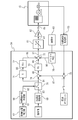
- the radiotherapy apparatus 3 further includes a D / A conversion circuit 61, an amplifier 62, and a thermometer 63 as shown in FIG.
- the D / A conversion circuit 61 generates a control electric signal 64 having a voltage corresponding to the operation amount calculated by the radiation therapy apparatus control apparatus 10.
- the amplifier 62 outputs an amplified electric signal 65 obtained by amplifying the voltage of the control electric signal 64.
- the D / A conversion circuit 61 and the amplifier 62 are arranged on the switchboard.
- the thermometer 63 measures the temperature of the switchboard and outputs the temperature to the radiotherapy device control apparatus 10.
- FIG. 3 further shows the swing position control unit 54.
- the swing position control unit 54 includes a target position correction unit 67, an interpolation command value creation unit 68, an acceleration / deceleration processing unit 69, a switch 70, a differentiation unit 71, a feed forward unit 72, an adder 73, an adder 74, and an operation amount calculation.
- a unit 75, a temperature drift correction unit 76, and an adder 77 are provided.
- the target position correction unit 67 calculates a coefficient based on the time at which the first transmission image and the second transmission image used to calculate the target position calculated by the irradiation target detection unit 52 are taken.
- the target position correction unit 67 calculates a corrected target position 81 based on the target position calculated by the irradiation target detection unit 52 and its coefficient.
- the interpolation command value creation unit 68 calculates an interpolation command value 82 based on the corrected target position 81. At this time, the interpolation command value 82 is calculated every sampling period (for example, 5 ms) that is sufficiently shorter than the measurement period (for example, 50 ms) in which the corrected target position 81 is calculated.
- the acceleration / deceleration processing unit 69 outputs a command value 83 after acceleration / deceleration correction.
- the post-acceleration / deceleration correction command value 83 indicates the position where the isocenter 19 is disposed.
- the switch 70 calculates a command value 84 based on information input to the radiation therapy apparatus control apparatus 10 via the input apparatus.
- the command value 84 indicates one of the interpolation command value 82 and the command value 83 after acceleration / deceleration correction.
- the command value 84 indicates the interpolation command value 82 when tracking is performed, and the command value 83 after acceleration / deceleration correction when tracking is not performed. Is shown.
- the differentiating unit 71 calculates the speed 85 based on the command value 84.
- the speed 85 indicates the amount of change in the command value 84 per unit time.
- the feedforward unit 72 calculates a feedforward manipulated variable 86 based on the speed 85.
- the adder 73 calculates the actual position value 87 based on the position measured by the position integration processing unit 53.
- the actual position value 87 indicates a value obtained by adding the origin offset value to the position measured by the position integration processing unit 53.
- the adder 74 calculates a position deviation 88 based on the command value 84 and the actual position value 87.
- the position deviation 88 indicates a difference obtained by subtracting the actual position value 87 from the command value 84.
- the operation amount calculator 75 calculates an operation amount 89 based on the position deviation 88.
- the temperature drift correction unit 76 calculates a temperature drift correction amount 90 based on the temperature measured by the thermometer 63.
- the adder 77 calculates an operation amount 91 based on the feedforward operation amount 86, the operation amount 89, and the temperature drift correction amount 90.
- the operation amount 91 indicates a sum obtained by adding the feedforward operation amount 86, the operation amount 89, and the temperature drift correction amount 90.
- FIG. 4 shows a change in the coefficient calculated by the target position correction unit 67.
- the change 95 indicates that the period during which the coefficient is calculated is formed from the preparation period 96 and the treatment period 97.
- the preparation period 96 indicates a period before the separation time 98 in the period in which the coefficient is calculated.
- the treatment period 97 indicates a period after the separation time 98 in the period in which the coefficient is calculated.
- the separation time 98 indicates a time when 5000 ms has elapsed from the time when tracking started.
- the change 95 further indicates that 0 is indicated at the time when the tracking starts.
- the change 95 further indicates that the preparation period 96 increases in proportion to the elapsed time.
- the change 95 further indicates a 1 during the treatment period 97.
- the post-correction target position 81 calculated by the target position correction unit 67 indicates the position of a point that internally divides the line segment connecting the target position calculated by the irradiation target detection unit 52 and the isocenter 19.
- the internal ratio at which the position indicated by the post-correction target position 81 internally divides the line segment coincides with the coefficient. That is, the position indicated by the corrected target position 81 indicates the isocenter 19 when the coefficient indicates 0, and indicates the target position calculated by the irradiation target detection unit 52 when the coefficient indicates 1.
- the line segment can be replaced with another line segment that connects another position different from the isocenter 19 and the target position. As another position different from the isocenter 19, a position where the radiation irradiation device 16 is oriented at the start of tracking is exemplified.
- FIG. 5 shows the interpolation command value 82 calculated by the interpolation command value creation unit 68.
- the interpolation command value 82 is formed from a plurality of interpolation command values corresponding to a plurality of times for each sampling period.
- the interpolation command value 101-0 corresponding to the time t0 is equal to the corrected target position calculated by the target position correcting unit 67 at the time before the measurement cycle (50 ms) from the time t0. I'm doing it.
- the interpolation command value 101-1 corresponding to the time t1 is the corrected target position 100 calculated by the target position correction unit 67 at the time t0 before the measurement cycle (50 ms) from the time t1. It matches -1.
- the interpolation command value 101-2 corresponding to the time t2 is set to the corrected target position 100-2 calculated by the target position correction unit 67 at the time t1 that is a measurement cycle before the time t2. Match.
- a plurality of interpolation command values 102-1 corresponding to a period from time t0 to time t1 are interpolated between the interpolation command value 101-0 and the interpolation command value 101-1. Is calculated.
- the plurality of interpolation command values 102-2 corresponding to the period from time t1 to time t2 are interpolated between the interpolation command value 101-1 and the interpolation command value 101-2. Is calculated.
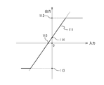
- FIG. 6 shows the relationship between the input and output of the switchboard formed by the D / A conversion circuit 61 and the amplifier 62.
- the relationship 111 indicates that the output is simply increasing with respect to the input, and that the output is generally proportional to the input. Relation 111 further indicates that the output has a maximum value 112 and that the output has a minimum value 113. Relation 111 further indicates that when the input indicates 0, the output indicates a value 114 different from 0, and when the output indicates 0, the input indicates a value 115 different from 0. Yes. Values 114 and 115 vary with the temperature of the switchboard.
- the temperature drift correction unit 76 records in the storage device how the value 115 changes based on the temperature of the switchboard, and based on the switchboard temperature measured by the thermometer 63, the operation amount 89 and When the sum of the feedforward manipulated variable 86 indicates 0, the temperature drift correction amount 90 is calculated so that the voltage of the control electrical signal 64 indicates 0V. That is, the temperature drift correction amount 90 indicates a value obtained by multiplying the value 115 corresponding to the temperature of the switchboard measured by the thermometer 63 by -1.
- the radiotherapy device control apparatus 10 is set when the sum of the operation amount 89 and the feedforward operation amount 86 indicates 0, or when a value equal to or less than a specified value, that is, When it is not necessary to drive the head swing device 15, it can be controlled so as not to drive more reliably.
- FIG. 7 shows the operation amount calculation unit 75.
- the operation amount calculation unit 75 includes an operation amount calculation unit main body 121, a coefficient calculation unit 122, and a multiplier 123.
- the operation amount calculation unit main body 121 calculates the pre-correction operation amount 124 based on the position deviation 88. A well-known calculation is applied to such calculation.
- the coefficient calculation unit 122 calculates the coefficient 125 based on the position deviation 88.
- the multiplier 123 calculates an operation amount 89 that is an output of the operation amount calculation unit 75 based on the pre-correction operation amount 124 and the coefficient 125.
- An operation amount 89 indicates a product obtained by multiplying the operation amount 124 before correction by a coefficient 125.
- FIG. 8 shows the relationship between the position deviation 88 and the coefficient 125.
- the relationship 126 indicates that the coefficient 125 is simply decreased with respect to the absolute value of the position deviation 88.
- the relation 126 further indicates that the coefficient 125 indicates 1 when the absolute value of the position deviation 88 is equal to or less than the value e1.
- the relationship 126 further indicates that the coefficient 125 decreases as the position deviation 88 increases when the absolute value of the position deviation 88 is greater than or equal to the value e1 and less than or equal to the value e2.
- the relationship 126 further indicates that the coefficient 125 indicates the value c1 when the absolute value of the position deviation 88 is greater than or equal to the value e2.
- the value c1 is set so that the driving force generated by the swinging device 15 is larger than the static friction that the radiation irradiation device 16 rotates.
- the radiation therapy apparatus control apparatus 10 can move the therapeutic radiation irradiation apparatus 16 more stably using the head swing device 15.
- the radiotherapy apparatus control apparatus 10 has an operation amount 89 when the position deviation 88 is larger than the existing radiotherapy apparatus control apparatus in which the swing device 15 is controlled based on the pre-correction operation amount 124.
- the radiation irradiation device 16 can be stably rotated using the head swing device 15, and the head swing device 15 can be controlled with higher accuracy.
- the operation method of the radiotherapy apparatus is executed by the radiotherapy apparatus control apparatus 10.
- the user inputs a treatment plan created in advance to the radiation therapy apparatus control apparatus 10 via the input apparatus.
- the treatment plan shows a combination of irradiation angle and dose.
- the irradiation angle indicates the direction in which the therapeutic radiation 23 is applied to the affected area of the patient 43, and indicates the couch position, the O-ring rotation angle, and the gantry rotation angle.
- the couch position indicates the position and orientation of the couch 41 with respect to the foundation.
- the O-ring rotation angle indicates the position of the O-ring 12 with respect to the foundation.
- the gantry rotation angle indicates the position of the traveling gantry 14 with respect to the O-ring 12.
- the dose indicates the dose of the therapeutic radiation 23 irradiated to the patient 43 from each irradiation angle.
- the user fixes the patient 43 to the couch 41 of the radiation therapy apparatus 3.
- the radiation therapy apparatus control apparatus 10 controls the couch driving apparatus 42 so that the couch 41 is disposed at the couch position indicated by the treatment plan.
- the radiation therapy apparatus control device 10 further controls the turning drive device 11 so that the O-ring 12 is arranged at the O-ring rotation angle indicated by the treatment plan.
- the radiotherapy device controller 10 further controls the travel drive device of the radiotherapy device 3 so that the travel gantry 14 is disposed at the gantry rotation angle indicated by the treatment plan.
- the radiotherapy apparatus control apparatus 10 causes the first diagnostic X-ray 35 to be sent to the patient 43 at intervals. Therefore, the first diagnostic X-ray source 24 is controlled so as to be exposed (for example, at intervals of 50 ms).
- the radiotherapy apparatus controller 10 further performs the second diagnosis so that the second diagnostic X-ray 36 is periodically exposed to the patient 43 at a plurality of times when the first diagnostic X-ray 35 is exposed.
- the X-ray source 25 is controlled.
- the radiotherapy device control apparatus 10 further generates a plurality of first transmission images based on the X-rays transmitted through the patient 43 when the first diagnostic X-ray 35 is exposed to the patient 43.
- the first sensor array 32 is controlled.
- the radiotherapy apparatus controller 10 further generates a plurality of second transmission images based on the X-rays transmitted through the patient 43 when the second diagnostic X-ray 36 is exposed to the patient 43.
- the second sensor array 33 is controlled.
- the radiotherapy apparatus controller 10 calculates the specific site position based on the first transmission image and the second transmission image taken at time t0.
- the specific part position indicates the position where the affected part of the patient 43 was placed at time t0.
- the radiotherapy apparatus control apparatus 10 further calculates a target position based on the specific site position.
- the target position indicates a position where the affected part of the patient 43 is disposed at time t1 after 50 ms has elapsed from time t0.
- the radiotherapy device control apparatus 10 calculates the coefficient based on the time t0 so as to coincide with the change 95 in FIG. As shown in FIG. 5, the radiation therapy apparatus control apparatus 10 calculates a corrected target position 100-1 based on the target position and its coefficient.
- the corrected target position 81 indicates the position of a point that internally divides the line segment connecting the target position and the isocenter 19 by the ratio indicated by the coefficient.
- the radiation therapy apparatus control apparatus 10 calculates an interpolation command value 101-1 and a plurality of interpolation command values 102-1 based on the corrected target position 100-1.
- the radiation therapy apparatus control apparatus 10 calculates the feedforward manipulated variable 86 based on the amount of change in the interpolation command value per unit time.
- the radiotherapy apparatus control apparatus 10 calculates the pre-correction operation amount 124 based on the position deviation 88 between the position measured by the head swing apparatus 15 and its interpolation command value.
- the radiotherapy apparatus control apparatus 10 further calculates the coefficient 125 so as to agree with the relation 126 in FIG.
- the radiotherapy device control apparatus 10 calculates an operation amount 89 indicating a product obtained by multiplying the operation amount 124 before correction by the coefficient 125.
- the radiotherapy apparatus controller 10 calculates the temperature drift correction amount 90 based on the temperature measured by the thermometer 63.
- the radiotherapy device control apparatus 10 calculates the operation amount 91 based on the feedforward operation amount 86, the operation amount 89, and the temperature drift correction amount 90.
- the D / A conversion circuit 61 generates a control electric signal 64 having a voltage corresponding to the operation amount 91.
- the amplifier 62 outputs an amplified electric signal 65 obtained by amplifying the voltage of the control electric signal 64.
- the D / A conversion circuit 61 and the amplifier 62 are arranged on the switchboard.
- the head swing device 15 rotates the radiation irradiation device 16 around the pan axis 22 and rotates the radiation irradiation device 16 around the tilt shaft 21 when the amplified electric signal 65 is supplied.
- the radiotherapy apparatus control apparatus 10 controls the therapeutic radiation irradiation apparatus 16 so that the therapeutic radiation 23 is not exposed when the current time is included in the preparation period 96.
- the radiation therapy apparatus control apparatus 10 includes a difference between the position indicated by the interpolation command value and the position where the therapeutic radiation irradiation device 16 faces the current time within a predetermined range.
- the therapeutic radiation irradiation device 16 is controlled so that the therapeutic radiation 23 is exposed to the target.
- the radiotherapy apparatus control device 10 prevents the therapeutic radiation 23 from being exposed when the difference between the interpolation command value and the position where the therapeutic radiation irradiation apparatus 16 faces the current time is not included in the predetermined range.
- the therapeutic radiation irradiation device 16 is controlled.
- the radiation therapy apparatus control apparatus 10 repeatedly controls the therapeutic radiation irradiation apparatus 16 in a sampling period in which the interpolation command value is calculated.
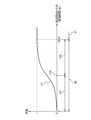
- FIG. 9 shows a change in the target position calculated based on the position where the affected part of the patient 43 was placed.
- the change 131 indicates that the target position is calculated every measurement cycle (50 ms).
- FIG. 9 further shows changes in the corrected target position calculated based on the target position.
- the change 132 indicates that the corrected target position changes gently during the preparation period 96, and the corrected target position matches the target position during the treatment period 97.
- FIG. 9 further shows changes in the interpolation command value calculated based on the corrected target position.
- the change 133 indicates that the interpolation command value is calculated at a cycle shorter than the measurement cycle (50 ms) at which the target position is calculated.
- the change 133 further indicates that the interpolation command value gradually changes during the preparation period 96.
- the change 133 further indicates that the target position matches the interpolation command value in the treatment period 97.
- the radiotherapy apparatus controller 10 is configured such that when the therapeutic radiation irradiation apparatus 16 is initially facing the isocenter 19, the therapeutic radiation irradiation apparatus 16 is in the preparation period 96. It is not controlled to move rapidly. For this reason, even if the radiotherapy apparatus control apparatus 10 is in a state where the response is improved by increasing the control gain, the motor swing of the swinging apparatus 15 during the preparation period 96 is prevented.
- the operation amount 89 does not become too large when the position deviation 88 is large. For this reason, when the positional deviation 88 is large, the radiation therapy apparatus control apparatus 10 can move the radiation irradiation apparatus 16 more stably using the head swing device 15. For this reason, the radiation therapy apparatus control device 10 stabilizes the radiation irradiation apparatus 16 using the head swing device 15 as compared with a known existing radiation therapy apparatus control device that does not include the coefficient calculation unit 122 and the multiplier 123.
- the swinging device 15 can be controlled with higher accuracy.
- the radiotherapy apparatus control apparatus 10 further calculates the temperature drift correction amount 90 based on the temperature of the switchboard measured by the thermometer 63. According to such a temperature drift correction amount 90, the radiotherapy apparatus control apparatus 10 can perform control so as not to drive the swinging apparatus 15 more reliably when it is not necessary to drive the swinging apparatus 15.
- the coefficient calculated by the target position correcting unit 67 can be replaced with a change different from the change 95 in the above-described form.
- the coefficient only needs to indicate 0 at the time when the tracking starts, simply increase with respect to the elapsed time in the preparation period 96, and indicate 1 in the treatment period 97.
- FIG. 10 shows an example of the change.
- the change 141 indicates that the preparation period 96 is formed of the first period 142 and the second period 143.
- the first period 142 indicates a period before the separation time 144 in the preparation period 96.
- the second period 143 indicates a period after the separation time 144 in the preparation period 96.
- the separation time 144 is an arbitrary time that belongs to the preparation period 96.
- a change 141 indicates that 0 is indicated at the time when the tracking starts.
- the change 141 further indicates that the first period 142 simply increases convexly downward.
- the change 141 further indicates that the second period 143 simply increases convexly upward.
- the change 141 further indicates that the treatment period 97 indicates 1. Even when such a change 141 is applied, the radiation therapy apparatus control apparatus 10 increases the responsiveness by increasing the control gain in the preparation period 96 in the same manner as in the above-described embodiment. It is possible to prevent the motor swing of the head swing device 15.
- the radiotherapy apparatus control apparatus 10 can also calculate the target position based on the specific part position calculated based on another sensor different from the imager system of the radiotherapy apparatus 3.
- An infrared camera is exemplified as the sensor.
- the radiotherapy device control apparatus 10 calculates the position of the affected part of the patient 43 based on the position at which the marker placed on the body surface of the patient 43 is displayed in the infrared image captured by the infrared camera, and the position Based on, the target position is calculated. Even when such a sensor is applied, the radiation therapy apparatus control apparatus 10 starts the preparation period 96 in a state in which responsiveness is improved by increasing the control gain in the same manner as in the above-described embodiment. It is possible to prevent the swing device 15 from tripping the motor.
Abstract
本発明による放射線治療装置制御装置は、被検体の内部の特定部位が配置される特定部位位置に基づいて目標位置を算出する照射対象検出部と、治療用放射線を曝射する放射線照射装置が補正後目標位置に向くように、その放射線照射装置を移動させる駆動装置を制御する首振り位置制御部とを備えている。その補正後目標位置は、治療期間の前の準備期間に、その目標位置よりその放射線照射装置が向いている位置に近い位置を示し、その治療期間に、その目標位置を示している。
Description
本発明は、放射線治療装置制御装置および放射線治療装置の作動方法に関し、特に、患部に放射線を照射することにより患者を治療するときに利用される放射線治療装置制御装置および放射線治療装置の作動方法に関する。
腫瘍患部に治療用放射線を曝射することにより患者を治療する放射線治療が知られている。その放射線治療を実行する放射線治療装置は、その治療用放射線を曝射する治療用放射線照射装置と、その患者の患部の位置を測定するセンサと、その測定された位置にその治療用放射線が照射されるようにその治療用放射線照射装置を移動させる駆動装置とを備えている。このような放射線治療装置によれば、その患者の呼吸等に伴ってその患部が動く場合でも、その患部に治療用放射線を照射することができる。このような放射線治療は、治療効果が高いことが望まれ、その治療用放射線は、その患部の細胞に曝射される線量に比較して、正常な細胞に曝射される線量がより小さいことが望まれている。このため、その放射線治療装置は、その治療用放射線をより高精度にその患部に曝射することが望まれ、その治療用放射線照射装置をより高精度に移動させることが望まれている。その放射線治療装置は、さらに、その駆動装置の応答性が高いことが望まれ、かつ、その駆動装置の動作が安定していることが望まれている。
特開2004-65808号公報には、照射野を広い照射野から微細な不整形照射野まで形成し、照射時間の短縮と患者の体動に対しても適切に照射でき、かつ小型化が可能な放射線治療装置が開示されている。その放射線治療装置は、電子線の発生源と、前記電子線の方向を変える偏向電磁石と、真空を保持しながら前記電子線を通過させる真空窓と、前記電子線を散乱させる散乱箔と、前記電子線をX線に変換するターゲットと、電子線とX線の線量分布を照射面において一様にする平坦化フィルタと、電子線とX線を絞り込むコリメータと、電子線とX線の線量を測定する線量計から構成される照射ヘッドと、前記照射ヘッドを保持するガントリーアームを含む放射線治療装置であって、前記電子線の発生源と前記偏向電磁石とを真空ロータリージョイントで結合し、前記ガントリーアーム回転軸と平行で仮想線源位置を通る軸を中心として前記照射ヘッドを首振り運動させる回転手段を備えている。
特開2006-21046号公報には、放射線の照射治療中においても、リアルタイムに治療野の状態をモニタすることが可能な放射線治療装置が開示されている。その放射線治療装置は、O型ガントリと、前記O型ガントリに移動可能に設けられ、被検体の治療野へ治療用放射線を照射する放射線照射ヘッドと、前記O型ガントリに移動可能に設けられ、前記被検体の前記治療野に診断用X線を照射するX線源と、前記O型ガントリに移動可能に設けられ、前記被検体を透過した前記診断用X線の透過X線を検出して、診断画像データとして出力するセンサアレイとを具備し、前記センサアレイは、前記放射線照射ヘッドを挟んで対象な位置に設けられ、前記O型ガントリ上を前記放射線照射ヘッドの移動に連動して動き、前記X線源は、前記センサアレイの動きに連動して動く。
本発明の課題は、治療用放射線を曝射する放射線照射装置を移動させる駆動装置のモータトリップを防止し、かつ、その放射線照射装置を高精度に移動させる放射線治療装置制御装置および放射線治療装置の作動方法を提供することにある。
本発明による放射線治療装置制御装置は、被検体の内部の特定部位が測定時刻に配置される特定部位位置に基づいて目標位置を算出する照射対象検出部と、治療用放射線を曝射する放射線照射装置がその測定時刻より後の制御時刻に補正後目標位置に向くように、その放射線照射装置を移動させる駆動装置を制御する首振り位置制御部とを備えている。その補正後目標位置は、その制御時刻が準備期間に含まれるときに、その目標位置より、その制御時刻の直前にその放射線照射装置が向いている位置に近い位置を示している。その補正後目標位置は、その制御時刻がその準備期間の後の治療期間に含まれるときに、その目標位置を示している。このような放射線治療装置制御装置は、その放射線照射装置が緩やかに移動するようにその駆動装置を制御した後にその放射線照射装置がその特定部位を追尾するようにその駆動装置を制御することにより、その駆動装置のモータトリップを防止し、かつ、その放射線照射装置を高精度に移動させることができる。
その補正後目標位置は、その制御時刻がその準備期間に含まれるときに、初期位置とその目標位置と結ぶ線分を内分する位置を示している。このとき、その補正後目標位置がその線分を内分する内分比は、時間の経過とともにその補正後目標位置がその目標位置に漸近するように算出されることが好ましい。
その内分比が単位時間当たりに変化する変化量は、一定であることが好ましい。
その首振り位置制御部は、その補正後目標位置とその放射線照射装置が向いている位置との位置偏差に基づいて操作量を算出する操作量算出部と、その位置偏差に基づいて係数を算出する係数演算部と、その操作量にその係数を乗算して補正後操作量を算出する乗算器とを備えている。その係数は、その位置偏差の絶対値に関して単純に減少する。その駆動装置は、その補正後操作量に基づいて制御されることが好ましい。
その首振り位置制御部は、その補正後目標位置の変化に基づいてフィードフォワード操作量を算出するフィードフォワード部をさらに備えている。このとき、その駆動装置は、そのフィードフォワード操作量にさらに基づいて制御されることが好ましい。
その首振り位置制御部は、その駆動装置が制御されるときにその駆動装置に供給される電気信号を生成する装置の温度に基づいて温度ドリフト量を算出する温度ドリフト補正部をさらに備えている。その駆動装置は、その温度ドリフト量にさらに基づいて制御されることが好ましい。
本発明による放射線治療装置の作動方法は、被検体の内部の特定部位が測定時刻に配置される特定部位位置に基づいて目標位置を算出するステップと、治療用放射線を曝射する放射線照射装置がその測定時刻より後の制御時刻に補正後目標位置に向くように、その放射線照射装置を移動させる駆動装置を制御するステップとを備えている。その補正後目標位置は、その制御時刻が準備期間に含まれるときに、その目標位置より、その制御時刻の直前にその放射線照射装置が向いている位置に近い位置を示している。その制御時刻がその準備期間の後の治療期間に含まれるときに、その目標位置を示している。このような放射線治療装置の作動方法によれば、放射線治療装置制御装置は、その放射線照射装置が緩やかに移動するようにその駆動装置を制御した後にその放射線照射装置がその特定部位を追尾するようにその駆動装置を制御することにより、その駆動装置のモータトリップを防止し、かつ、その放射線照射装置を高精度に移動させることができる。
その補正後目標位置は、その制御時刻がその準備期間に含まれるときに、初期位置とその目標位置と結ぶ線分を内分する位置を示している。その補正後目標位置がその線分を内分する内分比は、時間の経過とともにその補正後目標位置がその目標位置に漸近するように算出される。
その内分比が単位時間当たりに変化する変化量は、一定であることが好ましい。
本発明による放射線治療装置の作動方法は、その補正後目標位置とその放射線照射装置が向いている位置との位置偏差に基づいて操作量を算出するステップと、その位置偏差に基づいて係数を算出するステップと、その操作量にその係数を乗算して補正後操作量を算出するステップとをさらに備えている。その係数は、その位置偏差の絶対値に関して単純に減少する。その駆動装置は、その補正後操作量に基づいて制御されることが好ましい。
本発明による放射線治療装置の作動方法は、その補正後目標位置の変化に基づいてフィードフォワード操作量を算出するステップをさらに備えている。このとき、その駆動装置は、そのフィードフォワード操作量にさらに基づいて制御されることが好ましい。
本発明による放射線治療装置の作動方法は、その駆動装置が制御されるときにその駆動装置に供給される電気信号を生成する装置の温度に基づいて温度ドリフト量を算出するステップをさらに備えている。このとき、その駆動装置は、その温度ドリフト量にさらに基づいて制御されることが好ましい。
本発明による放射線治療装置制御装置および放射線治療装置の作動方法は、治療用放射線を曝射する放射線照射装置を移動させるときに、その放射線照射装置を移動させる駆動装置のモータトリップを防止し、かつ、その放射線照射装置を高精度に移動させることができる。
図面を参照して、本発明による放射線治療装置制御装置の実施の形態を記載する。その放射線治療装置制御装置10は、図1に示されているように、放射線治療システムに適用されている。その放射線治療システムは、放射線治療装置制御装置10と放射線治療装置3とを備えている。放射線治療装置制御装置10は、パーソナルコンピュータに例示されるコンピュータである。放射線治療装置制御装置10と放射線治療装置3とは、双方向に情報を伝送することができるように、互いに接続されている。
放射線治療装置3は、Oリング12と走行ガントリ14と治療用放射線照射装置16とを備えている。Oリング12は、リング状に形成され、回転軸17を中心に回転可能に基礎に支持されている。回転軸17は、鉛直方向に平行である。走行ガントリ14は、リング状に形成され、Oリング12のリングの内側に配置され、回転軸18を中心に回転可能にOリング12に支持されている。回転軸18は、鉛直方向に垂直であり、回転軸17に含まれるアイソセンタ19を通っている。回転軸18は、Oリング12に対して固定され、すなわち、Oリング12とともに回転軸17を中心に回転する。
治療用放射線照射装置16は、走行ガントリ14のリングの内側に配置されている。治療用放射線照射装置16は、チルト軸21に回転可能に、かつ、パン軸22に回転可能に、走行ガントリ14に支持されている。パン軸22は、走行ガントリ14に対して固定され、回転軸18に交差しないで回転軸18に平行である。チルト軸21は、パン軸22に直交している。チルト軸21とパン軸22との交点は、アイソセンタ19から1mだけ離れている。
放射線治療装置3は、さらに、旋回駆動装置11と首振り装置15とを備え、図示されていない走行駆動装置を備えている。旋回駆動装置11は、放射線治療装置制御装置10により制御されることにより、回転軸17を中心にOリング12を回転させる。旋回駆動装置11は、さらに、基礎に対してOリング12が配置される旋回角度を測定し、その旋回角度を放射線治療装置制御装置10に出力する。その走行駆動装置は、放射線治療装置制御装置10により制御されることにより、回転軸18を中心に走行ガントリ14を回転させる。その走行駆動装置は、さらに、Oリング12に対して走行ガントリ14が配置されるガントリ角度を測定し、そのガントリ角度を放射線治療装置制御装置10に出力する。
首振り装置15は、放射線治療装置制御装置10により制御されることにより、チルト軸21を中心に治療用放射線照射装置16を回転させ、パン軸22を中心に治療用放射線照射装置16を回転させる。首振り装置15は、さらに、チルト軸21を中心に走行ガントリ14に対して治療用放射線照射装置16が回転するチルト角を測定し、そのチルト角を放射線治療装置制御装置10に出力する。首振り装置15は、さらに、パン軸22を中心に走行ガントリ14に対して治療用放射線照射装置16が回転するパン角を測定し、そのパン角を放射線治療装置制御装置10に出力する。
治療用放射線照射装置16は、放射線治療装置制御装置10により制御されることにより、治療用放射線23を曝射する。治療用放射線23は、パン軸22とチルト軸21とが交差する交点を頂点とするコーンビームである。治療用放射線23は、一様強度分布を持つように形成されている。治療用放射線照射装置16は、マルチリーフコリメータ20を備えている。マルチリーフコリメータ20は、治療用放射線23が進行する領域に配置されるように、治療用放射線照射装置16に固定されている。マルチリーフコリメータ20は、放射線治療装置制御装置10により制御されることにより、治療用放射線23の一部を遮蔽し、治療用放射線23が患者に照射されるときの照射野の形状を変更する。
治療用放射線23は、このように治療用放射線照射装置16が走行ガントリ14に支持されることにより、治療用放射線照射装置16がアイソセンタ19に向かうように走行ガントリ14に固定されると、旋回駆動装置11によりOリング12が回転し、または、その走行駆動装置により走行ガントリ14が回転しても、常に概ねアイソセンタ19を通る。即ち、走行・旋回を行うことで任意方向からアイソセンタ19に向けて治療用放射線23の照射が可能になる。
放射線治療装置3は、さらに、複数のイメージャシステムを備えている。すなわち、放射線治療装置3は、第1診断用X線源24と第2診断用X線源25と第1センサアレイ32と第2センサアレイ33とを備えている。第1診断用X線源24は、走行ガントリ14に支持され、アイソセンタ19から第1診断用X線源24を結ぶ線分とアイソセンタ19から治療用放射線照射装置16を結ぶ線分とのなす角が鋭角になるように、走行ガントリ14のリングの内側に配置されている。第2診断用X線源25は、走行ガントリ14に支持され、アイソセンタ19から第2診断用X線源25を結ぶ線分とアイソセンタ19から治療用放射線照射装置16を結ぶ線分とのなす角が鋭角になるように、走行ガントリ14のリングの内側に配置されている。第2診断用X線源25は、さらに、アイソセンタ19から第1診断用X線源24を結ぶ線分とアイソセンタ19から第2診断用X線源25を結ぶ線分とのなす角が直角(90度)になるように、配置されている。第1センサアレイ32は、走行ガントリ14に支持され、アイソセンタ19を介して第1診断用X線源24に対向するように、配置されている。第2センサアレイ33は、走行ガントリ14に支持され、アイソセンタ19を介して第2診断用X線源25に対向するように、配置されている。
第1診断用X線源24は、放射線治療装置制御装置10により制御されることにより、所定のタイミングで第1診断用X線35をアイソセンタ19に向けて曝射する。第1診断用X線35は、第1診断用X線源24が有する1点から曝射され、その1点を頂点とする円錐状のコーンビームである。第2診断用X線源25は、放射線治療装置制御装置10により制御されることにより、所定のタイミングで第2診断用X線36をアイソセンタ19に向けて曝射する。第2診断用X線36は、第2診断用X線源25が有する1点から曝射され、その1点を頂点とする円錐状のコーンビームである。
第1センサアレイ32は、受光部を備えている。第1センサアレイ32は、放射線治療装置制御装置10により制御されることにより、その受光部に受光されるX線に基づいて第1透視画像を生成する。第2センサアレイ33は、受光部を備えている。第2センサアレイ33は、放射線治療装置制御装置10により制御されることにより、その受光部に受光されるX線に基づいて第2透視画像を生成する。その透視画像は、複数の画素から形成されている。その複数の画素は、その透視画像上にマトリクス状に配置され、それぞれ輝度に対応付けられている。その透視画像は、その複数の画素の各々に対応する輝度がその複数の画素の各々に着色されることにより、被写体を映し出している。第1センサアレイ32と第2センサアレイ33としては、FPD(Flat Panel Detector)、X線II(Image Intensifier)が例示される。
このようなイメージャシステムによれば、第1センサアレイ32と第2センサアレイ33とにより得た画像信号に基づき、アイソセンタ19を中心とする透視画像を生成することができる。
放射線治療装置3は、さらに、カウチ41とカウチ駆動装置42とを備えている。カウチ41は、x軸とy軸とz軸とを中心に回転移動可能に、かつ、そのx軸とy軸とz軸とに平行に平行移動可能に基礎に支持されている。そのx軸とy軸とz軸とは、互いに直交している。カウチ41は、その放射線治療システムにより治療される患者43が横臥することに利用される。カウチ41は、図示されていない固定具を備えている。その固定具は、患者43が動かないように、患者43をカウチ41に固定する。カウチ駆動装置42は、放射線治療装置制御装置10により制御されることにより、カウチ41を回転移動させ、カウチ41を平行移動させる。
図2は、放射線治療装置制御装置10を示している。その放射線治療装置制御装置10は、コンピュータであり、図示されていないCPUと記憶装置とリムーバルメモリドライブと通信装置と入力装置と出力装置とインターフェースとを備えている。そのCPUは、放射線治療装置制御装置10にインストールされるコンピュータプログラムを実行して、その記憶装置と入力装置と出力装置とを制御する。その記憶装置は、そのコンピュータプログラムを記録し、そのCPUに利用される情報を記録し、そのCPUにより生成される情報を記録する。そのリムーバルメモリドライブは、記録媒体が挿入されたときに、その記録媒体に記録されているデータを読み出すことに利用される。そのリムーバルメモリドライブは、特に、コンピュータプログラムが記録されている記録媒体が挿入されたときに、そのコンピュータプログラムを放射線治療装置制御装置10にインストールするときに利用される。その通信装置は、通信回線網を介して接続される他のコンピュータから配信される情報を放射線治療装置制御装置10にダウンロードする。その通信装置は、特に、他のコンピュータからコンピュータプログラムを放射線治療装置制御装置10にダウンロードし、そのコンピュータプログラムを放射線治療装置制御装置10にインストールするときに利用される。その入力装置は、ユーザに操作されることにより生成される情報をそのCPUに出力する。その入力装置としては、キーボード、マウスが例示される。その出力装置は、そのCPUにより生成された情報をユーザに認識可能に出力する。その出力装置としては、そのCPUにより生成された画像を表示するディスプレイが例示される。
そのインターフェースは、放射線治療装置制御装置10に接続される外部機器により生成される情報をそのCPUに出力し、そのCPUにより生成された情報をその外部機器に出力する。その外部機器は、放射線治療装置3の旋回駆動装置11と走行駆動装置と首振り装置15と治療用放射線照射装置16とマルチリーフコリメータ20と第1診断用X線源24と第2診断用X線源25と第1センサアレイ32と第2センサアレイ33とカウチ駆動装置42とを含んでいる。
放射線治療装置制御装置10にインストールされるコンピュータプログラムは、放射線治療装置制御装置10に複数の機能をそれぞれ実現させるための複数のコンピュータプログラムから形成されている。その複数の機能は、治療計画収集部51と照射対象検出部52と位置積算処理部53と首振り位置制御部54と照射部55とを含んでいる。
治療計画収集部51は、入力装置から治療計画を収集する。その治療計画は、照射角度と線量との組み合わせを示している。その照射角度は、患者43の患部に治療用放射線23を照射する方向を示し、カウチ位置とOリング回転角とガントリ回転角とを示している。そのカウチ位置は、基礎に対するカウチ41の位置を示している。そのOリング回転角は、基礎に対するOリング12の位置を示している。そのガントリ回転角は、Oリング12に対する走行ガントリ14の位置を示している。その線量は、その照射角度から患者43に照射される治療用放射線23の線量を示している。
照射対象検出部52は、その治療計画が示すカウチ位置にカウチ41が配置されるように、すなわち、患者43の患部が概ねアイソセンタ19に配置されるように、カウチ駆動装置42を制御する。照射対象検出部52は、さらに、その治療計画が示すOリング回転角にOリング12が配置されるように、旋回駆動装置11を制御する。照射対象検出部52は、さらに、その治療計画が示すガントリ回転角に走行ガントリ14が配置されるように、放射線治療装置3の走行駆動装置を制御する。
照射対象検出部52は、その治療計画が示す所定の位置にカウチ41とOリング12と走行ガントリ14とが所定の位置に配置された後に、第1診断用X線35が患者43に周期的に(たとえば、50ms間隔で)曝射されるように、第1診断用X線源24を制御する。照射対象検出部52は、さらに、第1診断用X線35が曝射される複数の時刻に第2診断用X線36が患者43に周期的に曝射されるように、第2診断用X線源25を制御する。照射対象検出部52は、さらに、第1診断用X線35が患者43に曝射されたときに、患者43を透過したX線に基づいて複数の第1透過画像が生成されるように、第1センサアレイ32を制御する。照射対象検出部52は、さらに、第2診断用X線36が患者43に曝射されたときに、患者43を透過したX線に基づいて複数の第2透過画像が生成されるように、第2センサアレイ33を制御する。
照射対象検出部52は、その複数の第1透過画像と複数の第2透過画像とに基づいて複数の特定部位位置を算出する。その複数の特定部位位置は、第1診断用X線35(第2診断用X線36)が曝射される複数の時刻に患者43の患部が配置されていた位置をそれぞれ示している。すなわち、照射対象検出部52は、その第1透過画像と第2透過画像が撮影されるごとに、その第1透過画像と第2透過画像とに基づいて患者43の患部が配置されている特定部位位置を算出する。
照射対象検出部52は、さらに、その特定部位位置に基づいて目標位置を算出する。その目標位置は、その第1透過画像と第2透過画像が撮影された時刻から50msだけ経過した時刻に患者43の患部が配置されている位置を示している。
位置積算処理部53は、治療用放射線照射装置16が現在時刻に向いている位置を測定するように、首振り装置15を制御する。その位置は、治療用放射線照射装置16のチルト角とパン角とから形成されている。すなわち、位置積算処理部53は、治療用放射線照射装置16のチルト角とパン角とを測定するように、首振り装置15を制御し、そのチルト角とパン角とに基づいて治療用放射線照射装置16が現在時刻に向いている位置を算出する。
首振り位置制御部54は、照射対象検出部52により算出された目標位置に基づいて、操作量を算出する。首振り装置15は、その操作量に基づいて、治療用放射線照射装置16をパン軸22またはチルト軸21を中心に回転移動させる。このとき、首振り位置制御部54は、照射対象検出部52により複数の第1透過画像が撮影される測定周期に比較して十分に短いサンプリング周期(たとえば、5ms)でその操作量を算出する。
照射部55は、首振り位置制御部54により治療用放射線照射装置16が向けられようとしている位置と治療用放射線照射装置16が実際に向いている位置との差が所定範囲に含まれるときに、治療用放射線23が曝射されるように、治療用放射線照射装置16を制御する。
放射線治療装置3は、さらに、図3に示されているように、D/A変換回路61とアンプ62と温度計63とを備えている。D/A変換回路61は、放射線治療装置制御装置10により算出された操作量に対応する電圧の制御電気信号64を生成する。アンプ62は、制御電気信号64の電圧を増幅した増幅後電気信号65を出力する。D/A変換回路61とアンプ62とは、配電盤に配置されている。温度計63は、その配電盤の温度を測定し、その温度を放射線治療装置制御装置10に出力する。
図3は、さらに、首振り位置制御部54を示している。首振り位置制御部54は、目標位置補正部67と補間指令値作成部68と加減速処理部69とスイッチ70と微分部71とフィードフォワード部72と加算器73と加算器74と操作量算出部75と温度ドリフト補正部76と加算器77とを備えている。
目標位置補正部67は、照射対象検出部52により算出された目標位置を算出するために用いられた第1透過画像と第2透過画像とが撮影された時刻に基づいて係数を算出する。目標位置補正部67は、照射対象検出部52により算出された目標位置とその係数とに基づいて補正後目標位置81を算出する。補間指令値作成部68は、補正後目標位置81に基づいて補間指令値82を算出する。このとき、補間指令値82は、補正後目標位置81が算出される測定周期(たとえば、50ms)に比較して十分に短いサンプリング周期(たとえば、5ms)毎に算出される。
加減速処理部69は、加減速補正後指令値83を出力する。加減速補正後指令値83は、アイソセンタ19が配置された位置を示している。
スイッチ70は、入力装置を介して放射線治療装置制御装置10に入力される情報に基づいて指令値84を算出する。指令値84は、補間指令値82と加減速補正後指令値83とのうちの一方を示し、追尾を行うときに補間指令値82を示し、追尾を行わないときに加減速補正後指令値83を示している。
微分部71は、指令値84に基づいて速度85を算出する。速度85は、指令値84が単位時間当たりに変化した変化量を示している。フィードフォワード部72は、速度85に基づいてフィードフォワード操作量86を算出する。
加算器73は、位置積算処理部53により測定される位置に基づいて位置実績値87を算出する。位置実績値87は、位置積算処理部53により測定される位置に原点オフセット値が加算された値を示している。加算器74は、指令値84と位置実績値87とに基づいて位置偏差88を算出する。位置偏差88は、指令値84から位置実績値87を減算した差を示している。
操作量算出部75は、位置偏差88に基づいて操作量89を算出する。温度ドリフト補正部76は、温度計63により測定された温度に基づいて温度ドリフト補正量90を算出する。加算器77は、フィードフォワード操作量86と操作量89と温度ドリフト補正量90とに基づいて操作量91を算出する。操作量91は、フィードフォワード操作量86と操作量89と温度ドリフト補正量90とを加算した和を示している。
図4は、目標位置補正部67により算出される係数の変化を示している。その変化95は、その係数が算出される期間が準備期間96と治療期間97とから形成されていることを示している。準備期間96は、その係数が算出される期間のうちの分離時刻98より前の期間を示している。治療期間97は、その係数が算出される期間のうちの分離時刻98より後の期間を示している。分離時刻98は、追尾が開始した時刻から5000msだけ経過した時刻を示している。変化95は、さらに、その追尾が開始した時刻に0を示すことを示している。変化95は、さらに、準備期間96で、その経過時間に比例するように増加することを示している。変化95は、さらに、治療期間97で、1を示すことを示している。
このとき、目標位置補正部67により算出される補正後目標位置81は、照射対象検出部52により算出された目標位置とアイソセンタ19とを結ぶ線分を内分する点の位置を示している。補正後目標位置81が示す位置がその線分を内分する内分比は、その係数に一致している。すなわち、補正後目標位置81が示す位置は、その係数が0を示すときにアイソセンタ19を示し、その係数が1を示すときに照射対象検出部52により算出された目標位置を示している。なお、その線分は、アイソセンタ19と異なる他の位置と目標位置とを結ぶ他の線分に置換することができる。アイソセンタ19と異なる他の位置としては、放射線照射装置16が追尾開始時に向いていた位置が例示される。
図5は、補間指令値作成部68により算出される補間指令値82を示している。補間指令値82は、サンプリング周期ごとの複数の時刻に対応する複数の補間指令値から形成されている。その複数の補間指令値のうちの時刻t0に対応する補間指令値101-0は、時刻t0より測定周期(50ms)だけ前の時刻に目標位置補正部67により算出された補正後目標位置に一致している。その複数の補間指令値のうちの時刻t1に対応する補間指令値101-1は、時刻t1より測定周期(50ms)だけ前の時刻t0に目標位置補正部67により算出された補正後目標位置100-1に一致している。その複数の補間指令値のうちの時刻t2に対応する補間指令値101-2は、時刻t2より測定周期だけ前の時刻t1に目標位置補正部67により算出された補正後目標位置100-2に一致している。
その複数の補間指令値のうちの時刻t0から時刻t1までの期間に対応する複数の補間指令値102-1は、補間指令値101-0と補間指令値101-1とを内挿するように、算出される。その複数の補間指令値のうちの時刻t1から時刻t2までの期間に対応する複数の補間指令値102-2は、補間指令値101-1と補間指令値101-2とを内挿するように、算出される。
図6は、D/A変換回路61とアンプ62とから形成される配電盤の入力と出力の関係を示している。その関係111は、その入力に関してその出力が単純に増加していることを示し、その出力がその入力に概ね比例していることを示している。関係111は、さらに、その出力が最大値112を有していることを示し、その出力が最小値113を有していることを示している。関係111は、さらに、その入力が0を示すときにその出力が0と異なる値114を示すことを示し、その出力が0を示すときにその入力が0と異なる値115を示すことを示している。値114と値115とは、その配電盤の温度により変化する。
このとき、温度ドリフト補正部76は、配電盤の温度に基づいて値115がどのように変化するかを記憶装置に記録し、温度計63により測定された配電盤の温度に基づいて、操作量89とフィードフォワード操作量86との和が0と示すときに、制御電気信号64の電圧が0Vを示すように、温度ドリフト補正量90を算出する。すなわち、温度ドリフト補正量90は、温度計63により測定された配電盤の温度に対応する値115に-1を乗算した値を示している。このような制御によれば、放射線治療装置制御装置10は、操作量89とフィードフォワード操作量86との和が0を示すときに、または指定したある値以下の値を示すときに、すなわち、首振り装置15を駆動する必要がないときに、より確実に駆動させないように制御することができる。
図7は、操作量算出部75を示している。操作量算出部75は、操作量算出部本体121と係数演算部122と乗算器123とを備えている。操作量算出部本体121は、位置偏差88に基づいて補正前操作量124を算出する。このような算出は、周知のものが適用される。係数演算部122は、位置偏差88に基づいて係数125を算出する。乗算器123は、補正前操作量124と係数125とに基づいて操作量算出部75の出力である操作量89を算出する。操作量89は、補正前操作量124に係数125を乗算した積を示している。
図8は、位置偏差88と係数125との関係を示している。その関係126は、位置偏差88の絶対値に関して、係数125が単純に減少していることを示している。関係126は、さらに、位置偏差88の絶対値が値e1以下であるときに、係数125が1を示すことを示している。関係126は、さらに、位置偏差88の絶対値が値e1以上であり、かつ、値e2以下であるときに、係数125が、位置偏差88の増加と共に、減少していることを示している。関係126は、さらに、位置偏差88の絶対値が値e2以上であるときに、係数125が値c1を示すことを示している。値c1は、首振り装置15により生成される駆動力が、放射線照射装置16が回転する静止摩擦より大きくなるように、設定される。
このような係数125によれば、位置偏差88が大きいときに、操作量89が大きくなり過ぎない。このため、放射線治療装置制御装置10は、位置偏差88が大きいときに、首振り装置15を用いて治療用放射線照射装置16をより安定して移動させることができる。このため、放射線治療装置制御装置10は、首振り装置15が補正前操作量124に基づいて制御される既存の放射線治療装置制御装置に比較して、位置偏差88が大きいときに、操作量89を小さくすることができ、首振り装置15を用いて放射線照射装置16を安定して回転させることができ、首振り装置15をより高精度に制御することができる。
本発明による放射線治療装置の作動方法は、放射線治療装置制御装置10により実行される。ユーザは、まず、入力装置を介して、事前に作成された治療計画を放射線治療装置制御装置10に入力する。その治療計画は、照射角度と線量との組み合わせを示している。その照射角度は、患者43の患部に治療用放射線23を照射する方向を示し、カウチ位置とOリング回転角とガントリ回転角とを示している。そのカウチ位置は、基礎に対するカウチ41の位置と向きとを示している。そのOリング回転角は、基礎に対するOリング12の位置を示している。そのガントリ回転角は、Oリング12に対する走行ガントリ14の位置を示している。その線量は、その各照射角度から患者43に照射される治療用放射線23の線量を示している。
ユーザは、放射線治療装置3のカウチ41に患者43を固定する。放射線治療装置制御装置10は、その治療計画が示すカウチ位置にカウチ41が配置されるように、カウチ駆動装置42を制御する。放射線治療装置制御装置10は、さらに、その治療計画が示すOリング回転角にOリング12が配置されるように、旋回駆動装置11を制御する。放射線治療装置制御装置10は、さらに、その治療計画が示すガントリ回転角に走行ガントリ14が配置されるように、放射線治療装置3の走行駆動装置を制御する。
放射線治療装置制御装置10は、その治療計画が示す所定の位置にカウチ41とOリング12と走行ガントリ14とが所定の位置に配置された後に、第1診断用X線35が患者43に周期的に(たとえば、50ms間隔で)曝射されるように、第1診断用X線源24を制御する。放射線治療装置制御装置10は、さらに、第1診断用X線35が曝射される複数の時刻に第2診断用X線36が患者43に周期的に曝射されるように、第2診断用X線源25を制御する。放射線治療装置制御装置10は、さらに、第1診断用X線35が患者43に曝射されたときに、患者43を透過したX線に基づいて複数の第1透過画像が生成されるように、第1センサアレイ32を制御する。放射線治療装置制御装置10は、さらに、第2診断用X線36が患者43に曝射されたときに、患者43を透過したX線に基づいて複数の第2透過画像が生成されるように、第2センサアレイ33を制御する。
放射線治療装置制御装置10は、時刻t0に撮影された第1透過画像と第2透過画像とに基づいて特定部位位置を算出する。その特定部位位置は、時刻t0に患者43の患部が配置されていた位置を示している。放射線治療装置制御装置10は、さらに、その特定部位位置に基づいて目標位置を算出する。その目標位置は、時刻t0から50msだけ経過した時刻t1に患者43の患部が配置されている位置を示している。放射線治療装置制御装置10は、図4の変化95に一致するように、時刻t0に基づいて係数を算出する。放射線治療装置制御装置10は、図5に示されているように、その目標位置とその係数とに基づいて補正後目標位置100-1を算出する。補正後目標位置81は、その目標位置とアイソセンタ19とを結ぶ線分を、その係数が示す比で内分する点の位置を示している。放射線治療装置制御装置10は、補正後目標位置100-1に基づいて補間指令値101-1と複数の補間指令値102-1とを算出する。
放射線治療装置制御装置10は、その補間指令値が単位時間当たりに変化した変化量に基づいてフィードフォワード操作量86を算出する。
放射線治療装置制御装置10は、首振り装置15により測定される位置とその補間指令値との位置偏差88に基づいて補正前操作量124を算出する。放射線治療装置制御装置10は、さらに、図8の関係126に一致するように、係数125を算出する。放射線治療装置制御装置10は、補正前操作量124に係数125を乗算した積を示す操作量89を算出する。
放射線治療装置制御装置10は、温度計63により測定された温度に基づいて温度ドリフト補正量90を算出する。
放射線治療装置制御装置10は、フィードフォワード操作量86と操作量89と温度ドリフト補正量90とに基づいて操作量91を算出する。D/A変換回路61は、操作量91に対応する電圧の制御電気信号64を生成する。アンプ62は、制御電気信号64の電圧を増幅した増幅後電気信号65を出力する。D/A変換回路61とアンプ62とは、配電盤に配置されている。首振り装置15は、増幅後電気信号65が供給されることにより、パン軸22を中心に放射線照射装置16を回転させ、チルト軸21を中心に放射線照射装置16を回転させる。
放射線治療装置制御装置10は、現在時刻が準備期間96に含まれるときに、治療用放射線23が曝射されないように、治療用放射線照射装置16を制御する。放射線治療装置制御装置10は、現在時刻が治療期間97に含まれるときに、その補間指令値が示す位置と治療用放射線照射装置16が現在時刻に向いている位置との差が所定範囲に含まれるときに、治療用放射線23が曝射されるように、治療用放射線照射装置16を制御する。放射線治療装置制御装置10は、その補間指令値と治療用放射線照射装置16が現在時刻に向いている位置との差が所定範囲に含まれないときに、治療用放射線23が曝射されないように、治療用放射線照射装置16を制御する。放射線治療装置制御装置10は、その補間指令値が算出されるサンプリング周期で、治療用放射線照射装置16を繰り返し制御する。
図9は、患者43の患部が配置されていた位置に基づいて算出された目標位置の変化を示している。その変化131は、その目標位置が測定周期(50ms)毎に算出されることを示している。図9は、さらに、その目標位置に基づいて算出される補正後目標位置の変化を示している。その変化132は、その補正後目標位置が準備期間96で緩やかに変化し、その補正後目標位置が治療期間97でその目標位置に一致することを示している。図9は、さらに、その補正後目標位置に基づいて算出される補間指令値の変化を示している。その変化133は、その目標位置が算出される測定周期(50ms)より短い周期でその補間指令値が算出されることを示している。変化133は、さらに、その補間指令値が準備期間96で緩やかに変化することを示している。変化133は、さらに、その目標位置が治療期間97でその補間指令値に一致することを示している。
患者43の患部だけに治療用放射線23を曝射するには、より短い時間で放射線照射装置16を患者43の患部へ正確に向ける必要があり、首振り動作には、高応答性が求められる。これを実現するため、一般的に、制御ゲインを大きくしている。しかし、制御ゲインが大きいと、追尾動作開始時に放射線照射装置16の現在位置と目標位置が大きく離れている場合に、首振り装置15のモータに過負荷がかかりトリップする可能性がある。本発明による放射線治療装置の作動方法によれば、放射線治療装置制御装置10は、治療用放射線照射装置16が初期にアイソセンタ19を向いていた場合に、準備期間96に治療用放射線照射装置16が急激に移動するように、制御されることがない。このため、放射線治療装置制御装置10は、制御ゲインを大きくすることにより応答性を向上させた状態であっても、準備期間96に首振り装置15がモータトリップすることが防止される。
操作量89は、係数125が図8の関係126に示されているように変化するために、位置偏差88が大きいときに、操作量89が大きくなり過ぎない。このため、放射線治療装置制御装置10は、位置偏差88が大きいときに、首振り装置15を用いて放射線照射装置16をより安定して移動させることができる。このため、放射線治療装置制御装置10は、係数演算部122と乗算器123とを備えない周知の既存の放射線治療装置制御装置に比較して、首振り装置15を用いて放射線照射装置16を安定して回転させることができ、首振り装置15をより高精度に制御することができる。
本発明による放射線治療装置の作動方法では、放射線治療装置制御装置10は、さらに、温度計63により測定された配電盤の温度に基づいて温度ドリフト補正量90を算出する。このような温度ドリフト補正量90によれば、放射線治療装置制御装置10は、首振り装置15を駆動する必要がないときに、より確実に駆動させないように制御することができる。
目標位置補正部67により算出される係数は、既述の形態における変化95と異なる変化に置換されることができる。その係数は、その追尾が開始した時刻に0を示し、準備期間96でその経過時間に関して単純に増加し、治療期間97で1を示していればよい。図10は、その変化の例を示している。その変化141は、準備期間96が第1期間142と第2期間143とから形成されていることを示している。第1期間142は、準備期間96のうちの分離時刻144より前の期間を示している。第2期間143は、準備期間96のうちの分離時刻144より後の期間を示している。分離時刻144は、準備期間96属する任意の時刻である。変化141は、その追尾が開始した時刻に0を示すことを示している。変化141は、さらに、第1期間142で、下に凸に単純に増加することを示している。変化141は、さらに、第2期間143で、上に凸に単純に増加することを示している。変化141は、さらに、治療期間97で、1を示すことを示している。放射線治療装置制御装置10は、このような変化141が適用された場合でも、既述の実施の形態と同様にして、制御ゲインを大きくすることにより応答性を向上させた状態で準備期間96に首振り装置15がモータトリップすることを防止することができる。
なお、放射線治療装置制御装置10は、放射線治療装置3のイメージャシステムと異なる他のセンサに基づいて算出される特定部位位置に基づいて目標位置を算出することもできる。そのセンサとしては、赤外線カメラが例示される。このとき、放射線治療装置制御装置10は、患者43の体表面に配置されたマーカがその赤外線カメラにより撮影された赤外線画像に映し出される位置に基づいて患者43の患部の位置を算出し、その位置に基づいてその目標位置を算出する。放射線治療装置制御装置10は、このようなセンサが適用された場合でも、既述の実施の形態と同様にして、制御ゲインを大きくすることにより応答性を向上させた状態で準備期間96に首振り装置15がモータトリップすることを防止することができる。
この出願は、2010年2月17日に出願された日本出願特願2010-032853号を基礎とする優先権を主張し、その開示の全てをここに取り込む。
Claims (12)
- 被検体の内部の特定部位が測定時刻に配置される特定部位位置に基づいて目標位置を算出する照射対象検出部と、
治療用放射線を曝射する放射線照射装置が前記測定時刻より後の制御時刻に補正後目標位置に向くように、前記放射線照射装置を移動させる駆動装置を制御する首振り位置制御部とを具備し、
前記補正後目標位置は、
前記制御時刻が準備期間に含まれるときに、前記目標位置より、前記制御時刻の直前に前記放射線照射装置が向いている位置に近い位置を示し、
前記制御時刻が前記準備期間の後の治療期間に含まれるときに、前記目標位置を示す
放射線治療装置制御装置。 - 請求項1において、
前記補正後目標位置は、前記制御時刻が前記準備期間に含まれるときに、初期位置と前記目標位置と結ぶ線分を内分する位置を示し、
前記補正後目標位置が前記線分を内分する内分比は、時間の経過とともに前記補正後目標位置が前記目標位置に漸近するように算出される
放射線治療装置制御装置。 - 請求項2において、
前記内分比が単位時間当たりに変化する変化量は、一定である
放射線治療装置制御装置。 - 請求項3において、
前記首振り位置制御部は、
前記補正後目標位置と前記放射線照射装置が向いている位置との位置偏差に基づいて操作量を算出する操作量算出部と、
前記位置偏差に基づいて係数を算出する係数演算部と、
前記操作量に前記係数を乗算して補正後操作量を算出する乗算器とを備え、
前記係数は、前記位置偏差の絶対値に関して単純に減少し、
前記駆動装置は、前記補正後操作量に基づいて制御される
放射線治療装置制御装置。 - 請求項4において、
前記首振り位置制御部は、前記補正後目標位置の変化に基づいてフィードフォワード操作量を算出するフィードフォワード部をさらに備え、
前記駆動装置は、前記フィードフォワード操作量にさらに基づいて制御される
放射線治療装置制御装置。 - 請求項5において、
前記首振り位置制御部は、前記駆動装置が制御されるときに前記駆動装置に供給される電気信号を生成する装置の温度に基づいて温度ドリフト量を算出する温度ドリフト補正部をさらに備え、
前記駆動装置は、前記温度ドリフト量にさらに基づいて制御される
放射線治療装置制御装置。 - 被検体の内部の特定部位が測定時刻に配置される特定部位位置に基づいて目標位置を算出するステップと、
治療用放射線を曝射する放射線照射装置が前記測定時刻より後の制御時刻に補正後目標位置に向くように、前記放射線照射装置を移動させる駆動装置を制御するステップとを具備し、
前記補正後目標位置は、
前記制御時刻が準備期間に含まれるときに、前記目標位置より、前記制御時刻の直前に前記放射線照射装置が向いている位置に近い位置を示し、
前記制御時刻が前記準備期間の後の治療期間に含まれるときに、前記目標位置を示す
放射線治療装置の作動方法。 - 請求項7において、
前記補正後目標位置は、前記制御時刻が前記準備期間に含まれるときに、初期位置と前記目標位置と結ぶ線分を内分する位置を示し、
前記補正後目標位置が前記線分を内分する内分比は、時間の経過とともに前記補正後目標位置が前記目標位置に漸近するように算出される
放射線治療装置の作動方法。 - 請求項8において、
前記内分比が単位時間当たりに変化する変化量は、一定である
放射線治療装置の作動方法。 - 請求項9において、
前記補正後目標位置と前記放射線照射装置が向いている位置との位置偏差に基づいて操作量を算出するステップと、
前記位置偏差に基づいて係数を算出するステップと、
前記操作量に前記係数を乗算して補正後操作量を算出するステップとをさらに具備し、
前記係数は、前記位置偏差の絶対値に関して単純に減少し、
前記駆動装置は、前記補正後操作量に基づいて制御される
放射線治療装置の作動方法。 - 請求項10において、
前記補正後目標位置の変化に基づいてフィードフォワード操作量を算出するステップをさらに具備し、
前記駆動装置は、前記フィードフォワード操作量にさらに基づいて制御される
放射線治療装置の作動方法。 - 請求項11において、
前記駆動装置が制御されるときに前記駆動装置に供給される電気信号を生成する装置の温度に基づいて温度ドリフト量を算出するステップをさらに具備し、
前記駆動装置は、前記温度ドリフト量にさらに基づいて制御される
放射線治療装置の作動方法。
Priority Applications (3)
| Application Number | Priority Date | Filing Date | Title |
|---|---|---|---|
| US13/266,848 US8989350B2 (en) | 2010-02-17 | 2010-10-26 | Control apparatus of radiotherapy system and operation method of radiotherapy system |
| EP20100846150 EP2537556A4 (en) | 2010-02-17 | 2010-10-26 | CONTROL FOR A RADIO THERAPY DEVICE AND METHOD FOR OPERATING A RADIO THERAPY DEVICE |
| CN201080022111.2A CN102438701B (zh) | 2010-02-17 | 2010-10-26 | 放射线治疗装置控制装置及放射线治疗装置的工作方法 |
Applications Claiming Priority (2)
| Application Number | Priority Date | Filing Date | Title |
|---|---|---|---|
| JP2010032853A JP5260572B2 (ja) | 2010-02-17 | 2010-02-17 | 放射線治療装置制御装置および放射線治療装置の作動方法 |
| JP2010-032853 | 2010-02-17 |
Publications (1)
| Publication Number | Publication Date |
|---|---|
| WO2011102018A1 true WO2011102018A1 (ja) | 2011-08-25 |
Family
ID=44482631
Family Applications (1)
| Application Number | Title | Priority Date | Filing Date |
|---|---|---|---|
| PCT/JP2010/068928 WO2011102018A1 (ja) | 2010-02-17 | 2010-10-26 | 放射線治療装置制御装置および放射線治療装置の作動方法 |
Country Status (5)
| Country | Link |
|---|---|
| US (1) | US8989350B2 (ja) |
| EP (1) | EP2537556A4 (ja) |
| JP (1) | JP5260572B2 (ja) |
| CN (1) | CN102438701B (ja) |
| WO (1) | WO2011102018A1 (ja) |
Families Citing this family (12)
| Publication number | Priority date | Publication date | Assignee | Title |
|---|---|---|---|---|
| US9731149B2 (en) * | 2013-09-22 | 2017-08-15 | Pyramid Technical Consultants Inc. | Method and apparatus for measuring, verifying, and displaying progress of dose delivery in scanned beam particle therapy |
| US9974981B2 (en) * | 2013-10-08 | 2018-05-22 | Hitachi, Ltd. | Device for controlling radiation therapy device, radiation therapy system, method for controlling radiation therapy device, and program |
| US9616251B2 (en) | 2014-07-25 | 2017-04-11 | Varian Medical Systems, Inc. | Imaging based calibration systems, devices, and methods |
| US10702708B2 (en) * | 2015-09-25 | 2020-07-07 | Varian Medical Systems, Inc. | Accounting for imaging-based radiation doses |
| US9999786B2 (en) | 2016-07-29 | 2018-06-19 | Accuthera Inc. | Radiation emitting apparatus, radiation therapy apparatus, and collimator drive control method |
| US10245448B2 (en) * | 2017-07-21 | 2019-04-02 | Varian Medical Systems Particle Therapy Gmbh | Particle beam monitoring systems and methods |
| US10183179B1 (en) | 2017-07-21 | 2019-01-22 | Varian Medical Systems, Inc. | Triggered treatment systems and methods |
| US10609806B2 (en) | 2017-07-21 | 2020-03-31 | Varian Medical Systems Particle Therapy Gmbh | Energy modulation of a cyclotron beam |
| US10843011B2 (en) | 2017-07-21 | 2020-11-24 | Varian Medical Systems, Inc. | Particle beam gun control systems and methods |
| CN109381216B (zh) * | 2017-08-08 | 2023-08-01 | 通用电气公司 | 患者移动床板的运动控制装置及方法、计算机程序 |
| JP2019150254A (ja) * | 2018-03-01 | 2019-09-12 | 住友重機械工業株式会社 | 荷電粒子線治療装置及び荷電粒子線治療装置の作動方法 |
| DE102018008806A1 (de) * | 2018-11-09 | 2020-05-14 | Städtisches Klinikum Dessau | Verfahren zur echtheitsbezogenen Korrektur der räumlichen Lage des Zentralstrahles von Strahlentherapiegeräten und der Patientenposition |
Citations (6)
| Publication number | Priority date | Publication date | Assignee | Title |
|---|---|---|---|---|
| JP2004065808A (ja) | 2002-08-09 | 2004-03-04 | Hitachi Medical Corp | 放射線治療装置 |
| JP2006021046A (ja) | 2005-07-05 | 2006-01-26 | Mitsubishi Heavy Ind Ltd | 放射線治療装置 |
| JP2006051199A (ja) * | 2004-08-12 | 2006-02-23 | Mitsubishi Heavy Ind Ltd | 放射線治療装置、放射線治療装置の患部追尾方法及びイメージング画像の画質向上方法 |
| JP2007507275A (ja) * | 2003-09-30 | 2007-03-29 | コーニンクレッカ フィリップス エレクトロニクス エヌ ヴィ | 放射線治療の計画および実施のための目標追跡の方法および装置 |
| JP2007236760A (ja) * | 2006-03-10 | 2007-09-20 | Mitsubishi Heavy Ind Ltd | 放射線治療装置制御装置および放射線照射方法 |
| JP2010032853A (ja) | 2008-07-30 | 2010-02-12 | Toray Advanced Film Co Ltd | ディスプレイ用フィルター |
-
2010
- 2010-02-17 JP JP2010032853A patent/JP5260572B2/ja active Active
- 2010-10-26 EP EP20100846150 patent/EP2537556A4/en not_active Withdrawn
- 2010-10-26 CN CN201080022111.2A patent/CN102438701B/zh active Active
- 2010-10-26 US US13/266,848 patent/US8989350B2/en active Active
- 2010-10-26 WO PCT/JP2010/068928 patent/WO2011102018A1/ja active Application Filing
Patent Citations (6)
| Publication number | Priority date | Publication date | Assignee | Title |
|---|---|---|---|---|
| JP2004065808A (ja) | 2002-08-09 | 2004-03-04 | Hitachi Medical Corp | 放射線治療装置 |
| JP2007507275A (ja) * | 2003-09-30 | 2007-03-29 | コーニンクレッカ フィリップス エレクトロニクス エヌ ヴィ | 放射線治療の計画および実施のための目標追跡の方法および装置 |
| JP2006051199A (ja) * | 2004-08-12 | 2006-02-23 | Mitsubishi Heavy Ind Ltd | 放射線治療装置、放射線治療装置の患部追尾方法及びイメージング画像の画質向上方法 |
| JP2006021046A (ja) | 2005-07-05 | 2006-01-26 | Mitsubishi Heavy Ind Ltd | 放射線治療装置 |
| JP2007236760A (ja) * | 2006-03-10 | 2007-09-20 | Mitsubishi Heavy Ind Ltd | 放射線治療装置制御装置および放射線照射方法 |
| JP2010032853A (ja) | 2008-07-30 | 2010-02-12 | Toray Advanced Film Co Ltd | ディスプレイ用フィルター |
Non-Patent Citations (1)
| Title |
|---|
| See also references of EP2537556A4 * |
Also Published As
| Publication number | Publication date |
|---|---|
| US8989350B2 (en) | 2015-03-24 |
| EP2537556A1 (en) | 2012-12-26 |
| JP2011167307A (ja) | 2011-09-01 |
| EP2537556A4 (en) | 2014-05-07 |
| JP5260572B2 (ja) | 2013-08-14 |
| CN102438701A (zh) | 2012-05-02 |
| CN102438701B (zh) | 2014-12-10 |
| US20120134470A1 (en) | 2012-05-31 |
Similar Documents
| Publication | Publication Date | Title |
|---|---|---|
| JP5260572B2 (ja) | 放射線治療装置制御装置および放射線治療装置の作動方法 | |
| JP4444338B2 (ja) | 放射線治療装置制御装置および放射線照射方法 | |
| JP5472757B2 (ja) | 放射線治療装置制御装置、特定部位位置計測方法、および、放射線治療装置制御装置の作動方法 | |
| US20070016014A1 (en) | Radio therapy apparatus and operating method of the same | |
| CN102824693B (zh) | 在线治疗前放疗计划验证系统 | |
| US9220919B2 (en) | Radiotherapy apparatus controller and radiotherapy apparatus control method | |
| JP4981966B2 (ja) | 放射線治療装置制御方法および放射線治療装置制御装置 | |
| JP2008173182A (ja) | 放射線照射方法および放射線治療装置制御装置 | |
| WO2012026160A1 (ja) | 放射線治療装置制御装置および放射線治療装置制御方法 | |
| JP2007319439A (ja) | 放射線治療装置制御装置および放射線照射方法 | |
| JP2010131270A (ja) | 治療用放射線照射装置動作制御装置および治療用放射線照射装置動作制御方法 | |
| JP2014136054A (ja) | 放射線治療システム | |
| KR20170048042A (ko) | 엑스선 ct 촬영장치 및 그 촬영방법 | |
| WO2020137234A1 (ja) | 粒子線治療システムおよび線量分布評価システム、ならびに粒子線治療システムの作動方法 | |
| WO2010103623A1 (ja) | 放射線治療装置制御装置および特定部位位置計測方法 | |
| JP4382014B2 (ja) | 放射線治療装置 | |
| JP5566854B2 (ja) | 放射線治療装置制御装置および放射線治療装置制御方法 | |
| JP4898901B2 (ja) | 放射線治療装置制御装置および放射線照射方法 | |
| JP5078972B2 (ja) | 放射線治療装置制御方法および放射線治療装置制御装置 | |
| JP4436342B2 (ja) | 放射線治療装置制御装置および放射線照射方法 | |
| JP2022078424A (ja) | 放射線治療装置及び放射線治療方法 | |
| WO2011099198A1 (ja) | 放射線治療装置制御装置および放射線治療装置の作動方法 | |
| JP4326567B2 (ja) | 放射線治療装置制御装置および放射線照射方法 | |
| JPH1119234A (ja) | ビーム照射装置及びこのビーム照射装置を利用した放射線治療装置 | |
| JPH0698944A (ja) | 定位的放射線治療装置 |
Legal Events
| Date | Code | Title | Description |
|---|---|---|---|
| WWE | Wipo information: entry into national phase |
Ref document number: 201080022111.2 Country of ref document: CN |
|
| 121 | Ep: the epo has been informed by wipo that ep was designated in this application |
Ref document number: 10846150 Country of ref document: EP Kind code of ref document: A1 |
|
| WWE | Wipo information: entry into national phase |
Ref document number: 2010846150 Country of ref document: EP |
|
| WWE | Wipo information: entry into national phase |
Ref document number: 13266848 Country of ref document: US |
|
| NENP | Non-entry into the national phase |
Ref country code: DE |