WO2011101977A1 - 無線通信装置、および機能切換方法 - Google Patents
無線通信装置、および機能切換方法 Download PDFInfo
- Publication number
- WO2011101977A1 WO2011101977A1 PCT/JP2010/052518 JP2010052518W WO2011101977A1 WO 2011101977 A1 WO2011101977 A1 WO 2011101977A1 JP 2010052518 W JP2010052518 W JP 2010052518W WO 2011101977 A1 WO2011101977 A1 WO 2011101977A1
- Authority
- WO
- WIPO (PCT)
- Prior art keywords
- wireless communication
- wireless
- unit
- usb device
- usb
- Prior art date
- Legal status (The legal status is an assumption and is not a legal conclusion. Google has not performed a legal analysis and makes no representation as to the accuracy of the status listed.)
- Ceased
Links
Images



Classifications
-
- G—PHYSICS
- G06—COMPUTING OR CALCULATING; COUNTING
- G06F—ELECTRIC DIGITAL DATA PROCESSING
- G06F13/00—Interconnection of, or transfer of information or other signals between, memories, input/output devices or central processing units
- G06F13/38—Information transfer, e.g. on bus
- G06F13/382—Information transfer, e.g. on bus using universal interface adapter
- G06F13/385—Information transfer, e.g. on bus using universal interface adapter for adaptation of a particular data processing system to different peripheral devices
-
- G—PHYSICS
- G06—COMPUTING OR CALCULATING; COUNTING
- G06F—ELECTRIC DIGITAL DATA PROCESSING
- G06F2213/00—Indexing scheme relating to interconnection of, or transfer of information or other signals between, memories, input/output devices or central processing units
- G06F2213/0042—Universal serial bus [USB]
-
- G—PHYSICS
- G06—COMPUTING OR CALCULATING; COUNTING
- G06F—ELECTRIC DIGITAL DATA PROCESSING
- G06F2213/00—Indexing scheme relating to interconnection of, or transfer of information or other signals between, memories, input/output devices or central processing units
- G06F2213/38—Universal adapter
- G06F2213/3814—Wireless link with a computer system port
-
- H—ELECTRICITY
- H04—ELECTRIC COMMUNICATION TECHNIQUE
- H04W—WIRELESS COMMUNICATION NETWORKS
- H04W88/00—Devices specially adapted for wireless communication networks, e.g. terminals, base stations or access point devices
- H04W88/02—Terminal devices
Definitions
- This disclosure relates to a wireless communication device and a function switching method.
- a personal computer uses a wired interface that can be easily connected to a peripheral device having a transfer speed of up to 480 Mbps, which is currently USB 2.0.
- the wireless USB in which the wired portion of the USB 2.0 is replaced with wireless communication is a technology having an interface function equivalent to the USB 2.0.
- a dedicated wireless communication device is provided in a host device represented by a PC. The wireless communication device is used to perform communication between a wireless USB device typified by a wireless USB hub or the like and a host device via a wireless antenna.
- the wireless USB has the same interface function as the USB 2.0 interface except that the PC (host side) and the wireless USB device (terminal side) communicate wirelessly. For this reason, the internal operation of the wireless USB device follows the USB 2.0 specification.
- the wireless USB there is no wired part connecting the USB device on the terminal side to the PC (host side), so the USB device can be freely arranged without considering the wiring of the wired cable.
- a method for exchanging information As a general method for exchanging information, a method is known in which a wireless USB device and a PC are connected by a wired USB cable, and information is exchanged through a wired USB 2.0 interface via the cable. Such an information exchange method is called cable association.
- the wireless USB device operates as a wired USB 2.0 device with respect to the PC. Therefore, a USB interface connector dedicated to cable association for operating as a wired USB 2.0 device is provided on the wireless USB device side.
- the wireless USB device and the PC After storing each other's device information (MAC address) by cable association, the wireless USB device and the PC receive each other's radio waves and communicate as wireless USB. That is, the original function as a wireless USB device is executed.
- MAC address device information
- Patent Document 1 A technical proposal for switching the function of the USB interface connector and the function of the USB device is also known (see, for example, Patent Document 1 and Patent Document 2).
- the wireless communication device that achieves the above object includes a connector, a wireless communication unit, a setting execution unit, another function execution unit, a wireless communication confirmation unit, and a selection unit.
- the wireless communication unit performs wireless communication with other devices.
- the setting execution unit executes the setting for the wireless communication by wired communication with the other device via the connector.
- the separate function execution unit executes a function different from the above setting using a device connected to the connector.
- the wireless communication confirmation unit confirms whether wireless communication by the wireless communication unit is established.
- the selection unit selects another function execution unit from the communication setting unit and the other function execution unit to execute the other function. Is.
- the function switching method that achieves the above object is a function switching method executed by the wireless communication apparatus, and includes a setting execution process, a wireless communication process, a wireless communication confirmation process, and another function execution process.
- the setting execution process is a process in which setting for wireless communication is executed by wired communication with another device via a connector provided in the wireless communication device.
- the wireless communication process is a process of performing wireless communication with the other device.
- the wireless communication confirmation process is a process for confirming whether or not the wireless communication is established.
- the separate function execution process is a process of executing a function different from the setting using a device connected to the connector when the establishment of the wireless communication is confirmed.
- the connector can be effectively used.
- FIG. 1 It is a figure which shows the computer system containing the wireless USB device which is one Embodiment of a wireless communication apparatus as a terminal device. It is a figure which shows the internal structure of a wireless USB device. It is the first half part of the flowchart showing operation
- FIG. 1 is a diagram showing a computer system including a wireless USB device, which is an embodiment of the above-described wireless communication apparatus, as a terminal device.
- the computer system 100 includes a personal computer (PC) 200 and a wireless USB device 300.
- PC personal computer
- the wireless USB device 300 is provided with various buttons 303 for the user to perform various operations.
- the wireless USB device 300 also includes an LCD touch panel 304 in which a touch panel is incorporated in a liquid crystal display (LCD).
- the LCD touch panel 304 is operated by touching the screen with a touch pen 304a or a fingertip prepared for operation.
- the PC 200 and the wireless USB device 300 perform wireless communication with each other using a wireless USB.
- the wireless USB device 300 operates as a peripheral device for the PC 200 through the wireless communication, and is used as, for example, a sub-screen for the screen of the PC 200.
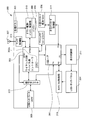
- FIG. 2 is a diagram showing an internal configuration of the wireless USB device.
- the wireless USB device 300 has a built-in USB hub 301.
- the wireless USB device 300 includes a wireless USB device-side controller 302 having a CPU 302a.
- the wireless USB device controller 302 controls various functions of the wireless USB device 300 by operating the CPU 302 a according to the firmware stored in the flash memory 308.
- the USB hub 301 has a function of distributing the output side signal of the wireless USB device side controller 302 to four ports P1 to P4.
- the wireless USB device 300 functions as a host for a device connected to each port of the USB hub 301.
- FIG. 2 also shows the various buttons 303 and the LCD touch panel 304 shown in FIG. 1 described above.
- the wireless USB device 300 includes a USB interface connector 305 and a small memory card dedicated connector 306 as shown in FIG. 2. These connectors 305 and 306 are used to connect cables and devices outside the wireless USB device 300. That is, the USB interface connector 305 is connected to a USB cable, a USB device, or the like.
- a small memory card dedicated connector 306 is connected to a small memory card such as an SD memory card (registered trademark) or a memory stick (registered trademark). Therefore, the small memory card dedicated connector 306 has a connector shape corresponding to the type of the small memory card to be connected.
- the wireless USB device 300 also includes a battery 309 and a wireless antenna 307. Furthermore, the wireless USB device 300 also includes a display control unit 311, a touch panel control unit 312, an antenna control unit 313, a small memory card control unit 314, and a button / power / battery control unit 310.
- the display control unit 311 controls images and characters on the LCD touch panel 304.
- the touch panel control unit 312 controls information input by a touch panel incorporated in the LCD touch panel 304.
- the display control unit 311 is connected to the port P1 of the USB hub 301, and the touch panel control unit 312 is connected to the port P2 of the USB hub 301. These display control unit 311 and touch panel control unit 312 operate as USB devices for the wireless USB device 300.
- the antenna control unit 313 is connected to the wireless USB device-side controller 302, and the wireless USB device-side controller 302 performs wireless communication according to the wireless USB standard via the antenna control unit 313.
- a combination of the wireless USB device-side controller 302 and the antenna control unit 313 corresponds to an example of a wireless communication unit that performs wireless communication with other devices.
- the wireless USB device 300 Prior to this wireless communication, the wireless USB device 300 requires mutual exchange of MAC addresses with the PC 200 shown in FIG. 1 as an initial setting. As a method for mutual exchange of MAC addresses, this wireless USB device 300 uses a cable association that connects a USB host connector on the host side and a USB interface connector 305 with a USB cable.
- the small memory card control unit 314 controls reading and writing of information to the small memory card via the small memory card dedicated connector 306.
- the small memory card control unit 314 also operates as a USB device for the wireless USB device 300 and is connected to the port P3 of the USB hub 301.
- the button / power / battery control unit 310 performs state monitoring of various buttons 303, power on / off control, battery charge state monitoring, and the like.
- the button / power source / battery control unit 310 is connected to the IO port GPIO2 of the wireless USB device-side controller 302 and notifies the USB device-side controller 302 of the state of various buttons 303 and the like.
- the USB interface connector 305 provided in the wireless USB device 300 is used for initial setting of wireless communication via the wireless antenna 307 and is also used for connecting the USB device to the USB hub 301. For this reason, the wireless USB device 300 is provided with a signal selector 315.
- the USB interface connector 305 is connected to the signal selector 315.
- the signal selector 315 is connected to the input side of the wireless USB device controller 302 and the P4 port of the USB hub 301 as a selection target by the signal selector 315.
- the signal selection by the signal selector 315 is determined by the output from the IO port GPIO1 of the wireless USB device controller 302. That is, when the output of the IO port GPIO1 is “L”, the signal selector 315 connects the input side of the wireless USB device-side controller 302 to the USB interface connector 305.
- the wireless USB device 300 operates as a USB device for the host device connected to the USB interface connector 305.
- the wireless USB device-side controller 302 executes cable association via the USB interface connector 305. That is, the wireless USB device-side controller 302 corresponds to an example of a setting execution unit that executes setting for wireless communication by wired communication.
- the signal selector 315 connects the P4 port of the USB hub 301 to the USB interface connector 305.
- the wireless USB device 300 operates as a host device for the USB device connected to the USB interface connector 305. That is, the USB hub 301 corresponds to an example of another function execution unit that executes a function different from the setting for wireless communication.
- the output from the IO port GPIO1 that determines the signal selection by the signal selector 315 is set according to the result of the wireless USB device-side controller 302 monitoring the wireless communication state of the wireless USB.
- the wireless USB device-side controller 302 sets the output from the IO port GPIO1 to “H”. Therefore, the wireless USB device-side controller 302 corresponds to an example of a wireless communication confirmation unit that confirms whether or not a connection with another device by wireless communication is established. Further, the wireless USB device-side controller 302 corresponds to an example of a selection unit that selects another function execution unit and executes the other function.
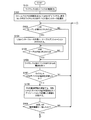
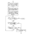
- FIGS. 3 and 4 are flowcharts showing the operation of the wireless USB device.
- FIG. 3 shows the first half of the flowchart
- FIG. 4 shows the second half of the flowchart. That is, step S109 shown in FIG. 3 is connected to step S110 shown in FIG.
- the operations represented in FIGS. 3 and 4 correspond to an embodiment of the function switching method described above.
- the host-side device is the PC 200 shown in FIG.
- the wireless USB device controller 302 sets the output of the IO port GPIO1 to “L” as an initial state (step S102). As a result, the input side of the wireless USB device controller 302 is connected to the USB interface connector 305. Since the wireless USB device 300 in the initial state does not exchange each other's information even if radio waves are transmitted from the PC 200 shown in FIG. 1, it cannot be recognized as a partner even if it can receive radio waves, and should be connected as a wireless USB. I can't.
- the wireless USB device controller 302 recognizes whether the USB cable is connected to the USB interface connector 305 by monitoring the USB signals D + and D ⁇ via the USB interface connector 305 (step S103). Since this signal is fixed to “L” by the pull-down resistor when not connected, when the signals D + and D ⁇ are “L”, the wireless USB device controller 302 recognizes that they are not connected. On the other hand, when the USB cable is connected to the PC 200 and the wireless USB device 300, one of the signals D + and D ⁇ is pulled up to “H” on the USB device side. Accordingly, when either of the signals D + and D ⁇ becomes “H”, the wireless USB device controller 302 recognizes the connection.
- FIG. 5 is a diagram illustrating a state in which the PC and the wireless USB device are connected by a USB cable.
- the user of the wireless USB device 300 connects the PC 200 and the wireless USB device 300 with the USB cable 400 for cable association.
- step S104 cable association using the USB interface is executed.
- This step S104 corresponds to an example of the setting execution process.
- the connection is recognized on the PC 200 side by the internal function of the PC 200.
- the PC 200 starts communication with the USB device according to the USB protocol.
- the PC 200 recognizes the wireless USB device 300, installs dedicated driver software, and controls the wireless USB device 300 as a USB device.
- the wireless USB device 300 is controlled as a USB device, radio waves transmitted from the PC 200 are temporarily stopped.
- the information of the PC 200 is transmitted to the wireless USB device 300 side according to the USB communication protocol via the USB cable 400, and the transmitted information is stored in the flash memory 308.
- the information of the wireless USB device 300 is transmitted to the PC 200 side, and the transmitted information is stored in a storage unit in the PC 200.
- the user of the wireless USB device 300 removes the USB cable 400 when the cable association is completed. Note that the user determines the end of the cable association using the wireless USB application on the PC 200. When the USB cable 400 is removed after the cable association is completed, the PC 200 transmits radio waves again.
- the wireless USB device 300 that has finished exchanging information by cable association recognizes whether or not the cable has been removed via the USB interface connector 305 in step S105 of FIG. 3 (step S105).
- the recognition method in step S105 is the same as the recognition method in step S103 described above. If it is recognized that the wireless USB device 300 has been removed, the process advances to step S106, and the wireless USB device 300 waits for reception of radio waves.
- radio waves are received by the wireless USB device 300 (step S107), it is confirmed whether or not the identification information (MAC address) represented by the received radio waves matches the stored identification information of the PC 200 (step S107). Step S108).
- identification information of the wireless USB device 300 is transmitted to the PC 200 by radio waves.
- step S108 corresponds to an example of the wireless communication confirmation process.
- step S109 If the identification information transmitted by radio waves matches the identification information stored in each device (step S109; Yes), the process proceeds to step S110 in FIG. Continue communication connection.
- This connection is realized by the driver used in the cable association operating as a wireless USB.
- This step S110 corresponds to an example of the above-described wireless communication process.
- the wireless USB device-side controller 302 sets the output of the IO port GPIO1 to “H” (step S111).
- the P4 port (output side) of the USB hub 301 is connected to the USB interface connector 305 by switching the signal selector.
- the USB interface connector 305 functions as a USB host connector (step S112). That is, a USB memory or the like can be connected to the USB interface connector 305.
- This step S112 corresponds to an example of the separate function execution process.
- FIG. 6 is a diagram illustrating an operation example after connection of the wireless USB.
- the PC 200 and the wireless USB device 300 are connected to each other by a wireless USB.
- the wireless USB device 300 is used as a sub-screen of the screen of the PC 200 as described above. Further, as shown in FIG. 6, a USB memory 500 or the like can be connected to the wireless USB device 300.
- This wireless USB device 300 is provided with only one USB interface connector as described above. However, after the cable association becomes unnecessary, the USB interface connector is effectively used by the operation shown in FIG. Accordingly, since an extra USB interface connector is not required, the wireless USB device 300 can be reduced in size.
- step S113 when the power of the wireless USB device 300 is turned off by a user operation (step S113; Yes), the operation of the flowcharts shown in FIGS. 3 and 4 ends. If the power of the wireless USB device 300 remains on (step S113; No), the process proceeds to step S114. In step S114, if neither a disconnection request from the PC nor a power-off of the PC has occurred (step S114; No), the process proceeds to step S115. Further, in step S115, if communication disconnection due to deterioration in communication quality has not occurred (step S115; No), the process returns to step S113. That is, after step S112 shown in FIG. 4, only the determinations of steps S113 to S115 are repeated while the communication is normally maintained.
- step S114 If it is determined in step S114 that either a disconnection request from the PC or a power-off of the PC has occurred, the process proceeds to step S116. If the communication disconnection occurs due to the deterioration of the communication quality in step S115, the process proceeds to step S116. In these cases, re-cable association is required. Therefore, in step S116, the output of the IO port GPIO1 is set to “L” by the wireless USB device-side controller 302, and the operation returns to step S103 in FIG. As a result, the input side of the wireless USB device controller 302 is connected to the USB interface connector 305 again. That is, the cable association can be performed again.
- step S103 Operation returns.
- the wireless USB device 300 switches functions for re-cable association. This means that the following application forms are suitable.
- the wireless communication confirmation unit selects the communication setting unit when the wireless communication confirmation unit confirms that the connection is not established. Is to execute.
- step S103 in FIG. 3 corresponds to each example of the setting re-execution process.
- the connector can be effectively used. As a result, this contributes to miniaturization of the wireless USB device.
Landscapes
- Engineering & Computer Science (AREA)
- Theoretical Computer Science (AREA)
- Physics & Mathematics (AREA)
- General Engineering & Computer Science (AREA)
- General Physics & Mathematics (AREA)
- Mobile Radio Communication Systems (AREA)
- Information Transfer Systems (AREA)
Abstract
コネクタの有効利用が図られた無線通信装置および機能切換方法を提供する。この無線通信装置は、コネクタと、他の機器と無線通信を行う無線通信部と、無線通信のための設定を、コネクタを介した他の機器との有線通信で実行する設定実行部と、コネクタに接続された機器を使った、無線通信のための設定とは別の機能を実行する別機能実行部と、無線通信部の無線通信による前記他の機器との接続が成立しているか否かを確認する無線通信確認部と、無線通信確認部で無線通信による接続の成立が確認された場合に、通信設定部と別機能実行部とのうち別機能実行部を選択して上記別の機能を実行させる選択部とを備える。
Description
本件開示は、無線通信装置、および機能切換方法に関する。
パーソナルコンピュータ(以下PCと略す)には、現在USB2.0という最大480Mbpsの転送速度を持ち周辺機器と容易に接続できる有線インターフェースが使われている。そして、このUSB2.0における有線部分を無線通信におきかえたワイヤレスUSBはUSB2.0と同等のインターフェース機能を有した技術である。ワイヤレスUSBでは、PCに代表されるホスト機器に専用の無線通信デバイスが設けられている。そして、この無線通信デバイスが用いられて、ワイヤレスUSBハブ等に代表されるワイヤレスUSBデバイスとホスト機器との無線アンテナを経由した通信が行われる。
上述したように、ワイヤレスUSBは、PC(ホスト側)とワイヤレスUSBデバイス(端末側)との間を無線で通信している以外はUSB2.0インターフェースと同じインターフェース機能を持っている。このため、ワイヤレスUSBデバイスの内部動作はUSB2.0の仕様を踏襲した動作となっている。
ワイヤレスUSBを使うことにより、端末側のUSB機器をPC(ホスト側)と繋げていた有線部分が無くなるため、有線ケーブルの引き回しを考慮する事もなく自由にUSB機器を配置できるようになる。
このようなワイヤレスUSBでUSBデバイスとPCが無線通信する場合は、初期設定としてお互いの機器情報(MACアドレス)を交換し、それぞれの記憶手段に記憶しておく必要がある。
この情報交換の一般的な方法としては、ワイヤレスUSBデバイスとPCの間を有線USBケーブルで接続し、そのケーブルを介した有線USB2.0インターフェースを通じて情報交換を行う方法が知られている。このような情報交換方法はケーブルアソシェーションと称されている。
このケーブルアソシェーションで情報交換を行っている最中は、ワイヤレスUSBデバイスはPCに対して有線のUSB2.0デバイスとして動作する。そのためワイヤレスUSBデバイス側には、有線のUSB2.0デバイスとして動作するためのケーブルアソシェーション専用のUSBインターフェースコネクタが設けられている。
ケーブルアソシェーションでお互いの機器情報(MACアドレス)を記憶した後は、ワイヤレスUSBデバイスとPCはお互いの電波を受信してワイヤレスUSBとして通信を行うこととなる。即ち、ワイヤレスUSBデバイスとしての本来の機能を実行することとなる。
このように本来の機能を実行しているワイヤレスUSBデバイスにおいては、初期設定に用いられた専用のUSBインターフェースコネクタは不要な状態となっている。
なお、USBインターフェースコネクタの機能やUSBデバイスの機能を切り替えるための技術的提案も知られている(例えば、特許文献1および特許文献2参照。)。
ワイヤレスUSBデバイスの更なる小型化を考えると、初期設定に用いられたケーブルアソシェーション専用のUSBインターフェースコネクタを、ワイヤレスUSBデバイスが本来の機能を実行している場合にも有効利用することが望ましい。しかし、特許文献1や特許文献2などに開示されている従来技術は、このような有効利用を目的にしていないため、技術を単純に流用しても、機能の切り替えが不適切になる場合がある。
また、単純に機械的スイッチで機能を切り替える方法が考えられるが、スイッチを取り付けるための追加のスペースが必要になり小型化の目的に反する結果となる。また、機械的なスイッチでの切り換えは使用者のオペレーションに依存することとなるが、オペレーションミス等の発生で誤動作の要因ともなって危険である。
なお、ここまでワイヤレスUSBデバイスを例として技術的な事情を説明したが、このような事情は、ワイヤレスUSBデバイスに限らず、無線通信の初期設定に有線を用いる無線通信装置について一般的に生じる事情である。
上記事情に鑑み、本件開示は、コネクタの有効利用が図られた無線通信装置、およびそのような有効利用を可能とする機能切換方法を提供することを目的とする。
上記目的を達成する無線通信装置は、コネクタと無線通信部と設定実行部と別機能実行部と無線通信確認部と選択部とを備えている。
上記無線通信部は、他の機器と無線通信を行うものである。
上記設定実行部は、上記無線通信のための設定を、上記コネクタを介した上記他の機器との有線通信で実行するものである。
上記別機能実行部は、上記コネクタに接続された機器を使った、上記設定とは別の機能を実行するものである。
上記無線通信確認部は、上記無線通信部による無線通信が成立しているか否かを確認するものである。
上記選択部は、上記無線通信確認部で無線通信の成立が確認された場合に、上記通信設定部と上記別機能実行部とのうち別機能実行部を選択して上記別の機能を実行させるものである。
上記目的を達成する機能切換方法は、無線通信装置で実行される機能切換方法であって、設定実行過程と無線通信過程と無線通信確認過程と別機能実行過程とを有する。
上記設定実行過程は、無線通信のための設定を、上記無線通信装置に備えられたコネクタを介した他の機器との有線通信で実行する過程である。
上記無線通信過程は、上記他の機器と無線通信を行う過程である。
上記無線通信確認過程は、上記無線通信が成立しているか否かを確認する過程である。
上記別機能実行過程は、上記無線通信の成立が確認された場合に、上記コネクタに接続された機器を使った、上記設定とは別の機能を実行させる過程である。
本件開示の無線通信装置および機能切換方法によれば、コネクタの有効利用が図られる。
上記説明した無線通信装置および機能切換方法に対する具体的な実施形態を、以下図面を参照して説明する。
図1は、上述した無線通信装置の一実施形態であるワイヤレスUSBデバイスを端末装置として含んだコンピュータシステムを示す図である。
このコンピュータシステム100は、パーソナルコンピュータ(PC)200とワイヤレスUSBデバイス300とを備えたシステムである。
ワイヤレスUSBデバイス300には、ユーザが各種の操作を行うための各種ボタン303が備えられている。また、ワイヤレスUSBデバイス300には、液晶ディスプレイ(LCD)にタッチパネルが組み込まれたLCDタッチパネル304も備えられている。このLCDタッチパネル304は、操作用に用意されたタッチペン304aや指先などで画面に触れることで操作される。
PC200とワイヤレスUSBデバイス300は、ワイヤレスUSBで互いに無線通信を行っている。そして、このワイヤレスUSBデバイス300は、その無線通信によってPC200に対する周辺機器として動作することで、例えば、PC200の画面に対するサブ画面などとして利用される。
図2は、ワイヤレスUSBデバイスの内部構成を示す図である。
ワイヤレスUSBデバイス300はUSBハブ301を内蔵している。また、ワイヤレスUSBデバイス300は、CPU302aを有したワイヤレスUSBデバイス側コントローラ302を備えている。フラッシュメモリ308に記憶されたファームウェアに従ってCPU302aが動作することでワイヤレスUSBデバイス側コントローラ302はワイヤレスUSBデバイス300の各種機能を制御する。USBハブ301はワイヤレスUSBデバイス側コントローラ302の出力側の信号をP1~P4の4つのポートに分配する機能を有している。ワイヤレスUSBデバイス300は、USBハブ301の各ポートに接続される装置に対するホストとして機能する。
この図2には、上述した図1に示した各種ボタン303およびLCDタッチパネル304も示されている。また、図1では図示および説明を省略したが、この図2に示されているように、ワイヤレスUSBデバイス300は、USBインターフェースコネクタ305と、小型メモリカード専用コネクタ306を備えている。これらのコネクタ305,306は、ワイヤレスUSBデバイス300外のケーブルや機器が接続されるものである。即ち、USBインターフェースコネクタ305には、USBケーブルやUSBデバイスなどが接続される。一方、小型メモリカード専用コネクタ306には、SDメモリカード(登録商標)やメモリースティック(登録商標)などといった小型メモリカードが接続される。このため小型メモリカード専用コネクタ306は、接続される小型メモリカードの種類に応じたコネクタ形状を有している。
ワイヤレスUSBデバイス300は、バッテリー309や無線アンテナ307も内蔵している。更に、ワイヤレスUSBデバイス300は、表示制御部311、タッチパネル制御部312、アンテナ制御部313、小型メモリカード制御部314、およびボタン・電源・バッテリー制御部310も内蔵している。表示制御部311は、LCDタッチパネル304における画像や文字の制御を行う。タッチパネル制御部312は、LCDタッチパネル304に組み込まれたタッチパネルによる情報入力を制御する。表示制御部311はUSBハブ301のポートP1に繋がり、タッチパネル制御部312はUSBハブ301のポートP2に繋がっている。これら表示制御部311およびタッチパネル制御部312は、ワイヤレスUSBデバイス300に対するUSBデバイスとして動作している。
アンテナ制御部313は、ワイヤレスUSBデバイス側コントローラ302に繋がっており、ワイヤレスUSBデバイス側コントローラ302はワイヤレスUSBの規格に則った無線通信をアンテナ制御部313を介して行う。ワイヤレスUSBデバイス側コントローラ302およびアンテナ制御部313を合わせたものが、他の機器と無線通信を行う無線通信部の一例に相当する。この無線通信に先だって、ワイヤレスUSBデバイス300は、初期設定として、図1に示すPC200とのMACアドレスの相互交換を必要とする。MACアドレスの相互交換の方法として、このワイヤレスUSBデバイス300は、ホスト側が有しているUSBホストコネクタとUSBインターフェースコネクタ305をUSBケーブルで繋ぐケーブルアソシェーションを使用する。
小型メモリカード制御部314は、小型メモリカード専用コネクタ306を介した小型メモリカードへの情報の読み書きを制御する。この小型メモリカード制御部314もワイヤレスUSBデバイス300に対するUSBデバイスとして動作するものであって、USBハブ301のポートP3に繋がっている。
ボタン・電源・バッテリー制御部310は、各種ボタン303の状態監視や電源のオンオフ制御やバッテリーの充電状態監視などを行う。ボタン・電源・バッテリー制御部310は、ワイヤレスUSBデバイス側コントローラ302のIOポートGPIO2に繋がっていて各種ボタン303の状態などをUSBデバイス側コントローラ302に通知する。
このワイヤレスUSBデバイス300に備えられているUSBインターフェースコネクタ305は、無線アンテナ307を介した無線通信の初期設定用に用いられると共に、USBハブ301に対するUSBデバイスの接続用としても用いられる。このためワイヤレスUSBデバイス300には信号セレクタ315が備えられている。
USBインターフェースコネクタ305は、信号セレクタ315に繋がっている。その信号セレクタ315には、その信号セレクタ315による選択対象として、ワイヤレスUSBデバイス側コントローラ302の入力側とUSBハブ301のP4ポートが繋がっている。信号セレクタ315による信号選択は、ワイヤレスUSBデバイス側コントローラ302のIOポートGPIO1からの出力によって決まる。即ち、IOポートGPIO1の出力が”L”の時、信号セレクタ315は、ワイヤレスUSBデバイス側コントローラ302の入力側をUSBインターフェースコネクタ305に接続する。これにより、ワイヤレスUSBデバイス300は、USBインターフェースコネクタ305に接続されるホスト装置に対するUSBデバイスとして動作する。そして、ワイヤレスUSBデバイス側コントローラ302は、USBインターフェースコネクタ305を介してケーブルアソシェーションを実行する。つまり、ワイヤレスUSBデバイス側コントローラ302は、無線通信のための設定を有線通信で実行する設定実行部の一例に相当する。また、IOポートGPIO1の出力が”H”の時、信号セレクタ315は、USBハブ301のP4ポートをUSBインターフェースコネクタ305に接続する。これにより、ワイヤレスUSBデバイス300は、USBインターフェースコネクタ305に接続されるUSBデバイスに対してホスト装置として動作する。つまり、USBハブ301が、無線通信のため設定とは別の機能を実行する別機能実行部の一例に相当する。
このような信号セレクタ315による信号選択を決めるIOポートGPIO1からの出力は、ワイヤレスUSBデバイス側コントローラ302が、ワイヤレスUSBの無線通信の状態を監視した結果に応じて設定している。詳しくは後述するが、ワイヤレスUSBの規格に則った無線通信の接続が成立するとワイヤレスUSBデバイス側コントローラ302はIOポートGPIO1からの出力を”H”に設定する。従って、ワイヤレスUSBデバイス側コントローラ302は、無線通信による他の機器との接続が成立しているか否かを確認する無線通信確認部の一例に相当する。更に、ワイヤレスUSBデバイス側コントローラ302は、別機能実行部を選択して上記別の機能を実行させる選択部の一例にも相当する。
以下、ワイヤレスUSBデバイス300の動作をフローチャートを参照して説明する。
図3および図4はワイヤレスUSBデバイスの動作を表すフローチャートである。図3には、フローチャートの前半部分が示されており、図4には、フローチャートの後半部分が示されている。即ち、図3に示すステップS109は、図4に示すステップS110へと繋がっている。この図3および図4で表された動作は、上述した機能切換方法の一実施形態に相当する。以下、このフローチャートを参照してワイヤレスUSBデバイス300の動作を説明するに当たり、図2に記載の要素については特に図番を断らずに符号で参照する。また、以下の説明では、ホスト側の装置は図1に示すPC200であるものとする。
ユーザの操作によってワイヤレスUSBデバイス300の電源がONになる(ステップS101)と、ワイヤレスUSBデバイス側コントローラ302は、初期状態としてIOポートGPIO1の出力を”L”に設定する(ステップS102)。これにより、ワイヤレスUSBデバイス側コントローラ302の入力側がUSBインターフェースコネクタ305に接続される。初期状態のワイヤレスUSBデバイス300は、図1に示すPC200から電波が発信されていても互いの情報を交換していないので、電波を受信できても相手として認識できず、ワイヤレスUSBとして接続することもできない。
ワイヤレスUSBデバイス側コントローラ302は、USBインターフェースコネクタ305を介してUSBの信号D+,D-をモニタすることで、USBインターフェースコネクタ305にUSBケーブルが接続されたか否かを認識する(ステップS103)。この信号は未接続時プルダウン抵抗により”L”に固定されているため、信号D+,D-が”L”である場合にはワイヤレスUSBデバイス側コントローラ302により未接続と認識される。一方、USBケーブルがPC200とワイヤレスUSBデバイス300とに繋がった場合、USBデバイス側は信号D+,D-のどちらかがプルアップされていて”H”になる。従って、信号D+,D-のどちらかが”H”になった場合にはワイヤレスUSBデバイス側コントローラ302により接続が認識される。
図5は、PCとワイヤレスUSBデバイスがUSBケーブルで接続された様子を示す図である。
ワイヤレスUSBデバイス300のユーザは、ケーブルアソシェーションのためにPC200とワイヤレスUSBデバイス300をUSBケーブル400で接続する。
このようにUSBケーブル400で接続されると、ワイヤレスUSBデバイスでは、図3のステップS103で接続が認識される。そして、ステップS104に進み、USBインターフェースを使ったケーブルアソシェーションが実行される。このステップS104が上記設定実行過程の一例に相当する。このケーブルアソシエーションでは、PC200側で、PC200の内部機能によって接続が認識される。そしてPC200は、USBのプロトコルに従いUSBデバイスとの通信を開始する。PC200はワイヤレスUSBデバイス300を認識して専用のドライバソフトをインストールし、ワイヤレスUSBデバイス300をUSBデバイスとして制御する。この時ワイヤレスUSBデバイス300をUSBデバイスとして制御するため、PC200から発信されている電波は一時的に停止する。また、USBケーブル400を経由してUSBの通信プロトコルにしたがってPC200の情報がワイヤレスUSBデバイス300側に送信され、その送信された情報はフラッシュメモリ308に記憶される。一方、ワイヤレスUSBデバイス300の情報はPC200側に送信され、その送信された情報はPC200内の記憶手段に記憶される。
ワイヤレスUSBデバイス300のユーザは、ケーブルアソシェーションが終了するとUSBケーブル400を取り外す。なお、ユーザは、ケーブルアソシェーションの終了を、PC200上のワイヤレスUSBのアプリケーションを使って判断する。PC200は、ケーブルアソシェーションの終了後にUSBケーブル400が取り外されると再び電波を発信する。
一方、ケーブルアソシェーションで情報交換を終えたワイヤレスUSBデバイス300は、図3のステップS105で、USBインターフェースコネクタ305を介して、ケーブルが取り外されたか否かを認識する(ステップS105)。このステップS105での認識方法は、上述したステップS103での認識方法と同様である。そして、取り外されたと認識されるとステップS106に進み、ワイヤレスUSBデバイス300は電波の受信を待つ。ワイヤレスUSBデバイス300によって電波が受信される(ステップS107)と、受信した電波が表している識別情報(MACアドレス)が、記憶しているPC200の識別情報と一致するか否かが確認される(ステップS108)。また、同時に、PC200に対してワイヤレスUSBデバイス300の識別情報が電波で送信される。PC200側でも、電波で送られてきた識別情報とケーブルアソシェーションで記憶した識別情報とが比較される。このように識別情報の一致が確認されることにより、ワイヤレスUSBに則った無線通信接続の成立が確認される。つまり、ステップS108は、上記無線通信確認過程の一例に相当する。
電波で送信されたお互いの識別情報が、お互いの装置内に記憶されている識別情報と一致した場合(ステップS109;Yes)には、図4のステップS110に進んで、ワイヤレスUSBに則った無線通信の接続を続ける。この接続は、ケーブルアソシェーションで使われたドライバがワイヤレスUSBとして動作することで実現される。このステップS110が、上述した無線通信過程の一例に相当する。
このように、ワイヤレスUSBの接続が行われると、USBインターフェースコネクタ305のケーブルアソシェーション用としての役割は不要になる。そこで、ワイヤレスUSBデバイス側コントローラ302は、IOポートGPIO1の出力を”H”に設定する(ステップS111)。この結果、信号セレクタの切り替えによってUSBハブ301のP4ポート(出力側)がUSBインターフェースコネクタ305に接続されることとなる。そして、USBインターフェースコネクタ305は、USBホストコネクタとして機能する(ステップS112)。つまり、USBインターフェースコネクタ305にUSBメモリなどを接続することが可能となる。このステップS112が、上記別機能実行過程の一例に相当する。
図6は、ワイヤレスUSBの接続後の運用例を示す図である。
PC200とワイヤレスUSBデバイス300はワイヤレスUSBによって互いに接続されている。そしてワイヤレスUSBデバイス300は、上述したように、PC200の画面のサブ画面などとして利用される。また、この図6に示すように、ワイヤレスUSBデバイス300にはUSBメモリ500などを接続することができる。このワイヤレスUSBデバイス300には、上述したようにUSBインターフェースコネクタが1つしか設けられていない。しかし、ケーブルアソシェーションが不要となった後は、この図6に示すような運用により、USBインターフェースコネクタが有効利用される。従って、余分なUSBインターフェースコネクタが不要となるのでワイヤレスUSBデバイス300の小型化が図られる。
図4に示すステップS112の後は、ユーザ操作によってワイヤレスUSBデバイス300の電源がOFFになる(ステップS113;Yes)と図3および図4に示すフローチャートの動作は終了する。ワイヤレスUSBデバイス300の電源がONのまま(ステップS113;No)の場合はステップS114に進む。また、このステップS114で、PCからの切断要求もPCの電源断も生じていない(ステップS114;No)場合はステップS115に進む。更に、このステップS115で、通信品質の悪化による通信切断が生じていないステップS115;No)場合はステップS113に戻る。つまり、図4に示すステップS112の後は、通信が正常に維持されている間は、ステップS113~ステップS115の判断だけが繰り返されることとなる。
ステップS114で、PCからの切断要求、またはPCの電源断のいずれかが生じた場合はステップS116に進む。また、ステップS115で通信品質の悪化による通信切断が生じた場合もステップS116に進む。これらの場合には、再度のケーブルアソシェーションが必要となる。そこで、ステップS116では、ワイヤレスUSBデバイス側コントローラ302によってIOポートGPIO1の出力が”L”に設定されて、図3のステップS103へと動作が戻る。これにより、ワイヤレスUSBデバイス側コントローラ302の入力側が再びUSBインターフェースコネクタ305に接続される。つまり、ケーブルアソシェーションが再度可能な状態になる。
また、上述したステップS107でワイヤレスUSBデバイス300が電波を受信できなかった場合や、上述したステップS109で識別情報が不一致であった場合にも、再度のケーブルアソシェーションが必要なのでステップS103へと動作が戻る。
このように、ワイヤレスUSBデバイス300は、ワイヤレスUSBの接続が不成立となった場合には、再度のケーブルアソシェーションのために機能を切り替える。このことは、以下のような応用形態が好適であることを意味している。
この応用形態では、上記選択部は、上記別機能実行部を選択した後で、上記無線通信確認部で無線通信による接続の不成立が確認された場合には上記通信設定部を選択して上記設定を実行させるものである。
あるいはこの応用形態では、上記別機能実行過程の後で上記無線通信による接続の不成立が確認された場合に上記設定を実行させる設定再実行過程を有する。
図3のステップS103へと動作を戻す各ステップは、この設定再実行過程の各一例に相当する。
以上説明したように、図2に示すワイヤレスUSBデバイス300や図3および図4に示す動作によれば、コネクタの有効利用が図られる。その結果、ワイヤレスUSBデバイスの小型化などにも寄与することとなる。
100 コンピュータシステム
200 パーソナルコンピュータ
300 ワイヤレスUSBデバイス
303 各種ボタン
304 LCDタッチパネル
301 USBハブ
302 ワイヤレスUSBデバイス側コントローラ
305 USBインターフェースコネクタ
306 小型メモリカード専用コネクタ
307 内蔵アンテナ
308 フラッシュメモリ
309 バッテリー
315 信号セレクタ
400 USBケーブル
500 USBメモリ
200 パーソナルコンピュータ
300 ワイヤレスUSBデバイス
303 各種ボタン
304 LCDタッチパネル
301 USBハブ
302 ワイヤレスUSBデバイス側コントローラ
305 USBインターフェースコネクタ
306 小型メモリカード専用コネクタ
307 内蔵アンテナ
308 フラッシュメモリ
309 バッテリー
315 信号セレクタ
400 USBケーブル
500 USBメモリ
Claims (4)
- コネクタと、
他の機器と無線通信を行う無線通信部と、
前記無線通信のための設定を、前記コネクタを介した前記他の機器との有線通信で実行する設定実行部と、
前記コネクタに接続された機器を使った、前記設定とは別の機能を実行する別機能実行部と、
前記無線通信部の無線通信による前記他の機器との接続が成立しているか否かを確認する無線通信確認部と、
前記無線通信確認部で無線通信による接続の成立が確認された場合に、前記通信設定部と前記別機能実行部とのうち別機能実行部を選択して前記別の機能を実行させる選択部と、
を備えたことを特徴とする無線通信装置。 - 前記選択部は、前記別機能実行部を選択した後で、前記無線通信確認部で無線通信による接続の不成立が確認された場合には前記通信設定部を選択して前記設定を実行させるものであることを特徴とする請求項1記載の無線通信装置。
- 無線通信装置で実行される機能切換方法であって、
無線通信のための設定を、前記無線通信装置に備えられたコネクタを介した他の機器との有線通信で実行する設定実行過程と、
前記他の機器と無線通信を行う無線通信過程と、
前記無線通信過程の無線通信による前記他の機器との接続が成立しているか否かを確認する無線通信確認過程と、
前記無線通信による接続の成立が確認された場合に、前記コネクタに接続された機器を使った、前記設定とは別の機能を実行させる別機能実行過程と、
を有することを特徴とする機能切換方法。 - 前記別機能実行過程の後で前記無線通信による接続の不成立が確認された場合に前記設定を実行させる設定再実行過程を有することを特徴とする請求項3記載の機能切換方法。
Priority Applications (2)
| Application Number | Priority Date | Filing Date | Title |
|---|---|---|---|
| JP2012500429A JP5648678B2 (ja) | 2010-02-19 | 2010-02-19 | 無線通信装置、および機能切換方法 |
| PCT/JP2010/052518 WO2011101977A1 (ja) | 2010-02-19 | 2010-02-19 | 無線通信装置、および機能切換方法 |
Applications Claiming Priority (1)
| Application Number | Priority Date | Filing Date | Title |
|---|---|---|---|
| PCT/JP2010/052518 WO2011101977A1 (ja) | 2010-02-19 | 2010-02-19 | 無線通信装置、および機能切換方法 |
Publications (1)
| Publication Number | Publication Date |
|---|---|
| WO2011101977A1 true WO2011101977A1 (ja) | 2011-08-25 |
Family
ID=44482595
Family Applications (1)
| Application Number | Title | Priority Date | Filing Date |
|---|---|---|---|
| PCT/JP2010/052518 Ceased WO2011101977A1 (ja) | 2010-02-19 | 2010-02-19 | 無線通信装置、および機能切換方法 |
Country Status (2)
| Country | Link |
|---|---|
| JP (1) | JP5648678B2 (ja) |
| WO (1) | WO2011101977A1 (ja) |
Cited By (1)
| Publication number | Priority date | Publication date | Assignee | Title |
|---|---|---|---|---|
| CN103533007A (zh) * | 2012-07-05 | 2014-01-22 | 仁宝电脑工业股份有限公司 | 切换数据传输路径以传输数据的方法及储存装置 |
Citations (3)
| Publication number | Priority date | Publication date | Assignee | Title |
|---|---|---|---|---|
| JP2004110145A (ja) * | 2002-09-13 | 2004-04-08 | Matsushita Electric Ind Co Ltd | Usbコネクタ接続装置、usbコネクタ接続方法、usbコネクタ接続プログラムおよびusb接続プログラムを記録した媒体 |
| JP2007279834A (ja) * | 2006-04-03 | 2007-10-25 | Canon Inc | 認証システム、認証方法 |
| JP2008257419A (ja) * | 2007-04-04 | 2008-10-23 | Nec Electronics Corp | 通信アダプタ及び通信アダプタのデータ転送方法 |
Family Cites Families (2)
| Publication number | Priority date | Publication date | Assignee | Title |
|---|---|---|---|---|
| JP2007219909A (ja) * | 2006-02-17 | 2007-08-30 | Seiko Epson Corp | ネットワーク対応型情報処理装置、設定方法及びそのプログラム |
| JP2007295084A (ja) * | 2006-04-21 | 2007-11-08 | Oki Data Corp | 無線端末管理システム |
-
2010
- 2010-02-19 JP JP2012500429A patent/JP5648678B2/ja not_active Expired - Fee Related
- 2010-02-19 WO PCT/JP2010/052518 patent/WO2011101977A1/ja not_active Ceased
Patent Citations (3)
| Publication number | Priority date | Publication date | Assignee | Title |
|---|---|---|---|---|
| JP2004110145A (ja) * | 2002-09-13 | 2004-04-08 | Matsushita Electric Ind Co Ltd | Usbコネクタ接続装置、usbコネクタ接続方法、usbコネクタ接続プログラムおよびusb接続プログラムを記録した媒体 |
| JP2007279834A (ja) * | 2006-04-03 | 2007-10-25 | Canon Inc | 認証システム、認証方法 |
| JP2008257419A (ja) * | 2007-04-04 | 2008-10-23 | Nec Electronics Corp | 通信アダプタ及び通信アダプタのデータ転送方法 |
Cited By (1)
| Publication number | Priority date | Publication date | Assignee | Title |
|---|---|---|---|---|
| CN103533007A (zh) * | 2012-07-05 | 2014-01-22 | 仁宝电脑工业股份有限公司 | 切换数据传输路径以传输数据的方法及储存装置 |
Also Published As
| Publication number | Publication date |
|---|---|
| JP5648678B2 (ja) | 2015-01-07 |
| JPWO2011101977A1 (ja) | 2013-06-17 |
Similar Documents
| Publication | Publication Date | Title |
|---|---|---|
| US8037225B2 (en) | Communication system with host and device role switching features | |
| CN108370430B (zh) | 信息处理设备、图像拾取设备、信息处理系统、信息处理方法和非暂时性计算机可读介质 | |
| JPWO2005001701A1 (ja) | スレイブ装置、通信設定方法 | |
| JP4586089B2 (ja) | 通信システム、ホスト装置及び端末装置 | |
| JP2001306495A (ja) | 携帯通信端末 | |
| JP5565142B2 (ja) | 情報処理装置、情報処理装置制御方法及び情報処理装置制御プログラムを格納した記録媒体 | |
| KR20110049121A (ko) | 디바이스 활성화 방법 및 장치 | |
| EP2860627A1 (en) | Active usb device and switching method for operating mode thereof | |
| TWI463364B (zh) | 觸控裝置之外部操作系統與方法 | |
| JP5242816B1 (ja) | 通信装置、プログラム、及び通信方法 | |
| JP2007134782A (ja) | 通信装置及び通信制御方法 | |
| JP5648678B2 (ja) | 無線通信装置、および機能切換方法 | |
| JP2012014343A (ja) | 周辺装置を利用するためのシステム、サーバ装置、方法 | |
| WO2012000240A1 (zh) | 下载数据的方法和终端设备 | |
| JP2005173820A (ja) | 周辺装置、および再接続プログラム | |
| US12493572B2 (en) | Universal serial bus architecture | |
| US12432796B2 (en) | Smart enumeration for a dongle | |
| US10165612B2 (en) | Wireless connecting method, computer, and non-transitory computer-readable storage medium | |
| US20140347279A1 (en) | Keyboard device with switchable connection path and its switching method | |
| WO2014104398A1 (ja) | 携帯端末、携帯端末の制御方法、およびデバイス制御システム | |
| JP2018185664A (ja) | 制御システム、電子機器および制御方法 | |
| CN108388534A (zh) | 一种显示器及显示器程序升级的方法 | |
| JP2004110145A (ja) | Usbコネクタ接続装置、usbコネクタ接続方法、usbコネクタ接続プログラムおよびusb接続プログラムを記録した媒体 | |
| CN111988065A (zh) | 一种免驱动usb设备、方法、存储介质及设备 | |
| KR20050102824A (ko) | Usb 접속제어버튼을 이용한 usb접속 제어장치 및 방법 |
Legal Events
| Date | Code | Title | Description |
|---|---|---|---|
| 121 | Ep: the epo has been informed by wipo that ep was designated in this application |
Ref document number: 10846114 Country of ref document: EP Kind code of ref document: A1 |
|
| WWE | Wipo information: entry into national phase |
Ref document number: 2012500429 Country of ref document: JP |
|
| NENP | Non-entry into the national phase |
Ref country code: DE |
|
| 122 | Ep: pct application non-entry in european phase |
Ref document number: 10846114 Country of ref document: EP Kind code of ref document: A1 |