WO2011096254A1 - カメラコントロールユニット、及び該カメラコントロールユニットを備えたカメラシステム - Google Patents
カメラコントロールユニット、及び該カメラコントロールユニットを備えたカメラシステム Download PDFInfo
- Publication number
- WO2011096254A1 WO2011096254A1 PCT/JP2011/050337 JP2011050337W WO2011096254A1 WO 2011096254 A1 WO2011096254 A1 WO 2011096254A1 JP 2011050337 W JP2011050337 W JP 2011050337W WO 2011096254 A1 WO2011096254 A1 WO 2011096254A1
- Authority
- WO
- WIPO (PCT)
- Prior art keywords
- camera
- video signal
- external device
- unit
- control unit
- Prior art date
- Legal status (The legal status is an assumption and is not a legal conclusion. Google has not performed a legal analysis and makes no representation as to the accuracy of the status listed.)
- Ceased
Links
Images


Classifications
-
- H—ELECTRICITY
- H04—ELECTRIC COMMUNICATION TECHNIQUE
- H04N—PICTORIAL COMMUNICATION, e.g. TELEVISION
- H04N23/00—Cameras or camera modules comprising electronic image sensors; Control thereof
- H04N23/60—Control of cameras or camera modules
- H04N23/66—Remote control of cameras or camera parts, e.g. by remote control devices
Definitions
- the present invention relates to a camera control unit that appropriately processes a video signal from a camera head unit and transmits it to an external device, and a camera system including the camera control unit.
- a home video camera or the like has a camera head unit and a camera control unit that are integrally incorporated in one device, but these units are not integrated but separated and are dedicated.
- Camera systems connected with cables are commercially available.
- Such a camera system is widely used for monitoring a production line in a factory, for building security, and the like, and various types of camera systems have been proposed (for example, see Patent Documents 1 and 2).
- FIG. 3 is a block diagram showing an example of a conventional configuration of such a camera system.
- Reference numeral 101 denotes a camera control unit
- reference numeral 102 denotes a camera head unit
- reference numeral 104 denotes the units 101 and 102.
- a camera cable to be connected is shown.
- Reference numeral 103 denotes an external device (for example, a monitor or a capture board) connected to the camera control unit 101.
- a camera head unit 102 is installed on the production line, and an image captured by the camera head unit 102 is transferred to a personal computer (not shown) via the camera control unit 101 or the capture board 103. Inferior goods are judged and robots are operated by taking in and image processing of the personal computer.
- An object of the present invention is to provide a camera control unit that can solve the above-described problems and a camera system that includes the camera control unit.
- the invention according to claim 1 is illustrated in FIG. 1 and processes a video signal (S D ) from the camera head unit (2) and transmits it to an external device (3).
- a camera cable connection portion (10) capable of connecting a camera cable (4) connected to a digital camera head unit (2)
- An external device connection section (11) to which the external device (3) can be connected
- An image memory unit (12) having a plurality of storage areas (see reference numerals 12A, 12B,... In FIG. 2) and storing the digital video signal (S D ) from the camera head unit (2) for each image; Of the plurality of storage areas (12A, 12B,...),
- the latest image sent from the camera head unit (2) is stored in the area where the digital video signal (S D ) of the oldest image is stored.
- the invention according to claim 2 is the invention according to claim 1, wherein the external device (3) is a capture board or a monitor.
- the invention according to claim 3 is a camera control unit (1) according to claim 1 or 2, A camera cable (4) connected to the camera cable connector (10); A digital camera head unit (2) connected to the camera cable (4);
- the present invention relates to a camera system including an external device (3) connected to the external device connection section (11) via an external device cable (5).
- the digital video signal from the camera head unit is converted into an analog format in the camera control unit. And by transmitting an analog video signal to the external device at an appropriate timing based on the synchronization signal from the external device (the camera head unit converts the video signal to the camera at a timing unrelated to the external device side).
- the video signal can be used on the external device side (even if transmitted to the control unit). Therefore, even when an analog system (that is, a camera system in which the camera head unit, camera control unit, and external devices are all analog systems) is already installed, the camera control unit is changed to the above-described configuration.
- an analog video signal can be output to the external device at a timing independent of the reception timing of the digital video signal by the image memory unit, the video signal rewriting unit, and the video signal reading unit. It is not necessary to receive HD signals and VD signals, which are necessary in conventional analog camera systems. As a result, the signal lines for HD and VD signals can be used for control communication signal transmission, and the conventional camera cables (used in analog camera systems) can be used as they are. It will be possible. This also enables digitalization with stepwise capital investment.
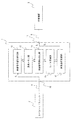
- FIG. 1 is a block diagram showing an example of the configuration of a camera control unit according to the present invention.
- FIG. 2 is a schematic diagram illustrating an example of the configuration of the image memory unit.
- FIG. 3 is a block diagram illustrating an example of a conventional configuration of a camera system.
- the camera control unit 1 appropriately processes the video signal SD from the camera head unit 2 and transmits it to the external device 3.
- the camera control unit 1 has a camera cable connection portion 10 to which a camera cable 4 can be connected, and is configured so that a digital camera head unit 2 can be connected to the camera cable 4. Is configured to sequentially receive image data (digital video signal) taken based on an arbitrary synchronization signal.
- the camera control unit 1 also includes an external device connection unit 11 that can connect an external device (for example, a capture board or a monitor) 3 that performs video recording or video display using a video signal.
- the external device 3 is connected to the external device connection unit 11 via a cable (external device cable) 5.
- the camera control unit 1 further includes an image memory unit 12 having a plurality of storage areas 12A, 12B,... (Four in FIG. 2), and the storage areas 12A, 12B,.
- the digital video signal from the camera head unit 2 can be stored for each image.
- the camera control unit 1 is sent from the camera head unit 2 to the area where the digital video signal of the oldest image is stored among the plurality of storage areas 12A, 12B,.
- a video signal rewriting unit 13 for rewriting and storing the latest digital video signal is provided.
- the image memory unit 12 always stores a plurality of latest image data.
- the camera control unit 1 is adapted to receive a synchronization signal S S from the connected external device 3, ⁇ Said plurality of said digital video signal of the newest image from the storage area synchronization signal S video signal readout unit 14 for reading, based on the timing of S (i.e., First in First not Out (FIFO).) And, ⁇ digital video signal S D read by the image signal readout section 14 and the D / A converter 15 for converting an analog video signal S A, A video signal transmitter 16 that transmits the converted analog video signal S A to the external device 3 at a timing based on the synchronization signal S S from the external device 3; It has.
- FIFO First in First not Out
- VD signal designating the timing of sending the image and can be exemplified HD signal designating the timing of the pixel spacing.
- the video signal transmission unit 16 sequentially transmits the video signal of the latest image in accordance with the interval of the HD signal at the timing of the VD signal.
- the digital video signal SD from the camera head unit 2 is converted into an analog format in the camera control unit 1.
- the analog video signal S A is transmitted to the external device 3 at an appropriate timing based on the synchronization signal S S from the external device 3 (the camera head unit is not related to the external device side). Even if the video signal is transmitted to the camera control unit at the timing, the video signal can be used on the external device side. Therefore, even when an analog system (that is, a camera system in which the camera head unit, camera control unit, and external devices are all analog systems) is already installed, the camera control unit is changed to the above-described configuration.
- the entire camera system can be operated even if the external device 3 remains in the conventional analog system.
- the camera control unit according to the present invention it is necessary to change the external device 3 to the digital system. Since there is no, digitalization can be achieved with gradual capital investment.
- the benefits of digitization can be received even at that stage (that is, the camera control unit having the above-described configuration, the camera head unit being a digital system, and the external device being an analog system).
- noise may display an image of lines, dots, or a combination thereof. May cause measurement errors.
- the camera control unit according to the present invention is used to make the camera head unit digital, the image due to noise becomes a pattern peculiar to the digital method (for example, block noise, burst noise, etc.), and it is easy to identify the noise. It can be recognized and measurement errors can be avoided.
- the image processing of the noise location can be avoided, and noise is generated even if the external device (for example, capture board) remains in the analog system Measurement errors associated with can be avoided.
- an example of a conventional analog camera cable has to support transmission / reception of four systems of video signals, HD signals, VD signals, and trigger signals. .
- the camera head unit digital it is necessary to transmit two systems of signals for control communication signals (signals for controlling camera head unit attributes such as gain and shutter speed, RS422).
- an analog video signal is output to the external device 3 at a timing independent of the reception timing of the digital video signal by the image memory unit 12, the video signal rewriting unit 13, and the video signal reading unit 14 described above. Therefore, it is not necessary to receive the HD signal and the VD signal that are necessary in the conventional analog camera system (see Table 2).
- signal lines for HD signals and VD signals can be used for transmission of control communication signals (RS422), and camera cables are conventional (used in analog camera systems). Can be used as is. This also enables digitalization with stepwise capital investment.
- the camera system includes: The camera control unit 1 configured as described above; A camera cable 4 connected to the camera cable connection unit 10; A digital camera head unit 2 connected to the camera cable 4; An external device 3 connected to the external device connection unit 11 via an external device cable 5; Consists of.
Landscapes
- Engineering & Computer Science (AREA)
- Multimedia (AREA)
- Signal Processing (AREA)
- Studio Devices (AREA)
- Television Signal Processing For Recording (AREA)
Abstract
【課題】カメラシステムのデジタル化を段階的な設備投資で行えるようにする。 【解決手段】カメラヘッドユニット2から順次送られてくるデジタル映像信号SDは画像メモリ部12に保存される。該保存されたデジタル映像信号SDはD/A変換部15にてアナログ映像信号SAに変換され、キャプチャーボード3からの同期信号SSに基づいたタイミングで該キャプチャーボード3に送信される。アナログ方式のカメラシステムをデジタル方式に変更する場合において、キャプチャーボード3は従来のアナログ方式のもので良いので、設備を一新する場合に比べて設備投資を抑えることができ、段階的な設備投資でのデジタル化を図ることが出来る。
Description
本発明は、カメラヘッドユニットからの映像信号を適宜処理して外部機器に伝送するカメラコントロールユニット、及び該カメラコントロールユニットを備えたカメラシステムに関する。
家庭用のビデオカメラなどは、カメラヘッドユニットとカメラコントロールユニットとが1つの装置の中に一体的に組み込まれて構成されているが、それらのユニットが一体化されずに分離されていて専用のケーブル(カメラケーブル)で接続されたカメラシステムが市販されている。このようなカメラシステムは、工場における生産ラインの監視用やビルディングのセキュリティ用等に広く利用されており、種々の構造のものが提案されている(例えば、特許文献1及び2参照。)。
図3は、そのようなカメラシステムの従来構成の一例を示すブロック図であり、符号101はカメラコントロールユニットを示し、符号102はカメラヘッドユニットを示し、符号104は、それらのユニット101,102を接続するカメラケーブルを示し、符号103は、カメラコントロールユニット101に接続される外部機器(例えば、モニターやキャプチャーボード)を示す。例えば、FA化された工場においては、生産ラインにカメラヘッドユニット102を設置しておき、該カメラヘッドユニット102で撮影した画像をカメラコントロールユニット101やキャプチャーボード103を介してパソコン(不図示)に取り込み、該パソコンの画像処理によって不良品の判断やロボットの操作などを行っていた。
ところで、このようなカメラシステムに関してはアナログ方式のものが長らく用いられて来たが、デジタル方式のものの方が解像度や画像処理の点で優れており、アナログ方式からデジタル方式への移行が望まれている。
しかしながら、従来のカメラシステムの場合、デジタル方式に移行させるには、カメラコントロールユニット101やカメラヘッドユニット102や外部機器103やカメラケーブル104の全てをデジタル方式のものに変更する必要があり、そのための費用(設備投資費用)が高くついてしまうという問題があった。
本発明は、上述の問題を解決できるカメラコントロールユニット、及びがカメラコントロールユニットを備えたカメラシステムを提供することを目的とするものである。
請求項1に係る発明は、図1に例示するものであって、カメラヘッドユニット(2)からの映像信号(SD)を処理して外部機器(3)に伝送するカメラコントロールユニット(1)において、
デジタル方式のカメラヘッドユニット(2)に接続されたカメラケーブル(4)を接続できるカメラケーブル接続部(10)と、
前記外部機器(3)を接続できる外部機器接続部(11)と、
複数の保存領域(図2の符号12A,12B,…参照)を有して、前記カメラヘッドユニット(2)からのデジタル映像信号(SD)を画像別に保存する画像メモリ部(12)と、
該複数の保存領域(12A,12B,…)の内、一番古い画像のデジタル映像信号(SD)が保存されている領域に、前記カメラヘッドユニット(2)から送られて来た最新のデジタル映像信号(SD)を書き換え保存する映像信号書き換え部(13)と、
前記外部機器(3)からの同期信号(SS)に基づいて、前記複数の保存領域(12A,12B,…)から一番新しい画像のデジタル映像信号(SD)を読み出す映像信号読み出し部(14)と、
該映像信号読み出し部(14)により読み出されたデジタル映像信号(SD)をアナログ映像信号(SA)に変換するD/A変換部(15)と、
該変換されたアナログ映像信号(SA)を前記外部機器(3)からの同期信号(SS)に基づいたタイミングで該外部機器(3)に送信する映像信号送信部(16)と、を備えたことを特徴とする。
デジタル方式のカメラヘッドユニット(2)に接続されたカメラケーブル(4)を接続できるカメラケーブル接続部(10)と、
前記外部機器(3)を接続できる外部機器接続部(11)と、
複数の保存領域(図2の符号12A,12B,…参照)を有して、前記カメラヘッドユニット(2)からのデジタル映像信号(SD)を画像別に保存する画像メモリ部(12)と、
該複数の保存領域(12A,12B,…)の内、一番古い画像のデジタル映像信号(SD)が保存されている領域に、前記カメラヘッドユニット(2)から送られて来た最新のデジタル映像信号(SD)を書き換え保存する映像信号書き換え部(13)と、
前記外部機器(3)からの同期信号(SS)に基づいて、前記複数の保存領域(12A,12B,…)から一番新しい画像のデジタル映像信号(SD)を読み出す映像信号読み出し部(14)と、
該映像信号読み出し部(14)により読み出されたデジタル映像信号(SD)をアナログ映像信号(SA)に変換するD/A変換部(15)と、
該変換されたアナログ映像信号(SA)を前記外部機器(3)からの同期信号(SS)に基づいたタイミングで該外部機器(3)に送信する映像信号送信部(16)と、を備えたことを特徴とする。
請求項2に係る発明は、請求項1に係る発明において、前記外部機器(3)はキャプチャーボード又はモニターであることを特徴とする。
請求項3に係る発明は、請求項1又は2に記載のカメラコントロールユニット(1)と、
前記カメラケーブル接続部(10)に接続されるカメラケーブル(4)と、
該カメラケーブル(4)に接続されるデジタル方式のカメラヘッドユニット(2)と、
前記外部機器接続部(11)に外部機器用ケーブル(5)を介して接続される外部機器(3)とを備えたカメラシステムについてのものである。
前記カメラケーブル接続部(10)に接続されるカメラケーブル(4)と、
該カメラケーブル(4)に接続されるデジタル方式のカメラヘッドユニット(2)と、
前記外部機器接続部(11)に外部機器用ケーブル(5)を介して接続される外部機器(3)とを備えたカメラシステムについてのものである。
なお、括弧内の番号などは、図面における対応する要素を示す便宜的なものであり、従って、本記述は図面上の記載に限定拘束されるものではない。
請求項1乃至3に係る発明によれば、カメラヘッドユニットがデジタル方式のものであって外部機器がアナログ方式のものであっても、カメラコントロールユニットにおいてカメラヘッドユニットからのデジタル映像信号をアナログ形式に変換すると共に、外部機器からの同期信号に基づいた適正なタイミングでアナログ映像信号を該外部機器に送信することにより、(カメラヘッドユニットが外部機器側とは関係の無いタイミングで映像信号をカメラコントロールユニットに送信しても)該外部機器側で映像信号を利用することができる。したがって、アナログ方式のシステム(つまり、カメラヘッドユニットやカメラコントロールユニットや外部機器が全てアナログ方式であるカメラシステム)が既に設置されている場合においても、カメラコントロールユニットを上述の構成のものに変更すると共にカメラヘッドユニットをデジタル方式のものに変更しさえすれば、外部機器は旧来のアナログ方式のままであってもカメラシステム全体を稼働させることができる。その場合、将来的に外部機器を含む画像処理系も全てデジタル方式に変更する予定であっても、本発明に係るカメラコントロールユニットを利用すれば外部機器をデジタル方式のものに変更する必要は無いので、段階的な設備投資でデジタル化を図ることができる。また、本発明においては、上述の画像メモリ部と映像信号書き換え部と映像信号読み出し部とによってデジタル映像信号の受信タイミングに依存しないタイミングでアナログ映像信号を前記外部機器に出力することができるので、従来のアナログ方式のカメラシステムで必要であったHD信号やVD信号の受信は不要となる。その結果、HD信号やVD信号のための信号線を制御通信用信号の送信に利用することが可能となり、カメラケーブルは従来のもの(アナログ方式のカメラシステムで使用していたもの)をそのまま使用できることとなる。このことによっても、段階的な設備投資でデジタル化を図ることができる。
以下、図1及び図2に沿って、本発明の実施の形態について説明する。
本発明に係るカメラコントロールユニット1は、図1に例示するように、カメラヘッドユニット2からの映像信号SDを適宜処理して外部機器3に伝送するものである。このカメラコントロールユニット1は、カメラケーブル4を接続できるカメラケーブル接続部10を有すると共に、該カメラケーブル4にはデジタル方式のカメラヘッドユニット2を接続できるように構成されていて、該カメラヘッドユニット2が撮影した画像のデータ(デジタル映像信号)を任意の同期信号に基づいて順次受け取るように構成されている。また、このカメラコントロールユニット1は、映像信号を利用して録画や映像表示等を行う外部機器(例えば、キャプチャーボードやモニターなど)3を接続できる外部機器接続部11を備えている。なお、図1に示すカメラコントロールユニット1では、外部機器3はケーブル(外部機器用ケーブル)5を介して外部機器接続部11に接続されている。
さらに、このカメラコントロールユニット1は、複数の保存領域12A,12B,…(図2では4つ)を有する画像メモリ部12を備えていて、該複数の保存領域12A,12B,…には、前記カメラヘッドユニット2からのデジタル映像信号を画像別に保存できるように構成されている。またさらに、このカメラコントロールユニット1は、該複数の保存領域12A,12B,…の内、一番古い画像のデジタル映像信号が保存されている領域に、前記カメラヘッドユニット2から送られて来た最新のデジタル映像信号を書き換え保存する映像信号書き換え部13を備えていて、該画像メモリ部12には常に最新の複数の画像データが保存されるようになっている。また、このカメラコントロールユニット1は、接続された外部機器3から同期信号SSを受けるようになっており、
・ 前記複数の保存領域から一番新しい画像のデジタル映像信号を前記同期信号SSのタイミングに基づいて読み出す映像信号読み出し部14(つまり、First in First Out(FIFO)ではない。)と、
・ 該映像信号読み出し部14により読み出されたデジタル映像信号SDをアナログ映像信号SAに変換するD/A変換部15と、
・ 該変換されたアナログ映像信号SAを前記外部機器3からの同期信号SSに基づいたタイミングで該外部機器3に送信する映像信号送信部16と、
を備えている。なお、上述の同期信号SSとしては、画像を送るタイミングを指定するVD信号、及び画素間隔のタイミングを指定するHD信号を挙げることができる。この場合、映像信号送信部16は、VD信号のタイミングで最新画像の映像信号をHD信号の間隔に従って順次送信することとなる。
・ 前記複数の保存領域から一番新しい画像のデジタル映像信号を前記同期信号SSのタイミングに基づいて読み出す映像信号読み出し部14(つまり、First in First Out(FIFO)ではない。)と、
・ 該映像信号読み出し部14により読み出されたデジタル映像信号SDをアナログ映像信号SAに変換するD/A変換部15と、
・ 該変換されたアナログ映像信号SAを前記外部機器3からの同期信号SSに基づいたタイミングで該外部機器3に送信する映像信号送信部16と、
を備えている。なお、上述の同期信号SSとしては、画像を送るタイミングを指定するVD信号、及び画素間隔のタイミングを指定するHD信号を挙げることができる。この場合、映像信号送信部16は、VD信号のタイミングで最新画像の映像信号をHD信号の間隔に従って順次送信することとなる。
本発明によれば、カメラヘッドユニット2がデジタル方式のものであって外部機器3がアナログ方式のものであっても、カメラコントロールユニット1においてカメラヘッドユニット2からのデジタル映像信号SDをアナログ形式に変換すると共に、外部機器3からの同期信号SSに基づいた適正なタイミングでアナログ映像信号SAを該外部機器3に送信することにより、(カメラヘッドユニットが外部機器側とは関係の無いタイミングで映像信号をカメラコントロールユニットに送信しても)該外部機器側で映像信号を利用することができる。したがって、アナログ方式のシステム(つまり、カメラヘッドユニットやカメラコントロールユニットや外部機器が全てアナログ方式であるカメラシステム)が既に設置されている場合においても、カメラコントロールユニットを上述の構成のものに変更すると共にカメラヘッドユニットをデジタル方式のものに変更しさえすれば、外部機器3は旧来のアナログ方式のままであってもカメラシステム全体を稼働させることができる。その場合、将来的に外部機器を含む画像処理系も全てデジタル方式に変更する予定であっても、本発明に係るカメラコントロールユニットを利用すれば外部機器3をデジタル方式のものに変更する必要は無いので、段階的な設備投資でデジタル化を図ることができる。
なお、その段階(つまり、カメラコントロールユニットが上述の構成のものであり、カメラヘッドユニットがデジタル方式であって外部機器がアナログ方式である段階)でもデジタル化の恩恵は受けることができる。例えば、カメラシステムを使って生産ラインに流れる製品の計測を行う場合であってカメラヘッドユニットがアナログ方式の場合には、ノイズが線や点やその組み合わせの画像を表示させることもあり、その表示が計測ミスを引き起こしてしまうこともある。しかし、本発明に係るカメラコントロールユニットを使用してカメラヘッドユニットをデジタル方式にすると、ノイズによる画像はデジタル方式特有のパターン(例えば、ブロックノイズやバーストノイズ等)となり、ノイズであることを容易に認識でき、計測ミスを回避することができる。例えば、カメラコントロールユニットで該当箇所の輝度値をゼロなどに設定しておけばノイズ箇所の画像処理をしないように出来、外部機器(例えば、キャプチャーボード)がアナログ方式のままであってもノイズ発生に伴う計測ミスを回避することができる。
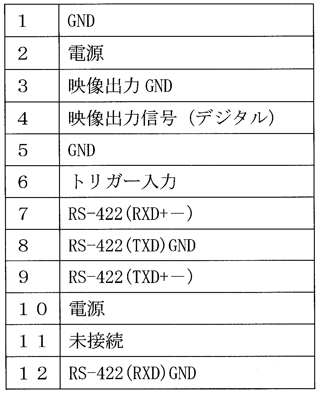
ところで、従来のアナログ方式のカメラケーブルは、表1にケーブルピンアサインの一例を示すように、映像信号、HD信号、VD信号、トリガー信号の4系統の信号の送受信に対応しなければならなかった。そして、カメラヘッドユニットをデジタル方式にするためには制御通信用信号(ゲインやシャッター速度などのカメラヘッドユニットの属性を制御するための信号。RS422)のための2系統の信号送信が必要になるが、本発明においては、上述の画像メモリ部12と映像信号書き換え部13と映像信号読み出し部14とによってデジタル映像信号の受信タイミングに依存しないタイミングでアナログ映像信号を前記外部機器3に出力することができるので、従来のアナログ方式のカメラシステムで必要であったHD信号やVD信号の受信は不要となる(表2参照)。その結果、HD信号やVD信号のための信号線を制御通信用信号(RS422)の送信に利用することが可能となり、カメラケーブルは従来のもの(アナログ方式のカメラシステムで使用していたもの)をそのまま使用できることとなる。このことによっても、段階的な設備投資でデジタル化を図ることができる。

本発明に係るカメラシステムは、
・ 上述の構成のカメラコントロールユニット1と、
・ 前記カメラケーブル接続部10に接続されるカメラケーブル4と、
・ 該カメラケーブル4に接続されるデジタル方式のカメラヘッドユニット2と、
・ 前記外部機器接続部11に外部機器用ケーブル5を介して接続される外部機器3と、
からなる。
・ 上述の構成のカメラコントロールユニット1と、
・ 前記カメラケーブル接続部10に接続されるカメラケーブル4と、
・ 該カメラケーブル4に接続されるデジタル方式のカメラヘッドユニット2と、
・ 前記外部機器接続部11に外部機器用ケーブル5を介して接続される外部機器3と、
からなる。
1 カメラコントロールユニット
2 カメラヘッドユニット
3 外部機器
4 カメラケーブル
5 外部機器用ケーブル
10 カメラケーブル接続部
11 外部機器接続部
12 画像メモリ部
12A,12B,… 保存領域
13 映像信号書き換え部
14 映像信号読み出し部
15 D/A変換部
SD デジタル映像信号
SS 同期信号
2 カメラヘッドユニット
3 外部機器
4 カメラケーブル
5 外部機器用ケーブル
10 カメラケーブル接続部
11 外部機器接続部
12 画像メモリ部
12A,12B,… 保存領域
13 映像信号書き換え部
14 映像信号読み出し部
15 D/A変換部
SD デジタル映像信号
SS 同期信号
Claims (3)
- カメラヘッドユニットからの映像信号を処理して外部機器に伝送するカメラコントロールユニットにおいて、
デジタル方式のカメラヘッドユニットに接続されたカメラケーブルを接続できるカメラケーブル接続部と、
前記外部機器を接続できる外部機器接続部と、
複数の保存領域を有して、前記カメラヘッドユニットからのデジタル映像信号を画像別に保存する画像メモリ部と、
該複数の保存領域の内、一番古い画像のデジタル映像信号が保存されている領域に、前記カメラヘッドユニットから送られて来た最新のデジタル映像信号を書き換え保存する映像信号書き換え部と、
前記外部機器からの同期信号に基づいて、前記複数の保存領域から一番新しい画像のデジタル映像信号を読み出す映像信号読み出し部と、
該映像信号読み出し部により読み出されたデジタル映像信号をアナログ映像信号に変換するD/A変換部と、
該変換されたアナログ映像信号を前記外部機器からの同期信号に基づいたタイミングで該外部機器に送信する映像信号送信部と、
を備えたことを特徴とするカメラコントロールユニット。 - 前記外部機器はキャプチャーボード又はモニターである、
ことを特徴とする請求項1に記載のカメラコントロールユニット。 - 請求項1又は2に記載のカメラコントロールユニットと、
前記カメラケーブル接続部に接続されるカメラケーブルと、
該カメラケーブルに接続されるデジタル方式のカメラヘッドユニットと、
前記外部機器接続部に外部機器用ケーブルを介して接続される外部機器と、
を備えたカメラシステム。
Applications Claiming Priority (2)
| Application Number | Priority Date | Filing Date | Title |
|---|---|---|---|
| JP2010021909A JP2011160321A (ja) | 2010-02-03 | 2010-02-03 | カメラコントロールユニット、及び該カメラコントロールユニットを備えたカメラシステム |
| JP2010-021909 | 2010-02-03 |
Publications (1)
| Publication Number | Publication Date |
|---|---|
| WO2011096254A1 true WO2011096254A1 (ja) | 2011-08-11 |
Family
ID=44355264
Family Applications (1)
| Application Number | Title | Priority Date | Filing Date |
|---|---|---|---|
| PCT/JP2011/050337 Ceased WO2011096254A1 (ja) | 2010-02-03 | 2011-01-12 | カメラコントロールユニット、及び該カメラコントロールユニットを備えたカメラシステム |
Country Status (2)
| Country | Link |
|---|---|
| JP (1) | JP2011160321A (ja) |
| WO (1) | WO2011096254A1 (ja) |
Citations (4)
| Publication number | Priority date | Publication date | Assignee | Title |
|---|---|---|---|---|
| JPH06178149A (ja) * | 1992-12-09 | 1994-06-24 | Matsushita Electric Ind Co Ltd | 映像復号化装置 |
| JPH08125903A (ja) * | 1994-10-27 | 1996-05-17 | Toshiba Corp | テレビジョンカメラ装置 |
| JP2001346076A (ja) * | 2000-06-05 | 2001-12-14 | Victor Co Of Japan Ltd | 撮像装置 |
| JP2009128681A (ja) * | 2007-11-26 | 2009-06-11 | Olympus Corp | 側視用アタッチメント及び内視鏡装置 |
-
2010
- 2010-02-03 JP JP2010021909A patent/JP2011160321A/ja active Pending
-
2011
- 2011-01-12 WO PCT/JP2011/050337 patent/WO2011096254A1/ja not_active Ceased
Patent Citations (4)
| Publication number | Priority date | Publication date | Assignee | Title |
|---|---|---|---|---|
| JPH06178149A (ja) * | 1992-12-09 | 1994-06-24 | Matsushita Electric Ind Co Ltd | 映像復号化装置 |
| JPH08125903A (ja) * | 1994-10-27 | 1996-05-17 | Toshiba Corp | テレビジョンカメラ装置 |
| JP2001346076A (ja) * | 2000-06-05 | 2001-12-14 | Victor Co Of Japan Ltd | 撮像装置 |
| JP2009128681A (ja) * | 2007-11-26 | 2009-06-11 | Olympus Corp | 側視用アタッチメント及び内視鏡装置 |
Also Published As
| Publication number | Publication date |
|---|---|
| JP2011160321A (ja) | 2011-08-18 |
Similar Documents
| Publication | Publication Date | Title |
|---|---|---|
| EP2037673A1 (en) | Solid-state image pickup device, data transmitting method and image pickup device | |
| JP2008145902A (ja) | マルチスクリーン表示装置 | |
| JP2009010537A5 (ja) | ||
| RU2009117330A (ru) | Система передачи данных, передатчик, приемник, способ передачи данных, программа и кабель для передачи данных | |
| CN104918003A (zh) | 多摄像机同步系统 | |
| KR101459753B1 (ko) | 원 보드타입의 듀얼 카메라모듈 | |
| US20120293676A1 (en) | Head-separated camera device | |
| JP4922190B2 (ja) | 画像形成装置および画像形成方法 | |
| US20110050877A1 (en) | Head separated camera apparatus | |
| KR101299003B1 (ko) | 스마트폰을 이용한 실시간 영상확인장치 | |
| WO2011096254A1 (ja) | カメラコントロールユニット、及び該カメラコントロールユニットを備えたカメラシステム | |
| JP2010152867A (ja) | センサ信号変換装置 | |
| US20160105618A1 (en) | Information processing device, information processing method, program, and information processing system | |
| US9218050B2 (en) | Method and device for transmitting/receiving image data at high speed | |
| JP4752567B2 (ja) | 映像伝送システム | |
| JP5423071B2 (ja) | データ転送装置及び撮像装置 | |
| JP2008219223A (ja) | 監視システム | |
| JP6414702B2 (ja) | 画像処理装置 | |
| JP5111254B2 (ja) | 遠隔測定処理システム及び遠隔測定処理方法 | |
| JP4700563B2 (ja) | データ伝送方法およびデータ伝送システム | |
| JP2008131264A (ja) | 監視カメラ、画像記録表示装置及び監視カメラシステム | |
| KR100320151B1 (ko) | 다중 영상신호저장 제어장치 | |
| JP3688105B2 (ja) | 映像切換装置およびこの映像切換装置を使用した映像切換設備 | |
| CN214675325U (zh) | 一种图像采集系统 | |
| JP2002169770A (ja) | 画像データ転送システム |
Legal Events
| Date | Code | Title | Description |
|---|---|---|---|
| 121 | Ep: the epo has been informed by wipo that ep was designated in this application |
Ref document number: 11739603 Country of ref document: EP Kind code of ref document: A1 |
|
| NENP | Non-entry into the national phase |
Ref country code: DE |
|
| 122 | Ep: pct application non-entry in european phase |
Ref document number: 11739603 Country of ref document: EP Kind code of ref document: A1 |