WO2011086876A1 - シリコンウェーハの表面浄化方法 - Google Patents
シリコンウェーハの表面浄化方法 Download PDFInfo
- Publication number
- WO2011086876A1 WO2011086876A1 PCT/JP2011/000022 JP2011000022W WO2011086876A1 WO 2011086876 A1 WO2011086876 A1 WO 2011086876A1 JP 2011000022 W JP2011000022 W JP 2011000022W WO 2011086876 A1 WO2011086876 A1 WO 2011086876A1
- Authority
- WO
- WIPO (PCT)
- Prior art keywords
- acid
- wafer
- gas
- silicon wafer
- cleaning
- Prior art date
- Legal status (The legal status is an assumption and is not a legal conclusion. Google has not performed a legal analysis and makes no representation as to the accuracy of the status listed.)
- Ceased
Links
Images


Classifications
-
- H—ELECTRICITY
- H10—SEMICONDUCTOR DEVICES; ELECTRIC SOLID-STATE DEVICES NOT OTHERWISE PROVIDED FOR
- H10P—GENERIC PROCESSES OR APPARATUS FOR THE MANUFACTURE OR TREATMENT OF DEVICES COVERED BY CLASS H10
- H10P70/00—Cleaning of wafers, substrates or parts of devices
- H10P70/10—Cleaning before device manufacture, i.e. Begin-Of-Line process
- H10P70/15—Cleaning before device manufacture, i.e. Begin-Of-Line process by wet cleaning only
-
- H—ELECTRICITY
- H10—SEMICONDUCTOR DEVICES; ELECTRIC SOLID-STATE DEVICES NOT OTHERWISE PROVIDED FOR
- H10P—GENERIC PROCESSES OR APPARATUS FOR THE MANUFACTURE OR TREATMENT OF DEVICES COVERED BY CLASS H10
- H10P70/00—Cleaning of wafers, substrates or parts of devices
- H10P70/10—Cleaning before device manufacture, i.e. Begin-Of-Line process
- H10P70/12—Cleaning before device manufacture, i.e. Begin-Of-Line process by dry cleaning only
- H10P70/125—Cleaning before device manufacture, i.e. Begin-Of-Line process by dry cleaning only with gaseous HF
Definitions
- the present invention relates to a method for cleaning the surface of a silicon wafer, and more particularly, to a method for cleaning a surface suitable for removing fine particles such as organic substances and metals adhering to the surface of a silicon wafer.
- the wafer is cleaned before and after various manufacturing processes.
- various manufacturing processes For example, before the epitaxial growth treatment, in order to remove silica abrasive grains remaining in the polishing process and fine particles such as organic substances adhering from the apparatus, single wafer cleaning is repeatedly performed using ozone water and hydrofluoric acid water. Is going.
- ozone water and hydrofluoric acid water are alternately supplied to the surface of the wafer while rotating the wafer, and fine particles such as organic substances and metals adhering to the wafer surface are cleaned and removed together with a chemical solution.
- Patent Document 1 that uses an oxidizing gas to form an oxide film
- an organic solvent vapor and water vapor are brought into contact with the wafer to form a liquid film on the wafer.
- the molecules of the etching gas do not penetrate evenly into the liquid film, the etching does not proceed uniformly in the surface, and there is a problem that the fine particles are not separated (lifted off) from the wafer efficiently.
- the object of the present invention made by paying attention to these points is silicon that can remove fine particles such as organic matter and metal adhering to the wafer surface with less residual fine particles with a small amount of chemical solution used.
- An object of the present invention is to provide a wafer surface cleaning method.
- a method for cleaning the surface of a silicon wafer according to the present invention that achieves the above object, A first surface layer reforming step in which an oxidizing gas is brought into contact with the surface of the silicon wafer, and the surface layer including the wafer surface is used as a first oxide film; A surface layer removing step of contacting the wafer surface with an etching gas to remove the first oxide film; A second surface layer modification treatment step of contacting a chemical solution having an oxidizing action with the wafer surface from which the first oxide film has been removed to remove fine particles remaining on the wafer surface and to form a second oxide film; It is characterized by having.
- the gas having an oxidizing action is preferably ozone gas.
- the gas having an etching action is preferably a hydrogen fluoride-containing gas.
- the hydrogen fluoride-containing gas contains methanol, ethanol, or isopropyl alcohol vapor, or citric acid gas or oxalic acid gas, or methanol, ethanol, or isopropyl alcohol vapor. It is preferable to contain either of these, citric acid gas, or oxalic acid gas.
- the chemical solution having an oxidizing action is preferably ozone water or hydrogen peroxide water.
- an organic acid rinsing step for cleaning the wafer surface using an organic acid chemical solution to remove metal particles between the surface layer removing step and the second surface layer modifying treatment step.
- an oxidizing gas is brought into contact with the wafer surface, the surface layer including the wafer surface is used as the first oxide film, and then an etching gas is brought into contact with the wafer surface to Since the oxide film is removed, and the fine particles remaining on the wafer surface are removed and the second oxide film is formed using an oxidizing chemical solution, the wafer surface can be used with a small amount of chemicals used. Fine particles such as organic substances and metals adhering to the surface can be removed so that there are fewer residual fine particles.
- FIG. 1 It is a block diagram which shows schematic structure of the washing
- FIG. 1 is a block diagram showing a schematic configuration of a cleaning apparatus used when performing a method according to an embodiment of the present invention.
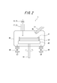
- FIG. 2 is a schematic configuration diagram of the cleaning apparatus main body of FIG.
- the wafer cleaning apparatus 10 includes a sealable single wafer cleaning apparatus main body 11 loaded with a polished wafer, a first gas supply pipe system 12 for supplying ozone gas, and a cleaning apparatus main body.
- a second gas supply pipe system 13 for supplying nitrogen gas or a mixed gas of nitrogen gas and hydrogen fluoride gas and / or organic solvent vapor, and ozone water, an organic acid chemical solution, or pure water Liquid supply pipe system 14.
- the first gas supply pipe system 12 includes an ozone gas supply unit 16, a pipe 17 that connects the ozone gas supply unit 16 and the cleaning apparatus main body 11, and a flow rate regulator 18 that is disposed in the pipe 17.
- the second gas supply pipe system 13 includes a nitrogen gas supply unit 20, a hydrogen fluoride gas supply unit 21, and an organic solvent vapor supply unit 22.
- the nitrogen gas supply unit 20 is connected to the cleaning device main body 11 via a pipe 23, and an opening / closing valve 24 and a flow rate regulator are provided at the original parts of the pipe 23 on the nitrogen gas supply unit 20 and the cleaning device main body 11 side. 25 is arranged. Between the on-off valve 24 and the flow rate regulator 25 of the pipe 23, the other end of the pipe 26 and the pipe 27, one end of which is connected to the hydrogen fluoride gas supply unit 21 and the organic solvent vapor supply unit 22, is connected. Yes. Further, the pipe 26 and the pipe 27 are provided with an on-off valve 28 and an on-off valve 29, respectively.
- the liquid supply pipe system 14 includes a pipe 31, an organic acid chemical liquid supply unit 32, an ozone water supply unit 33, and a pure water supply unit 34.
- One end of the pipe 31 communicates with a nozzle in the cleaning apparatus main body 11, and the other end portion branches into three and is connected to an organic acid chemical solution supply unit 32, an ozone water supply unit 33, and a pure water supply unit 34, respectively. Is done.
- flow rate regulators 35, 36, and 37 are disposed at the three branches of the pipe 31, respectively.
- the cleaning processing chamber 40 in the cleaning apparatus main body 11 has a stage 42 for loading a wafer 41 as shown in FIG.
- the stage 42 includes a wafer support portion 43 that supports the wafer 41 at its end surface, and a shaft 44 that extends downward from the lower center of the stage.
- the shaft 44 is connected to a rotary motor (not shown), and the stage 42 can be rotated at an arbitrary speed by rotational driving of the motor.
- the piping 17 communicates with the cleaning processing chamber 40 through the flow rate regulator 18, ozone gas is supplied from the first gas supply pipe system 12, the piping 23 communicates with the flow rate regulator 25, and the second Nitrogen gas, hydrogen fluoride gas, and organic solvent vapor are supplied from the gas supply pipe system 13.
- a tip of a nozzle 45 connected to the pipe 31 is provided above the wafer 41 in the cleaning processing chamber 40, and ozone water and organic are supplied from the liquid system supply pipe system 14 via the flow rate regulator 35, 36 or 37.
- An acid chemical solution or pure water is supplied to the upper surface of the wafer.
- an exhaust pipe 47 for exhausting exhaust gas through an on-off valve 46 and a waste liquid pipe 49 for exhausting waste liquid through an on-off valve 48 communicate with the lower part of the cleaning processing chamber 40.
- FIG. 3 is a flowchart showing a procedure for carrying out the wafer surface purification method according to the present embodiment.
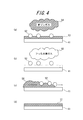
- FIG. 4 is a view for explaining the principle of surface cleaning of a silicon wafer by the method of the present invention.
- FIGS. 4 (a) to 4 (d) are vertical sectional views of a part of the silicon wafer at a predetermined stage of the cleaning process.
- FIG. 4 (a) to 4 (d) are vertical sectional views of a part of the silicon wafer at a predetermined stage of the cleaning process.
- the silicon wafer surface purification method of the present embodiment is performed according to the following procedure. First, the silicon wafer 41 to be cleaned is loaded on the stage 42 in the chamber of the wafer cleaning apparatus 10. Next, the flow rate regulator 18 is operated to introduce ozone gas, which is an oxidizing gas, into the cleaning apparatus body 11 from the ozone gas supply unit 16 through the pipe 17, and this is brought into contact with the surface of the wafer 41. A first surface layer reforming process for forming an oxide film (first oxide film) on the surface layer including the wafer surface is performed (step S1).
- ozone gas which is an oxidizing gas
- the surface layer including the surface of the silicon wafer 41 to which the fine particles 52 are fixed becomes the oxide film 53 which is the first oxide film.
- the ozone gas 54 which is a gas, circulates below the fine particles 52, an oxide film is also formed below the fine particles 52.
- the concentration when ozone gas is used as the oxidizing gas is preferably 50 to 300 g / m 3.
- concentration of ozone gas is lower than 50 g / m 3, an oxide film having a sufficient thickness is not formed on the wafer surface, and when it is higher than 300 g / m 3, the surface state may be deteriorated.
- the time for supplying ozone gas to the wafer cleaning apparatus is preferably 5 seconds or more. If the gas supply time is shorter than 5 seconds, an oxide film having a sufficient thickness may not be formed on the wafer surface.
- the ozone gas is cleaned through the exhaust pipe 47 by operating the on-off valve 24 and the flow rate regulator 25 to introduce nitrogen gas into the cleaning processing chamber 40 from the nitrogen gas supply unit 20 through the pipe 23.
- the gas is discharged from the processing chamber 40.
- a hydrogen fluoride-containing gas which is an etching gas, is introduced from the hydrogen fluoride gas supply unit 21 through the pipes 26 and 23 into the cleaning processing chamber 40 and is brought into contact with the surface of the silicon wafer 41.
- a surface layer removing step is performed to remove the oxide film on the wafer by etching (step S2). As a result, the fine particles 52 are separated (lifted off) from the silicon wafer 41 as shown in FIG.
- An anhydrous hydrogen fluoride gas is preferably used as the gas having an etching action.
- Hydrogen fluoride gas is mixed with nitrogen gas and supplied, and the gas concentration is preferably 1000 to 400,000 ppm.
- the gas concentration of the hydrogen fluoride gas is lower than 1000 ppm, the oxide film on the wafer surface is not easily etched, and when it is higher than 400000 ppm, the corrosivity becomes high.
- the ppm at this time represents a volume ratio, and 10000 ppm is 1 vol%.
- the time for supplying the hydrogen fluoride gas to the wafer cleaning apparatus is preferably 10 seconds or more. If the gas supply time is shorter than 10 seconds, it is difficult to sufficiently remove the oxide film on the wafer surface by etching.
- the drying effect can be enhanced by adding methanol, ethanol, or isopropyl alcohol vapor to the hydrogen fluoride gas.
- the hydrogen fluoride-containing gas contains citric acid gas or oxalic acid gas. By doing so, the potential of the fine particles 52 is stabilized, and the removal effect of the fine particles 52 can be enhanced.
- These organic solvent gases are supplied from the organic solvent vapor supply unit 22 to the cleaning processing chamber 40 via the pipes 27 and 23.
- step S3 the organic acid chemical solution supply unit 32 passes the pipe 31 and the nozzle 45 to the silicon wafer 41.
- a wafer surface rinsing process is performed by supplying an organic acid chemical (step S3). This prevents re-adhesion of the fine particles and removes the metal particles.
- Organic acid chemicals include oxalic acid, citric acid, succinic acid, ethylenediaminetetraacetic acid, tartaric acid, salicylic acid, formic acid, maleic acid, propionic acid, acetic acid, butyric acid, valeric acid, caproic acid, enanthic acid, caprylic acid, benzoic acid It is preferable to use acrylic acid, adipic acid, malonic acid, malic acid, glycolic acid, phthalic acid, terephthalic acid or fumaric acid. In particular, from the viewpoint of improving the removal effect of the metal particles on the wafer surface, it is desirable to use a non-ionic dicarboxylic acid having a potential, and it is preferable to use oxalic acid or citric acid.
- the rinsing step on the wafer surface using a chemical solution of an organic acid can be omitted. Even without this step, the fine particles from the silicon wafer 41 can be removed by the next second surface layer reforming step.
- the organic acid rinsing step it becomes possible to more effectively enhance the removal action of the metal fine particles from the wafer surface due to the chelating effect of the organic acid.
- step S4 nitrogen gas is introduced into the cleaning processing chamber 40 from the nitrogen gas supply unit 20 through the pipe 23, and the hydrogen fluoride-containing gas is discharged from the cleaning processing chamber 40 through the exhaust pipe 47.
- the second surface layer that supplies ozone water which is a chemical solution having an oxidizing action, from the ozone water supply unit 33 to the silicon wafer 41 through the pipe 31 and the nozzle 45.
- a reforming process is performed (step S4).
- the surface of the wafer was cleaned by supplying ozone water 56 onto the wafer 41, and the fine particles 52 remaining on the silicon wafer 41 after Step 3 or Step 3 was omitted.
- the fine particles 52 separated from the silicon wafer 41 in step S2 are removed from the surface of the silicon wafer 41, and a second oxide film is formed on the surface layer portion of the silicon wafer 41 as shown in FIG. An oxide film 57 is formed.
- the concentration of ozone water is lower than 0.5 ppm, the ozone aqueous solution used as a chemical solution having an oxidizing action is difficult to remove fine particles sufficiently, and the solubility limit of ozone in pure water is about 25 ppm. It is desirable that the water concentration is 0.5 to 25 ppm.
- the ppm at this time represents a weight ratio, and 10000 ppm is 1 wt%.
- step S5 pure water is supplied onto the silicon wafer 41 from the pure water supply unit 34 via the pipe 31 and the nozzle 45 while rotating the silicon wafer 41 in the cleaning processing chamber 40. Then, a rinsing process for cleaning the wafer surface is performed (step S5). Thereafter, a drying process for drying the wafer is performed by increasing the rotational speed of the silicon wafer 41, shaking off pure water by centrifugal force, and heating the temperature in the cleaning chamber 40 (step S6). In addition, the rinse process of step S5 can be omitted.
- the surface layer including the wafer surface is oxidized with ozone gas having an oxidizing action, and the oxide film is etched with a hydrogen fluoride-containing gas having an etching action, whereby a liquid is obtained.
- the protective film can be formed on the wafer surface by simultaneously removing the fine particles separated from the wafer surface and making the wafer surface hydrophilic using ozone water having an oxidizing action.
- the amount of chemical solution and pure water used can be reduced, and the cost for the cleaning step can be reduced. Furthermore, by cleaning the wafer surface with a chemical solution of an organic acid between the surface layer removal step and the second surface layer modification treatment step, the metal fine particles can be more effectively removed.
- the present invention is not limited to the above embodiment, and many changes or modifications can be made.
- wafer cleaning is performed using a single wafer cleaning apparatus, but the present invention is not limited to this and can be applied to a batch cleaning apparatus.
- ozone gas is used as the gas having an oxidizing action
- the gas is not limited thereto
- the gas having an etching action is a hydrogen fluoride-containing gas, but is not limited thereto.
- ozone water is used as the chemical solution having an oxidizing action, it is not limited to this, and hydrogen peroxide water or the like can also be used.
- Example 1 the processing conditions of the steps S1, S2, and S4 are set as follows, and steps S1, S2, S4-S6 are performed to perform surface purification of a wafer having a diameter of 300 mm without performing step S3. went.
- Step 1 First surface layer reforming process
- Gas used Ozone gas Wafer temperature: 25 ° C
- Step 2 Surface layer removal process
- Gas used Hydrogen fluoride gas Wafer temperature: 25 ° C Concentration of hydrogen fluoride gas: 10000 ppm (1 vol%) (remainder N2) Gas supply time: 15 seconds
- Step 4 Second surface layer modification treatment process
- Chemical solution used Ozone water Wafer temperature: 25 ° C Concentration of ozone water: 10ppm (0.001wt%) Liquid supply time: 30 seconds
- Example 2 The surface layer of the wafer was purified under the condition that the hydrogen fluoride gas in the surface layer removing step of Step 2 of Example 1 was replaced with anhydrous hydrogen fluoride gas.
- the concentration of anhydrous hydrogen fluoride gas was 1 vol%.
- Other conditions were the same as in Example 1.
- Example 3 The surface of the wafer was cleaned by replacing the hydrogen fluoride gas in the surface layer removal step of Step 2 of Example 1 with a mixed gas of hydrogen fluoride gas and isopropyl alcohol vapor.
- the concentration of the mixed gas at this time was 15000 ppm.
- Other conditions were the same as in Example 1.
- Example 4 As a chemical solution having an oxidizing action in Step 4 of Example 1, the wafer surface was purified using hydrogen peroxide water instead of ozone water. The concentration of the hydrogen peroxide solution at this time was 3 wt%. Other conditions were the same as in Example 1.
- Example 5 The wafer surface was cleaned by adding the organic acid rinsing process of Step 3 between Step 2 and Step 4 of Example 1. Other conditions were the same as in Example 1. As the organic acid chemical used, oxalic acid having a concentration of 0.05 wt% was used.
- Example 1-5 an excellent fine particle removal effect was obtained compared to Comparative Examples 1 and 2. Furthermore, in Example 5 including the organic acid rinsing step, an excellent metal fine particle removing effect was obtained as compared with Example 1.
- an oxidizing gas is brought into contact with the wafer surface, the surface layer including the wafer surface is used as the first oxide film, and then an etching gas is brought into contact with the wafer surface to Since the oxide film is removed, and the fine particles remaining on the wafer surface are removed and the second oxide film is formed using an oxidizing chemical solution, the wafer surface can be used with a small amount of chemicals used. Fine particles such as organic substances and metals adhering to the surface can be removed so that there are fewer residual fine particles.
Landscapes
- Cleaning Or Drying Semiconductors (AREA)
Abstract
オゾンガスをウェーハ表面に接触させ、ウェーハ表面に酸化膜を形成させ(ステップS1)、フッ化水素ガスをウェーハ表面に接触させ、ウェーハ表面に形成された酸化膜を除去し(ステップS2)、シュウ酸またはクエン酸のジカルボン酸の薬液を用いてウェーハ表面を洗浄し、微粒子の再付着防止と金属粒子の除去とを行い(ステップS3)、さらに、オゾン水を用いてウェーハ表面を洗浄して微粒子を除去するとともに、更なる酸化膜の形成を行う(ステップS4)。これにより、少ない薬品の使用量で、ウェーハ表面に付着した有機物および金属等の微粒子をより精度高く除去することができるシリコンウェーハの表面浄化方法を提供する。
Description
本出願は、2010年1月13日に出願された日本国特許出願2010-4801号の優先権を主張するものであり、この先の出願の開示全体をここに参照のために取り込む。
本発明は、シリコンウェーハの表面浄化方法に関し、特に、シリコンウェーハ表面に付着した有機物および金属等の微粒子を除去するのに好適な表面浄化方法に関する。
シリコンウェーハ(以下、「ウェーハ」とも呼ぶ)の製造工程では、種々の製造プロセスの前後でウェーハの洗浄を行う。例えば、エピタキシャル成長処理前には、研磨工程で残留したシリカの砥粒や装置から付着した有機物等の微粒子を除去するために、枚葉洗浄として、オゾン水とフッ酸水とを用いて繰り返し洗浄を行っている。この表面浄化方法は、ウェーハを回転させながらウェーハの表面にオゾン水とフッ酸水とを交互に供給し、ウェーハ表面に付着した有機物や金属などの微粒子を薬液とともに洗浄除去するものである。
また、酸化性ガスをウェーハに接触させてウェーハ表面上に酸化膜を形成し、その後、ウェーハを有機溶剤蒸気と水蒸気との混合蒸気に接触させて、ウェーハ上に混合蒸気の液膜を形成した状態で、エッチングガスをウェーハに接触させて酸化膜をエッチングして除去することによって、ウェーハを洗浄する方法が提案されている(例えば、特許文献1参照)。
しかしながら、オゾン水とフッ酸水とを用いた従来の表面浄化方法では、液体の有する表面張力のために、ウェーハ表面に存在する微小な凹部の中や微粒子の裏側まで薬液が入り込むことができず、付着した微粒子、特に、小さいサイズの粒子の除去が不十分であった。また、ウェーハ表面を清浄化するには相当量の薬液が必要となり、高コストになるという問題点があった。
また、酸化膜を形成するために酸化性ガスを用いる特許文献1に記載の方法では、酸化膜を除去する工程の前に、有機溶剤蒸気と水蒸気とをウェーハに接触させてウェーハ上に液膜を形成する。しかし、エッチングガスの分子は液膜内に均等に浸透しないため、エッチングが面内均一に進行せず、微粒子のウェーハからの離間(リフトオフ)が効率的に行われないという問題点を有する。
したがって、これらの点に着目してなされた本発明の目的は、少ない薬液の使用量で、ウェーハ表面に付着した有機物および金属等の微粒子をより残留微粒子が少なくなるように除去することができるシリコンウェーハの表面浄化方法を提供することにある。
上記目的を達成する本発明に従うシリコンウェーハの表面浄化方法は、
酸化作用のあるガスをシリコンウェーハの表面に接触させて、該ウェーハ表面を含む表層を第1の酸化膜とする第1表層改質処理工程と、
エッチング作用のあるガスを前記ウェーハ表面に接触させて、前記第1の酸化膜を除去する表層除去工程と、
酸化作用のある薬液を、前記第1の酸化膜を除去したウェーハ表面に接触させて該ウェーハ表面に残存する微粒子の除去と第2の酸化膜の形成を行う第2表層改質処理工程と
を有することを特徴とするものである。
酸化作用のあるガスをシリコンウェーハの表面に接触させて、該ウェーハ表面を含む表層を第1の酸化膜とする第1表層改質処理工程と、
エッチング作用のあるガスを前記ウェーハ表面に接触させて、前記第1の酸化膜を除去する表層除去工程と、
酸化作用のある薬液を、前記第1の酸化膜を除去したウェーハ表面に接触させて該ウェーハ表面に残存する微粒子の除去と第2の酸化膜の形成を行う第2表層改質処理工程と
を有することを特徴とするものである。
上述のシリコンウェーハの表面浄化方法においては、酸化作用のあるガスは、オゾンガスであることが好ましい。
上述のエッチング作用のあるガスは、フッ化水素含有ガスであることが好ましい。さらに、フッ化水素含有ガスに、メタノール、エタノール、または、イソプロピルアルコールの蒸気などを含有させる、あるいはクエン酸ガス、または、シュウ酸ガスを含有させる、あるいは、メタノール、エタノール、または、イソプロピルアルコールの蒸気のいずれかと、クエン酸ガス、または、シュウ酸ガスのいずれかを含有させることが好適である。
また、酸化作用のある薬液は、オゾン水または過酸化水素水であることが好ましい。
さらに、本発明の実施形態としては、第2表層改質処理工程に続いて、純水によりシリコンウェーハを洗浄する純水リンス工程と洗浄したシリコンウェーハを乾燥させる乾燥工程とをさらに有することが好ましい。
また、表層除去工程と第2表層改質処理工程との間に、有機酸の薬液を用いてウェーハ表面を洗浄し、金属粒子の除去を行う有機酸リンス工程をさらに有することが好ましく、有機酸の薬液は、シュウ酸、クエン酸、コハク酸、エチレンジアミン四酢酸、酒石酸、サリチル酸、ギ酸、マレイン酸、プロピオン酸、酢酸、酪酸、吉草酸、カプロン酸、エナント酸、カプリル酸、安息香酸、アクリル酸、アジピン酸、マロン酸、リンゴ酸、グリコール酸、フタル酸、テレフタル酸あるいはフマル酸であることが好適である。
本発明によれば、酸化作用のあるガスをウェーハ表面に接触させて、該ウェーハ表面を含む表層を第1の酸化膜とし、次いで、エッチング作用のあるガスをウェーハ表面に接触させて、第1の酸化膜を除去し、さらに、酸化作用のある薬液を用いてウェーハ表面に残留する微粒子の除去と、第2の酸化膜の形成を行うようにしたので、少ない薬品の使用量で、ウェーハ表面に付着した有機物および金属等の微粒子をより残留微粒子が少なくなるように除去することができる。
以下、本発明の一実施の形態について、図1~図4を参照して説明する。
先ず、図1および図2を参照して、本発明の洗浄方法を適用する際に使用する洗浄装置の構成を説明する。図1は、本発明の一実施の形態に係る方法を実施する際に使用する洗浄装置の概略構成を示すブロック図である。また、図2は、図1の洗浄装置本体の概略構成図である。
ウェーハ洗浄装置10は、図1に示すように、研磨後のウェーハが装填される密閉可能な枚葉式の洗浄装置本体11と、オゾンガスを供給する第1ガス供給管系12と、洗浄装置本体11に窒素ガスまたは窒素ガスとフッ化水素ガスおよび/もしくは有機溶剤蒸気との混合ガスを供給するための第2ガス供給管系13と、オゾン水、有機酸薬液、または純水を供給するための液系供給管系14とを備える。
第1ガス供給管系12は、オゾンガス供給部16、オゾンガス供給部16と洗浄装置本体11とを連結する配管17、および、配管17に配設された流量調節器18を備える。
また、第2ガス供給管系13は、窒素ガス供給部20とフッ化水素ガス供給部21と有機溶剤蒸気供給部22とを有する。窒素ガス供給部20は、配管23を介して洗浄装置本体11と接続しており、配管23の窒素ガス供給部20および洗浄装置本体11側のそれぞれの元部には開閉弁24および流量調節器25が配設されている。配管23の開閉弁24および流量調節器25の間には、それぞれ、一端がフッ化水素ガス供給部21および有機溶剤蒸気供給部22に接続された配管26および配管27の他端が接続されている。さらに、配管26および配管27には、それぞれ開閉弁28および開閉弁29が設けられている。
また、液系供給管系14は、配管31、有機酸薬液供給部32、オゾン水供給部33および純水供給部34を備える。配管31は一端が洗浄装置本体11内のノズルに連通し、他方の端部側は3つに分岐してそれぞれ、有機酸薬液供給部32、オゾン水供給部33および純水供給部34に接続される。さらに、配管31の3つに分岐した部分には、それぞれ、流量調節器35、36および37が配設されている。
洗浄装置本体11内の洗浄処理チャンバ40は、図2に示すように、ウェーハ41を装填するためのステージ42を有する。ステージ42は、ウェーハ41を端面で支持するウェーハ支持部43と、ステージの下部中央から下方へ延びるシャフト44を有する。シャフト44は図示しない回転モータに接続され、該モータの回転駆動によりステージ42を任意の速度で回転させることができる。また、洗浄処理チャンバ40には、流量調節器18を介して配管17が連通し、第1ガス供給管系12よりオゾンガスが供給され、流量調節器25を介して配管23が連通し、第2ガス供給管系13より窒素ガス、フッ化水素ガス、有機溶剤蒸気が供給される。さらに、洗浄処理チャンバ40内のウェーハ41の上方には配管31に接続されたノズル45の先端が設けられ、流量調節器35、36または37を介して液系供給管系14よりオゾン水、有機酸薬液、または、純水をウェーハ上面に供給する。また、洗浄処理チャンバ40の下部には、開閉弁46を介して排ガスを排気する排気管47と、開閉弁48を介して廃液を排出する廃液管49が連通している。
次に、図1、図2に加え、図3および図4を参照して、本発明に係るウェーハ表面浄化方法を説明する。図3は、本実施の形態に係るウェーハ表面浄化方法を実施する際の手順を示すフローチャートである。また、図4は、本発明の方法によるシリコンウェーハの表面浄化原理を説明する図であり、図4(a)-(d)は、洗浄処理の所定の段階におけるシリコンウェーハの一部の垂直断面図である。
本実施の形態のシリコンウェーハの表面浄化方法は、以下の手順に従って実施する。先ず、ウェーハ洗浄装置10のチャンバ内のステージ42に洗浄対象のシリコンウェーハ41を装填する。次に、流量調節器18を操作して、配管17を介してオゾンガス供給部16から酸化作用のあるガスであるオゾンガスを洗浄装置本体11内に導入し、これをウェーハ41の表面に接触させ、該ウェーハ表面を含む表層に酸化膜(第1の酸化膜)を形成する第1表層改質処理工程を行う(ステップS1)。
図4(a)に示すように、第1表層改質処理後には、微粒子52が固着しているシリコンウェーハ41の表面を含む表層が、第1の酸化膜である酸化膜53となっている。気体であるオゾンガス54が微粒子52の下側に回り込むことによって、微粒子52の下側にも酸化膜が形成されている。
酸化作用のあるガスにオゾンガスを用いる場合の濃度は、好ましくは、50~300g/m3である。オゾンガスの濃度が50g/m3より低いと、ウェーハ表面上に十分な厚さの酸化膜が形成されず、300g/m3より高いと表面状態の悪化に繋がる恐れがある。また、ウェーハ洗浄装置にオゾンガスを供給する時間は、好ましくは、5秒以上である。ガス供給時間を5秒より短くすると、ウェーハ表面上に十分な厚さの酸化膜が形成できない恐れがある。ここで、次工程のエッチング工程時における微粒子とウェーハとの離間距離を確保する観点から、10Å以上の酸化膜を形成することが望ましい。
次に、開閉弁24および流量調節器25を操作して、配管23を介して窒素ガス供給部20から窒素ガスを洗浄処理チャンバ40内に導入することにより、排気管47を介してオゾンガスを洗浄処理チャンバ40内から排出する。その後、フッ化水素ガス供給部21から配管26および23を介してエッチング作用のあるガスである、フッ化水素含有ガスを洗浄処理チャンバ40内に導入して、シリコンウェーハ41の表面に接触させてエッチングを行いウェーハ上の酸化膜を除去する表層除去工程を行う(ステップS2)。これによって、図4(b)に示すように、微粒子52はシリコンウェーハ41と離間(リフトオフ)される。
エッチング作用のあるガスとしては、無水フッ化水素ガスを用いることが好ましい。フッ化水素ガスは、窒素ガスに混合して供給され、そのガス濃度は、1000~400000ppmが好ましい。フッ化水素ガスのガス濃度が、1000ppmよりも低いと、ウェーハ表面の酸化膜が十分にエッチングされ難く、400000ppmよりも高いと、腐食性が高くなる。この時のppmとは体積比を表したものであり、10000ppmは1vol%である。また、ウェーハ洗浄装置にフッ化水素ガスを供給する時間は、好ましくは、10秒以上である。ガス供給時間を10秒より短くすると、ウェーハ表面上の酸化膜を十分にエッチング除去することが困難となる。
また、フッ化水素ガスに、メタノール、エタノール、または、イソプロピルアルコールの蒸気などを含有させることにより乾燥効果を高めることができ、フッ化水素含有ガスに、クエン酸ガス、または、シュウ酸ガスを含有させることにより、微粒子52の電位が安定化し、微粒子52の除去効果を高めることができる。これらの有機溶剤のガスは、配管27および23を介して有機溶剤蒸気供給部22から洗浄処理チャンバ40に供給される。
さらに、ステップ2で導入されたフッ化水素ガス雰囲気下で、シリコンウェーハ41が装填されたステージ42を回転させながら、有機酸薬液供給部32から配管31およびノズル45を介してシリコンウェーハ41上に有機酸の薬液を供給することによって、ウェーハ表面のリンス工程を行う(ステップS3)。これによって、微粒子の再付着を防止し、金属粒子の除去を行う。
有機酸の薬液としては、シュウ酸、クエン酸、コハク酸、エチレンジアミン四酢酸、酒石酸、サリチル酸、ギ酸、マレイン酸、プロピオン酸、酢酸、酪酸、吉草酸、カプロン酸、エナント酸、カプリル酸、安息香酸、アクリル酸、アジピン酸、マロン酸、リンゴ酸、グリコール酸、フタル酸、テレフタル酸あるいはフマル酸を用いることが好ましい。特に、ウェーハ表面の金属粒子の除去効果を向上させる観点から、電位を持ち非イオン性であるジカルボン酸を用いることが望ましく、シュウ酸あるいはクエン酸等を用いることが好ましい。
なお、有機酸の薬液を用いたウェーハ表面のリンス工程は、省略することが可能である。この工程が無い場合でも、次の第2表層改質処理工程によって、シリコンウェーハ41からの微粒子の除去を行うことができる。有機酸リンス工程を加えることによって、有機酸の有するキレート効果により、ウェーハ表面からより効果的に金属微粒子の除去作用を高めることが可能になる。
次に、配管23を介して窒素ガス供給部20から窒素ガスを洗浄処理チャンバ40内に導入するとともに、排気管47を介してフッ化水素含有ガスを洗浄処理チャンバ40内から排出する。その後、シリコンウェーハ41が装填されたステージ42を回転させながら、オゾン水供給部33から配管31およびノズル45を介してシリコンウェーハ41上に酸化作用のある薬液であるオゾン水を供給する第2表層改質処理工程を行う(ステップS4)。
図4(c)に示すように、ウェーハ41上にオゾン水56を供給することによって、ウェーハ表面を洗浄し、ステップ3の後にシリコンウェーハ41上に残留した微粒子52、または、ステップ3を省略した場合は、ステップS2でシリコンウェーハ41から離間された微粒子52を、シリコンウェーハ41表面上から除去するとともに、図4(d)に示すように、シリコンウェーハ41の表層部に第2の酸化膜である酸化膜57が形成される。
酸化作用のある薬液として用いるオゾン水溶液は、オゾン水濃度が、0.5ppmよりも低いと、微粒子が十分に除去され難く、また、純水へのオゾンの溶解限界は約25ppmであるため、オゾン水の濃度が0.5~25ppmであることが望ましい。この時のppmとは重量比を表したものであり、10000ppmは1wt%である。
さらに、第2表層改質処理工程の後、洗浄処理チャンバ40内のシリコンウェーハ41を回転させつつ、純水供給部34から配管31およびノズル45を介してシリコンウェーハ41上に純水を供給して、ウェーハ表面を洗浄するリンス工程を行う(ステップS5)。その後、シリコンウェーハ41の回転速度を上げて遠心力により純水を振り切るとともに洗浄チャンバ40内の温度を加熱させるなどして、ウェーハを乾燥させる乾燥工程を行う(ステップS6)。なお、ステップS5のリンス工程は、省略することができる。
以上説明したように、本実施の形態によれば、酸化作用のあるオゾンガスによりウェーハ表面を含む表層を酸化膜とし、エッチング作用のあるフッ化水素含有ガスによりその酸化膜をエッチングすることによって、液体では到達が難しかったウェーハ表面の微小凹部や微粒子の裏側への酸化膜形成とその除去が可能になり、ウェーハに付着した微粒子を効果的にウェーハ表面から離間させることができる。さらに、酸化作用のあるオゾン水を用いて、ウェーハ表面から離間された微粒子の除去とウェーハ表面の親水化を同時に行い、ウェーハ表面に保護膜を形成することができる。この技術によって従来の技術では除去が難しかった小さなサイズの微粒子を効率よく除去させることが可能になり、残留微粒子が少なく、より高い表面品質を持ったウェーハを提供することができる。
すなわち、ガスを用いた酸化膜形成とガスを用いたエッチングとによる微粒子のウェーハからの離間、および、酸化作用のある薬液によるウェーハの洗浄の相乗作用により、より効果的な微粒子の除去を可能にしている。
また、液体を用いる工程を減らす事により、薬液、純水の使用量を減らし、洗浄工程に係るコストを低減することができる。さらに、表層除去工程と第2表層改質処理工程との間に、有機酸の薬液を用いてウェーハ表面を洗浄することにより、より効果的に金属微粒子を除去することができる。
なお、本発明は、上記実施の形態にのみ限定されるものではなく、幾多の変更または変形が可能である。たとえば、上記においてウェーハの洗浄は、枚葉式洗浄装置を用いるものとしたがこれに限られず、バッチ式の洗浄装置にも適用することができる。また、酸化作用のあるガスはオゾンガスを用いたがこれに限られず、エッチング作用のあるガスはフッ化水素含有ガスを用いたがこれに限られない。さらに、酸化作用のある薬液としては、オゾン水を用いたがこれに限られず、過酸化水素水等を用いることもできる。
以下、本発明に係るシリコンウェーハの表面浄化方法を適用したウェーハの洗浄結果と、従来方法に基づくシリコンウェーハの洗浄結果とを比較し、本願発明に係る方法の効果を検証した結果を示す。
(実施例1)
実施例1では、ステップS1,S2およびS4の各工程の処理条件を以下とし、ステップS3については行わずに、各ステップS1,S2,S4-S6を実行して直径300mmのウェーハの表面浄化を行った。
ステップ1:第1表層改質処理工程
使用するガス :オゾンガス
ウェーハの温度 :25℃
オゾンガスの濃度 :200g/m3
ガス供給時間 :30秒
ステップ2:表層除去工程
使用するガス :フッ化水素ガス
ウェーハの温度 :25°C
フッ化水素ガスの濃度 :10000ppm(1vol%)(残部N2)
ガス供給時間 :15秒
ステップ4:第2表層改質処理工程
使用する薬液 :オゾン水
ウェーハの温度 :25°C
オゾン水の濃度 :10ppm(0.001wt%)
液供給時間 :30秒
実施例1では、ステップS1,S2およびS4の各工程の処理条件を以下とし、ステップS3については行わずに、各ステップS1,S2,S4-S6を実行して直径300mmのウェーハの表面浄化を行った。
ステップ1:第1表層改質処理工程
使用するガス :オゾンガス
ウェーハの温度 :25℃
オゾンガスの濃度 :200g/m3
ガス供給時間 :30秒
ステップ2:表層除去工程
使用するガス :フッ化水素ガス
ウェーハの温度 :25°C
フッ化水素ガスの濃度 :10000ppm(1vol%)(残部N2)
ガス供給時間 :15秒
ステップ4:第2表層改質処理工程
使用する薬液 :オゾン水
ウェーハの温度 :25°C
オゾン水の濃度 :10ppm(0.001wt%)
液供給時間 :30秒
(実施例2)
実施例1のステップ2の表層除去工程におけるフッ化水素ガスを、無水フッ化水素ガスに置き換えた条件でウェーハの表層浄化を行った。無水フッ化水素ガスの濃度は、1vol%とした。その他の条件は、実施例1と同じとした。
実施例1のステップ2の表層除去工程におけるフッ化水素ガスを、無水フッ化水素ガスに置き換えた条件でウェーハの表層浄化を行った。無水フッ化水素ガスの濃度は、1vol%とした。その他の条件は、実施例1と同じとした。
(実施例3)
実施例1のステップ2の表層除去工程におけるフッ化水素ガスを、フッ化水素ガスとイソプロピルアルコールの蒸気との混合ガスに置き換えてウェーハの表面浄化を行った。このときの混合ガスの濃度は15000ppmとした。また、その他の条件は、実施例1と同じとした。
実施例1のステップ2の表層除去工程におけるフッ化水素ガスを、フッ化水素ガスとイソプロピルアルコールの蒸気との混合ガスに置き換えてウェーハの表面浄化を行った。このときの混合ガスの濃度は15000ppmとした。また、その他の条件は、実施例1と同じとした。
(実施例4)
実施例1のステップ4における酸化作用のある薬液として、オゾン水に代えて過酸化水素水を用いてウェーハの表面浄化を行った。このときの過酸化水素水の濃度は、3wt%とした。また、その他の条件は、実施例1と同じとした。
実施例1のステップ4における酸化作用のある薬液として、オゾン水に代えて過酸化水素水を用いてウェーハの表面浄化を行った。このときの過酸化水素水の濃度は、3wt%とした。また、その他の条件は、実施例1と同じとした。
(実施例5)
実施例1のステップ2とステップ4との間に、ステップ3の有機酸リンス工程を加えてウェーハの表面浄化を行った。その他の条件は、実施例1と同じとした。使用する有機酸薬液としては、濃度0.05wt%のシュウ酸を用いた。
実施例1のステップ2とステップ4との間に、ステップ3の有機酸リンス工程を加えてウェーハの表面浄化を行った。その他の条件は、実施例1と同じとした。使用する有機酸薬液としては、濃度0.05wt%のシュウ酸を用いた。
(比較例1)
ウェーハ表面に、オゾン水とフッ酸水とを交互に供給して、ウェーハ表面の微粒子の除去を行った。この時、濃度が10ppm(0.001wt%)のオゾン水と、濃度が3wt%のフッ酸水を用いてそれぞれの薬液を10秒ずつ3回交互に供給して処理を行った。
ウェーハ表面に、オゾン水とフッ酸水とを交互に供給して、ウェーハ表面の微粒子の除去を行った。この時、濃度が10ppm(0.001wt%)のオゾン水と、濃度が3wt%のフッ酸水を用いてそれぞれの薬液を10秒ずつ3回交互に供給して処理を行った。
(比較例2)
引用文献1に準じて、酸化性ガスとウェーハを接触させてウェーハ表面上に酸化膜を形成し、その後、ウェーハを有機溶剤蒸気と水蒸気の混合蒸気に接触させて、ウェーハ上に混合蒸気の液膜を形成した状態で、エッチングガスをウェーハに接触させて酸化膜をエッチングして除去した。この時、最初に濃度が100g/m3のオゾンガスで10秒間処理してウェーハ表面上に酸化膜を形成し、次に濃度50vol%の水蒸気と濃度20vol%のイソプロピルアルコールの蒸気の混合ガスを10秒間ウェーハに接触させて表面上に液膜を形成させ、その後濃度が20vol%のフッ化水素ガスで10秒間処理し酸化膜をエッチングさせて除去した。
引用文献1に準じて、酸化性ガスとウェーハを接触させてウェーハ表面上に酸化膜を形成し、その後、ウェーハを有機溶剤蒸気と水蒸気の混合蒸気に接触させて、ウェーハ上に混合蒸気の液膜を形成した状態で、エッチングガスをウェーハに接触させて酸化膜をエッチングして除去した。この時、最初に濃度が100g/m3のオゾンガスで10秒間処理してウェーハ表面上に酸化膜を形成し、次に濃度50vol%の水蒸気と濃度20vol%のイソプロピルアルコールの蒸気の混合ガスを10秒間ウェーハに接触させて表面上に液膜を形成させ、その後濃度が20vol%のフッ化水素ガスで10秒間処理し酸化膜をエッチングさせて除去した。
以上のそれぞれの実施例および比較例において、ウェーハ表面に残留した50ナノメートル以上の有機物微粒子、および、銅原子の密度を測定した。測定結果を表1に纏めた。

表1に示すように、実施例1-5では、比較例1、2に対して優れた微粒子の除去効果が得られた。さらに、有機酸リンス工程を含む実施例5では、実施例1と比較して優れた金属微粒子の除去効果が得られた。
本発明によれば、酸化作用のあるガスをウェーハ表面に接触させて、該ウェーハ表面を含む表層を第1の酸化膜とし、次いで、エッチング作用のあるガスをウェーハ表面に接触させて、第1の酸化膜を除去し、さらに、酸化作用のある薬液を用いてウェーハ表面に残留する微粒子の除去と、第2の酸化膜の形成を行うようにしたので、少ない薬品の使用量で、ウェーハ表面に付着した有機物および金属等の微粒子をより残留微粒子が少なくなるように除去することができる。
10 ウェーハ洗浄装置
11 洗浄装置本体
12 第1ガス供給管系
13 第2ガス供給管系
14 液系供給管系
16 オゾンガス供給部
17 配管
18 流量調節器
20 窒素ガス供給部
21 フッ化水素ガス供給部
22 有機溶剤蒸気供給部
23 配管
24 開閉弁
25 流量調節器
26,27 配管
28,29 開閉弁
31 配管
32 有機酸薬液供給部
33 オゾン水供給部
34 純水供給部
35,36,37 流量調節器
40 洗浄処理チャンバ
41 シリコンウェーハ
42 ステージ
43 ウェーハ支持部
44 シャフト
45 ノズル
46 開閉弁
47 排気ライン
48 開閉弁
49 廃液ライン
52 微粒子
53 酸化膜
54 オゾンガス
55 フッ化水素ガス
56 オゾン水
57 酸化膜
11 洗浄装置本体
12 第1ガス供給管系
13 第2ガス供給管系
14 液系供給管系
16 オゾンガス供給部
17 配管
18 流量調節器
20 窒素ガス供給部
21 フッ化水素ガス供給部
22 有機溶剤蒸気供給部
23 配管
24 開閉弁
25 流量調節器
26,27 配管
28,29 開閉弁
31 配管
32 有機酸薬液供給部
33 オゾン水供給部
34 純水供給部
35,36,37 流量調節器
40 洗浄処理チャンバ
41 シリコンウェーハ
42 ステージ
43 ウェーハ支持部
44 シャフト
45 ノズル
46 開閉弁
47 排気ライン
48 開閉弁
49 廃液ライン
52 微粒子
53 酸化膜
54 オゾンガス
55 フッ化水素ガス
56 オゾン水
57 酸化膜
Claims (9)
- 酸化作用のあるガスをシリコンウェーハの表面に接触させて、該ウェーハ表面を含む表層を第1の酸化膜とする第1表層改質処理工程と、
エッチング作用のあるガスを前記ウェーハ表面に接触させて、前記第1の酸化膜を除去する表層除去工程と、
酸化作用のある薬液を、前記第1の酸化膜を除去したウェーハ表面に接触させて該ウェーハ表面に残存する微粒子の除去と第2の酸化膜の形成を行う第2表層改質処理工程と
を有することを特徴とするシリコンウェーハの表面浄化方法。 - 前記酸化作用のあるガスは、オゾンガスであることを特徴とする請求項1に記載のシリコンウェーハの表面浄化方法。
- 前記エッチング作用のあるガスは、フッ化水素含有ガスであることを特徴とする請求項1または2に記載のシリコンウェーハの表面浄化方法。
- 前記フッ化水素含有ガスは、メタノール、エタノール、または、イソプロピルアルコールの蒸気をさらに含有することを特徴とする請求項3に記載のシリコンウェーハの表面浄化方法。
- 前記フッ化水素含有ガスは、クエン酸ガス、またはシュウ酸ガスをさらに含有することを特徴とする請求項3または請求項4に記載のシリコンウェーハの表面浄化方法。
- 前記酸化作用のある薬液は、オゾン水または過酸化水素水であることを特徴とする請求項1-5のいずれか1項に記載のシリコンウェーハの表面浄化方法。
- 前記第2表層改質処理工程に続いて、純水により前記シリコンウェーハを洗浄する純水リンス工程と、洗浄したシリコンウェーハを乾燥させる乾燥工程をさらに有することを特徴とする請求項1-6のいずれか1項に記載のシリコンウェーハの表面浄化方法。
- 前記表層除去工程と前記第2表層改質処理工程との間に、有機酸の薬液を用いて前記ウェーハ表面を洗浄し、金属粒子の除去を行う有機酸リンス工程をさらに有することを特徴とする請求項1-7のいずれか1項に記載のシリコンウェーハの表面浄化方法。
- 前記有機酸の薬液は、シュウ酸、クエン酸、コハク酸、エチレンジアミン四酢酸、酒石酸、サリチル酸、ギ酸、マレイン酸、プロピオン酸、酢酸、酪酸、吉草酸、カプロン酸、エナント酸、カプリル酸、安息香酸、アクリル酸、アジピン酸、マロン酸、リンゴ酸、グリコール酸、フタル酸、テレフタル酸あるいはフマル酸であることを特徴とする請求項8に記載のシリコンウェーハの表面浄化方法。
Applications Claiming Priority (2)
| Application Number | Priority Date | Filing Date | Title |
|---|---|---|---|
| JP2010004801A JP2011146460A (ja) | 2010-01-13 | 2010-01-13 | シリコンウェーハの表面浄化方法 |
| JP2010-004801 | 2010-01-13 |
Publications (1)
| Publication Number | Publication Date |
|---|---|
| WO2011086876A1 true WO2011086876A1 (ja) | 2011-07-21 |
Family
ID=44304154
Family Applications (1)
| Application Number | Title | Priority Date | Filing Date |
|---|---|---|---|
| PCT/JP2011/000022 Ceased WO2011086876A1 (ja) | 2010-01-13 | 2011-01-06 | シリコンウェーハの表面浄化方法 |
Country Status (3)
| Country | Link |
|---|---|
| JP (1) | JP2011146460A (ja) |
| TW (1) | TW201126592A (ja) |
| WO (1) | WO2011086876A1 (ja) |
Families Citing this family (5)
| Publication number | Priority date | Publication date | Assignee | Title |
|---|---|---|---|---|
| WO2017130709A1 (ja) | 2016-01-29 | 2017-08-03 | 小林 光 | 固形製剤、固形製剤の製造方法及び水素発生方法 |
| CN110191699A (zh) | 2016-08-23 | 2019-08-30 | 小林光 | 氢供给材料与其制造方法、及氢供给方法 |
| JP6916184B2 (ja) | 2016-08-23 | 2021-08-11 | 株式会社Kit | 配合物の製造方法 |
| CN113658851A (zh) * | 2021-07-27 | 2021-11-16 | 上海中欣晶圆半导体科技有限公司 | 一种单片式硅片使用有机酸的清洗方法 |
| TWI838931B (zh) * | 2022-10-28 | 2024-04-11 | 日商斯庫林集團股份有限公司 | 基板處理裝置 |
Citations (4)
| Publication number | Priority date | Publication date | Assignee | Title |
|---|---|---|---|---|
| JP2003042441A (ja) * | 2001-07-25 | 2003-02-13 | Rinnai Corp | ガス燃焼機器の電磁弁駆動装置 |
| JP2005191285A (ja) * | 2003-12-25 | 2005-07-14 | Mitsubishi Chemicals Corp | AlGaAs系化合物半導体層用エッチング液、エッチング方法および半導体基板 |
| JP2005191143A (ja) * | 2003-12-24 | 2005-07-14 | Dainippon Screen Mfg Co Ltd | 基板処理方法および基板処理装置 |
| JP2006073902A (ja) * | 2004-09-03 | 2006-03-16 | Sony Corp | 基板表面の異物検出方法及び基板表面処理方法 |
-
2010
- 2010-01-13 JP JP2010004801A patent/JP2011146460A/ja not_active Withdrawn
-
2011
- 2011-01-06 WO PCT/JP2011/000022 patent/WO2011086876A1/ja not_active Ceased
- 2011-01-12 TW TW100101123A patent/TW201126592A/zh unknown
Patent Citations (4)
| Publication number | Priority date | Publication date | Assignee | Title |
|---|---|---|---|---|
| JP2003042441A (ja) * | 2001-07-25 | 2003-02-13 | Rinnai Corp | ガス燃焼機器の電磁弁駆動装置 |
| JP2005191143A (ja) * | 2003-12-24 | 2005-07-14 | Dainippon Screen Mfg Co Ltd | 基板処理方法および基板処理装置 |
| JP2005191285A (ja) * | 2003-12-25 | 2005-07-14 | Mitsubishi Chemicals Corp | AlGaAs系化合物半導体層用エッチング液、エッチング方法および半導体基板 |
| JP2006073902A (ja) * | 2004-09-03 | 2006-03-16 | Sony Corp | 基板表面の異物検出方法及び基板表面処理方法 |
Also Published As
| Publication number | Publication date |
|---|---|
| JP2011146460A (ja) | 2011-07-28 |
| TW201126592A (en) | 2011-08-01 |
Similar Documents
| Publication | Publication Date | Title |
|---|---|---|
| JP4667860B2 (ja) | 材料表面の湿式洗浄方法及びこれを用いた電子、光学、または光電子デバイスの作製プロセス | |
| JP2002543976A (ja) | 超希薄洗浄液を使用して、ミクロ電子基材を洗浄する方法 | |
| JPH11340184A (ja) | 半導体装置の製造方法 | |
| JP2009543344A (ja) | 液体メニスカスによるポストエッチウエハ表面洗浄 | |
| JP2011192885A (ja) | 半導体基板の洗浄方法 | |
| WO2011086876A1 (ja) | シリコンウェーハの表面浄化方法 | |
| US20100093177A1 (en) | Method of cleaning semiconductor wafer and semiconductor wafer | |
| JP4763756B2 (ja) | 半導体ウェハを洗浄、乾燥及び親水化する方法 | |
| JP3526284B2 (ja) | 基板表面の処理方法 | |
| JP2001345301A (ja) | 電子材料の洗浄方法 | |
| KR101468877B1 (ko) | 웨이퍼 표면 처리 방법 | |
| US20040266191A1 (en) | Process for the wet-chemical surface treatment of a semiconductor wafer | |
| WO2023218828A1 (ja) | 洗浄液、及びウェーハの洗浄方法 | |
| JP3595681B2 (ja) | エピタキシャルウェーハの製造方法 | |
| JP5208658B2 (ja) | 半導体ウェハの洗浄方法、および、半導体ウェハ | |
| JP6020626B2 (ja) | デバイス用Ge基板の洗浄方法、洗浄水供給装置及び洗浄装置 | |
| JP4357456B2 (ja) | 半導体基板の洗浄方法 | |
| JP2005064443A6 (ja) | 基板処理方法及び基板処理装置 | |
| JP2003297792A (ja) | 基板洗浄方法および洗浄乾燥装置並びに半導体装置の製造方法 | |
| JP2005064443A (ja) | 基板処理方法及び基板処理装置 | |
| JP4306217B2 (ja) | 洗浄後の半導体基板の乾燥方法 | |
| JP2014225570A (ja) | デバイス用Ge基板の洗浄方法、洗浄水供給装置及び洗浄装置 | |
| CN114496730A (zh) | 一种晶片清洗方法 | |
| JP2002093800A (ja) | 炭化珪素半導体装置の製造方法 | |
| CN121379750A (zh) | 用于超临界清洗的复合清洗液和碳化硅衬底的清洗方法 |
Legal Events
| Date | Code | Title | Description |
|---|---|---|---|
| NENP | Non-entry into the national phase |
Ref country code: DE |
|
| 122 | Ep: pct application non-entry in european phase |
Ref document number: 11732751 Country of ref document: EP Kind code of ref document: A1 |