WO2011068012A1 - 音声出力回路および電気機器 - Google Patents
音声出力回路および電気機器 Download PDFInfo
- Publication number
- WO2011068012A1 WO2011068012A1 PCT/JP2010/069894 JP2010069894W WO2011068012A1 WO 2011068012 A1 WO2011068012 A1 WO 2011068012A1 JP 2010069894 W JP2010069894 W JP 2010069894W WO 2011068012 A1 WO2011068012 A1 WO 2011068012A1
- Authority
- WO
- WIPO (PCT)
- Prior art keywords
- audio signal
- amplifier
- limit value
- audio
- speaker
- Prior art date
- Legal status (The legal status is an assumption and is not a legal conclusion. Google has not performed a legal analysis and makes no representation as to the accuracy of the status listed.)
- Ceased
Links
Images



Classifications
-
- H—ELECTRICITY
- H03—ELECTRONIC CIRCUITRY
- H03G—CONTROL OF AMPLIFICATION
- H03G11/00—Limiting amplitude; Limiting rate of change of amplitude
-
- H—ELECTRICITY
- H04—ELECTRIC COMMUNICATION TECHNIQUE
- H04N—PICTORIAL COMMUNICATION, e.g. TELEVISION
- H04N5/00—Details of television systems
- H04N5/44—Receiver circuitry for the reception of television signals according to analogue transmission standards
- H04N5/60—Receiver circuitry for the reception of television signals according to analogue transmission standards for the sound signals
Definitions
- the present invention relates to an audio output circuit that amplifies and outputs an input audio signal, and an electric device including the same.
- an image display device such as a television broadcast receiver or a DVD player is provided with an audio output circuit that amplifies an audio signal input from the front side by an amplifier and sends it to the rear side.
- image display devices have become larger and thinner, and the user can browse more powerful images. In such a situation, it is desirable that the volume of the sound output from the image display device can be adjusted more greatly.
- a small speaker is generally used in order to save space.
- Such a small speaker has a relatively small rated input and cannot output a sound with a very high volume. Note that if a high-power speaker is to be incorporated in the image display device, a relatively large speaker must be incorporated, which hinders thinning of the image display device.
- a relatively small existing speaker for example, a speaker provided in advance, such as a speaker built in the image display device
- an external speaker terminal is provided, and a specification (sound signal destination is set to be switched) is set to which of the existing speaker and the external speaker terminal the audio signal is sent out.
- an audio output circuit having a variable specification (Japanese Patent Laid-Open No. 2005-176157).
- the image display device when space saving is important (for example, a case used in a general home), sound is output through an existing speaker, and space saving is not impaired. A viewing environment can be provided.
- a high output speaker external speaker
- an image display device or the like can meet more needs by providing an audio output circuit having a specification in which an audio signal destination is variable.
- an audio signal destination is variable.
- the power level of the required audio signal differs relatively greatly depending on the destination of the audio signal, it is not easy to send an audio signal with an appropriate power level to any destination. Absent.
- the amplification factor of the audio signal in the audio output circuit is set based on the case where the destination of the audio signal is an existing speaker
- the destination of the audio signal is an existing speaker
- an appropriate power A level audio signal is transmitted.
- the output destination of the audio signal is an external speaker terminal
- the power level of the output audio signal is too low, and it is difficult to realize a high volume audio output using an external speaker.
- the amplification factor of the audio signal in the audio output circuit is set with reference to the case where the destination of the audio signal is the external speaker terminal
- the destination of the audio signal is the external speaker terminal
- An audio signal with an appropriate power level is transmitted.
- the power level of the audio signal to be sent out is too high.
- the existing speaker may be destroyed.
- an attenuator (attenuator) may be disposed in front of the amplifier, and the power level of the audio signal may be adjusted by controlling the attenuator with a so-called volume adjustment function.
- a volume adjustment function is used, if the power level of the input audio signal is higher than expected, an audio signal having a power level exceeding the rated input of the existing speaker is sent to the existing speaker. There is also a possibility. Also, when the volume adjustment function is open to the user, it is difficult to automatically adjust the power level of the audio signal using this volume adjustment function.
- the audio output circuit amplifies an audio signal input from the front side and sends it to the back side, receives the audio signal sent from the amplifier, and generates audio based on the audio signal
- An existing speaker an external speaker terminal that receives the audio signal sent from the amplifier and sends the audio signal to an external speaker connected to the amplifier, and a destination of the audio signal from the amplifier
- a switch that is set to be switchable to either the speaker or the external speaker terminal, a determination unit that determines whether the destination of the audio signal from the amplifier is set, and the audio signal from the amplifier
- the upper limit value of the power of the audio signal sent from the amplifier is larger than when the destination is set to the external speaker terminal.
- Embodiments of the present invention will be described below by taking an audio output circuit provided in an image display device as an example (examples 1 to 3).
- FIG. 1 is a configuration diagram of an audio output circuit according to the present embodiment.
- the audio output circuit 1 includes an attenuator (attenuator) 11, a voltage limiter circuit 12, an amplifier 13, a switch 14, an existing speaker 15, an external speaker terminal 16, a control unit 17, and the like.
- the audio output circuit 1 receives an analog audio signal from the front side (here, the main body side of the image display device).
- the attenuator 11 attenuates the audio signal input from the front side of the audio output circuit 1 according to the instruction of the control unit 17 and sends it to the rear side.
- the degree (attenuation rate) by which the attenuator 11 attenuates the audio signal is also determined based on an instruction from the control unit 17.
- a limit value (hereinafter, also referred to as “limiter limit value”) of the output voltage (power) is set in advance, and the voltage limiter circuit 12 is set to be effective.
- the audio signal is sent to the subsequent stage so that the voltage of the audio signal sent from the attenuator 11 does not exceed the limiter limit value.
- the audio signal is directly passed to the subsequent stage, and in a period in which the voltage exceeds the limiter limit value, After the voltage is clipped to the limiter limit value, the audio signal is sent to the subsequent stage side. Note that how the limiter limit value is set will be described again.
- the voltage limiter circuit 12 can be switched between valid and invalid (operation ON / OFF) according to an instruction from the control unit 17.
- the voltage limiter circuit 12 is set to invalid, the voltage signal transmitted from the attenuator 11 is directly passed through to the subsequent stage without performing the above-described operation.
- the amplifier 13 amplifies the audio signal sent from the voltage limiter circuit 12 and sends it to the subsequent stage side from its output terminal.
- the amplification factor of the audio signal in the amplifier 13 is set in advance to a predetermined value, and how it is set will be described again. Further, as generally known, in order to distinguish from the limit value of the voltage output from the amplifier 13 (in particular, the limiter limit value) according to the specifications of the amplifier 13 (particularly, the supplied power, etc.) Is sometimes determined).
- the switch 14 connects the output terminal of the amplifier 13 to either the existing speaker 15 or the external speaker terminal 16 in a switchable manner in accordance with an instruction from the control unit 17.
- the audio output circuit 1 can set the destination of the audio signal output from the amplifier 13 to be switchable to either the existing speaker 15 or the external speaker terminal 16.
- the existing speaker 15 is a speaker provided in advance as a transmission destination of the audio signal from the amplifier 13 and generates sound based on the transmitted audio signal.
- the existing speaker 15 is provided in the form of a built-in speaker built in the image display device, for example.
- the existing speaker 15 is smaller than the external speaker connected to the external speaker terminal 16, and the rated input is also low.
- the external speaker terminal 16 is a terminal for connecting an external speaker, and is provided in such a manner that an external speaker can be connected from the outside of the image display device. If an external speaker is connected to the external speaker terminal 16, the audio output circuit 1 can send an audio signal to the external speaker and generate audio.
- the control unit 17 is formed by a microcomputer, for example, and controls various operations of the audio output circuit 1.
- the control unit 17 instructs the user (for example, what volume of sound is generated) and switch switching (changes the destination of the audio signal to the existing speaker 15 or the external speaker terminal 16) (for example, The operation of the user interface in the image display apparatus) can be received, and the user's intention can be reflected in various operations.
- the control unit 17 continuously monitors whether the user has instructed volume adjustment (step S11) and whether to instruct switch switching (step S12). When a volume adjustment instruction is given (Y in step S11), the control unit 17 adjusts the attenuation rate of the audio signal in the attenuator 11 based on the user instruction (step S13). Thereby, the user can set the volume of the sound emitted from the existing speaker 15 or the external speaker to a desired state.
- step S12 when a switch switching instruction is given (Y in step S12), the control unit 17 switches the switch 14 (step S14).
- a desired sound generation device existing speaker 15 or an external speaker connected to the external speaker terminal 16.
- step S14 When the switch 14 is switched to the existing speaker 15 side by the operation in step S14 (“existing speaker side” in step S15), the control unit 17 sets the voltage limiter circuit 12 to be valid (step S16). . On the other hand, when the switch 14 is switched to the external speaker terminal 16 side (“external speaker terminal side” in step S15), the control unit 17 disables the voltage limiter circuit 12 (step S17). After the operation of step S16 or step S17 is performed, the control unit 17 repeats the operation of step S11.
- the voltage limiter circuit 12 is enabled (and no matter what size audio signal is input from the front side of the audio output circuit 1) (and In the state where the attenuation factor of the attenuator 11 is zero), the output from the amplifier 13 is set to a value that does not exceed the rated input of the existing speaker 15.
- the limiter limit value is set so that the audio signal transmitted from the amplifier 13 is always within 5 W or less. If the amplification factor of the amplifier 13 is set, it is possible to set the limiter limit value in this way.
- the amplifier limit value (setting value related to the amplifier 13) what is the value from the front side of the audio output circuit 1 in the state where the voltage limiter circuit 12 is invalid (and the attenuation factor of the attenuator 11 is zero). Even when an audio signal having a magnitude is input, the output from the amplifier 13 is set to a value that does not exceed the rated input of the external speaker.
- the amplifier 13 when the rated input of an external speaker is 10 W / 8 ohms, the amplifier 13 is configured so that the audio signal transmitted from the amplifier 13 is always within 10 W with a load of 8 ohms connected to the external speaker terminal 16.
- a limit value is set. Such an amplifier limit value can be set after the amplification factor of the amplifier 13 is set.
- the destination of the audio signal is the existing speaker 15.
- an audio signal exceeding the rated input is not input to the existing speaker 15 or an external speaker.
- the power of the signal is limited in accordance with the amplifier limit value, so that it falls within the range below the rated input of the external speaker. Further, when the destination of the amplified audio signal is the existing speaker 15, the power of the signal is limited according to the limiter limit value, so that the rated input of the existing speaker 15 (compared to the rated input of the external speaker). The lower value). Therefore, it is possible to avoid the situation that these speakers are destroyed.
- the audio output circuit 1 when the destination of the audio signal from the amplifier 13 is set to the existing speaker 15, it is from the amplifier 13 compared to when it is set to the external speaker terminal 16. It can be said that an operation (limit operation) for limiting the upper limit value of the power of the audio signal to be transmitted to a low value is performed.
- various values can be set for the amplification factor of the amplifier 13, but as an example, a setting method based on the EIAJ [Electronic Industries Association of Japan] standard will be described.
- an audio signal is transmitted based on the EIAJ standard when an external speaker is used.
- the EIAJ standard stipulates that the distortion rate of an audio signal (which indicates how much the output signal is distorted from the input signal) falls within 10%. Therefore, when an audio signal with a standard power level (hereinafter referred to as “reference signal”) is input to the audio output circuit 1, the distortion rate of the amplified reference signal is about 10% at the maximum.
- the amplification factor of the amplifier 13 is set.
- the attenuation factor at the attenuator 11 is set to zero, the voltage limiter circuit 12 is disabled, the switch 14 is connected to the external speaker terminal 16 side, and an external speaker (or an equivalent) is connected to the external speaker terminal 16.
- the amplified reference signal that is, the reference signal sent to the external speaker
- the amplification factor of the amplifier 13 is adjusted.
- the audio signal sent to the external speaker terminal 16 is as shown in FIG. 3, for example.
- 3A shows the case where the gain is ⁇ 1
- FIG. 3B shows the case where the gain is ⁇ 2 (> ⁇ 1)
- FIG. 3C shows the case where the gain is ⁇ 3 (> ⁇ 2).
- the amplified reference signal voltage is clipped (fixed) to the amplifier limit value in a period in which the product of the reference signal voltage and the amplification factor exceeds the amplifier limit value.
- the degree of clipping (which can also be regarded as the degree of correction) is larger, the waveform of the reference signal after amplification is distorted more greatly than the waveform before amplification, and the distortion rate is increased.
- the amplification factor ⁇ 1 When the amplification factor is ⁇ 1, the distortion rate of the amplified reference signal is almost zero (much smaller than 10%). Therefore, the amplification factor ⁇ 1 in this case is too small considering the EIAJ standard (although there is no problem in terms of distortion suppression, the signal is not amplified much).
- the amplification factor ⁇ 3 is too large in consideration of the EIAJ standard (even if a reference signal is input to the audio output circuit 1, there is a possibility of deviating from the EIAJ standard).
- the amplification factor is ⁇ 2
- the amplified reference signal is clipped to the amplifier limit value to some extent, but the distortion rate of the amplified reference signal is about 10%. Therefore, the amplification factor ⁇ 2 is adopted (set) as the amplification factor of the amplifier 13. In this way, when the amplification factor of the amplifier 13 is set, the volume adjustment is maximized (attenuator 11) when an audio signal equal to or lower than the reference signal is input to the audio output circuit 1. Even when the attenuation rate of the audio signal is almost zero), the distortion rate of the audio signal sent to the external speaker does not deviate from the EIAJ standard.
- the reference signal input to the audio output circuit 1 enters the voltage limiter circuit 12 while maintaining its power level, the reference signal is largely corrected by the action of the voltage limiter circuit 12, and the corrected reference signal (After amplification, the signal is sent to the existing speaker 15) may not conform to the EIAJ standard (distortion rate is within 10%).
- the attenuation factor in the attenuator 11 increases accordingly (see the operations in steps S11 and S13), and the distortion of the corrected reference signal occurs.
- the rate will be in conformity with the EIAJ standard.
- the attenuation factor in the attenuator 11 may be automatically adjusted without the user giving such an instruction.
- the distortion rate of the reference signal output from the voltage limiter circuit 12 (the limiter limit value has already been set) is about 10% when the attenuation rate of the attenuator 11 is any value. (This value is assumed to be a “specific value”).
- the attenuation rate at the attenuator 11 is automatically adjusted so as not to fall below this specific value. good. In this way, the distortion rate of the corrected reference signal becomes compatible with the EIAJ standard.
- the attenuation rate may be changed in accordance with a user instruction within a range not lower than the minimum value. In this way, it is possible to reflect the intention of the user to adjust the sound volume to the sound volume of the existing speaker 15 as much as possible while avoiding a situation where an audio signal having a too high distortion rate is sent to the existing speaker 15.
- the waveform of the reference signal changes as shown in FIG.
- a reference signal having a waveform as shown in FIG. 4A is input to the audio output circuit 1
- this reference signal is first attenuated by the attenuator 11 and becomes a waveform as shown in FIG. 4B.
- the reference signal having such a waveform is further input to the voltage limiter circuit 12, and is corrected to the limiter limit value during a period exceeding the limiter limit value.
- the reference signal has a waveform as shown in FIG. 4C, and the distortion rate of the reference signal at this time is about 10%.
- the reference signal is further input to the amplifier 13 and amplified. Note that the amplified reference signal does not reach the amplifier limit value. Therefore, as shown in FIG. 4D, the waveform of the reference signal is enlarged without changing the distortion rate (still about 10%). The reference signal is sent to the existing speaker 15 after changing to such a waveform.
- Example 2 The switch 14 according to the first embodiment has been switched in accordance with an instruction from the control unit 17. However, the switch may be directly switched by the user.
- the audio output circuit 1 in such a case will be described below as a second embodiment.
- FIG. 5 is a configuration diagram of the audio output circuit 1.
- a slide switch (a kind of mechanical switch) 14 a is provided instead of the switch 14. Similar to the switch 14, the slide switch 14a connects the output terminal of the amplifier 13 to either the speaker 15 or the external speaker terminal 16 so as to be switchable. However, this switching is realized not by an instruction from the control unit 17 but by a user directly operating the slide switch 14a.
- an H level (Vcc) signal is sent to the control unit 17 in conjunction with this, and when the slide switch 14a is switched to the external speaker terminal 16 side, In conjunction with this, an L level (GND) signal is sent to the control unit 17.
- the control unit 17 can determine how the slide switch 14a is switched based on a signal output from the slide switch 14a. Then, the control unit 17 enables the voltage limiter circuit 12 when the slide switch 14a is switched to the existing speaker 15 side, and disables the voltage limiter circuit 12 when the slide switch 14a is switched to the external speaker terminal 16 side. Set.
- control unit 17 slides instead of monitoring whether the user has instructed switching of the switch 14 (step S12). It is monitored whether the switch 14a has been switched (step S21). Further, since the slide switch 14a is switched by the user, the control unit 17 does not perform the operation of switching the switch (step S14).
- the signal output from the slide switch 14a may be directly sent to the voltage limiter circuit 12.
- the voltage limiter circuit 12 may be set to be valid or invalid according to the signal sent from the slide switch 14a. In this way, switching between valid and invalid in the voltage limiter circuit 12 is realized without increasing the processing load on the control unit 17.
- the validity / invalidity of the voltage limiter circuit 12 is switched depending on which destination of the amplified audio signal is set, but instead, the limiter limit value is changed. You may make it switch.
- the voltage limiter circuit 12 is always valid and not invalid.
- the audio output circuit 1 in such a case will be described below as a third embodiment.
- the overall configuration of the audio output circuit 1 according to the present embodiment is basically the same as that of the first embodiment (see FIG. 1).
- the voltage limiter circuit 12 according to the present embodiment can set the limiter limit value to be switchable between the first limiter limit value and the second limiter limit value in accordance with an instruction from the control unit 17. It has become.
- the first limit value is generally set in advance to a value obtained by dividing the amplifier limit value set in the amplifier 13 of the first embodiment by the amplification factor of the amplifier 13. That is, the first limit value is set with the same purpose as the amplifier limit value in the first embodiment.
- the second limit value is set in advance to a value equivalent to the limiter limit value set in the voltage limiter circuit 12 of the first embodiment. As a result, the second limit value is set to a value lower than the first limit value.
- the control unit 17 sets the limiter limit value to the second limiter limit value when the switch 14 is switched to the existing speaker 15 side, and sets the limiter limit value to the second limiter limit value when the switch 14 is switched to the external speaker terminal 16 side. Set to 1 limiter limit value.
- the flow of operation in this embodiment is shown in the flowchart of FIG.
- the operation flow is basically the same as that of the first embodiment, but in this embodiment, the limiter limit value is set to the second limiter limit value instead of enabling the voltage limiter circuit effectively (step S16). (Step S31) Instead of setting the voltage limiter circuit to be invalid (Step S17), the limiter limit value is set to the first limiter limit value (Step S32).
- the action of the voltage limiter circuit 12 not only prevents the sound signal exceeding the rated input from being transmitted to the existing speaker 15 but also transmits the sound signal exceeding the rated input to the external speaker. It is also possible to prevent this.
- the audio output circuit 1 receives the audio signal sent from the amplifier 13 and the amplifier 13 that amplifies the audio signal inputted from the front stage side and sends it to the rear stage side.
- An existing speaker 15 that generates sound based on the audio signal
- an external speaker terminal 16 that receives the audio signal transmitted from the amplifier 13 and sends the audio signal to an external speaker connected to the amplifier 15, and the amplifier 13
- a switch 14 that sets the destination of the audio signal from either the existing speaker 15 or the external speaker terminal 16 to be switchable.
- the audio output circuit 1 has a function (discriminating function) for determining which destination of the audio signal from the amplifier 13 is set, and the destination of the audio signal from the amplifier 13 is set to the existing speaker 15.
- a function unit mainly a function having a function (limit function) for limiting the upper limit value of the power of the audio signal transmitted from the amplifier 13 to a lower value than that when the external speaker terminal 16 is set.
- the voltage limiter 12 and the control unit 17 correspond). Therefore, even when the destination of the audio signal is the existing speaker 15, it is possible to prevent an excessive audio signal from being sent to the existing speaker 15.
- the audio output circuit 1 is provided in an image display device (a device that receives an input of an image signal and displays an image based on the image signal, such as a television broadcast receiver).
- the audio output circuit 1 can amplify and output the sound without hindering the thinning as much as possible by being provided in a thin image display device in which space saving is desired.
- the audio output circuit 1 can be provided not only in the image display device but also in various electric devices that handle audio signals.
- the electric device provided with the audio output circuit 1 receives an input of an audio signal and inputs the audio signal to the audio output circuit 1 so that the audio based on the audio signal is applied to the existing speaker 15 or an external speaker. Can be generated.
Landscapes
- Engineering & Computer Science (AREA)
- Multimedia (AREA)
- Signal Processing (AREA)
- Circuit For Audible Band Transducer (AREA)
- Amplifiers (AREA)
- Television Receiver Circuits (AREA)
- Tone Control, Compression And Expansion, Limiting Amplitude (AREA)
- Control Of Amplification And Gain Control (AREA)
Abstract
増幅器と、増幅器から送出された音声信号に基づいて音声を生成する既存スピーカと、増幅器から送出された音声信号を、自身に接続された外付けのスピーカに送る外部スピーカ端子と、増幅器からの音声信号の送出先を、切替可能に設定するスイッチと、増幅器からの音声信号の送出先が、何れに設定されているかを判別する判別部と、増幅器からの音声信号の送出先が既存スピーカに設定されているときは、外部スピーカ端子に設定されているときに比べて、増幅器から送出される音声信号の電力の上限値を低い値に制限する、上限制限手段を備えた音声出力回路とする。
Description
本発明は、入力された音声信号を増幅して出力する音声出力回路、およびこれを備えた電気機器に関する。
従来、テレビ放送受像機やDVD再生機といった画像表示装置には、前段側から入力された音声信号を増幅器によって増幅させ、後段側に送出する音声出力回路が備えられている。また近年では、画像表示装置は大画面化や薄型化が進んできており、ユーザは、より迫力のある画像を閲覧することが可能となっている。このような状況においては、画像表示装置から出力される音声の音量をより大きく調節することが、可能となっていることが望ましい。
しかし画像表示装置に内蔵されるようなスピーカとしては、省スペース化等のため、一般的には小型のスピーカが用いられる。このような小型のスピーカは、定格入力が比較的小さく、あまり大きな音量の音声を出すことはできない。なお、画像表示装置に高出力のスピーカを内蔵しようとすると、比較的大型のスピーカを内蔵せざるを得ず、画像表示装置の薄型化などが妨げられる。
そこで、特に大画面の画像表示装置においては、比較的小型の既存スピーカ(例えば画像表示装置に内蔵されるスピーカのように、予め設けられるスピーカのことであり、以下、外付けのスピーカと区別するために、このように称する)と外部スピーカ端子が設けられ、音声信号を既存スピーカと外部スピーカ端子の何れに送出するかが、切替可能に設定されるようにした仕様(音声信号の送出先が可変である仕様)の音声出力回路を、搭載しておくことが考えられる(特開2005-176157号公報)。
このようにした画像表示装置によれば、省スペースが重視される場合(例えば、一般家庭で使用されるケース)には、既存スピーカを通じて音声を出力するようにし、省スペース性を損なわずに、視聴環境を提供することができる。また一方で、大音量が重視される場合(例えば、大きな会場や屋外で使用されるケース)には、外部スピーカ端子に高出力のスピーカ(外付けのスピーカ)を接続させておき、この外付けのスピーカを通じて大音量の音声を出力することができる。これにより、一台の画像表示装置で、多くのニーズに沿うことが可能となる。
上述したように、音声信号の送出先が可変である仕様の音声出力回路を備えることにより、画像表示装置等は、より多くのニーズに沿うことが可能である。しかしながら、音声信号の送出先によって、求められる音声信号の電力レベルが比較的大きく異なる場合には、何れの送出先にも適切な電力レベルの音声信号が送出されるようにすることは、容易ではない。
例えば、音声出力回路における音声信号の増幅率などが、音声信号の送出先が既存スピーカである場合を基準として設定されている場合は、音声信号の送出先が既存スピーカであるときには、適切な電力レベルの音声信号が送出される。しかし音声信号の送出先が外部スピーカ端子となったときに、送出される音声信号の電力レベルが小さ過ぎる結果となり、外付けのスピーカを用いて大音量の音声出力を実現させることは難しくなる。
一方で、音声出力回路における音声信号の増幅率などが、音声信号の送出先が外部スピーカ端子である場合を基準として設定されている場合は、音声信号の送出先が外部スピーカ端子であるときには、適切な電力レベルの音声信号が送出される。しかし音声信号の送出先が既存スピーカとなったときに、送出される音声信号の電力レベルが大き過ぎる結果となる。特に、この電力レベルが既存スピーカの定格入力を超える場合には、この既存スピーカが破壊されてしまうおそれがある。
なお音声出力回路において、例えば増幅器の前段にアッテネータ(減衰器)を配置させておき、いわゆる音量調整機能によってこのアッテネータを制御し、音声信号の電力レベルを調整することも考えられる。しかしこのような音量調整機能を用いても、入力される音声信号の電力レベルが想定されるよりも大きい場合には、既存スピーカの定格入力を超える電力レベルの音声信号が、既存スピーカに送出される可能性もある。また、ユーザに音量調整機能を開放している場合には、この音量調整機能を用いて、自動的に音声信号の電力レベルを調整することは難しい。
本発明に係る音声出力回路は、前段側から入力された音声信号を、増幅させて後段側に送出する増幅器と、前記増幅器から送出された音声信号を受け、該音声信号に基づいて音声を生成する既存スピーカと、前記増幅器から送出された音声信号を受け、該音声信号を、自身に接続された外付けのスピーカに送る外部スピーカ端子と、前記増幅器からの音声信号の送出先を、前記既存スピーカと前記外部スピーカ端子の何れかに、切替可能に設定するスイッチと、前記増幅器からの音声信号の送出先が、何れに設定されているかを判別する判別部と、前記増幅器からの音声信号の送出先が前記既存スピーカに設定されているときは、前記外部スピーカ端子に設定されているときに比べて、前記増幅器から送出される音声信号の電力の上限値を低い値に制限する制限動作を行う、上限制限手段を備えた構成とする。
本発明の実施形態について、画像表示装置に備えられる音声出力回路を例に挙げて(実施例1~3を挙げて)、以下に説明する。
[実施例1]
先ず実施例1について以下に説明する。図1は、本実施例に係る音声出力回路の構成図である。本図に示すように、音声出力回路1は、アッテネータ(減衰器)11、電圧リミッタ回路12、増幅器13、スイッチ14、既存スピーカ15、外部スピーカ端子16、および制御部17などを備えている。また音声出力回路1は、前段側(ここでは、画像表示装置の本体側)から、アナログの音声信号が入力されるようになっている。
先ず実施例1について以下に説明する。図1は、本実施例に係る音声出力回路の構成図である。本図に示すように、音声出力回路1は、アッテネータ(減衰器)11、電圧リミッタ回路12、増幅器13、スイッチ14、既存スピーカ15、外部スピーカ端子16、および制御部17などを備えている。また音声出力回路1は、前段側(ここでは、画像表示装置の本体側)から、アナログの音声信号が入力されるようになっている。
アッテネータ11は、制御部17の指示に従い、音声出力回路1の前段側から入力された音声信号を減衰させて、後段側に送出する。なおアッテネータ11が音声信号を減衰させる度合(減衰率)についても、制御部17の指示に基づいて定められる。
電圧リミッタ回路12は、出力する電圧(電力)の制限値(以下、「リミッタ制限値」と称することがある)が予め設定されており、電圧リミッタ回路12が有効に設定されている場合には、アッテネータ11から送出されてきた音声信号の電圧がこのリミッタ制限値を超えないようにして、当該音声信号を後段側に送出する。
より具体的には、アッテネータ11から受取った音声信号の電圧が、リミッタ制限値を超えていない期間には、当該音声信号をそのまま後段側にスルーさせ、リミッタ制限値を超えている期間には、その電圧をリミッタ制限値にクリップさせた上で、当該音声信号を後段側に送出する。なお、リミッタ制限値がどのように設定されているかについては、改めて説明する。
ただし電圧リミッタ回路12は、制御部17の指示に応じて、有効と無効(動作のON/OFF)が切替えられるようになっている。そして電圧リミッタ回路12は、無効に設定されている場合には、上述した動作を行わず、アッテネータ11から送出されてきた音声信号を、そのまま後段側にスルーさせる。
増幅器13は、電圧リミッタ回路12から送出されてきた音声信号を増幅させて、その出力端子から後段側に送出する。なお増幅器13における音声信号の増幅率は、予め所定値に設定されており、どのように設定されているかについては改めて説明する。また一般的に知られているように、増幅器13の仕様(特に、供給される電力等)によって、増幅器13が出力する電圧の制限値(リミッタ制限値と区別するため、以下、「アンプ制限値」と称することがある)は定まっている。
すなわち、理論上の出力電圧(入力電圧に増幅率を乗じたもの)がアンプ制限値を超える場合であっても、実際に増幅器13から出力される電圧は、アンプ制限値にクリップされることになる。なおアンプ制限値がどのように設定されているかについては、改めて説明する。
スイッチ14は、制御部17の指示に応じて、増幅器13の出力端子を、既存スピーカ15および外部スピーカ端子16の何れか一方に、切替可能に接続する。これにより音声出力回路1は、増幅器13から出力される音声信号の送出先を、既存スピーカ15と外部スピーカ端子16の何れか一方に、切替可能に設定することが可能となっている。
既存スピーカ15は、外付けのスピーカと異なり、増幅器13からの音声信号の送出先として予め設けられているスピーカであり、送出されてきた音声信号に基づいて音声を生成する。既存スピーカ15は、例えば、画像表示装置に内蔵されている内蔵スピーカの態様で設けられている。なお既存スピーカ15は、外部スピーカ端子16に接続される外付けのスピーカに比べて小型であり、定格入力も低くなっている。
外部スピーカ端子16は、外付けのスピーカを接続するための端子であり、画像表示装置の外側から、外付けのスピーカが接続可能である態様で設けられている。外部スピーカ端子16に外付けのスピーカが接続されていれば、音声出力回路1は当該外付けスピーカに音声信号を送出し、音声を生成させることが可能である。
制御部17は、例えばマイクロコンピュータによって形成されており、音声出力回路1の各種動作を制御する。また制御部17は、音量調整(どのような音量の音声を発生させるか)やスイッチ切替(音声信号の送出先を、既存スピーカ15または外部スピーカ端子16に変更する)について、ユーザの指示(例えば、画像表示装置におけるユーザインターフェースの操作)を受けることが可能となっており、各種動作にユーザの意図を反映させることが可能となっている。
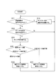
次に、音声出力回路1における動作の流れについて、図2のフローチャートを参照しながら説明する。
制御部17は、ユーザによる音量調整の指示がなされたか(ステップS11)、およびスイッチ切替の指示がなされたか(ステップS12)を、継続的に監視する。そして音量調整の指示がなされたときには(ステップS11のY)、制御部17は、アッテネータ11における音声信号の減衰率を、ユーザの指示に基づいて調整する(ステップS13)。これによりユーザは、既存スピーカ15若しくは外付けのスピーカから発せられる音声の音量を、所望の状態とすることが可能である。
また、スイッチ切替の指示がなされたときには(ステップS12のY)、制御部17は、スイッチ14を切替える(ステップS14)。これによりユーザは、所望の音声発生装置(既存スピーカ15、または、外部スピーカ端子16に接続された外付けのスピーカ)を通じて、音声を聞くことが出来る。
またステップS14の動作によって、スイッチ14が既存スピーカ15側に切替えられた場合には(ステップS15の「既存スピーカ側」)、制御部17は、電圧リミッタ回路12を有効に設定する(ステップS16)。一方、スイッチ14が外部スピーカ端子16側に切替えられた場合には(ステップS15の「外部スピーカ端子側」)、制御部17は、電圧リミッタ回路12を無効に設定する(ステップS17)。ステップS16またはステップS17の動作がなされた後、制御部17は、ステップS11の動作を繰り返す。
上述した動作により、増幅回路13からの音声信号の送出先が既存スピーカ15であるときは、電圧リミッタ回路12は有効とされ、当該送出先が外部スピーカ端子16であるときは、電圧リミッタ回路12は無効とされることになる。次に、先述したリミッタ制限値、およびアンプ制限値が、どのように設定されているかについて説明する。
まずリミッタ制限値(電圧リミッタ回路12に関する設定値)については、音声出力回路1の前段側からどのような大きさの音声信号が入力されても、電圧リミッタ回路12が有効とされた状態(かつ、アッテネータ11の減衰率がゼロの状態)で、増幅器13からの出力が、既存スピーカ15の定格入力を超えないようにする値に設定されている。
例えば既存スピーカ15の入力として5Wまでが許容される場合、増幅器13から送出される音声信号が必ず5W以下に収まるように、リミッタ制限値が設定されている。増幅器13の増幅率が設定された後であれば、このようにリミッタ制限値を設定することは可能である。
またアンプ制限値(増幅器13に関する設定値)については、電圧リミッタ回路12が無効とされた状態(かつ、アッテネータ11の減衰率がゼロの状態)で、音声出力回路1の前段側からどのような大きさの音声信号が入力されても、増幅器13からの出力が、外付けスピーカの定格入力を超えないようにする値に設定されている。
例えば外付けのスピーカの定格入力を10W/8オームとした場合、外部スピーカ端子16に8オームの負荷を接続した状態で、増幅器13から送出される音声信号が必ず10W以下に収まるように、アンプ制限値が設定されている。増幅器13の増幅率が設定された後であれば、このようなアンプ制限値の設定は可能である。
以上のようにリミッタ制限値およびアンプ制限値が設定されているため、上述した一連の動作(ステップS11~S17)がなされる音声出力回路1によれば、音声信号の送出先が既存スピーカ15と外部スピーカ端子16の何れとなっても、既存スピーカ15や外付けのスピーカに、定格入力を越える音声信号が入力されないようになっている。
つまり、増幅後の音声信号の送出先が外部スピーカ端子16であるときは、その信号の電力はアンプ制限値に応じて制限されることで、外付けスピーカの定格入力以下の範囲に収まる。また増幅後の音声信号の送出先が既存スピーカ15であるときは、その信号の電力はリミッタ制限値に応じて制限されることで、既存スピーカ15の定格入力(外付けスピーカの定格入力に比べて、低い値)以下の範囲に収まる。そのため、これらのスピーカが破壊されるという事態を未然に回避することが可能となっている。
なお以上の説明から、音声出力回路1では、増幅器13からの音声信号の送出先が既存スピーカ15に設定されているときは、外部スピーカ端子16に設定されているときに比べて、増幅器13から送出される音声信号の電力の上限値を低い値に制限する動作(制限動作)がなされるといえる。
また増幅器13の増幅率については、種々の値を設定することが可能であるが、一例として、EIAJ[Electronic Industries Association of Japan]規格に基づく場合の設定方法について説明する。
以下、外付けのスピーカが使用されるときに、EIAJ規格に基づいた音声信号の送出がなされるようにする場合について説明する。なおEIAJ規格によれば、音声信号の歪率(出力時の信号が、入力時の信号からどの程度歪んだかを示す)が10%に収まるようにすることが規定されている。そこで、標準的な電力レベルの音声信号(以下「基準信号」と称する)が音声出力回路1に入力されたときに、増幅後の基準信号の歪率が最大でも10%程度となるように、増幅器13の増幅率が設定されるようにする。
より具体的には、アッテネータ11での減衰率をゼロとし、電圧リミッタ回路12を無効とし、スイッチ14を外部スピーカ端子16側に接続し、外部スピーカ端子16に外付けスピーカ(或いはこれに相当する負荷)を接続させた状態で、音声出力回路1に基準信号を入力したときに、増幅後の基準信号(つまり外付けスピーカに送出される基準信号)の歪率が約10%となるように、増幅器13の増幅率を調整する。
なお増幅器13の増幅率の調整の過程では、外部スピーカ端子16に送出される音声信号は、例えば図3に示す通りとなる。なお図3の(a)は増幅率がα1の場合、(b)は増幅率がα2(>α1)の場合、(c)は増幅率がα3(>α2)の場合を、それぞれ表している。何れの場合も、基準信号の電圧に増幅率を乗じたものがアンプ制限値を超えている期間では、増幅後の基準信号の電圧はアンプ制限値にクリップ(固定)されている。そして、クリップの度合(修正の度合と見ることもできる)が大きいほど、増幅後の基準信号の波形は増幅前の波形から大きく歪むことになり、歪率は大きくなる。
増幅率がα1の場合は、増幅後の基準信号の歪率は、ほぼゼロ(10%より十分に小さい)となっている。よってこの場合の増幅率α1は、EIAJ規格を考慮すれば小さ過ぎる(歪の抑制の点では問題ないが、信号があまり増幅されない)といえる。
増幅率がα3の場合は、基準信号が増幅された結果、アンプ制限値へのクリップの度合が比較的大きくなっており、増幅後の基準信号の歪率は20%程度(10%に比べ非常に大きい)となっている。よってこの場合の増幅率α3は、EIAJ規格を考慮すれば大き過ぎる(音声出力回路1に基準信号が入力された場合でも、EIAJ規格を外れるおそれがある)といえる。
そして増幅率がα2の場合は、増幅された基準信号は、アンプ制限値へある程度クリップされているが、増幅後の基準信号の歪率は約10%となっている。そこで増幅率α2を、増幅器13の増幅率として採用する(設定する)こととする。このようにして、増幅器13の増幅率が設定された場合には、基準信号と同等の電力レベルまたはそれ以下の音声信号が音声出力回路1へ入力された場合に、音量調整が最大(アッテネータ11の減衰率がほぼゼロ)とされたときであっても、外付けスピーカに送出される音声信号の歪率は、EIAJ規格から外れたものとはならない。
またここで、既存スピーカ15が使用される状況について考える。音声出力回路1に入力された基準信号が、その電力レベルを維持したまま電圧リミッタ回路12に入ってしまうと、電圧リミッタ回路12の作用によって基準信号が大きく修正されてしまい、修正後の基準信号(増幅後、既存スピーカ15に送出される)がEIAJ規格(歪率が10%以内)に適合しなくなる虞がある。
この点、ユーザが音量を十分に小さくする指示を与えるようにすれば、これに応じてアッテネータ11での減衰率が大きくなり(ステップS11、S13の動作を参照)、修正後の基準信号の歪率はEIAJ規格に適合する程度となる。しかし音声出力回路1においては、ユーザがこのような指示を行わなくとも、自動的にアッテネータ11での減衰率が調整されるようにしても構わない。
例えば音声出力回路1の設計段階において、アッテネータ11の減衰率がどの値のときに、電圧リミッタ回路12(リミッタ制限値は既に設定されている)から出力される基準信号の歪率が約10%になるかを把握しておく(この値を「特定値」とする)。そして、増幅器13からの音声信号の送出先が既存スピーカ15に切替えられた場合には、アッテネータ11での減衰率が、この特定値を下回らないように、自動的に調整されるようにすれば良い。このようにすれば、修正後の基準信号の歪率はEIAJ規格に適合する程度となる。
またこの際、アッテネータ11での減衰率の最小値を当該特定値に固定しつつ、この最小値を下回らない範囲で、当該減衰率がユーザの指示に応じて変更可能となっていても良い。このようにすれば、歪率の大き過ぎる音声信号が既存スピーカ15に送出される事態を回避しつつ、既存スピーカ15の音量に、ユーザの音量調整の意図を極力反映させることが可能となる。
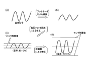
なお、アッテネータの減衰率が当該特定値に設定された場合には、基準信号の波形は、概ね図4に示すように変化することとなる。図4(a)で示すような波形の基準信号が音声出力回路1に入力されると、この基準信号は、まずアッテネータ11によって減衰され、図4(b)で示すような波形となる。このような波形となった基準信号は、更に電圧リミッタ回路12に入力され、リミッタ制限値を超えている期間はリミッタ制限値に修正される。これにより基準信号は、図4(c)で示すような波形となり、このときの基準信号の歪率は約10%である。
そして基準信号は更に増幅器13に入力されて増幅される。なお増幅後の基準信号は、アンプ制限値には達しない。そのため基準信号の波形は、図4(d)で示すように、歪率が変わらずに(約10%のまま)拡大されることとなる。基準信号はこのような波形に変化した後、既存スピーカ15に送出されることとなる。
[実施例2]
実施例1に係るスイッチ14は、制御部17の指示に応じて切替がなされていたが、スイッチの切替が、ユーザによって直接実行されるようにしても構わない。このようにした場合の音声出力回路1について、実施例2として以下に説明する。
実施例1に係るスイッチ14は、制御部17の指示に応じて切替がなされていたが、スイッチの切替が、ユーザによって直接実行されるようにしても構わない。このようにした場合の音声出力回路1について、実施例2として以下に説明する。
図5は、当該音声出力回路1の構成図である。図5に示すように本実施例では、スイッチ14の代わりに、スライドスイッチ(機構的スイッチの一種)14aが設けられている。スライドスイッチ14aは、スイッチ14と同様に、増幅器13の出力端子を、スピーカ15および外部スピーカ端子16の何れか一方に切替可能に接続するものである。しかしこの切替は、制御部17の指示によってではなく、ユーザがスライドスイッチ14aを直接操作することにより実現される。
そしてスライドスイッチ14aが既存スピーカ15側に切替えられたときは、これに連動して、制御部17にHレベル(Vcc)の信号が送られ、外部スピーカ端子16側に切替えられたときは、これに連動して、制御部17にLレベル(GND)の信号が送られる。制御部17は、スライドスイッチ14aが出力する信号に基づいて、スライドスイッチ14aがどのように切替えられたかを判別することができる。そして制御部17は、スライドスイッチ14aが既存スピーカ15側に切替えられたときは、電圧リミッタ回路12を有効に設定し、外部スピーカ端子16側に切替えられたときは、電圧リミッタ回路12を無効に設定する。
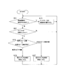
本実施例における動作の流れを、図6のフローチャートに示す。基本的には実施例1に係る動作の流れと同様であるが、本実施例では、制御部17は、ユーザによるスイッチ14の切替の指示がなされたか(ステップS12)を監視する代わりに、スライドスイッチ14aが切替えられたか(ステップS21)を監視する。またスライドスイッチ14aはユーザによって切替えられるため、制御部17は、スイッチを切替える動作(ステップS14)を行わない。
なお、上述したスライドスイッチ14aが出力する信号については、直接、電圧リミッタ回路12に送られるようにしても良い。そしてこの場合、電圧リミッタ回路12は、スライドスイッチ14aから送られてきた信号に応じて、有効または無効に設定されるようにしても良い。このようにすれば、電圧リミッタ回路12における有効と無効の切替が、制御部17の処理負担を増やすことなく実現される。
[実施例3]
実施例1では、増幅後の音声信号の送出先が何れに設定されているかに応じて、電圧リミッタ回路12の有効/無効が切替えられるようになっていたが、その代わりに、リミッタ制限値が切替えられるようにしても構わない。なお本実施例では、電圧リミッタ回路12は常に有効であり、無効とはならない。このようにした場合の音声出力回路1について、実施例3として以下に説明する。
実施例1では、増幅後の音声信号の送出先が何れに設定されているかに応じて、電圧リミッタ回路12の有効/無効が切替えられるようになっていたが、その代わりに、リミッタ制限値が切替えられるようにしても構わない。なお本実施例では、電圧リミッタ回路12は常に有効であり、無効とはならない。このようにした場合の音声出力回路1について、実施例3として以下に説明する。
本実施例に係る音声出力回路1の全体的な構成としては、基本的に実施例1のもの(図1を参照)と同様である。しかし本実施例に係る電圧リミッタ回路12は、制御部17の指示に応じて、リミッタ制限値を第1リミッタ制限値と第2リミッタ制限値の何れかに、切替可能に設定することが可能となっている。
ここで第1制限値は、概ね、実施例1の増幅器13に設定されているアンプ制限値を当該増幅器13の増幅率で除した値に、予め設定されている。つまり第1制限値は、実施例1におけるアンプ制限値と同様の趣旨で設定されている。また第2制限値は、実施例1の電圧リミッタ回路12に設定されているリミッタ制限値と同等の値に、予め設定されている。その結果、第2制限値は、第1制限値より低い値に設定されている。
そして制御部17は、スイッチ14が既存スピーカ15側に切替えられたときは、リミッタ制限値を第2リミッタ制限値に設定し、外部スピーカ端子16側に切替えられたときは、リミッタ制限値を第1リミッタ制限値に設定する。
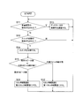
本実施例における動作の流れを、図7のフローチャートに示す。基本的には実施例1に係る動作の流れと同様であるが、本実施例では、電圧リミッタ回路を有効に設定する(ステップS16)代わりに、リミッタ制限値を第2リミッタ制限値に設定し(ステップS31)、また、電圧リミッタ回路を無効に設定する(ステップS17)代わりに、リミッタ制限値を第1リミッタ制限値に設定する(ステップS32)ようになっている。
本実施例によれば、電圧リミッタ回路12の作用によって、既存スピーカ15に定格入力以上の音声信号が送出されることを防ぐだけでなく、外付けスピーカに定格入力以上の音声信号が送出されることを防ぐことも可能である。
以上に説明した通り、各実施例に係る音声出力回路1は、前段側から入力された音声信号を、増幅させて後段側に送出する増幅器13と、増幅器13から送出された音声信号を受け、該音声信号に基づいて音声を生成する既存スピーカ15と、増幅器13から送出された音声信号を受け、該音声信号を、自身に接続された外付けのスピーカに送る外部スピーカ端子16と、増幅器13からの音声信号の送出先を、既存スピーカ15と外部スピーカ端子16の何れかに、切替可能に設定するスイッチ14と、を備えている。
更に音声出力回路1は、増幅器13からの音声信号の送出先が、何れに設定されているかを判別する機能(判別機能)や、増幅器13からの音声信号の送出先が既存スピーカ15に設定されているときは、外部スピーカ端子16に設定されているときに比べて、増幅器13から送出される音声信号の電力の上限値を低い値に制限する機能(制限機能)を有する機能部(主に、電圧リミッタ12と制御部17が該当する)を備えている。そのため、音声信号の送出先が既存スピーカ15となった場合であっても、既存スピーカ15に過大な音声信号が送出されないようにすることが可能となっている。
なお先述した通り、音声出力回路1は、画像表示装置(例えばテレビ放送受像機のように、画像信号の入力を受付けて、この画像信号に基づいた画像を表示する機器)に備えられる。特に、省スペース化が望まれる薄型の画像表示装置に備えられることにより、音声出力回路1は、この薄型化を出来るだけ阻害せずに、音声を増幅させて出力することができる。
但し音声出力回路1は、画像表示装置に限らず、音声信号を扱う種々の電気機器に備えることが可能である。音声出力回路1が備えられた電気機器は、音声信号の入力を受付け、この音声信号を音声出力回路1に入力させることにより、この音声信号に基づいた音声を既存スピーカ15または外付けのスピーカに生成させることができる。
以上、本発明の実施形態について説明したが、本発明はこの内容に限定されるものではない。また本発明の実施形態は、本発明の主旨を逸脱しない限り、種々の改変を加えることが可能である。
Claims (5)
- 前段側から入力された音声信号を、増幅させて後段側に送出する増幅器と、
前記増幅器から送出された音声信号を受け、該音声信号に基づいて音声を生成する既存スピーカと、
前記増幅器から送出された音声信号を受け、該音声信号を、自身に接続された外付けのスピーカに送る外部スピーカ端子と、
前記増幅器からの音声信号の送出先を、前記既存スピーカと前記外部スピーカ端子の何れかに、切替可能に設定するスイッチと、
前記増幅器からの音声信号の送出先が、何れに設定されているかを判別する判別部と、
前記増幅器からの音声信号の送出先が前記既存スピーカに設定されているときは、前記外部スピーカ端子に設定されているときに比べて、前記増幅器から送出される音声信号の電力の上限値を低い値に制限する制限動作を行う、上限制限手段を備えたことを特徴とする音声出力回路。 - 前記上限制限手段は、
前段側から伝送されてきた音声信号について、電力が所定の制限値を超えている期間には、当該電力を該制限値にクリップさせた上で後段側に送出する、リミッタ回路を有し、
前記増幅器からの音声信号の送出先が前記外部スピーカ端子に設定されているときは、前記リミッタ回路を無効とし、
前記増幅器からの音声信号の送出先が前記既存スピーカに設定されているときは、前記リミッタ回路を有効とすることで、前記制限動作を行うことを特徴とする請求項1に記載の音声出力回路。 - 前記上限制限手段は、
予め制限値が変更可能に設定され、前段側から伝送されてきた音声信号について、電力が該制限値を超えている期間には、当該電力を該制限値にクリップさせた上で後段側に送出する、制限値可変リミッタ回路を有し、
前記増幅器からの音声信号の送出先が前記外部スピーカ端子に設定されているときは、前記制限値を第1制限値に設定し、
前記増幅器からの音声信号の送出先が前記既存スピーカに設定されているときは、前記制限値を、第1制限値より低い第2制限値に設定することで、前記制限動作を行うことを特徴とする請求項1に記載の音声出力回路。 - 請求項1に記載の音声出力回路を備えた電気機器であって、
音声信号の入力を受付け、該音声信号を前記音声出力回路に入力させることにより、該音声信号に基づいた音声を前記既存スピーカまたは外付けのスピーカに生成させることを特徴とする電気機器。 - 画像信号の入力をも受付け、該画像信号に基づいた画像を表示する画像表示装置であることを特徴とする請求項4に記載の電気機器。
Applications Claiming Priority (2)
| Application Number | Priority Date | Filing Date | Title |
|---|---|---|---|
| JP2009-273772 | 2009-12-01 | ||
| JP2009273772A JP2011119863A (ja) | 2009-12-01 | 2009-12-01 | 音声出力回路および電気機器 |
Publications (1)
| Publication Number | Publication Date |
|---|---|
| WO2011068012A1 true WO2011068012A1 (ja) | 2011-06-09 |
Family
ID=44114869
Family Applications (1)
| Application Number | Title | Priority Date | Filing Date |
|---|---|---|---|
| PCT/JP2010/069894 Ceased WO2011068012A1 (ja) | 2009-12-01 | 2010-11-09 | 音声出力回路および電気機器 |
Country Status (2)
| Country | Link |
|---|---|
| JP (1) | JP2011119863A (ja) |
| WO (1) | WO2011068012A1 (ja) |
Citations (3)
| Publication number | Priority date | Publication date | Assignee | Title |
|---|---|---|---|---|
| JPH0879877A (ja) * | 1994-08-31 | 1996-03-22 | Sanyo Electric Co Ltd | 音声処理出力装置 |
| JP2000287294A (ja) * | 1999-03-31 | 2000-10-13 | Matsushita Electric Ind Co Ltd | 音響装置 |
| JP2009253926A (ja) * | 2008-04-11 | 2009-10-29 | Mitsubishi Electric Corp | 音声出力アンプ装置 |
-
2009
- 2009-12-01 JP JP2009273772A patent/JP2011119863A/ja active Pending
-
2010
- 2010-11-09 WO PCT/JP2010/069894 patent/WO2011068012A1/ja not_active Ceased
Patent Citations (3)
| Publication number | Priority date | Publication date | Assignee | Title |
|---|---|---|---|---|
| JPH0879877A (ja) * | 1994-08-31 | 1996-03-22 | Sanyo Electric Co Ltd | 音声処理出力装置 |
| JP2000287294A (ja) * | 1999-03-31 | 2000-10-13 | Matsushita Electric Ind Co Ltd | 音響装置 |
| JP2009253926A (ja) * | 2008-04-11 | 2009-10-29 | Mitsubishi Electric Corp | 音声出力アンプ装置 |
Also Published As
| Publication number | Publication date |
|---|---|
| JP2011119863A (ja) | 2011-06-16 |
Similar Documents
| Publication | Publication Date | Title |
|---|---|---|
| US8615094B2 (en) | Automatic level control circuit | |
| JP5525508B2 (ja) | 周囲ノイズ検出を使用する明瞭度コントロール | |
| US7042986B1 (en) | DSP-enabled amplified telephone with digital audio processing | |
| CN104503297B (zh) | Dsp音频数字信号处理系统与方法 | |
| CN104935742B (zh) | 移动通讯终端及改善其在听筒模式下的音质的方法 | |
| CN1725905A (zh) | 助听器系统和在接收音频时运行助听器系统的方法 | |
| CN111954122A (zh) | 扬声器系统及包含扬声器系统的通信装置和免提电话 | |
| RU2424632C2 (ru) | Устройство радиосвязи с двусторонним аудиосигналом | |
| CN102857228A (zh) | 电子设备及其音频输出控制方法 | |
| JP2009253926A (ja) | 音声出力アンプ装置 | |
| CN106060711A (zh) | 音频播放装置、终端设备及方法 | |
| CN106851488A (zh) | 音频输出的控制方法、装置和电路 | |
| JP5928102B2 (ja) | 音調整装置、音調整方法、及び音調整プログラム | |
| JP2014096732A (ja) | 収音装置及び電話機 | |
| WO2011148624A1 (ja) | 音量振幅制限装置 | |
| CN1169077A (zh) | 向电话用户提供控制该用户话音临界音量的设备和方法 | |
| JP2004312141A (ja) | 信号レベル調整装置、音声出力装置 | |
| KR101519435B1 (ko) | 엑티브스피커용 대기전력 차단 장치 | |
| JP2011119863A (ja) | 音声出力回路および電気機器 | |
| JP2006157611A (ja) | 端末装置及びこの端末装置の制御方法 | |
| CN105246017B (zh) | 一种音频数字信号处理器及系统 | |
| CN115550820A (zh) | 扬声器控制方法、装置、电子设备及存储介质 | |
| CN101252743A (zh) | 一种多模通信终端、音频系统及其控制方法 | |
| US20260046560A1 (en) | Audio signal processing method and audio signal processing device | |
| JP5513907B2 (ja) | 自動レベル制御回路およびそれを用いたオーディオ用デジタル信号プロセッサ、電子機器ならびに可変利得増幅器の利得制御方法 |
Legal Events
| Date | Code | Title | Description |
|---|---|---|---|
| 121 | Ep: the epo has been informed by wipo that ep was designated in this application |
Ref document number: 10834464 Country of ref document: EP Kind code of ref document: A1 |
|
| NENP | Non-entry into the national phase |
Ref country code: DE |
|
| 122 | Ep: pct application non-entry in european phase |
Ref document number: 10834464 Country of ref document: EP Kind code of ref document: A1 |