WO2011065729A2 - Biosensor - Google Patents
Biosensor Download PDFInfo
- Publication number
- WO2011065729A2 WO2011065729A2 PCT/KR2010/008305 KR2010008305W WO2011065729A2 WO 2011065729 A2 WO2011065729 A2 WO 2011065729A2 KR 2010008305 W KR2010008305 W KR 2010008305W WO 2011065729 A2 WO2011065729 A2 WO 2011065729A2
- Authority
- WO
- WIPO (PCT)
- Prior art keywords
- channel
- blood
- biosensor
- introduction
- main body
- Prior art date
Links
- HLIVGQVJCQRXFI-UHFFFAOYSA-N CC(C1C2)C3C1=C2CC3 Chemical compound CC(C1C2)C3C1=C2CC3 HLIVGQVJCQRXFI-UHFFFAOYSA-N 0.000 description 1
Images


Classifications
-
- B—PERFORMING OPERATIONS; TRANSPORTING
- B01—PHYSICAL OR CHEMICAL PROCESSES OR APPARATUS IN GENERAL
- B01L—CHEMICAL OR PHYSICAL LABORATORY APPARATUS FOR GENERAL USE
- B01L3/00—Containers or dishes for laboratory use, e.g. laboratory glassware; Droppers
- B01L3/50—Containers for the purpose of retaining a material to be analysed, e.g. test tubes
- B01L3/502—Containers for the purpose of retaining a material to be analysed, e.g. test tubes with fluid transport, e.g. in multi-compartment structures
- B01L3/5027—Containers for the purpose of retaining a material to be analysed, e.g. test tubes with fluid transport, e.g. in multi-compartment structures by integrated microfluidic structures, i.e. dimensions of channels and chambers are such that surface tension forces are important, e.g. lab-on-a-chip
- B01L3/502746—Containers for the purpose of retaining a material to be analysed, e.g. test tubes with fluid transport, e.g. in multi-compartment structures by integrated microfluidic structures, i.e. dimensions of channels and chambers are such that surface tension forces are important, e.g. lab-on-a-chip characterised by the means for controlling flow resistance, e.g. flow controllers, baffles
-
- G—PHYSICS
- G01—MEASURING; TESTING
- G01N—INVESTIGATING OR ANALYSING MATERIALS BY DETERMINING THEIR CHEMICAL OR PHYSICAL PROPERTIES
- G01N33/00—Investigating or analysing materials by specific methods not covered by groups G01N1/00 - G01N31/00
- G01N33/48—Biological material, e.g. blood, urine; Haemocytometers
- G01N33/483—Physical analysis of biological material
- G01N33/487—Physical analysis of biological material of liquid biological material
- G01N33/49—Blood
-
- C—CHEMISTRY; METALLURGY
- C12—BIOCHEMISTRY; BEER; SPIRITS; WINE; VINEGAR; MICROBIOLOGY; ENZYMOLOGY; MUTATION OR GENETIC ENGINEERING
- C12Q—MEASURING OR TESTING PROCESSES INVOLVING ENZYMES, NUCLEIC ACIDS OR MICROORGANISMS; COMPOSITIONS OR TEST PAPERS THEREFOR; PROCESSES OF PREPARING SUCH COMPOSITIONS; CONDITION-RESPONSIVE CONTROL IN MICROBIOLOGICAL OR ENZYMOLOGICAL PROCESSES
- C12Q1/00—Measuring or testing processes involving enzymes, nucleic acids or microorganisms; Compositions therefor; Processes of preparing such compositions
- C12Q1/02—Measuring or testing processes involving enzymes, nucleic acids or microorganisms; Compositions therefor; Processes of preparing such compositions involving viable microorganisms
- C12Q1/24—Methods of sampling, or inoculating or spreading a sample; Methods of physically isolating an intact microorganisms
-
- G—PHYSICS
- G01—MEASURING; TESTING
- G01N—INVESTIGATING OR ANALYSING MATERIALS BY DETERMINING THEIR CHEMICAL OR PHYSICAL PROPERTIES
- G01N33/00—Investigating or analysing materials by specific methods not covered by groups G01N1/00 - G01N31/00
- G01N33/48—Biological material, e.g. blood, urine; Haemocytometers
- G01N33/50—Chemical analysis of biological material, e.g. blood, urine; Testing involving biospecific ligand binding methods; Immunological testing
- G01N33/5005—Chemical analysis of biological material, e.g. blood, urine; Testing involving biospecific ligand binding methods; Immunological testing involving human or animal cells
- G01N33/5094—Chemical analysis of biological material, e.g. blood, urine; Testing involving biospecific ligand binding methods; Immunological testing involving human or animal cells for blood cell populations
-
- B—PERFORMING OPERATIONS; TRANSPORTING
- B01—PHYSICAL OR CHEMICAL PROCESSES OR APPARATUS IN GENERAL
- B01L—CHEMICAL OR PHYSICAL LABORATORY APPARATUS FOR GENERAL USE
- B01L2300/00—Additional constructional details
- B01L2300/06—Auxiliary integrated devices, integrated components
- B01L2300/0627—Sensor or part of a sensor is integrated
- B01L2300/0645—Electrodes
-
- B—PERFORMING OPERATIONS; TRANSPORTING
- B01—PHYSICAL OR CHEMICAL PROCESSES OR APPARATUS IN GENERAL
- B01L—CHEMICAL OR PHYSICAL LABORATORY APPARATUS FOR GENERAL USE
- B01L2300/00—Additional constructional details
- B01L2300/08—Geometry, shape and general structure
- B01L2300/0809—Geometry, shape and general structure rectangular shaped
- B01L2300/0825—Test strips
-
- B—PERFORMING OPERATIONS; TRANSPORTING
- B01—PHYSICAL OR CHEMICAL PROCESSES OR APPARATUS IN GENERAL
- B01L—CHEMICAL OR PHYSICAL LABORATORY APPARATUS FOR GENERAL USE
- B01L2300/00—Additional constructional details
- B01L2300/08—Geometry, shape and general structure
- B01L2300/0887—Laminated structure
-
- B—PERFORMING OPERATIONS; TRANSPORTING
- B01—PHYSICAL OR CHEMICAL PROCESSES OR APPARATUS IN GENERAL
- B01L—CHEMICAL OR PHYSICAL LABORATORY APPARATUS FOR GENERAL USE
- B01L2400/00—Moving or stopping fluids
- B01L2400/04—Moving fluids with specific forces or mechanical means
- B01L2400/0403—Moving fluids with specific forces or mechanical means specific forces
- B01L2400/0406—Moving fluids with specific forces or mechanical means specific forces capillary forces
-
- B—PERFORMING OPERATIONS; TRANSPORTING
- B01—PHYSICAL OR CHEMICAL PROCESSES OR APPARATUS IN GENERAL
- B01L—CHEMICAL OR PHYSICAL LABORATORY APPARATUS FOR GENERAL USE
- B01L3/00—Containers or dishes for laboratory use, e.g. laboratory glassware; Droppers
- B01L3/50—Containers for the purpose of retaining a material to be analysed, e.g. test tubes
- B01L3/502—Containers for the purpose of retaining a material to be analysed, e.g. test tubes with fluid transport, e.g. in multi-compartment structures
- B01L3/5027—Containers for the purpose of retaining a material to be analysed, e.g. test tubes with fluid transport, e.g. in multi-compartment structures by integrated microfluidic structures, i.e. dimensions of channels and chambers are such that surface tension forces are important, e.g. lab-on-a-chip
- B01L3/502707—Containers for the purpose of retaining a material to be analysed, e.g. test tubes with fluid transport, e.g. in multi-compartment structures by integrated microfluidic structures, i.e. dimensions of channels and chambers are such that surface tension forces are important, e.g. lab-on-a-chip characterised by the manufacture of the container or its components
Definitions
- the present invention relates to a biosensor, and more particularly, to a biosensor having increased manufacturing reproducibility by limiting a size of a microchannel separating blood cells in the width direction.
- POCT point of care testing
- biochip companies are conducting research.
- the need for rapid testing is increasing at the time of the occurrence of various new virus diseases, and thus the market demand for a mechanism for simple separation of blood cells and blood from whole blood in a short time. It is also increasing.
- the simplest way to separate blood cells and hepatocytes from whole blood is to install a filler in the channel through which whole blood flows to separate red blood cells and white blood cells by controlling the hydrodynamic resistance and fluid flow of whole blood in the channel. .
- the method only shows the possibility that blood cells present in whole blood can be separated when the filler is installed in the channel, and the complete separation is not shown due to the limitation of the filler configuration.
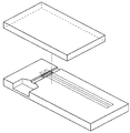
- the method may include Korean Patent No. 841856 as shown in FIG. 1.
- the patent is a structure that separates blood cells and plasma from whole blood through a gap from the submicro to nanometer (the vertical height of the channel), and is characterized in that the plasma and blood cells are separated by force without using the capillary phenomenon of the gap. .
- the senor illustrated in FIG. 1 has a jaw in a channel through which whole blood flows, and thus it is not easy to manufacture the sensor accurately in a structure in which microscale and macroscale are mixed.
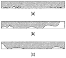
- FIG. 2 is a schematic representation of the actual multi-sided formation of a device fabricated with a target gap of 0.6 ⁇ m on the top plate of a glass wafer and the bottom plate of a silicon wafer.
- the shape of the cross section, particularly the lower surface is very irregular, and in the dicing process in which the cross-sectional state of the channel is the last process, debris of silicon and glass flows into the channel and thus may not be properly cleaned, thereby acting as a resistance in the channel.
- the fragments act as a binding material between the upper plate and the lower plate forming the channel, the channel is not formed properly.
- the present invention provides a biosensor comprising a main body and an upper substrate bonded to an upper end of the main body, wherein the blood is formed on the upper surface of the main body; A channel formed on an upper surface of the main body and communicating with one side of the introduction means; And a discharging means formed on the upper surface of the main body and communicating with the other side of the channel and discharging air into the channel for the blood movement to the outside, wherein the channel has a minimum width in some sections.
- the width is 0.5 ⁇ m or more and 1 ⁇ m or less, and the height of the channel is 10 times the minimum width.
- the channel is characterized in that a single width.
- the introduction means is a first side of the channel, and the discharge means is a second side of the channel.
- the introduction means is a blood introduction portion formed on the upper surface of the body, the discharge means is a second side surface of the channel, the upper substrate is characterized in that the introduction hole is formed in a position corresponding to the blood introduction portion.
- the introduction means is a blood introduction portion formed on the upper surface of the body
- the discharge means is a blood storage portion formed on the upper surface of the body
- the upper substrate has an introduction hole and the blood storage portion at a position corresponding to the blood introduction portion.
- the discharge hole is formed in a position corresponding to the.
- the channel may include a first channel portion having a nozzle shape and a second channel portion having a single width.
- the present invention through the above-described problem solving means is limited to the width of the microchannel to the size for capillary action and blood cell separation, and further limited to the height 10 times the width of the channel, the production of the entire biosensor only by sub-micro level process Since it is possible to produce high reproducibility, and also to form the channel in the form of a nozzle rather than a single width, there is an effect to improve the efficiency of blood separation.
- FIG. 1 is a perspective view illustrating a conventional biosensor.
- FIG. 2A, 2B, and 3C are schematic views illustrating the cross-sectional shape of the biosensor of FIG. 1 after fabrication.
- FIG. 3 is an exploded perspective view showing an embodiment of a biosensor according to the present invention.
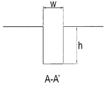
- FIG. 4 is a cross-sectional view of A-A of the biosensor of FIG. 3.
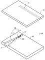
- FIG. 5 is an exploded perspective view showing another embodiment of the biosensor according to the present invention.
- FIG. 6 is an exploded perspective view showing another embodiment of the biosensor according to the present invention.
- FIG. 7 is an exploded perspective view showing another embodiment of the biosensor according to the present invention.
- FIG. 8 is an exploded perspective view showing another embodiment of the biosensor according to the present invention.
- FIG. 9 is an exploded perspective view showing another embodiment of the biosensor according to the present invention.
- FIG. 3 shows a first embodiment of the present invention.
- the biosensor 100 includes a sensor main body 10 and an upper substrate 20, and a channel 30 through which the injected blood is separated is formed in the main body, and the upper substrate 20 is the upper substrate 20. It is coupled to the upper surface of the body (10).
- the channel 30 is formed as a groove from the first side 31 of the main body 10 to the opposite second side 32.
- the channel 30 has three surfaces formed by the main body 10 and the upper surface of the upper substrate 20 forms the remaining surfaces. .
- the blood is introduced from the first side 31 of the channel 30 as the inflow means, and the second side 32 as the discharge means for smooth movement of the blood serves as a through hole of the channel 30.
- FIG. 1 A-A cross section of the channel 30 is shown in FIG.
- one of the width and height of the channel 30 should be 1 ⁇ m or less, so the width of the channel 30 is limited to 0.5 ⁇ m or more and 1 ⁇ m or less for the manufacturing process. It was.
- the width is 1 ⁇ m or more, blood cells cannot be separated from the blood, and when 0.5 ⁇ m or less, it is difficult to produce the sub micro level, resulting in a rapid drop in productivity.
- And h is preferably limited to 10 ⁇ w for fine groove processing by fine processing.
- the aspect ratio (h / w ratio) is 10 or more, since it is difficult to process in a general lithography process, and develop a separate process applied to the rapid drop in mass productivity.
- the width of the grooves is formed in an accurate shape, but the height of the grooves is difficult to form as designed by the processing by-products.
- the height of the channel 30 is limited to 1 ⁇ m or less and manufactured by fine processing, there is a disadvantage in that the height is not properly formed by processing by-products, but the biosensor 100 of the present invention has a width of 0.5 ⁇ m or more.
- the grooves formed by limiting the cross section of the grooves by any processing by-products are limited to 1 ⁇ m or less and 5 ⁇ m or more and 10 ⁇ m or less in height, which serves as a basic channel 30.
- the channel 30 may be formed in a curved shape as needed, and the width of the channel may vary in the length direction, but at least some sections of the channel may have a width of 0.5 ⁇ m or more and 1 ⁇ m or less to separate blood cells. .
- the channel 30 may be formed of a plurality of independent grooves, respectively, as necessary.
- the channel 30 may have a plurality of grooves formed on the first side surface 31 as needed, and each of the grooves may be joined to the center portion so that one groove passes through the second side surface at the end thereof. .
- the plasma separated by the biosensor 100 may be measured by an electrochemical or spectroscopic method through a biochemical reaction or a chemical reaction including an enzymatic reaction or an immunological reaction.
- the materials of the body 10 and the upper substrate 20 are made transparent.
- the material is transparent polymer or transparent glass.
- the biosensor 100 has an enzyme 60 seated on the channel 30 for electrochemical measurement, and an electromotive force formed by the reaction of the enzyme 60 and plasma on the lower surface of the upper substrate 20.
- An electrode 70 for measuring can be formed.
- the electrode 70 serves to provide an electromotive force generated by being connected to a measuring device (not shown) to the measuring device.
- the channel 30 of the biosensor of the present invention may be configured in two different forms.
- the first channel portion 33 is in the form of a nozzle in the direction of blood movement, and the second channel portion 34 is generally in the form of a groove having a constant width.
- the first channel part 33 has a width that narrows in the fluid moving direction, thereby increasing the fluid flow rate.
- the plasma of the channel 30 is separated by the second channel portion 34.
- the inflow means of the biosensor may have a wider first side 31 than in the embodiment of FIG. 3 to increase the inflow amount of blood.
- the width of the second channel part 34 is 0.5 ⁇ m or more and 1 ⁇ m or less, and the height of the entire channel 30 is 5 ⁇ m or more and 10 ⁇ m or less.
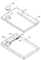
- FIGS 6 and 7 show an embodiment in which the inlet means for the inflow of blood is configured on the upper surface of the biosensor 100.
- the blood of the biosensor 100 is placed in the blood introduction portion 40, the plasma is separated into the channel 30 by the capillary action of the channel 30, the discharge means is the second side (32).
- An introduction hole 21 having the same size as the blood introduction portion 40 is formed in the upper substrate 20 of the biosensor 100, and the introduction hole 21 has a rubber stopper 80 for promoting blood movement. Is fitted.
- the rubber stopper 80 closes the introduction hole 21 and presses the rubber stopper 80 to accelerate the movement of the blood by the pressing force, thereby providing rapid blood separation.
- the enzyme 60 and the electrode 70 may be formed on the lower surface of the channel 30 and the upper substrate 20, respectively, to perform electrochemical measurements.
- the entire biosensor 100 may be formed of a transparent material for optical measurement.
- the enzyme 60 and the electrode 70 may be omitted.
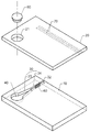
- the channel 30 may be configured to have a single groove as shown in FIG. 6, and may be configured as shown in FIG. 7 if necessary.
- the channel 10 shown in FIG. 7 has a first channel portion 33 in contact with the blood introduction portion 40 in the form of a nozzle, and the second channel portion 34 in communication with the second end surface has a single width.
- the flow of blood is accelerated by the nozzle effect on the first channel portion 33 and the actual plasma separation is performed in the second channel portion 34.
- the channel 30 has a width of the second channel portion 34 having a minimum width of 0.5 ⁇ m or more and 1 ⁇ m or less and a height of 5 ⁇ m or more and 10 ⁇ m or less, which is 10 times the width.
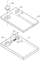
- a separate blood storage unit 50 may be formed in the main body.
- the discharge hole 22 is formed at the same size and the same position as the blood storage unit 50 in the upper substrate 20.
- the enzyme may be located in the blood storage unit 50, and the electrode may be formed on the upper surface of the main body 10, and the channel 30 may be formed on the lower surface of the upper substrate 20. ) To position the enzyme 60 and avoid the discharge hole 22 to form the electrode 70 on the lower surface of the upper substrate 20.
- the channel 30 may have a constant width, and as shown in FIG. 9, the first channel portion 33 having a nozzle shape and the second channel portion having a single width ( 34) can be configured.
- a plurality of channels 30 may be configured to connect the blood introduction part 40 and the blood storage part 50.
- the blood introduction part 40 and the blood storage part 50 are formed on the upper surface of the main body 10 at the same height as the height of the channel 30.
- the manufacturing of the main body 10 is possible only by the process of micro-scale during manufacture, and thus has high manufacturing efficiency.
- all the channels 30 of the above embodiments may be treated with various hydrophilic materials on the surface to control the inflow rate of blood and plasma, or may be mechanically treated with a plasma treatment or a micropattern.
Abstract
The present invention relates to a biosensor, and more specifically relates to a biosensor in which the production reproducibility is enhanced by limiting the size, in the width direction, of a micro-channel for separating blood cells. In order to achieve the above aim, the present invention provides a biosensor which incorporates a main body and an upper plate joined to the upper edge of the main body, and which comprises: an introducing means for introducing blood formed on the upper surface of the main body; a channel which is formed on the upper surface of the main body and of which one side connects through to the introducing means; and a discharge means which is formed on the upper surface of the main body, connects through to the other side of the channel, and discharges air inside the channel to the outside for the purpose of blood movement; wherein the channel has a minimum width in one section, the minimum width is no less than 0.5 μm and no more than 1 μm, and the height of the channel is 10 times the minimum width.
Description
본 발명은 바이오 센서에 관한 것으로, 더욱 상세하게는 혈구를 분리하는 미세 채널을 폭 방향으로 크기를 한정하여 제작 재현성을 높인 바이오 센서에 관한 것이다.The present invention relates to a biosensor, and more particularly, to a biosensor having increased manufacturing reproducibility by limiting a size of a microchannel separating blood cells in the width direction.
전혈(whole blood) 상에서 혈구(blood cell)와 혈장(plasma)을 분리하는 기술은 POCT(point of care testing)에서 매우 중요한 핵심 기술로 많이 바이오 칩 회사들이 관련 연구를 수행하고 있다. 특히 여러 가지 신규 바이러스에 의한 질환들이 발생하고 있는 시점에서 빠른 검사(rapid testing)에 대한 필요성이 증가되고 있으며, 이에 따라 전혈상에서 혈구와 혈액을 빠른 시간 내에 간단히 분리할 수 있는 메카니즘에 대한 시장의 요구도 점점 증가하고 있는 실정이다.The technology of separating blood cells and plasma on whole blood is a key technology in point of care testing (POCT), and many biochip companies are conducting research. In particular, the need for rapid testing is increasing at the time of the occurrence of various new virus diseases, and thus the market demand for a mechanism for simple separation of blood cells and blood from whole blood in a short time. It is also increasing.
가장 간단히 전혈상에서 혈구와 핼액을 분리할 수 있는 방법은 전혈이 흐르는 채널 내에 필러를 설치하여 채널 내의 전혈의 유체역학적인 저항과 유체 흐름을 제어하여 적혈구 및 백혈구를 분리할 수 있는 방법을 들 수 있다.The simplest way to separate blood cells and hepatocytes from whole blood is to install a filler in the channel through which whole blood flows to separate red blood cells and white blood cells by controlling the hydrodynamic resistance and fluid flow of whole blood in the channel. .
상기 방법은 채널 내에 필러를 설치할 경우 전혈내에 존재하는 혈구들이 분리될 수 있는 가능성만을 보여주는 것으로 필러 구성의 한계에 의하여 완전한 분리는 보여주지 못하는 단점이 있다.The method only shows the possibility that blood cells present in whole blood can be separated when the filler is installed in the channel, and the complete separation is not shown due to the limitation of the filler configuration.
상기 방법을 좀 더 구체화한 것으로 도 1에 도시된 바와 같은 대한민국 특허 제841856호를 들 수 있다. 상기 특허는 서브 마이크로부터 나노미터까지의 갭(채널의 수직 높이)을 통하여 전혈상의 혈구와 혈장을 분리하는 구조로 갭의 모세관 현상을 이용하여 무동력으로 혈장과 혈구를 분리하는 것에 특징이 있는 구성이다.More specifically, the method may include Korean Patent No. 841856 as shown in FIG. 1. The patent is a structure that separates blood cells and plasma from whole blood through a gap from the submicro to nanometer (the vertical height of the channel), and is characterized in that the plasma and blood cells are separated by force without using the capillary phenomenon of the gap. .
그러나 상기 발명을 실제 제품으로 생산하거나 Q/C공정을 수행할 경우에 1μm이하의 갭을 제조 공정으로 제어하기에는 큰 어려움이 있다. 특히 반도체 공정, 마이크로머시닝, 사출성형 등과 같은 정밀 가공 방식으로 제조를 하더라도 각 센서마다 편차가 발생하며, 그 편차의 영향으로 일정한 신뢰성을 갖는 센서를 대량 생산하기는 어려워 재현성의 문제가 발생한다.However, when the invention is produced as a real product or a Q / C process is performed, it is difficult to control a gap of 1 μm or less into a manufacturing process. In particular, even if manufactured by a precision processing method such as semiconductor processing, micromachining, injection molding, etc. deviation occurs for each sensor, it is difficult to mass-produce a sensor having a certain reliability under the influence of the deviation, the problem of reproducibility occurs.
특히, 도 1에 도시된 센서는 전혈이 흐르는 채널에 턱이 존재하여, 마이크로 스케일과 매크로 스케일이 혼재한 형태로 설정한 구조로 정확한 제조하기가 쉽지 않다.In particular, the sensor illustrated in FIG. 1 has a jaw in a channel through which whole blood flows, and thus it is not easy to manufacture the sensor accurately in a structure in which microscale and macroscale are mixed.
또한, 1μm이하의 갭을 가지는 채널을 형성한다 하더라도 기판의 재질에 따라 처짐에 의해 채널이 붙어 버리는 현상도 나타나기 때문에 유체(전혈)가 흐를 수 있는 채널의 역할을 충실히 수행하기 어렵고, 채널 내에 상기 특허와 같이 2전극 또는 3전극 시스템으로 전극을 패터닝할 때 채널과 표면의 단차부분에서 전극이 끊어지는 현상이 발생하기 때문에 더더욱 제조가 어려운 단점이 있다.In addition, even if a channel having a gap of 1 μm or less is formed, it is difficult to faithfully play the role of a channel through which fluids (whole blood) can flow due to deflection depending on the material of the substrate. As described above, when the electrode is patterned by the two-electrode or three-electrode system, the electrode is disconnected at the stepped portion of the channel and the surface.
더욱이 폴리머 재질을 이용하여 디바이스를 제작할 경우, 구현하고자 하는 채널의 갭을 유지하면서 상판과 하판을 접합할 수 있는 방법이 없다.Furthermore, when a device is manufactured using a polymer material, there is no method of joining the upper and lower plates while maintaining the gap of the channel to be implemented.
도 2는 글래스 웨이퍼의 상판과 실리콘 웨이퍼 하판에 0.6μm의 목표 갭으로 제작된 디바이스의 실제 형성된 다면의 도식도이다. 상기 도 2에 도시된 바와 같이 단면 특히 하면의 형태가 매우 불규칙적이며, 또한 채널의 단면 상태가 마지막 공정인 다이싱 공정에서 실리콘 및 글래스의 파편들이 유입되어 제대로 클리닝되지 않아 채널내 저항역할을 할 수 있으며, 더욱더 상기와 같은 파편들이 채널을 형성하는 상판과 하판 사이의 결합물질로 작용하여 채널이 제대로 형성되지 않는 현상도 나타났다.FIG. 2 is a schematic representation of the actual multi-sided formation of a device fabricated with a target gap of 0.6 μm on the top plate of a glass wafer and the bottom plate of a silicon wafer. As shown in FIG. 2, the shape of the cross section, particularly the lower surface, is very irregular, and in the dicing process in which the cross-sectional state of the channel is the last process, debris of silicon and glass flows into the channel and thus may not be properly cleaned, thereby acting as a resistance in the channel. In addition, the fragments act as a binding material between the upper plate and the lower plate forming the channel, the channel is not formed properly.
본 발명의 상기와 같은 종래 기술의 단점을 극복하기 위하여 안출된 것으로, 채널의 폭을 모세관 현상이 발생하는 크기로 한정하여 실질적인 혈액의 분리 효율을 향상시키고, 또한 제작 단계에서 우수한 재현성을 갖는 바이오 센서를 제공하는 것에 그 목적이 있다.In order to overcome the disadvantages of the prior art as described above of the present invention, by limiting the width of the channel to the size of the capillary phenomenon to improve the separation efficiency of the actual blood, and also has a good reproducibility at the production stage biosensor The purpose is to provide.
상기한 목적을 달성하기 위하여 본 발명은 본체와 상기 본체 상단에 접합되는 상부 기판으로 이루어진 바이오 센서에 있어서, 상기 본체 상면에 형성되는 혈액이 도입되는 도입수단; 상기 본체 상면에 형성되며 상기 도입수단과 일측이 연통되는 채널; 및 상기 본체 상면에 형성되며 상기 채널의 다른 쪽과 연통되며 혈액 이동을 위하여 상기 채널 내에 공기를 외부로 배출하기 위한 배출수단을 포함하여 구성되되, 상기 채널은 일부 구간에서 최소 폭을 가지며, 상기 최소 폭은 0.5μm 이상 1μm 이하이며, 상기 채널의 높이는 상기 최소 폭의 10배인 것을 특징으로 한다.In order to achieve the above object, the present invention provides a biosensor comprising a main body and an upper substrate bonded to an upper end of the main body, wherein the blood is formed on the upper surface of the main body; A channel formed on an upper surface of the main body and communicating with one side of the introduction means; And a discharging means formed on the upper surface of the main body and communicating with the other side of the channel and discharging air into the channel for the blood movement to the outside, wherein the channel has a minimum width in some sections. The width is 0.5 μm or more and 1 μm or less, and the height of the channel is 10 times the minimum width.
그리고, 상기 채널은 단일 폭인 것을 특징으로 한다.And, the channel is characterized in that a single width.
그리고, 상기 도입수단은 상기 채널의 제1측면이며, 상기 배출수단은 상기 채널의 제2측면인 것을 특징으로 한다.The introduction means is a first side of the channel, and the discharge means is a second side of the channel.
그리고, 상기 도입수단은 상기 몸체 상면에 형성되는 혈액도입부이며, 상기 배출수단은 상기 채널의 제2측면이며, 상기 상부 기판에는 상기 혈액도입부와 대응되는 위치에 도입홀이 형성되는 것을 특징으로 한다.The introduction means is a blood introduction portion formed on the upper surface of the body, the discharge means is a second side surface of the channel, the upper substrate is characterized in that the introduction hole is formed in a position corresponding to the blood introduction portion.
그리고, 상기 도입수단은 상기 몸체 상면에 형성되는 혈액도입부이며, 상기 배출수단은 상기 몸체 상면에 형성되는 혈액저장부이며, 상기 상부 기판에는 상기 혈액도입부와 대응되는 위치에 도입홀과 상기 혈액저장부와 대응되는 위치에 배출홀이 형성되는 것을 특징으로 한다.The introduction means is a blood introduction portion formed on the upper surface of the body, and the discharge means is a blood storage portion formed on the upper surface of the body, and the upper substrate has an introduction hole and the blood storage portion at a position corresponding to the blood introduction portion. The discharge hole is formed in a position corresponding to the.
그리고, 상기 채널은 노즐 형태의 제1채널부와 단일 폭의 제2채널부로 구성되는 것을 특징으로 한다.The channel may include a first channel portion having a nozzle shape and a second channel portion having a single width.
상기한 과제해결 수단을 통하여 본 발명은 미세 채널의 폭을 모세관 현상과 혈구 분리를 위한 크기로 한정하고, 높이를 채널 폭의 10배로 추가로 한정하여, 서브 마이크로 레벨 공정만으로 전체 바이오 센서의 제작이 가능하므로 제작 재현성이 높으며, 또한 채널의 형태를 단일 폭이 아닌 노즐 형태로 구성하여 혈액 분리의 효율성을 향상시키는 효과가 있다.The present invention through the above-described problem solving means is limited to the width of the microchannel to the size for capillary action and blood cell separation, and further limited to the height 10 times the width of the channel, the production of the entire biosensor only by sub-micro level process Since it is possible to produce high reproducibility, and also to form the channel in the form of a nozzle rather than a single width, there is an effect to improve the efficiency of blood separation.
도 1은 종래 바이오 센서를 설명하는 사시도이다.1 is a perspective view illustrating a conventional biosensor.
도 2a, b, c는 도 1의 바이오 센서를 제작한 후의 단면 형태를 설명하는 구성도이다.2A, 2B, and 3C are schematic views illustrating the cross-sectional shape of the biosensor of FIG. 1 after fabrication.
도 3은 본 발명에 따른 바이오센서의 일 실시예를 도시한 분리 사시도이다.3 is an exploded perspective view showing an embodiment of a biosensor according to the present invention.
도 4는 도 3 바이오 센서의 A-A의 단면도이다.4 is a cross-sectional view of A-A of the biosensor of FIG. 3.
도 5는 본 발명에 따른 바이오센서의 다른 실시예를 도시한 분리 사시도이다.5 is an exploded perspective view showing another embodiment of the biosensor according to the present invention.
도 6는 본 발명에 따른 바이오센서의 또 다른 실시예를 도시한 분리 사시도이다.6 is an exploded perspective view showing another embodiment of the biosensor according to the present invention.
도 7은 본 발명에 따른 바이오센서의 또 다른 실시예를 도시한 분리 사시도이다.7 is an exploded perspective view showing another embodiment of the biosensor according to the present invention.
도 8은 본 발명에 따른 바이오센서의 또 다른 실시예를 도시한 분리 사시도이다.8 is an exploded perspective view showing another embodiment of the biosensor according to the present invention.
도 9는 본 발명에 따른 바이오센서의 또 다른 실시예를 도시한 분리 사시도이다.9 is an exploded perspective view showing another embodiment of the biosensor according to the present invention.
이하 첨부한 도면을 참조하여 본 발명에 따른 바이오센서의 바람직할 실시예에 대하여 설명한다.Hereinafter, exemplary embodiments of the biosensor according to the present invention will be described with reference to the accompanying drawings.
도 3에는 본 발명의 제1실시예가 도시되어 있다.3 shows a first embodiment of the present invention.
도시된 바와 같이 본 발명에 따른 바이오 센서(100)는 센서 본체(10)와 상부 기판(20)으로 구성되며 투입된 혈액이 분리되는 채널(30)이 본체에 형성되고 상기 상부 기판(20)이 상기 본체(10) 상면에 결합한다. As shown, the biosensor 100 according to the present invention includes a sensor main body 10 and an upper substrate 20, and a channel 30 through which the injected blood is separated is formed in the main body, and the upper substrate 20 is the upper substrate 20. It is coupled to the upper surface of the body (10).
상기 채널(30)은 본체(10) 제1측면(31)부터 홈으로 형성되어 맞은편 제2측면(32)까지 형성된다.The channel 30 is formed as a groove from the first side 31 of the main body 10 to the opposite second side 32.
상기한 바와 같이 본체(10) 상단에 상부기판(20)이 결합하므로, 상기 채널(30)은 본체(10)에 의하여 3면이 형성되고 상면은 상기 상부기판(20)이 나머지 면을 형성한다.Since the upper substrate 20 is coupled to the upper end of the main body 10 as described above, the channel 30 has three surfaces formed by the main body 10 and the upper surface of the upper substrate 20 forms the remaining surfaces. .
이때 혈액은 유입수단인 상기 채널(30)의 제1측면(31)에서 투입되며, 혈액의 원활한 이동을 위한 배출수단인 제2측면(32)이 채널(30)의 관통홀 역할을 한다.In this case, the blood is introduced from the first side 31 of the channel 30 as the inflow means, and the second side 32 as the discharge means for smooth movement of the blood serves as a through hole of the channel 30.
상기 채널(30)의 A-A 단면이 도 4에 도시되어 있다.A-A cross section of the channel 30 is shown in FIG.
이때 채널(30)의 폭을 w, 그리고 채널(30) 홈의 깊이를 h라 할 경우 h는 w보다 크게 형성한다.In this case, when the width of the channel 30 is w and the depth of the groove of the channel 30 is h, h is larger than w.
상기 채널(30)이 모세관 현상에 의하여 혈액 중 혈장만을 통과시키기 위해서는 채널(30)의 폭과 높이 중 하나가 1μm이하가 되어야 하므로 본 발명에서는 제작 공정을 위하여 폭 w를 0.5μm 이상 1μm 이하로 한정하였다.In order to pass only the plasma in the blood by the capillary phenomenon, one of the width and height of the channel 30 should be 1 μm or less, so the width of the channel 30 is limited to 0.5 μm or more and 1 μm or less for the manufacturing process. It was.
상기 폭이 1μm이상인 경우에는 혈액에서 혈구가 분리되지 못하고 0.5μm 이하인 경우에는 서브 마이크로 레벨로 제작하기 어려워 양산성이 급격히 떨어진다.When the width is 1 μm or more, blood cells cannot be separated from the blood, and when 0.5 μm or less, it is difficult to produce the sub micro level, resulting in a rapid drop in productivity.
그리고 h는 미세 가공에 의한 미세홈 가공을 위하여 바람직하게 10×w로 한정하였다. And h is preferably limited to 10 × w for fine groove processing by fine processing.
상기 종횡비(h/w 비)가 10 이상인 경우에는 일반적인 리소그라피 공정으로 가공이 어려워 별도의 공정을 개발 적용해야 하므로 역시 양산성이 급격히 떨어진다.If the aspect ratio (h / w ratio) is 10 or more, since it is difficult to process in a general lithography process, and develop a separate process applied to the rapid drop in mass productivity.
미세 가공에 의해 미세홈을 가공하는 경우에는 홈의 폭은 정확한 형태로 형성되나, 상기 홈의 높이는 가공 부산물 등에 의하여 설계치대로 형성되기 어려운 특성이 있다.When the micro grooves are processed by fine processing, the width of the grooves is formed in an accurate shape, but the height of the grooves is difficult to form as designed by the processing by-products.
따라서 상기 채널(30)의 높이를 1μm 이하로 한정하여 미세 가공에 의하여 제작하는 경우에는 가공부산물 등에 의하여 제대로 높이가 형성되지 않는 단점이 있으나, 본 발명의 바이오 센서(100)는 폭을 0.5μm 이상 1μm 이하로 한정하고 높이를 5μm이상 10μm이하로 한정하여 어떠한 가공 부산물에 의해서 홈의 단면에 영향을 미치더라도 형성되는 홈은 기본적인 채널(30)의 역할을 하는 장점이 있다.Therefore, when the height of the channel 30 is limited to 1 μm or less and manufactured by fine processing, there is a disadvantage in that the height is not properly formed by processing by-products, but the biosensor 100 of the present invention has a width of 0.5 μm or more. The grooves formed by limiting the cross section of the grooves by any processing by-products are limited to 1 μm or less and 5 μm or more and 10 μm or less in height, which serves as a basic channel 30.
상기 채널(30)은 필요에 따라 곡선의 형태로 형성될 수 있으며, 채널의 폭은 길이 방향으로 변할 수 있으나, 적어도 채널의 일부 구간에서는 0.5μm 이상 1μm이하의 폭을 가져야 혈구를 분리할 수 있다.The channel 30 may be formed in a curved shape as needed, and the width of the channel may vary in the length direction, but at least some sections of the channel may have a width of 0.5 μm or more and 1 μm or less to separate blood cells. .
또한, 상기 채널(30)은 필요에 따라 각각이 독립된 다 수개의 홈으로 형성될 수 있다.In addition, the channel 30 may be formed of a plurality of independent grooves, respectively, as necessary.
또한, 상기 채널(30)은 필요에 따라 제1측면(31)에서 여러 개의 홈이 형성되고 각 홈들이 중앙부에 합류하여 최종에는 하나의 홈이 제2측면과 관통하는 형태로도 형성할 수 있다.In addition, the channel 30 may have a plurality of grooves formed on the first side surface 31 as needed, and each of the grooves may be joined to the center portion so that one groove passes through the second side surface at the end thereof. .
한편, 상기 바이오 센서(100)에 의해 분리된 혈장은 효소적 반응이나 면역학적 반응을 포함하는 생화학적 반응 또는 화학적 반응을 거쳐 전기화학적 또는 분광학적 방법으로 측정될 수 있다. Meanwhile, the plasma separated by the biosensor 100 may be measured by an electrochemical or spectroscopic method through a biochemical reaction or a chemical reaction including an enzymatic reaction or an immunological reaction.
분광학적 측정을 위해서는 본체(10)와 상부 기판(20)의 재질을 투명으로 한다. 바람직하게는 상기 재질은 투명의 폴리머 또는 투명의 글래스이다.For spectroscopic measurements, the materials of the body 10 and the upper substrate 20 are made transparent. Preferably the material is transparent polymer or transparent glass.
또한 상기 바이오 센서(100)는 전기화학적 측정을 위하여 상기 채널(30)에 효소(60)가 안착되고, 상기 상부 기판(20) 하면에 상기 효소(60)와 혈장의 반응에 의해 형성되는 기전력을 측정하기 위한 전극(70)이 형성될 수 있다.In addition, the biosensor 100 has an enzyme 60 seated on the channel 30 for electrochemical measurement, and an electromotive force formed by the reaction of the enzyme 60 and plasma on the lower surface of the upper substrate 20. An electrode 70 for measuring can be formed.
상기 전극(70)은 측정 기기(미도시)와 연결되어 생성된 기전력을 측정 기기에 제공하는 역할을 한다.The electrode 70 serves to provide an electromotive force generated by being connected to a measuring device (not shown) to the measuring device.
도 5에 도시된 바와 같이 본 발명의 바이오 센서의 채널(30)은 2개의 다른 형태로 구성할 수 있다.As shown in FIG. 5, the channel 30 of the biosensor of the present invention may be configured in two different forms.
제1채널부(33)는 혈액의 이동방향으로 노즐 형태이고, 제2채널부(34)는 일정한 폭을 갖는 일반적이 홈 형태이다.The first channel portion 33 is in the form of a nozzle in the direction of blood movement, and the second channel portion 34 is generally in the form of a groove having a constant width.
상기 제1채널부(33)는 기본적인 모세관 현상에 부가하여 유체 이동 방향으로 좁아지는 폭을 가지므로 유체 유속을 배가시킬 수 있는 특징이 있다.In addition to the basic capillary phenomenon, the first channel part 33 has a width that narrows in the fluid moving direction, thereby increasing the fluid flow rate.
상기 채널(30)의 혈장은 제2채널부(34)에 의해 분리된다.The plasma of the channel 30 is separated by the second channel portion 34.
상기 바이오센서의 유입수단은 도 3의 실시예보다 넓은 제1측면(31)을 가져 혈액의 유입양을 증가시킬 수 있다.The inflow means of the biosensor may have a wider first side 31 than in the embodiment of FIG. 3 to increase the inflow amount of blood.
상기 제2채널부(34)의 폭은 0.5μm 이상 1μm이하이며, 전체 채널(30)의 높이는 5μm 이상 10μm이하이다.The width of the second channel part 34 is 0.5 μm or more and 1 μm or less, and the height of the entire channel 30 is 5 μm or more and 10 μm or less.
도 6 및 도 7에는 혈액의 유입을 위한 유입수단이 바이오 센서(100) 상면에 구성한 실시예가 도시되어 있다.6 and 7 show an embodiment in which the inlet means for the inflow of blood is configured on the upper surface of the biosensor 100.
상기 바이오 센서(100)의 혈액은 혈액도입부(40)에 혈액이 안착되고 채널(30)의 모세관 작용에 의하여 채널(30)내로 혈장이 분리되며, 배출수단은 제2측면(32)이다.The blood of the biosensor 100 is placed in the blood introduction portion 40, the plasma is separated into the channel 30 by the capillary action of the channel 30, the discharge means is the second side (32).
상기 바이오 센서(100)의 상부기판(20)에는 상기 혈액도입부(40)와 동일한 크기의 도입홀(21)이 형성되며, 상기 도입홀(21)에는 혈액 이동을 촉진하기 위한 고무마개(80)가 끼워진다.An introduction hole 21 having the same size as the blood introduction portion 40 is formed in the upper substrate 20 of the biosensor 100, and the introduction hole 21 has a rubber stopper 80 for promoting blood movement. Is fitted.
혈액을 혈액도입부(40)에 투입 후 고무마개(80)로 상기 도입홀(21)을 닫고 고무마개(80)를 가압하는 경우 상기 가압력에 의하여 혈액의 이동을 가속시켜 신속한 혈액 분리를 제공한다.When the blood is introduced into the blood inlet 40, the rubber stopper 80 closes the introduction hole 21 and presses the rubber stopper 80 to accelerate the movement of the blood by the pressing force, thereby providing rapid blood separation.
그리고 필요에 따라 효소(60)와 전극(70)을 채널(30) 및 상부 기판(20)의 하면에 각각 형성하여 전기화학적 측정을 할 수 있다.If necessary, the enzyme 60 and the electrode 70 may be formed on the lower surface of the channel 30 and the upper substrate 20, respectively, to perform electrochemical measurements.
또한, 필요에 따라 광학적 측정을 위하여 바이오 센서(100) 전체를 투명의 재질로 형성할 수 있으며, 이때, 상기 효소(60)와 상기 전극(70)은 생략될 수 있다.In addition, if necessary, the entire biosensor 100 may be formed of a transparent material for optical measurement. In this case, the enzyme 60 and the electrode 70 may be omitted.
상기 채널(30)은 도 6에 도시된 바와 같이 단일 홈을 가지는 형태로 구성하고, 필요한 경우에는 도 7에 도시된 바와 같은 형태로 구성할 수 있다. The channel 30 may be configured to have a single groove as shown in FIG. 6, and may be configured as shown in FIG. 7 if necessary.
도 7에 도시된 채널(10)은 혈액도입부(40)에 접하는 제1채널부(33)는 노즐 형태로 구성하고 제2단면과 연통하는 제2채널부(34)는 단일 폭으로 구성한다.The channel 10 shown in FIG. 7 has a first channel portion 33 in contact with the blood introduction portion 40 in the form of a nozzle, and the second channel portion 34 in communication with the second end surface has a single width.
제1채널부(33)에 노즐 효과에 의하여 혈액의 흐름을 가속하고 실제 혈장분리는 제2채널부(34)에서 이루어진다.The flow of blood is accelerated by the nozzle effect on the first channel portion 33 and the actual plasma separation is performed in the second channel portion 34.
상기 채널(30)은 최소폭을 갖는 제2채널부(34)의 폭은 0.5μm 이상 1μm이하이고 높이는 폭의 10배인 5μm이상 10μm이하로 형성한다.The channel 30 has a width of the second channel portion 34 having a minimum width of 0.5 μm or more and 1 μm or less and a height of 5 μm or more and 10 μm or less, which is 10 times the width.
또한 도 8 및 도 9에 도시된 바와 같이 별도의 혈액저장부(50)를 본체에 형성할 수 있다.In addition, as illustrated in FIGS. 8 and 9, a separate blood storage unit 50 may be formed in the main body.
이때, 상부 기판(20)에는 상기 혈액저장부(50)와 동일한 크기와 동일한 위치에 배출홀(22)을 형성한다.In this case, the discharge hole 22 is formed at the same size and the same position as the blood storage unit 50 in the upper substrate 20.
필요에 따라, 전기화학적 측정을 위해서는 효소를 혈액저장부(50)에 위치시키고, 전극은 본체(10) 상면에 형성할 수 있으며, 전극을 상부 기판(20) 하면에 형성할 경우에는 채널(30)에 효소(60)를 위치시키고 배출홀(22)를 피하여 전극(70)을 상부 기판(20) 하면에 형성한다.If necessary, for the electrochemical measurement, the enzyme may be located in the blood storage unit 50, and the electrode may be formed on the upper surface of the main body 10, and the channel 30 may be formed on the lower surface of the upper substrate 20. ) To position the enzyme 60 and avoid the discharge hole 22 to form the electrode 70 on the lower surface of the upper substrate 20.
상기 채널(30)은 도 8에 도시된 바와 같이 일정한 폭을 갖는 형태로 구성할 수 있고, 도 9에 도시된 바와 같이 노즐 형태의 제1채널부(33)와 단일 폭의 제2채널부(34)로 구분하여 구성할 수 있다.As shown in FIG. 8, the channel 30 may have a constant width, and as shown in FIG. 9, the first channel portion 33 having a nozzle shape and the second channel portion having a single width ( 34) can be configured.
또한, 필요에 따라 혈액도입부(40)과 혈액저장부(50)를 연결하는 다수의 채널(30)을 구성할 수 있다.In addition, if necessary, a plurality of channels 30 may be configured to connect the blood introduction part 40 and the blood storage part 50.
상기 혈액도입부(40) 및 혈액저장부(50)는 채널(30)의 높이와 동일한 높이로 본체(10) 상면에 형성한다.The blood introduction part 40 and the blood storage part 50 are formed on the upper surface of the main body 10 at the same height as the height of the channel 30.
상기와 같이 본체(10) 상면에 형성되는 요소들이 동일한 높이를 갖는 경우에는 제조시 마이크로 스케일의 공정만으로 본체(10)의 제작이 가능하므로 높은 제작 효율을 가진다.As described above, when the elements formed on the upper surface of the main body 10 have the same height, the manufacturing of the main body 10 is possible only by the process of micro-scale during manufacture, and thus has high manufacturing efficiency.
그리고 상기 실시예들의 모든 채널(30)은 혈액 및 혈장의 유입 속도를 조절하기 위하여 표면에 다양한 친수성 물질을 처리하거나, 플라즈마 처리, 미세패턴을 구현한 기계적인 표면처리를 할 수 있다.In addition, all the channels 30 of the above embodiments may be treated with various hydrophilic materials on the surface to control the inflow rate of blood and plasma, or may be mechanically treated with a plasma treatment or a micropattern.
이상에서는 본 발명을 특정의 바람직한 실시예에 대하여 도시하고 설명하였으나, 본 발명은 이러한 실시예에 한정되지 않으며, 당해 발명이 속하는 기술분야에서 통상의 지식을 가진 자가 특허청구범위에서 청구하는 본 발명의 기술적 사상을 벗어나지 않는 범위내에서 실시할 수 있는 다양한 형태의 실시예들을 모두 포함한다.While the invention has been shown and described with respect to certain preferred embodiments thereof, the invention is not limited to these embodiments, and has been claimed by those of ordinary skill in the art to which the invention pertains. It includes all the various forms of embodiments that can be carried out without departing from the spirit.
Claims (9)
- 본체와 상기 본체 상단에 접합되는 상부 기판으로 이루어진 바이오 센서에 있어서, 상기 본체 상면에 형성되는 혈액이 도입되는 도입수단;A biosensor comprising a main body and an upper substrate bonded to an upper end of the main body, the biosensor comprising: introducing means through which blood formed on an upper surface of the main body is introduced;상기 본체 상면에 형성되며 상기 도입수단과 일측이 연통되는 채널; 및A channel formed on an upper surface of the main body and communicating with one side of the introduction means; And상기 본체 상면에 형성되며 상기 채널의 다른 쪽과 연통되며 혈액 이동을 위하여 상기 채널 내에 공기를 외부로 배출하기 위한 배출수단을 포함하여 구성되되, Is formed on the upper surface of the main body and in communication with the other side of the channel and comprises a discharge means for discharging the air in the channel to the outside for blood movement,상기 채널은 일부 구간에서 최소 폭을 가지며, 상기 최소 폭은 0.5μm 이상 1μm 이하이며, 상기 채널의 높이는 상기 최소 폭의 10배인 것을 특징으로 하는 바이오 센서.The channel has a minimum width in some section, the minimum width is 0.5μm or more and 1μm or less, the height of the channel is a biosensor, characterized in that 10 times the minimum width.
- 청구항 1에 있어서, 상기 채널은 단일 폭인 것을 특징으로 하는 바이오 센서.The biosensor of claim 1, wherein the channel is a single width.
- 청구항 2에 있어서, 상기 도입수단은 상기 채널의 제1측면이며, 상기 배출수단은 상기 채널의 제2측면인 것을 특징으로 하는 바이오 센서.The biosensor according to claim 2, wherein the introduction means is a first side of the channel and the discharge means is a second side of the channel.
- 청구항 2에 있어서, 상기 도입수단은 상기 몸체 상면에 형성되는 혈액도입부이며, 상기 배출수단은 상기 채널의 제2측면이며, 상기 상부 기판에는 상기 혈액도입부와 대응되는 위치에 도입홀이 형성되는 것을 특징으로 하는 바이오 센서.The method of claim 2, wherein the introduction means is a blood introduction portion formed on the upper surface of the body, the discharge means is a second side surface of the channel, the upper substrate is characterized in that the introduction hole is formed in a position corresponding to the blood introduction portion Biosensor.
- 청구항 2에 있어서, 상기 도입수단은 상기 몸체 상면에 형성되는 혈액도입부이며, 상기 배출수단은 상기 몸체 상면에 형성되는 혈액저장부이며, 상기 상부 기판에는 상기 혈액도입부와 대응되는 위치에 도입홀과 상기 혈액저장부와 대응되는 위치에 배출홀이 형성되는 것을 특징으로 하는 바이오 센서.The method of claim 2, wherein the introduction means is a blood introduction portion formed on the upper surface of the body, the discharge means is a blood storage portion formed on the upper surface of the body, the upper substrate in the introduction hole and the position corresponding to the blood introduction portion Biosensor, characterized in that the discharge hole is formed in a position corresponding to the blood storage.
- 청구항 1에 있어서, 상기 채널은 노즐 형태의 제1채널부와 단일 폭의 제2채널부로 구성되는 것을 특징으로 하는 바이오 센서.The biosensor according to claim 1, wherein the channel comprises a first channel portion having a nozzle shape and a second channel portion having a single width.
- 청구항 6에 있어서, 상기 도입수단은 상기 채널의 제1측면이며, 상기 배출수단은 상기 채널의 제2측면인 것을 특징으로 하는 바이오 센서.The biosensor according to claim 6, wherein the introduction means is a first side of the channel and the discharge means is a second side of the channel.
- 청구항 6에 있어서, 상기 도입수단은 상기 몸체 상면에 형성되는 혈액도입부이며, 상기 배출수단은 상기 채널의 제2측면이며, 상기 상부 기판에는 상기 혈액도입부와 대응되는 위치에 도입홀이 형성되는 것을 특징으로 하는 바이오 센서.The method of claim 6, wherein the introduction means is a blood introduction portion formed on the upper surface of the body, the discharge means is a second side surface of the channel, the upper substrate is characterized in that the introduction hole is formed in a position corresponding to the blood introduction portion Biosensor.
- 청구항 6에 있어서, 상기 도입수단은 상기 몸체 상면에 형성되는 혈액도입부이며, 상기 배출수단은 상기 몸체 상면에 형성되는 혈액저장부이며, 상기 상부 기판에는 상기 혈액도입부와 대응되는 위치에 도입홀과 상기 혈액저장부와 대응되는 위치에 배출홀이 형성되는 것을 특징으로 하는 바이오 센서.The method according to claim 6, wherein the introduction means is a blood introduction portion formed on the upper surface of the body, the discharge means is a blood storage portion formed on the upper surface of the body, the upper substrate is the introduction hole and the position corresponding to the blood introduction portion Biosensor, characterized in that the discharge hole is formed in a position corresponding to the blood storage.
Applications Claiming Priority (2)
| Application Number | Priority Date | Filing Date | Title |
|---|---|---|---|
| KR1020090114851A KR101004989B1 (en) | 2009-11-25 | 2009-11-25 | Bio-sensor |
| KR10-2009-0114851 | 2009-11-25 |
Publications (2)
| Publication Number | Publication Date |
|---|---|
| WO2011065729A2 true WO2011065729A2 (en) | 2011-06-03 |
| WO2011065729A3 WO2011065729A3 (en) | 2011-10-27 |
Family
ID=43513508
Family Applications (1)
| Application Number | Title | Priority Date | Filing Date |
|---|---|---|---|
| PCT/KR2010/008305 WO2011065729A2 (en) | 2009-11-25 | 2010-11-23 | Biosensor |
Country Status (2)
| Country | Link |
|---|---|
| KR (1) | KR101004989B1 (en) |
| WO (1) | WO2011065729A2 (en) |
Cited By (1)
| Publication number | Priority date | Publication date | Assignee | Title |
|---|---|---|---|---|
| WO2020261086A1 (en) * | 2019-06-28 | 2020-12-30 | 3M Innovative Properties Company | Articles having conformal layers and methods of making same |
Families Citing this family (3)
| Publication number | Priority date | Publication date | Assignee | Title |
|---|---|---|---|---|
| KR101429253B1 (en) * | 2014-05-22 | 2014-08-12 | (주) 굿모닝 바이오 | Platelet activation device with multi-channel blood passage |
| KR101706750B1 (en) * | 2015-08-19 | 2017-02-14 | 전남대학교산학협력단 | Multichannel cell culture dish |
| KR101879500B1 (en) * | 2016-08-01 | 2018-07-19 | 한국기계연구원 | Micro-fluidic device with recovery function |
Citations (4)
| Publication number | Priority date | Publication date | Assignee | Title |
|---|---|---|---|---|
| JP2006119127A (en) * | 2004-09-27 | 2006-05-11 | Citizen Watch Co Ltd | Biosensor |
| JP2006308561A (en) * | 2005-03-29 | 2006-11-09 | Citizen Watch Co Ltd | Biosensor |
| KR100735898B1 (en) * | 2006-08-25 | 2007-07-04 | 한국기계연구원 | The portable micro blood separator |
| KR20070099233A (en) * | 2006-04-04 | 2007-10-09 | 주식회사 올메디쿠스 | Biosensor chip provided with blood separation means |
-
2009
- 2009-11-25 KR KR1020090114851A patent/KR101004989B1/en not_active IP Right Cessation
-
2010
- 2010-11-23 WO PCT/KR2010/008305 patent/WO2011065729A2/en active Application Filing
Patent Citations (4)
| Publication number | Priority date | Publication date | Assignee | Title |
|---|---|---|---|---|
| JP2006119127A (en) * | 2004-09-27 | 2006-05-11 | Citizen Watch Co Ltd | Biosensor |
| JP2006308561A (en) * | 2005-03-29 | 2006-11-09 | Citizen Watch Co Ltd | Biosensor |
| KR20070099233A (en) * | 2006-04-04 | 2007-10-09 | 주식회사 올메디쿠스 | Biosensor chip provided with blood separation means |
| KR100735898B1 (en) * | 2006-08-25 | 2007-07-04 | 한국기계연구원 | The portable micro blood separator |
Cited By (3)
| Publication number | Priority date | Publication date | Assignee | Title |
|---|---|---|---|---|
| WO2020261086A1 (en) * | 2019-06-28 | 2020-12-30 | 3M Innovative Properties Company | Articles having conformal layers and methods of making same |
| CN114302808A (en) * | 2019-06-28 | 2022-04-08 | 3M创新有限公司 | Article having a conformal layer and method of making the same |
| CN114302808B (en) * | 2019-06-28 | 2024-05-03 | 舒万诺知识产权公司 | Article with conformal layer and method of making the same |
Also Published As
| Publication number | Publication date |
|---|---|
| KR101004989B1 (en) | 2010-12-29 |
| WO2011065729A3 (en) | 2011-10-27 |
Similar Documents
| Publication | Publication Date | Title |
|---|---|---|
| US10500526B1 (en) | Method and device for high-throughput solution exchange for cell and particle suspensions | |
| Chiu et al. | Universally applicable three-dimensional hydrodynamic microfluidic flow focusing | |
| JP4931330B2 (en) | Microfluidic structure, in particular a method for producing a biochip and the structure obtained by said method | |
| CN101948741B (en) | Microfluidic gene chip for nucleic acid sequencing | |
| KR101125060B1 (en) | Microfluidic device of capturing particles and method of capturing particles using it | |
| WO2017131452A1 (en) | Particle separation apparatus and particle separation method | |
| US7501279B2 (en) | Microwell arrays with nanoholes | |
| WO2011065729A2 (en) | Biosensor | |
| WO2011074762A2 (en) | Cell lysis apparatus and manufacturing method thereof | |
| EP1334347A1 (en) | Microfabricated crossflow devices and methods | |
| CN102513169B (en) | Microfluidic device used in micron-grade particle high-flux separation, and manufacturing method thereof | |
| US9682372B2 (en) | Tip overlay for continuous flow spotting apparatus | |
| US9815060B2 (en) | Method and device for high-throughput solution exchange for cell and particle suspensions | |
| WO2004072642A1 (en) | A device for application of micro-sample and reaction of a biochip and its method | |
| KR100593792B1 (en) | Multistage dielectrophoretic separation chip, its application to microfluidic system for total blood cell analysis, and assaying method of the total blood cell using thereof | |
| KR100788458B1 (en) | Microfluidic chip for cell separation based on hydrophoresis and its separation method of blood cells | |
| Yuen et al. | Microbarcode sorting device | |
| WO2016133321A1 (en) | Microparticle for bioassay and method for manufacturing same | |
| TWI257480B (en) | Cellular micro-particle detection chip and manufacturing method thereof | |
| WO2019020027A1 (en) | Detection chip, detection method using same, and preparation method therefor | |
| CN211603213U (en) | Optical waveguide multi-micro-channel detection system | |
| CN211785572U (en) | Optical waveguide microfluid detection system | |
| KR100563840B1 (en) | 3-dimensional electrode device with micro/nano fluid channel, and method for fabricating the same | |
| CN113614509B (en) | Microfluidic channel backboard, preparation method thereof and microfluidic detection chip | |
| US20160137963A1 (en) | A Microfluidic Device with a Diffusion Barrier |
Legal Events
| Date | Code | Title | Description |
|---|---|---|---|
| 121 | Ep: the epo has been informed by wipo that ep was designated in this application |
Ref document number: 10833541 Country of ref document: EP Kind code of ref document: A1 |
|
| NENP | Non-entry into the national phase |
Ref country code: DE |
|
| 32PN | Ep: public notification in the ep bulletin as address of the adressee cannot be established |
Free format text: NOTING OF LOSS OF RIGHTS PURSUANT TO RULE 112(1) EPC (EPO FORM 1205A DATED 03/09/2012) |
|
| 122 | Ep: pct application non-entry in european phase |
Ref document number: 10833541 Country of ref document: EP Kind code of ref document: A2 |