WO2011065454A1 - Iridium complex compound, organic electroluminescence element, and use therefor - Google Patents
Iridium complex compound, organic electroluminescence element, and use therefor Download PDFInfo
- Publication number
- WO2011065454A1 WO2011065454A1 PCT/JP2010/071077 JP2010071077W WO2011065454A1 WO 2011065454 A1 WO2011065454 A1 WO 2011065454A1 JP 2010071077 W JP2010071077 W JP 2010071077W WO 2011065454 A1 WO2011065454 A1 WO 2011065454A1
- Authority
- WO
- WIPO (PCT)
- Prior art keywords
- group
- carbon atoms
- iridium complex
- compound
- substituent
- Prior art date
Links
- UAOODKMNHMYSBK-UHFFFAOYSA-N C=Cc(cc1)cc(c2ccccc22)c1[n]2-c(cc1)ccc1-c(cc1)ccc1-[n]1c(cccc2)c2c2c1cccc2 Chemical compound C=Cc(cc1)cc(c2ccccc22)c1[n]2-c(cc1)ccc1-c(cc1)ccc1-[n]1c(cccc2)c2c2c1cccc2 UAOODKMNHMYSBK-UHFFFAOYSA-N 0.000 description 1
- QQCCWKIJMTVYFP-UHFFFAOYSA-N C=Cc(cc1)cc(c2ccccc22)c1[n]2-c(cc1)ccc1N(c(cc1)ccc1-[n]1c(cccc2)c2c2c1cccc2)c(cc1)ccc1-[n]1c2ccccc2c2ccccc12 Chemical compound C=Cc(cc1)cc(c2ccccc22)c1[n]2-c(cc1)ccc1N(c(cc1)ccc1-[n]1c(cccc2)c2c2c1cccc2)c(cc1)ccc1-[n]1c2ccccc2c2ccccc12 QQCCWKIJMTVYFP-UHFFFAOYSA-N 0.000 description 1
- FLJGAWUFEPNAMU-UHFFFAOYSA-N Cc1cccc(N(c2ccccc2)c(cc2)ccc2N(c(cc2)ccc2N(c2ccccc2)c2ccc(C=C)cc2)c(cc2)ccc2N(c2ccccc2)c2cc(C)ccc2)c1 Chemical compound Cc1cccc(N(c2ccccc2)c(cc2)ccc2N(c(cc2)ccc2N(c2ccccc2)c2ccc(C=C)cc2)c(cc2)ccc2N(c2ccccc2)c2cc(C)ccc2)c1 FLJGAWUFEPNAMU-UHFFFAOYSA-N 0.000 description 1
Images

Classifications
-
- C—CHEMISTRY; METALLURGY
- C07—ORGANIC CHEMISTRY
- C07F—ACYCLIC, CARBOCYCLIC OR HETEROCYCLIC COMPOUNDS CONTAINING ELEMENTS OTHER THAN CARBON, HYDROGEN, HALOGEN, OXYGEN, NITROGEN, SULFUR, SELENIUM OR TELLURIUM
- C07F15/00—Compounds containing elements of Groups 8, 9, 10 or 18 of the Periodic System
- C07F15/0006—Compounds containing elements of Groups 8, 9, 10 or 18 of the Periodic System compounds of the platinum group
- C07F15/0033—Iridium compounds
-
- C—CHEMISTRY; METALLURGY
- C09—DYES; PAINTS; POLISHES; NATURAL RESINS; ADHESIVES; COMPOSITIONS NOT OTHERWISE PROVIDED FOR; APPLICATIONS OF MATERIALS NOT OTHERWISE PROVIDED FOR
- C09K—MATERIALS FOR MISCELLANEOUS APPLICATIONS, NOT PROVIDED FOR ELSEWHERE
- C09K11/00—Luminescent, e.g. electroluminescent, chemiluminescent materials
- C09K11/06—Luminescent, e.g. electroluminescent, chemiluminescent materials containing organic luminescent materials
-
- H—ELECTRICITY
- H05—ELECTRIC TECHNIQUES NOT OTHERWISE PROVIDED FOR
- H05B—ELECTRIC HEATING; ELECTRIC LIGHT SOURCES NOT OTHERWISE PROVIDED FOR; CIRCUIT ARRANGEMENTS FOR ELECTRIC LIGHT SOURCES, IN GENERAL
- H05B33/00—Electroluminescent light sources
- H05B33/12—Light sources with substantially two-dimensional radiating surfaces
- H05B33/14—Light sources with substantially two-dimensional radiating surfaces characterised by the chemical or physical composition or the arrangement of the electroluminescent material, or by the simultaneous addition of the electroluminescent material in or onto the light source
-
- H—ELECTRICITY
- H10—SEMICONDUCTOR DEVICES; ELECTRIC SOLID-STATE DEVICES NOT OTHERWISE PROVIDED FOR
- H10K—ORGANIC ELECTRIC SOLID-STATE DEVICES
- H10K50/00—Organic light-emitting devices
- H10K50/10—OLEDs or polymer light-emitting diodes [PLED]
- H10K50/11—OLEDs or polymer light-emitting diodes [PLED] characterised by the electroluminescent [EL] layers
-
- H—ELECTRICITY
- H10—SEMICONDUCTOR DEVICES; ELECTRIC SOLID-STATE DEVICES NOT OTHERWISE PROVIDED FOR
- H10K—ORGANIC ELECTRIC SOLID-STATE DEVICES
- H10K85/00—Organic materials used in the body or electrodes of devices covered by this subclass
- H10K85/30—Coordination compounds
- H10K85/341—Transition metal complexes, e.g. Ru(II)polypyridine complexes
- H10K85/342—Transition metal complexes, e.g. Ru(II)polypyridine complexes comprising iridium
-
- C—CHEMISTRY; METALLURGY
- C09—DYES; PAINTS; POLISHES; NATURAL RESINS; ADHESIVES; COMPOSITIONS NOT OTHERWISE PROVIDED FOR; APPLICATIONS OF MATERIALS NOT OTHERWISE PROVIDED FOR
- C09K—MATERIALS FOR MISCELLANEOUS APPLICATIONS, NOT PROVIDED FOR ELSEWHERE
- C09K2211/00—Chemical nature of organic luminescent or tenebrescent compounds
- C09K2211/10—Non-macromolecular compounds
- C09K2211/1003—Carbocyclic compounds
- C09K2211/1007—Non-condensed systems
-
- C—CHEMISTRY; METALLURGY
- C09—DYES; PAINTS; POLISHES; NATURAL RESINS; ADHESIVES; COMPOSITIONS NOT OTHERWISE PROVIDED FOR; APPLICATIONS OF MATERIALS NOT OTHERWISE PROVIDED FOR
- C09K—MATERIALS FOR MISCELLANEOUS APPLICATIONS, NOT PROVIDED FOR ELSEWHERE
- C09K2211/00—Chemical nature of organic luminescent or tenebrescent compounds
- C09K2211/10—Non-macromolecular compounds
- C09K2211/1018—Heterocyclic compounds
- C09K2211/1025—Heterocyclic compounds characterised by ligands
- C09K2211/1029—Heterocyclic compounds characterised by ligands containing one nitrogen atom as the heteroatom
-
- C—CHEMISTRY; METALLURGY
- C09—DYES; PAINTS; POLISHES; NATURAL RESINS; ADHESIVES; COMPOSITIONS NOT OTHERWISE PROVIDED FOR; APPLICATIONS OF MATERIALS NOT OTHERWISE PROVIDED FOR
- C09K—MATERIALS FOR MISCELLANEOUS APPLICATIONS, NOT PROVIDED FOR ELSEWHERE
- C09K2211/00—Chemical nature of organic luminescent or tenebrescent compounds
- C09K2211/18—Metal complexes
- C09K2211/185—Metal complexes of the platinum group, i.e. Os, Ir, Pt, Ru, Rh or Pd
-
- H—ELECTRICITY
- H10—SEMICONDUCTOR DEVICES; ELECTRIC SOLID-STATE DEVICES NOT OTHERWISE PROVIDED FOR
- H10K—ORGANIC ELECTRIC SOLID-STATE DEVICES
- H10K2101/00—Properties of the organic materials covered by group H10K85/00
- H10K2101/10—Triplet emission
Definitions
- the present invention relates to an iridium complex compound, an organic electroluminescence element, and its use.
- organic electroluminescence elements also referred to as organic EL elements in this specification.
- Patent Document 1 discloses an organic iridium complex compound as a phosphorescent compound. It is disclosed that the luminous efficiency of the organic EL element can be greatly improved by using.
- the iridium complex compound include tris (2- (2-pyridyl) phenyl) iridium and derivatives thereof. By changing the substituent of the ligand having an aromatic structure to an alkyl group or an aryl group, the iridium complex It is described that the emission color of the compound changes.
- Patent Document 2 exemplifies various groups as substituents of tris (2- (2-pyridyl) phenyl) iridium.
- Non-patent documents 1, 2, and 3 report red phosphorescent light-emitting materials having organic EL characteristics. However, these dyes have low emission quantum yields, and organic EL devices produced using these dyes have a problem of low emission efficiency.
- the present invention has been made in view of such problems, and an object thereof is to provide a red phosphorescent compound having a high emission quantum yield and exhibiting high emission efficiency when used in the production of an organic EL device. It is said.
- the inventors of the present invention are hetero-type iridium complexes composed of different ligands, and red phosphorescence emission such as phenylquinoline and phenylisoquinoline as the first ligand.
- the iridium complex used in combination of the ligand used in the organic compound and the phenylpyridyl ligand in which an electron-withdrawing substituent is introduced into the phenyl group as the second ligand has a high emission quantum yield, It has been found that an organic EL device containing these in the light emitting layer has high luminous efficiency.
- a red phosphorescent material having a high emission quantum yield is obtained by combining a ligand exhibiting light emission.
- the present invention shows a molecular design of a red phosphorescent compound having a high emission quantum yield and high emission efficiency in the production of an organic EL device, compared with a conventional red phosphorescent material, and an iridium complex compound.
- the purpose is to provide.
- R 1 to R 4 are each independently a hydrogen atom, a fluorine atom, a cyano group, an alkyl group having 1 to 10 carbon atoms, or a carbon atom having 1 to 10 carbon atoms in which at least one hydrogen atom is substituted with a fluorine atom.
- each of .R 5 ⁇ R 8 is either at least one alkyl group of carbon number of 1 to 10 substituted hydrogen atom is a fluorine atom independently
- a silyl group which may be substituted with an alkoxy group having 1 to 30 carbon atoms or an alkyl group having 1 to 30 carbon atoms, wherein R's adjacent to each other in R 1 to R 8 are not bonded to each other to form a ring; 1 Under formula (2), a .m is one or two selected from (3), n is 1 or 2, m + n is 3.)
- R 9 to R 27 are each independently a hydrogen atom, a cyano group, a nitro group, a halogen atom, an optionally substituted alkyl group having 1 to 30 carbon atoms, or an optionally substituted carbon atom having 1 carbon atom. May have an alkylamino group having ⁇ 30, an arylamino group having 6 to 30 carbon atoms which may have a substituent, an alkoxy group having 1 to 30 carbon atoms which may have a substituent, and a substituent.
- iridium complex compounds represented by the formula (1) at least two of the substituents represented by R 1 to R 4 are each independently a fluorine atom, a cyano group, and at least one hydrogen atom is substituted with a fluorine atom.
- a composition comprising the iridium complex compound according to any one of [1] to [3] and a blue light-emitting compound having a maximum emission wavelength in a wavelength range of 450 to 490 nm.
- the blue light-emitting compound is an iridium complex compound represented by the following formula (4), and with respect to 1 part by weight of the iridium complex compound according to any one of [1] to [3], the following formula ( The composition according to [4], comprising 1 to 100 parts by weight of the iridium complex compound represented by 4).
- R 32 to R 35 are each independently a hydrogen atom, an alkyl group having 1 to 30 carbon atoms, an aryl group having 6 to 40 carbon atoms, an aralkyl group having 7 to 40 carbon atoms, or a carbon number.
- R 32 to R 35 is a group having 2 or more carbon atoms
- R 28 to R 31 are each independently a halogen atom, and at least one hydrogen atom is substituted with a fluorine atom.
- An electron-withdrawing substituent selected from a xylcarbonyl group, an aminocarbonyl group having 1 to 10 carbon atoms, a thiocyanate group and a sulfonyl group having 1 to 10 carbon atoms, and an organic compound having 1 to 10 carbon atoms which may have a hetero atom A group (excluding the electron-withdrawing substituent) or a hydrogen atom, and at least one
- An organic electroluminescence device comprising a pair of electrodes and one or more organic layers including a light emitting layer, wherein the light emitting layer is an iridium complex compound according to any one of [1] to [3] Or the composition as described in [4] or [5] is contained,
- the organic electroluminescent element characterized by the above-mentioned.
- the iridium complex compound of the present invention has a high emission quantum yield, and an organic EL device prepared using this compound has high luminance and high efficiency.
- FIG. 1 is a cross-sectional view of an example of an organic EL element according to the present invention.
- the iridium complex compound of the present invention is represented by the following formula (1).
- R 1 to R 4 are each independently a hydrogen atom, a fluorine atom, a cyano group, an alkyl group having 1 to 10 carbon atoms, or a carbon atom having 1 to 10 carbon atoms in which at least one hydrogen atom is substituted with a fluorine atom.
- each of .R 5 ⁇ R 8 is either at least one alkyl group of carbon number of 1 to 10 substituted hydrogen atom is a fluorine atom independently
- a silyl group which may be substituted with an alkoxy group having 1 to 30 carbon atoms or an alkyl group having 1 to 30 carbon atoms, wherein R's adjacent to each other in R 1 to R 8 are not bonded to each other to form a ring; 1 Under formula (2), a .m is one or two selected from (3), n is 1 or 2, m + n is 3.)
- R 9 to R 27 are each independently a hydrogen atom, a cyano group, a nitro group, a halogen atom, an optionally substituted alkyl group having 1 to 30 carbon atoms, or an optionally substituted carbon atom having 1 carbon atom. May have an alkylamino group having ⁇ 30, an arylamino group having 6 to 30 carbon atoms which may have a substituent, an alkoxy group having 1 to 30 carbon atoms which may have a substituent, and a substituent.
- R 20 and R 22 are an aryl group which may have a substituent. This is because when at least one of R 20 and R 22 is an aryl group which may have a substituent, the emission quantum yield is higher than when both are not an aryl group which may have a substituent. Because it becomes.
- At least one of R 1 to R 4 is an electron-withdrawing substituent.
- the electron-withdrawing substituent is a fluorine atom, a cyano group, or an alkyl group having 1 to 10 carbon atoms in which at least one hydrogen atom is substituted with a fluorine atom, preferably a fluorine atom, a cyano group, or trifluoro group. It is a methyl group.
- At least two of the substituents represented by R 1 to R 4 are each independently a fluorine atom, a cyano group, and at least one hydrogen atom is substituted with a fluorine atom. It is preferably selected from alkyl groups having 1 to 10 carbon atoms.
- R 2 and R 4 are fluorine atoms
- R 3 is a trifluoromethyl group
- R 5 to R 8 are preferably an electron-donating substituent or an electron-inert group in order to increase the electron dipole moment of the ligand.
- an amino group optionally substituted by a hydrogen atom, an alkyl group having 1 to 30 carbon atoms, an aryl group having 6 to 40 carbon atoms, an aralkyl group having 7 to 40 carbon atoms, or an alkyl group having 1 to 30 carbon atoms.
- a silyl group which may be substituted by a group, an alkoxy group having 1 to 30 carbon atoms, or an alkyl group having 1 to 30 carbon atoms.
- alkyl group having 1 to 30 carbon atoms examples include methyl group, ethyl group, n-propyl group, isopropyl group, n-butyl group, 2-butyl group, sec- and tert-butyl group, 1-pentyl group, 2 -Pentyl group, 3-pentyl group, 3-methylbutyl group, 1,1-dimethylpropyl group, n-hexyl group, 2-hexyl group, 3-hexyl group, 4-methylpentyl group, 2-ethylbutyl group, n- Heptyl group, 2-heptyl group, 3-heptyl group, 4-heptyl group, n-octyl group, 2-octyl group, 3-octyl group, 4-octyl group, n-ethylhexyl group, n-nonyl group, 2- Nonyl group, 3-nonyl group, 4-nonyl group,
- aryl group having 6 to 40 carbon atoms examples include phenyl group, biphenyl group, terphenyl group, quarterphenyl group, o-, m-, and p-tolyl group, xylyl group, o-, m-, and p- Cumenyl group, mesityl group, pentalenyl group, indenyl group, naphthyl group, binaphthalenyl group, turnaphthalenyl group, quarternaphthalenyl group, azulenyl group, heptaenyl group, biphenylenyl group, indacenyl group, fluoranthenyl group, acenaphthylenyl group, aceanthrylenyl Group, phenalenyl group, fluorenyl group, anthryl group, bianthracenyl group, teranthracenyl group, quarteranthracenyl group, anthraquinolyl
- Examples of the aralkyl group having 7 to 40 carbon atoms include benzyl, phenethyl, naphthylmethyl, naphthylethyl and the like.
- Examples of the amino group optionally substituted by the alkyl group having 1 to 30 carbon atoms include methylamino group, ethylamino group, dimethylamino group, diethylamino group, dipropylamino group, diisopropylamino group, dibutylamino group, dibutylamino group, (Sec-butyl) amino group, di (tertiarybutyl) amino group, dipentylamino group, diisopentylamino group, dineopentylamino group, di (tertiary pentyl) amino group, dihexylamino group, diisohexylamino Group, diheptylamino group, dioctylamino group, dinonylamino group, didecylamino group, diundecylamino group, didodecylamino group, ditridecyl group, ditetradecylamino group, dipentade
- alkoxy group having 1 to 30 carbon atoms examples include methoxy group, ethoxy group, propoxy group, isopropoxy group, n-butoxy group, sec-butoxy group, tertiary butoxy group, pentyloxy group, hexyloxy group, 2- Examples include an ethylhexyloxy group, an octyloxy group, an octadecyloxy group, and a stearyloxy group.
- Examples of the silyl group that may be substituted with the alkyl group having 1 to 30 carbon atoms include a trimethylsilyl group, a triethylsilyl group, and a tertiary butyldimethylsilyl group.
- R 9 to R 27 are each independently a hydrogen atom, a cyano group, a nitro group, a halogen atom, an optionally substituted alkyl group having 1 to 30 carbon atoms, or an optionally substituted carbon atom having 1 to 32 halogenated alkyl groups, optionally having 1 to 30 carbon atoms which may have a substituent, optionally having 1 to 30 carbon atoms having a substituent, having a substituent Good aryl group having 6 to 40 carbon atoms, heterocyclic group having 3 to 30 carbon atoms which may have a substituent, aralkyl group having 7 to 40 carbon atoms, and 6 to 30 carbon atoms which may have a substituent An aromatic oxy group, an optionally substituted cycloalkyl group having 3 to 30 carbon atoms, an optionally substituted alkenyl group having 2 to 30 carbon atoms, and an optionally substituted carbon It may be substituted with an alkynyl group having 2 to 30 carbon atoms or an
- at least one of R 20 and R 22 is an aryl group which may have a substituent.
- adjacent Rs may be bonded to each other to form a ring.
- halogenated alkyl group having 1 to 32 carbon atoms that may have a substituent include a trifluoromethyl group and a pentafluoroethyl group.
- halogenated alkoxy group having 1 to 30 carbon atoms that may have a substituent include a trifluoromethoxy group and a pentafluoroethoxy group.
- heterocyclic group having 3 to 30 carbon atoms which may have a substituent include pyridyl group, pyrazinyl group, thienyl group, phenylthienyl group, thiazolyl group, furyl group, pyranyl group, piperidyl group, piperazyl group, pyrrolyl Group, morpholino group, imidazolyl group, pyridazinyl group, oxazolyl group, indolyl group, purinyl group, quinolyl group, isoquinolyl group, pyrimidinyl group, acridinyl group, coumarinyl group, carbazolyl group, benzothiazolyl and the like.
- Examples of the aromatic oxy group having 6 to 30 carbon atoms which may have a substituent include a phenoxy group, a naphthyloxy group, and an anthryloxy group.
- Examples of the cycloalkyl group having 3 to 30 carbon atoms that may have a substituent include a cyclopropenyl group, a cyclopentenyl group, and a cyclohexenyl group.
- alkenyl group having 2 to 30 carbon atoms which may have a substituent examples include an alkenyl allyl group, 1-propenyl group, isopropenyl group, 2-butenyl group, 1,3-butadienyl group, 2-pentenyl group, Examples include 2-hexenyl group.
- alkynyl group having 2 to 30 carbon atoms that may have a substituent examples include ethynyl group and propynyl group.
- Examples of the arylamino group having 6 to 30 carbon atoms which may have a substituent include a phenylmethylamino group, a methylnaphthylamino group, a diphenylamino group and a dinaphthylamino group.
- acyl group having 2 to 10 carbon atoms examples include acetyl group, propanoyl group, butanoyl group, benzoyl group, naphthoyl group, pivaloyl group, cyclohexylcarbonyl group, toluoyl group, anisoyl group, cinnamoyl group and the like.
- alkoxycarbonyl group having 2 to 10 carbon atoms examples include methoxycarbonyl group, ethoxycarbonyl group, propyloxycarbonyl group, isopropyloxycarbonyl group, cyclohexyloxycarbonyl group, benzyloxycarbonyl group and the like.
- aminocarbonyl group having 1 to 10 carbon atoms examples include methylaminocarbonyl group and phenylaminocarbonyl group.
- Examples of the sulfonyl group having 1 to 10 carbon atoms include a methanesulfonyl group, an ethanesulfonyl group, and a benzenesulfonyl group.
- R 6 is preferably an alkyl group having 2 to 30 carbon atoms.
- R 6 is preferably an alkyl group having 2 to 30 carbon atoms because the solubility of the iridium complex compound tends to be excellent.
- the alkyl group having 2 to 30 carbon atoms is preferably a hydrocarbon group having a branched structure.
- tert-butyl group 1,1-dimethylethyl group, 1,1-dimethylpropyl group, 1,1-dimethylbutyl group, 1,1-dimethylpentyl group, 1,1-dimethylhexyl group, and tertiary butyl.
- the group is particularly preferred.
- n is preferably 1 because the larger the number of ligands having a large electric dipole moment, the higher the effect of increasing the emission quantum yield.
- iridium complex compounds represented by the formula (1) iridium complex compounds represented by the following formulas (1-L) and (2-L) are preferable.
- the binuclear complex (1-2) of the iridium complex is obtained by heating and refluxing with iridium.
- R 1 ⁇ R 8 in the formula (1-1) and (1-2) has the same meaning as R 1 ⁇ R 8 each formula (1).
- this binuclear complex (1-2) and the ligand of the formula (2) are reacted by heating under reflux in a solvent such as toluene in the presence of a silver salt such as silver (I) trifluoromethanesulfonate.
- a silver salt such as silver (I) trifluoromethanesulfonate.
- the iridium complex compound (1) of the present invention can be obtained.
- an inorganic base compound such as sodium carbonate or potassium carbonate or an organic base such as tributylamine or lutidine
- the target iridium complex compound (1) tends to be obtained in high yield.
- toluene is used as a solvent
- the iridium complex compound tends to be obtained as a mixture of a facial isomer and a meridional isomer.
- a facial iridium complex compound tends to be obtained with high yield and high selectivity.
- composition of the present invention comprises the iridium complex compound and a blue light-emitting compound having a maximum emission wavelength in a wavelength range of 450 to 490 nm.
- composition of the present invention can be used as a white light-emitting composition by containing the iridium complex compound and a blue light-emitting compound having a maximum light emission wavelength in the wavelength range of 450 to 490 nm.
- the blue light-emitting compound is an iridium complex compound represented by the following formula (4).
- composition of the present invention preferably contains 1 to 100 parts by weight of an iridium complex compound represented by the following formula (4) with respect to 1 part by weight of the iridium complex compound.
- R 32 to R 35 are each independently a hydrogen atom, an alkyl group having 1 to 30 carbon atoms, an aryl group having 6 to 40 carbon atoms, an aralkyl group having 7 to 40 carbon atoms, or a carbon number.
- R 32 to R 35 is a group having 2 or more carbon atoms
- R 28 to R 31 are each independently a halogen atom, and at least one hydrogen atom is substituted with a fluorine atom.
- An electron-withdrawing substituent selected from a xylcarbonyl group, an aminocarbonyl group having 1 to 10 carbon atoms, a thiocyanate group and a sulfonyl group having 1 to 10 carbon atoms, and an organic compound having 1 to 10 carbon atoms which may have a hetero atom A group (excluding the electron-withdrawing substituent) or a hydrogen atom, and at least one
- the organic EL device according to the present invention is an organic EL device comprising a substrate, a pair of electrodes formed on the substrate, and one or more organic layers including a light emitting layer between the pair of electrodes.
- the organic EL device is characterized in that the light emitting layer contains the iridium complex compound of the present invention or the composition of the present invention.
- the organic EL device is preferably characterized in that the light emitting layer contains a charge transporting non-conjugated polymer compound.
- FIG. 1 shows an example of the configuration of the organic EL element according to the present invention, but the configuration of the organic EL element according to the present invention is not limited to this.
- a light emitting layer 3 is provided between an anode 2 and a cathode 4 provided on a transparent substrate (for example, a glass substrate) 1.
- a transparent substrate for example, a glass substrate
- an anode buffer layer may be provided between the anode 2 and the light emitting layer 3
- an electron injection layer may be provided between the light emitting layer 3 and the cathode 4.
- the layer 3 when the light-emitting layer 3 is an organic layer containing the iridium compound of the present invention (or the composition of the present invention) and a non-conjugated polymer compound having a charge transport property, the layer has a hole transport property and an electron transport property. It can be used as a light emitting layer having both properties. For this reason, even if it does not provide the layer which consists of another organic material, there exists an advantage which can produce the organic EL element which has high luminous efficiency.
- the organic layer is not particularly limited, but can be manufactured as follows, for example.
- a solution is prepared by dissolving the iridium complex compound of the present invention (or the composition of the present invention) and the charge transporting non-conjugated polymer compound.
- the solvent used for the preparation of the solution is not particularly limited.
- a chlorine solvent such as chloroform, methylene chloride, dichloroethane, an ether solvent such as tetrahydrofuran and anisole, an aromatic hydrocarbon solvent such as toluene and xylene, Ketone solvents such as acetone and methyl ethyl ketone, and ester solvents such as ethyl acetate, butyl acetate and ethyl cellosolve acetate are used.
- the solution prepared in this manner is formed on a substrate using an inkjet method, a spin coating method, a dip coating method, a printing method, or the like.
- the iridium complex compound of the present invention is highly soluble in a solvent for a coating solution, it is very excellent in that the compound can be uniformly formed on a substrate when a coating solution in which the compound is dissolved is applied.
- the concentration of the solution depends on the compound used and the film formation conditions, but is preferably 0.1 to 10 wt% in the case of, for example, spin coating or dip coating.
- concentration of the solution depends on the compound used and the film formation conditions, but is preferably 0.1 to 10 wt% in the case of, for example, spin coating or dip coating.
- iridium complex compound of this invention for the light emitting layer of an organic EL element individually by 1 type or in combination of 2 or more types.
- the organic EL device using the iridium complex compound of the present invention for the light emitting layer has a long lifetime and high light emission efficiency.
- Each of the above layers may be formed by mixing a polymer material as a binder.
- the polymer material include polymethyl methacrylate, polycarbonate, polyester, polysulfone, and polyphenylene oxide.
- the materials used for the above layers may be formed by mixing materials having different functions, for example, light emitting materials, hole transport materials, electron transport materials, and the like.
- the organic layer containing the iridium complex compound of the present invention may further contain other hole transport materials and / or electron transport materials for the purpose of supplementing the charge transport property.
- Such a transport material may be a low molecular compound or a high molecular compound.
- the hole transport material for forming the hole transport layer or the hole transport material mixed in the light emitting layer for example, TPD (N, N′-dimethyl-N, N ′-(3-methylphenyl) -1,1 '-Biphenyl-4,4'diamine); ⁇ -NPD (4,4'-bis [N- (1-naphthyl) -N-phenylamino] biphenyl); m-MTDATA (4,4', 4 '' -Low molecular weight triphenylamine derivatives such as tris (3-methylphenylphenylamino) triphenylamine); polyvinyl carbazole; a polymer compound obtained by introducing a polymerizable substituent into the above triphenylamine derivative; polyparaphenylene vinylene And fluorescent light-emitting polymer compounds such as polydialkylfluorene.
- TPD N, N′-dimethyl-N, N ′-(3-methylphenyl)
- Examples of the polymer compound include a polymer compound having a triphenylamine skeleton disclosed in JP-A-8-157575.
- the hole transport materials may be used singly or in combination of two or more, or different hole transport materials may be laminated and used.
- the thickness of the hole transport layer depends on the conductivity of the hole transport layer and cannot be generally limited, but is preferably 1 nm to 5 ⁇ m, more preferably 5 nm to 1 ⁇ m, and particularly preferably 10 nm to 500 nm. .
- Examples of the electron transport material for forming the electron transport layer or the electron transport material mixed in the light emitting layer include quinolinol derivative metal complexes such as Alq3 (aluminum trisquinolinolate), oxadiazole derivatives, triazole derivatives, imidazole.
- Low molecular compounds such as derivatives, triazine derivatives, and triarylborane derivatives; high molecular compounds obtained by polymerizing a low molecular compound by introducing a polymerizable substituent.
- Examples of the polymer compound include poly PBD disclosed in JP-A-10-1665.
- the electron transport materials may be used singly or in combination of two or more, or different electron transport materials may be laminated and used.
- the thickness of the electron transport layer depends on the electrical conductivity of the electron transport layer and cannot be generally limited, but is preferably 1 nm to 5 ⁇ m, more preferably 5 nm to 1 ⁇ m, and particularly preferably 10 nm to 500 nm. .
- a hole block layer may be provided adjacent to the cathode side of the light emitting layer for the purpose of suppressing holes from passing through the light emitting layer and efficiently recombining holes and electrons in the light emitting layer.
- known materials such as triazole derivatives, oxadiazole derivatives, phenanthroline derivatives, pyridine derivatives, and phosphine oxide derivatives are used.
- a hole injection layer may be provided between the anode and the light emitting layer in order to relax the injection barrier in hole injection.
- known materials such as copper phthalocyanine, a mixture of polyethylenedioxythiophene (PEDOT) and polystyrene sulfonic acid (PSS), and fluorocarbon are used.
- An insulating layer having a thickness of 0.1 to 10 nm is provided between the cathode and the electron transport layer or between the cathode and the organic layer laminated adjacent to the cathode in order to improve electron injection efficiency. May be.
- known materials such as lithium fluoride, magnesium fluoride, magnesium oxide, and alumina are used.
- anode material for example, a known transparent conductive material such as ITO (indium tin oxide), tin oxide, zinc oxide, polythiophene, polypyrrole, polyaniline or the like is used.
- the surface resistance of the electrode formed of this transparent conductive material is preferably 1 to 50 ⁇ / ⁇ (ohm / square).
- the thickness of the anode is preferably 50 to 300 nm.
- the cathode material examples include alkali metals such as Li, Na, K, and Cs; alkaline earth metals such as Mg, Ca, and Ba; Al; MgAg alloys; Al and alkali metals such as AlLi and AlCa, or alkaline earths Known cathode materials such as alloys with metals are used.
- the thickness of the cathode is preferably 10 nm to 1 ⁇ m, more preferably 50 to 500 nm. When a highly active metal such as an alkali metal or alkaline earth metal is used as the cathode, the thickness of the cathode is preferably 0.1 to 100 nm, more preferably 0.5 to 50 nm.
- a metal layer that is stable to the atmosphere is laminated on the cathode for the purpose of protecting the cathode metal.
- the metal forming the metal layer include Al, Ag, Au, Pt, Cu, Ni, and Cr.
- the thickness of the metal layer is preferably 10 nm to 1 ⁇ m, more preferably 50 to 500 nm.
- an insulating substrate that is transparent to the emission wavelength of the light emitting material is used.
- transparent plastics such as PET (polyethylene terephthalate) and polycarbonate are used.
- Examples of the film formation method of the hole transport layer, the light emitting layer, and the electron transport layer include a resistance heating vapor deposition method, an electron beam vapor deposition method, a sputtering method, an ink jet method, a spin coating method, a printing method, a spray method, and a dispenser method. Is used. In the case of a low molecular compound, resistance heating vapor deposition or electron beam vapor deposition is preferably used, and in the case of a polymer material, an ink jet method, a spin coating method, or a printing method is suitably used.
- anode material for example, an electron beam evaporation method, a sputtering method, a chemical reaction method, a coating method, or the like is used.
- a method for forming the cathode material for example, a resistance heating evaporation method, An electron beam evaporation method, a sputtering method, an ion plating method, or the like is used.
- the charge transporting non-conjugated polymer compound is obtained by copolymerizing a monomer containing at least one polymerizable compound selected from the group consisting of a hole transporting polymerizable compound and an electron transporting polymerizable compound. It is preferable that it is a polymer obtained by this. Note that in this specification, the hole transport polymerizable compound and the electron transport polymerizable compound are also collectively referred to as a charge transport polymerizable compound.
- the charge transporting non-conjugated polymer compound is a structural unit derived from one or more hole transporting polymerizable compounds, or one or more electron transporting polymerizable compounds.
- a polymer containing the derived structural unit is preferred. When such a polymer is used, the charge mobility in the light emitting layer is high, and a homogeneous thin film can be formed by coating, so that high light emission efficiency can be obtained.
- the charge transporting non-conjugated polymer compound is composed of a structural unit derived from one or more hole transporting polymerizable compounds and one or more electron transporting polymerizable compounds. More preferably, it comprises a polymer containing a derived structural unit. When such a polymer is used, since the polymer has a hole transporting and electron transporting function, holes and electrons recombine more efficiently in the vicinity of the phosphorescent compound. High luminous efficiency can be obtained.
- the hole-transporting polymerizable compound and the electron-transporting polymerizable compound are not particularly limited as long as they have a substituent having a polymerizable functional group, and known charge-transporting compounds are used.
- the polymerizable functional group may be any one of radical polymerizable, cationic polymerizable, anionic polymerizable, addition polymerizable, and condensation polymerizable functional groups. Of these, the radical polymerizable functional group is preferable because the production of the polymer is easy.
- polymerizable functional group examples include urethane (meth) acrylate groups such as allyl group, alkenyl group, acrylate group, methacrylate group, methacryloyloxyethyl carbamate group, vinylamide group, and derivatives thereof. Of these, alkenyl groups are preferred.
- the substituent having the polymerizable functional group is more preferably a substituent represented by the following general formulas (A1) to (A12). .
- substituents represented by the following formulas (A1), (A5), (A8), and (A12) are more preferable because a polymerizable functional group can be easily introduced into a charge transporting compound.
- the hole transport polymerizable compound specifically, compounds represented by the following general formulas (E1) to (E9) are preferable, and the charge mobility in the non-conjugated polymer compound contained in the light emitting layer is preferable.
- compounds represented by the following formulas (E8) and (E9) are more preferable, and a compound represented by the following formula (E8) is preferable.
- compounds represented by the following formulas (E1) and (E2) are more preferred, and a compound represented by the following formula (E2) is most preferred.
- the electron transport polymerizable compound specifically, compounds represented by the following general formulas (E10) to (E24) are preferable. From the viewpoint of charge mobility in the non-conjugated polymer compound and the emission wavelength.
- compounds represented by the following formulas (E18) to (E20) are more preferable, and a compound represented by the following formula (E20) is preferable.
- compounds represented by the following formulas (E15) to (E17) are more preferable, and a compound represented by the following formula (E17) is most preferable.
- the hole transport polymerizable compound is a compound represented by any one of the above formulas (E1) and (E2), and the electron transport polymerizable compound is any of the above (E15) to (E A compound obtained by copolymerizing the compound represented by any one of E17) is more preferable.
- these non-conjugated polymer compounds are used, holes and electrons are recombined more efficiently on the phosphorescent compound, and higher luminous efficiency can be obtained.
- an organic layer having a uniform distribution can be formed together with the phosphorescent compound, and an organic EL element having excellent durability can be obtained.
- the iridium complex compound is formed of the non-conjugated polymer compound. It is included in a dispersed state. For this reason, it is possible to obtain light emission that is usually difficult to use, that is, light emission via the triplet excited state of the phosphorescent compound. Therefore, high luminous efficiency can be obtained by using the organic layer.
- the charge transporting non-conjugated polymer compound may further contain a structural unit derived from another polymerizable compound as long as the object of the present invention is not adversely affected.
- a polymerizable compound examples include (meth) acrylic acid alkyl esters such as methyl acrylate and methyl methacrylate, and compounds having no charge transporting property such as styrene and derivatives thereof, but are not limited thereto. Is not to be done.
- the weight average molecular weight of the charge transporting non-conjugated polymer compound is preferably 1,000 to 2,000,000, and more preferably 5,000 to 1,000,000.
- the molecular weight in this specification means the polystyrene conversion molecular weight measured using GPC (gel permeation chromatography) method. It is preferable for the molecular weight to be in this range since the polymer is soluble in an organic solvent and a uniform thin film can be obtained.
- the charge transporting non-conjugated polymer compound may be any of a random copolymer, a block copolymer, and an alternating copolymer.
- the polymerization method of the charge transporting non-conjugated polymer compound may be any of radical polymerization, cationic polymerization, anionic polymerization, and addition polymerization, but radical polymerization is preferred.
- the organic EL device according to the present invention is suitably used in an image display device as a matrix or segment pixel by a known method.
- the organic EL element is also suitably used as a surface light source without forming pixels.
- the organic EL device includes a display device such as a computer, a television, a mobile terminal, a mobile phone, a car navigation, a viewfinder of a video camera, a backlight, an electrophotography, an illumination light source, a recording light source, and an exposure. It is suitably used for light sources, reading light sources, signs, signboards, interiors, optical communications, and the like.
- a mixed solvent of 1.64 g of 1-chloroisoquinoline, 1.68 g of 4-fluorophenylboronic acid, 2.8 g of potassium carbonate, 0.3 g of tetrakistriphenylphosphine palladium (0), 20 ml of 1,2-dimethoxyethane and 10 ml of water The mixture was dissolved in the solution and stirred under reflux for 3 hours under a nitrogen atmosphere. After the reaction, the mixture was cooled to room temperature, 20 ml of toluene was added, and the aqueous layer was removed. Purification was performed using silica gel column chromatography to obtain compound (c). Yield 2.14 g.
- Example 8 (Synthesis of iridium complex compound (3-g)) 4-Fluoroacetophenone was used instead of acetophenone, and the others were synthesized in the same manner as in Example 7 to obtain an iridium complex compound (3-g).
- Example 9 Synthesis of iridium complex compound (3-h) Synthesis was performed in the same manner as in Example 7 except that 4-fluoroacetophenone was used in place of acetophenone and phenylboronic acid was used in place of 3,5-difluorophenylboronic acid to obtain an iridium complex compound (3-h).
- Example 10 (Synthesis of iridium complex compound (3-i)) 4-Fluoroacetophenone was used in place of 3-methylacetophenone and the others were synthesized in the same manner as in Example 7 to obtain an iridium complex compound (3-i).
- Example 12 ⁇ Evaluation of maximum emission wavelength> It was obtained by measuring a solution obtained by dissolving the iridium complex compound (1-a) in chloroform using a fluorescence spectrophotometer FP-6500 manufactured by JASCO. The evaluation results are shown in Table 1.
- ITO indium tin oxide
- the glass substrate with the ITO film was cleaned by applying ultrasonic waves in an alkaline detergent for 30 minutes.
- a fluorocarbon film was formed on the ITO film of the cleaned substrate as an anode buffer layer by high-frequency plasma using CHF 3 gas using a reactive ion etching apparatus (Samco RIE-200iP) to obtain a substrate with an anode buffer layer.
- the substrate on which the light emitting layer is formed is placed in a vapor deposition apparatus, lithium fluoride is vapor deposited at a vapor deposition rate of 0.01 nm / s to a thickness of 5 nm, and then aluminum is deposited as a cathode at a vapor deposition rate of 0.1 nm / s.
- the organic EL element 1 was produced by vapor deposition to a thickness of 150 nm.
- the layer of sodium fluoride and aluminum is formed in two stripes having a width of 3 mm perpendicular to the extending direction of the anode, and the organic EL element 12 is 4 mm long and 3 mm wide per glass substrate. 4 were produced.
- ⁇ EL emission characteristic evaluation> A voltage was applied stepwise to the organic EL element using a constant voltage power supply (Keithley, SM2400), and the luminance of the organic EL element was quantified with a luminance meter (Topcon, BM-9). Table 1 shows the luminous efficiency and power efficiency determined from the ratio of luminance to current density.
- Example 13 to 22 The same procedure as in Example 12 was conducted except that the iridium complex compound (1-a) was changed to the iridium complex compounds (1-b) to (3-j) in Examples 2 to 11, and the iridium complex compound (1-b) ) To (3-j) were measured for maximum emission wavelength and emission quantum yield.
- an organic EL device was prepared in the same manner as in the organic EL device 12 of Example 12, except that the iridium complex compound (1-a) was changed to the compounds (1-b) to (3-j) of Examples 2 to 11. Elements 13 to 22 were produced. These organic EL elements were also evaluated for light emission characteristics in the same manner as the organic EL element 12. The results are shown in Table 1.
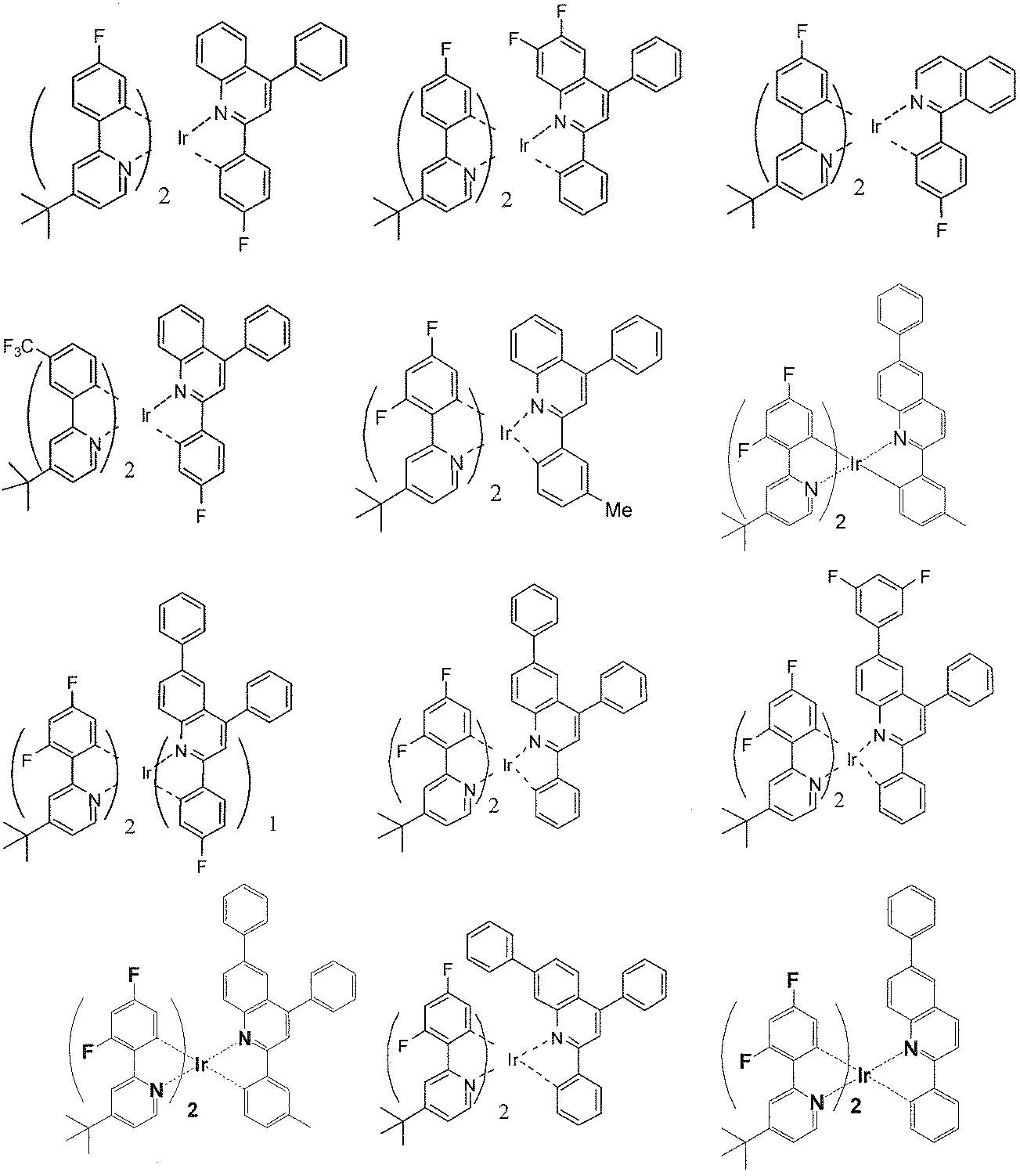
- Example 12 The same procedure as in Example 12 was conducted except that the iridium complex compound (1-a) was changed to the following iridium complex compounds (3-k) to (0-c), and the iridium complex compounds (3-k) to (0- The maximum emission wavelength and emission quantum yield of c) were measured.
- organic EL elements c1 to c6 were prepared in the same manner as in the organic EL element 12 of Example 12, except that the iridium complex compound (1-a) was changed to iridium complex compounds (3-k) to (0-c). Was made. These organic EL elements were also evaluated for light emission characteristics in the same manner as the organic EL element 12. The results are shown in Table 1.
- the iridium complex compounds using phenylpyridyl ligands that do not have an electron-withdrawing substituent have low emission quantum yields, and the luminous efficiency and power efficiency of the devices produced using these compounds
- the iridium complex using the phenylpyridyl ligand introduced with an electron-withdrawing substituent of the present invention has a high emission quantum yield, and the device manufactured using the iridium complex has a high emission quantum yield. It turns out that luminous efficiency and power efficiency are also high.
- the iridium complex compound of the present invention is an aryl group in which at least one of R 20 and R 22 may have a substituent when L 1 is a ligand represented by the formula (3).
- the iridium complex compound of the present invention has an emission quantum yield, High luminous efficiency and power efficiency.
- Examples 23 to 28 11.8 mg of a copolymer obtained by polymerizing the hole transport material represented by the compound (E8) and the electron transport material represented by (E20) at a ratio of 2: 1 (weight ratio), and an iridium complex compound (1-a ) To (3-i) is added to 0.4 g of toluene (Wako Pure Chemical Industries, special grade), and the iridium complex compound (5-a) is further added to the CIE (Commission International de l'Eclairage; International Lighting Commission) Organic EL device produced in the same manner as in Example 12 except that a solution prepared by adding chromaticity at a concentration of [0.45, 0.45] was used. 23 to 28 were produced. These organic EL elements were also evaluated for light emission characteristics in the same manner as the organic EL element 12. The results are shown in Table 2.
- a white light-emitting organic EL device prepared by mixing a blue light-emitting iridium complex (5-a) with a red light-emitting iridium complex using a phenylpyridyl ligand having an electron-withdrawing substituent (Examples 23 to 28). ) Is higher in luminous efficiency and power efficiency than a white light emitting organic EL device (Comparative Examples 7 and 8) prepared using a red light emitting iridium complex using a phenylpyridyl ligand having no electron-withdrawing substituent. I understand.
- Examples 29 to 34 11.8 mg of a copolymer obtained by polymerizing the hole transport material represented by the compound (E8) and the electron transport material represented by (E20) at a ratio of 2: 1 (weight ratio), and an iridium complex compound (1-c ) To (3-i) is added to 0.4 g of toluene (Wako Pure Chemical Industries, Special Grade), and the iridium complex compound (5-b) is added to the CIE (Commission International de l'Eclairage; International Lighting Commission) Organic EL device manufactured in the same manner as in Example 12 except that a solution prepared by adding chromaticity at a concentration of [0.40, 0.40] was used. 29 to 34 were produced. These organic EL elements were also evaluated for light emission characteristics in the same manner as the organic EL element 12. The results are shown in Table 3.
- a white light emitting organic EL device prepared by mixing a blue light emitting iridium complex (5-b) with a red light emitting iridium complex using a phenylpyridyl ligand having an electron withdrawing substituent (Examples 29 to 34). ) Is higher in luminous efficiency and power efficiency than a white light emitting organic EL device (Comparative Example 9) produced using a red light emitting iridium complex using a phenylpyridyl ligand having no electron withdrawing substituent. .
- Substrate 2 Anode 3: Anode buffer layer 4: Light emitting layer 5: Cathode
Abstract
Description
下記式(1)で表されるイリジウム錯体化合物。 [1]
The iridium complex compound represented by following formula (1).


[2]
前記式(1)で表されるイリジウム錯体化合物中のR1~R4で示される置換基のうち、少なくとも2つが、それぞれ独立にフッ素原子、シアノ基、少なくとも一つの水素原子がフッ素原子で置換された炭素数1~10のアルキル基から選択される、[1]に記載のイリジウム錯体化合物。 (R 9 to R 27 are each independently a hydrogen atom, a cyano group, a nitro group, a halogen atom, an optionally substituted alkyl group having 1 to 30 carbon atoms, or an optionally substituted carbon atom having 1 carbon atom. May have an alkylamino group having ˜30, an arylamino group having 6 to 30 carbon atoms which may have a substituent, an alkoxy group having 1 to 30 carbon atoms which may have a substituent, and a substituent. A halogenated alkoxy group having 1 to 30 carbon atoms, an aromatic oxy group having 6 to 30 carbon atoms which may have a substituent, an aryl group having 6 to 40 carbon atoms which may have a substituent, and a substituent; An optionally substituted heterocyclic group having 3 to 30 carbon atoms, an optionally substituted halogenated alkyl group having 1 to 32 carbon atoms, and an optionally substituted alkenyl group having 2 to 30 carbon atoms An alkynyl group having 2 to 30 carbon atoms which may have a substituent, and a carbon number which may have a substituent -30 cycloalkyl group, electron-withdrawing substituent (aldehyde group, acyl group having 2 to 10 carbon atoms, alkoxycarbonyl group having 2 to 10 carbon atoms, aminocarbonyl group having 1 to 10 carbon atoms, thiocyanate group or carbon A sulfonyl group having 1 to 10 carbon atoms), an aralkyl group having 7 to 40 carbon atoms, a silyl group optionally substituted by an alkyl group having 1 to 30 carbon atoms, or at least one of hydrogen atoms of these groups is a fluorine atom However, at least one of R 20 and R 22 is an aryl group which may have a substituent, and adjacent Rs in R 9 to R 27 are bonded to each other to form a ring. You may do it.)
[2]
Among the iridium complex compounds represented by the formula (1), at least two of the substituents represented by R 1 to R 4 are each independently a fluorine atom, a cyano group, and at least one hydrogen atom is substituted with a fluorine atom. The iridium complex compound according to [1], which is selected from alkyl groups having 1 to 10 carbon atoms.
最大発光波長を580~640nmに持つ[1]または[2]に記載のイリジウム錯体化合物。 [3]
The iridium complex compound according to [1] or [2], which has a maximum emission wavelength of 580 to 640 nm.
[1]~[3]のいずれか一項に記載のイリジウム錯体化合物および最大発光波長を450~490nmの波長範囲に有する青色発光性化合物を含む組成物。 [4]
A composition comprising the iridium complex compound according to any one of [1] to [3] and a blue light-emitting compound having a maximum emission wavelength in a wavelength range of 450 to 490 nm.
前記青色発光性化合物が、下記式(4)で表されるイリジウム錯体化合物であり、[1]~[3]のいずれか一項に記載のイリジウム錯体化合物1重量部に対して、下記式(4)で表されるイリジウム錯体化合物を1~100重量部含む、[4]に記載の組成物。 [5]
The blue light-emitting compound is an iridium complex compound represented by the following formula (4), and with respect to 1 part by weight of the iridium complex compound according to any one of [1] to [3], the following formula ( The composition according to [4], comprising 1 to 100 parts by weight of the iridium complex compound represented by 4).

[6]
一対の電極と、発光層を含む一層または複数層の有機層とを備えた有機エレクトロルミネッセンス素子であって、上記発光層が[1]~[3]のいずれか一項に記載のイリジウム錯体化合物あるいは[4]または[5]に記載の組成物を含有することを特徴とする有機エレクトロルミネッセンス素子。 (In the formula (4), R 32 to R 35 are each independently a hydrogen atom, an alkyl group having 1 to 30 carbon atoms, an aryl group having 6 to 40 carbon atoms, an aralkyl group having 7 to 40 carbon atoms, or a carbon number. An amino group optionally substituted by an alkyl group having 1 to 30; an alkoxy group having 1 to 30 carbon atoms; a silyl group optionally substituted by an alkyl group having 1 to 30 carbon atoms; a halogen atom or a cyano group. , And at least one of R 32 to R 35 is a group having 2 or more carbon atoms, R 28 to R 31 are each independently a halogen atom, and at least one hydrogen atom is substituted with a fluorine atom. An alkyl group having 1 to 10 carbon atoms, an alkoxy group having 1 to 10 carbon atoms in which at least one hydrogen atom is substituted with a fluorine atom, a cyano group, an aldehyde group, an acyl group having 2 to 10 carbon atoms, an alkyl group having 2 to 10 carbon atoms An electron-withdrawing substituent selected from a xylcarbonyl group, an aminocarbonyl group having 1 to 10 carbon atoms, a thiocyanate group and a sulfonyl group having 1 to 10 carbon atoms, and an organic compound having 1 to 10 carbon atoms which may have a hetero atom A group (excluding the electron-withdrawing substituent) or a hydrogen atom, and at least one of R 28 to R 31 is the electron-withdrawing substituent.
[6]
An organic electroluminescence device comprising a pair of electrodes and one or more organic layers including a light emitting layer, wherein the light emitting layer is an iridium complex compound according to any one of [1] to [3] Or the composition as described in [4] or [5] is contained, The organic electroluminescent element characterized by the above-mentioned.
前記発光層がさらに電荷輸送性の非共役高分子を含有することを特徴とする[6]に記載の有機エレクトロルミネッセンス素子。 [7]
The organic light-emitting device according to [6], wherein the light-emitting layer further contains a charge-transporting non-conjugated polymer.
[6]または[7]に記載の有機エレクトロルミネッセンス素子を用いたことを特徴とする画像表示装置。 [8]
An image display device using the organic electroluminescence element according to [6] or [7].
[6]または[7]に記載の有機エレクトロルミネッセンス素子を用いたことを特徴とする面発光光源。 [9]
A surface-emitting light source using the organic electroluminescence device according to [6] or [7].
本発明のイリジウム錯体化合物は、下記式(1)で表される。 <Iridium complex compound>
The iridium complex compound of the present invention is represented by the following formula (1).


前述のように、R1~R8において隣接するR同士は互いに結合して環を形成しない。これは環を形成しπ共役が拡張されたイリジウム錯体化合物は発光量子収率が低くなることが知られているためである。また、前述のようにR20とR22の少なくとも一方が置換基を有してもよいアリール基である。これはR20とR22少なくとも一方が置換基を有してもよいアリール基である場合、両方が置換基を有していてもよいアリール基で無い場合と比較して発光量子収率が高くなるからである。 (R 9 to R 27 are each independently a hydrogen atom, a cyano group, a nitro group, a halogen atom, an optionally substituted alkyl group having 1 to 30 carbon atoms, or an optionally substituted carbon atom having 1 carbon atom. May have an alkylamino group having ˜30, an arylamino group having 6 to 30 carbon atoms which may have a substituent, an alkoxy group having 1 to 30 carbon atoms which may have a substituent, and a substituent. A halogenated alkoxy group having 1 to 30 carbon atoms, an aromatic oxy group having 6 to 30 carbon atoms which may have a substituent, an aryl group having 6 to 40 carbon atoms which may have a substituent, and a substituent; An optionally substituted heterocyclic group having 3 to 30 carbon atoms, an optionally substituted halogenated alkyl group having 1 to 32 carbon atoms, and an optionally substituted alkenyl group having 2 to 30 carbon atoms An alkynyl group having 2 to 30 carbon atoms which may have a substituent, and a carbon number which may have a substituent -30 cycloalkyl group, electron-withdrawing substituent (aldehyde group, acyl group having 2 to 10 carbon atoms, alkoxycarbonyl group having 2 to 10 carbon atoms, aminocarbonyl group having 1 to 10 carbon atoms, thiocyanate group or carbon A sulfonyl group having 1 to 10 carbon atoms), an aralkyl group having 7 to 40 carbon atoms, a silyl group optionally substituted by an alkyl group having 1 to 30 carbon atoms, or at least one of hydrogen atoms of these groups is a fluorine atom However, at least one of R 20 and R 22 is an aryl group which may have a substituent, and adjacent Rs in R 9 to R 27 are bonded to each other to form a ring. You may do it.)
As described above, adjacent Rs in R 1 to R 8 are not bonded to each other to form a ring. This is because an iridium complex compound that forms a ring and has an expanded π-conjugate is known to have a low emission quantum yield. Moreover, as described above, at least one of R 20 and R 22 is an aryl group which may have a substituent. This is because when at least one of R 20 and R 22 is an aryl group which may have a substituent, the emission quantum yield is higher than when both are not an aryl group which may have a substituent. Because it becomes.


上述した本発明のイリジウム錯体化合物の製造方法は特に限定されないが、例えば以下の方法で製造することができる。 [Method for producing iridium complex compound]
Although the manufacturing method of the iridium complex compound of this invention mentioned above is not specifically limited, For example, it can manufacture with the following method.

本発明の組成物は、前記イリジウム錯体化合物および最大発光波長を450~490nmの波長範囲に有する青色発光性化合物を含むことを特徴とする。 <Composition>
The composition of the present invention comprises the iridium complex compound and a blue light-emitting compound having a maximum emission wavelength in a wavelength range of 450 to 490 nm.

なお、式(4)における各置換基(炭素数6~40のアリール基、炭素数7~40のアラルキル基等)としては、前記式(1)で例示した各置換基を用いることができる。 (In the formula (4), R 32 to R 35 are each independently a hydrogen atom, an alkyl group having 1 to 30 carbon atoms, an aryl group having 6 to 40 carbon atoms, an aralkyl group having 7 to 40 carbon atoms, or a carbon number. An amino group optionally substituted by an alkyl group having 1 to 30; an alkoxy group having 1 to 30 carbon atoms; a silyl group optionally substituted by an alkyl group having 1 to 30 carbon atoms; a halogen atom or a cyano group. , And at least one of R 32 to R 35 is a group having 2 or more carbon atoms, R 28 to R 31 are each independently a halogen atom, and at least one hydrogen atom is substituted with a fluorine atom. An alkyl group having 1 to 10 carbon atoms, an alkoxy group having 1 to 10 carbon atoms in which at least one hydrogen atom is substituted with a fluorine atom, a cyano group, an aldehyde group, an acyl group having 2 to 10 carbon atoms, an alkyl group having 2 to 10 carbon atoms An electron-withdrawing substituent selected from a xylcarbonyl group, an aminocarbonyl group having 1 to 10 carbon atoms, a thiocyanate group and a sulfonyl group having 1 to 10 carbon atoms, and an organic compound having 1 to 10 carbon atoms which may have a hetero atom A group (excluding the electron-withdrawing substituent) or a hydrogen atom, and at least one of R 28 to R 31 is the electron-withdrawing substituent.
In addition, as each substituent (C6-C40 aryl group, C7-C40 aralkyl group, etc.) in Formula (4), each substituent illustrated by said Formula (1) can be used.
本発明に係る有機EL素子は、基板と、前記基板上に形成された一対の電極と、前記一対の電極間に発光層を含む一層または複数層の有機層とを備えた有機EL素子であって、上記発光層が本発明のイリジウム錯体化合物または本発明の組成物を含有することを特徴とする有機EL素子である。 <Organic EL device>
The organic EL device according to the present invention is an organic EL device comprising a substrate, a pair of electrodes formed on the substrate, and one or more organic layers including a light emitting layer between the pair of electrodes. The organic EL device is characterized in that the light emitting layer contains the iridium complex compound of the present invention or the composition of the present invention.
上記の各層は、バインダとして高分子材料を混合して、形成されていてもよい。上記高分子材料としては、例えば、ポリメチルメタクリレート、ポリカーボネート、ポリエステル、ポリスルホン、ポリフェニレンオキサイドなどが挙げられる。 <Other materials>
Each of the above layers may be formed by mixing a polymer material as a binder. Examples of the polymer material include polymethyl methacrylate, polycarbonate, polyester, polysulfone, and polyphenylene oxide.
上記電荷輸送性の非共役高分子化合物は、ホール輸送性の重合性化合物および電子輸送性の重合性化合物からなる群より選択される少なくとも1種の重合性化合物を含む単量体を共重合して得られる重合体であることが好ましい。なお、本明細書において、ホール輸送性の重合性化合物および電子輸送性の重合性化合物を併せて、電荷輸送性の重合性化合物ともいう。 <Charge transporting non-conjugated polymer compound>
The charge transporting non-conjugated polymer compound is obtained by copolymerizing a monomer containing at least one polymerizable compound selected from the group consisting of a hole transporting polymerizable compound and an electron transporting polymerizable compound. It is preferable that it is a polymer obtained by this. Note that in this specification, the hole transport polymerizable compound and the electron transport polymerizable compound are also collectively referred to as a charge transport polymerizable compound.


本発明に係る有機EL素子は、公知の方法で、マトリックス方式またはセグメント方式による画素として画像表示装置に好適に用いられる。また、上記有機EL素子は、画素を形成せずに、面発光光源としても好適に用いられる。 <Application>
The organic EL device according to the present invention is suitably used in an image display device as a matrix or segment pixel by a known method. The organic EL element is also suitably used as a surface light source without forming pixels.

(イリジウム錯体化合物(1-a)の合成) [Example 1]
(Synthesis of iridium complex compound (1-a))
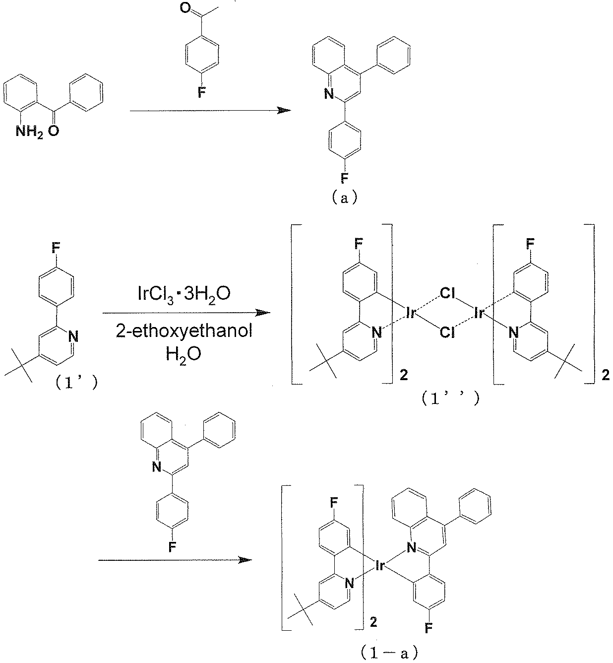
ジムロート氏冷却管と三方コックを備えた50ml二口フラスコに2-アミノベンゾフェノン1.97g、4-フルオロアセトフェノン1.38gを酢酸20ml、硫酸1mlの混合溶媒に溶解させ、4時間還流攪拌した。このあと酢酸エチル20mlを加え一晩放置、キノリン硫酸塩の結晶が晶析しているのでろ過し、酢酸エチルで洗浄した。濾さいをメタノール50mlに加え、ほぼ溶解する。これに1N-NaOH 10mlと水10mlを加える。白く晶析してくるので、ろ過、水洗し化合物(a)を得た。収量(収率)は1.22g(41%)。 <Synthesis of Compound (a)>
In a 50 ml two-necked flask equipped with a Jimroth condenser and a three-way cock, 1.97 g of 2-aminobenzophenone and 1.38 g of 4-fluoroacetophenone were dissolved in a mixed solvent of 20 ml of acetic acid and 1 ml of sulfuric acid and stirred at reflux for 4 hours. Thereafter, 20 ml of ethyl acetate was added, and the mixture was allowed to stand overnight. Since crystals of quinoline sulfate were crystallized, the crystals were filtered and washed with ethyl acetate. The filter cake is added to 50 ml of methanol and almost dissolved. To this is added 10 ml of 1N NaOH and 10 ml of water. Since it crystallized white, the compound (a) was obtained by filtration and washing with water. Yield (yield) was 1.22 g (41%).
ジムロート氏冷却管と三方コックを備えた50ml二口フラスコにPolyhedron 25,1167(2006)と同様の方法で合成した2-(4’-フルオロフェニル)-4-ターシャリーブチルピリジン371mg、塩化イリジウム(III)三水和物212mg、2-エトキシエタノール9ml、純水3mlを加え、得られた溶液に5分間窒素をバブリングした後、窒素下において14時間攪拌しながら還流し、これらを反応させた。反応後、室温まで冷却し、純水30mlを加えて生成物を沈殿させた。沈殿物をろ取し、メタノール/水=7/3の混合溶媒50mlで洗浄した後、減圧下で乾燥して化合物(1’)を黄色の粉末として得た。収量(収率)は367mg(85%)。 <Synthesis of Compound (1 ')>
371 mg of 2- (4′-fluorophenyl) -4-tertiarybutylpyridine synthesized in the same manner as Polyhedron 25,1167 (2006) in a 50 ml two-necked flask equipped with a Jimroth condenser and a three-way cock, iridium chloride ( III) 212 mg of trihydrate, 9 ml of 2-ethoxyethanol and 3 ml of pure water were added, and the resulting solution was bubbled with nitrogen for 5 minutes, and then refluxed with stirring for 14 hours under nitrogen to react them. After the reaction, the mixture was cooled to room temperature, and 30 ml of pure water was added to precipitate the product. The precipitate was collected by filtration, washed with 50 ml of a mixed solvent of methanol / water = 7/3, and then dried under reduced pressure to obtain compound (1 ′) as a yellow powder. Yield (yield) was 367 mg (85%).
ジムロート氏冷却管と三方コックを備えた50ml二口フラスコに化合物(1’)200mg(0.29mmol)、化合物(a)131mg(0.36mmol)、炭酸カリウム(120mg、0.87mmol)を加え窒素置換した。脱水メシチレン(6ml)、トリフルオロメタンスルホン酸銀(I)(96mg、0.38mmol)を加えた後、1時間20分攪拌しながら還流して反応させた。反応後、室温まで冷却し、クロロホルムを加えセライトを用いてろ過した。シリカゲルカラムクロマトグラフィーを用いて精製した。メタノールを加え超音波にかけたところ結晶化したので、これをろ過し、乾燥することでイリジウム錯体化合物(1-a)を赤色の微結晶として得た。収量(収率)は38mg(14%)。 <Synthesis of Compound (1-a)>
To a 50 ml two-necked flask equipped with a Jimroth condenser tube and a three-way cock, 200 mg (0.29 mmol) of compound (1 ′), 131 mg (0.36 mmol) of compound (a), potassium carbonate (120 mg, 0.87 mmol) were added, and nitrogen was added. Replaced. After adding dehydrated mesitylene (6 ml) and silver (I) trifluoromethanesulfonate (96 mg, 0.38 mmol), the mixture was reacted by refluxing with stirring for 1 hour and 20 minutes. After the reaction, the mixture was cooled to room temperature, chloroform was added, and the mixture was filtered through celite. Purification was performed using silica gel column chromatography. When methanol was added and sonicated, it crystallized. This was filtered and dried to obtain iridium complex compound (1-a) as red microcrystals. Yield (yield) was 38 mg (14%).
(イリジウム錯体化合物(1-b)の合成)
2-アミノベンゾフェノンを2-アミノー4,5-ジフルオロベンゾフェノンに代え、4-フルオロアセトフェノンを4-アセトフェノンに代えて用い、イリジウム錯体化合物(1-a)と同様の方法で合成し、イリジウム錯体化合物(1-b)を得た。 [Example 2]
(Synthesis of iridium complex compound (1-b))
Using 2-aminobenzophenone in place of 2-amino-4,5-difluorobenzophenone and 4-fluoroacetophenone in place of 4-acetophenone, synthesis was performed in the same manner as iridium complex compound (1-a), and iridium complex compound ( 1-b) was obtained.
(イリジウム錯体化合物(1-c)の合成)
<化合物(c)の合成> [Example 3]
(Synthesis of iridium complex compound (1-c))
<Synthesis of Compound (c)>

化合物(a)を化合物(c)に代えて用い、イリジウム錯体化合物(1―a)と同様の方法で合成しイリジウム錯体化合物(1-c)を得た。 <Synthesis of Compound (1-c)>
Compound (a) was used in place of compound (c) and synthesized in the same manner as iridium complex compound (1-a) to obtain iridium complex compound (1-c).
(イリジウム錯体化合物(2-a)の合成)
化合物(1’)を、Polyhedron 25,1167(2006)と同様の方法で合成した2-(3’-トリフルオロメチルフェニル)-4-ターシャリーブチルピリジンに代えて用い、イリジウム錯体化合物(1-a)と同様の方法で合成しイリジウム錯体化合物(2-a)を得た。 [Example 4]
(Synthesis of iridium complex compound (2-a))
Compound (1 ′) was used in place of 2- (3′-trifluoromethylphenyl) -4-tertiarybutylpyridine synthesized in the same manner as Polyhedron 25,1167 (2006), and iridium complex compound (1- Synthesis was performed in the same manner as in a) to obtain an iridium complex compound (2-a).
(イリジウム錯体化合物(3-d)の合成)
<化合物(d)の合成> [Example 5]
(Synthesis of iridium complex compound (3-d))
<Synthesis of Compound (d)>

<化合物(3-d)の合成>
化合物(1’)を、Polyhedron 25,1167(2006)と同様の方法で合成した2-(2’,4’-ジフルオロフェニル)-4-ターシャリーブチルピリジン(3’)に代え、化合物(a)を化合物(d)に代えて用い、イリジウム錯体化合物(1-a)と同様の方法で合成しイリジウム錯体化合物(3-d)を得た。 Using 4-fluoroacetophenone instead of 3-methylacetophenone, compound (d) was synthesized in the same manner as compound (a).
<Synthesis of Compound (3-d)>
The compound (1 ′) was replaced with 2- (2 ′, 4′-difluorophenyl) -4-tertiarybutylpyridine (3 ′) synthesized by the same method as Polyhedron 25,1167 (2006), and the compound (a ) Was used in place of compound (d) and synthesized in the same manner as iridium complex compound (1-a) to obtain iridium complex compound (3-d).
(イリジウム錯体化合物(3-e)の合成) [Example 6]
(Synthesis of iridium complex compound (3-e))

6-ブロモアニリン 2.1g(10mmol)、フェニルボロン酸1.2g(10mmol)、炭酸カリウム2.8g(20mmol)、テトラキストリフェニルホスフィンパラジウム(0)1.1g(1mmol)、を1,2-ジメトキシエタン40ml、水20mlの混合溶媒中に溶解させ、窒素雰囲気下3時間還流攪拌し反応させた。反応後、室温まで冷却しトルエン40mlを加え水層を除去した。シリカゲルカラムクロマトグラフィーを用いて精製し化合物(e1)を得た。収量1.64g(80%)。 <Synthesis of Compound (e1)>
2.1 g (10 mmol) of 6-bromoaniline, 1.2 g (10 mmol) of phenylboronic acid, 2.8 g (20 mmol) of potassium carbonate, 1.1 g (1 mmol) of tetrakistriphenylphosphine palladium (0), The resultant was dissolved in a mixed solvent of 40 ml of dimethoxyethane and 20 ml of water, and reacted by stirring under reflux in a nitrogen atmosphere for 3 hours. After the reaction, the mixture was cooled to room temperature, 40 ml of toluene was added, and the aqueous layer was removed. Purification was performed using silica gel column chromatography to obtain compound (e1). Yield 1.64 g (80%).
6-フェニルキノリン(化合物(e1))1.64g(8.0mmol)、酢酸10ml、30%過酸化水素水2mlを加え80℃で3時間攪拌した。反応後水酸化ナトリウム水溶液で洗浄した。アルミナカラムクロマトグラフィーで精製し化合物(e2)を得た。収量1.70g(96%)。 <Synthesis of Compound (e2)>
1.64 g (8.0 mmol) of 6-phenylquinoline (compound (e1)), 10 ml of acetic acid and 2 ml of 30% hydrogen peroxide solution were added and stirred at 80 ° C. for 3 hours. After the reaction, it was washed with an aqueous sodium hydroxide solution. Purification by alumina column chromatography gave compound (e2). Yield 1.70 g (96%).
6―フェニルキノリン-N-オキサイド(化合物(e2))1.70g(7.7mmol)をクロロホルム5mlに溶解させ、オキシ塩化リン5.9g(39.5mmol)をゆっくり加えた後、窒素下15時間還流攪拌した。反応後水酸化ナトリウム水溶液で中和した。シリカゲルカラムクロマトグラフィーで精製し化合物(e3)を得た。収量1.1g(60%)。 <Synthesis of Compound (e3)>
1.70 g (7.7 mmol) of 6-phenylquinoline-N-oxide (compound (e2)) is dissolved in 5 ml of chloroform, and 5.9 g (39.5 mmol) of phosphorus oxychloride is slowly added thereto, followed by 15 hours under nitrogen. Stir at reflux. After the reaction, it was neutralized with an aqueous sodium hydroxide solution. Purification by silica gel column chromatography gave compound (e3). Yield 1.1 g (60%).
2-クロロ-6-フェニルキノリン(化合物(e3))1.1g(4.6mmol)、m-メチルフェニルボロン酸0.63g(4.6mmol)、炭酸カリウムg1.3g(9.2mmol)、テトラキストリフェニルホスフィンパラジウム(0)0.23g(0.2mmol)、を1,2-ジメトキシエタン40ml、水20mlの混合溶媒中に溶解させ、窒素雰囲気下3時間還流攪拌し反応させた。反応後、室温まで冷却しトルエン40mlを加え水層を除去した。シリカゲルカラムクロマトグラフィーを用いて精製し化合物(e)を得た。収量0.65g(48%)。 <Synthesis of Compound (e4)>
1.1 g (4.6 mmol) of 2-chloro-6-phenylquinoline (compound (e3)), 0.63 g (4.6 mmol) of m-methylphenylboronic acid, 1.3 g (9.2 mmol) of potassium carbonate, tetrakis 0.23 g (0.2 mmol) of triphenylphosphine palladium (0) was dissolved in a mixed solvent of 40 ml of 1,2-dimethoxyethane and 20 ml of water, and the mixture was reacted by stirring under reflux for 3 hours under a nitrogen atmosphere. After the reaction, the mixture was cooled to room temperature, 40 ml of toluene was added, and the aqueous layer was removed. Purification was performed using silica gel column chromatography to obtain compound (e). Yield 0.65 g (48%).
化合物(d)を化合物(e)に代えて用い、イリジウム錯体化合物(3―d)と同様の方法で合成しイリジウム錯体化合物(3-e)を得た。 <Synthesis of Compound (3-e)>
Compound (d) was used in place of compound (e) and synthesized in the same manner as iridium complex compound (3-d) to obtain iridium complex compound (3-e).
(イリジウム錯体化合物(3-f)の合成) [Example 7]
(Synthesis of iridium complex compound (3-f))

アミノベンゾフェノン4.0g、ヨウ化カリウム2.2g、ヨウ素酸1.4gをメタノール20ml、水100mlの混合溶媒中で攪拌しながら室温で1N-HCl20mlを加え出滴下する。一晩放置後、クロロホルム30mlを加え抽出した。亜硫酸ナトリウム水溶液で洗浄、さらに2回水洗した。硫酸マグネシウムで乾燥後、ろ過し溶媒を減圧留居した。メタノール30mlを加え加熱したあと、水3mlを加え晶析させた。ろ過後、メタノールと水で洗浄し固体状の化合物(f1)を得た。収量4.0g(60%)。 <Synthesis of Compound (f1)>
While stirring 4.0 g of aminobenzophenone, 2.2 g of potassium iodide and 1.4 g of iodic acid in a mixed solvent of 20 ml of methanol and 100 ml of water, 20 ml of 1N HCl is added at room temperature and added dropwise. After leaving overnight, 30 ml of chloroform was added for extraction. It was washed with an aqueous sodium sulfite solution and further washed twice with water. After drying over magnesium sulfate, the mixture was filtered and the solvent was retained under reduced pressure. After adding 30 ml of methanol and heating, 3 ml of water was added for crystallization. After filtration, it was washed with methanol and water to obtain a solid compound (f1). Yield 4.0 g (60%).
化合物(f1)2.0g、4-フルオロアセトフェノン1.0gを酢酸12ml、硫酸0.6mlに溶解させ、120度で5時間加熱攪拌した。その後酢酸エチル12mlを加え一晩放置した後、ろ過し酢酸エチルで洗浄した。これをメタノール20mlに懸濁させ1N-NaOH12mlを加え中和した。ろ過し、水、メタノールで洗浄し化合物(f2)を得た。収量1.7g(46%)。 <Synthesis of Compound (f2)>
Compound (f1) (2.0 g) and 4-fluoroacetophenone (1.0 g) were dissolved in acetic acid (12 ml) and sulfuric acid (0.6 ml), and the mixture was heated and stirred at 120 ° C. for 5 hours. Thereafter, 12 ml of ethyl acetate was added and the mixture was allowed to stand overnight, then filtered and washed with ethyl acetate. This was suspended in 20 ml of methanol and neutralized by adding 12 ml of 1N NaOH. Filtration and washing with water and methanol gave compound (f2). Yield 1.7 g (46%).
化合物(f2)1.67g、フェニルボロン酸5.58g、2M炭酸カリウム水溶液4ml、テトラキストリフェニルホスフィンパラジウム(0)90mgを1,2-ジメトキシエタン12mlに溶解させ窒素雰囲気下4時間還流攪拌し反応させた。反応後、室温まで冷却しトルエン20mlを加え水層を除去した。シリカゲルカラムクロマトグラフィーを用いて精製し化合物(f)を得た。収量1.03g(68%)。 <Synthesis of Compound (f)>
1.67 g of compound (f2), 5.558 g of phenylboronic acid, 4 ml of 2M aqueous potassium carbonate solution and 90 mg of tetrakistriphenylphosphine palladium (0) are dissolved in 12 ml of 1,2-dimethoxyethane, and the mixture is stirred under reflux for 4 hours under a nitrogen atmosphere. I let you. After the reaction, the mixture was cooled to room temperature, 20 ml of toluene was added, and the aqueous layer was removed. The product was purified by silica gel column chromatography to obtain compound (f). Yield 1.03 g (68%).
化合物(d)を化合物(f)に代えて用い、イリジウム錯体化合物(3―d)と同様の方法で合成しイリジウム錯体化合物(3-f)を得た。 <Synthesis of Compound (3-f)>
Compound (d) was used in place of compound (f), and synthesized in the same manner as iridium complex compound (3-d) to obtain iridium complex compound (3-f).
(イリジウム錯体化合物(3-g)の合成)
4-フルオロアセトフェノンをアセトフェノンに代えて用い、それ以外は実施例7と同様の方法で合成しイリジウム錯体化合物(3-g)を得た。 [Example 8]
(Synthesis of iridium complex compound (3-g))
4-Fluoroacetophenone was used instead of acetophenone, and the others were synthesized in the same manner as in Example 7 to obtain an iridium complex compound (3-g).
(イリジウム錯体化合物(3-h)の合成)
4-フルオロアセトフェノンをアセトフェノンに、フェニルボロン酸を3,5-ジフルオロフェニルボロン酸に代えて用い、それ以外は実施例7と同様の方法で合成しイリジウム錯体化合物(3-h)を得た。 [Example 9]
(Synthesis of iridium complex compound (3-h))
Synthesis was performed in the same manner as in Example 7 except that 4-fluoroacetophenone was used in place of acetophenone and phenylboronic acid was used in place of 3,5-difluorophenylboronic acid to obtain an iridium complex compound (3-h).
(イリジウム錯体化合物(3-i)の合成)
4-フルオロアセトフェノンを、3-メチルアセトフェノンに代えて用い、それ以外は実施例7と同様の方法で合成しイリジウム錯体化合物(3-i)を得た。 [Example 10]
(Synthesis of iridium complex compound (3-i))
4-Fluoroacetophenone was used in place of 3-methylacetophenone and the others were synthesized in the same manner as in Example 7 to obtain an iridium complex compound (3-i).
(イリジウム錯体化合物(3-j)の合成) [Example 11]
(Synthesis of iridium complex compound (3-j))

3-アミノビフェニル2.06g、ベンズアルデヒド1.06gを混合し、60℃で1時間加熱攪拌し化合物(j1)を得た。これに塩化ルテニウム80mg、臭化銅0.43g、フェニルアセチレン1.2gを加え60℃で2.5時間加熱攪拌した。シリカゲルカラムクロマトグラフィーで精製し化合物(j2)を得た。収量は3.43g(96%)。 <Synthesis of Compounds (j1) and (j2)>
2.06 g of 3-aminobiphenyl and 1.06 g of benzaldehyde were mixed, and the mixture was heated and stirred at 60 ° C. for 1 hour to obtain compound (j1). To this, 80 mg of ruthenium chloride, 0.43 g of copper bromide and 1.2 g of phenylacetylene were added and stirred with heating at 60 ° C. for 2.5 hours. Purification by silica gel column chromatography gave compound (j2). Yield 3.43 g (96%).
化合物(j2)1.0g、塩化金(III)42mgをメタノール30mlに溶解させ、50℃で5時間攪拌した。溶媒を減圧留去したのち、シリカゲルカラムクロマトグラフィーで精製し化合物(j)を得た。収量は0.62g(62%)。 <Synthesis of Compound (j)>
1.0 g of compound (j2) and 42 mg of gold (III) chloride were dissolved in 30 ml of methanol and stirred at 50 ° C. for 5 hours. After evaporating the solvent under reduced pressure, the residue was purified by silica gel column chromatography to obtain compound (j). Yield 0.62 g (62%).
化合物(d)を化合物(j)に代えて用い、イリジウム錯体化合物(3―d)と同様の方法で合成しイリジウム錯体化合物(3-j)を得た。 <Synthesis of Compound (3-j)>
Compound (d) was used in place of compound (j), and synthesized in the same manner as iridium complex compound (3-d) to obtain iridium complex compound (3-j).
<最大発光波長の評価>
日本分光(JASCO)製 蛍光分光光度計FP―6500を用い、イリジウム錯体化合物(1-a)をクロロホルムに溶解させることで得られた溶液を測定することにより得た。評価結果を表1に示す。 [Example 12]
<Evaluation of maximum emission wavelength>
It was obtained by measuring a solution obtained by dissolving the iridium complex compound (1-a) in chloroform using a fluorescence spectrophotometer FP-6500 manufactured by JASCO. The evaluation results are shown in Table 1.
浜松ホトニクス社製 絶対発光量子収率測定装置C9920-02Gを用い、イリジウム錯体化合物(1-a)を1,2-ジクロロエタンに溶解させることで得られた溶液を測定することにより得た。評価結果を表1に示す。 <Evaluation of luminescence quantum yield>
It was obtained by measuring a solution obtained by dissolving the iridium complex compound (1-a) in 1,2-dichloroethane using an absolute luminescence quantum yield measuring device C9920-02G manufactured by Hamamatsu Photonics. The evaluation results are shown in Table 1.
25mm角のガラス基板の一方の面に、陽極としての幅4mmの2本のITO電極がストライプ状に形成されたITO(酸化インジウム錫)膜付ガラス基板(ニッポ電機、Nippo Electric Co., LTD.)を用いて有機EL素子を作製した。 <Production of organic EL element>
A glass substrate with an ITO (indium tin oxide) film in which two ITO electrodes with a width of 4 mm as an anode are formed on one surface of a 25 mm square glass substrate (Nippo Electric Co., Ltd.) ) Was used to produce an organic EL device.
有機EL素子に定電圧電源(Keithley製、SM2400)を用いて段階的に電圧を印加し、有機EL素子の輝度を輝度計(トプコン製、BM-9)で定量した。電流密度に対する輝度の比から決定した発光効率と電力効率を表1に示す。 <EL emission characteristic evaluation>
A voltage was applied stepwise to the organic EL element using a constant voltage power supply (Keithley, SM2400), and the luminance of the organic EL element was quantified with a luminance meter (Topcon, BM-9). Table 1 shows the luminous efficiency and power efficiency determined from the ratio of luminance to current density.
イリジウム錯体化合物(1-a)を、実施例2~11のイリジウム錯体化合物(1-b)~(3-j)に変更した以外は実施例12と同様に行い、イリジウム錯体化合物(1-b)~(3-j)の最大発光波長、発光量子収率を測定した。 [Examples 13 to 22]
The same procedure as in Example 12 was conducted except that the iridium complex compound (1-a) was changed to the iridium complex compounds (1-b) to (3-j) in Examples 2 to 11, and the iridium complex compound (1-b) ) To (3-j) were measured for maximum emission wavelength and emission quantum yield.
イリジウム錯体化合物(1-a)を、下記イリジウム錯体化合物(3-k)~(0-c)に変更した以外は実施例12と同様に行い、イリジウム錯体化合物(3-k)~(0-c)の最大発光波長、発光量子収率を測定した。 [Comparative Examples 1 to 6]
The same procedure as in Example 12 was conducted except that the iridium complex compound (1-a) was changed to the following iridium complex compounds (3-k) to (0-c), and the iridium complex compounds (3-k) to (0- The maximum emission wavelength and emission quantum yield of c) were measured.


化合物(E8)で表される正孔輸送材料と(E20)で表される電子輸送材料を2:1(重量比)で重合させた共重合体 11.8mgと、イリジウム錯体化合物(1-a)~(3-i)のいずれか0.4mgをトルエン(和光純薬工業、特級)0.4gに加え、さらにイリジウム錯体化合物(5-a)を素子の発光色度がCIE(Commission International de l'Eclairage;国際照明委員会)色度が[0.45、0.45]となるような濃度で加えて調製した溶液を用いた以外は実施例12と同様の方法で作製した有機EL素子23~28を作製した。これらの有機EL素子についても有機EL素子12と同様に発光特性の評価を行った。結果を表2に示す。 [Examples 23 to 28]
11.8 mg of a copolymer obtained by polymerizing the hole transport material represented by the compound (E8) and the electron transport material represented by (E20) at a ratio of 2: 1 (weight ratio), and an iridium complex compound (1-a ) To (3-i) is added to 0.4 g of toluene (Wako Pure Chemical Industries, special grade), and the iridium complex compound (5-a) is further added to the CIE (Commission International de l'Eclairage; International Lighting Commission) Organic EL device produced in the same manner as in Example 12 except that a solution prepared by adding chromaticity at a concentration of [0.45, 0.45] was used. 23 to 28 were produced. These organic EL elements were also evaluated for light emission characteristics in the same manner as the organic EL element 12. The results are shown in Table 2.

イリジウム錯体化合物(1-a)~(3-i)を、イリジウム錯体化合物(4-a)、(4-f)に代えて用いた以外は、実施例23~28と同様な方法で行い、有機EL素子c7、c8を作製した。これらの有機EL素子についても有機EL素子12と同様に発光特性の評価を行った。結果を表2に示す。 [Comparative Examples 7 and 8]
Except that the iridium complex compounds (1-a) to (3-i) were used in place of the iridium complex compounds (4-a) and (4-f), the same procedure as in Examples 23 to 28 was performed. Organic EL elements c7 and c8 were produced. These organic EL elements were also evaluated for light emission characteristics in the same manner as the organic EL element 12. The results are shown in Table 2.

化合物(E8)で表される正孔輸送材料と(E20)で表される電子輸送材料を2:1(重量比)で重合させた共重合体 11.8mgと、イリジウム錯体化合物(1-c)~(3-i)のいずれか0.4mgをトルエン(和光純薬工業、特級)0.4gに加え、さらにイリジウム錯体化合物(5-b)を素子の発光色度がCIE(Commission International de l'Eclairage;国際照明委員会)色度が[0.40、0.40]となるような濃度で加えて調製した溶液を用いた以外は実施例12と同様の方法で作製した有機EL素子29~34を作製した。これらの有機EL素子についても有機EL素子12と同様に発光特性の評価を行った。結果を表3に示す。 [Examples 29 to 34]
11.8 mg of a copolymer obtained by polymerizing the hole transport material represented by the compound (E8) and the electron transport material represented by (E20) at a ratio of 2: 1 (weight ratio), and an iridium complex compound (1-c ) To (3-i) is added to 0.4 g of toluene (Wako Pure Chemical Industries, Special Grade), and the iridium complex compound (5-b) is added to the CIE (Commission International de l'Eclairage; International Lighting Commission) Organic EL device manufactured in the same manner as in Example 12 except that a solution prepared by adding chromaticity at a concentration of [0.40, 0.40] was used. 29 to 34 were produced. These organic EL elements were also evaluated for light emission characteristics in the same manner as the organic EL element 12. The results are shown in Table 3.

イリジウム錯体化合物(1-c)~(3-i)を、イリジウム錯体化合物(4-b)に代えて用いた以外は、実施例29~34と同様な方法で行い、有機EL素子c9を作製した。これらの有機EL素子についても有機EL素子12と同様に発光特性の評価を行った。結果を表3に示す。 [Comparative Example 9]
The organic EL device c9 was produced in the same manner as in Examples 29 to 34 except that the iridium complex compounds (1-c) to (3-i) were used in place of the iridium complex compound (4-b). did. These organic EL elements were also evaluated for light emission characteristics in the same manner as the organic EL element 12. The results are shown in Table 3.

2:陽極
3:陽極バッファ層
4:発光層
5:陰極 1: Substrate 2: Anode 3: Anode buffer layer 4: Light emitting layer 5: Cathode
Claims (9)
- 下記式(1)で表されるイリジウム錯体化合物。


- 前記式(1)で表されるイリジウム錯体化合物中のR1~R4で示される置換基のうち、少なくとも2つが、それぞれ独立にフッ素原子、シアノ基、少なくとも一つの水素原子がフッ素原子で置換された炭素数1~10のアルキル基から選択される、請求項1に記載のイリジウム錯体化合物。 Among the iridium complex compounds represented by the formula (1), at least two of the substituents represented by R 1 to R 4 are each independently a fluorine atom, a cyano group, and at least one hydrogen atom is substituted with a fluorine atom. The iridium complex compound according to claim 1, wherein the iridium complex compound is selected from alkyl groups having 1 to 10 carbon atoms.
- 最大発光波長を580~640nmに持つ請求項1または2に記載のイリジウム錯体化合物。 3. The iridium complex compound according to claim 1, having a maximum emission wavelength of 580 to 640 nm.
- 請求項1~3のいずれか一項に記載のイリジウム錯体化合物および最大発光波長を450~490nmの波長範囲に有する青色発光性化合物を含む組成物。 A composition comprising the iridium complex compound according to any one of claims 1 to 3 and a blue light-emitting compound having a maximum emission wavelength in a wavelength range of 450 to 490 nm.
- 前記青色発光性化合物が、下記式(4)で表されるイリジウム錯体化合物であり、請求項1~3のいずれか一項に記載のイリジウム錯体化合物1重量部に対して、下記式(4)で表されるイリジウム錯体化合物を1~100重量部含む、請求項4に記載の組成物。

- 一対の電極と、発光層を含む一層または複数層の有機層とを備えた有機エレクトロルミネッセンス素子であって、上記発光層が請求項1~3のいずれか一項に記載のイリジウム錯体化合物あるいは請求項4または5に記載の組成物を含有することを特徴とする有機エレクトロルミネッセンス素子。 An organic electroluminescence device comprising a pair of electrodes and a single layer or a plurality of organic layers including a light emitting layer, wherein the light emitting layer is an iridium complex compound according to any one of claims 1 to 3. Item 6. An organic electroluminescence device comprising the composition according to item 4 or 5.
- 前記発光層がさらに電荷輸送性の非共役高分子を含有することを特徴とする請求項6に記載の有機エレクトロルミネッセンス素子。 The organic electroluminescent element according to claim 6, wherein the light emitting layer further contains a non-conjugated polymer having a charge transporting property.
- 請求項6または7に記載の有機エレクトロルミネッセンス素子を用いたことを特徴とする画像表示装置。 An image display device using the organic electroluminescence element according to claim 6 or 7.
- 請求項6または7に記載の有機エレクトロルミネッセンス素子を用いたことを特徴とする面発光光源。 A surface-emitting light source using the organic electroluminescence element according to claim 6 or 7.
Priority Applications (4)
| Application Number | Priority Date | Filing Date | Title |
|---|---|---|---|
| US13/512,568 US20120235132A1 (en) | 2009-11-30 | 2010-11-26 | Iridium complex compound, organic electroluminescent element, and uses thereof |
| JP2011543304A JP5723292B2 (en) | 2009-11-30 | 2010-11-26 | Iridium complex compound, organic electroluminescence device and use thereof |
| EP10833300.6A EP2508527B1 (en) | 2009-11-30 | 2010-11-26 | Iridium complex compound, organic electroluminescence element, and uses thereof |
| CN201080054118.2A CN102648203B (en) | 2009-11-30 | 2010-11-26 | Iridium complex, organic electroluminescent device and uses thereof |
Applications Claiming Priority (2)
| Application Number | Priority Date | Filing Date | Title |
|---|---|---|---|
| JP2009-272909 | 2009-11-30 | ||
| JP2009272909 | 2009-11-30 |
Publications (1)
| Publication Number | Publication Date |
|---|---|
| WO2011065454A1 true WO2011065454A1 (en) | 2011-06-03 |
Family
ID=44066558
Family Applications (1)
| Application Number | Title | Priority Date | Filing Date |
|---|---|---|---|
| PCT/JP2010/071077 WO2011065454A1 (en) | 2009-11-30 | 2010-11-26 | Iridium complex compound, organic electroluminescence element, and use therefor |
Country Status (6)
| Country | Link |
|---|---|
| US (1) | US20120235132A1 (en) |
| EP (1) | EP2508527B1 (en) |
| JP (1) | JP5723292B2 (en) |
| CN (1) | CN102648203B (en) |
| TW (1) | TWI523932B (en) |
| WO (1) | WO2011065454A1 (en) |
Cited By (3)
| Publication number | Priority date | Publication date | Assignee | Title |
|---|---|---|---|---|
| US20140209873A1 (en) * | 2013-01-30 | 2014-07-31 | Soung-Wook KIM | Organometallic complex and organic light-emitting diode including the same |
| JP2014234360A (en) * | 2013-05-31 | 2014-12-15 | 三菱化学株式会社 | Iridium complex compound, organic electroluminescent element, display device and illumination device |
| JP2016069379A (en) * | 2014-09-26 | 2016-05-09 | 三星電子株式会社Samsung Electronics Co.,Ltd. | Organometallic compound and organic light-emitting device including the same |
Families Citing this family (2)
| Publication number | Priority date | Publication date | Assignee | Title |
|---|---|---|---|---|
| KR20190016867A (en) * | 2017-08-09 | 2019-02-19 | 삼성전자주식회사 | Organometallic compound and organic light emitting device the same |
| JP2021178798A (en) * | 2020-05-15 | 2021-11-18 | キヤノン株式会社 | Composition containing iridium complex, organic light-emitting element therewith, display device, imaging device, electronic instrument, lighting device, and movable body |
Citations (10)
| Publication number | Priority date | Publication date | Assignee | Title |
|---|---|---|---|---|
| JPH08157575A (en) | 1994-12-07 | 1996-06-18 | Toppan Printing Co Ltd | Carrier transport polymer |
| JPH101665A (en) | 1996-06-18 | 1998-01-06 | Toyota Central Res & Dev Lab Inc | Electric field light-emitting element |
| JP2001247859A (en) | 1999-12-27 | 2001-09-14 | Fuji Photo Film Co Ltd | Luminescent element material comprising ortho metallized iridium complex, luminescent element and novel iridium complex |
| JP2003526876A (en) | 1999-05-13 | 2003-09-09 | ザ、トラスティーズ オブ プリンストン ユニバーシティ | High efficiency organic light emitting device based on electrophosphorescence |
| JP2006513278A (en) | 2002-08-16 | 2006-04-20 | ザ ユニバーシティ オブ サザン カリフォルニア | Organic light emitting materials and devices |
| JP2006151888A (en) * | 2004-11-30 | 2006-06-15 | Canon Inc | Metal complex, light emitting device and image display device |
| US20080269491A1 (en) * | 2007-02-13 | 2008-10-30 | Arizona Board Of Regents For And On Behalf Of Arizona State University | Organometallic Materials for Optical Emission, Optical Absorption, and Devices Including Organometallic Materials |
| JP2009023938A (en) * | 2007-07-19 | 2009-02-05 | Showa Denko Kk | Iridium complex compound, organic electroluminescent device and use thereof |
| JP2009132688A (en) * | 2007-10-25 | 2009-06-18 | Gracel Display Inc | New red-colored electroluminescent compound and organic electroluminescent device using the same |
| JP2009185017A (en) * | 2007-11-27 | 2009-08-20 | Gracel Display Inc | New organic electroluminescent compound, and organic electroluminescent device using the same |
Family Cites Families (7)
| Publication number | Priority date | Publication date | Assignee | Title |
|---|---|---|---|---|
| US7306856B2 (en) * | 2000-07-17 | 2007-12-11 | Fujifilm Corporation | Light-emitting element and iridium complex |
| EP1348711B1 (en) * | 2000-11-30 | 2018-06-13 | Canon Kabushiki Kaisha | Luminescent element and display |
| DE60239198D1 (en) * | 2001-05-16 | 2011-03-31 | Univ Princeton | HIGHLY EFFICIENT MULTI-COLORED ELECTROPHOSPHORESCENT OLEDS |
| DE10345572A1 (en) * | 2003-09-29 | 2005-05-19 | Covion Organic Semiconductors Gmbh | metal complexes |
| KR101073232B1 (en) * | 2006-11-07 | 2011-10-12 | 쇼와 덴코 가부시키가이샤 | Iridium complex compound, organic electroluminescent device obtained by using the same, and uses of the device |
| WO2009034987A1 (en) * | 2007-09-14 | 2009-03-19 | Showa Denko K.K. | Phosphorescent polymer compound and organic electroluminescent device using the same |
| KR100933226B1 (en) * | 2007-11-20 | 2009-12-22 | 다우어드밴스드디스플레이머티리얼 유한회사 | Novel red phosphorescent compound and organic light emitting device employing it as light emitting material |
-
2010
- 2010-11-26 US US13/512,568 patent/US20120235132A1/en not_active Abandoned
- 2010-11-26 CN CN201080054118.2A patent/CN102648203B/en not_active Expired - Fee Related
- 2010-11-26 WO PCT/JP2010/071077 patent/WO2011065454A1/en active Application Filing
- 2010-11-26 JP JP2011543304A patent/JP5723292B2/en active Active
- 2010-11-26 EP EP10833300.6A patent/EP2508527B1/en not_active Not-in-force
- 2010-11-30 TW TW099141465A patent/TWI523932B/en active
Patent Citations (10)
| Publication number | Priority date | Publication date | Assignee | Title |
|---|---|---|---|---|
| JPH08157575A (en) | 1994-12-07 | 1996-06-18 | Toppan Printing Co Ltd | Carrier transport polymer |
| JPH101665A (en) | 1996-06-18 | 1998-01-06 | Toyota Central Res & Dev Lab Inc | Electric field light-emitting element |
| JP2003526876A (en) | 1999-05-13 | 2003-09-09 | ザ、トラスティーズ オブ プリンストン ユニバーシティ | High efficiency organic light emitting device based on electrophosphorescence |
| JP2001247859A (en) | 1999-12-27 | 2001-09-14 | Fuji Photo Film Co Ltd | Luminescent element material comprising ortho metallized iridium complex, luminescent element and novel iridium complex |
| JP2006513278A (en) | 2002-08-16 | 2006-04-20 | ザ ユニバーシティ オブ サザン カリフォルニア | Organic light emitting materials and devices |
| JP2006151888A (en) * | 2004-11-30 | 2006-06-15 | Canon Inc | Metal complex, light emitting device and image display device |
| US20080269491A1 (en) * | 2007-02-13 | 2008-10-30 | Arizona Board Of Regents For And On Behalf Of Arizona State University | Organometallic Materials for Optical Emission, Optical Absorption, and Devices Including Organometallic Materials |
| JP2009023938A (en) * | 2007-07-19 | 2009-02-05 | Showa Denko Kk | Iridium complex compound, organic electroluminescent device and use thereof |
| JP2009132688A (en) * | 2007-10-25 | 2009-06-18 | Gracel Display Inc | New red-colored electroluminescent compound and organic electroluminescent device using the same |
| JP2009185017A (en) * | 2007-11-27 | 2009-08-20 | Gracel Display Inc | New organic electroluminescent compound, and organic electroluminescent device using the same |
Non-Patent Citations (5)
| Title |
|---|
| DALTON TRANS., 2005, pages 1538 - 1590 |
| INORG. CHEM., vol. 44, 2005, pages 5677 - 5685 |
| J. AM. CHEM. SOC., vol. 125, 2003, pages 12971 - 12979 |
| POLYHEDRON, vol. 25, 2006, pages 1167 |
| See also references of EP2508527A4 |
Cited By (4)
| Publication number | Priority date | Publication date | Assignee | Title |
|---|---|---|---|---|
| US20140209873A1 (en) * | 2013-01-30 | 2014-07-31 | Soung-Wook KIM | Organometallic complex and organic light-emitting diode including the same |
| US9530973B2 (en) * | 2013-01-30 | 2016-12-27 | Samsung Display Co., Ltd. | Organometallic complex and organic light-emitting diode including the same |
| JP2014234360A (en) * | 2013-05-31 | 2014-12-15 | 三菱化学株式会社 | Iridium complex compound, organic electroluminescent element, display device and illumination device |
| JP2016069379A (en) * | 2014-09-26 | 2016-05-09 | 三星電子株式会社Samsung Electronics Co.,Ltd. | Organometallic compound and organic light-emitting device including the same |
Also Published As
| Publication number | Publication date |
|---|---|
| EP2508527A4 (en) | 2013-08-07 |
| US20120235132A1 (en) | 2012-09-20 |
| EP2508527A1 (en) | 2012-10-10 |
| TWI523932B (en) | 2016-03-01 |
| CN102648203B (en) | 2015-09-30 |
| JPWO2011065454A1 (en) | 2013-04-18 |
| EP2508527B1 (en) | 2015-01-07 |
| TW201137082A (en) | 2011-11-01 |
| JP5723292B2 (en) | 2015-05-27 |
| CN102648203A (en) | 2012-08-22 |
Similar Documents
| Publication | Publication Date | Title |
|---|---|---|
| JP2023115033A (en) | Light emitting materials | |
| JP2023126333A (en) | Light-emitting material, light-emitting device, and material for vapor deposition | |
| KR101571114B1 (en) | Compound for organic electroluminescent elements and organic electroluminescent element | |
| KR102145633B1 (en) | Organic electroluminescent device with delayed fluorescence | |
| JP2009023938A (en) | Iridium complex compound, organic electroluminescent device and use thereof | |
| JP4675413B2 (en) | Organic light emitting device | |
| KR101187994B1 (en) | Organic light-emitting device using triazine ring-containing polymer compound | |
| KR101485827B1 (en) | Platinum(ⅱ) isoquinoline-pyridine-benzene based complexes, preparing method thereof, and organic light-emitting diodes made therefrom | |
| JP2007031678A (en) | Polymeric luminescent material and organic electroluminescence element using the polymeric luminescent material | |
| KR102637435B1 (en) | Organic electroluminescent materials and devices | |
| JP5723292B2 (en) | Iridium complex compound, organic electroluminescence device and use thereof | |
| JP4964482B2 (en) | Polymer light-emitting material, organic electroluminescence element, and display device | |
| JP4896512B2 (en) | Polymer light-emitting material, organic electroluminescence element, and display device | |
| KR101286367B1 (en) | Arylamine compound and organic electroluminescence device | |
| JP2014011437A (en) | Organic semiconductor device and chemical compound | |
| KR102032713B1 (en) | Heterocyclic iridium complex, and a light emitting material and an organic light emitting device using the compound | |
| JP5546238B2 (en) | Iridium complex compound, organic electroluminescence device and use thereof | |
| JP2008010648A (en) | Organic electroluminescence element, and display | |
| JP5031276B2 (en) | POLYMER LIGHT EMITTING MATERIAL, ORGANIC ELECTROLUMINESCENT ELEMENT AND DISPLAY DEVICE USING POLYMER LIGHT EMITTING MATERIAL | |
| KR101562882B1 (en) | Novel compound for organic electroluminescent device and organic electroluminescent device comprising the same | |
| JP2007031679A (en) | Light emitting polymer material, organic electroluminescent element and display device | |
| JP2007084612A (en) | High molecular light emission material, organic electroluminescent element and display | |
| JP4916792B2 (en) | Organic electroluminescence element and display device | |
| JP5014705B2 (en) | Organic electroluminescence device using phosphorescent compound | |
| JP4790381B2 (en) | Polymer light-emitting material, organic electroluminescence element, and display device |
Legal Events
| Date | Code | Title | Description |
|---|---|---|---|
| WWE | Wipo information: entry into national phase |
Ref document number: 201080054118.2 Country of ref document: CN |
|
| 121 | Ep: the epo has been informed by wipo that ep was designated in this application |
Ref document number: 10833300 Country of ref document: EP Kind code of ref document: A1 |
|
| WWE | Wipo information: entry into national phase |
Ref document number: 2011543304 Country of ref document: JP |
|
| WWE | Wipo information: entry into national phase |
Ref document number: 2010833300 Country of ref document: EP |
|
| WWE | Wipo information: entry into national phase |
Ref document number: 13512568 Country of ref document: US |
|
| NENP | Non-entry into the national phase |
Ref country code: DE |