WO2011062180A1 - Method for producing composite material components, device for producing composite material components, and inspection device - Google Patents
Method for producing composite material components, device for producing composite material components, and inspection device Download PDFInfo
- Publication number
- WO2011062180A1 WO2011062180A1 PCT/JP2010/070462 JP2010070462W WO2011062180A1 WO 2011062180 A1 WO2011062180 A1 WO 2011062180A1 JP 2010070462 W JP2010070462 W JP 2010070462W WO 2011062180 A1 WO2011062180 A1 WO 2011062180A1
- Authority
- WO
- WIPO (PCT)
- Prior art keywords
- reinforced plastic
- fiber reinforced
- plastic tape
- tape
- lamination
- Prior art date
Links
Images


Classifications
-
- B—PERFORMING OPERATIONS; TRANSPORTING
- B29—WORKING OF PLASTICS; WORKING OF SUBSTANCES IN A PLASTIC STATE IN GENERAL
- B29C—SHAPING OR JOINING OF PLASTICS; SHAPING OF MATERIAL IN A PLASTIC STATE, NOT OTHERWISE PROVIDED FOR; AFTER-TREATMENT OF THE SHAPED PRODUCTS, e.g. REPAIRING
- B29C70/00—Shaping composites, i.e. plastics material comprising reinforcements, fillers or preformed parts, e.g. inserts
- B29C70/04—Shaping composites, i.e. plastics material comprising reinforcements, fillers or preformed parts, e.g. inserts comprising reinforcements only, e.g. self-reinforcing plastics
- B29C70/28—Shaping operations therefor
- B29C70/30—Shaping by lay-up, i.e. applying fibres, tape or broadsheet on a mould, former or core; Shaping by spray-up, i.e. spraying of fibres on a mould, former or core
- B29C70/38—Automated lay-up, e.g. using robots, laying filaments according to predetermined patterns
- B29C70/386—Automated tape laying [ATL]
Definitions
- the present invention relates to the manufacture of composite parts using fiber reinforced plastic members. This application claims priority based on Japanese Patent Application No. 2009-263293 filed in Japan on November 18, 2009, the contents of which are incorporated herein by reference.
- Patent Document 1 discloses an automatic lamination molding apparatus that automatically executes lamination molding of a fiber reinforced plastic tape by a fiber placement method. Patent Document 1 does not disclose the determination of the application state of the fiber reinforced plastic tape.
- Patent Document 2 discloses a pattern inspection method based on edge detection.
- the composite material part manufacturing method, the composite material part manufacturing apparatus, and the inspection apparatus of the present invention can prevent erroneously determining that the fiber reinforced plastic tape that has been properly applied is inadequate.
- the present invention adopts the following configuration corresponding to each diagram shown in the embodiment.
- subjected to each element is only the illustration of the element, and does not limit each element.
- the composite part manufacturing method includes a process of laminating fiber reinforced plastic tape.
- the first fiber reinforced plastic tape (70) is laminated at a plurality of sites (V1 to Vn) from the start site (V1) to the end site (Vn). Determining the application state of the first fiber-reinforced plastic tape. It is determined that the first fiber reinforced plastic tape is overlapped with the second fiber reinforced plastic tape in the plurality of first portions (V3, V4), and the plurality of second portions (V1, V2, Vn). ), The lamination is stopped when it is determined that there is a gap between the first fiber reinforced plastic tape and the second fiber reinforced plastic tape. The lamination is continued when it is determined that the first fiber reinforced plastic tape overlaps the second fiber reinforced plastic tape in all of the plurality of portions.
- Determining the pasting state means that the camera (32) attached to the laminated head (23) to which the first fiber reinforced plastic tape is stuck while moving takes images of the plurality of portions.
- the first fiber reinforced plastic tape overlaps the second fiber reinforced plastic tape based on the number of luminance rises detected from each of the plurality of images for the plurality of sites or the first Determining whether there is a gap between the fiber reinforced plastic tape and the second fiber reinforced plastic tape.
- Determining the pasting state means that the gap amount between the first fiber reinforced plastic tape and the second fiber reinforced plastic tape is determined based on the distance between the luminance rises when the number of the luminance rises is two. Calculating.
- the first fiber reinforced plastic tape is used in at least one of the plurality of parts.
- the stacking may be stopped when a gap amount between the second fiber reinforced plastic tape and the second fiber reinforced plastic tape is larger than a predetermined threshold.
- the lamination may be executed according to a lamination program (27) that specifies that fiber reinforced plastic tapes arranged in the same layer do not overlap.
- the composite part manufacturing apparatus (10) includes an automatic laminating apparatus (20) for laminating fiber reinforced plastic tape, and a first fiber reinforced plastic tape (70) attached by the automatic laminating apparatus in the laminating. And an inspection device (30) for determining the application state of the first fiber-reinforced plastic tape at a plurality of sites (V1 to Vn) from the application start site (V1) to the application end site (Vn).
- the inspection apparatus determines that the first fiber reinforced plastic tape overlaps the second fiber reinforced plastic tape in the first part (V3, V4) of the plurality of parts, and the plurality of parts When it is determined that there is a gap between the first fiber reinforced plastic tape and the second fiber reinforced plastic tape at the second portion (V1, V2, Vn), the lamination is stopped.
- the automatic laminating apparatus continues the laminating when the inspection apparatus determines that the first fiber reinforced plastic tape overlaps the second fiber reinforced plastic tape in all of the plurality of portions.
- the automatic laminating apparatus may include a laminating head (23) for affixing the first fiber reinforced plastic tape while moving.
- the inspection apparatus may include a camera (32) attached to the laminated head. The camera captures a plurality of images by capturing images of the plurality of parts.
- the first fiber reinforced plastic tape overlaps the second fiber reinforced plastic tape or the first fiber based on the number of luminance rises detected from each image of the plurality of images. It may be determined whether there is a gap between the fiber reinforced plastic tape and the second fiber reinforced plastic tape.
- the inspection device may calculate a gap amount between the first fiber reinforced plastic tape and the second fiber reinforced plastic tape based on a distance between the luminance rises when the number of luminance rises is two. .
- the lamination when it is determined that there is a gap between the first fiber reinforced plastic tape and the second fiber reinforced plastic tape in all of the plurality of parts, The lamination may be stopped when a gap amount between the first fiber reinforced plastic tape and the second fiber reinforced plastic tape is larger than a predetermined threshold.
- the automatic laminating apparatus may execute the laminating according to a laminating program (27) that stipulates that fiber reinforced plastic tapes arranged in the same layer do not overlap.
- the inspection apparatus may include an illumination (33).
- the camera may be attached to the lamination head so as to be disposed immediately above a side end portion of the first fiber reinforced plastic tape and to face the side end portion.
- the illumination may be arranged at a position shifted in the width direction of the first fiber-reinforced plastic tape from directly above the side end portion and attached to the laminated head so as to face the side end portion.
- An inspection apparatus (30) includes a camera (32) attached to a lamination head (23) of an automatic lamination apparatus (20) that performs lamination of fiber reinforced plastic tape, and an information processing apparatus (34). It has.
- the lamination head applies the first fiber-reinforced plastic tape (70) while moving in the lamination.
- the information processing apparatus determines an application state of the first fiber reinforced plastic tape at a plurality of parts (V1 to Vn) of the first fiber reinforced plastic based on a plurality of images taken by the camera, and the application state Based on the determination result, a stacking stop signal or a stacking continuation signal is output.
- the information processing apparatus determines that the first fiber reinforced plastic tape overlaps the second fiber reinforced plastic tape in the first part (V3, V4) of the plurality of parts, and the second part of the plurality of parts.
- the plurality of portions that may output the stacking stop signal when it is determined that there is a gap between the first fiber reinforced plastic tape and the second fiber reinforced plastic tape in (V1, V2, Vn)
- the lamination continuation signal may be output.
- the composite part manufacturing method, the composite part manufacturing apparatus, and the inspection apparatus of the present invention it is possible to prevent erroneously determining that the appropriately attached fiber reinforced plastic tape is inadequate.
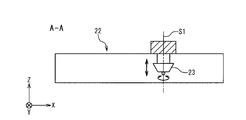
- FIG. 2 is a cross-sectional view of the composite material part manufacturing apparatus of FIG. 1 along AA. It is a side view of the lamination
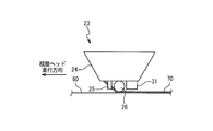
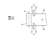
- FIG. 4 is a top view of the lamination roller, camera, and illumination of FIG. 3. It is a side view of the lamination
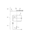
- a cross-sectional view of a part of the tape being affixed (b) an image of that part, and (c) a luminance distribution in the image, in the case where there is no affixed tape near the tape being affixed.
- a cross-sectional view at a site where there is a gap between the tape being pasted and the tape that has been pasted (b) an image of that site, (c) ) Indicates the luminance distribution in the image.
- the inspection data in the case where it is determined that there are gaps in a part where there are a plurality of parts from the part where the tape is pasted to the part where it is pasted and the overlapping is determined in other parts are shown.
- the inspection data in the case where it is determined that all of a plurality of parts from the tape application start part to the application end part are overlapped are shown.
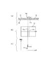
- the composite part manufacturing apparatus 10 manufactures composite parts by executing lamination of fiber reinforced plastic tapes.
- the composite part manufacturing apparatus 10 includes a driving device 22 and a laminated head 23.
- an X axis, a Y axis, and a Z axis that are orthogonal to each other are defined.
- the Z axis is vertically upward.
- the driving device 22 drives the laminated head 23 to translate in parallel to the X axis and parallel to the Y axis.
- the driving device 22 drives the stacking head 23 to translate in parallel with the Z axis, and rotates around the rotation axis S1 parallel to the Z axis.
- the drive device 22 includes three servo mechanisms respectively corresponding to the three translational drives and a servo mechanism corresponding to the rotational drive.
- the stacking head 23 is driven by the driving device 22 and moves relative to the object 60 to be pasted.
- the laminating head 23 affixes the fiber reinforced plastic tape 70 to the object to be affixed 60 while moving.
- the object 60 to be pasted is a mold or a laminated body of fiber reinforced plastic tape laminated on the mold.
- the stacking head 23 includes a tape supply device 24, a cutter 25, and a stacking roller 26. Two photographing units 31 are attached to the stacking head 23.
- the tape supply device 24 sends out the tape 70.
- the stacking roller 26 applies the tape 70 that has been sent out against the object 60 to be applied.
- the lamination roller 26 rotates around the rotation axis S ⁇ b> 2 and presses the tape 70 against the object 60 to be pasted while rolling on the tape 70.
- the rotation axis S2 is perpendicular to the rotation axis S1 and parallel to the width direction of the tape 70.
- the tape 70 includes side end portions 70a and 70b on both sides in the width direction.
- the two imaging units 31 are arranged on the rear side in the moving direction (traveling direction) of the stacking head 23 with respect to the stacking roller 26 so that the pasting state of the tape 70 can be captured.
- the two photographing units 31 are disposed at positions corresponding to the side end portions 70a and 70b, respectively.
- the shooting unit 31 corresponding to the side end portion 70a may be referred to as the left side shooting unit 31, and the shooting unit 31 corresponding to the side end portion 70b may be referred to as the right side shooting unit 31.
- the left photographing unit 31 is disposed right above the side end portion 70a and faces the side end portion 70a, and is disposed at a position shifted from the position directly above the side end portion 70a to the outside in the width direction of the tape 70.
- Illumination 33 that faces the end portion 70a and illumination 33 that is disposed at a position shifted inward in the width direction of the tape 70 from directly above the side end portion 70a and that faces the side end portion 70a.
- the right photographing unit 31 is disposed right above the side end portion 70b and faces the side end portion 70b.
- the right photographing unit 31 is disposed at a position shifted from the position directly above the side end portion 70b to the outside in the width direction of the tape 70.
- the camera 32 is, for example, a CCD (Charge Coupled Device) camera.
- the optical axis of the camera 32 is parallel to the Z axis.
- the illumination 33 is, for example, LED (Light Emitting Diode) illumination.
- the illumination 33 irradiates the fiber reinforced plastic tape with light obliquely, the side end portion of the fiber reinforced plastic tape is emphasized in the image photographed by the photographing unit 31.
- the side end portion 70 a is included in the shooting range of the left shooting unit 31, but is not included in the shooting range of the right shooting unit 31.
- the side end portion 70 b is included in the shooting range of the right shooting unit 31, but is not included in the shooting range of the left shooting unit 31.
- the camera 32 and the illumination 33 are arranged so that the distance between the camera 32 and the tape 70 in the Z-axis direction is larger than the distance between the illumination 33 and the tape in the Z-axis direction.
- the composite part manufacturing apparatus 10 includes an automatic laminating apparatus 20 and an inspection apparatus 30.
- the automatic laminating apparatus 20 includes a control device 21 in addition to the driving device 22 and the laminating head 23 described above.
- the inspection device 30 includes an information processing device 34 as an inspection computer in addition to the two imaging units 31 described above.
- the information processing device 34 includes an input device 35, an output device 36, a processing device 37, and a storage device 38.
- the automatic laminating apparatus 20 executes the lamination of the fiber reinforced plastic tape according to the lamination program (lamination procedure) 27.
- the control device 21 controls the drive device 22, the tape supply device 24, and the cutter 25 based on the lamination program 27 in order to execute the lamination of the fiber reinforced plastic tape.
- the control device 21 controls the driving device 22 so that the rotation axis S ⁇ b> 2 of the stacking roller 26 is perpendicular to the moving direction of the stacking head 23 while the tape 70 is attached. Furthermore, the control device 21 outputs an operation state notification signal for notifying the operation state of the automatic laminating device 20 to the inspection device 30.
- the inspection device 30 determines the application state of the fiber reinforced plastic tape attached by the automatic laminating device 20 based on the image taken by the camera 32, and generates inspection data 40 indicating the determination result.
- the storage device 38 stores inspection data 40.
- the inspection device 30 determines whether or not the fiber-reinforced plastic tape has been properly applied based on the inspection data 40, and outputs an inspection result signal indicating the determination result.
- the automatic laminating apparatus 20 stops or continues the lamination of the fiber reinforced plastic tape based on the inspection result signal.
- the lamination program 27 specifies that the tapes arranged in the same layer of the composite part are affixed in parallel to each other and that the tapes arranged in the same layer do not overlap each other. This point will be specifically described below.
- the laminating program 27 may prescribe that there is no fiber reinforced plastic tape arranged in the same layer as the tape 70 in the photographing range of the left photographing unit 31 as shown in FIG.
- the case where the lamination program 27 prescribes that there is no fiber reinforced plastic tape arranged in the same layer as the tape 70 in the photographing range of the left photographing unit 31 is, for example, that the lamination program 27 is a composite material part.
- the lamination program 27 includes a fiber reinforced plastic tape 71 arranged in the same layer as the tape 70 on the side end portion 70 a side of the tape 70, and the tape 70 of the tape 71. In some cases, a gap having a predetermined size (gap amount) is provided between the side end portion 71b and the side end portion 70a.
- the predetermined gap amount is set to a value such that both the side end portion 70 a and the side end portion 71 b exist in the shooting range of the left shooting unit 31.
- the lamination program 27 includes a fiber reinforced plastic tape 71 arranged in the same layer as the tape 70 on the side end portion 70a side of the tape 70, and the tape 70 and It is not stipulated that 71 overlap each other.
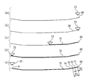
- FIG. 7A a case will be described where sticking is performed so that there is no fiber reinforced plastic tape other than the tape 70 in the photographing range of the left photographing unit 31.
- the image 51 captured by the camera 32 of the left imaging unit 31 does not show any side end other than the side end 70a.
- the W axis of the image 51 is parallel to the width direction of the tape 70.
- FIG. 7C shows the luminance distribution on the W axis of the image 51. The luminance distribution has only a rise (peak) corresponding to the side end portion 70a.
- FIG. 8B shows the side end portions 70a and 71b in the image 52 photographed by the camera 32 of the left photographing unit 31.
- the W axis of the image 52 is parallel to the width direction of the tape 70.
- FIG. 8C shows the luminance distribution on the W axis of the image 52.
- the luminance distribution has a rise corresponding to the side end portion 70a and a rise corresponding to the side end portion 71b.
- FIG. 9A the case where the tape 70 and the tape 71 are pasted so as to overlap in the photographing range of the left photographing unit 31 will be described.
- the side end portion 70a is disposed on the tape 71 and the side end portion 71b is disposed below the tape 70 as shown in FIG. .
- FIG. 9B only the side end portion 70 a is shown in the image 53 taken by the camera 32 of the left side shooting unit 31, and the side end portion 71 b is under the tape 70, so that it is not shown.
- the W axis of the image 53 is parallel to the width direction of the tape 70.
- FIG. 9C shows the luminance distribution on the W axis of the image 53. The luminance distribution has only a rise corresponding to the side end portion 70a.
- the processing device 37 when the rise of the brightness detected from the image is one as shown in FIGS. 7C and 9C, the tape 70 is connected to the other tape at the portion where the image is captured. Judged as overlapping. As shown in FIG. 8C, the processing device 37, when there are two rises in luminance detected from the image, is located between the tape 70 and the tape adjacent to the tape 70 at the site where the image is captured. It is determined that a gap is provided, and the gap amount is calculated based on the distance P between the two rising edges. Here, it is possible to detect the rise of luminance by applying a known edge detection method.
- the automatic laminating apparatus 20 executes the lamination of the fiber reinforced plastic tape according to the lamination program 27.
- FIG. 10A shows a stacking preparation state during execution of the stacking. At this time, the stacking head 23 is disposed at a position away from the object to be pasted 60.
- the control device 21 causes the driving device 22 to move the stacking head 23 in the Z-axis direction, and sandwiches the start portion of the tape 70 between the stacking roller 26 and the object 60 to be pasted.
- FIG. 10B shows this state.
- the automatic laminating device 20 starts pasting the tape 70.
- the control device 10 drives the drive device 22 by numerical control so that the stacking head 23 moves along the path specified by the stacking program 27.
- the tape supply device 24 sends out the tape 70, and the laminating roller 26 presses the affixed tape 70 against the object 60 to be affixed.
- the control device 21 outputs operation state signals indicating the X, Y, and Z coordinates of the laminated head 23 at regular time intervals.
- FIG. 10C shows a state where the tape 70 is being attached.
- FIG. 10D shows a state in which the stacking head 23 has stopped at the attachment end position.
- the control device 21 causes the driving device 22 to move the stacking head 23 in the Z-axis direction and hold the stacking head 23 at a standby position away from the object 60 to be pasted.
- FIG. 10E shows a state in which the laminated head 23 is held at the standby position.
- the control device 21 waits for an inspection result signal from the inspection device 30 in a state where the laminated head 23 is held at the standby position.
- the operation of the inspection apparatus 30 while the tape 70 is being applied will be described.
- the camera 32 starts photographing at a predetermined time interval in response to the pasting start signal, and finishes photographing in response to the pasting end signal. Accordingly, the camera 32 captures a plurality of images by capturing images of the plurality of portions V1 to Vn from the start portion V1 to the end portion Vn of the tape 70.
- the processing device 37 calculates the distance D between each part of the plurality of parts and the sticking start part V1 based on the operation state signal indicating the X, Y, and Z coordinates of the stacking head 23.
- the processing device 37 detects the brightness rise from each image of the plurality of images for the plurality of portions V1 to Vn, and the tape 70 overlaps with other tapes based on the number of brightness rises detected from each image, or It is determined whether there is a gap between the tape 70 and another tape.
- the processing device 37 determines that the tape 70 and another tape are overlapped when the number of luminance rises is 1, and if there is a gap between the tape 70 and another tape when the number of luminance rises is 2. judge. When the number of luminance rises is 2 (when it is determined that there is a gap), the processing device 37 calculates the gap amount G between the tape 70 and another tape based on the distance between the luminance rises.
- the processing device 37 generates inspection data 40 and stores it in the storage device 38.
- the inspection data 40 is determined to be a distance D from the attachment start site V1, an overlap or gap determination result, and a gap for all of the plurality of sites V1 to Vn from the application start site V1 to the application end site Vn of the tape 70.
- the gap amount G is shown.
- the processing device 37 determines whether or not the tape 70 has been properly applied based on the inspection data 40, and outputs an inspection result signal indicating the determination result.
- FIG. 11 shows the inspection data 40 when it is determined that there are gaps in all of the plurality of parts V1 to Vn from the start part V1 to the end part Vn of the tape 70.
- the inspection data 40 indicates that there are gaps (GAP) and the gap amounts are G1 to Gn in the plurality of parts V1 to Vn whose distances from the sticking start part V1 are D1 to Dn.
- GAP gaps
- a part having a distance Dn from the sticking start part V1 is a sticking end part Vn.
- the processing device 37 sets each of the gap amounts G1 to Gn to a predetermined amount. Compare with the threshold value. When all of the gap amounts G1 to Gn are smaller than the predetermined threshold value, the processing device 37 determines that the tape 70 has been properly attached and outputs a stacking continuation signal as an inspection result signal. When at least one of the gap amounts G1 to Gn is larger than the predetermined threshold value, the processing device 37 determines that the tape 70 has not been properly applied and outputs a stacking stop signal as an inspection result signal.
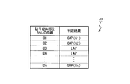
- FIG. 12 shows that the distance from the application start site V1 among the plurality of sites V1 to Vn from the application start site V1 to the application end site Vn of the tape 70 is a gap at the sites V1, V2, and Vn of D1, D2, and Dn.
- the inspection data 40 is shown when the distance from the sticking start site V1 among the plurality of sites V1 to Vn is determined to be overlap (LAP) at the sites V3 and V4 of D3 and D4.
- LAP overlap
- FIG. 13 shows the inspection data 40 in the case where it is determined that all of a plurality of parts from the start part to the end part of the tape 70 are overlapped.
- the laminating program 27 stipulates that the tapes arranged in the same layer of the composite part do not overlap with each other, and therefore, a plurality of parts V1 to Vn from the sticking start part V1 to the sticking end part Vn. In all of the cases, the possibility that the tape 70 overlaps with other tapes is very low. Accordingly, as shown in FIG. 13, when it is determined that all of a plurality of portions are overlapped, the lamination program 27 specifies that the fiber reinforced plastic tape arranged in the same layer as the tape 70 does not exist in the shooting range of the camera 32. It is thought that.
- the processing device 37 when it is determined that all of the plurality of parts V1 to Vn from the sticking start part V1 to the sticking end part Vn of the tape 70 are overlapped, the processing device 37 appropriately executes the sticking of the tape 70.
- the stacking continuation signal is output as the inspection result signal.
- the automatic laminating apparatus 20 continues the lamination of the fiber reinforced plastic tape based on the lamination continuation signal.
- the control device 21 moves the lamination head 23 from the standby position in order to apply the next tape based on the lamination continuation signal.
- the automatic laminating apparatus 20 stops the lamination of the fiber reinforced plastic tape based on the lamination stop signal. In this case, it is necessary for the operator to visually determine the affixing state of the tape 70, and when it is necessary to redo the affixing, the operator operates the automatic lamination apparatus 20 to redo the affixing, and the affixing of the affixing is required. If not, the automatic laminating apparatus 20 is operated to apply the next tape.
- the tape 70 properly attached according to the stacking program 27 is incorrectly attached. It is possible to prevent the lamination from being stopped although it is not necessary to determine that it is appropriate.
- the following method can be used in place of the method in which the inspection apparatus 30 described above automatically outputs a stacking continuation signal or a stacking stop signal based on the inspection data 40.
- the output device 36 outputs the result data 40.
- the operator determines whether or not the tape 70 has been properly applied based on the output result data 40 and operates the input device 35 to cause the inspection device 30 to output a stacking continuation signal or a stacking stop signal. .
- the composite material part manufacturing method, the composite material part manufacturing apparatus, and the inspection apparatus of the present invention can prevent erroneously determining that the fiber reinforced plastic tape that has been properly applied is inadequate.
Abstract
Disclosed is a method for producing composite material components, which involves a process for laminating a fiber-reinforced plastic tape. Said method also involves determining, while a fiber-reinforced plastic tape is being laminated, the attachment state of a first fiber-reinforced plastic tape throughout a plurality of sections from the section in which the attachment of the first fiber-reinforced plastic tape begins to the section in which the attachment of said tape ends, wherein the aforementioned lamination process stops when it is determined that the first fiber-reinforced plastic tape overlaps with a second fiber-reinforced plastic tape in a first section among the aforementioned plurality of sections, and also when it is determined that there is a gap between the first fiber-reinforced plastic tape and the second fiber-reinforced plastic tape in a second section among the aforementioned plurality of sections, and the aforementioned lamination process continues when it is determined that the first fiber-reinforced plastic tape and the second fiber-reinforced plastic tape overlap on the entirety of the aforementioned plurality of sections.
Description
本発明は、繊維強化プラスチック部材を用いた複合材部品の製造に関する。
本願は、2009年11月18日に、日本に出願された特願2009-263293号に基づき優先権を主張し、その内容をここに援用する。 The present invention relates to the manufacture of composite parts using fiber reinforced plastic members.
This application claims priority based on Japanese Patent Application No. 2009-263293 filed in Japan on November 18, 2009, the contents of which are incorporated herein by reference.
繊維強化プラスチック部材は、航空機の構造部材等として用いられている。特許文献1は、ファイバプレスメント(Fiber Placement)法により繊維強化プラスチックテープの積層成形を自動的に実行する自動積層成形装置を開示している。特許文献1は、繊維強化プラスチックテープの貼り付け状態の判定について開示していない。
Fiber reinforced plastic members are used as aircraft structural members. Patent Document 1 discloses an automatic lamination molding apparatus that automatically executes lamination molding of a fiber reinforced plastic tape by a fiber placement method. Patent Document 1 does not disclose the determination of the application state of the fiber reinforced plastic tape.
特許文献2は、エッジ検出に基づくパターン検査方法を開示している。
Patent Document 2 discloses a pattern inspection method based on edge detection.
本発明の複合材部品製造方法、複合材部品製造装置及び検査装置により、適切に貼り付けられた繊維強化プラスチックテープの貼り付け状態を誤って不適切と判定することが防止される。
The composite material part manufacturing method, the composite material part manufacturing apparatus, and the inspection apparatus of the present invention can prevent erroneously determining that the fiber reinforced plastic tape that has been properly applied is inadequate.
本発明は、実施形態に示す各図に対応付けした以下の構成を採用している。ただし、各要素に付した符号はその要素の例示に過ぎず、各要素を限定するものではない。
The present invention adopts the following configuration corresponding to each diagram shown in the embodiment. However, the code | symbol attached | subjected to each element is only the illustration of the element, and does not limit each element.
本発明による複合材部品製造方法は、繊維強化プラスチックテープを積層する過程を有する。複合材部品製造方法は、繊維強化プラスチックテープの積層中に、第1繊維強化プラスチックテープ(70)の貼り始め部位(V1)から貼り終り部位(Vn)までの複数部位(V1~Vn)において前記第1繊維強化プラスチックテープの貼り付け状態を判定すること、を含む。前記複数部位の第1部位(V3、V4)において前記第1繊維強化プラスチックテープが第2繊維強化プラスチックテープと重なっていると判定され、且つ、前記複数部位の第2部位(V1、V2、Vn)において前記第1繊維強化プラスチックテープと前記第2繊維強化プラスチックテープとの間に隙間があると判定された場合に前記積層が停止される。前記複数部位の全てにおいて前記第1繊維強化プラスチックテープが前記第2繊維強化プラスチックテープと重なっていると判定された場合に前記積層が継続される。
The composite part manufacturing method according to the present invention includes a process of laminating fiber reinforced plastic tape. In the composite part manufacturing method, during the lamination of the fiber reinforced plastic tape, the first fiber reinforced plastic tape (70) is laminated at a plurality of sites (V1 to Vn) from the start site (V1) to the end site (Vn). Determining the application state of the first fiber-reinforced plastic tape. It is determined that the first fiber reinforced plastic tape is overlapped with the second fiber reinforced plastic tape in the plurality of first portions (V3, V4), and the plurality of second portions (V1, V2, Vn). ), The lamination is stopped when it is determined that there is a gap between the first fiber reinforced plastic tape and the second fiber reinforced plastic tape. The lamination is continued when it is determined that the first fiber reinforced plastic tape overlaps the second fiber reinforced plastic tape in all of the plurality of portions.
前記貼り付け状態を判定することは、移動しながら前記第1繊維強化プラスチックテープを貼り付ける積層ヘッド(23)に取り付けられたカメラ(32)が前記複数部位それぞれの画像を撮影することで複数画像を撮影すること、前記複数部位について、前記複数画像の各画像から検出される輝度立ち上がりの数に基づいて前記第1繊維強化プラスチックテープが前記第2繊維強化プラスチックテープと重なっているか又は前記第1繊維強化プラスチックテープと前記第2繊維強化プラスチックテープの間に隙間があるかを判定すること、を含んでいてもよい。
Determining the pasting state means that the camera (32) attached to the laminated head (23) to which the first fiber reinforced plastic tape is stuck while moving takes images of the plurality of portions. The first fiber reinforced plastic tape overlaps the second fiber reinforced plastic tape based on the number of luminance rises detected from each of the plurality of images for the plurality of sites or the first Determining whether there is a gap between the fiber reinforced plastic tape and the second fiber reinforced plastic tape.
前記貼り付け状態を判定することは、前記輝度立ち上がりの数が2の場合に前記輝度立ち上がり間の距離に基づいて前記第1繊維強化プラスチックテープと前記第2繊維強化プラスチックテープの間の隙間量を算出すること、を含んでいてもよい。
Determining the pasting state means that the gap amount between the first fiber reinforced plastic tape and the second fiber reinforced plastic tape is determined based on the distance between the luminance rises when the number of the luminance rises is two. Calculating.
前記複数部位の全てにおいて前記第1繊維強化プラスチックテープと前記第2繊維強化プラスチックテープとの間に隙間があると判定された場合で、前記複数部位の少なくとも一つにおいて前記第1繊維強化プラスチックテープと前記第2繊維強化プラスチックテープとの間の隙間量が所定の閾値より大きい場合に前記積層が停止されてもよい。
When it is determined that there is a gap between the first fiber reinforced plastic tape and the second fiber reinforced plastic tape in all of the plurality of parts, the first fiber reinforced plastic tape is used in at least one of the plurality of parts. The stacking may be stopped when a gap amount between the second fiber reinforced plastic tape and the second fiber reinforced plastic tape is larger than a predetermined threshold.
前記積層は、同一層に配置される繊維強化プラスチックテープどうしが重ならないことを規定した積層プログラム(27)に従って実行されてもよい。
The lamination may be executed according to a lamination program (27) that specifies that fiber reinforced plastic tapes arranged in the same layer do not overlap.
本発明による複合材部品製造装置(10)は、繊維強化プラスチックテープの積層を実行する自動積層装置(20)と、前記自動積層装置が前記積層において貼り付けた第1繊維強化プラスチックテープ(70)の貼り始め部位(V1)から貼り終り部位(Vn)までの複数部位(V1~Vn)において前記第1繊維強化プラスチックテープの貼り付け状態を判定する検査装置(30)と、を具備する。前記自動積層装置は、前記検査装置が前記複数部位の第1部位(V3、V4)において前記第1繊維強化プラスチックテープが第2繊維強化プラスチックテープと重なっていると判定し、且つ、前記複数部位の第2部位(V1、V2、Vn)において前記第1繊維強化プラスチックテープと前記第2繊維強化プラスチックテープとの間に隙間があると判定した場合に、前記積層を停止する。前記自動積層装置は、前記検査装置が前記複数部位の全てにおいて前記第1繊維強化プラスチックテープが前記第2繊維強化プラスチックテープと重なっていると判定した場合に、前記積層を継続する。
The composite part manufacturing apparatus (10) according to the present invention includes an automatic laminating apparatus (20) for laminating fiber reinforced plastic tape, and a first fiber reinforced plastic tape (70) attached by the automatic laminating apparatus in the laminating. And an inspection device (30) for determining the application state of the first fiber-reinforced plastic tape at a plurality of sites (V1 to Vn) from the application start site (V1) to the application end site (Vn). In the automatic laminating apparatus, the inspection apparatus determines that the first fiber reinforced plastic tape overlaps the second fiber reinforced plastic tape in the first part (V3, V4) of the plurality of parts, and the plurality of parts When it is determined that there is a gap between the first fiber reinforced plastic tape and the second fiber reinforced plastic tape at the second portion (V1, V2, Vn), the lamination is stopped. The automatic laminating apparatus continues the laminating when the inspection apparatus determines that the first fiber reinforced plastic tape overlaps the second fiber reinforced plastic tape in all of the plurality of portions.
前記自動積層装置は、移動しながら前記第1繊維強化プラスチックテープを貼り付ける積層ヘッド(23)を備えていてもよい。前記検査装置は、前記積層ヘッドに取り付けられたカメラ(32)を備えていてもよい。前記カメラは、前記複数部位ぞれぞれの画像を撮影することで複数画像を撮影する。前記検査装置は、前記複数部位について、前記複数画像の各画像から検出される輝度立ち上がりの数に基づいて前記第1繊維強化プラスチックテープが前記第2繊維強化プラスチックテープと重なっているか又は前記第1繊維強化プラスチックテープと前記第2繊維強化プラスチックテープの間に隙間があるかを判定してもよい。
The automatic laminating apparatus may include a laminating head (23) for affixing the first fiber reinforced plastic tape while moving. The inspection apparatus may include a camera (32) attached to the laminated head. The camera captures a plurality of images by capturing images of the plurality of parts. In the inspection apparatus, the first fiber reinforced plastic tape overlaps the second fiber reinforced plastic tape or the first fiber based on the number of luminance rises detected from each image of the plurality of images. It may be determined whether there is a gap between the fiber reinforced plastic tape and the second fiber reinforced plastic tape.
前記検査装置は、前記輝度立ち上がりの数が2の場合に前記輝度立ち上がり間の距離に基づいて前記第1繊維強化プラスチックテープと前記第2繊維強化プラスチックテープの間の隙間量を算出してもよい。
The inspection device may calculate a gap amount between the first fiber reinforced plastic tape and the second fiber reinforced plastic tape based on a distance between the luminance rises when the number of luminance rises is two. .
前記自動積層装置は、前記複数部位の全てにおいて前記第1繊維強化プラスチックテープと前記第2繊維強化プラスチックテープとの間に隙間があると判定された場合で、前記複数部位の少なくとも一つにおいて前記第1繊維強化プラスチックテープと前記第2繊維強化プラスチックテープとの間の隙間量が所定の閾値より大きい場合に、前記積層を停止してもよい。
In the automatic laminating apparatus, when it is determined that there is a gap between the first fiber reinforced plastic tape and the second fiber reinforced plastic tape in all of the plurality of parts, The lamination may be stopped when a gap amount between the first fiber reinforced plastic tape and the second fiber reinforced plastic tape is larger than a predetermined threshold.
前記自動積層装置は、同一層に配置される繊維強化プラスチックテープどうしが重ならないことを規定した積層プログラム(27)に従って前記積層を実行してもよい。
The automatic laminating apparatus may execute the laminating according to a laminating program (27) that stipulates that fiber reinforced plastic tapes arranged in the same layer do not overlap.
前記検査装置は、照明(33)を備えていてもよい。前記カメラは、前記第1繊維強化プラスチックテープの側端部の真上に配置され且つ前記側端部を向くように前記積層ヘッドに取り付けられていてもよい。前記照明は、前記側端部の真上から前記第1繊維強化プラスチックテープの幅方向にずれた位置に配置され且つ前記側端部を向くように前記積層ヘッドに取り付けられていてもよい。
The inspection apparatus may include an illumination (33). The camera may be attached to the lamination head so as to be disposed immediately above a side end portion of the first fiber reinforced plastic tape and to face the side end portion. The illumination may be arranged at a position shifted in the width direction of the first fiber-reinforced plastic tape from directly above the side end portion and attached to the laminated head so as to face the side end portion.
本発明による検査装置(30)は、繊維強化プラスチックテープの積層を実行する自動積層装置(20)の積層ヘッド(23)に取り付けられたカメラ(32)と、情報処理装置(34)と、を具備する。前記積層ヘッドは、前記積層において移動しながら第1繊維強化プラスチックテープ(70)を貼り付ける。前記情報処理装置は、前記カメラが撮影した複数画像に基づいて前記第1繊維強化プラスチックの複数部位(V1~Vn)における前記第1繊維強化プラスチックテープの貼り付け状態を判定し、前記貼り付け状態の判定結果に基づいて積層停止信号又は積層継続信号を出力する。
An inspection apparatus (30) according to the present invention includes a camera (32) attached to a lamination head (23) of an automatic lamination apparatus (20) that performs lamination of fiber reinforced plastic tape, and an information processing apparatus (34). It has. The lamination head applies the first fiber-reinforced plastic tape (70) while moving in the lamination. The information processing apparatus determines an application state of the first fiber reinforced plastic tape at a plurality of parts (V1 to Vn) of the first fiber reinforced plastic based on a plurality of images taken by the camera, and the application state Based on the determination result, a stacking stop signal or a stacking continuation signal is output.
前記情報処理装置は、前記複数部位の第1部位(V3、V4)において前記第1繊維強化プラスチックテープが第2繊維強化プラスチックテープと重なっていると判定し、且つ、前記複数部位の第2部位(V1、V2、Vn)において前記第1繊維強化プラスチックテープと前記第2繊維強化プラスチックテープとの間に隙間があると判定した場合に、前記積層停止信号を出力してもよい、前記複数部位の全てにおいて前記第1繊維強化プラスチックテープが前記第2繊維強化プラスチックテープと重なっていると判定した場合に、前記積層継続信号を出力してもよい。
The information processing apparatus determines that the first fiber reinforced plastic tape overlaps the second fiber reinforced plastic tape in the first part (V3, V4) of the plurality of parts, and the second part of the plurality of parts. The plurality of portions that may output the stacking stop signal when it is determined that there is a gap between the first fiber reinforced plastic tape and the second fiber reinforced plastic tape in (V1, V2, Vn) In all of the above, when it is determined that the first fiber reinforced plastic tape overlaps the second fiber reinforced plastic tape, the lamination continuation signal may be output.
本発明の複合材部品製造方法、複合材部品製造装置及び検査装置によれば、適切に貼り付けられた繊維強化プラスチックテープの貼り付け状態を誤って不適切と判定することが防止される。
According to the composite part manufacturing method, the composite part manufacturing apparatus, and the inspection apparatus of the present invention, it is possible to prevent erroneously determining that the appropriately attached fiber reinforced plastic tape is inadequate.
添付図面を参照して、本発明による複合材部品製造方法、複合材部品製造装置及び検査装置を実施するための形態を以下に説明する。
With reference to the accompanying drawings, embodiments for carrying out a composite material part manufacturing method, a composite material part manufacturing apparatus and an inspection apparatus according to the present invention will be described below.
(第1の実施形態)
図1を参照して、本発明の第1の実施形態に係る複合材部品製造装置10を説明する。複合材部品製造装置10は、繊維強化プラスチックテープの積層を実行して複合材部品を製造する。複合材部品製造装置10は、駆動装置22と、積層ヘッド23を備える。複合材部品製造装置10について、互いに直交するX軸、Y軸、Z軸が定義されている。Z軸は、鉛直上向きである。駆動装置22は、積層ヘッド23をX軸に平行及びY軸に平行に並進駆動する。 (First embodiment)
With reference to FIG. 1, the composite materialcomponent manufacturing apparatus 10 which concerns on the 1st Embodiment of this invention is demonstrated. The composite part manufacturing apparatus 10 manufactures composite parts by executing lamination of fiber reinforced plastic tapes. The composite part manufacturing apparatus 10 includes a driving device 22 and a laminated head 23. For the composite material part manufacturing apparatus 10, an X axis, a Y axis, and a Z axis that are orthogonal to each other are defined. The Z axis is vertically upward. The driving device 22 drives the laminated head 23 to translate in parallel to the X axis and parallel to the Y axis.
図1を参照して、本発明の第1の実施形態に係る複合材部品製造装置10を説明する。複合材部品製造装置10は、繊維強化プラスチックテープの積層を実行して複合材部品を製造する。複合材部品製造装置10は、駆動装置22と、積層ヘッド23を備える。複合材部品製造装置10について、互いに直交するX軸、Y軸、Z軸が定義されている。Z軸は、鉛直上向きである。駆動装置22は、積層ヘッド23をX軸に平行及びY軸に平行に並進駆動する。 (First embodiment)
With reference to FIG. 1, the composite material
図2において、駆動装置22は、積層ヘッド23をZ軸に平行に並進駆動し、Z軸に平行な回転軸S1まわりに回転駆動する。駆動装置22は、上記三つの並進駆動にそれぞれ対応する三つのサーボ機構と、上記回転駆動に対応するサーボ機構を備える。
2, the driving device 22 drives the stacking head 23 to translate in parallel with the Z axis, and rotates around the rotation axis S1 parallel to the Z axis. The drive device 22 includes three servo mechanisms respectively corresponding to the three translational drives and a servo mechanism corresponding to the rotational drive.
図3において、積層ヘッド23は、駆動装置22によって駆動されて貼り付け対象物体60に対して移動する。積層ヘッド23は、移動しながら繊維強化プラスチックテープ70を貼り付け対象物体60に貼り付ける。ここで、貼り付け対象物体60は、型又は型の上に積層された繊維強化プラスチックテープの積層体である。積層ヘッド23は、テープ供給装置24と、カッター25と、積層ローラー26を備える。積層ヘッド23には、二つの撮影ユニット31が取り付けられている。テープ供給装置24は、テープ70を送り出す。積層ローラー26は、送り出されたテープ70を貼り付け対象物体60に押し付けて貼り付ける。
3, the stacking head 23 is driven by the driving device 22 and moves relative to the object 60 to be pasted. The laminating head 23 affixes the fiber reinforced plastic tape 70 to the object to be affixed 60 while moving. Here, the object 60 to be pasted is a mold or a laminated body of fiber reinforced plastic tape laminated on the mold. The stacking head 23 includes a tape supply device 24, a cutter 25, and a stacking roller 26. Two photographing units 31 are attached to the stacking head 23. The tape supply device 24 sends out the tape 70. The stacking roller 26 applies the tape 70 that has been sent out against the object 60 to be applied.
図4において、積層ローラー26は、回転軸S2まわりに回転してテープ70上を転がりながらテープ70を貼り付け対象物体60に押し付ける。回転軸S2は、回転軸S1に垂直であり、テープ70の幅方向に平行である。テープ70は、幅方向の両側にそれぞれ側端部70a及び70bを備える。二つの撮影ユニット31は、テープ70の貼り付け状態を撮影可能なように、積層ローラー26に対して積層ヘッド23の移動方向(進行方向)後方側に配置される。二つの撮影ユニット31は、それぞれ側端部70a及び70bに対応する位置に配置される。以下、側端部70aに対応する撮影ユニット31を左側撮影ユニット31と呼ぶ場合があり、側端部70bに対応する撮影ユニット31を右側撮影ユニット31と呼ぶ場合がある。左側撮影ユニット31は、側端部70aの真上に配置され且つ側端部70aを向くカメラ32と、側端部70aの真上からテープ70の幅方向外側にずれた位置に配置され且つ側端部70aを向く照明33と、側端部70aの真上からテープ70の幅方向内側にずれた位置に配置され且つ側端部70aを向く照明33とを備える。右側撮影ユニット31は、側端部70bの真上に配置され且つ側端部70bを向くカメラ32と、側端部70bの真上からテープ70の幅方向外側にずれた位置に配置され且つ側端部70bを向く照明33と、側端部70bの真上からテープ70の幅方向内側にずれた位置に配置され且つ側端部70aを向く照明33とを備える。つまり、照明33は、側端部70a又は70bの真上から回転軸S2に平行な直線に沿ってずれた位置に配置される。カメラ32は、例えば、CCD(Charge Coupled Device)カメラである。カメラ32の光軸はZ軸に平行である。照明33は、例えば、LED(Light Emitting Diode)照明である。
4, the lamination roller 26 rotates around the rotation axis S <b> 2 and presses the tape 70 against the object 60 to be pasted while rolling on the tape 70. The rotation axis S2 is perpendicular to the rotation axis S1 and parallel to the width direction of the tape 70. The tape 70 includes side end portions 70a and 70b on both sides in the width direction. The two imaging units 31 are arranged on the rear side in the moving direction (traveling direction) of the stacking head 23 with respect to the stacking roller 26 so that the pasting state of the tape 70 can be captured. The two photographing units 31 are disposed at positions corresponding to the side end portions 70a and 70b, respectively. Hereinafter, the shooting unit 31 corresponding to the side end portion 70a may be referred to as the left side shooting unit 31, and the shooting unit 31 corresponding to the side end portion 70b may be referred to as the right side shooting unit 31. The left photographing unit 31 is disposed right above the side end portion 70a and faces the side end portion 70a, and is disposed at a position shifted from the position directly above the side end portion 70a to the outside in the width direction of the tape 70. Illumination 33 that faces the end portion 70a and illumination 33 that is disposed at a position shifted inward in the width direction of the tape 70 from directly above the side end portion 70a and that faces the side end portion 70a. The right photographing unit 31 is disposed right above the side end portion 70b and faces the side end portion 70b. The right photographing unit 31 is disposed at a position shifted from the position directly above the side end portion 70b to the outside in the width direction of the tape 70. Illumination 33 that faces the end portion 70b and illumination 33 that is disposed at a position shifted inward in the width direction of the tape 70 from directly above the side end portion 70b and that faces the side end portion 70a. That is, the illumination 33 is arranged at a position shifted from a position directly above the side end portion 70a or 70b along a straight line parallel to the rotation axis S2. The camera 32 is, for example, a CCD (Charge Coupled Device) camera. The optical axis of the camera 32 is parallel to the Z axis. The illumination 33 is, for example, LED (Light Emitting Diode) illumination.
上述のように照明33が繊維強化プラスチックテープに斜めに光を照射するため、撮影ユニット31が撮影した画像において繊維強化プラスチックテープの側端部が強調される。
As described above, since the illumination 33 irradiates the fiber reinforced plastic tape with light obliquely, the side end portion of the fiber reinforced plastic tape is emphasized in the image photographed by the photographing unit 31.
なお、側端部70aは、左側撮影ユニット31の撮影範囲に含まれるが、右側撮影ユニット31の撮影範囲に含まれない。側端部70bは、右側撮影ユニット31の撮影範囲に含まれるが、左側撮影ユニット31の撮影範囲に含まれない。
The side end portion 70 a is included in the shooting range of the left shooting unit 31, but is not included in the shooting range of the right shooting unit 31. The side end portion 70 b is included in the shooting range of the right shooting unit 31, but is not included in the shooting range of the left shooting unit 31.
図5において、カメラ32とテープ70のZ軸方向距離が照明33とテープのZ軸方向距離より大きくなるように、カメラ32及び照明33が配置される。
5, the camera 32 and the illumination 33 are arranged so that the distance between the camera 32 and the tape 70 in the Z-axis direction is larger than the distance between the illumination 33 and the tape in the Z-axis direction.
図6において、複合材部品製造装置10は、自動積層装置20と、検査装置30を備える。自動積層装置20は、既述の駆動装置22及び積層ヘッド23に加えて、制御装置21を備える。検査装置30は、既述の二つの撮影ユニット31に加えて、検査用コンピュータとしての情報処理装置34を備える。情報処理装置34は、入力装置35と、出力装置36と、処理装置37と、記憶装置38を備える。
6, the composite part manufacturing apparatus 10 includes an automatic laminating apparatus 20 and an inspection apparatus 30. The automatic laminating apparatus 20 includes a control device 21 in addition to the driving device 22 and the laminating head 23 described above. The inspection device 30 includes an information processing device 34 as an inspection computer in addition to the two imaging units 31 described above. The information processing device 34 includes an input device 35, an output device 36, a processing device 37, and a storage device 38.
自動積層装置20は、積層プログラム(積層手順)27に従って繊維強化プラスチックテープの積層を実行する。制御装置21は、繊維強化プラスチックテープの積層の実行のため、積層プログラム27に基づいて駆動装置22、テープ供給装置24、及びカッター25を制御する。制御装置21は、テープ70の貼り付け中に積層ローラー26の回転軸S2が積層ヘッド23の移動方向に垂直になるように駆動装置22を制御する。更に、制御装置21は、自動積層装置20の動作状態を通知するための動作状態通知信号を検査装置30に出力する。
The automatic laminating apparatus 20 executes the lamination of the fiber reinforced plastic tape according to the lamination program (lamination procedure) 27. The control device 21 controls the drive device 22, the tape supply device 24, and the cutter 25 based on the lamination program 27 in order to execute the lamination of the fiber reinforced plastic tape. The control device 21 controls the driving device 22 so that the rotation axis S <b> 2 of the stacking roller 26 is perpendicular to the moving direction of the stacking head 23 while the tape 70 is attached. Furthermore, the control device 21 outputs an operation state notification signal for notifying the operation state of the automatic laminating device 20 to the inspection device 30.
検査装置30は、カメラ32が撮影した画像に基づいて自動積層装置20が貼り付けた繊維強化プラスチックテープの貼り付け状態を判定し、判定結果を示す検査データ40を生成する。記憶装置38は検査データ40を記憶する。検査装置30は、検査データ40に基づいて繊維強化プラスチックテープの貼り付けが適切に行われたか否かを判定し、判定結果を示す検査結果信号を出力する。
The inspection device 30 determines the application state of the fiber reinforced plastic tape attached by the automatic laminating device 20 based on the image taken by the camera 32, and generates inspection data 40 indicating the determination result. The storage device 38 stores inspection data 40. The inspection device 30 determines whether or not the fiber-reinforced plastic tape has been properly applied based on the inspection data 40, and outputs an inspection result signal indicating the determination result.
自動積層装置20は、検査結果信号に基づいて、繊維強化プラスチックテープの積層を停止又は継続する。
The automatic laminating apparatus 20 stops or continues the lamination of the fiber reinforced plastic tape based on the inspection result signal.
ここで、積層プログラム27は、複合材部品の同一層に配置されるテープが互いに平行に貼り付けられること、及び、同一層に配置されるテープどうしが重ならないことを規定する。以下、この点を具体的に説明する。積層プログラム27は、図7(a)に示すように、左側撮影ユニット31の撮影範囲にテープ70と同じ層に配置される繊維強化プラスチックテープが存在しないことを規定する場合がある。ここで、積層プログラム27が左側撮影ユニット31の撮影範囲にテープ70と同じ層に配置される繊維強化プラスチックテープが存在しないことを規定する場合とは、例えば、積層プログラム27が、複合材部品のある層に配置される全ての繊維強化プラスチックテープの中でテープ70が一番はじに位置し、且つ、他のテープがすべてテープ70の側端部70b側に位置するように、ある層に配置される全ての繊維強化プラスチックテープを貼り付けることを自動積層装置20に対して指示している場合である。積層プログラム27は、図8(a)に示すように、テープ70の側端部70aの側にテープ70と同じ層に配置される繊維強化プラスチックテープ71が存在し、且つ、テープ71のテープ70側の側端部71bと側端部70aとの間に所定の大きさ(隙間量)の隙間が設けられることを規定する場合がある。この場合の所定の隙間量は、側端部70a及び側端部71bの両方が左側撮影ユニット31の撮影範囲に存在するような値に設定される。しかし、積層プログラム27は、図9(a)に示すように、テープ70の側端部70aの側にテープ70と同じ層に配置される繊維強化プラスチックテープ71が存在し、且つ、テープ70及び71が互いに重なることを規定しない。
Here, the lamination program 27 specifies that the tapes arranged in the same layer of the composite part are affixed in parallel to each other and that the tapes arranged in the same layer do not overlap each other. This point will be specifically described below. The laminating program 27 may prescribe that there is no fiber reinforced plastic tape arranged in the same layer as the tape 70 in the photographing range of the left photographing unit 31 as shown in FIG. Here, the case where the lamination program 27 prescribes that there is no fiber reinforced plastic tape arranged in the same layer as the tape 70 in the photographing range of the left photographing unit 31 is, for example, that the lamination program 27 is a composite material part. Arranged in a certain layer so that the tape 70 is located first in all the fiber reinforced plastic tapes arranged in a certain layer and all the other tapes are located on the side end portion 70b side of the tape 70. This is a case where the automatic laminating apparatus 20 is instructed to affix all the fiber reinforced plastic tapes. As shown in FIG. 8A, the lamination program 27 includes a fiber reinforced plastic tape 71 arranged in the same layer as the tape 70 on the side end portion 70 a side of the tape 70, and the tape 70 of the tape 71. In some cases, a gap having a predetermined size (gap amount) is provided between the side end portion 71b and the side end portion 70a. In this case, the predetermined gap amount is set to a value such that both the side end portion 70 a and the side end portion 71 b exist in the shooting range of the left shooting unit 31. However, as shown in FIG. 9A, the lamination program 27 includes a fiber reinforced plastic tape 71 arranged in the same layer as the tape 70 on the side end portion 70a side of the tape 70, and the tape 70 and It is not stipulated that 71 overlap each other.
図7(a)に示すように左側撮影ユニット31の撮影範囲にテープ70以外の繊維強化プラスチックテープが存在しないように貼り付けが実行された場合について説明する。図7(b)に示すように、左側撮影ユニット31のカメラ32が撮影した画像51には、側端部70a以外の側端部は写らない。画像51のW軸は、テープ70の幅方向に平行である。図7(c)は、画像51のW軸上の輝度分布を示している。輝度分布は、側端部70aに対応する立ち上がり(ピーク)のみを有する。
As shown in FIG. 7A, a case will be described where sticking is performed so that there is no fiber reinforced plastic tape other than the tape 70 in the photographing range of the left photographing unit 31. As shown in FIG. 7B, the image 51 captured by the camera 32 of the left imaging unit 31 does not show any side end other than the side end 70a. The W axis of the image 51 is parallel to the width direction of the tape 70. FIG. 7C shows the luminance distribution on the W axis of the image 51. The luminance distribution has only a rise (peak) corresponding to the side end portion 70a.
図8(a)に示すように左側撮影ユニット31の撮影範囲にテープ70及びテープ71が存在し、テープ70及びテープ71の間に隙間が設けられるように貼り付けが実行された場合について説明する。図8(b)に示すように、左側撮影ユニット31のカメラ32が撮影した画像52には、側端部70a及び71bが写る。画像52のW軸は、テープ70の幅方向に平行である。図8(c)は、画像52のW軸上の輝度分布を示している。輝度分布は、側端部70aに対応する立ち上がりと側端部71bに対応する立ち上がりとを有する。
A case where the tape 70 and the tape 71 exist in the photographing range of the left photographing unit 31 as shown in FIG. 8A and the pasting is performed so that a gap is provided between the tape 70 and the tape 71 will be described. . As shown in FIG. 8B, the side end portions 70a and 71b are shown in the image 52 photographed by the camera 32 of the left photographing unit 31. The W axis of the image 52 is parallel to the width direction of the tape 70. FIG. 8C shows the luminance distribution on the W axis of the image 52. The luminance distribution has a rise corresponding to the side end portion 70a and a rise corresponding to the side end portion 71b.
図9(a)に示すように左側撮影ユニット31の撮影範囲においてテープ70とテープ71とが重なるように貼り付けが実行された場合について説明する。テープ71がテープ70よりも先に貼り付けられた場合、図9(a)に示すように側端部70aはテープ71の上に配置され、側端部71bはテープ70の下に配置される。図9(b)に示すように、左側撮影ユニット31のカメラ32が撮影した画像53には、側端部70aのみが写り、側端部71bはテープ70の下になっているために写らない。画像53のW軸は、テープ70の幅方向に平行である。図9(c)は、画像53のW軸上の輝度分布を示している。輝度分布は、側端部70aに対応する立ち上がりのみを有する。
As shown in FIG. 9A, the case where the tape 70 and the tape 71 are pasted so as to overlap in the photographing range of the left photographing unit 31 will be described. When the tape 71 is pasted before the tape 70, the side end portion 70a is disposed on the tape 71 and the side end portion 71b is disposed below the tape 70 as shown in FIG. . As shown in FIG. 9B, only the side end portion 70 a is shown in the image 53 taken by the camera 32 of the left side shooting unit 31, and the side end portion 71 b is under the tape 70, so that it is not shown. . The W axis of the image 53 is parallel to the width direction of the tape 70. FIG. 9C shows the luminance distribution on the W axis of the image 53. The luminance distribution has only a rise corresponding to the side end portion 70a.
処理装置37は、図7(c)及び図9(c)に示されるように画像から検出される輝度の立ち上がりが一つの場合、その画像が撮影された部位において、テープ70が他のテープと重なっていると判定する。処理装置37は、図8(c)に示されるように画像から検出される輝度の立ち上がりが二つの場合、その画像が撮影された部位において、テープ70とテープ70に隣接するテープとの間に隙間が設けられていると判定し、二つの立ち上がりの間の距離Pに基づいて、隙間量を算出する。ここで、公知のエッジ検出方法を応用して輝度の立ち上がりを検出することが可能である。
In the processing device 37, when the rise of the brightness detected from the image is one as shown in FIGS. 7C and 9C, the tape 70 is connected to the other tape at the portion where the image is captured. Judged as overlapping. As shown in FIG. 8C, the processing device 37, when there are two rises in luminance detected from the image, is located between the tape 70 and the tape adjacent to the tape 70 at the site where the image is captured. It is determined that a gap is provided, and the gap amount is calculated based on the distance P between the two rising edges. Here, it is possible to detect the rise of luminance by applying a known edge detection method.
右側撮影ユニット31の撮影範囲にテープ70以外の繊維強化プラスチックテープが存在しない場合又は存在する場合についても、上述の説明と同様のことが成立する。
Also in the case where there is no fiber reinforced plastic tape other than the tape 70 in the photographing range of the right photographing unit 31, or the case where it exists, the same thing as described above is established.
図10を参照して、複合材部品製造装置10が実行する複合材部品製造方法を説明する。
With reference to FIG. 10, the composite material part manufacturing method which the composite material part manufacturing apparatus 10 performs is demonstrated.
自動積層装置20は、積層プログラム27に従って繊維強化プラスチックテープの積層を実行する。図10(a)は、その積層の実行中における積層準備状態を示している。このとき、積層ヘッド23は、貼り付け対象物体60から離れた位置に配置される。
The automatic laminating apparatus 20 executes the lamination of the fiber reinforced plastic tape according to the lamination program 27. FIG. 10A shows a stacking preparation state during execution of the stacking. At this time, the stacking head 23 is disposed at a position away from the object to be pasted 60.
制御装置21は、駆動装置22に積層ヘッド23をZ軸方向に移動させ、積層ローラー26と貼り付け対象物体60の間にテープ70の貼り始め部位を挟む。図10(b)は、この状態を示している。
The control device 21 causes the driving device 22 to move the stacking head 23 in the Z-axis direction, and sandwiches the start portion of the tape 70 between the stacking roller 26 and the object 60 to be pasted. FIG. 10B shows this state.
制御装置21が動作状態通知信号として貼り付け開始信号を出力した後、自動積層装置20はテープ70の貼り付けを開始する。テープ70の貼り付け中において、制御装置10は、積層プログラム27が指定する経路を積層ヘッド23が移動するように数値制御により駆動装置22を駆動する。テープ70の貼り付け中、テープ供給装置24はテープ70を送り出し、積層ローラー26は送り出されたテープ70を貼り付け対象物体60に押し付けて貼り付ける。テープ70の貼り付け中、制御装置21は、積層ヘッド23のX、Y、Z座標を示す動作状態信号を一定時間間隔で出力する。図10(c)は、テープ70の貼り付け中の状態を示している。
After the control device 21 outputs a pasting start signal as an operation state notification signal, the automatic laminating device 20 starts pasting the tape 70. During the application of the tape 70, the control device 10 drives the drive device 22 by numerical control so that the stacking head 23 moves along the path specified by the stacking program 27. During the affixing of the tape 70, the tape supply device 24 sends out the tape 70, and the laminating roller 26 presses the affixed tape 70 against the object 60 to be affixed. While the tape 70 is being applied, the control device 21 outputs operation state signals indicating the X, Y, and Z coordinates of the laminated head 23 at regular time intervals. FIG. 10C shows a state where the tape 70 is being attached.
制御装置21は、積層プログラム27が指定する貼り付け終了位置に積層ヘッド23が到達したら、駆動装置22に積層ヘッド23の移動を停止させ、カッター25にテープ70を切断させ、貼り付け終了信号を出力する。このとき、積層ローラー26と貼り付け対象物体60の間にテープ70の貼り終り部位が挟まれている。図10(d)は、積層ヘッド23が貼り付け終了位置で停止した状態を示している。
When the stacking head 23 reaches the pasting end position designated by the stacking program 27, the control device 21 causes the drive unit 22 to stop moving the stacking head 23, causes the cutter 25 to cut the tape 70, and sends a pasting end signal. Output. At this time, a pasting end portion of the tape 70 is sandwiched between the lamination roller 26 and the pasting target object 60. FIG. 10D shows a state in which the stacking head 23 has stopped at the attachment end position.
制御装置21は、駆動装置22に積層ヘッド23をZ軸方向に移動させ、積層ヘッド23を貼り付け対象物体60から離れた待機位置に保持させる。図10(e)は、積層ヘッド23が待機位置に保持された状態を示している。制御装置21は、積層ヘッド23が待機位置に保持された状態で、検査装置30からの検査結果信号を待つ。
The control device 21 causes the driving device 22 to move the stacking head 23 in the Z-axis direction and hold the stacking head 23 at a standby position away from the object 60 to be pasted. FIG. 10E shows a state in which the laminated head 23 is held at the standby position. The control device 21 waits for an inspection result signal from the inspection device 30 in a state where the laminated head 23 is held at the standby position.
テープ70の貼り付け中における検査装置30の動作を説明する。カメラ32は、貼り付け開始信号に応答して一定時間間隔での撮影を開始し、貼り付け終了信号に応答して撮影を終了する。これにより、カメラ32はテープ70の貼り始め部位V1から貼り終り部位Vnまでの複数部位V1~Vnそれぞれの画像を撮影することで複数画像を撮影する。処理装置37は、積層ヘッド23のX、Y、Z座標を示す動作状態信号に基づいて、複数部位の各部位と貼り始め部位V1との距離Dを算出する。更に、処理装置37は、複数部位V1~Vnについて、複数画像の各画像から輝度立ち上がりを検出し、各画像から検出される輝度立ち上がりの数に基づいてテープ70が他のテープと重なっているか又はテープ70と他のテープの間に隙間があるかを判定する。処理装置37は、輝度立ち上がりの数が1の場合にテープ70と他のテープが重なっていると判定し、輝度立ち上がりの数が2の場合にテープ70と他のテープの間に隙間があると判定する。処理装置37は、輝度立ち上がりの数が2の場合(隙間があると判定した場合)に輝度立ち上がり間の距離に基づいてテープ70と他のテープの間の隙間量Gを算出する。
The operation of the inspection apparatus 30 while the tape 70 is being applied will be described. The camera 32 starts photographing at a predetermined time interval in response to the pasting start signal, and finishes photographing in response to the pasting end signal. Accordingly, the camera 32 captures a plurality of images by capturing images of the plurality of portions V1 to Vn from the start portion V1 to the end portion Vn of the tape 70. The processing device 37 calculates the distance D between each part of the plurality of parts and the sticking start part V1 based on the operation state signal indicating the X, Y, and Z coordinates of the stacking head 23. Further, the processing device 37 detects the brightness rise from each image of the plurality of images for the plurality of portions V1 to Vn, and the tape 70 overlaps with other tapes based on the number of brightness rises detected from each image, or It is determined whether there is a gap between the tape 70 and another tape. The processing device 37 determines that the tape 70 and another tape are overlapped when the number of luminance rises is 1, and if there is a gap between the tape 70 and another tape when the number of luminance rises is 2. judge. When the number of luminance rises is 2 (when it is determined that there is a gap), the processing device 37 calculates the gap amount G between the tape 70 and another tape based on the distance between the luminance rises.
処理装置37は、検査データ40を生成して記憶装置38に記憶する。検査データ40は、テープ70の貼り始め部位V1から貼り終り部位Vnまでの複数部位V1~Vnの全てについて、貼り始め部位V1からの距離D、重なり又は隙間の判定結果、及び、隙間と判定された場合の隙間量Gを示す。処理装置37は、検査データ40に基づいてテープ70の貼り付けが適切に実行されたか否かを判定し、判定結果を示す検査結果信号を出力する。
The processing device 37 generates inspection data 40 and stores it in the storage device 38. The inspection data 40 is determined to be a distance D from the attachment start site V1, an overlap or gap determination result, and a gap for all of the plurality of sites V1 to Vn from the application start site V1 to the application end site Vn of the tape 70. The gap amount G is shown. The processing device 37 determines whether or not the tape 70 has been properly applied based on the inspection data 40, and outputs an inspection result signal indicating the determination result.
図11は、テープ70の貼り始め部位V1から貼り終り部位Vnまでの複数部位V1~Vnの全てについて、隙間と判定された場合の検査データ40を示している。検査データ40は、貼り始め部位V1からの距離がD1~Dnの複数部位V1~Vnにおいて、隙間(GAP)が存在し、隙間量がG1~Gnであることを示している。ここで、貼り始め部位V1からの距離がD1(=0)の部位が貼り始め部位V1であり、貼り始め部位V1からの距離がDnの部位が貼り終り部位Vnである。図11に示すように、テープ70の貼り始め部位V1から貼り終り部位Vnまでの複数部位V1~Vnの全てについて隙間と判定された場合、処理装置37は、隙間量G1~Gnの各々を所定の閾値と比較する。隙間量G1~Gnの全てが所定の閾値より小さい場合、処理装置37は、テープ70の貼り付けが適切に実行されたと判定し、検査結果信号として積層継続信号を出力する。隙間量G1~Gnの少なくとも一つが所定の閾値より大きい場合、処理装置37は、テープ70の貼り付けが適切に実行されなかったと判定し、検査結果信号として積層停止信号を出力する。
FIG. 11 shows the inspection data 40 when it is determined that there are gaps in all of the plurality of parts V1 to Vn from the start part V1 to the end part Vn of the tape 70. The inspection data 40 indicates that there are gaps (GAP) and the gap amounts are G1 to Gn in the plurality of parts V1 to Vn whose distances from the sticking start part V1 are D1 to Dn. Here, a part having a distance D1 (= 0) from the sticking start part V1 is a sticking start part V1, and a part having a distance Dn from the sticking start part V1 is a sticking end part Vn. As shown in FIG. 11, when it is determined that all of the plurality of portions V1 to Vn from the start portion V1 to the end portion Vn of the tape 70 are gaps, the processing device 37 sets each of the gap amounts G1 to Gn to a predetermined amount. Compare with the threshold value. When all of the gap amounts G1 to Gn are smaller than the predetermined threshold value, the processing device 37 determines that the tape 70 has been properly attached and outputs a stacking continuation signal as an inspection result signal. When at least one of the gap amounts G1 to Gn is larger than the predetermined threshold value, the processing device 37 determines that the tape 70 has not been properly applied and outputs a stacking stop signal as an inspection result signal.
図12は、テープ70の貼り始め部位V1から貼り終り部位Vnまでの複数部位V1~Vnのうちの貼り始め部位V1からの距離がD1、D2、Dnの部位V1、V2、Vnにおいて隙間と判定され、複数部位V1~Vnのうちの貼り始め部位V1からの距離がD3、D4の部位V3、V4において重なり(LAP)と判定された場合の検査データ40を示している。図12に示すように、テープ70の一つの部位において隙間と判定され、他の部位において重なりと判定された場合、検査装置37は、テープ70の貼り付けが適切に実行されなかったと判定し、検査結果信号として積層停止信号を出力する。
FIG. 12 shows that the distance from the application start site V1 among the plurality of sites V1 to Vn from the application start site V1 to the application end site Vn of the tape 70 is a gap at the sites V1, V2, and Vn of D1, D2, and Dn. The inspection data 40 is shown when the distance from the sticking start site V1 among the plurality of sites V1 to Vn is determined to be overlap (LAP) at the sites V3 and V4 of D3 and D4. As shown in FIG. 12, when it is determined that there is a gap in one part of the tape 70 and it is determined that the other part is overlapped, the inspection device 37 determines that the tape 70 has not been properly applied, A stacking stop signal is output as an inspection result signal.
図13は、テープ70の貼り始め部位から貼り終り部位までの複数部位の全てについて、重なりと判定された場合の検査データ40を示している。ここで、上述のように積層プログラム27が複合材部品の同一層に配置されるテープどうしが重ならないことを規定しているため、貼り始め部位V1から貼り終り部位Vnまでの複数部位V1~Vnの全てにおいてテープ70が他のテープと重なる可能性は非常に低い。したがって、図13に示すように複数部位の全てについて重なりと判定された場合、テープ70と同じ層に配置される繊維強化プラスチックテープがカメラ32の撮影範囲に存在しないことを積層プログラム27が規定していると考えられる。図13に示すようにテープ70の貼り始め部位V1から貼り終り部位Vnまでの複数部位V1~Vnの全てについて重なりと判定された場合、処理装置37は、テープ70の貼り付けが適切に実行されたと判定し、検査結果信号として積層継続信号を出力する。
FIG. 13 shows the inspection data 40 in the case where it is determined that all of a plurality of parts from the start part to the end part of the tape 70 are overlapped. Here, as described above, the laminating program 27 stipulates that the tapes arranged in the same layer of the composite part do not overlap with each other, and therefore, a plurality of parts V1 to Vn from the sticking start part V1 to the sticking end part Vn. In all of the cases, the possibility that the tape 70 overlaps with other tapes is very low. Accordingly, as shown in FIG. 13, when it is determined that all of a plurality of portions are overlapped, the lamination program 27 specifies that the fiber reinforced plastic tape arranged in the same layer as the tape 70 does not exist in the shooting range of the camera 32. It is thought that. As shown in FIG. 13, when it is determined that all of the plurality of parts V1 to Vn from the sticking start part V1 to the sticking end part Vn of the tape 70 are overlapped, the processing device 37 appropriately executes the sticking of the tape 70. The stacking continuation signal is output as the inspection result signal.
自動積層装置20は、積層継続信号に基づいて繊維強化プラスチックテープの積層を継続する。この場合、制御装置21は、積層継続信号に基づいて、次のテープを貼り付けるために積層ヘッド23を待機位置から移動する。
The automatic laminating apparatus 20 continues the lamination of the fiber reinforced plastic tape based on the lamination continuation signal. In this case, the control device 21 moves the lamination head 23 from the standby position in order to apply the next tape based on the lamination continuation signal.
自動積層装置20は、積層停止信号に基づいて繊維強化プラスチックテープの積層を停止する。この場合、作業者は、テープ70の貼り付け状態を目視により判定し、貼り付けのやり直しが必要な場合は自動積層装置20を操作して貼り付けのやり直しをさせ、貼り付けのやり直しの必要がない場合は自動積層装置20を操作して次のテープの貼り付けを実行させる。
The automatic laminating apparatus 20 stops the lamination of the fiber reinforced plastic tape based on the lamination stop signal. In this case, it is necessary for the operator to visually determine the affixing state of the tape 70, and when it is necessary to redo the affixing, the operator operates the automatic lamination apparatus 20 to redo the affixing, and the affixing of the affixing is required. If not, the automatic laminating apparatus 20 is operated to apply the next tape.
本実施形態によれば、図13に示されるように複数部位V1~Vnの全てにおいて重なりと判定された場合に、積層プログラム27に従って適切に貼り付けられたテープ70の貼り付け状態を誤って不適切と判定して必要がないのに積層を停止することが防止される。
According to the present embodiment, as shown in FIG. 13, when it is determined that all of the plurality of portions V1 to Vn are overlapped, the tape 70 properly attached according to the stacking program 27 is incorrectly attached. It is possible to prevent the lamination from being stopped although it is not necessary to determine that it is appropriate.
本実施形態に対して様々な変更を加えることが可能である。
Various changes can be made to this embodiment.
例えば、上述した輝度の立ち上がりに基づいて重なりか隙間かの判定を実行し、隙間量を算出する方法のかわりに、ラインレーザーを用いた測定結果に基づいて重なりか隙間かの判定を実行し、隙間量を算出する方法を用いることが可能である。
For example, it is determined whether it is an overlap or a gap based on the rise in luminance described above, and instead of a method of calculating the gap amount, it is determined whether it is an overlap or a gap based on a measurement result using a line laser, It is possible to use a method for calculating the gap amount.
また、上述した検査装置30が検査データ40に基づいて積層継続信号又は積層停止信号を自動的に出力する方法のかわりに、次の方法を用いることが可能である。この方法において、出力装置36は結果データ40を出力する。作業者は、出力された結果データ40に基づいてテープ70が適切に貼り付けられたか否かを判定し、入力装置35を操作することで検査装置30に積層継続信号又は積層停止信号を出力させる。
Further, the following method can be used in place of the method in which the inspection apparatus 30 described above automatically outputs a stacking continuation signal or a stacking stop signal based on the inspection data 40. In this method, the output device 36 outputs the result data 40. The operator determines whether or not the tape 70 has been properly applied based on the output result data 40 and operates the input device 35 to cause the inspection device 30 to output a stacking continuation signal or a stacking stop signal. .
以上、本発明の好ましい実施例を説明したが、本発明はこれら実施例に限定されることはない。本発明の趣旨を逸脱しない範囲で、構成の付加、省略、置換、およびその他の変更が可能である。本発明は前述した説明によって限定されることはなく、請求項の範囲によってのみ限定される。
The preferred embodiments of the present invention have been described above, but the present invention is not limited to these embodiments. Additions, omissions, substitutions, and other modifications can be made without departing from the spirit of the present invention. The present invention is not limited by the above description, and is limited only by the scope of the claims.
本発明の複合材部品製造方法、複合材部品製造装置及び検査装置により、適切に貼り付けられた繊維強化プラスチックテープの貼り付け状態を誤って不適切と判定することが防止される。
The composite material part manufacturing method, the composite material part manufacturing apparatus, and the inspection apparatus of the present invention can prevent erroneously determining that the fiber reinforced plastic tape that has been properly applied is inadequate.
10 複合材部品製造装置
20 自動積層装置
21 制御装置
22 駆動装置
23 積層ヘッド
24 テープ供給装置
25 カッター
26 積層ローラー
27 積層プログラム
30 検査装置
31 撮影ユニット
32 カメラ
33 照明
34 情報処理装置
35 入力装置
36 出力装置
37 処理装置
38 記憶装置
40 検査データ
51 画像
52 画像
53 画像
60 貼り付け対象物体(型又は積層体)
70 テープ
71 テープ
70a 側端部
70b 側端部
71b 側端部
S1 積層ヘッド回転軸
S2 積層ローラー回転軸 DESCRIPTION OFSYMBOLS 10 Composite material part manufacturing apparatus 20 Automatic laminating apparatus 21 Control apparatus 22 Drive apparatus 23 Laminating head 24 Tape supply apparatus 25 Cutter 26 Laminating roller 27 Laminating program 30 Inspection apparatus 31 Imaging unit 32 Camera 33 Illumination 34 Information processing apparatus 35 Input apparatus 36 Output Device 37 Processing device 38 Storage device 40 Inspection data 51 Image 52 Image 53 Image 60 Object to be pasted (mold or laminate)
70Tape 71 Tape 70a Side end portion 70b Side end portion 71b Side end portion S1 Lamination head rotation axis S2 Lamination roller rotation axis
20 自動積層装置
21 制御装置
22 駆動装置
23 積層ヘッド
24 テープ供給装置
25 カッター
26 積層ローラー
27 積層プログラム
30 検査装置
31 撮影ユニット
32 カメラ
33 照明
34 情報処理装置
35 入力装置
36 出力装置
37 処理装置
38 記憶装置
40 検査データ
51 画像
52 画像
53 画像
60 貼り付け対象物体(型又は積層体)
70 テープ
71 テープ
70a 側端部
70b 側端部
71b 側端部
S1 積層ヘッド回転軸
S2 積層ローラー回転軸 DESCRIPTION OF
70
Claims (13)
- 繊維強化プラスチックテープを積層する過程を有する複合材部品製造方法であって、
繊維強化プラスチックテープの積層中に、第1繊維強化プラスチックテープの貼り始め部位から貼り終り部位までの複数部位において前記第1繊維強化プラスチックテープの貼り付け状態を判定すること、を含み、
前記複数部位の第1部位において前記第1繊維強化プラスチックテープが第2繊維強化プラスチックテープと重なっていると判定され、且つ、前記複数部位の第2部位において前記第1繊維強化プラスチックテープと前記第2繊維強化プラスチックテープとの間に隙間があると判定された場合に前記積層が停止され、
前記複数部位の全てにおいて前記第1繊維強化プラスチックテープが前記第2繊維強化プラスチックテープと重なっていると判定された場合に前記積層が継続される、
複合材部品製造方法。 A method of manufacturing a composite material part having a process of laminating fiber reinforced plastic tape,
Determining the application state of the first fiber reinforced plastic tape at a plurality of sites from the application start site to the application end site of the first fiber reinforced plastic tape during the lamination of the fiber reinforced plastic tape,
It is determined that the first fiber reinforced plastic tape overlaps the second fiber reinforced plastic tape at the first part of the plurality of parts, and the first fiber reinforced plastic tape and the first part at the second part of the plurality of parts. When it is determined that there is a gap between the two fiber reinforced plastic tape, the lamination is stopped,
The lamination is continued when it is determined that the first fiber reinforced plastic tape overlaps the second fiber reinforced plastic tape in all of the plurality of portions.
Composite material manufacturing method. - 前記貼り付け状態を判定することは、
移動しながら前記第1繊維強化プラスチックテープを貼り付ける積層ヘッドに取り付けられたカメラが前記複数部位それぞれの画像を撮影することで複数画像を撮影することと、
前記複数部位について、前記複数画像の各画像から検出される輝度立ち上がりの数に基づいて前記第1繊維強化プラスチックテープが前記第2繊維強化プラスチックテープと重なっているか又は前記第1繊維強化プラスチックテープと前記第2繊維強化プラスチックテープの間に隙間があるかを判定することと、
を含む、請求項1に記載の複合材部品製造方法。 Determining the pasting state is
The camera attached to the lamination head for applying the first fiber-reinforced plastic tape while moving takes a plurality of images by taking images of each of the plurality of parts,
The first fiber reinforced plastic tape overlaps the second fiber reinforced plastic tape or the first fiber reinforced plastic tape based on the number of brightness rises detected from each of the plurality of images for the plurality of portions. Determining whether there is a gap between the second fiber reinforced plastic tapes;
The composite material part manufacturing method according to claim 1, comprising: - 前記貼り付け状態を判定することは、前記輝度立ち上がりの数が2の場合に前記輝度立ち上がり間の距離に基づいて前記第1繊維強化プラスチックテープと前記第2繊維強化プラスチックテープの間の隙間量を算出すること、を含む、請求項2に記載の複合材部品製造方法。 Determining the pasting state means that the gap amount between the first fiber reinforced plastic tape and the second fiber reinforced plastic tape is determined based on the distance between the luminance rises when the number of the luminance rises is two. The composite material part manufacturing method according to claim 2, comprising calculating.
- 前記複数部位の全てにおいて前記第1繊維強化プラスチックテープと前記第2繊維強化プラスチックテープとの間に隙間があると判定された場合で、前記複数部位の少なくとも一つにおいて前記第1繊維強化プラスチックテープと前記第2繊維強化プラスチックテープとの間の隙間量が所定の閾値より大きい場合に前記積層が停止される、請求項3に記載の複合材部品製造方法。 When it is determined that there is a gap between the first fiber reinforced plastic tape and the second fiber reinforced plastic tape in all of the plurality of parts, the first fiber reinforced plastic tape is used in at least one of the plurality of parts. The method of manufacturing a composite part according to claim 3, wherein the lamination is stopped when a gap amount between the second fiber reinforced plastic tape and the second fiber reinforced plastic tape is larger than a predetermined threshold value.
- 前記積層は、同一層に配置される繊維強化プラスチックテープどうしが重ならないことを規定した積層プログラムに従って実行される、
請求項1乃至4のいずれか一項に記載の複合材部品製造方法。 The lamination is performed according to a lamination program that stipulates that fiber reinforced plastic tapes arranged in the same layer do not overlap.
The composite material part manufacturing method according to any one of claims 1 to 4. - 繊維強化プラスチックテープの積層を実行する自動積層装置と、
前記自動積層装置が前記積層において貼り付けた第1繊維強化プラスチックテープの貼り始め部位から貼り終り部位までの複数部位において前記第1繊維強化プラスチックテープの貼り付け状態を判定する検査装置と、
を具備し、
前記自動積層装置は、前記検査装置が前記複数部位の第1部位において前記第1繊維強化プラスチックテープが第2繊維強化プラスチックテープと重なっていると判定し、且つ、前記複数部位の第2部位において前記第1繊維強化プラスチックテープと前記第2繊維強化プラスチックテープとの間に隙間があると判定した場合に、前記積層を停止し、
前記自動積層装置は、前記検査装置が前記複数部位の全てにおいて前記第1繊維強化プラスチックテープが前記第2繊維強化プラスチックテープと重なっていると判定した場合に、前記積層を継続する、
複合材部品製造装置。 An automatic laminating device for laminating fiber reinforced plastic tape;
An inspection apparatus for determining the application state of the first fiber-reinforced plastic tape at a plurality of sites from the application start site to the application end site of the first fiber-reinforced plastic tape attached by the automatic lamination device in the lamination;
Comprising
In the automatic laminating apparatus, the inspection apparatus determines that the first fiber reinforced plastic tape overlaps the second fiber reinforced plastic tape in the first part of the plurality of parts, and in the second part of the plurality of parts. When it is determined that there is a gap between the first fiber reinforced plastic tape and the second fiber reinforced plastic tape, the lamination is stopped,
The automatic laminating apparatus continues the laminating when the inspection apparatus determines that the first fiber reinforced plastic tape overlaps the second fiber reinforced plastic tape in all of the plurality of portions.
Composite parts manufacturing equipment. - 前記自動積層装置は、移動しながら前記第1繊維強化プラスチックテープを貼り付ける積層ヘッドを備え、
前記検査装置は、前記積層ヘッドに取り付けられたカメラを備え、
前記カメラは、前記複数部位それぞれの画像を撮影することで複数画像を撮影し、
前記検査装置は、前記複数部位について、前記複数画像の各画像から検出される輝度立ち上がりの数に基づいて前記第1繊維強化プラスチックテープが前記第2繊維強化プラスチックテープと重なっているか又は前記第1繊維強化プラスチックテープと前記第2繊維強化プラスチックテープの間に隙間があるかを判定する、
請求項6に記載の複合材部品製造装置。 The automatic laminating apparatus includes a laminating head for affixing the first fiber reinforced plastic tape while moving,
The inspection apparatus includes a camera attached to the laminated head,
The camera takes a plurality of images by taking images of each of the plurality of parts,
In the inspection apparatus, the first fiber reinforced plastic tape overlaps the second fiber reinforced plastic tape or the first fiber based on the number of luminance rises detected from each image of the plurality of images. Determining whether there is a gap between the fiber reinforced plastic tape and the second fiber reinforced plastic tape;
The composite material part manufacturing apparatus according to claim 6. - 前記検査装置は、前記輝度立ち上がりの数が2の場合に前記輝度立ち上がり間の距離に基づいて前記第1繊維強化プラスチックテープと前記第2繊維強化プラスチックテープの間の隙間量を算出する、請求項7に記載の複合材部品製造装置。 The inspection apparatus calculates a gap amount between the first fiber reinforced plastic tape and the second fiber reinforced plastic tape based on a distance between the luminance rises when the number of the luminance rises is two. The composite material part manufacturing apparatus according to claim 7.
- 前記自動積層装置は、前記複数部位の全てにおいて前記第1繊維強化プラスチックテープと前記第2繊維強化プラスチックテープとの間に隙間があると判定された場合で、前記複数部位の少なくとも一つにおいて前記第1繊維強化プラスチックテープと前記第2繊維強化プラスチックテープとの間の隙間量が所定の閾値より大きい場合に、前記積層を停止する、請求項8に記載の複合材部品製造装置。 In the automatic laminating apparatus, when it is determined that there is a gap between the first fiber reinforced plastic tape and the second fiber reinforced plastic tape in all of the plurality of parts, The composite part manufacturing apparatus according to claim 8, wherein the stacking is stopped when a gap amount between the first fiber reinforced plastic tape and the second fiber reinforced plastic tape is larger than a predetermined threshold.
- 前記自動積層装置は、同一層に配置される繊維強化プラスチックテープどうしが重ならないことを規定した積層プログラムに従って前記積層を実行する、
請求項6乃至9のいずれか一項に記載の複合材部品製造装置。 The automatic laminating apparatus executes the laminating according to a laminating program that stipulates that fiber reinforced plastic tapes arranged in the same layer do not overlap.
The composite material part manufacturing apparatus according to any one of claims 6 to 9. - 前記検査装置は、照明を備え、
前記カメラは、前記第1繊維強化プラスチックテープの側端部の真上に配置され且つ前記側端部を向くように前記積層ヘッドに取り付けられ、
前記照明は、前記側端部の真上から前記第1繊維強化プラスチックテープの幅方向にずれた位置に配置され且つ前記側端部を向くように前記積層ヘッドに取り付けられた、
請求項6乃至10のいずれか一項に記載の複合材部品製造装置。 The inspection apparatus includes illumination,
The camera is disposed on the side end of the first fiber reinforced plastic tape and is attached to the lamination head so as to face the side end.
The lighting is disposed at a position shifted in the width direction of the first fiber-reinforced plastic tape from directly above the side end portion and attached to the lamination head so as to face the side end portion.
The composite material part manufacturing apparatus according to any one of claims 6 to 10. - 繊維強化プラスチックテープの積層を実行する自動積層装置の積層ヘッドに取り付けられたカメラと、
情報処理装置と、
を具備し、
前記積層ヘッドは、前記積層において移動しながら第1繊維強化プラスチックテープを貼り付け、
前記情報処理装置は、
前記カメラが撮影した複数画像に基づいて前記第1繊維強化プラスチックテープの複数部位における前記第1繊維強化プラスチックテープの貼り付け状態を判定し、
前記貼り付け状態の判定結果に基づいて積層停止信号又は積層継続信号を出力する、
検査装置。 A camera attached to the laminating head of an automatic laminating apparatus for laminating fiber reinforced plastic tape;
An information processing device;
Comprising
The laminating head applies a first fiber reinforced plastic tape while moving in the laminating,
The information processing apparatus includes:
Based on a plurality of images taken by the camera, determine the application state of the first fiber reinforced plastic tape in a plurality of parts of the first fiber reinforced plastic tape,
Output a lamination stop signal or a lamination continuation signal based on the determination result of the pasting state,
Inspection device. - 前記情報処理装置は、
前記複数部位の第1部位において前記第1繊維強化プラスチックテープが第2繊維強化プラスチックテープと重なっていると判定し、且つ、前記複数部位の第2部位において前記第1繊維強化プラスチックテープと前記第2繊維強化プラスチックテープとの間に隙間があると判定した場合に、前記積層停止信号を出力し、
前記複数部位の全てにおいて前記第1繊維強化プラスチックテープが前記第2繊維強化プラスチックテープと重なっていると判定した場合に、前記積層継続信号を出力する、
請求項12に記載の検査装置。 The information processing apparatus includes:
It is determined that the first fiber reinforced plastic tape overlaps with the second fiber reinforced plastic tape at the first part of the plurality of parts, and the first fiber reinforced plastic tape and the first part at the second part of the plurality of parts. When it is determined that there is a gap between the two fiber reinforced plastic tape, the lamination stop signal is output,
When it is determined that the first fiber reinforced plastic tape overlaps the second fiber reinforced plastic tape in all of the plurality of portions, the lamination continuation signal is output.
The inspection apparatus according to claim 12.
Priority Applications (2)
| Application Number | Priority Date | Filing Date | Title |
|---|---|---|---|
| EP10831574A EP2502732A1 (en) | 2009-11-18 | 2010-11-17 | Method for producing composite material components, device for producing composite material components, and inspection device |
| US13/386,728 US20120147175A1 (en) | 2009-11-18 | 2010-11-17 | Method for producing composite material components, device for producing composite material components, and inspection device |
Applications Claiming Priority (2)
| Application Number | Priority Date | Filing Date | Title |
|---|---|---|---|
| JP2009-263293 | 2009-11-18 | ||
| JP2009263293A JP2011104905A (en) | 2009-11-18 | 2009-11-18 | Method and apparatus for producing composite material parts and inspection apparatus |
Publications (1)
| Publication Number | Publication Date |
|---|---|
| WO2011062180A1 true WO2011062180A1 (en) | 2011-05-26 |
Family
ID=44059658
Family Applications (1)
| Application Number | Title | Priority Date | Filing Date |
|---|---|---|---|
| PCT/JP2010/070462 WO2011062180A1 (en) | 2009-11-18 | 2010-11-17 | Method for producing composite material components, device for producing composite material components, and inspection device |
Country Status (4)
| Country | Link |
|---|---|
| US (1) | US20120147175A1 (en) |
| EP (1) | EP2502732A1 (en) |
| JP (1) | JP2011104905A (en) |
| WO (1) | WO2011062180A1 (en) |
Families Citing this family (4)
| Publication number | Priority date | Publication date | Assignee | Title |
|---|---|---|---|---|
| FR2975940A1 (en) * | 2011-05-31 | 2012-12-07 | Forest Line Capdenac | METHOD FOR CONTROLLING THE PLAY BETWEEN BANDS DEPOSITED BY A DRAPING HEAD AND SUB-ASSEMBLY OF A DRAPING HEAD WITH A BOOT CONTROL DEVICE. |
| JP5805550B2 (en) * | 2012-01-30 | 2015-11-04 | 富士重工業株式会社 | Pre-preg sticking state inspection device |
| US8983171B2 (en) * | 2012-12-26 | 2015-03-17 | Israel Aerospace Industries Ltd. | System and method for inspecting structures formed of composite materials during the fabrication thereof |
| US10549491B2 (en) * | 2017-09-06 | 2020-02-04 | The Boeing Company | System and method for edge length differential measurement for fiber steering in automated fiber placement |
Citations (4)
| Publication number | Priority date | Publication date | Assignee | Title |
|---|---|---|---|---|
| JPH0655656A (en) * | 1992-08-07 | 1994-03-01 | Toshiba Mach Co Ltd | Laminating device for prepreg |
| JPH10115511A (en) * | 1996-09-26 | 1998-05-06 | Boeing Co:The | Method and apparatus for judging presence of lap and gap of fibers of composite material |
| JP2005262881A (en) * | 2004-03-12 | 2005-09-29 | Boeing Co:The | Method and program enabling automatic repair of defect by material stationing machine |
| JP2008539105A (en) * | 2005-04-28 | 2008-11-13 | ザ・ボーイング・カンパニー | Machine assisted laminator and method |
Family Cites Families (2)
| Publication number | Priority date | Publication date | Assignee | Title |
|---|---|---|---|---|
| US4920738A (en) * | 1987-03-31 | 1990-05-01 | The Boeing Company | Apparatus for winding optical fiber on a bobbin |
| WO2007052360A1 (en) * | 2005-11-07 | 2007-05-10 | Fujitsu Limited | Lamination status inspecting apparatus, lamination status inspecting method and lamination status detecting program |
-
2009
- 2009-11-18 JP JP2009263293A patent/JP2011104905A/en not_active Withdrawn
-
2010
- 2010-11-17 EP EP10831574A patent/EP2502732A1/en not_active Withdrawn
- 2010-11-17 WO PCT/JP2010/070462 patent/WO2011062180A1/en active Application Filing
- 2010-11-17 US US13/386,728 patent/US20120147175A1/en not_active Abandoned
Patent Citations (4)
| Publication number | Priority date | Publication date | Assignee | Title |
|---|---|---|---|---|
| JPH0655656A (en) * | 1992-08-07 | 1994-03-01 | Toshiba Mach Co Ltd | Laminating device for prepreg |
| JPH10115511A (en) * | 1996-09-26 | 1998-05-06 | Boeing Co:The | Method and apparatus for judging presence of lap and gap of fibers of composite material |
| JP2005262881A (en) * | 2004-03-12 | 2005-09-29 | Boeing Co:The | Method and program enabling automatic repair of defect by material stationing machine |
| JP2008539105A (en) * | 2005-04-28 | 2008-11-13 | ザ・ボーイング・カンパニー | Machine assisted laminator and method |
Also Published As
| Publication number | Publication date |
|---|---|
| US20120147175A1 (en) | 2012-06-14 |
| EP2502732A1 (en) | 2012-09-26 |
| JP2011104905A (en) | 2011-06-02 |
Similar Documents
| Publication | Publication Date | Title |
|---|---|---|
| WO2011062178A1 (en) | Inspection method, method for producing composite material components, inspection device, and device for producing composite material components | |
| JP5805550B2 (en) | Pre-preg sticking state inspection device | |
| JP5688428B2 (en) | Visual inspection system apparatus and method | |
| JP6012311B2 (en) | Film yield prediction system and method | |
| WO2011062180A1 (en) | Method for producing composite material components, device for producing composite material components, and inspection device | |
| TWI731359B (en) | Manufacturing method of optical display panel and manufacturing system of optical display panel | |
| CN105474002B (en) | The production system of flaw detection apparatus, the manufacture system of optical component and optical display means | |
| JPWO2009128241A1 (en) | Continuous roll of cut-lined optical film laminate in the form of a continuous web, its manufacturing method and manufacturing apparatus | |
| EP2749869B1 (en) | System and method for inspecting structures formed of composite materials during the fabrication thereof | |
| EP2385340A1 (en) | Automatic system for quality control and position correction of taped parts | |
| EP1947417B1 (en) | Lamination status inspecting apparatus, lamination status inspecting method and lamination status detecting program | |
| TWI582491B (en) | Manufacturing system of optical display device and manufacturing method of optical display device | |
| KR20200078438A (en) | Optical member inspection method, optical product manufacturing method, and optical member inspection apparatus | |
| EP2268488B1 (en) | Laminating device and laminating method | |
| TW201441018A (en) | Production system and production method for optical display device | |
| JP2019140286A (en) | Method for manufacturing flexible printed board and apparatus for manufacturing flexible printed board | |
| KR102105336B1 (en) | Method and apparatus for manufacturing a laminate of an optical display device | |
| JP4810809B2 (en) | Manufacturing method and manufacturing apparatus for multilayer ceramic electronic component | |
| JP6622043B2 (en) | Web repair system and web repair method | |
| KR20100110671A (en) | Editing apparatus for driving film and editing method using the same | |
| JP5606311B2 (en) | Laminating apparatus and laminating method | |
| TW201606363A (en) | Slit processing apparatus and slit processing method | |
| TW202129247A (en) | Inspection method, optical film inspection equipment and method for manufacturing optical parts | |
| JP2008147595A (en) | Single plate connection device of printed wiring board and method therefor | |
| JP2006351703A (en) | Single plate connection device of printed wiring board and its method, and printed wiring board roll manufactured by single plate connection method |
Legal Events
| Date | Code | Title | Description |
|---|---|---|---|
| 121 | Ep: the epo has been informed by wipo that ep was designated in this application |
Ref document number: 10831574 Country of ref document: EP Kind code of ref document: A1 |
|
| WWE | Wipo information: entry into national phase |
Ref document number: 13386728 Country of ref document: US |
|
| WWE | Wipo information: entry into national phase |
Ref document number: 2010831574 Country of ref document: EP |
|
| NENP | Non-entry into the national phase |
Ref country code: DE |