WO2011055586A1 - 人形体の連結装置 - Google Patents
人形体の連結装置 Download PDFInfo
- Publication number
- WO2011055586A1 WO2011055586A1 PCT/JP2010/064991 JP2010064991W WO2011055586A1 WO 2011055586 A1 WO2011055586 A1 WO 2011055586A1 JP 2010064991 W JP2010064991 W JP 2010064991W WO 2011055586 A1 WO2011055586 A1 WO 2011055586A1
- Authority
- WO
- WIPO (PCT)
- Prior art keywords
- shaft
- shaft portion
- hardness
- rotating member
- doll body
- Prior art date
- Legal status (The legal status is an assumption and is not a legal conclusion. Google has not performed a legal analysis and makes no representation as to the accuracy of the status listed.)
- Ceased
Links
Images


Classifications
-
- A—HUMAN NECESSITIES
- A63—SPORTS; GAMES; AMUSEMENTS
- A63H—TOYS, e.g. TOPS, DOLLS, HOOPS OR BUILDING BLOCKS
- A63H3/00—Dolls
- A63H3/36—Details; Accessories
- A63H3/46—Connections for limbs
Definitions
- the present invention relates to a connecting device applied to a doll body.
- a connecting device constituted by combining a shaft main body having a shaft portion and a rotating member fitted to the shaft portion in a leg portion or the like is often used.
- the coupling device when the operator rotates the shaft body and the rotation member relative to each other about the shaft, an operation feeling that feels a slight resistance at every predetermined rotation amount, a so-called “click feeling” occurs. There are many such that use a click connecting part.
- Patent Document 1 discloses a click connecting portion in which a shaft portion is a polygonal axis, and the polygonal shaft is inserted into a substantially rectangular frame-shaped member molded from a flexible synthetic resin material.
- this click connecting portion the pair of long plates of the substantially rectangular frame-shaped member is in pressure contact with the sides of the polygonal axis, and when the polygonal axis rotates relative to the member of the substantially rectangular frame-shaped member, A click feeling is generated by rotating while bending.
- the shaft portion is rotated, only a part of the substantially rectangular frame-shaped member is bent outward, so that a structure that is not easily broken and is easy to mold is adopted, and the advantage of such a structural surface is aimed at.
- the present invention has been made in view of the above problems, and in the doll body, it retains a good click feeling, avoids breakage of the corners of the connecting portion during assembly and disassembly, and facilitates good assembly accuracy. It is another object of the present invention to provide a connecting apparatus for a doll body that can be obtained at a low cost.
- the present invention solves such a problem, and is a connecting device for connecting a first member and a second member constituting a part of a doll body, and a shaft body having a shaft portion, and the shaft portion is inserted. And a rotating member that rotates while giving a predetermined operational feeling to the operator when rotated in the circumferential direction with respect to the shaft portion, and the shaft portion of the shaft portion body
- the hardness of the rotating member was different from the hardness of the rotating member.
- the hardness of the shaft portion of the shaft portion main body is made larger than the hardness of the rotating member.
- the member having a lower hardness than the member having a higher hardness for example, the shaft portion main body. Since (for example, a rotating member) is flexible, it deforms along the member side having high hardness. Therefore, when the connecting device is assembled or when the rotating member is rotated with respect to the shaft portion, a space is generated in the connecting portion due to the deformation of the low hardness member. Thereby, the resistance at the time of rotation can be prevented from becoming too large. Moreover, the side with low hardness can deform
- the present invention provides a projection formed in the circumferential direction of the shaft portion and fitted to the rotating member, and a recess formed in the hole portion and fitted to the projection of the shaft portion.
- the hole has a first region in which the concave portion is formed and a second region in which the concave portion is not formed along the axial direction.
- the hardness of the shaft portion of the shaft portion main body and the hardness of the rotating member are formed with different hardnesses, so that the connecting portion between the high hardness side and the low hardness side can be rotated or assembled. Clearance occurs due to deformation on the lower hardness side. This clearance can prevent the resistance during rotation from becoming too large. Moreover, the side with low hardness can deform
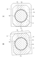
- FIG. 3 is a cross-sectional view taken along line AA in FIG. 2.
- A) is a disassembled perspective view of the doll body connecting device according to the second embodiment of the present invention
- B) is a diagram showing the fitting state of the connecting device.
- FIG. 1 is a front view of a doll body provided with a connecting device according to the present invention.
- the doll body is composed of a head 1, a trunk 4, a right arm 2, a left arm 3, a waist 7, a right leg 5, a left leg 6, and the like.
- the connecting device according to the present invention includes A, B, C, D parts on both shoulders and left and right arm parts, E, F, G parts on left and right waist parts, and H, Each part of I, J, K is connected.
- the doll body connecting device shown below connects a first member and a second member that constitute a part of the doll body, and is applied to all locations A to K in the figure.
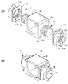
- FIG. 2A is an exploded perspective view of a shaft body having a shaft and a rotating member having a hole showing the first embodiment of the present invention
- FIG. is there. 2 (A) and 2 (B)
- the doll body connecting device is constituted by a shaft body 10 and rotating members 13 and 14.
- the shaft part main body 10 is a box-like body, and shaft parts 11 and 12 project from the side surfaces thereof.
- the rotating member 13 is provided with an engaging portion 13 d for fixing the rotating member 13 to the leg portion 5.
- the rotating member 14 is provided with an engaging portion 14 d for fixing the rotating member 14 to the waist 7.
- the rotating member 13 has a hole portion 13a into which the shaft portion 11 is inserted, and when the operator rotates the rotating member 13 in the circumferential direction of the shaft portion 11, a predetermined operational feeling (click) is given to the operator. It rotates while giving a feeling.
- the rotating member 14 has a hole 14a into which the shaft portion 12 is inserted, and gives a predetermined operational feeling to the operator when the operator rotates the rotating member 14 in the circumferential direction of the shaft portion 12. While rotating.
- the shaft portion 12 is formed with a recess 12a extending along the circumferential direction.
- a plurality of recesses 12 a are formed so as to be aligned in the axial direction of the shaft portion 12.
- the shaft portion 11 is formed with a recess extending along the circumferential direction.
- a plurality of concave portions are formed so as to be aligned in the axial direction of the shaft portion 11.
- projections 12b are formed at four locations so as to protrude from the peripheral surface.
- a protruding portion 11b is also formed on the peripheral surface of the shaft portion 11 so as to protrude from the peripheral surface.
- recesses 14b that fit into the protrusions 12b of the shaft portion 12 are formed side by side in the circumferential direction of the inner periphery of the multiple hole portions 14a.
- a first region where the concave portion 14b is formed and a second region 14c where the concave portion 14b is not formed are arranged in the longitudinal direction of the hole portion 14a (the axial direction when the shaft portion 12 is inserted). Is provided.
- recesses 13b that fit into the protrusions of the shaft 11 are formed side by side in the circumferential direction of the inner periphery of the multiple holes 13a.
- region 13c in which the recessed part 13b is not formed are located in a line with the longitudinal direction (axial direction when the axial part 11 is inserted) of the hole part 13a. Is provided.
- the hardness of the shaft portions 11 and 12 of the shaft portion main body 10 and the hardness of the rotating members 13 and 14 are formed with different hardnesses.
- the hardness of the shaft portions 11 and 12 of the shaft body 10 is formed to be greater than the hardness of the rotating members 13 and 14.
- the shaft portion main body 10 including the shaft portion 12 is made of, for example, polystyrene (PS), acrylonitrile / butadiene / styrene.
- PS polystyrene
- ABS acrylonitrile / butadiene / styrene
- it is formed of a material having a high hardness such as a mixture (ABS).
- ABS mixture
- the rotating members 13 and 14 are formed of a low hardness material, it is preferable to use polyethylene (PE) or the like as the low hardness material.
- PE polyethylene
- a rubber material elastomer, PVC
- the hardness difference may be such that the hardness of the rotating members 13 and 14 is greater than the hardness of the shaft portion 12 of the shaft body 10. Further, this hardness difference may be applied to the entire shaft body 10 including the shaft portions 11 and 12 alone, or the holes 13a and 14a may be formed only by the holes 13a and 14a. You may apply to the whole rotation member 13 and 14 including.
- FIG. 3 is a cross-sectional view taken along the line AA of FIG. 2, and FIG. 3B is a diagram in which the protrusion 12b formed on the shaft body 10 is fitted into the recess 14b formed in the hole 14a of the rotating member 12. It is a figure explaining the state which produces a click feeling by moving to the recessed part 14b next to the circumference direction of the inner periphery of the hole part 14a from the recessed part 14b currently fitted.
- the hardness of the shaft portion 12 of the shaft body 10 is formed to be greater than the hardness of the rotating member 14. Further, the hardness of the shaft portion 11 of the shaft body 10 is also made larger than the hardness of the rotating member 13.
- the hardness of the shaft portion 12 is larger than the hardness of the rotating member 14, when the rotating member 14 is rotated with respect to the shaft portion 12, the protruding portion 12b of the shaft portion 12 having a high hardness is deformed.
- the concave portion 14b of the rotating member 14 with low hardness is deformed due to its flexibility.
- the shaft portion 12 of the shaft portion main body 10 by forming the hardness of the shaft portion 12 of the shaft portion main body 10 to be larger than the hardness of the rotating member 14, the shaft portion 12 having a high hardness is not deformed and the rotating member 14 having a low hardness is deformed.
- the low-hardness rotating member 14 can be deformed with flexibility, and the fitting of the connecting portion between the hole portion 14a and the shaft portion 12 becomes flexible.
- connection parts A to K in FIG. 1 are used as connecting parts as in the connecting device in this embodiment, and the hardness of the shaft part of the shaft part body is higher than the hardness of the hole part of the rotating member. Can also be formed larger. Thus, if comprised, the effect
- FIG. 4A is an exploded perspective view of a doll body connecting device according to the second embodiment of the present invention
- FIG. 4B is a diagram showing a fitting state of the connecting device.
- the doll body connecting device is composed of a shaft body 16 and a rotating member 19.
- a shaft portion 17 is formed on the shaft body 16.
- the rotating member 19 has a hole portion 19a into which the shaft portion 17 is inserted, and gives a predetermined operational feeling to the operator when the operator rotates the rotating member 9 in the circumferential direction of the shaft portion 17. While rotating.
- the shaft portion 17 is formed with a concave portion 17a extending along the circumferential direction.
- a plurality of recesses 17 a are formed so as to be aligned in the axial direction of the shaft portion 17.
- projections 17 b are formed at four locations in the same manner as in Embodiment 1 so as to protrude from the peripheral surface.
- a recess 19b that fits with the protrusion 17b of the shaft 17 is formed side by side in the circumferential direction of the inner periphery of the multiple hole 19a.
- a first region in which the recess portion 19b is formed and a second region in which the recess portion 19b is not formed are arranged side by side in the longitudinal direction of the hole portion 19a (the axial direction when the shaft portion 17 is inserted). It has been.
- the hardness of the shaft portion 17 of the shaft portion main body 16 and the hardness of the rotating member 19 are different from each other.
- the hardness of the shaft portion 17 of the shaft portion main body 16 is made larger than the hardness of the rotating member 19.
- Other configurations are the same as those of the first embodiment.
Landscapes
- Toys (AREA)
Abstract
【課題】人形体の関節において、良好なクリック感を保持し、組立、分解時に連結部分の角部の破損を回避し、良好な組立て精度を簡単に得ることができ、さらには設計コストの安い人形体の連結装置を提供することを目的とする。 【解決手段】人形体の一部を構成する第1の部材と第2の部材を連結する連結装置であって、軸部を有する軸部本体と、軸部が挿入される穴部を有し、前記軸部に対して周方向に回転させた際に操作者に対して所定の操作感を与えながら回転する回転部材と、を備え、前記軸部本体の軸部の硬度と前記回転部材の硬度とを異なる硬度に形成した。特に、前記軸部本体の軸部の硬度を、前記回転部材の硬度よりも大きく形成した。
Description
本発明は、人形体に適用される連結装置に関する。
従来、人形体においては、その脚部等において、軸部を有する軸部本体と、当該軸部と嵌合する回転部材とを結合して構成した連結装置が、多く採用されている。また、連結装置において、操作者が軸部本体と回転部材を軸部を中心に相対的に回転させたとき、所定の回転量毎に若干の抵抗を感じる操作感、いわゆる「クリック感」が生じるような、クリック連結部を用いているものも数多く存在する。
たとえば特許文献1においては、軸部を多角軸とし、当該多角軸を可撓性合成樹脂素材で成型された略矩形枠状の部材に挿入した、クリック連結部が開示されている。このクリック連結部においては、略矩形枠状の部材の一対の長板が多角軸の辺に圧接しており、多角軸が略矩形枠状の部材に対して回転するときには、一対の長板を撓ませつつ回転することでクリック感が生じるようにしている。このように、軸部を回転させても略矩形枠状の部材の一部しか外側に撓まないので、壊れにくく且つ成形が容易という構造を採用し、かかる構造面の利点を狙っている。
しかしながら、従来の人形体の連結装置においては、軸部本体と回転部材とが同一硬度で形成されているが、このように構成すると、つぎのような問題点が生ずる。
即ち、(1)軸部本体と回転部材とが同一硬度である場合、嵌合が硬くなり過ぎて連結部にゆとりが無くなると回転時の抵抗が大きくなりすぎる可能性がある。また、連結部に使用を継続しているうちに、クリック感を生じさせるための箇所が磨耗し、クリック感が欠如する可能性がある。
(2)軸部本体と回転部材とが同一硬度である場合、組立、分解時に、全体の傾斜等の成形時の誤差があったときに、組立てが困難になるため組立て精度が低下し、また、連結部分の角部が破損し易い。
(3)従って、所定のクリック感を生じつつ、かつ、それが継続し、しかも組立て時に困難がなく破損もしづらく、組立て精度も低下しないようにするには、必然的に連結部分の寸法、形状を相当に吟味する必要があり、設計コストが高くなる。
(2)軸部本体と回転部材とが同一硬度である場合、組立、分解時に、全体の傾斜等の成形時の誤差があったときに、組立てが困難になるため組立て精度が低下し、また、連結部分の角部が破損し易い。
(3)従って、所定のクリック感を生じつつ、かつ、それが継続し、しかも組立て時に困難がなく破損もしづらく、組立て精度も低下しないようにするには、必然的に連結部分の寸法、形状を相当に吟味する必要があり、設計コストが高くなる。
そこで、本発明は前記の問題点に鑑みなされたものであり、人形体において、良好なクリック感を保持し、組立、分解時に連結部分の角部の破損を回避し、良好な組立て精度を簡単に得ることができ、さらには設計コストの安い人形体の連結装置を提供することを目的とする。
本発明はかかる課題を解決するもので、人形体の一部を構成する第1の部材と第2の部材を連結する連結装置であって、軸部を有する軸部本体と、軸部が挿入される穴部を有し、前記軸部に対して周方向に回転させた際に操作者に対して所定の操作感を与えながら回転する回転部材と、を備え、前記軸部本体の軸部の硬度と前記回転部材の硬度とを異なる硬度に形成した。特に、前記軸部本体の軸部の硬度を、前記回転部材の硬度よりも大きく形成した。
本発明によれば、軸部の硬度と、該軸部に連結される回転部材の硬度とを異なる硬度にしたことにより、硬度の高い部材(例えば軸部本体)に比べて、硬度の低い部材(例えば回転部材)は柔軟性があるため、硬度の高い部材側に沿って変形するようになる。従って、連結装置の組立て時や、回転部材を軸部に対して回転させた時に、低硬度の部材の変形によって連結部にゆとりが生じる。これにより、回転時の抵抗は大きくなりすぎないようにすることができる。また、組立時に、硬度の低い側が柔軟性を持って変形でき、連結部分の嵌合が柔軟となる。従って組立、分解時に、組立て精度を向上できるとともに、連結部分の角部の破損も回避できる。すなわち、連結部分の寸法、形状について比較的吟味しなくとも良くなるため、設計コストを低減できる。
また、本発明は、上記構成において、前記軸部の周方向に形成され、前記回転部材と嵌合する突起部と、前記穴部に形成され、前記軸部の突起部と嵌合する凹部とを有し、前記穴部は、軸方向に沿って前記凹部が形成された第1領域と前記凹部が形成されていない第2領域が設けられている。
本発明によれば、軸部本体の軸部の硬度と回転部材の硬度とを異なる硬度に形成することで、硬度の高い側と硬度の低い側の間の連結部分に、回転時や組立て時に硬度の低い側の変形によってゆとりが生じる。このゆとりにより、回転時の抵抗は大きくなりすぎないようにすることができる。また、組立時に、硬度の低い側が柔軟性を持って変形でき、連結部分の嵌合が柔軟となる。従って組立、分解時に、組立て精度を向上できるとともに、連結部分の角部の破損も回避できる。さらに、すなわち、連結部分の寸法、形状について比較的吟味しなくとも良くなるため、設計コストを低減できる。
以下、図面を参照して本発明の実施形態について詳細に説明する。
(第1実施形態)
(第1実施形態)
図1は、本発明に係る連結装置を備えた人形体の正面図である。図1において、人形体は、頭部1、胴部4、右腕部2、左腕部3、腰部7、右脚部5及び左脚部6等により構成されている。また、本発明に係る連結装置は図1において、両肩及び左右の腕部にA,B,C,Dの各部、左右の腰部にE,F,Gの各部、左右の脚部にH,I,J,Kの各部が、連結されている。以下に示す、人形体の連結装置は、人形体の一部を構成する第1の部材と第2の部材を連結するものであって、図中A~Kの全箇所に適用される。
本発明の第1実施形態では、連結部A~Kの内、人形体の脚部5と腰部7との連結部Gを例に取り、説明する。
図2(A)は、本発明の第1実施形態を示す軸部を有する軸部本体と穴部を有する回転部材との分解斜視図、(B)は連結装置の嵌合状態を示す図である。図2(A)及び(B)において、人形体の連結装置は、軸部本体10と回転部材13、14によって構成されている。軸部本体10は箱状体で、その側面より軸部11、12が突出形成されている。回転部材13には、脚部5に回転部材13を固定するための係合部13dが設けられている。また、回転部材14には、腰部7に回転部材14を固定するための係合部14dが設けられている。回転部材13は、軸部11が挿入される穴部13aを有し、操作者が回転部材13を軸部11の周方向に回転させた際に、操作者に対して所定の操作感(クリック感)を与えながら回転するものである。回転部材14は、軸部12が挿入される穴部14aを有し、操作者が回転部材14を軸部12の周方向に回転させた際に、操作者に対して所定の操作感を与えながら回転するものである。
軸部12には、周方向に沿って延びる凹部12aが形成されている。また、凹部12aは、軸部12の軸方向に並ぶように、複数形成されている。軸部11も同様に、周方向に沿って延びる凹部が形成されている。また、凹部は、軸部11の軸方向に並ぶように、複数形成されている。軸部12の周面には、当該周面から突出するように、突起部12bが4箇所に形成されている。軸部11の周面にも、当該周面から突出するように、突起部11bが形成されている。
回転部材14の穴部14aの内周には、軸部12の突起部12bと嵌合する凹部14bが多数穴部14aの内周の円周方向に並んで形成されている。穴部14aは、凹部14bが形成された第1領域と凹部14bが形成されていない第2領域14cが、穴部14aの長手方向(軸部12が挿入された場合の軸方向)に並んで設けられている。この凹部14bが形成されていない第2の領域には、軸部12が挿入された場合には、その先端部分が位置する。また、同様に、穴部13aの内周には、軸部11の突起部と嵌合する凹部13bが多数穴部13aの内周の円周方向に並んで形成されている。穴部13aは、凹部13bが形成された第1領域と凹部13bが形成されていない第2領域13cが、穴部13aの長手方向(軸部11が挿入された場合の軸方向)に並んで設けられている。
ここで、軸部本体10の軸部11、12の硬度と回転部材13、14の硬度とを異なる硬度で形成している。この例では、軸部本体10の軸部11、12の硬度を、回転部材13、14の硬度よりも大きく形成している。
軸部本体10の軸部12の硬度を、回転部材14の穴部14aの硬度よりも大きく形成する場合、軸部12を含む軸部本体10を例えばポリスチレン(PS)、アクリルニトリル・ブタジエン・スチレンの混合物(ABS)などの高硬度の材料によって形成するのが好ましい。上記材料に限らず、構造面の寸法を合わせれば、他の高硬度材料も使用できる。
また、回転部材13、14を低硬度の材料で形成する場合、低硬度の材料としては、ポリエチレン(PE)などを用いるのが良い。尚、上記の他に、ゴム材(エラストマー、PVC)なども適用できる。尚、かかる硬度差は、上記とは逆に、回転部材13、14の硬度を、軸部本体10の軸部12の硬度よりも大きく形成しても良い。
また、この硬度差は、軸部11、12のみでも該軸部11、12を含む軸部本体10の全体に適用しても良く、また穴部13a、14aのみでも該穴部13a、14aを含む回転部材13、14の全体に適用しても良い。
また、この硬度差は、軸部11、12のみでも該軸部11、12を含む軸部本体10の全体に適用しても良く、また穴部13a、14aのみでも該穴部13a、14aを含む回転部材13、14の全体に適用しても良い。
図3は図2のA-A断面図であって、同図(B)は軸部本体10に形成された突起部12bが、回転部材12の穴部14aに形成された凹部14bに嵌合しており、現在嵌合している凹部14bから、穴部14aの内周の円周方向隣の凹部14bに移動することで、クリック感を生じさせる状態を説明する図である。本発明では、軸部本体10の軸部12の硬度を、回転部材14の硬度よりも大きく形成している。また、軸部本体10の軸部11の硬度も、回転部材13の硬度よりも大きく形成している。このように、軸部12の硬度を、回転部材14の硬度よりも大きくしたので、回転部材14を軸部12に対して回転させたとき、硬度の高い軸部12の突起部12bは変形せず、硬度の低い回転部材14の凹部14bは、柔軟性があるため変形するようになる。
従って、硬度の高い軸部12側と硬度の低い回転部材14の間の連結部分、つまり図3(B)のように、軸部12の突起部12bに対する低硬度の穴部14aの凹部14bの変形の増加によって、硬度の大きい軸部12の突起部12bに対して該穴部14aの凹部14bの変形量が大きくなって、円周方向のゆとりが生じるようになっている。。
また、上記のように、軸部本体10の軸部12の硬度を、回転部材14の硬度よりも大きく形成することにより、硬度の高い軸部12は変形せず硬度の低い回転部材14が変形することとなり、組立時に、低硬度の回転部材14が柔軟性を持って変形でき、穴部14aと軸部12との連結部分の嵌合が柔軟となる。
また、図1のA~Kの連結部の全部またはその半数以上を、本実施形態における連結装置のような連結部とし、軸部本体の軸部の硬度が、回転部材の穴部の硬度よりも大きく形成することもできる。この様に、構成すれば、人形体の全ての連結部において、上記と同様な作用、効果が得られる。
尚、上記とは逆に、硬度の高い部材を回転部材13、14とし、硬度の低い部材を軸部11、12としても、同様の作用、効果が得られる。
(第2実施形態)
(第2実施形態)
図4(A)は本発明の第2実施形態に係る人形体の連結装置の分解斜視図、(B)は連結装置の嵌合状態を示す図である。図4に示すように、人形体の連結装置は、軸部本体16と回転部材19によって構成されている。軸部本体16は、軸部17が形成されている。回転部材19は、軸部17が挿入される穴部19aを有し、操作者が回転部材9を軸部17の周方向に回転させた際に、操作者に対して所定の操作感を与えながら回転するものである。
軸部17には、周方向に沿って延びる凹部17aが形成されている。また、凹部17aは、軸部17の軸方向に並ぶように、複数形成されている。軸部17の周面には、当該周面から突出するように、突起部17bが実施形態1と同様に4箇所に形成されている。回転部材19の穴部19aの内周には、軸部17の突起部17bと嵌合する凹部19bが多数穴部19aの内周の円周方向に並んで形成されている。穴部19aは、凹部19bが形成された第1領域と凹部19bが形成されていない第2領域が、穴部19aの長手方向(軸部17が挿入された場合の軸方向)に並んで設けられている。
軸部本体16の軸部17の硬度と回転部材19の硬度とを異なる硬度に形成している。この例では、軸部本体16の軸部17の硬度を、回転部材19の硬度よりも大きく形成している。その他の構成は、第1実施形態と同様である。
以上、本発明の好ましい実施形態について述べたが、本発明は既述の実施形態に限定されるものではなく、実用新案登録請求の範囲に記載された本発明の要旨の範囲内において、各種の変更及び変形が可能である。
1 頭部
2 右腕部
3 左腕部
4 胴部
5 右脚部
6 左脚部
A~K 連結部
10 軸部本体
11、12 軸部
13、14 回転部材
14a 穴部
2 右腕部
3 左腕部
4 胴部
5 右脚部
6 左脚部
A~K 連結部
10 軸部本体
11、12 軸部
13、14 回転部材
14a 穴部
Claims (3)
- 人形体の一部を構成する第1の部材と第2の部材を連結する連結装置であって、
軸部を有する軸部本体と、
前記軸部が挿入される穴部を有し、前記軸部に対して周方向に回転させた際に操作者に対して所定の操作感を与えながら回転する回転部材と、を備え、
前記軸部本体の軸部の硬度と前記回転部材の硬度とを異なる硬度に形成したことを特徴とする人形体の連結装置。 - 前記軸部本体の軸部の硬度を、前記回転部材の硬度よりも大きく形成したことを特徴とする請求項1記載の人形体の連結装置。
- 前記軸部の周方向に形成され、前記回転部材と嵌合する突起部と、
前記穴部に形成され、前記軸部の突起部と嵌合する凹部とを有し、
前記穴部は、軸方向に沿って前記凹部が形成された第1領域と前記凹部が形成されていない第2領域が設けられていることを特徴とする請求項1または請求項2に記載の人形体の連結装置。
Priority Applications (1)
| Application Number | Priority Date | Filing Date | Title |
|---|---|---|---|
| CN201090001107.3U CN202682775U (zh) | 2009-11-04 | 2010-09-02 | 人偶躯体的连结装置 |
Applications Claiming Priority (2)
| Application Number | Priority Date | Filing Date | Title |
|---|---|---|---|
| JP2009-007851U | 2009-11-04 | ||
| JP2009007851U JP3156845U (ja) | 2009-11-04 | 2009-11-04 | 人形体の連結装置 |
Publications (1)
| Publication Number | Publication Date |
|---|---|
| WO2011055586A1 true WO2011055586A1 (ja) | 2011-05-12 |
Family
ID=43969826
Family Applications (1)
| Application Number | Title | Priority Date | Filing Date |
|---|---|---|---|
| PCT/JP2010/064991 Ceased WO2011055586A1 (ja) | 2009-11-04 | 2010-09-02 | 人形体の連結装置 |
Country Status (3)
| Country | Link |
|---|---|
| JP (1) | JP3156845U (ja) |
| CN (1) | CN202682775U (ja) |
| WO (1) | WO2011055586A1 (ja) |
Cited By (3)
| Publication number | Priority date | Publication date | Assignee | Title |
|---|---|---|---|---|
| WO2015170419A1 (ja) * | 2014-05-07 | 2015-11-12 | 株式会社バンダイ | 模型 |
| JP2016172162A (ja) * | 2016-07-07 | 2016-09-29 | 株式会社バンダイ | 模型 |
| JP2018057907A (ja) * | 2017-12-06 | 2018-04-12 | 株式会社バンダイ | 模型 |
Families Citing this family (5)
| Publication number | Priority date | Publication date | Assignee | Title |
|---|---|---|---|---|
| JP2012081085A (ja) * | 2010-10-12 | 2012-04-26 | Bandai Co Ltd | 人形体の関節構造 |
| JP5628001B2 (ja) * | 2010-11-17 | 2014-11-19 | 有限会社ダイスプロジェクト | 人形玩具の2段階関節部材及び人形玩具 |
| JP5653235B2 (ja) * | 2011-01-24 | 2015-01-14 | 株式会社マーゼンプロダクツ | 回動可能な連結構造、およびその連結構造を用いた情報表示用ホルダ |
| JP5753107B2 (ja) * | 2012-01-26 | 2015-07-22 | 株式会社バンダイ | 人形体の関節構造 |
| JP7462493B2 (ja) | 2019-04-26 | 2024-04-05 | 株式会社バンダイ | 連結パーツ、インジェクションキットおよび人型玩具 |
Citations (3)
| Publication number | Priority date | Publication date | Assignee | Title |
|---|---|---|---|---|
| JP3163255B2 (ja) * | 1996-05-31 | 2001-05-08 | 株式会社バンダイ | 連結装置及びその連結装置の製造方法並びに可動体及びその可動体の製造方法 |
| JP2007007174A (ja) * | 2005-06-30 | 2007-01-18 | Volks Inc | 人形の関節部材及び該関節部材を備えた人形 |
| JP3873217B2 (ja) * | 2003-08-05 | 2007-01-24 | 株式会社ボークス | 人形の関節構造及び該関節構造を有する人形 |
-
2009
- 2009-11-04 JP JP2009007851U patent/JP3156845U/ja not_active Expired - Lifetime
-
2010
- 2010-09-02 CN CN201090001107.3U patent/CN202682775U/zh not_active Expired - Lifetime
- 2010-09-02 WO PCT/JP2010/064991 patent/WO2011055586A1/ja not_active Ceased
Patent Citations (3)
| Publication number | Priority date | Publication date | Assignee | Title |
|---|---|---|---|---|
| JP3163255B2 (ja) * | 1996-05-31 | 2001-05-08 | 株式会社バンダイ | 連結装置及びその連結装置の製造方法並びに可動体及びその可動体の製造方法 |
| JP3873217B2 (ja) * | 2003-08-05 | 2007-01-24 | 株式会社ボークス | 人形の関節構造及び該関節構造を有する人形 |
| JP2007007174A (ja) * | 2005-06-30 | 2007-01-18 | Volks Inc | 人形の関節部材及び該関節部材を備えた人形 |
Cited By (6)
| Publication number | Priority date | Publication date | Assignee | Title |
|---|---|---|---|---|
| WO2015170419A1 (ja) * | 2014-05-07 | 2015-11-12 | 株式会社バンダイ | 模型 |
| JP2015213542A (ja) * | 2014-05-07 | 2015-12-03 | 株式会社バンダイ | 模型 |
| CN106102851A (zh) * | 2014-05-07 | 2016-11-09 | 株式会社万代 | 模型 |
| US9511301B2 (en) | 2014-05-07 | 2016-12-06 | Bandai Co., Ltd. | Model |
| JP2016172162A (ja) * | 2016-07-07 | 2016-09-29 | 株式会社バンダイ | 模型 |
| JP2018057907A (ja) * | 2017-12-06 | 2018-04-12 | 株式会社バンダイ | 模型 |
Also Published As
| Publication number | Publication date |
|---|---|
| CN202682775U (zh) | 2013-01-23 |
| JP3156845U (ja) | 2010-01-21 |
Similar Documents
| Publication | Publication Date | Title |
|---|---|---|
| JP3156845U (ja) | 人形体の連結装置 | |
| JP6323561B2 (ja) | ダストカバー | |
| JP5088075B2 (ja) | シールリング | |
| CN205613051U (zh) | 一种双头连接销及其积木组件 | |
| WO2013035486A1 (ja) | 人形玩具 | |
| WO2010079674A1 (ja) | 等速自在継手用ブーツおよび等速自在継手 | |
| CN205759722U (zh) | 一种连接销及其积木组件 | |
| JP6483776B2 (ja) | キーボードのキー用パンタグラフ構造 | |
| JP6744194B2 (ja) | 軸受保持構造およびモータ | |
| JP4929245B2 (ja) | 工具類のグリップ | |
| EP2843250B1 (en) | Shaft connection mechanism | |
| JP2006162016A (ja) | 等速ジョイント用ブーツ | |
| CN117666714B (zh) | 一种具有磁吸旋转功能的平板电脑壳体 | |
| JP2026512143A (ja) | 積み木システム、組み立て及び分解可能な積み木構造、並びにメスヘッド積み木 | |
| WO2010058764A1 (ja) | ヒンジ構造及び電子装置 | |
| JP5829419B2 (ja) | バタフライ弁の気密構造 | |
| CN101493114A (zh) | 一种汽车推力杆接头总成 | |
| JP2000152988A (ja) | 注射器の押し子 | |
| JP6445225B2 (ja) | インペラー | |
| CN216859557U (zh) | 具有卡抵结构的套筒 | |
| CN209057339U (zh) | 一种头戴耳机 | |
| JP2009019656A (ja) | カップリングダンパー | |
| JP7015206B2 (ja) | カープラグ用抜け止めユニットおよび電源ソケット | |
| KR100872202B1 (ko) | 축 회전 구조 및 이 구조를 사용한 멀티미디어 장치 | |
| JP5192132B2 (ja) | 等速ジョイント用ブーツ |
Legal Events
| Date | Code | Title | Description |
|---|---|---|---|
| WWE | Wipo information: entry into national phase |
Ref document number: 201090001107.3 Country of ref document: CN |
|
| 121 | Ep: the epo has been informed by wipo that ep was designated in this application |
Ref document number: 10828146 Country of ref document: EP Kind code of ref document: A1 |
|
| NENP | Non-entry into the national phase |
Ref country code: DE |
|
| 122 | Ep: pct application non-entry in european phase |
Ref document number: 10828146 Country of ref document: EP Kind code of ref document: A1 |