WO2011052062A1 - Information processing device, method, system, and program - Google Patents
Information processing device, method, system, and program Download PDFInfo
- Publication number
- WO2011052062A1 WO2011052062A1 PCT/JP2009/068619 JP2009068619W WO2011052062A1 WO 2011052062 A1 WO2011052062 A1 WO 2011052062A1 JP 2009068619 W JP2009068619 W JP 2009068619W WO 2011052062 A1 WO2011052062 A1 WO 2011052062A1
- Authority
- WO
- WIPO (PCT)
- Prior art keywords
- imaging
- signal light
- irradiation angle
- light
- shape
- Prior art date
Links
Images


Classifications
-
- A—HUMAN NECESSITIES
- A61—MEDICAL OR VETERINARY SCIENCE; HYGIENE
- A61B—DIAGNOSIS; SURGERY; IDENTIFICATION
- A61B3/00—Apparatus for testing the eyes; Instruments for examining the eyes
- A61B3/10—Objective types, i.e. instruments for examining the eyes independent of the patients' perceptions or reactions
-
- G—PHYSICS
- G01—MEASURING; TESTING
- G01B—MEASURING LENGTH, THICKNESS OR SIMILAR LINEAR DIMENSIONS; MEASURING ANGLES; MEASURING AREAS; MEASURING IRREGULARITIES OF SURFACES OR CONTOURS
- G01B9/00—Measuring instruments characterised by the use of optical techniques
- G01B9/02—Interferometers
- G01B9/02041—Interferometers characterised by particular imaging or detection techniques
- G01B9/02044—Imaging in the frequency domain, e.g. by using a spectrometer
-
- A—HUMAN NECESSITIES
- A61—MEDICAL OR VETERINARY SCIENCE; HYGIENE
- A61B—DIAGNOSIS; SURGERY; IDENTIFICATION
- A61B3/00—Apparatus for testing the eyes; Instruments for examining the eyes
- A61B3/10—Objective types, i.e. instruments for examining the eyes independent of the patients' perceptions or reactions
- A61B3/102—Objective types, i.e. instruments for examining the eyes independent of the patients' perceptions or reactions for optical coherence tomography [OCT]
-
- A—HUMAN NECESSITIES
- A61—MEDICAL OR VETERINARY SCIENCE; HYGIENE
- A61B—DIAGNOSIS; SURGERY; IDENTIFICATION
- A61B3/00—Apparatus for testing the eyes; Instruments for examining the eyes
- A61B3/10—Objective types, i.e. instruments for examining the eyes independent of the patients' perceptions or reactions
- A61B3/12—Objective types, i.e. instruments for examining the eyes independent of the patients' perceptions or reactions for looking at the eye fundus, e.g. ophthalmoscopes
-
- G—PHYSICS
- G01—MEASURING; TESTING
- G01B—MEASURING LENGTH, THICKNESS OR SIMILAR LINEAR DIMENSIONS; MEASURING ANGLES; MEASURING AREAS; MEASURING IRREGULARITIES OF SURFACES OR CONTOURS
- G01B9/00—Measuring instruments characterised by the use of optical techniques
- G01B9/02—Interferometers
-
- G—PHYSICS
- G01—MEASURING; TESTING
- G01B—MEASURING LENGTH, THICKNESS OR SIMILAR LINEAR DIMENSIONS; MEASURING ANGLES; MEASURING AREAS; MEASURING IRREGULARITIES OF SURFACES OR CONTOURS
- G01B9/00—Measuring instruments characterised by the use of optical techniques
- G01B9/02—Interferometers
- G01B9/02055—Reduction or prevention of errors; Testing; Calibration
- G01B9/02062—Active error reduction, i.e. varying with time
- G01B9/02067—Active error reduction, i.e. varying with time by electronic control systems, i.e. using feedback acting on optics or light
- G01B9/02068—Auto-alignment of optical elements
-
- G—PHYSICS
- G01—MEASURING; TESTING
- G01B—MEASURING LENGTH, THICKNESS OR SIMILAR LINEAR DIMENSIONS; MEASURING ANGLES; MEASURING AREAS; MEASURING IRREGULARITIES OF SURFACES OR CONTOURS
- G01B9/00—Measuring instruments characterised by the use of optical techniques
- G01B9/02—Interferometers
- G01B9/02083—Interferometers characterised by particular signal processing and presentation
-
- G—PHYSICS
- G01—MEASURING; TESTING
- G01B—MEASURING LENGTH, THICKNESS OR SIMILAR LINEAR DIMENSIONS; MEASURING ANGLES; MEASURING AREAS; MEASURING IRREGULARITIES OF SURFACES OR CONTOURS
- G01B9/00—Measuring instruments characterised by the use of optical techniques
- G01B9/02—Interferometers
- G01B9/0209—Low-coherence interferometers
- G01B9/02091—Tomographic interferometers, e.g. based on optical coherence
-
- G—PHYSICS
- G01—MEASURING; TESTING
- G01N—INVESTIGATING OR ANALYSING MATERIALS BY DETERMINING THEIR CHEMICAL OR PHYSICAL PROPERTIES
- G01N21/00—Investigating or analysing materials by the use of optical means, i.e. using sub-millimetre waves, infrared, visible or ultraviolet light
- G01N21/17—Systems in which incident light is modified in accordance with the properties of the material investigated
- G01N21/47—Scattering, i.e. diffuse reflection
- G01N21/4795—Scattering, i.e. diffuse reflection spatially resolved investigating of object in scattering medium
Definitions
- the present invention relates to an imaging support technique in tomographic imaging used for ophthalmologic medical care and the like.
- An eye tomographic imaging apparatus such as an optical coherence tomography (OCT) can three-dimensionally image the retinal layer. This is realized by emitting signal light to the retina, generating interference light from the return light of the signal light reflected or scattered at each layer or boundary of the retina and the reference light, and forming an image from the interference light Be done. This has attracted attention in recent years because the inside of the retinal layer can be observed to diagnose diseases more accurately.
- OCT optical coherence tomography
- C / D ratio which is the distance ratio between the edge of the depression of the optic disk called the cup and the edge of the disk called the disc, area, depth and volume of the cup, and the area between the inner limiting membrane and the outer limiting membrane
- the thickness of a certain nerve fiber layer is used as an indicator of the progress of glaucoma.
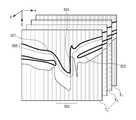
- FIG. 14 shows a schematic view of a tomogram of the optic papilla.
- T 1 to T n are two-dimensional tomograms (B-Scan images) of the optic papilla obtained by imaging the depth direction of the retina.
- One tomogram is composed of a plurality of scan lines (hereinafter referred to as A-scan lines) for scanning the depth direction of the retina.
- the z-axis represents the direction of this A-scan.
- Three-dimensional data consisting of T 1 to T n can be acquired by sequentially raster scanning a predetermined range of a plane (xy plane) on the retina. Since the retina has different light reflectance for each layer, the inner limiting membrane 1401, the retinal pigment epithelial layer 1402, the optic disc 1403 and the like can be identified by analyzing the image.
- Patent document 1 JP 2008-246158
- the shape of the optic papilla varies from person to person, and there are cases in which the disc is inclined at an angle to the surface of the retina as shown in FIG.
- the signal light is blocked at the entrance of the recess and the signal does not reach the inside sufficiently.
- the return light of the reflected or scattered signal light is attenuated, and a region where the signal becomes very weak as in the region 1404 is generated.
- the optic disc is not inclined, when the signal light is irradiated at an angle different from the direction of the depression, a region where the signal does not reach is generated.
- the layer structure can not be identified, and information necessary for diagnosis can not be obtained.
- Patent Document 1 discloses a technique for shooting by changing the irradiation position by preliminary shooting. However, since this technique is a technique for avoiding an area where the intensity of signal light is weak such as cataract, it is not a technique aimed at imaging a region to be imaged.
- the present invention has been made to solve the above problem, and according to the shape of at least a part of the object to be photographed, the signal light is irradiated so that the return light of the signal light irradiated to the object to be photographed has a predetermined intensity Having a determination means for determining an angle, and an instruction means for instructing imaging of a tomographic image of the imaging target based on return light of the signal light emitted to the imaging target at the determined irradiation angle. It features.
- signal light is irradiated from an angle at which the imaging target has a predetermined signal intensity according to the shape of at least a part of the imaging target to obtain a tomogram. Possible tomograms can be obtained.
- FIG. 1 is a block diagram of an OCT imaging system according to a first embodiment. It is a figure which shows the relationship between the positional relationship of a pupil and signal light, and the irradiation angle of signal light to a retina.
- FIG. 1 is a functional block diagram of an OCT imaging system according to a first embodiment.
- 5 is a flowchart showing the processing procedure of the information processing apparatus 102 according to the first embodiment. It is a figure explaining surface shape extraction of an optic nerve papilla. It is a flowchart which shows the process sequence of step S406. It is a figure which shows the gradient map of the optic disc by pre-irradiation angle (theta) PRE .
- FIG. 7 is a functional block diagram of an OCT imaging apparatus according to a second embodiment.
- FIG. 10 is a flowchart showing the processing procedure of the information processing apparatus 102 according to the second embodiment.
- FIG. 13 is a functional block diagram of an OCT imaging apparatus according to a third embodiment.
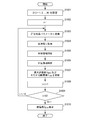
- FIG. 16 is a flowchart showing the processing procedure of the information processing apparatus 102 according to the third embodiment.
- the irradiation angle of signal light to the layer or interface of the retina is adjusted to obtain an image suitable for diagnosis of the retina and image measurement.
- the mechanism for acquiring an image will be described.
- the example applied to the tomogram acquisition of the depression of the optic disc will be described.
- a three-dimensional tomogram of the optic papilla is imaged once using OCT imaging, and the shape of the depression of the optic papilla is analyzed from the imaged tomogram.
- the irradiation angle of the signal light at which the intensity of the return light of the signal light reflected or scattered at each point of the analyzed recess is a predetermined value is determined. Further, by instructing imaging based on the determined irradiation angle, an image corresponding to the shape of the depression of the optic disc can be acquired.
- FIG. 1 is a block diagram of an OCT imaging system according to the present embodiment.
- FIG. 2A is a diagram showing the positional relationship between the pupil and the signal light
- FIGS. 2B and 2C show the relationship between the position of the signal light on the pupil and the irradiation angle of the signal light to a predetermined position.
- FIG. FIG. 3 is a functional block diagram of an OCT imaging system.
- FIG. 5 is a view for explaining surface shape extraction of the optic papilla.
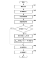
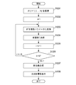
- FIG. 6 is a flowchart showing the processing procedure of the information processing apparatus 102.
- FIG. 7 is a diagram showing a gradient map of the optic disc with the pre-irradiation angle ⁇ PRE .
- FIG. 8 is a diagram showing a gradient map in which the luminance distribution is isized by adjusting the irradiation angle.
- the configuration of the OCT imaging system will be described with reference to FIG.
- the OCT imaging system receives an instruction from the information processing apparatus 102 that instructs the imaging unit 101 to perform imaging, and the signal light emitted to the imaging target is interfered with the return light of the signal light reflected or scattered and the reference light. It generates light and forms a tomogram.
- the return light of the signal light refers to light which the signal light irradiated to the object to be photographed is reflected or scattered at a predetermined layer or boundary, and detected by the imaging unit 101 as a signal.
- the information processing apparatus 102 acquires the captured tomographic image, and after performing predetermined image processing, displays the image on the display unit 103.
- the configuration of the imaging unit 101 is shown.
- the imaging unit 101 is an optical tomographic imaging apparatus using optical interference imaging.
- the image forming unit 104 controls the galvano mirror drive mechanism 105 using the instruction information from the information processing apparatus 102 as an imaging parameter, and drives the galvano mirror 106.
- the light beam from the low coherence light source 107 is divided by the half mirror 108 into the signal light traveling toward the eye 110 via the objective lens 109 and the reference light traveling toward the fixed reference mirror 111.
- the return light of the signal light reflected or scattered by the subject eye 110 and the return light of the reference light reflected by the reference mirror 111 are superimposed to generate interference light.
- an optical coupler having the functions of both a splitter for splitting light and a coupler for superposition may be used.
- the interference light is split into wavelength components of wavelengths ⁇ 1 to ⁇ n by the diffraction grating 112, and each wavelength component is detected by the one-dimensional optical sensor array 113.
- Each photosensor configuring the one-dimensional photosensor array 113 outputs a detection signal of the light intensity of the detected wavelength component to the image reconstruction unit 114.
- the image reconstruction unit 114 Based on the detection signal of each wavelength component of the interference light output from the one-dimensional light sensor array 113, the image reconstruction unit 114 determines the wavelength-light intensity relationship of the interference light, that is, the light intensity distribution of the interference light ( Determine the wavelength spectrum).
- the wavelength spectrum of the determined interference light is subjected to Fourier transform to reconstruct a tomogram of the retina.
- the imaging unit 101 can change the incident angle of the signal light to be irradiated to the site to be imaged. This will be described later.
- the position control unit 115 controls the imaging unit driving mechanism 116 using the instruction information from the information processing apparatus 102 as an imaging parameter to drive the image forming unit 104.
- the instruction information indicates the incident position on the xy plane of the signal light with respect to the pupil on the subject's eye, and the imaging unit driving mechanism 116 causes the subject's eye 110 to receive the signal light
- the image forming unit 104 is moved in parallel.
- the imaging unit 101 itself may be moved in parallel. Thus, by adjusting the relative position of the signal light incident on the pupil center and the pupil, the irradiation angle of the signal light to the target site on the retina can be changed.
- the configuration of the information processing apparatus 102 will be described.
- the information processing apparatus 102 instructs the imaging unit 101 to designate a first irradiation angle to perform imaging, and designates a second irradiation angle based on the imaged tomographic image to perform imaging. It is what gives instructions.
- the information processing apparatus 102 is connected to a CPU 118, a RAM 119, a ROM 120, a mouse 121 as an input device, and an HDD 122 as a storage unit via a bus 117.
- the ROM 120 stores a computer program for realizing the process shown in FIG. 7 described later.
- the program is expanded in the RAM 119 and executed by the CPU 118, whereby the program and each element of the information processing apparatus 102 cooperate to realize the function shown in FIG.
- the process described in 7 is realized.
- FIG. 2A is a schematic view showing the relationship between the pupil center and the position of signal light incident on the pupil.
- E 1 in FIG. 2A indicates the pupil
- P 0 indicates the pupil center
- IR 0 indicates the center point of the infrared image.
- the image of the pupil can be acquired, for example, by an infrared camera.
- the incident position P L of the signal light irradiated to the retina of the eye is adjusted in advance so as to coincide with the center of the pupil image.
- the incident position of the signal light is preferably coincident with the center of the pupil, but the center of the pupil and the irradiation position of the signal light are different without detailed alignment as shown in FIG. May be
- the contrast difference becomes large in the pupil region and the peripheral region
- the contour of the pupil E 1 can be extracted by detecting the image gradient. Since the contour of the pupil E 1 can be approximated to a circle, the center and the radius of the approximated circle are determined as the pupil center P 0 and the pupil radius r, respectively.
- the xy coordinates of the point P L when the point P 0 is the origin are (x L , y L ).
- FIG.2 (b) is a figure which shows the relationship between the signal light which injects on a pupil, and the irradiation angle to an object site
- E 1 is a pupil
- E 2 is a cornea
- E 3 is an eye
- E 4 is a lens
- MC is a macular region
- DC is an optic disc
- P 0 is a pupil center
- D 0 is a pupil center
- ⁇ LIM is the limit angle of the signal light.
- D 0 is referred to as a reference irradiation direction.
- l is the length of the line segment P 0 ⁇ MC.
- the length of l may be measured in advance by an axial length test, or a general average value may be used. Specifically, when the pupil radius r is 3 to 4 mm and the line segment D 0 ⁇ MC is 18.5 mm, ⁇ LIM is approximately 7.7 to 10.7 °.
- E 1 , DC, P 0 , D 0 and ⁇ LIM represent the same as (a).
- L is the centerline of the signal light
- P L is the signal light L is incident on the E 1 position
- theta is the point P L
- P 1 is the outline of E 1 Top reference point.
- ⁇ 1 is an angle formed by line segment P 0 P 1 and line segment P 0 P L on E 1
- ⁇ 2 is line segment P 0 ⁇ DC (direction D 0 ) and line segment P L ⁇ DC (direction D It is the corner that ⁇ ) makes.
- the value of theta 1 and theta 2 is determined by the position of the point P L, when the coordinates of the point P L is (x L, y L), determined by equation (2) and (3).
- ⁇ 2 is calculated from the angle when the signal light is focused on MC (angle formed by line segment P 0 ⁇ MC and line segment P L ⁇ MC) There is.
- An irradiation angle having these ( ⁇ 1 , ⁇ 2 ) as an angle component is defined as ⁇ .
- changing the incident position of the signal light on the retina by changing the incident position of the signal light on the pupil while keeping the incident direction on the pupil, changing the incident angle of the signal light on the retina without changing the region irradiated with the signal light it can.
- changing the incident angle even when an accurate shape can not be obtained in the case of irradiation from the first irradiation angle, it is possible to image from the second irradiation angle by being incident.
- the imaging instruction unit 301 transmits an imaging instruction to the imaging unit 101 to perform imaging at a predetermined irradiation angle to the retina.
- the information transmitted here is imaging conditions such as an irradiation angle. Reception of this shooting instruction is a condition for starting shooting. The determination process of the first irradiation angle performed by the imaging instruction unit 301 will be described later.
- the tomogram acquisition unit 302 acquires a tomogram imaged by the imaging unit 101 based on the imaging condition specified by the imaging instruction unit 301.
- the shape analysis unit 303 analyzes the layer structure of the tomogram acquired by the tomogram acquisition unit 302 to specify the shape of the recess.
- the layer structure analysis is performed based on the edge obtained from the luminance information obtained from the tomogram. For the portion where the shape could not be identified, the shape is estimated by interpolation. This process will be described later with reference to FIG.
- the re-imaging determination unit 304 determines whether re-imaging is to be performed based on the presence or absence of a partial region that can not be identified from the lack of the reflected light or the scattered return light in the recessed portion, or the size of the region. In the determination, the recessed portion is divided into predetermined small areas to obtain the intensity of return light for each small area, and an area where the signal strength of the small area is smaller than a predetermined threshold is detected. If there is a detected area, or if the area is larger than a predetermined size, it is determined that re-imaging is to be performed. This process will be described later with reference to FIG.
- the re-imaging determination unit 304 determines that the re-imaging determination unit 304 determines that re-imaging is to be performed, irradiation is performed such that the return light irradiated to the recess is a predetermined intensity based on the shape of the recess to be captured. Determine the angle.
- the predetermined intensity refers to the intensity of the return light that allows the shape analysis unit 303 or the user to accurately identify the shape of the recess, and the size of the region of the recess where the intensity of the return light of the signal light is less than the reference. Strength to minimize the The reference is determined by the shape analysis algorithm used in the shape analysis unit 303 or by user specification. Based on the determined irradiation angle, the imaging instruction unit 301 instructs reimaging.
- the display unit 103 displays the recaptured tomographic image.
- the storage unit 306 stores the information of the imaging instruction transmitted to the imaging unit 101 and the tomographic image acquired.
- the irradiation angle at which the intensity of light irradiated to the object to be imaged is equal to or less than the predetermined value is determined according to the analysis result of the shape, and imaging is instructed based on the determined irradiation angle. It is possible to reduce the area not drawn as an image for the object. In addition, since the shape of the concave portion to be imaged is analyzed based on the tomographic image captured first, and it is determined whether or not to recapture imaging according to the result, it is possible to reduce imaging waste.
- the imaging instruction unit 301 generates instruction information (hereinafter referred to as instruction information 1) for adjusting the two-dimensional measurement range and measurement depth of the fundus of the eye to be examined.
- the instruction information 1 is, for example, specified by the user via the mouse 121. However, information stored in the storage unit 306 may be used.
- the imaging instruction unit 301 generates instruction information (hereinafter referred to as instruction information 2) for adjusting the incident position of the signal light to the pupil of the eye to be examined.
- the instruction information 2 is information for instructing ⁇ PRE which is an irradiation angle of signal light to the retina of the eye to be examined.
- the imaging instruction unit 301 transmits the instruction information 1 and the instruction information 2 to the imaging unit 101.
- the value of ⁇ PRE is not particularly limited, and a predetermined value may be used in the device, or fine adjustment may be performed by user's designation. In short, signal light may be delivered to the retina of the fundus.
- Step S402 in response to receiving the instruction information 1 and 2, the imaging unit 101 captures a tomographic image using the instruction information 1 and the instruction information 2 acquired from the imaging instruction unit 301 as imaging conditions.
- Image data I of an imaged tomographic image in which the image forming unit 104 is moved by the position control unit 115 and the imaging unit driving mechanism 116 and the signal light is incident on the position on the pupil according to the first irradiation angle ⁇ PRE.
- the instruction information 1 and the instruction information 2 do not have to be conditions for the start of imaging.
- the imaging instruction unit 301 may transmit instruction information 1 and 2 as imaging conditions to the imaging unit 101, and notify the user that imaging preparation has been completed. In this case, the user can execute imaging at a desired timing.
- step S403 the shape analysis unit 303 acquires the image data I of the tomogram stored in the storage unit 306, and extracts the surface shape of at least a part of the optic disc region from the image data I.
- the optic nerve papilla is extracted as the boundary surface (inner limiting membrane) of the retina in the portion where the retinal pigment epithelial layer is not present.
- FIG. 5 the analysis procedure of the surface shape of the optic papilla in the tomogram performed by the shape analysis unit 303 and the region near the surface will be described.
- B-Scan images T 1 to T n are obtained, and the inner limiting membrane 501, the retinal pigment epithelial layer 502, the papillary area 503, and the area 504 where the image signal is very weak are shown.
- the inner limiting membrane 501 which is one of the boundary surfaces of the retinal layer is extracted.
- the inner limiting membrane 501 is the upper boundary of the retinal layer area (white area in the figure) and the background area (gray area in the figure), and has a feature that the contrast difference of luminance is large.
- the difference can be detected. For example, scanning is performed in the z-axis positive direction from the point where the z coordinate is 0 for each A scan line, and the scan is stopped at a point where the gradient of the luminance value of the image is a certain threshold Th 1 or more. Detect points A scan line number
- a point of the inner boundary film 501 corresponding to the line i is defined as p i .
- the continuity of the retinal layer area is interrupted in the z-axis direction, and the z-axis coordinate between two points on the adjacent inner limiting membrane 501 is largely changed.
- these two adjacent points are interpolated by a line.
- linear interpolation is applied.
- the region 504 can be compensated by a straight line substantially parallel to the z-axis.
- the retinal pigment epithelial layer 502 is extracted.
- the retinal pigment epithelial layer 502 is drawn as an area with particularly high brightness inside the retinal layer region, so it can be detected using the contrast in the retinal layer. For example, scanning is performed in the z-axis positive direction starting from the point p i for each A scan line i, and the scan is stopped at a point where the image gradient first becomes a certain threshold Th 2 or more. Detect the point of This point is defined as q i . At this time, since the nipple area 503 does not exist retinal pigment epithelium layer 502, if unable to detect the point q i, the coordinates of the point q i to a value F representing "not exist".
- the papillary area 503 can be detected as an area of the x coordinate of the point q i where the value F is stored. Then, a set of points p i included in the detected papillary area 503 is obtained for all T 1 to T n , and is used as surface shape data S of the optic disc.
- Step S404 the re-imaging determination unit 304 determines whether re-imaging should be performed based on the image data I and the shape data S acquired from the shape analysis unit 303. This determination is performed according to the size of the area where the intensity of the signal irradiated to the recess is small or the presence or absence of the area.
- Region 505 in FIG. 5 represents the retinal layer region near inner limiting membrane 501.
- the area 505 is obtained as an area (not including the background area above the inner boundary film 501) which is included in a range within a predetermined distance d from all points on the shape data S.
- the region 505 is divided into a plurality of local regions.
- the division number is k
- the volume of the region 505 is equally divided
- each region is R 1 to R k .
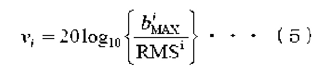
- a luminance evaluation value v i for evaluating whether the image signal is large is calculated by equation (4).
- Equation (4) m is the number of pixels included in R i , and b (j) is the j-th pixel included in R i
- b i MAX is the maximum luminance value included in R i
- RMS i is the value of RMS (Root Mean Square) calculated within R i .
- the luminance evaluation value V in the entire area 505 is calculated by the equation (6).
- the minimum value of the luminance evaluation value v i calculated for each local region as the luminance evaluation value V of the entire region 505, focusing on the presence or absence of the region where the intensity of the image signal is partially small.
- the evaluation value of can be obtained.
- the image data I and the value of the luminance evaluation value V obtained as a result of analysis are transmitted to the re-photographing determination unit 304.
- the method of determination is not limited to this.
- FIG. the luminance value of the recess is used, but as long as the shape of the recess can be identified, it is not necessary to re-capture, so waste of imaging can be reduced.
- instruction information 1 the image data I and information for permitting display of the image data I
- the size of the area where the intensity of the image signal is small may be used as the evaluation value. In this case, it is determined whether or not to recapture by changing the size threshold, and therefore, it is necessary to balance the time required for recapture with the accurate image information obtained by recapture. Can.
- Step S406 when the re-imaging angle determination unit 305 acquires the instruction information 2 from the re-imaging determination unit 304, the re-imaging angle determination unit 305 acquires the value of the pre-emission angle ⁇ PRE at the time of tomographic image acquisition in step S402 from the storage unit 306.
- the intensity of the return light of the signal light is desired
- the incident position P L : (x L , y L ) of the signal light on the pupil of the eye to be examined is obtained from the acquired irradiation angle ⁇ MAX and is transmitted to the imaging unit 101 as instruction information 3.
- the irradiation angle at which the surface area on the optic papilla is minimized is taken as ⁇ MAX when the signal light is not irradiated (or the intensity of the reflected light obtained from the subject's eye becomes extremely weak after irradiation). This process will be described later using the flowchart of FIG.
- step S407 the re-imaging angle determination unit 305 converts the irradiation angle ⁇ MAX obtained in step S910 into an imaging parameter. Specifically, contrary to the processing described in step S402 for converting the point P L (x L , y L ) on which the signal light on the retina is incident into the irradiation angle ⁇ : ( ⁇ 1 , ⁇ 2 ), Convert from angle ⁇ to point P L. This conversion can be performed by the following equations (7) and (8).
- r is the pupil radius
- l is the line segment P 0 ⁇ MC, as in step S402.
- the photographing instruction unit 301 transmits to the image pickup section 101.
- Step S408 the imaging unit 101 captures a tomographic image using the instruction information 2 acquired from the re-imaging angle determination unit 305 as an imaging parameter, and acquires image data I of the tomographic image.
- the imaging method is the same as step S402.
- the position control unit 115 and the imaging unit drive mechanism 116 are used as a means for changing the irradiation angle of the signal light to the target site from the first irradiation angle ⁇ PRE to the second irradiation angle ⁇ MAX . To move, but not limited to.
- means for changing the incident position of the signal light to the pupil may be used by changing the position of the fixation lamp to be presented to the subject's eye, and fixing the position at that position to rotate the subject's eye.
- the device configuration is simplified. Then, image data I of the acquired tomographic image and instruction information 1 for permitting display are transmitted to the display unit 103.
- Step S409 When the display unit 103 acquires the instruction information 1 from the re-photographing determination unit 304 or the imaging unit 101 in step S409, the display unit 103 displays the image data I acquired in the same manner on the display unit 103.
- the shape of the depression of the optic papilla is analyzed from the three-dimensional tomogram of the optic papilla imaged based on the first angle ⁇ PRE .
- a tomogram is re-imaged by determining an irradiation angle ⁇ MAX which is a second angle that minimizes a region where the intensity of the signal light irradiated to the recess falls below the reference according to the result.
- ⁇ MAX is a second angle that minimizes a region where the intensity of the signal light irradiated to the recess falls below the reference according to the result.
- step S406 acquiring the irradiation angle ⁇ MAX will be described in detail with reference to the flowchart of FIG.
- the intensity of the signal light at each point of the recess is determined for each irradiation angle, and the irradiation angle is selected such that the region where the intensity is smaller than a predetermined threshold is minimized. It is a process to obtain as ⁇ MAX .
- the intensity of the signal light at each point of the recess is determined by determining the angle between the light beam of the signal light and the slope of the shape of each point in the recess.
- step S601 the re-imaging angle determination unit 305 acquires the preliminary irradiation angle ⁇ PRE from the storage unit 306, and associates the reference irradiation direction D 0 with the image data I of the tomographic image.
- step S602 the re-imaging angle determination unit 305 sets the number of times of change of the irradiation angle to N , sets the irradiation angles ⁇ 1 to ⁇ N to be changed based on the reference irradiation direction D 0 and stores the same in the storage unit 306.
- the angular components ( ⁇ 1 , ⁇ 2 ) of ⁇ are
- the 0 ° ⁇ 360 ° N 1 is equally divided, in turn ⁇ 1 1, put a ⁇ ⁇ 1 j, ⁇ ⁇ 1 N1 and the number.
- the 0 ° ⁇ ⁇ LIM N 2 equal portions, sequentially theta 2 1, put ⁇ ⁇ 2 k ⁇ ⁇ 2 N2 and number.
- step S603 the rephotographing angle determination unit 305 determines the processing number for changing the irradiation angle.
- i is set to 1 and shape data S is acquired.
- Step S604 the re-photographing angle determining unit 305 obtains the irradiation angle theta i from the storage unit 306.
- Step S605 re-imaging angle determining unit 305, based on the irradiation angle theta i, analyzes the gradient information similarly obtained shape data S, to generate a gradient map GM .THETA.i shape data S.
- This gradient map represents the angle between the luminous flux of the signal light to be irradiated and the gradient at each point of the recess.
- the surface area of the optic papilla in the tomogram is depicted at a higher luminance as the intensity of the reflected light acquired as it passes through the pupil of the subject's eye increases as it is reflected at each local area on the surface when signal light is irradiated. Be done. Then, the intensity of the reflected light for each local area increases as the signal light is irradiated at an angle closer to perpendicular to the surface of the local area, because the difference between the light irradiation angle and the reflection angle decreases. This relationship will be described in other words with reference to FIG.
- the l edge in FIG. 7 represents a tangent in a certain local region on the shape data S
- BL ⁇ P represents a plane perpendicular to the irradiation direction of the signal light (D ⁇ P in this figure).
- This plane is defined as a projection reference plane of the signal light.
- h represents the height of the local region with respect to the projection reference plane.
- this tangent l edge is equal to the change in height h of the local region with respect to the projection reference plane, that is, the shape gradient.
- the concrete production method of gradient map GM ⁇ i is shown.
- the projection reference plane described above is divided into a plurality of local regions.
- the local area is divided into areas A 1 to A NA as rectangular areas A j of the same size.
- h j be the value of A map holding this value h j as a luminance value for each area A j is generated, and this is defined as a shape map.
- the brightness gradient g j of each brightness value h j of this shape map is calculated.
- g j is calculated using a Sobel filter.
- a map that holds the calculated value g j as a luminance value for each area A j is generated, and this is defined as a gradient map. In this way, the angle formed by the inclination at each point of the recess with respect to the signal light is determined.
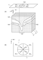
- FIG. 7 is a diagram showing a gradient map (described later) of the optic disc with the pre-irradiation angle ⁇ PRE .
- FIG. 7 shows the reference irradiation direction D 0 and the irradiation direction D ⁇ P of the signal light irradiated at the preliminary irradiation angle ⁇ PRE . Since the image data I is an image captured by the signal light of the irradiation angle ⁇ PRE , D ⁇ P coincides with the z-axis direction. Therefore, the reference irradiation direction D 0 is associated with the image as a direction inclined by the angle ⁇ PRE with reference to the z axis.
- the angle ⁇ PRE is actually expressed in three dimensions having ( ⁇ 1 , ⁇ 2 ) as a component but in FIG. 7 it is expressed by an angle projected in two dimensions for simplicity.
- tomographic images T 1 to T n and a papillary area 703 are shown, and the inner limiting membrane belonging to the papillary area 703 is particularly shown as an inner limiting membrane 704 (corresponding to the shape data S).
- the shape map SM [theta] P of the boundary layer 704 representing the height h for each region
- the gradient map GM [theta] P of the boundary layer 704 is a differential value of the shape map SM [theta] P is shown.
- the gradient map GM ⁇ P represents the incident angle of the signal light in each partial area of the recess, and thus represents the intensity of the signal light in each partial area.
- x ′ and y ′ are coordinate axes on SM ⁇ P and GM ⁇ P .
- shape map SM ⁇ P the change in luminance is gentle from the map center in the x 'axis negative direction, but the change in luminance is intense from the map center in the x' axis positive direction. Therefore, in the gradient map GM ⁇ P , there is an area with extremely high luminance in the area to the right of the map center. This indicates that the portion corresponds to the portion of the inner boundary film 704 in which the inclination of the shape is substantially parallel to the irradiation direction D ⁇ P .
- Step S606 the re-photographing angle determining unit 305 calculates the gradient evaluation value G i based on the generated gradient map GM .theta.i.
- the evaluation value indicates the size of the region where the signal strength at each point of the recess is less than or equal to a predetermined threshold.
- the average value of the obtained gradient at step S605 is the number of regions is equal to or less than a predetermined threshold value and gradient evaluation value G i.
- the predetermined threshold value may be a value obtained by adding across the reciprocal of the gradient values in the entire region as the evaluation value G i.
- the predetermined threshold value here may be set in advance or may be specified by the user, and is changed in accordance with the shape analysis algorithm, the user's request, or the like.
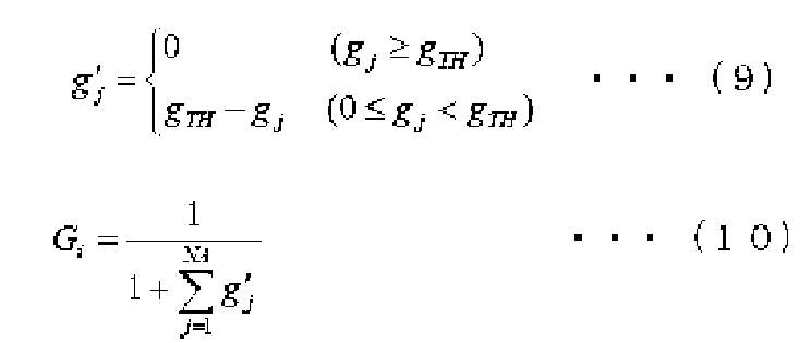
- the evaluation value G i of the surface area on the optic nerve head signal light is not irradiated is minimized, using the evaluation value, as follows. That is, the gradient value for each local region on the gradient map GM ⁇ i is g j , the constant gradient threshold is g TH, and the evaluation value G i is obtained by the equations (9) and (10).
- Equation (10) as the number of local regions where the gradient value falls below the g TH is small, and the value of the more amount of the gradient value is below the g TH small G i becomes larger, the value becomes smaller in the case of reverse.
- FIG. 8 is a diagram showing a gradient map when signal light is uniformly irradiated to the optic disc.
- T 1 to T n , 803, 804, and D 0 represent the same as in FIG. D .THETA.i the irradiation direction of the irradiated signal light irradiation angle ⁇ i, BL ⁇ i the irradiation angle theta i projection reference plane corresponding to, h is the reference plane BL .THETA.i the height of the boundary layer 804 on the basis, SM .THETA.i Is a shape map of the inner limiting film 804, and GM ⁇ i is a gradient map of the inner limiting film 804.
- T 1 to T n , 803, 804, and D 0 represent the same as in FIG. D .THETA.i the irradiation direction of the irradiated signal light irradiation angle ⁇ i, BL ⁇ i the irradiation angle theta i
- the gradient map GM ⁇ i has a luminance distribution with few local regions with extremely small gradient values.
- the evaluation value G i increases.
- the local region where the gradient value is extremely small increases, so the value of the evaluation value G i decreases.
- step S608 the re-photographing angle determination unit 305 increments the processing number i by one.
- step S609 the re-photographing angle determination unit 305 compares the processing number i with the number of changes N, and if i> N, the process proceeds to step S608, and otherwise proceeds to step S903.
- Modification 1 The following is a modification of the gradient evaluation value G i.
- G is suitable for ordinary depressions where the depressions are not curved.
- This gradient rating is particularly suitable for normal depressions in which the depressions are not curved.
- the fact that the recess is not curved means that the central axis of the recess is substantially straight. In such a case, the irradiation angle parallel to the central axis of the recess is ⁇ MAX .
- the property that signal intensity has isotropy with respect to the central axis of a recessed part is utilized.
- FIG. 8 shows a state in which the concave portion not having a complicated shape such as a curve is irradiated at an appropriate irradiation angle.
- the intensity of the signal light irradiated to the depressions of the inner boundary film 704 is isotropic, and the gradient map GM ⁇ i has such a luminance distribution that the area of equal luminance spreads like a ring from the map center. It becomes.
- the regions GMR 1 to GMR 4 have luminance distributions similar to each other.
- the evaluation value G i takes the average luminance values of the regions GMR 1 to GMR 4 as r 1 to r 4 respectively,
- r avg represents an average value of r 1 to r 4 .
- the values of G i increase as the values of r 1 to r 4 become uniform among the regions GMR 1 to GMR 4 , and the values decrease as the values of the regions become uneven.
- theta i is an isotropic with respect to the center of the recess, the value increases. It is possible to assume that the recessed portion is not curved and it is possible to use the evaluation value of this modification in the case of irradiation.
- Modification 2 In the second modification, the second irradiation angle is determined so that the signal intensity is the largest in the region where the signal intensity is small in the first tomographic image. In this case, the shape of the recess is accurately determined by displaying on the display unit 103 the first tomographic image obtained by the first irradiation angle and the second tomographic image obtained by the second irradiation angle. It can be confirmed. Further, tomograms may be synthesized using the configuration of the third embodiment described later. In this case, a tomographic image representing a more accurate shape can be obtained.
- the gradient evaluation value calculated by the re-imaging angle determination unit 305 in step S606 described above is a region obtained by complementing the shape of the tomographic image captured at the first irradiation angle ⁇ PRE without being accurately identified.
- the gradient evaluation value calculated by the re-imaging angle determination unit 305 in step S606 described above is a region obtained by complementing the shape of the tomographic image captured at the first irradiation angle ⁇ PRE without being accurately identified.
- it when light is irradiated most, it may be considered as high evaluation.
- Example 3 Although the irradiation angle of signal light was calculated
- the surface shape is analyzed by the following method to determine the irradiation angle ⁇ MAX . This will be described based on FIG.
- the deepest position of the recessed portion is detected from the shape data S of the recessed portion obtained by the shape analysis unit 303 of the first embodiment. This position is a point p D.
- the corresponding area of the papillary area 703 on the projection reference plane T ′ of the shape map is 703 ′, and the corresponding point of the point p D is p D ′.
- an irradiation angle ⁇ is acquired as ⁇ MAX such that the point p D ′ coincides with the center of gravity of the area 703 ′.
- the shape of the recess is specified from the tomogram by the OCT imaging apparatus, but specifying the shape by other methods does not prevent the application of the present invention.
- a plurality of tomograms are captured in advance at different irradiation angles, and the plurality of tomograms captured are analyzed to select a tomogram in which the tissue of the recess is best drawn on the image. indicate.
- one tomogram is selected from a plurality of tomograms imaged as follows.
- a plurality of tomograms are obtained from each of the signal lights emitted from different angles, and a three-dimensional surface shape of the optic disc is extracted from each of the tomograms, based on which an image in an internal region near the surface of the optic disc Find the magnitude of the signal.
- the method of determining the magnitude of the signal uses the same method as the luminance information analysis of the first embodiment.
- a tomogram with the largest image signal in this inner area is obtained and displayed. This is because as the amount of signal light reaching the recess increases, the signal appearing in the image also increases.
- FIG. 9 shows a functional configuration of the information processing apparatus 102 according to the present embodiment.
- the same functions as in the first embodiment are given the same reference numerals, and the description thereof is omitted.
- the photographing instruction unit 901 sets in advance a plurality of irradiation angles of the signal light to be irradiated to the depression of the retina.
- the imaging condition including the set information of the plurality of irradiation angles is transmitted to the imaging unit 101, and an instruction to perform imaging is performed.
- the selection unit 902 selects a tomogram having a small partial area in which the signal intensity in the area of the recess is smaller than a predetermined threshold value among the tomograms captured. This makes it possible to select an image that most appropriately represents the shape of the recess.
- the selected tomogram is displayed on the display unit 103.
- step S1001 the imaging instruction unit 901 generates instruction information 1.
- the number of times of change of the irradiation angle is N, and the irradiation angles ⁇ 1 to ⁇ N to be changed are set and held.
- the irradiation angles ⁇ 1 to ⁇ N are set by the same method as step S 602 in the first embodiment.
- ⁇ 1 to ⁇ N are set exhaustively in the range of possible values in step S 602, here, the change intervals of the angle may be set more roughly. This is for the purpose of acquiring a tomogram in which the tissue of the depression is generally imaged, in the present embodiment, instead of finding the optimum irradiation angle as in the first embodiment.
- the division number N 1 4 (0 ° ⁇ 360 ° with four equal parts) with respect to the angle component theta 1 of theta, the division number with respect to the angle component theta 2
- the instruction information 1 is transmitted to the imaging unit 101.
- step S1002 the photographing instruction unit 301 sets the processing number when changing the irradiation angle.
- Imaging instruction section 301 in step S1003 converts the irradiation angle theta i on the imaging parameters, this as instruction information 2, and transmits to the image pickup section 101.
- the conversion method is set in the same manner as step S407 in FIG.
- Step S1004 the imaging unit 101 captures a tomographic image using the instruction information 1 and the instruction information 2 acquired from the imaging instruction unit 301 as imaging parameters.
- the imaging method is the same as in step S402, and thus the description thereof is omitted.
- the image data of the tomographic image corresponding to the irradiation angle theta i captured is defined as I i.
- Tomographic image acquisition unit 302 acquires the image data I i captured from the imaging unit 101, and stores in the storage unit 306.
- step S1005 the shape analyzing portion 303 acquires the image data I i stored in the storage unit 306, and extracts the surface shape of the optic papilla from the image data I i.
- the extraction method is the same as in step S403, and thus the description thereof is omitted.
- the extracted surface shape data is defined as S i.
- the image data I i and the extracted shape data S i are transmitted to the luminance information analysis unit 1305.
- step S1006 the selection unit 702 analyzes the luminance information on the basis of the image data I i and the shape data S i obtained from the shape analyzing portion 303 obtains the luminance evaluation value V i.
- the method of obtaining V i is the same as in step S404, and thus the description thereof is omitted.
- the value of the luminance evaluation value V i is stored in the storage unit 306.
- step S1008 the photographing instruction unit 901 increments the processing number i by one.
- step S1009 the imaging instruction unit 901 compares the processing number i with the number of changes N. If i> N, the image data I MAX is acquired from the storage unit 306 and transmitted to the display unit 103, and then the step It transfers to S1010. If i ⁇ N, the process proceeds to step S1003.
- step S1010 the display unit 103 displays the image data I MAX selected by the selection unit 702 on a monitor (not shown).
- a plurality of tomograms are captured in advance at different irradiation angles, and a tomogram that maximizes the image signal of the surface tissue of the optic disc including the depression is selected and displayed. Therefore, by suppressing the number of times of imaging to a small number, it does not spend too much time for imaging, and it is possible to obtain a tomogram in which the tissue of the recessed portion is generally imaged by a simple image analysis process.
- the optic disc is divided into a plurality of partial areas, and an irradiation angle at which the amount of signal light irradiated to the area is set to a maximum is set for each partial area, and a tomogram is formed at each of the set irradiation angles. Capture the image. Then, the plurality of tomograms captured are combined, and the combined tomogram is displayed.
- the imaging instruction unit 1101 determines the irradiation angle for each partial area as follows.
- the irradiation angle for each partial area is the maximum angle at which the signal light to be irradiated is closest to the perpendicular to the inner wall surface of the recess belonging to that area, that is, the physically modifiable maximum closest to the vertical direction of the retina surface. Let it be a slope. This is because, as the inclination of the surface of the retina from the vertical direction increases, the irradiation angle to the inner wall surface of the recess approaches vertical, but in fact is limited by the size of the pupil.
- tomograms in which tissue is best described on the image are acquired for each partial area of the optic disc.
- the signal light is made to enter from the extension of the pupil.
- the combining unit 1102 combines a plurality of obtained tomograms.
- the reference irradiation direction D 0 is associated with the tomogram image data I by the same method as step S901 of the first embodiment.
- Image data I 1 ⁇ I N are the image captured by tilting the each based on the direction D 0 signal light by an angle ⁇ 1 ⁇ ⁇ N, so that the direction D 0 matches in each image data, respectively
- the image is rotationally moved and aligned by angles ⁇ 1 to ⁇ N.
- pixel values are combined between corresponding pixels of the aligned image data I 1 to I N to generate composite image data I C.
- an average value of pixel values is used as a pixel value after combining. Further, the combined image is generated as a tomographic image in which the z axis is in the direction D 0 . At this time, pixels in the image data I 1 to I N which are not included in the range of the tomogram after combination are excluded from the object of combination. As described above, since the plurality of tomograms to be synthesized are obtained from different angles, it is possible to obtain a synthesized image in which the weak area of the signal is complemented in each image. Note that the synthesis method is not limited to this method.
- a degree of reliability may be added to each pixel according to the magnitude of the luminance value of the pixel, and a weighted average value of pixel values with the degree of reliability as a coefficient may be used as the pixel value after combination.
- regions with weak signal strength can be complemented more accurately.
- steps S1202, S1203, S1204, S1205, and S1206 are the same as steps S1002, S1003, S1004, S1008, and S1009 in the second embodiment, and therefore, the description thereof is omitted.
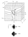
- FIG. 13A tomographic images T 1 to T n , an inner limiting membrane 1301, a retinal pigment epithelial layer 1302, and a papillary region 1303 are shown. Further, a projection area 1304 corresponding to the papillary area 1303 when the plane T ′ parallel to the xy plane and the tomographic images T 1 to T n are projected onto the plane T ′ and a partial area obtained by equally dividing the projection area 1304 DC 1 to DC 4 are shown respectively.
- the division number n 4.
- an irradiation angle at which the amount of signal light irradiated to the area becomes maximum is set.
- FIG. 13 (b) is a view of the plane T ′ of FIG. 13 (a) as viewed from the z-axis direction.
- the irradiation directions on the plane T ′ where the amount of signal light irradiated to the regions DC 1 to DC 4 is the largest are represented by D 1 to D 4 .
- the angle component ⁇ 1 the angle of ⁇ 1 corresponding to D 1 to D 4 is ⁇ 1 1 to ⁇ 1 4 (0 ° to Let the range of 360 ° be divided into four.
- the inclination of the irradiation angle of the signal light with respect to the surface of the retina is determined by the angle component theta 2, theta 2 is fixed at the maximum angle theta LIM physically alterable inclination relative to the retinal surface.
- the imaging instruction unit 1101 transmits the acquired instruction information 1 to the imaging unit 101.
- step S1207 the combining unit 1102 acquires the image data I 1 to I N of the tomograms from the storage unit 306, and generates image data obtained by combining them.
- the method of synthesis is as described above.
- the generated image data I C of the combined tomographic image is transmitted to the display unit 103.
- step S1208 the display unit 103 displays the image data I C obtained from the tomographic image synthesis unit 1192.
- the irradiation angle at which the signal light is irradiated most is set for each partial area of the optic nerve head, and the tomograms are acquired and combined to obtain the tissue of the recess. It is possible to present uniformly well-projected tomograms. Further, as in the first and second embodiments, it is possible to omit the image analysis processing that occurs after imaging a tomogram.
- the irradiation angle ⁇ MAX is determined, and based on this angle, the tomogram is re-imaged only once and displayed as it is.
- the number of re-imaging is not limited to one.
- an arrow may be added back from step S407 to step S402, and the process of steps S402 to S407 may be repeated until the evaluation value V in step S405 exceeds the threshold.
- the irradiation angle ⁇ MAX optimized by the re-imaging angle determination unit 305 is based on the image data of the tomographic image captured at that time, and the surface shape is accurate for the region where the image signal of the recessed portion is small. May not be extracted. In this case, since the angle ⁇ MAX is not determined based on the exact surface shape of the recess, the recess may not be sufficiently captured. On the other hand, imaging is performed again on the basis of the obtained irradiation angle ⁇ MAX , and a tomographic image in which a recessed portion is accurately captured is acquired, and then image evaluation and analysis are performed. As a result, it is possible to prevent the display of a tomographic image which is finally captured at an irradiation angle at which the depression is not sufficiently reflected.
- Examples 1 to 3 although an example in which the present invention is applied for the purpose of accurate shape extraction of the concavity of the optic disc is shown, the application of the present invention is not limited to this.
- the method of shape analysis, the method of calculating signal strength, etc. which are part of the features of the invention inherent in the present specification, can be applied to extracting the shape of the layer boundary. For example, it can also be applied to the extraction of layers or interfaces present in the area below the blood vessel which can not be imaged by the blood vessel.
- the OCT imaging apparatus that performs imaging based on the instruction of the information processing apparatus according to the present invention is not limited to the above. Although single-beam OCT is used in the present embodiment, multi-beam OCT may be used.
- the present invention supplies a program that implements the functions of the above-described embodiments to a system or apparatus via a network or various storage media, and a computer (or CPU etc.) of the system or apparatus reads and executes the program. It is also realized by In that case, the program supplied to the device or system or the storage medium storing the program constitutes the present invention.
- imaging unit 102 information processing apparatus 118 CPU 119 RAM 120 ROM 301 imaging instruction unit 302 tomographic image acquisition unit 303 shape analysis unit 304 re-imaging determination unit 305 re-imaging angle determination unit
Landscapes
- Physics & Mathematics (AREA)
- Health & Medical Sciences (AREA)
- Life Sciences & Earth Sciences (AREA)
- General Physics & Mathematics (AREA)
- General Health & Medical Sciences (AREA)
- Engineering & Computer Science (AREA)
- Biomedical Technology (AREA)
- Ophthalmology & Optometry (AREA)
- Veterinary Medicine (AREA)
- Public Health (AREA)
- Animal Behavior & Ethology (AREA)
- Nuclear Medicine, Radiotherapy & Molecular Imaging (AREA)
- Radiology & Medical Imaging (AREA)
- Surgery (AREA)
- Molecular Biology (AREA)
- Medical Informatics (AREA)
- Biophysics (AREA)
- Heart & Thoracic Surgery (AREA)
- Optics & Photonics (AREA)
- Biochemistry (AREA)
- Signal Processing (AREA)
- Automation & Control Theory (AREA)
- Chemical & Material Sciences (AREA)
- Pathology (AREA)
- Immunology (AREA)
- Analytical Chemistry (AREA)
- Eye Examination Apparatus (AREA)
Abstract
Description


ステップS401において、撮影指示部301は被検眼の眼底に対する2次元の計測範囲及び計測深度を調整する指示情報(以降、指示情報1と呼ぶ)を生成する。この指示情報1は、例えばマウス121を介したユーザの指定により行うが、記憶部306に格納された情報を用いても良い。また、撮影指示部301は、被検眼の瞳孔に対する信号光の入射位置を調整する指示情報(以降、指示情報2と呼ぶ)を生成する。この指示情報2は、被検眼の網膜に対する信号光の照射角度であるθPREを指示する情報である。撮影指示部301は、指示情報1及び指示情報2を撮像部101へと送信する。θPREについては特に限定されず、装置において予め定められた値を用いても、ユーザの指定により微調整ができるようにしてもよく、要は眼底の網膜に信号光が届けばよい。 <Step S401>
In step S401, the
ステップS402において、指示情報1及び2を受信することに応じて、撮像部101は撮影指示部301から取得した指示情報1及び指示情報2を撮像条件として断層像を撮像する。位置制御部115及び撮像部駆動機構116により、画像形成部104を移動させ、第一の照射角度θPREに応じた瞳孔上の位置に信号光を入射させる、撮像された断層像の画像データIと、事前照射角度θPREの値を記憶部306に格納する。 <Step S402>
In step S402, in response to receiving the
ステップS403において、形状解析部303は記憶部306に格納された断層像の画像データIを取得し、画像データIから視神経乳頭部の少なくとも一部の表面形状を抽出する。ここで少なくとも一部としているのは、全部の形状が特定されている必要がなく、また正確な形状や構造を特定することが本実施例における処理の目的だからである。視神経乳頭部は、網膜色素上皮層が存在しない部分における網膜の境界面(内境界膜)として抽出される。 <Step S403>
In step S403, the
ステップS404において再撮影判定部304は、形状解析部303から取得した画像データI及び形状データSに基づいて再撮影をすべきか否かを判定する。この判定は、陥凹部に照射された信号の強度が小さい領域の大きさまたは領域の有無に応じて行う。 <Step S404>
In step S404, the


ステップS405において、再撮影判定部304は、輝度評価値Vと一定の閾値VTHを比較し、断層像を表示するか否かを判定する。V<VTHの場合は、対象部位の所定位置への信号光の照射角度を再設定する命令(以降、命令情報2と呼ぶ)を再撮影角度決定部305に送信し、ステップS406に移る。V>=VTHの場合は、画像データI及び画像データIの表示を許可する情報(命令情報1と呼ぶ)を表示部103に送信し、ステップS407に移る。なお、画像信号の強度が小さい領域の大きさを評価値としても良い。この場合には、大きさの閾値を変えることにより再撮影するか否かの判定を行うこととなるため、再撮影に必要な時間と再撮影により得られる正確な画像情報とを比較衡量することができる。 <Step S405>
In step S405, the
ステップS406において、再撮影角度決定部305は、再撮影判定部304から命令情報2を取得した場合に、記憶部306からステップS402における断層像撮像時の事前照射角度θPREの値を取得する。そして、第一の照射角度である事前照射角度θPREと形状解析部303から取得した画像データI及び形状データSに応じて、撮影対象である陥凹部において、信号光の戻り光の強度が所望の強度となる第二の照射角度θMAXを取得する。そして、取得した照射角度θMAXから信号光の被検眼の瞳孔への入射位置PL:(xL,yL)を求め、指示情報3として撮像部101へと送信する。ここでは、信号光が照射されない(或いは照射された後に被験眼から得られる反射光の強度が極端に弱くなる)視神経乳頭部上の表面領域が最も少なくなる照射角度をθMAXとする。この処理については図7のフローチャートを用いて後述する。 <Step S406>
In step S406, when the re-imaging
ステップS407において、再撮影角度決定部305は、ステップS910で求めた照射角度θMAXを撮像パラメータに変換する。具体的には、ステップS402で述べた、網膜上の信号光が入射する点PL(xL,yL)から照射角度θ:(θ1,θ2)に変換する処理とは逆に、角度θから点PLに変換する。この変換は次の式(7)及び(8)により行うことができる。 <Step S407>
In step S407, the re-imaging

ステップS408において、撮像部101は、再撮影角度決定部305から取得した指示情報2を撮像パラメータとして、断層像を撮像し、断層像の画像データIを取得する。撮像方法は、ステップS402と同様である。なお、対象部位への信号光の照射角度を第一の照射角度θPREから第二の照射角度θMAXへと変更する手段として位置制御部115及び撮像部駆動機構116を用いて画像形成部104を移動させるが、これに限らない。例えば被検眼に提示する固視灯の位置を変更し、その位置に固視させて被検眼を回転させることにより、瞳孔への信号光の入射位置を変更させる手段を用いても良い。この場合には装置構成が単純になるというメリットがある。そして、取得した断層像の画像データI及び表示を許可する命令情報1を表示部103へと送信する。 <Step S408>
In step S408, the
ステップS409において表示部103は、再撮影判定部304または撮像部101から命令情報1を取得した場合に、同様に取得した画像データIを表示部103に表示する。 <Step S409>
When the
ステップS601において、再撮影角度決定部305は、記憶部306から事前照射角度θPREを取得し、基準照射方向D0を断層像の画像データI上に対応付ける。 <Step S601>
In step S601, the re-imaging
ステップS602において、再撮影角度決定部305は、照射角度の変更回数をNとし、変更する照射角度θ1~θNを、基準照射方向D0を基準として設定し、記憶部306に格納する。θの角度成分(θ1,θ2)は、 <Step S602>
In step S602, the re-imaging
ステップS603において、再撮影角度決定部305は、照射角度を変更する際の処理番号を <Step S603>
In step S603, the rephotographing
ステップS604において、再撮影角度決定部305は、記憶部306から照射角度θiを取得する。 <Step S604>
In step S604, the re-photographing
ステップS605において、再撮影角度決定部305は、照射角度θiに基づき、同様に取得した形状データSの勾配情報を解析し、形状データSの勾配マップGMΘiを生成する。この勾配マップは、照射される信号光の光束と陥凹部の各点における勾配のなす角度を表したものである。 <Step S605>
In step S605, re-imaging
ステップS606において、再撮影角度決定部305は、生成された勾配マップGMθiに基づき勾配評価値Giを算出する。この評価値は、陥凹部の各点における信号強度が所定の閾値以下である領域の大きさを示す。ステップS605にて得られた勾配の平均値が所定の閾値以下である領域の数を勾配評価値Giとする。または、各部分領域における勾配値の逆数が所定の閾値以上である領域において、その勾配値の逆数を全領域に渡って加算した値を評価値Giとしても良い。ここでいう所定の閾値は予め設定しておいても、ユーザにより指定してもよく、形状解析のアルゴリズムやユーザの要望等に合わせて変更される。 <Step S606>
In step S606, the re-photographing
ステップS607において、再撮影角度決定部305は、記憶部306に評価値の最大値GMAXが格納されていない場合は、GMAX=Giとして記憶部306に格納する。既に最大値GMAXが格納されている場合は、GMAXとGiの値を比較し、GMAX<GiならばGMAX=Giとして値を更新し、記憶部306に格納する。さらに、このときのGMAXに対応する照射角度θMAXをθMAX=θiとして値を更新し、記憶部306に格納する。 <Step S607>
In step S607, when the maximum value G MAX of the evaluation value is not stored in the
ステップS608において、再撮影角度決定部305は、処理番号iを1増加させる。 <Step S608>
In step S608, the re-photographing
ステップS609において、再撮影角度決定部305は、処理番号iと変更回数Nを比較し、i>NであればステップS608へ移行し、そうでなければステップS903へ移行する。 <Step S609>
In step S609, the re-photographing
ステップS608において、再撮影角度決定部305は、記憶部306から照射角度θMAXを取得する。このとき、θMAX={θM1,θM2}とする。そして、ステップS406の終了処理に移る。 <Step S610>
In step S608, the re-imaging
以下に、勾配評価値Giの変形例を示す。特に凹部が湾曲していない通常の陥凹部に対して好適なものである。この勾配評価値は、特に凹部が湾曲していない通常の陥凹部に対して好適なものである。凹部が湾曲していないとは、凹部の中心軸が略直線となっているものをいう。そのような場合には、凹部の中心軸と平行となる照射角度がθMAXとなる。また、凹部の中心軸に対して信号強度が等方性を有するという性質を利用している。図8は、湾曲等の複雑な形状を有しない陥凹部に対して適切な照射角度で照射した状態を示している。このような場合、内境界膜704の陥凹部に照射される信号光の強度が等方性を有し、勾配マップGMΘiは、マップ中心からリング状に等輝度の領域が広がるような輝度分布となる。この場合、領域GMR1~GMR4は、互いに似た輝度分布となる。 (Modification 1)
The following is a modification of the gradient evaluation value G i. In particular, it is suitable for ordinary depressions where the depressions are not curved. This gradient rating is particularly suitable for normal depressions in which the depressions are not curved. The fact that the recess is not curved means that the central axis of the recess is substantially straight. In such a case, the irradiation angle parallel to the central axis of the recess is θ MAX . Moreover, the property that signal intensity has isotropy with respect to the central axis of a recessed part is utilized. FIG. 8 shows a state in which the concave portion not having a complicated shape such as a curve is irradiated at an appropriate irradiation angle. In such a case, the intensity of the signal light irradiated to the depressions of the

第二の変形例では、第一の断層像にて信号強度が小さい領域に対して最も信号強度が大きくなるように第二の照射角度を求める。この場合には、第一の照射角度により得られた第一の断層像と第二の照射角度により得られた第二の断層像を表示部103に表示させることで陥凹部の形状を正確に確認することができる。また、後述する実施例3の構成を用い、断層像を合成してもよい。この場合には、より正確な形状を表した断層像を得ることができる。具体的には、上述のステップS606にて再撮影角度決定部305が算出する勾配評価値を、第一の照射角度θPREで撮影された断層像において形状が正確に特定できず補完した領域に対して最も光が照射される場合に高い評価とすればよい。 (Modification 2)
In the second modification, the second irradiation angle is determined so that the signal intensity is the largest in the region where the signal intensity is small in the first tomographic image. In this case, the shape of the recess is accurately determined by displaying on the
また、実施例1では、視神経乳頭の表面形状の勾配値が全体で等方化されるように信号光の照射角度を求めたが、表面形状の解析方法はこれに限らない。例えば、次の方法で表面形状を解析し、照射角度θMAXを求める。図7に基づいて説明する。実施例1の形状解析部303にて得られた陥凹部の形状データSから陥凹部の最深位置を検出する。この位置を点pDとする。次に、照射角度を擬似的に変更させたときの、形状マップの投影基準面T´における乳頭部領域703の対応領域を703’、点pDの対応点をpD’とする。このとき、点pD’がこの領域703’の重心に一致するような照射角度θをθMAXとして取得する。これにより、乳頭部領域に対して、陥凹の最深部分が中心に来るような照射角度を求めることができる。この方法により、より簡便な画像解析による照射角度の取得を行うことができる。 (Modification 3)
Moreover, in Example 1, although the irradiation angle of signal light was calculated | required so that the gradient value of the surface shape of an optic nerve tip may be isotropic in the whole, the analysis method of surface shape is not restricted to this. For example, the surface shape is analyzed by the following method to determine the irradiation angle θ MAX . This will be described based on FIG. The deepest position of the recessed portion is detected from the shape data S of the recessed portion obtained by the
ステップS1001において、撮影指示部901は指示情報1を生成する。そして照射角度の変更回数をNとし、変更する照射角度θ1~θNを設定し保持する。照射角度θ1~θNは、実施例1におけるステップS602と同様の方法で設定する。但し、ステップS602では、θ1~θNを、取り得る値の範囲において網羅的に設定したのに対し、ここでは、角度の変更間隔をより粗く設定してもよい。これは本実施例では、実施例1のように最適な照射角度を見つけるのではなく、概ね陥凹部の組織が画像化される断層像を取得することを目的とするためである。例えば、θの角度成分θ1に関しては分割数N1=4(0°~360°を4等分)、角度成分θ2に関しては分割数 <Step S1001>
In step S1001, the imaging instruction unit 901 generates
ステップS1002において、撮影指示部301は、照射角度を変更する際の処理番号を <Step S1002>
In step S1002, the photographing
ステップS1003において撮影指示部301は、照射角度θiを撮像パラメータに変換し、これを指示情報2として、撮像部101へと送信する。変換方法は、図4のステップS407と同様の方法で設定するため、説明は省略する。 <Step S1003>
ステップS1004において、撮像部101は、撮影指示部301から取得した指示情報1及び指示情報2を撮像パラメータとして断層像を撮像する。撮像方法は、ステップS402と同様であるため、説明は省略する。このとき、撮像した照射角度θiに対応する断層像の画像データをIiと定義する。断層像取得部302は撮像した画像データIiを撮像部101から取得し、記憶部306に格納する。 <Step S1004>
In step S1004, the
ステップS1005において、形状解析部303は、記憶部306に格納された画像データIiを取得し、画像データIiから視神経乳頭の表面形状を抽出する。抽出方法は、ステップS403と同様であるため、説明は省略する。このとき、抽出した表面形状データをSiと定義する。そして、画像データIi及び抽出した形状データSiを輝度情報解析部1305へと送信する。 <Step S1005>
In step S1005, the
ステップS1006において、選択部702は、形状解析部303から取得した画像データIi及び形状データSiに基づき輝度情報を解析し、輝度評価値Viを求める。Viの求め方は、ステップS404と同様であるため、説明は省略する。 <Step S1006>
In step S1006, the selection unit 702 analyzes the luminance information on the basis of the image data I i and the shape data S i obtained from the
ステップS1007において、選択部702は、記憶部306に格納された画像データIiに対応する輝度評価値Viを取得し、記憶部306に評価値の最大値VMAXが格納されていない場合は、VMAX=Viとして記憶部306に格納する。既に最大値VMAXが格納されている場合は、VMAXとViの値を比較し、VMAX<ViならばVMAX=Viとして値を更新し、記憶部306に格納する。さらに、このときのVMAXに対応する処理番号をnMAX=i、画像データをIMAX=Iiとして値を更新し、記憶部306に格納する。 <Step S1007>
In step S1007, the selection unit 702 obtains the luminance evaluation value V i corresponding to the image data I i stored in the
ステップS1008において、撮影指示部901は、処理番号iを1増加させる。 <Step S1008>
In step S1008, the photographing instruction unit 901 increments the processing number i by one.
ステップS1009において、撮影指示部901は、処理番号iと変更回数Nを比較し、i>Nであれば、記憶部306から画像データIMAXを取得し、表示部103へと送信した後、ステップS1010へ移行する。i≦Nであれば、ステップS1003へ移行する。 <Step S1009>
In step S1009, the imaging instruction unit 901 compares the processing number i with the number of changes N. If i> N, the image data I MAX is acquired from the
ステップS1010において、表示部103は、選択部702により選択された画像データIMAXを不図示のモニタに表示する。 <Step S1010>
In step S1010, the
ステップS1201において、撮像指示部1101は指示情報1を生成する。そして、照射角度の変更回数をNとし、変更する照射角度θ1~θNを設定し保持する。照射角度θ1~θNは、本実施例ではθ1は取り得る値の範囲で均等に分割するが、瞳孔の外延部から信号光を入射させるため、θ2の値はθ2=θLIMで固定にする。503、画像信号が非常に弱い領域504が示されている。 <Step S1201>
In step S1201, the imaging instruction unit 1101 generates
ステップS1207において、合成部1102は、記憶部306から断層像の画像データI1~INを取得し、それらを合成した画像データを生成する。合成の方法は先述のとおりである。そして、生成した合成断層像の画像データICを表示部103へ送信する。 <Step S1207>
In step S1207, the combining
ステップS1208において、表示部103は、断層像合成部1192から取得した画像データICを表示する。 <Step S1208>
In step S1208, the
第一実施例では、最初に取得した断層像の輝度評価値Vが閾値を満たさない場合に、照射角度θMAXを求め、この角度に基づき断層像を一回のみ再撮像してそのまま表示するが、再撮像の回数は一回に限らない。例えば、図4において、ステップS407からS402に戻る矢印を付け加え、ステップS405における評価値Vが閾値を超えるまでステップS402~S407の処理を繰り返す手順をとってもよい。これは、再撮影角度決定部305で最適化される照射角度θMAXは、そのとき撮像された断層像の画像データに基づくものであり、陥凹部の画像信号が小さい領域に関しては表面形状が正確に抽出されていない可能性がある。この場合、角度θMAXは、陥凹部の正確な表面形状に基づいて求められていないため、陥凹部が充分に写らない可能性がある。これに対して、得られた照射角度θMAXに基づいて再度撮像を行い、より陥凹部が正確に写った断層像を取得した上で、画像評価・解析を行う。これにより、最終的に陥凹部の写り方が不十分な照射角度で撮像された断層像を表示することを防ぐことができる。 (Other embodiments)
In the first embodiment, when the luminance evaluation value V of the tomogram acquired first does not satisfy the threshold, the irradiation angle θ MAX is determined, and based on this angle, the tomogram is re-imaged only once and displayed as it is. The number of re-imaging is not limited to one. For example, in FIG. 4, an arrow may be added back from step S407 to step S402, and the process of steps S402 to S407 may be repeated until the evaluation value V in step S405 exceeds the threshold. This is because the irradiation angle θ MAX optimized by the re-imaging
102 情報処理装置
118 CPU
119 RAM
120 ROM
301 撮像指示部
302 断層像取得部
303 形状解析部
304 再撮影判定部
305 再撮影角度決定部 101
119 RAM
120 ROM
301
Claims (17)
- 撮影対象の少なくとも一部の形状に応じて前記撮影対象に照射される信号光の戻り光が所定の強度となる前記信号光の照射角度を決定する決定手段と、
前記決定された照射角度で前記撮影対象に照射される信号光の戻り光に基づいて前記撮影対象の断層像を撮像する指示を行う指示手段と、
を有することを特徴とする情報処理装置。 Determining means for determining an irradiation angle of the signal light at which return light of the signal light irradiated to the object to be photographed has a predetermined intensity according to at least a part of the shape of the object to be photographed;
An instruction unit configured to instruct imaging of a tomogram of the imaging target based on return light of the signal light emitted to the imaging target at the determined irradiation angle;
An information processing apparatus comprising: - 前記決定手段は撮影対象の形状に応じて前記撮影対象に対して照射される信号光の強度が基準より弱い領域を小さくなるように前記信号光の照射角度を決定することを特徴とする請求項1に記載の情報処理装置。 The determination means determines the irradiation angle of the signal light so that the intensity of the signal light irradiated to the object to be photographed becomes smaller in a region weaker than a reference according to the shape of the object to be photographed. The information processing apparatus according to 1.
- 前記撮影対象に対して所定の角度から照射された信号光の戻り光に基づいて撮像された前記撮影対象の断層像を取得する取得手段を有し、
前記決定手段は前記取得された断層像に基づいて前記撮影対象の形状を決定することを特徴とする請求項1または2に記載の情報処理装置。 The acquiring unit further includes an acquiring unit configured to acquire a tomographic image of the imaging target, which is imaged based on the return light of the signal light irradiated from the predetermined angle to the imaging target.
The information processing apparatus according to claim 1, wherein the determination unit determines the shape of the imaging target based on the acquired tomographic image. - 前記所定の角度が前記決定された角度と同じになる場合には、前記指示手段による指示を行わないことを特徴とする請求項3に記載の情報処理装置。 The information processing apparatus according to claim 3, wherein the instruction by the instruction unit is not performed when the predetermined angle is the same as the determined angle.
- 前記取得された断層像において前記戻り光の強度が基準より弱い領域、前記撮影対象の形状を特定できなかった領域、前記撮影対象の形状を補間により推定した領域、または前記形状の信頼性が低い領域のいずれかの大きさに応じて前記指示手段による指示を行うか否かを判定する判定手段と、
を有することを特徴とする請求項3乃至4のいずれか1項に記載の情報処理装置。 In the acquired tomogram, the region where the intensity of the return light is weaker than the reference, the region where the shape of the object to be imaged can not be identified, the region where the shape of the object to be imaged is estimated by interpolation, or the reliability of the shape is low A determination unit that determines whether or not to perform an instruction by the instruction unit according to any size of the area;
The information processing apparatus according to any one of claims 3 to 4, characterized in that - 前記撮影対象は網膜の層の境界面であり、
前記決定手段は前記境界面の各領域に対する前記信号光の入射角に応じて前記信号光の強度を評価することを特徴とする請求項1乃至5のいずれか1項に記載の情報処理装置。 The subject is the boundary of the retina layer,
The information processing apparatus according to any one of claims 1 to 5, wherein the determination unit evaluates the intensity of the signal light in accordance with an incident angle of the signal light with respect to each area of the boundary surface. - 前記撮影対象は網膜の陥凹部であり、
前記決定手段は前記陥凹部の前記網膜の表面に対する傾きに応じて前記照射角度を決定することを特徴とする請求項1乃至6のいずれか1項に記載の情報処理装置。 The subject is a depression of the retina,
The information processing apparatus according to any one of claims 1 to 6, wherein the determination unit determines the irradiation angle according to an inclination of the recess with respect to the surface of the retina. - 前記指示手段は前記撮像をすべき旨の通知、撮像部への撮影条件の送信、または撮像の指示のいずれかを行うことを特徴とする請求項1乃至7のいずれか1項に記載の情報処理装置。 8. The information according to any one of claims 1 to 7, wherein the instruction means issues one of a notification that the imaging should be performed, transmission of imaging conditions to the imaging unit, and an instruction of imaging. Processing unit.
- 複数の異なる角度から撮影対象に照射する信号光の戻り光の夫々により複数の断層像を取得する取得手段と、
前記取得された断層像の夫々における、前記戻り光の強度が基準より弱い領域の大きさに応じて前記取得された断層像から少なくとも1つの断層像を選択する選択手段とを有することを特徴とする情報処理装置。 Acquisition means for acquiring a plurality of tomograms by each of the return light of the signal light to be applied to the imaging object from a plurality of different angles;
Selecting means for selecting at least one tomogram from the acquired tomograms according to the size of a region where the intensity of the return light is weaker than a reference in each of the acquired tomograms. Information processing device. - 前記選択手段は、前記断層像の輝度値またはS/N比に基づいて前記戻り光の強度を評価することを特徴とする請求項9に記載の情報処理装置。 10. The information processing apparatus according to claim 9, wherein the selection unit evaluates the intensity of the return light based on a luminance value or an S / N ratio of the tomographic image.
- 複数の異なる角度から撮影対象に照射する信号光の戻り光の夫々により複数の断層像を取得する取得手段と、
前記取得された断層像を合成する合成手段とを有することを特徴とする情報処理装置。 Acquisition means for acquiring a plurality of tomograms by each of the return light of the signal light to be applied to the imaging object from a plurality of different angles;
An information processing apparatus comprising: combining means for combining the acquired tomograms. - 前記撮影対象は網膜であり、前記複数の異なる角度は瞳孔の外延部から入射させることを特徴とする請求項9乃至11のいずれか1項に記載の情報処理装置。 The information processing apparatus according to any one of claims 9 to 11, wherein the imaging target is a retina, and the plurality of different angles are incident from an outer extension of a pupil.
- 前記断層像は、光源からの光を信号光と参照光とに分割し、前記信号光を撮影対象に導くと共に前記参照光を参照ミラーに導き、前記撮影対象によって反射あるいは散乱された前記信号光による戻り光と、前記参照ミラーによって反射された参照光とを用い、前記撮影対象の断層像を撮像するための光断層像撮像装置により撮影されることを特徴とする請求項1乃至12のいずれか1項に記載の情報処理装置。 The tomogram divides light from a light source into signal light and reference light, guides the signal light to a subject to be photographed and guides the reference light to a reference mirror, and the signal light reflected or scattered by the subject to be photographed The optical tomographic image capturing apparatus for capturing a tomographic image of the imaging target using the return light by the light source and the reference light reflected by the reference mirror, according to any one of claims 1 to 12, An information processing apparatus according to any one of the preceding items.
- 被検眼の網膜の陥凹部の形状を特定する特定手段と、
前記特定された陥凹部の形状に基づいて前記陥凹部に照射する信号光の戻り光が所定の強度となる前記陥凹部に照射する信号光の照射角度を決定する決定手段と、
前記決定された照射角度で照射した信号光の戻り光に基づいて干渉光を生成することにより前記陥凹部を撮像した断層像を取得する取得手段と
を有することを特徴とする情報処理装置。 Specifying means for specifying the shape of the depression of the retina of the subject eye;
Determining means for determining an irradiation angle of the signal light to be irradiated to the recess where the return light of the signal light to be irradiated to the recess is a predetermined intensity based on the shape of the specified recess.
An information processing apparatus comprising: an acquiring unit configured to acquire a tomographic image obtained by imaging the recessed portion by generating interference light based on the return light of the signal light irradiated at the determined irradiation angle. - 撮影対象の形状に応じて、前記撮影対象に照射される信号光の戻り光が所定の強度となる前記信号光の照射角度を決定するステップと、
前記決定された照射角度で前記撮影対象に照射される信号光の戻り光に基づいて前記撮影対象の断層像を撮像する指示を行うステップと
を有することを特徴とする情報処理方法。 Determining an irradiation angle of the signal light at which return light of the signal light irradiated to the object to be photographed has a predetermined intensity according to a shape of the object to be photographed;
An instruction to capture a tomogram of the imaging target based on the return light of the signal light emitted to the imaging target at the determined irradiation angle. - 撮影対象の形状に応じて前記撮影対象に照射される信号光の戻り光が所定の強度となる前記信号光の照射角度を決定する処理と、
前記決定された照射角度で前記撮影対象に照射される信号光の戻り光に基づいて前記撮影対象の断層像を撮像する指示を行う処理と
をコンピュータに実行させることを特徴とするプログラム。 A process of determining an irradiation angle of the signal light such that return light of the signal light irradiated to the object to be photographed has a predetermined intensity according to a shape of the object to be photographed;
A program for causing a computer to execute an instruction to capture a tomogram of the imaging target based on return light of the signal light emitted to the imaging target at the determined irradiation angle. - 撮影対象に所定の角度から照射する信号光の戻り光により前記撮影対象を撮像して断層像を得る撮像手段と、
前記撮像手段から撮影対象に第一の照射角度から照射した信号光の戻り光に基づき前記撮影対象の断層像を取得する取得手段と、
前記取得された断層像から前記撮影対象の形状を解析する解析手段と、
前記解析の結果に応じて前記撮影対象に前記第一の照射角度とは異なる第二の照射角度から前記信号光を照射して前記撮影対象を撮像する指示を前記撮像手段に対して指示手段と、
前記指示手段による指示に応じて撮像手段が撮像した断層像を表示させる表示手段と
を有することを特徴とする撮像システム。 Imaging means for imaging a to-be-photographed object by a return light of signal light irradiated to the to-be-photographed object from a predetermined angle to obtain a tomographic image
An acquisition unit configured to acquire a tomographic image of the imaging target based on return light of signal light emitted from the imaging unit to the imaging target from a first irradiation angle;
Analysis means for analyzing the shape of the imaging target from the acquired tomographic image;
An instruction unit for instructing the imaging unit to irradiate the signal light onto the object to be photographed from a second irradiation angle different from the first irradiation angle according to a result of the analysis and to image the object to be photographed; ,
An imaging system comprising: a display unit configured to display a tomographic image captured by an imaging unit according to an instruction from the instruction unit.
Priority Applications (6)
| Application Number | Priority Date | Filing Date | Title |
|---|---|---|---|
| JP2011538162A JP5528467B2 (en) | 2009-10-29 | 2009-10-29 | Imaging control apparatus, image processing apparatus, imaging control method, program, and imaging system |
| EP20090850841 EP2494916A4 (en) | 2009-10-29 | 2009-10-29 | Information processing device, method, system, and program |
| PCT/JP2009/068619 WO2011052062A1 (en) | 2009-10-29 | 2009-10-29 | Information processing device, method, system, and program |
| KR1020127012347A KR101496669B1 (en) | 2009-10-29 | 2009-10-29 | Information processing device, method, system, and recording medium |
| CN200980162266.3A CN102596004B (en) | 2009-10-29 | 2009-10-29 | Apparatus, method, and program for processing information |
| US12/911,331 US8696123B2 (en) | 2009-10-29 | 2010-10-25 | Apparatus, method, and program for processing information |
Applications Claiming Priority (1)
| Application Number | Priority Date | Filing Date | Title |
|---|---|---|---|
| PCT/JP2009/068619 WO2011052062A1 (en) | 2009-10-29 | 2009-10-29 | Information processing device, method, system, and program |
Publications (1)
| Publication Number | Publication Date |
|---|---|
| WO2011052062A1 true WO2011052062A1 (en) | 2011-05-05 |
Family
ID=43921503
Family Applications (1)
| Application Number | Title | Priority Date | Filing Date |
|---|---|---|---|
| PCT/JP2009/068619 WO2011052062A1 (en) | 2009-10-29 | 2009-10-29 | Information processing device, method, system, and program |
Country Status (6)
| Country | Link |
|---|---|
| US (1) | US8696123B2 (en) |
| EP (1) | EP2494916A4 (en) |
| JP (1) | JP5528467B2 (en) |
| KR (1) | KR101496669B1 (en) |
| CN (1) | CN102596004B (en) |
| WO (1) | WO2011052062A1 (en) |
Cited By (3)
| Publication number | Priority date | Publication date | Assignee | Title |
|---|---|---|---|---|
| JP2012161427A (en) * | 2011-02-04 | 2012-08-30 | Nidek Co Ltd | Ophthalmic photographing device |
| WO2015098912A1 (en) * | 2013-12-25 | 2015-07-02 | 興和株式会社 | Tomography device |
| WO2017135278A1 (en) * | 2016-02-02 | 2017-08-10 | 株式会社ニデック | Tomographic-image image pickup device |
Families Citing this family (14)
| Publication number | Priority date | Publication date | Assignee | Title |
|---|---|---|---|---|
| JP5921068B2 (en) * | 2010-03-02 | 2016-05-24 | キヤノン株式会社 | Image processing apparatus, control method, and optical coherence tomography system |
| JP5597011B2 (en) * | 2010-03-31 | 2014-10-01 | キヤノン株式会社 | Ophthalmic apparatus and control method thereof |
| JP5781351B2 (en) | 2011-03-30 | 2015-09-24 | 日本アビオニクス株式会社 | Imaging apparatus, pixel output level correction method thereof, infrared camera system, and interchangeable lens system |
| JP5383735B2 (en) * | 2011-03-31 | 2014-01-08 | キヤノン株式会社 | Optical coherence tomography apparatus, image processing apparatus, image processing method, and program |
| US9055892B2 (en) | 2011-04-27 | 2015-06-16 | Carl Zeiss Meditec, Inc. | Systems and methods for improved ophthalmic imaging |
| JP5778469B2 (en) * | 2011-04-28 | 2015-09-16 | 日本アビオニクス株式会社 | Imaging apparatus, image generation method, infrared camera system, and interchangeable lens system |
| JP5210442B1 (en) * | 2012-01-26 | 2013-06-12 | キヤノン株式会社 | Optical tomographic imaging apparatus and control method |
| US9955865B2 (en) * | 2013-04-11 | 2018-05-01 | Novartis Ag | Method and system to detect ophthalmic tissue structure and pathologies |
| US9819933B2 (en) * | 2013-10-18 | 2017-11-14 | Alcatel Lucent | Automated testing of media devices |
| KR101492343B1 (en) * | 2013-11-15 | 2015-02-11 | 한국과학기술원 | Apparatus for detecting light scattering pattern and method for detecting light scattering pattern |
| JP6499416B2 (en) * | 2014-10-10 | 2019-04-10 | キヤノン株式会社 | Ophthalmic apparatus and method for controlling ophthalmic apparatus |
| US10130250B2 (en) * | 2015-11-02 | 2018-11-20 | Nidek Co., Ltd. | OCT data processing apparatus and OCT data processing program |
| JP6680812B2 (en) * | 2018-01-30 | 2020-04-15 | ファナック株式会社 | Work image generator |
| JP7166184B2 (en) * | 2019-02-05 | 2022-11-07 | 株式会社トプコン | Ophthalmic information processing device, ophthalmic device, ophthalmic information processing method, and program |
Citations (4)
| Publication number | Priority date | Publication date | Assignee | Title |
|---|---|---|---|---|
| EP0910984A1 (en) * | 1997-09-24 | 1999-04-28 | Heidelberg Engineering Optische Messsysteme GmbH | Method and apparatus for determining optical characteristics of a cornea |
| JP2005506107A (en) * | 2001-03-15 | 2005-03-03 | ウェーブフロント・サイエンシーズ・インコーポレイテッド | Tomographic wavefront analysis system and method for mapping optical systems |
| JP2007501677A (en) * | 2003-05-22 | 2007-02-01 | カール ツアイス メディテック アクチエンゲゼルシャフト | Method and apparatus for anterior eye measurement |
| JP2008246158A (en) | 2007-03-30 | 2008-10-16 | Topcon Corp | Optical image measurement instrument, program controlling it, and optical image measurement method |
Family Cites Families (10)
| Publication number | Priority date | Publication date | Assignee | Title |
|---|---|---|---|---|
| GB2182164A (en) * | 1985-09-27 | 1987-05-07 | Keeler Ltd | Indirect ophthalmoscope |
| JP2618912B2 (en) * | 1987-08-31 | 1997-06-11 | 興和株式会社 | Fundus examination device |
| DE69533903T2 (en) * | 1994-08-18 | 2005-12-08 | Carl Zeiss Meditec Ag | Surgical apparatus controlled by optical coherence tomography |
| CN1089226C (en) * | 1997-04-04 | 2002-08-21 | 华南理工大学 | Retinal blood vessels caliber deformation intelligence detecting system and method |
| JP4439815B2 (en) * | 2002-08-22 | 2010-03-24 | 株式会社トプコン | Surgical microscope |
| JP4444194B2 (en) * | 2005-09-30 | 2010-03-31 | 株式会社トプコン | Ophthalmic microscope |
| US8072623B2 (en) * | 2007-02-16 | 2011-12-06 | Ricoh Company, Ltd. | Image processing apparatus, method for controlling image processing apparatus, control program, and recording medium |
| US8125645B2 (en) * | 2008-03-31 | 2012-02-28 | Fujifilm Corporation | Optical tomographic imaging system, tomographic image acquiring method, and optical tomographic image forming method |
| JP5478840B2 (en) * | 2008-05-19 | 2014-04-23 | キヤノン株式会社 | Optical tomographic imaging apparatus and control method for optical tomographic imaging apparatus |
| JP5268447B2 (en) * | 2008-06-26 | 2013-08-21 | キヤノン株式会社 | Medical imaging device |
-
2009
- 2009-10-29 JP JP2011538162A patent/JP5528467B2/en not_active Expired - Fee Related
- 2009-10-29 CN CN200980162266.3A patent/CN102596004B/en not_active Expired - Fee Related
- 2009-10-29 WO PCT/JP2009/068619 patent/WO2011052062A1/en active Application Filing
- 2009-10-29 EP EP20090850841 patent/EP2494916A4/en not_active Withdrawn
- 2009-10-29 KR KR1020127012347A patent/KR101496669B1/en active IP Right Grant
-
2010
- 2010-10-25 US US12/911,331 patent/US8696123B2/en not_active Expired - Fee Related
Patent Citations (4)
| Publication number | Priority date | Publication date | Assignee | Title |
|---|---|---|---|---|
| EP0910984A1 (en) * | 1997-09-24 | 1999-04-28 | Heidelberg Engineering Optische Messsysteme GmbH | Method and apparatus for determining optical characteristics of a cornea |
| JP2005506107A (en) * | 2001-03-15 | 2005-03-03 | ウェーブフロント・サイエンシーズ・インコーポレイテッド | Tomographic wavefront analysis system and method for mapping optical systems |
| JP2007501677A (en) * | 2003-05-22 | 2007-02-01 | カール ツアイス メディテック アクチエンゲゼルシャフト | Method and apparatus for anterior eye measurement |
| JP2008246158A (en) | 2007-03-30 | 2008-10-16 | Topcon Corp | Optical image measurement instrument, program controlling it, and optical image measurement method |
Non-Patent Citations (1)
| Title |
|---|
| See also references of EP2494916A4 * |
Cited By (5)
| Publication number | Priority date | Publication date | Assignee | Title |
|---|---|---|---|---|
| JP2012161427A (en) * | 2011-02-04 | 2012-08-30 | Nidek Co Ltd | Ophthalmic photographing device |
| WO2015098912A1 (en) * | 2013-12-25 | 2015-07-02 | 興和株式会社 | Tomography device |
| JPWO2015098912A1 (en) * | 2013-12-25 | 2017-03-23 | 興和株式会社 | Tomography system |
| WO2017135278A1 (en) * | 2016-02-02 | 2017-08-10 | 株式会社ニデック | Tomographic-image image pickup device |
| JPWO2017135278A1 (en) * | 2016-02-02 | 2018-11-29 | 株式会社ニデック | Tomographic imaging system |
Also Published As
| Publication number | Publication date |
|---|---|
| EP2494916A1 (en) | 2012-09-05 |
| JPWO2011052062A1 (en) | 2013-03-14 |
| US20110102742A1 (en) | 2011-05-05 |
| KR20120085806A (en) | 2012-08-01 |
| EP2494916A4 (en) | 2014-01-01 |
| US8696123B2 (en) | 2014-04-15 |
| CN102596004B (en) | 2014-12-31 |
| CN102596004A (en) | 2012-07-18 |
| JP5528467B2 (en) | 2014-06-25 |
| KR101496669B1 (en) | 2015-02-27 |
Similar Documents
| Publication | Publication Date | Title |
|---|---|---|
| WO2011052062A1 (en) | Information processing device, method, system, and program | |
| JP5867719B2 (en) | Optical image measuring device | |
| JP5916110B2 (en) | Image display device, image display method, and program | |
| US10561311B2 (en) | Ophthalmic imaging apparatus and ophthalmic information processing apparatus | |
| JP6463047B2 (en) | Ophthalmic device and method of operating an ophthalmic device | |
| JP6411728B2 (en) | Ophthalmic observation device | |
| JP6633468B2 (en) | Blood flow measurement device | |
| JP2009276327A (en) | Optical image measuring device | |
| JP6736734B2 (en) | Ophthalmic photographing device and ophthalmic information processing device | |
| WO2020158282A1 (en) | Ophthalmic information processing device, ophthalmic device, ophthalmic information processing method, and program | |
| JP6637743B2 (en) | Ophthalmic equipment | |
| JP7215862B2 (en) | OPHTHALMIC PHOTOGRAPHIC APPARATUS, CONTROL METHOD, PROGRAM, AND RECORDING MEDIUM THEREOF | |
| EP3459434B1 (en) | Ophthalmologic apparatus and method of controlling the same | |
| WO2021149430A1 (en) | Ophthalmic information processing device, ophthalmic device, ophthalmic information processing method, and program | |
| JP2022060588A (en) | Ophthalmologic apparatus and control method of ophthalmologic apparatus | |
| JP6503040B2 (en) | Ophthalmic observation device | |
| JP6021289B2 (en) | Blood flow information generation device, blood flow information generation method, and program | |
| JP7325675B2 (en) | ophthalmic imaging equipment | |
| JP7236832B2 (en) | OPHTHALMIC PHOTOGRAPHIC APPARATUS, CONTROL METHOD, PROGRAM, AND RECORDING MEDIUM THEREOF | |
| JP7335107B2 (en) | Ophthalmic information processing device, ophthalmic device, ophthalmic information processing method, and program | |
| JP6404431B2 (en) | Ophthalmic observation device | |
| JP2018023819A (en) | Ophthalmological observation device |
Legal Events
| Date | Code | Title | Description |
|---|---|---|---|
| WWE | Wipo information: entry into national phase |
Ref document number: 200980162266.3 Country of ref document: CN |
|
| 121 | Ep: the epo has been informed by wipo that ep was designated in this application |
Ref document number: 09850841 Country of ref document: EP Kind code of ref document: A1 |
|
| WWE | Wipo information: entry into national phase |
Ref document number: 2011538162 Country of ref document: JP |
|
| WWE | Wipo information: entry into national phase |
Ref document number: 2009850841 Country of ref document: EP |
|
| NENP | Non-entry into the national phase |
Ref country code: DE |
|
| ENP | Entry into the national phase |
Ref document number: 20127012347 Country of ref document: KR Kind code of ref document: A |