JP6463047B2 - Ophthalmic device and method of operating an ophthalmic device - Google Patents
Ophthalmic device and method of operating an ophthalmic device Download PDFInfo
- Publication number
- JP6463047B2 JP6463047B2 JP2014181341A JP2014181341A JP6463047B2 JP 6463047 B2 JP6463047 B2 JP 6463047B2 JP 2014181341 A JP2014181341 A JP 2014181341A JP 2014181341 A JP2014181341 A JP 2014181341A JP 6463047 B2 JP6463047 B2 JP 6463047B2
- Authority
- JP
- Japan
- Prior art keywords
- image
- magnification
- images
- eye
- imaging
- Prior art date
- Legal status (The legal status is an assumption and is not a legal conclusion. Google has not performed a legal analysis and makes no representation as to the accuracy of the status listed.)
- Active
Links
Images


Classifications
-
- A—HUMAN NECESSITIES
- A61—MEDICAL OR VETERINARY SCIENCE; HYGIENE
- A61B—DIAGNOSIS; SURGERY; IDENTIFICATION
- A61B3/00—Apparatus for testing the eyes; Instruments for examining the eyes
- A61B3/0016—Operational features thereof
- A61B3/0025—Operational features thereof characterised by electronic signal processing, e.g. eye models
-
- A—HUMAN NECESSITIES
- A61—MEDICAL OR VETERINARY SCIENCE; HYGIENE
- A61B—DIAGNOSIS; SURGERY; IDENTIFICATION
- A61B3/00—Apparatus for testing the eyes; Instruments for examining the eyes
- A61B3/0016—Operational features thereof
- A61B3/0041—Operational features thereof characterised by display arrangements
-
- A—HUMAN NECESSITIES
- A61—MEDICAL OR VETERINARY SCIENCE; HYGIENE
- A61B—DIAGNOSIS; SURGERY; IDENTIFICATION
- A61B3/00—Apparatus for testing the eyes; Instruments for examining the eyes
- A61B3/0091—Fixation targets for viewing direction
-
- A—HUMAN NECESSITIES
- A61—MEDICAL OR VETERINARY SCIENCE; HYGIENE
- A61B—DIAGNOSIS; SURGERY; IDENTIFICATION
- A61B3/00—Apparatus for testing the eyes; Instruments for examining the eyes
- A61B3/10—Objective types, i.e. instruments for examining the eyes independent of the patients' perceptions or reactions
- A61B3/1015—Objective types, i.e. instruments for examining the eyes independent of the patients' perceptions or reactions for wavefront analysis
-
- A—HUMAN NECESSITIES
- A61—MEDICAL OR VETERINARY SCIENCE; HYGIENE
- A61B—DIAGNOSIS; SURGERY; IDENTIFICATION
- A61B3/00—Apparatus for testing the eyes; Instruments for examining the eyes
- A61B3/10—Objective types, i.e. instruments for examining the eyes independent of the patients' perceptions or reactions
- A61B3/1025—Objective types, i.e. instruments for examining the eyes independent of the patients' perceptions or reactions for confocal scanning
-
- A—HUMAN NECESSITIES
- A61—MEDICAL OR VETERINARY SCIENCE; HYGIENE
- A61B—DIAGNOSIS; SURGERY; IDENTIFICATION
- A61B3/00—Apparatus for testing the eyes; Instruments for examining the eyes
- A61B3/10—Objective types, i.e. instruments for examining the eyes independent of the patients' perceptions or reactions
- A61B3/12—Objective types, i.e. instruments for examining the eyes independent of the patients' perceptions or reactions for looking at the eye fundus, e.g. ophthalmoscopes
- A61B3/1241—Objective types, i.e. instruments for examining the eyes independent of the patients' perceptions or reactions for looking at the eye fundus, e.g. ophthalmoscopes specially adapted for observation of ocular blood flow, e.g. by fluorescein angiography
-
- A—HUMAN NECESSITIES
- A61—MEDICAL OR VETERINARY SCIENCE; HYGIENE
- A61B—DIAGNOSIS; SURGERY; IDENTIFICATION
- A61B3/00—Apparatus for testing the eyes; Instruments for examining the eyes
- A61B3/10—Objective types, i.e. instruments for examining the eyes independent of the patients' perceptions or reactions
- A61B3/14—Arrangements specially adapted for eye photography
-
- A—HUMAN NECESSITIES
- A61—MEDICAL OR VETERINARY SCIENCE; HYGIENE
- A61B—DIAGNOSIS; SURGERY; IDENTIFICATION
- A61B3/00—Apparatus for testing the eyes; Instruments for examining the eyes
- A61B3/10—Objective types, i.e. instruments for examining the eyes independent of the patients' perceptions or reactions
- A61B3/12—Objective types, i.e. instruments for examining the eyes independent of the patients' perceptions or reactions for looking at the eye fundus, e.g. ophthalmoscopes
- A61B3/1225—Objective types, i.e. instruments for examining the eyes independent of the patients' perceptions or reactions for looking at the eye fundus, e.g. ophthalmoscopes using coherent radiation
- A61B3/1233—Objective types, i.e. instruments for examining the eyes independent of the patients' perceptions or reactions for looking at the eye fundus, e.g. ophthalmoscopes using coherent radiation for measuring blood flow, e.g. at the retina
Description
本発明は眼科診療に用いられる眼科装置及び眼科装置の作動方法に関する。 The present invention relates to an ophthalmic apparatus used for ophthalmic medical care and an operating method of the ophthalmic apparatus.
生活習慣病や失明原因の上位を占める疾病の早期診療を目的として、眼部の検査が広く行われている。共焦点レーザー顕微鏡の原理を利用した眼科装置である走査型レーザー検眼鏡(SLO;Scanning Laser Ophthalmoscope)は、測定光であるレーザーを眼底に対してラスター走査し、その戻り光の強度から平面画像を高分解能かつ高速に得る装置である。以下、このような平面画像を撮像する装置をSLO装置、該平面画像をSLO画像と記す。 Eye examinations are widely performed for the purpose of early medical treatment of lifestyle-related diseases and diseases that account for the top causes of blindness. A scanning laser opthalmoscope (SLO), which is an ophthalmologic apparatus that uses the principle of a confocal laser microscope, performs a raster scan of the laser, which is the measurement light, on the fundus and obtains a planar image from the intensity of the return light. It is a device that obtains high resolution and high speed. Hereinafter, an apparatus that captures such a planar image is referred to as an SLO apparatus, and the planar image is referred to as an SLO image.
近年、SLO装置において測定光のビーム径を大きくすることにより、横分解能を向上させた網膜のSLO画像を取得することが可能になってきた。しかし、測定光のビーム径の大径化に伴い、網膜のSLO画像の取得において、被検眼の収差によるSLO画像のS/N比及び分解能の低下が問題になってきた。それを解決するために、被検眼の収差を波面センサでリアルタイムに測定し、被検眼にて発生する測定光やその戻り光の収差を波面補正デバイスで補正する補償光学系を有する補償光学SLO装置が開発され、高横分解能なSLO画像(高倍率画像)の取得を可能にしている。 In recent years, it has become possible to acquire an SLO image of the retina with improved lateral resolution by increasing the beam diameter of measurement light in an SLO apparatus. However, with the increase in the diameter of the measurement light beam, the acquisition of the SLO image of the retina has caused problems in the S / N ratio and resolution of the SLO image due to the aberration of the eye to be examined. In order to solve this problem, an adaptive optics SLO apparatus having an adaptive optical system that measures aberrations of the eye to be examined in real time with a wavefront sensor and corrects aberrations of measurement light generated in the eye to be examined and its return light with a wavefront correction device. Has been developed to enable acquisition of SLO images (high magnification images) with high lateral resolution.
このような高倍率画像は、動画像として取得することができ、血流動態を非侵襲に観察する目的等に利用される。このとき、各フレームから網膜血管を抽出した上で毛細血管における血球の移動速度等が計測される。また、高倍率画像を用いて視機能との関連を評価するために視細胞Pを検出した上で視細胞Pの密度分布や配列の計測が行われている。図6(b)に高倍率画像の例を示す。視細胞Pや毛細血管の位置に対応した低輝度領域Q、白血球の位置に対応した高輝度領域Wが観察できる。 Such a high-magnification image can be acquired as a moving image, and is used for the purpose of non-invasively observing blood flow dynamics. At this time, after extracting the retinal blood vessel from each frame, the moving speed of the blood cell in the capillary is measured. Further, in order to evaluate the relationship with the visual function using a high-magnification image, the density distribution and arrangement of the photoreceptor cells P are measured after the photoreceptor cells P are detected. FIG. 6B shows an example of a high magnification image. A low luminance region Q corresponding to the position of the photoreceptor cell P or capillary vessel, and a high luminance region W corresponding to the position of the white blood cell can be observed.
ここで、高倍率画像を用いて視細胞Pを観察する場合や視細胞Pの分布を計測する場合には、フォーカス位置を網膜外層(図6(a)のB5)付近に設定し、図6(b)のような高倍率画像を撮影する。一方、網膜内層(図6(a)のB2からB4)には網膜血管や分岐した毛細血管が走行している。このとき、患眼を撮影する場合には、その撮像対象領域が高倍率画像の画角よりも大きい場合がしばしば見られる。これは、広範な視細胞欠損領域を撮像する場合や、初期の毛細血管病変の好発部位である傍中心窩領域を撮像する場合等である。そこで、異なる撮影位置で撮影して得た複数の高倍率画像を貼り合わせて表示する技術が、特許文献1に開示されている。
Here, when observing the photoreceptor cells P using a high-magnification image or measuring the distribution of photoreceptor cells P, the focus position is set near the outer retina (B5 in FIG. 6A). A high-magnification image as shown in (b) is taken. On the other hand, retinal blood vessels and branched capillaries run in the inner retina (B2 to B4 in FIG. 6A). At this time, when photographing the affected eye, there are often cases where the imaging target area is larger than the angle of view of the high-magnification image. This is the case where a wide photoreceptor cell defect region is imaged, the parafoveal region which is a common site of early capillary lesions, or the like. Therefore,
また、ある撮影位置の高倍率の動画像における固視微動等の影響が大きな例外フレームを判定し、高倍率の動画像における判定された例外フレーム以外のフレームを表示する技術が、特許文献2に開示されている。 Patent Document 2 discloses a technique for determining an exceptional frame that has a large influence of fixation micromotion or the like in a high-magnification moving image at a certain shooting position and displaying frames other than the determined exceptional frame in the high-magnification moving image. It is disclosed.
ここで、異なる撮影位置で撮影して得た複数の高倍率の動画像それぞれの動画像から、代表画像を取得して張り合わせて表示する場合を考える。このとき、一般的には、複数の高倍率の動画像それぞれから代表画像を取得し、取得された代表画像を張り合わせることによって、広範囲の画像が生成される。この場合、取得された代表画像のうち隣接する撮影位置の代表画像同士を比較した場合、撮影位置や輝度特性、画像特徴等に関して、代表画像同士の連続性が良くないことがあった。このような広範囲の画像を用いて広範囲に分布する細胞群や組織、及びそれらの病変(視細胞欠損や毛細血管瘤)の分布を計測すると、解析不能な領域が発生する場合や解析対象が抽出できない場合等があった。 Here, consider a case in which representative images are acquired from the moving images of a plurality of high-magnification moving images obtained by shooting at different shooting positions and displayed together. At this time, generally, a representative image is acquired from each of a plurality of high-magnification moving images, and a wide range of images is generated by pasting the acquired representative images together. In this case, when the representative images at the adjacent photographing positions among the obtained representative images are compared, the continuity between the representative images may not be good with respect to the photographing position, luminance characteristics, image characteristics, and the like. Using such a wide range of images, measuring the distribution of a wide range of cell groups and tissues and their lesions (photocell defects and capillary aneurysms) can result in cases where unanalyzable areas occur and the analysis target is extracted. There were cases where it was not possible.
本発明の目的の一つは、異なる撮影位置で撮影して得た複数の高倍率画像の連続性が良くなるような撮影条件に基づいて眼部を撮影することである。 One of the objects of the present invention is to photograph the eye based on photographing conditions that improve the continuity of a plurality of high-magnification images obtained by photographing at different photographing positions.
本発明に係る眼科装置の一つは、
異なる時間に眼部の異なる位置で撮影して得た複数の高倍率画像の特性の連続性を示す情報が所定の条件を満たすように、前記眼部の少なくとも1つの位置で再撮影する撮影条件を決定する決定手段と、
前記決定された撮影条件に基づいて、前記眼部の少なくとも1つの位置で再撮影されるように、前記眼部を撮影するための眼科装置を制御する制御手段と、
前記複数の高倍率画像の少なくとも1つと前記再撮影して得た少なくとも1つの高倍率画像とを用いて、広範囲の画像を生成する画像生成手段と、を備える。
One of the ophthalmic devices according to the present invention is
As information indicating the continuity of the characteristics of a plurality of high magnification images images obtained by photographing at different locations eye at different times satisfies a predetermined condition, imaging of re-imaging at least one position of the eye A determination means for determining a condition;
Control means for controlling an ophthalmologic apparatus for photographing the eye part so as to be re- photographed at at least one position of the eye part based on the determined photographing condition;
Image generation means for generating a wide range of images using at least one of the plurality of high-magnification images and at least one high-magnification image obtained by re-imaging .
また、本発明に係る眼科装置の一つは、
異なる時間に眼部の異なる位置で撮影して得た複数の高倍率画像の画像群としての適合度を示す情報に基づいて、前記眼部を撮影するための眼科装置が再撮影する撮影条件を決定する決定手段と、
前記決定された撮影条件に基づいて、前記眼部の少なくとも1つの位置で再撮影されるように、前記眼科装置を制御する制御手段と、
前記複数の高倍率画像の少なくとも1つと前記再撮影して得た少なくとも1つの高倍率画像とを用いて、広範囲の画像を生成する画像生成手段と、を備える。
One of the ophthalmologic apparatuses according to the present invention is
Imaging conditions different time based on the information indicating the matching degree of the image group of the plurality of high magnification images images obtained by photographing at different locations eye in ophthalmic devices recaptured for photographing the eye A determination means for determining
Based on the determined imaging conditions, as recaptured at least one position of the eye, and a control means for controlling the ophthalmologic apparatus,
Image generation means for generating a wide range of images using at least one of the plurality of high-magnification images and at least one high-magnification image obtained by re-imaging .
また、本発明に係る眼科装置の作動方法の一つは、
異なる時間に眼部の異なる位置で撮影して得た複数の高倍率画像の特性の連続性を示す情報が所定の条件を満たすように、前記眼部の少なくとも1つの位置で再撮影する撮影条件を決定する工程と、
前記決定された撮影条件に基づいて、前記眼部の少なくとも1つの位置で再撮影されるように、前記眼部を撮影するための眼科装置を制御する工程と、
前記複数の高倍率画像の少なくとも1つと前記再撮影して得た少なくとも1つの高倍率画像とを用いて、広範囲の画像を生成する工程と、を有する。
One of the operating methods of the ophthalmic apparatus according to the present invention is as follows:
As information indicating the continuity of the characteristics of a plurality of high magnification images images obtained by photographing at different locations eye at different times satisfies a predetermined condition, imaging of re-imaging at least one position of the eye Determining the conditions;
Controlling an ophthalmologic apparatus for imaging the eye so that the image is re- imaged at at least one position of the eye based on the determined imaging conditions;
Generating a wide range image using at least one of the plurality of high magnification images and at least one high magnification image obtained by the re-photographing .
また、本発明に係る眼科装置の作動方法の一つは、
異なる時間に眼部の異なる位置で撮影して得た複数の高倍率画像の画像群としての適合度を示す情報に基づいて、前記眼部を撮影するための眼科装置が再撮影する撮影条件を決定する工程と、
前記決定された撮影条件に基づいて、前記眼部の少なくとも1つの位置で再撮影されるように、前記眼科装置を制御する工程と、
前記複数の高倍率画像の少なくとも1つと前記再撮影して得た少なくとも1つの高倍率画像とを用いて、広範囲の画像を生成する工程と、を有する。
One of the operating methods of the ophthalmic apparatus according to the present invention is as follows:
Imaging conditions different time based on the information indicating the matching degree of the image group of the plurality of high magnification images images obtained by photographing at different locations eye in ophthalmic devices recaptured for photographing the eye A step of determining
Based on the determined imaging conditions, as recaptured at least one position of the eye, and controlling the ophthalmologic apparatus,
Generating a wide range image using at least one of the plurality of high magnification images and at least one high magnification image obtained by the re-photographing .
本発明によれば、異なる撮影位置で撮影して得た複数の高倍率画像の連続性が良くなるような撮影条件に基づいて眼部を撮影することができる。 According to the present invention, it is possible to photograph the eye part based on photographing conditions that improve the continuity of a plurality of high-magnification images obtained by photographing at different photographing positions.
本実施形態に係る眼科装置は、眼部の異なる位置で撮影された複数の画像(画像群)の特性の連続性に基づいて、眼部の異なる位置で撮影する撮影条件を決定する決定手段(例えば、図1の指示部134)を備える。これにより、異なる撮影位置で撮影して得た複数の高倍率画像の連続性が良くなるような撮影条件に基づいて眼部を撮影することができる。 The ophthalmologic apparatus according to the present embodiment determines a shooting condition for shooting at different positions of the eye based on the continuity of characteristics of a plurality of images (image groups) shot at different positions of the eye. For example, the instruction unit 134) of FIG. Thereby, the eye part can be photographed based on photographing conditions that improve the continuity of a plurality of high-magnification images obtained by photographing at different photographing positions.
ここで、複数の画像(画像群)の特性とは、例えば、複数の画像の相対位置と輝度特性と画像特徴とのうち少なくとも一つのことである。また、撮影条件は、例えば、撮影位置(走査位置)、撮影画角(走査範囲)、光源の発光量、光検出器のゲイン、フレームレート等である。また、複数の画像(画像群)のそれぞれの画像は、動画像から取得される代表画像であり、動画像から選択された1枚の画像でも良いし、ノイズやアーチファクト等が比較的少ない複数枚の画像が選択され、選択された画像が重ね合わされた画像でも良い。 Here, the characteristic of the plurality of images (image group) is, for example, at least one of a relative position, a luminance characteristic, and an image feature of the plurality of images. The shooting conditions include, for example, a shooting position (scanning position), a shooting angle of view (scanning range), a light emission amount of a light source, a gain of a photodetector, a frame rate, and the like. In addition, each of the plurality of images (image group) is a representative image acquired from the moving image, and may be one image selected from the moving image, or a plurality of images with relatively little noise and artifacts. These images may be selected, and the selected images may be superimposed.
また、連続性を示す値を判定する判定手段を更に備えることが好ましく、これにより、判定された値が所定の条件を満たすように撮影条件を決定することができる。なお、判定された値が所定の条件を満たす場合とは、例えば、判定された値が閾値を超える場合や最大となる場合である。例えば、輝度特性を用いて連続性を判定する場合には、複数の画像の輝度値の差分が閾値以下になるような画像が取得されるように、撮影条件を決定することが好ましい。また、連続性を示す値は、複数の画像が張り合わせられた張り合わせ画像を用いて判定されることが好ましい。例えば、張り合わせ画像の数と面積と無血管領域境界の長さとのうち少なくとも一つに基づいて判定されるが、これらについては各実施形態で詳述する。以下、添付図面に従って本発明に係る眼科装置及びその作動方法の好ましい実施形態について詳説する。ただし本発明はこれに限定されるものではない。 In addition, it is preferable to further include a determination unit that determines a value indicating continuity, whereby the shooting condition can be determined so that the determined value satisfies a predetermined condition. The case where the determined value satisfies the predetermined condition is, for example, a case where the determined value exceeds a threshold value or a maximum value. For example, when the continuity is determined using the luminance characteristic, it is preferable to determine the shooting conditions so that an image in which the difference between the luminance values of a plurality of images is equal to or less than a threshold value is acquired. Moreover, it is preferable that the value indicating continuity is determined using a bonded image in which a plurality of images are bonded. For example, the determination is based on at least one of the number and area of the stitched images and the length of the avascular region boundary, which will be described in detail in each embodiment. Hereinafter, preferred embodiments of an ophthalmologic apparatus and an operating method thereof according to the present invention will be described in detail with reference to the accompanying drawings. However, the present invention is not limited to this.
[第1の実施形態:異なる位置の複数の画像の相対位置や輝度特性の連続性]
本実施形態に係る眼科装置は、異なる位置の複数の画像(画像群)の相対位置と輝度特性とのうち少なくとも一つの連続性に基づいて、画像群の適合度を判定する。該適合度が所定の値に満たない場合には適合しない画像について再撮像を指示することで、撮影範囲を略同一条件で観察できるように構成したものである。
[First embodiment: Continuity of relative positions and luminance characteristics of a plurality of images at different positions]
The ophthalmologic apparatus according to the present embodiment determines the suitability of an image group based on at least one continuity among relative positions and luminance characteristics of a plurality of images (image groups) at different positions. When the degree of matching is less than a predetermined value, the imaging range is configured to be observed under substantially the same conditions by instructing re-imaging for an image that does not match.
具体的には、図6(g)に示すような合計9枚の高倍率画像で画像群が構成され、画像群を構成する画像数に対する観察不能領域が属する画像の数を用いて画像群としての適合度を判定する場合について説明する。 Specifically, an image group is composed of a total of nine high-magnification images as shown in FIG. 6 (g), and the number of images to which the unobservable area belongs with respect to the number of images constituting the image group is used as an image group. A case of determining the degree of fitness of will be described.
(全体構成)
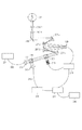
図2(a)は本実施形態に係る眼科装置10を含むシステムの構成図である。図2(a)に示すように眼科装置10は、SLO像撮像装置20やデータサーバ40と、光ファイバ、USBやIEEE1394等で構成されるローカル・エリア・ネットワーク(LAN)30を介して接続されている。なおこれらの機器との接続は、インターネット等の外部ネットワークを介して接続される構成であってもよいし、あるいは眼科装置10がSLO像撮像装置20に直接接続されている構成であってもよい。
(overall structure)
FIG. 2A is a configuration diagram of a system including the
まず、SLO像撮像装置20は眼部の広画角画像Dlや高倍率画像Dhを撮像する装置であり、前記広画角画像Dlや前記高倍率画像Dh、及びその撮影時に用いた固視標位置Fl、Fhの情報を眼科装置10及びデータサーバ40へ送信する。なお、各倍率の画像を異なる撮影位置で取得する場合にはDli,Dhjのように表す。すなわちi,jは各々撮影位置番号を示す変数であり、i=1,2,...,imax、j=1,2,...,jmaxとする。また、高倍率画像を異なる倍率で取得する場合には、最も倍率の高い画像から順にD1j,D2k,...のように表記し、D1jのことを高倍率画像、D2k,...を中間倍率画像と表記する。
First, the SLO
また、データサーバ40は、被検眼の広画角画像Dlや高倍率画像Dh、及びその撮影時に用いた固視標位置Fl、Fhのような撮像条件データ、眼部の画像特徴、眼部の画像特徴の分布に関する正常値などを保持する。眼部の画像特徴として、本発明では視細胞Pや毛細血管Q、血球W、網膜血管や網膜層境界に関する画像特徴を扱う。SLO像撮像装置20が出力する前記広画角画像Dl、前記高倍率画像Dh、撮影時に用いた固視標位置Fl、Fh、眼科装置10が出力する眼部の画像特徴を該サーバに保存する。また眼科装置10からの要求に応じ、広画角画像Dl、高倍率画像Dh、眼部の画像特徴及び該画像特徴の正常値データを眼科装置10に送信する。
The
次に、図1を用いて本実施形態に係る眼科装置10の機能構成を説明する。図1は、眼科装置10の機能構成を示すブロック図であり、眼科装置10はデータ取得部110、記憶部120、画像処理部130、指示取得部140を有する。また、データ取得部110は、画像取得部111を備える。画像処理部130は位置合わせ部131、個別画像判定部132、画像群判定部133、指示部134、表示制御部135を備える。さらに、指示部134は再撮像要否指示部1341を有する。
Next, the functional configuration of the
(補償光学系を備えたSLO像撮像装置)
次に、図3を用いて補償光学系を備えたSLO像撮像装置20の構成を説明する。まず、201は光源であり、SLD光源(Super Luminescent Diode)を用いた。本実施例では眼底撮像と波面測定のための光源を共用しているが、それぞれを別光源とし、途中で合波する構成としても良い。光源201から照射された光は、単一モード光ファイバー202を通って、コリメータ203により、平行な測定光205として照射される。照射された測定光205はビームスプリッタからなる光分割部204を透過し、補償光学の光学系に導光される。
(SLO imaging device with adaptive optics)
Next, the configuration of the SLO
補償光学系は、光分割部206、波面センサー215、波面補正デバイス208および、それらに導光するための反射ミラー207−1〜4から構成される。ここで、反射ミラー207−1〜4は、少なくとも眼の瞳と波面センサー215、波面補正デバイス208とが光学的に共役関係になるように設置されている。また、光分割部206として、本実施例ではビームスプリッタを用いる。また、本実施例では波面補正デバイス208として液晶素子を用いた空間位相変調器を用いる。なお、波面補正デバイスとして可変形状ミラーを用いる構成としてもよい。補償光学系を通過した光は、走査光学系209によって、1次元もしくは2次元に走査される。走査光学系209として、本実施形態では主走査用(眼底水平方向)と副走査用(眼底垂直方向)に2つのガルバノスキャナーを用いた。より高速な撮影のために、走査光学系209の主走査側に共振スキャナーを用いてもよい。走査光学系209で走査された測定光205は、接眼レンズ210−1および210−2を通して眼211に照射される。眼211に照射された測定光205は眼底で反射もしくは散乱される。接眼レンズ210−1および210−2の位置を調整することによって、眼211の視度にあわせて最適な照射を行うことが可能となる。ここでは、接眼部にレンズを用いたが、球面ミラー等で構成しても良い。
The compensation optical system includes a
眼211の網膜から反射もしくは散乱された反射散乱光(戻り光)は、入射した時と同様の経路を逆向きに進行し、光分割部206によって一部は波面センサー215に反射され、光線の波面を測定するために用いられる。波面センサー215は、補償光学制御部216に接続され、受光した波面を補償光学制御部216に伝える。波面補正デバイス208も補償光学制御部216に接続されており、補償光学制御部216から指示された変調を行う。補償光学制御部216は波面センサー215の測定結果による取得された波面を基に収差のない波面へと補正するような変調量(補正量)を計算し、波面補正デバイス208にそのように変調するように指令する。なお、波面の測定と波面補正デバイス308への指示は繰り返し処理され、常に最適な波面となるようにフィードバック制御が行われる。
The reflected scattered light (returned light) reflected or scattered from the retina of the
光分割部206を透過した反射散乱光は光分割部204によって一部が反射され、コリメータ212、光ファイバー213を通して光強度センサー214に導光される。光強度センサー214で光は電気信号に変換され、制御部217によって眼部画像として画像に構成されて、ディスプレイ218に表示される。なお、図3の構成で走査光学系の振り角を大きくし、補償光学制御部216が収差補正を行わないよう指示することによってSLO像撮像装置20は通常のSLO装置としても動作し、広画角なSLO画像(広画角画像Dl)を撮像できる。
A part of the reflected and scattered light transmitted through the
(眼科装置10のハードウェア構成及び実行手順)
次に、図4を用いて眼科装置10のハードウェア構成について説明する。図4において、301は中央演算処理装置(CPU)、302はメモリ(RAM)、303は制御メモリ(ROM)、304は外部記憶装置、305はモニタ、306はキーボード、307はマウス、308はインターフェースである。本実施形態に係る画像処理機能を実現するための制御プログラムや、当該制御プログラムが実行される際に用いられるデータは、外部記憶装置304に記憶されている。これらの制御プログラムやデータは、CPU301による制御のもと、バス309を通じて適宜RAM302に取り込まれ、CPU301によって実行され、以下に説明する各部として機能する。眼科装置10を構成する各ブロックの機能については、図5のフローチャートに示す眼科装置10の具体的な実行手順と関連付けて説明する。
(Hardware configuration and execution procedure of the ophthalmologic apparatus 10)
Next, the hardware configuration of the
<ステップ510:画像取得パターン選択>
眼科装置10は指示取得部140を通じて、ユーザが選択した所定の画像取得パターン(撮影位置や画角等)に関する情報を取得する。本実施形態では、黄斑部の中心窩に固視標位置Fl及びFhを設定して広画角画像Dlと図6(h)に示すような高倍率画像Dhjを取得する。なお撮影位置の設定方法はこれに限定されず、任意の位置に設定してよい。
<Step 510: Image Acquisition Pattern Selection>
The
<ステップ520:画像取得>
画像取得部111はSLO像撮像装置20に対して、広画角画像Dl、高倍率画像Dhjおよび対応する固視標位置Fl、Fhの取得を要求する。SLO像撮像装置20は該取得要求に応じて広画角画像Dlと高倍率画像Dhj、対応する固視標位置Fl、Fhを取得し送信する。画像取得部111はSLO像撮像装置20からLAN30を介して当該広画角画像Dl、高倍率画像Dhj及び固視標位置Fl、Fhを受信し、記憶部120に格納する。なお、本実施形態では前記広画角画像Dl及び高倍率画像Dhjはフレーム間位置合わせ済みの動画像とする。
<Step 520: Image acquisition>
The
<ステップ530:位置合わせ>
位置合わせ部131は、広画角画像Dlと高倍率画像Dhjとの位置合わせを行い、広画角画像Dl上の高倍率画像Dhjの相対位置を求める。高倍率画像Dhj間で重なり領域がある場合には、該重なり領域に関しても画像間類似度を算出し、最も画像間類似度が最大となる位置に高倍率画像Dhj同士の位置を合わせる。
<Step 530: Positioning>
The
次に、S520において異なる倍率の画像が取得されている場合には、より低倍率な画像から順に位置合わせを行う。例えば高倍率画像D1jと中間倍率画像D2kが取得されている場合にはまず広画角画像Dlと中間倍率画像D2kとの間で位置合わせを行い、次いで中間倍率画像D2kと高倍率画像D1jとの間で位置合わせを行う。高倍率画像のみの場合には、広画角画像Dlと高倍率画像Dhjとの位置合わせのみ行うことは言うまでもない。なお、位置合わせ部131は記憶部120から高倍率画像Dhjの撮影時に用いた固指標位置Fhを取得し、広画角画像Dlと高倍率画像Dhjとの位置合わせにおける位置合わせパラメータの探索初期点の設定に用いる。また、画像間類似度や座標変換手法としては任意の公知の手法を用いることができ、本実施形態では画像間類似度として相関係数、座標変換手法としてAffine変換を用いて位置合わせを行う。
Next, when images with different magnifications are acquired in S520, alignment is performed in order from the image with the lower magnification. For example, when the high-magnification image D1j and the intermediate-magnification image D2k are acquired, first, alignment is performed between the wide-angle image Dl and the intermediate-magnification image D2k, and then the intermediate-magnification image D2k and the high-magnification image D1j Align between them. In the case of only the high-magnification image, it goes without saying that only the alignment of the wide-angle image Dl and the high-magnification image Dhj is performed. The
<ステップ540:異なる位置の画像毎に適合度を判定する処理>
個別画像判定部132がフレームの輝度値やフレーム間の移動量に基づいて適合度の判定処理を行う。まず、個別画像判定部132は、指示取得部140を通じて取得された適合度判定基準を取得する。判定基準としては以下の項目a)〜d)が挙げられる。
<Step 540: Processing for determining fitness for each image at different positions>
The individual
a)画像の輝度値が適正範囲であること
b)画質(S/N比もしくは重ね合わせ枚数)の適正値の範囲
c)参照フレームに対する移動量が適正範囲であること
d)フォーカス位置が適正範囲にあること
本実施形態では、a)およびb)を適合度として取得する。具体的には、瞬目等の要因で発生する低輝度フレームを除外した場合に得られる重ね合わせ可能なフレームの枚数とする。個別画像判定部132は、高倍率SLO画像Dhjに対して上記適合度を判定する。さらに、該適合度が所定の基準を満たしている場合には画像処理部130が重ね合わせ処理により個別画像を形成する。ここで、個別画像は、動画像の各フレームを全て重ね合わされた画像でも良いし、選択された1枚のフレームでも良い。また、ノイズ等が比較的少ない複数の画像が選択され、選択された画像が重ね合わされた画像でも良い。本実施形態では高倍率画像は、図6(c)に示すように視細胞を撮影した動画像とし、a)を満たす全てのフレームにおいて画素値が正である領域のみを用いて重ね合わせ画像を形成するものとする。従って例えば個別高倍率動画像の各フレームの位置が図6(c)のように対応づけられる(Nf:フレーム番号)場合、重ね合わせ結果は図6(d)になる。この例では先頭フレームを参照フレームとする。なおこの図では重ね合わせに用いない領域(画像欠け)をわかりやすくするため黒色で示した。
a) The brightness value of the image is in the proper range b) The range of the appropriate value of the image quality (S / N ratio or number of overlaps) c) The movement amount with respect to the reference frame is in the proper range d) The focus position is in the proper range In this embodiment, a) and b) are acquired as the fitness. Specifically, the number of frames that can be overlapped when a low-luminance frame generated due to blinking or the like is excluded is used. The individual
<ステップ545:再撮影の要否を指示>
再撮像要否指示部1341は、S540で判定された個別画像の適合度に基づき高倍率画像Dhjの再撮像の要否を画像取得部111に対して指示する。具体的には、該個別画像の適合度が所定の基準に満たない場合、すなわち重ね合わせ枚数が閾値Tfに満たない場合に再撮像が必要であると判断して画像取得部111に対して再撮像を指示し、S520に処理を戻す。該個別画像の適合度が所定の基準を満たしている場合にはS550に処理を進める。なお、指示部134は、複数の画像の特性の連続性に基づいて、眼部の異なる位置で撮影する撮影条件を決定する決定手段としても機能する。
<Step 545: Instructing whether re-shooting is necessary>
The re-imaging
<ステップ550:画像群が全て得られたか否かを判定>
眼科装置10は、S510で取得された画像取得パターンの画像群が全て得られたか否かを判定し、全て得られた場合はS560に処理を進める。まだ得られていない画像がある場合にはS520に処理を戻す。
<Step 550: Determine whether all image groups have been obtained>
The
<ステップ560:画像群として適合度を判定する処理>
画像群判定部133は、S540で形成された画像群(異なる位置の隣接する複数の画像)をS530で実行された位置合わせパラメータに基づいて貼り合わせし、該画像群の相対位置及び輝度の連続性に基づいて適合度を判定する。なお、画像群の相対位置と輝度特性との両方を条件とする必要はなく、いずれか一つを条件とすれば良い。該画像群の適合度が所定の基準を満たさない場合に指示部134が画像取得部111に対して再撮像を指示する。なお、本実施形態では画像群は図6(g)に示すような9つの重ね合わせ画像で構成され、左上からラスター走査(ジグザグ走査)の順で画像番号jが増加するものとする。
<Step 560: Processing for Determining Fitness as Image Group>
The image
貼り合わせ画像(画像群)の適合度に関する判定方針、すなわち貼り合わせ画像内を同一条件で観察可能にするための画像群としての適合度は以下のようになる。
1.貼り合わせ画像内に画像欠け領域を生じない(輝度が不連続に変化しない)
2.画質が撮影位置によってばらつかない
ここで、画像群としての適合度を判定せず、個別画像の適合度のみで再撮像の要否を判定すると、例えば画像単位で撮像すべき領域が取得されたか厳密に判定しないといけないので、再撮像を指示されるケースが多くなる。あるいは、再撮像と判定されるケースが多くならないように重なり領域を広く設定する(撮像位置数を増やす)必要が出てくる。そこで、隣接する画像の端部や重なり領域におけるデータの連続性もしくは補完性を考慮した適合度判定を行うことで、条件1と2を満たす高倍率画像群をより効率的に取得できる。具体的には、本実施形態では図6(f)の灰色領域に示すような隣接する2画像間での重複領域と、図6(f)の黒色領域に示すような隣接する4画像間での重複領域が存在する。単独の画像では画像欠けが生じている場合でも、隣接する画像の該重複領域においてデータが得られている場合には画像群としては画像欠けと判定されない。従って、以下の手順で画像群の適合度を判定する。
The determination policy regarding the degree of matching of the combined image (image group), that is, the degree of matching as an image group for enabling observation within the combined image under the same conditions is as follows.
1. No missing image area in the stitched image (brightness does not change discontinuously)
2. The image quality does not vary depending on the shooting position Here, if the relevance as an image group is not determined and only the relevance of individual images is determined, whether or not the area to be imaged has been acquired, for example, in units of images Since it must be determined strictly, there are many cases where re-imaging is instructed. Alternatively, it is necessary to set a wide overlapping area (increase the number of imaging positions) so that cases where it is determined that re-imaging is not increased. Therefore, a high-magnification image group satisfying the
(1)S540で生成した個別画像を、S530で求めた位置合わせパラメータで貼り合わせる。
(2)もし画像欠けがなければそのまま貼り合わせ画像を形成して終了。
(3)画像欠けがある場合は画像欠け領域の位置を求め、画像欠け領域が属する画像の番号リストを求める。
例えば図6(g)では貼り合わせの結果画像6と画像9に画像欠けが生じており、画像欠け領域を持つ画像の番号リストを求める。
(1) The individual images generated in S540 are pasted with the alignment parameters obtained in S530.
(2) If there is no missing image, the combined image is formed as it is, and the process ends.
(3) When there is an image defect, the position of the image defect area is obtained, and the number list of images to which the image defect area belongs is obtained.
For example, in FIG. 6G, the image lack is generated in the image 6 and the image 9 as a result of the pasting, and a number list of images having the image missing region is obtained.
(4)画像群の適合度として
(貼り合わせ画像数−画像欠け領域を持つ画像数)/(貼り合わせ画像数)
を算出する。
(4) As the fitness of the image group (number of pasted images−number of images having an image missing area) / (number of pasted images)
Is calculated.
<ステップ565:再撮影の要否を指示>
再撮像要否指示部1341は、判定された画像群の適合度が1未満の場合に画像取得部111に対して画像欠け領域が属する画像の再撮像を指示し、処理をS520に戻す。画像群の適合度が1を満たす場合は、S570に処理を進める。
<Step 565: Instructing Necessity of Re-shooting>
The re-imaging
<ステップ570:表示>
画像群の適合度が1を満たしたら画像処理部130が画像群の形成処理を行い、表示制御部135は、形成された画像群(貼り合わせ画像)をモニタ305上に表示する。具体的には、以下の手順で画像処理部130が画像群の形成処理を行う。
<Step 570: Display>
When the matching degree of the image group satisfies 1, the
(5)個別画像の形成処理で得られた重ね合わせ画像群のうち、最も重ね合わせ枚数の少ない重ね合わせ画像の重ね合わせ枚数ANminを貼り合わせ画像の重ね合わせ枚数とし、各撮影位置での重ね合わせ枚数をANminに変更して重ね合わせ画像を生成する。ここでは先頭フレームから順にS540の輝度値の基準(a))を満たす画像をANmin枚選択して重ね合わせ画像を生成する。フレームの選択法はこれに限定されず、任意の選択手法を用いてよい。 (5) Of the superimposed image group obtained by the individual image forming process, the overlapping number ANmin of the overlapping images having the smallest number of overlapping images is set as the overlapping number of the combined images, and the overlapping at each photographing position is performed. The superimposed image is generated by changing the number of sheets to ANmin. Here, ANmin images satisfying the luminance value criterion (a) in S540 are selected in order from the first frame to generate a superimposed image. The frame selection method is not limited to this, and an arbitrary selection method may be used.
(6)(5)で生成した重ね合わせ画像を用いて貼り合わせ画像を生成する。
(再撮像の結果図6(h)のように画像欠けがなくなり、重ね合わせ枚数が同一の貼り合わせ画像が形成される)
表示制御部135は、形成された画像群をモニタ305上に表示する。ここで、表示制御部135は、複数の高倍率画像Dhjが取得されている場合に高倍率画像間の濃度差を補正して表示してもよい。任意の公知の輝度補正法を適用でき、本実施形態では各高倍率画像DhjにおいてヒストグラムHjを生成し、ヒストグラムHjの平均と分散が高倍率画像Dhj間で共通した値になるように各高倍率画像Dhjの輝度値を線形変換することにより濃度差を補正する。なお、高倍率画像間の輝度補正法はこれに限らず、任意の公知の輝度補正法を用いてよい。さらに、表示倍率については、指示取得部140を通じて操作者が指定した高倍率画像を拡大してモニタ305に表示する。
(6) A composite image is generated using the superimposed image generated in (5).
(As a result of re-imaging, there is no missing image as shown in FIG. 6H, and a combined image having the same number of superimposed images is formed)
The
なお、本実施形態では高倍率画像のモニタ305への表示は全画像の取得後としたが、本発明はこれに限定されない。例えば個別画像の取得後に個別画像を表示させたり、該個別画像の適合度判定後に表示制御部135が該判定結果や形成された画像をモニタ305に表示させることで、撮像結果を順次確認できるように構成してもよい。この場合、適合度が低く再撮像が必要と判定された画像に対しては任意の識別可能な表示(例えば撮像領域もしくはその枠に対して色をつける)を行う。
In the present embodiment, the display of the high-magnification image on the
<ステップ575:結果を保存するか否かの指示>
指示取得部140は、広画角画像Dl、高倍率画像Dhj、固視標位置Fl、Fh、S530において取得された位置合わせパラメータ値、S570で形成された貼り合わせ画像をデータサーバ40へ保存するか否かの指示を外部から取得する。この指示は例えばキーボード306やマウス307を介して操作者により入力される。保存が指示された場合はS580へ、保存が指示されなかった場合はS585へと処理を進める。
<Step 575: Indication of whether to save the result>
The instruction acquisition unit 140 stores, in the
<ステップ580:結果の保存>
画像処理部130は、検査日時、披検眼を同定する情報、広画角画像Dl、高倍率画像Dhjと固視標位置Fl、Fh、位置合わせパラメータ値、貼り合わせ画像を関連付けてデータサーバ40へ送信する。
<Step 580: Save result>
The
<ステップ585:処理を終了するか否かの指示>
指示取得部140は眼科装置10による広画角画像Dlと高倍率画像Dhjに関する処理を終了するか否かの指示を外部から取得する。この指示はキーボード306やマウス307を介して操作者により入力される。処理終了の指示を取得した場合は処理を終了する。一方、処理継続の指示を取得した場合にはS510に処理を戻し、次の披検眼に対する処理(または同一披検眼に対する再処理を)行う。なお、本実施形態では画像群としての適合度の判定に基づいて形成される。貼り合わせ画像は静止画像(重ね合わせ画像)としたが、本発明はこれに限定されない。例えば、隣接する動画像の端部や重なり領域におけるデータの補完性を考慮した適合度判定を行った上で、図6(j)に示すように動画像を貼り合わせ表示してもよい。動画像の貼り合わせ表示の場合も基本的な処理の流れは静止画像の貼り合わせ表示の場合と同様であるが、以下の点が異なる。すなわち、
(i)眼科装置10に対して図2(b)に示すような時相データ取得装置50を接続し、動画像と同時に時相データを取得しておく。時相データとは、例えば脈波計により取得された生体信号データである。時相データを参照することで各動画像の再生周期が得られる。動画像のフレーム補間処理によって該再生周期を動画像間で同一に揃えておく。
<Step 585: Instruction of whether to end the process>
The instruction acquisition unit 140 acquires an instruction from the outside as to whether or not to end the processing on the wide-angle image Dl and the high-magnification image Dhj by the
(I) A time phase
(ii)撮影位置単位での適合度判定処理において、輝度異常のフレームを除いた最長の連続したフレーム区間に属するフレーム数を求める。該フレーム数が所定の枚数に満たない場合に指示部134が画像取得部111に対して再撮像を指示する。
(Ii) In the degree-of-fit determination processing for each photographing position, the number of frames belonging to the longest continuous frame section excluding frames with abnormal luminance is obtained. When the number of frames is less than the predetermined number, the
(iii)画像群としての適合度判定処理において、以下の方針で適合度判定を行う。
1.貼り合わせ画像内に画像欠け領域を生じない
2.再生フレーム数が撮影位置によってばらつかない
(Iii) In the suitability determination process as an image group, the suitability is determined according to the following policy.
1. 1. An image missing region does not occur in the stitched image. The number of playback frames does not vary depending on the shooting position.
(iv)画像群の形成処理の(5)において選択されるフレームは、連続したフレーム区間とする。 (Iv) The frame selected in (5) of the image group forming process is a continuous frame section.
これにより、動画像の貼り合わせ表示において画像欠けがなくなり、再生フレーム数が同一の連続したフレームの貼り合わせ動画像が形成される。なお、もし時相データが取得されていない場合には再生時刻や再生周期を調整せずに貼り合わせ表示してもよい。 As a result, there is no missing image in the moving image combining display, and a continuous frame combining moving image having the same number of playback frames is formed. If time phase data is not acquired, the display may be performed without adjusting the playback time or playback cycle.
以上述べた構成によれば、眼科装置10は異なる撮影位置の補償光学SLO動画像群を撮像後、貼り合わせた画像を撮影対象領域と比較して観察不能領域が生じていないか画像特徴量に基づき判定することで画像群としての適合度を判定する。該適合度が所定の値に満たない場合には適合しない画像について再撮像を指示する。これにより、観察対象の細胞や組織、及びそれらの病変が複数の高倍率画像の取得位置にまたがっている場合に、略同一の条件で観察可能な画像群を撮像できる。
According to the above-described configuration, the
[第2の実施形態:異なる位置の複数の画像の画像特徴の連続性]
本実施形態に係る眼科装置は、第1実施形態のように画像群の適合度を撮像対象領域に対する撮像漏れの有無(画像群の相対位置や輝度特性の連続性)に基づき判定するのではなく、隣接する高倍率画像から抽出された画像特徴の連続性に基づき判定するよう構成したものである。具体的には、高倍率SLO画像から抽出された傍中心窩の毛細血管領域の連続性に基づいて画像群の適合性を判定する。
[Second Embodiment: Continuity of Image Features of Multiple Images at Different Positions]
The ophthalmologic apparatus according to the present embodiment does not determine the suitability of the image group based on the presence or absence of imaging omission with respect to the imaging target area (the relative position of the image group and the continuity of the luminance characteristics) as in the first embodiment. The determination is based on the continuity of image features extracted from adjacent high-magnification images. Specifically, the suitability of the image group is determined based on the continuity of the parafoveal capillary region extracted from the high-magnification SLO image.
本実施形態に係る眼科装置10と接続される機器の構成は第1実施形態の場合と同様である。なお、データサーバ40は被検眼の広画角画像Dl、高倍率画像Dh、及びその取得時に用いた固視標位置Fl、Fhのような取得条件データ以外に、眼部の画像特徴や眼部の画像特徴の分布に関する正常値も保持する。眼部の画像特徴としては任意のものを保持できるが、本実施形態では網膜血管、毛細血管Q、血球Wを扱う。眼科装置10が出力する眼部の画像特徴は該データサーバ40に保存される。また眼科装置10からの要求に応じて眼部の画像特徴や眼部の画像特徴の分布に関する正常値データが眼科装置10に送信される。
The configuration of the device connected to the
次に、本実施形態に係る眼科装置10の機能ブロックを図7に示す。個別画像判定部130に画像特徴取得部1321を備える点が実施形態1の場合と異なっている。また、本実施形態での画像処理フローは図5と同様であり、S510、S520、S530、S550、S575、S580、S585は実施形態1の場合と同様である。そこで、本実施形態ではS540、S545、S560、S565、S570の処理のみ説明する。
Next, functional blocks of the
<ステップ540:異なる位置の画像毎に適合度を判定する処理>
個別画像判定部132が個別画像の適合度の判定処理を行う。個別画像の適合度は、第1実施形態のS540におけるa)〜d)に加えて、下記のe)も判定基準に加えることができる。
<Step 540: Processing for determining fitness for each image at different positions>
The individual
e)画像特徴取得部1321が取得する画像特徴
この画像特徴は、例えば、画像特徴の画素数や該画素数の画像の面積に対する割合や、また、多値データの場合にはコントラストである。なお、本実施形態では画像特徴は画像群としての適合度の判定においてのみ利用するものとする。すなわち、第1実施形態と同様に輝度異常でないフレームの数を個別画像の適合度として用いる。また、本実施形態では高倍率画像は毛細血管を撮影した動画像とし、該動画像から毛細血管領域を抽出した画像(以下、毛細血管画像と表記)を形成する。さらに、該個別画像の適合度が所定の基準を満たしている場合には画像特徴取得部1321が輝度異常フレーム以外の全てのフレームにおいて画素値が正である領域のみを用いて毛細血管領域を抽出する。具体的には、毛細血管領域を高倍率画像Dhjから以下の手順で血球成分の移動範囲として特定する。
e) Image feature acquired by the image feature acquisition unit 1321 This image feature is, for example, the number of pixels of the image feature, the ratio of the number of pixels to the area of the image, or contrast in the case of multi-value data. In the present embodiment, the image feature is used only in the determination of the fitness as an image group. That is, as in the first embodiment, the number of frames that are not abnormal in luminance is used as the fitness of individual images. In the present embodiment, the high-magnification image is a moving image obtained by capturing capillaries, and an image obtained by extracting a capillary region from the moving image (hereinafter referred to as a capillary image) is formed. Furthermore, when the fitness of the individual image satisfies a predetermined standard, the image feature acquisition unit 1321 extracts a capillary blood vessel region using only a region having a positive pixel value in all frames other than the abnormal luminance frame. To do. Specifically, the capillary blood vessel region is specified from the high-magnification image Dhj as the moving range of the blood cell component by the following procedure.
(a)フレーム間位置合わせ済み高倍率画像Dhjの隣接フレーム間で差分処理を行う(差分動画像を生成する)。 (A) Difference processing is performed between adjacent frames of the high-magnification image Dhj that has been aligned between frames (a differential moving image is generated).
(b)(a)で生成した差分動画像の各x−y位置においてフレーム方向に関する輝度統計量(分散)を算出する。 (B) A luminance statistic (variance) in the frame direction is calculated at each xy position of the differential video generated in (a).
(c)前記差分動画像の各x−y位置において輝度分散が閾値Tv以上の領域を血球が移動した領域、すなわち毛細血管領域として特定する。 (C) The region where the luminance variance is equal to or greater than the threshold value Tv at each xy position of the differential moving image is specified as the region where the blood cell has moved, that is, the capillary region.
なお、毛細血管の検出処理はこの方法に限定されるものではなく、任意の公知の方法を用いて良い。例えば、高倍率画像Dhjの特定のフレームに対し線状構造を強調するフィルタを適用して血管を検出してもよい。 Capillary blood vessel detection processing is not limited to this method, and any known method may be used. For example, a blood vessel may be detected by applying a filter that enhances the linear structure to a specific frame of the high-magnification image Dhj.
次に、画像特徴取得部1321は得られた毛細血管領域から無血管領域の境界を検出する。網膜の中心窩付近には血管の存在しない領域(無血管領域)が存在する(例えば図6(i)のDh5)。網膜血管の初期病変は無血管領域境界周囲に生じやすく、また糖尿病網膜症等の疾病の進行に伴って無血管領域が拡大していく。従って無血管領域境界は観察及び解析の対象として重要である。本実施形態では、高倍率画像群の中心に位置する高倍率画像Dh5に円形の可変形状モデルを配置し、該形状モデルを無血管領域境界に一致するよう変形させることで無血管領域を特定する。変形が完了した該可変形状モデルの位置を無血管領域境界の候補位置とする。なお、無血管領域境界の特定方法はこれに限らず任意の公知の手法を用いてよい。 Next, the image feature acquisition unit 1321 detects the boundary of the avascular region from the obtained capillary region. In the vicinity of the central fovea of the retina, there is a region where no blood vessel exists (an avascular region) (for example, Dh5 in FIG. 6 (i)). The initial lesion of the retinal blood vessel is likely to occur around the boundary of the avascular region, and the avascular region expands as the disease such as diabetic retinopathy progresses. Therefore, the avascular region boundary is important as an object of observation and analysis. In the present embodiment, a circular variable shape model is placed on the high-magnification image Dh5 located at the center of the high-magnification image group, and the avascular region is specified by deforming the shape model so as to coincide with the avascular region boundary. . The position of the deformable model that has been deformed is set as a candidate position of the avascular region boundary. The method for identifying the avascular region boundary is not limited to this, and any known method may be used.
<ステップ545:再撮像の要否を指示>
再撮像要否指示部1341は、S540で判定された個別画像の適合度に基づき高倍率画像Dhjの再撮像の要否を画像取得部111に対して指示する。具体的には、該個別画像の適合度が所定の基準に満たない場合、すなわち輝度異常でないフレームの数が閾値Tfに満たない場合に再撮像が必要であると判断して画像取得部111に対して再撮像を指示し、S520に処理を戻す。該個別画像の適合度が所定の基準を満たしている場合にはS550に処理を進める。
<Step 545: Instructing whether re-imaging is necessary>
The re-imaging
<ステップ560:画像群として適合度を判定する処理>
画像群判定部133は、画像特徴取得部1321が取得した画像特徴に基づいて生成される画像群(毛細血管画像群)をS530で実行された位置合わせパラメータに基づいて貼り合わせし、画像特徴(毛細血管領域)の連続性に基づいて適合度を判定する。該画像群の適合度が所定の基準を満たさない場合に指示部134が画像取得部111に対して再撮像を指示する。なお、本実施形態では毛細血管画像群は図8(a)に示すような9つの毛細血管画像で構成され、左上からラスター走査(ジグザグ走査)の順で画像番号jが増加するものとする。
(1´)S540で生成した毛細血管画像を、S530で求めた位置合わせパラメータで貼り合わせる。
(2´)もし画像特徴欠けがなければそのまま貼り合わせ画像を形成して終了
(3´)画像特徴欠けがある場合は画像特徴欠け領域の位置を求め、画像特徴欠け領域が属する画像の番号リストを求める。
例えば図8(a)では貼り合わせの結果画像6に画像特徴欠けが生じており、画像特徴欠け領域を持つ画像の番号リストを求める。
(4´)画像群判定部133は、高倍率画像Dhjから取得された画像特徴(毛細血管領域)に関して以下の指標を算出し、該指標値に基づいて画像群としての適合度を判定する。
<Step 560: Processing for Determining Fitness as Image Group>
The image
(1 ′) The capillary blood vessel image generated in S540 is pasted with the alignment parameter obtained in S530.
(2 ′) If there is no image feature missing, the pasted image is formed as it is, and the process is finished. Ask for.
For example, in FIG. 8A, an image feature missing is generated in the image 6 as a result of the pasting, and a number list of images having an image feature missing region is obtained.
(4 ′) The image
(実際に取得された無血管領域境界の長さの総和)
/(S540にて設定した無血管領域境界候補点列の長さの総和)
指示部134は、判定された画像群としての適合度が所定の値(本実施形態では1)未満の場合に画像取得部111に対して画像特徴欠け領域が属する画像の再撮像を指示し、処理をS520に戻す。画像群の適合度が該所定の値を満たす場合は、S570に処理を進める。
(The total length of the avascular region boundary actually acquired)
/ (Total length of avascular region boundary candidate point sequence set in S540)
The
<ステップ570:表示>
画像群の適合度が所定の値を満たしたら画像処理部130が画像群の形成処理を行い、表示制御部135は、形成された画像群(貼り合わせ画像)をモニタ305上に表示する。具体的には、以下の手順で画像処理部130が画像群の形成処理を行う。
(5´)個別画像の形成処理で得られた毛細血管画像群のうち、最も毛細血管抽出に用いられたフレーム数の少ない毛細血管画像生成に用いられたフレーム数ANmin´を各毛細血管画像で使用されるフレーム数とする。各撮影位置での毛細血管抽出に用いられるフレーム数をANmin´に変更して再び毛細血管画像を生成する。
ここでは先頭フレームから順にS540の輝度値の基準(a))を満たす画像をANmin枚選択し、該選択されたフレームを用いて毛細血管画像を生成する。フレームの選択法はこれに限定されず、任意の選択手法を用いてよい。
(6´)(5´)で生成した毛細血管画像を用いて貼り合わせ画像を生成する。(再撮像の結果図8(b)のように画像特徴欠けがなくなり、毛細血管抽出に使用されるフレーム数が同一の貼り合わせ画像が形成される)
表示制御部135は、S530において得られた位置合わせパラメータ値を用いて毛細血管画像の貼り合わせ画像を表示する。本実施形態では、図8(b)のような毛細血管を抽出した画像の貼り合わせ表示を行う。なお、本実施形態では高倍率画像や特徴抽出済みの画像(毛細血管画像)のモニタ305への表示は全画像の取得後としたが、本発明はこれに限定されない。例えば個別画像の取得後に個別画像を表示させたり、該個別画像の適合度判定後に該判定結果や形成された個別画像をモニタ305に表示させることで、撮像結果を順次確認できるように構成してもよい。この場合、適合度が低く再撮像が必要と判定された画像に対しては任意の識別可能な表示(例えば撮像領域もしくはその枠に対して色をつける)を行う。また、画像群としての適合度を算出するために用いられる画像特徴は毛細血管領域や無血管領域境界に限定されず、任意の画像特徴を利用してよい。例えば、図8(c)に示すように視神経乳頭部を撮影した4枚の高倍率画像の画像群としての適合度を判定する場合には、閾値処理により陥凹部を検出し該陥凹部の境界位置の連続性に基づいて画像群としての適合度を判定できる。具体的には、
(陥凹部境界に属するエッジ画素のうち、連結成分(隣接するエッジ画素)数が2であるエッジ画素の和)/(陥凹部境界に属するエッジ画素の総和)
を画像群としての適合度として用いる。もちろん画像群としての適合度はこれに限らず、例えば閾値処理により検出された陥凹領域の面積でもよい。画像群としての適合度が1未満の場合には、指示部134が画像特徴欠けが生じている画像(連結成分数が1であるエッジ画素を持つ画像、すなわちDh3)について再撮像を指示し、再撮像が行われる。このような画像群としての適合度判定及び再撮像処理により、図8(d)の右下の高倍率画像Dh3のように画像特徴の不連続部が存在した貼り合わせ画像は、図8(e)のように該不連続部分が解消され解析対象の組織を略同一の条件で解析できるようになる。あるいは、図8(f)に示すように視細胞を撮影した画像群の適合度を判定する場合には、高倍率画像中の画素値のピーク値として視細胞を検出し、画像もしくは画像のサブブロックごとに計測された視細胞数もしくは視細胞密度に基づき画像群の適合度を判定してもよい。
<Step 570: Display>
When the matching degree of the image group satisfies a predetermined value, the
(5 ′) Among the capillary image groups obtained by the individual image formation process, the number of frames ANmin ′ used for capillary image generation with the smallest number of frames used for capillary vessel extraction is represented by each capillary image. The number of frames used. The number of frames used for capillary blood vessel extraction at each imaging position is changed to ANmin ′, and a capillary blood vessel image is generated again.
Here, ANmin images satisfying the luminance value criterion (a) in S540 are selected in order from the first frame, and a capillary blood vessel image is generated using the selected frames. The frame selection method is not limited to this, and an arbitrary selection method may be used.
(6 ′) A bonded image is generated using the capillary blood vessel image generated in (5 ′). (As a result of re-imaging, there is no missing image feature as shown in FIG. 8B, and a combined image having the same number of frames used for capillary blood vessel extraction is formed)
The
(Sum of edge pixels having 2 connected components (adjacent edge pixels) among edge pixels belonging to the recess boundary) / (Total of edge pixels belonging to the recess boundary)
Is used as the fitness as an image group. Of course, the degree of matching as an image group is not limited to this, and may be the area of a recessed region detected by threshold processing, for example. When the degree of fitness as an image group is less than 1, the
以上述べた構成によれば、眼科装置10は、隣接する高倍率画像から抽出された画像特徴の連続性に基づき画像群の適合度を判定する。これにより、解析対象の細胞や組織、及びそれらの病変が複数の高倍率画像の取得位置にまたがっている場合に、略同一の条件で解析可能な画像群を撮像できる。なお、画像群の適合度を判定する際の条件として、画像特徴の他に、例えば、第1の実施形態の条件である画像群の相対位置と輝度特性とのうち少なくとも一つを条件に加えても良い。
According to the configuration described above, the
[第3の実施形態:異なる位置の画像の取得毎に画像群として適合度を判定]
本実施形態に係る眼科装置は、第1実施形態のように1固視位置分の画像群を全て取得した後に画像群としての適合度を判定するのではなく、個別画像を取得する度に画像群としての適合度を判定する。該画像群としての適合度の判定結果に基づき、該適合度が高くなりやすいように次画像の撮像条件を指示するよう構成したものである。具体的には、図11(b)に示すように合計9の高倍率画像で構成される画像群を取得する場合に、既に撮影された3つの画像の取得領域に基づいて画像欠けが生じにくくなるように次画像(4番目の画像)の取得位置を指示する場合について説明する。ここで、本実施形態に係る眼科装置10と接続される機器の構成は実施形態1の場合と同様であるので省略する。次に、本実施形態に係る眼科装置10の機能ブロックを図9に示す。画像指示部134に撮像条件指示部1342を備える点が実施形態1の場合と異なっている。また、本実施形態での画像処理フローを図10に示す。なお、S1010、S1020、S1030、S1040、S1045、S1075、S1080、S1085は、実施形態1におけるS510、S520、S530、S540、S545、S575、S580、S585と同様である。そこで、本実施形態では、S1050、S1060、S1065、S1070について説明する。なお、S1020及びS1030では、全高倍率画像について画像取得及び画像位置合わせがされるのではなく、各々画像単位での画像取得、これまで取得された画像についての画像位置合わせが行われる。
[Third embodiment: Degree of matching is determined as an image group each time an image at a different position is acquired]
The ophthalmologic apparatus according to the present embodiment does not determine the fitness as an image group after acquiring all the image groups for one fixation position as in the first embodiment, but each time an individual image is acquired. Determine the fitness as a group. Based on the determination result of the fitness level as the image group, the imaging condition of the next image is instructed so that the fitness level is likely to increase. Specifically, as shown in FIG. 11B, when acquiring an image group composed of a total of nine high-magnification images, image loss is less likely to occur based on the acquisition regions of three images that have already been taken. A case where the acquisition position of the next image (fourth image) is designated will be described. Here, the configuration of the device connected to the
<ステップ1050:表示>
表示制御部135は、これまでに形成された個別画像群をS1030で実行された位置合わせパラメータに基づいて貼り合わせし、モニタ305上に表示する。これにより撮像結果を順次確認できる。
<Step 1050: Display>
The
<ステップ1060:画像群として適合度を判定する処理>
画像群判定部133は、撮影対象領域に対してこれまで取得された高倍率画像群の相対位置及び輝度の連続性に基づき適合度を判定する。なお、本実施形態では、画像群は図11(a)に示すように既に3つの高倍率画像Dhj(Dh1〜Dh3)が取得されており、左上からラスター走査(ジグザグ走査)の順で画像番号jが増加するものとする。図11(a)の場合には、Dh1〜Dh3の撮像対象領域(灰色)と比較した場合に、Dh3に関して撮像漏れ(画像欠け)が生じている。そこで、画像群の適合度として
(これまで取得された画像数―画像欠けが生じている画像数)
/(これまで取得された画像数)
を算出し、画像欠けが生じている画像番号を記憶部120に記憶する。なお、画像群の適合度はこれに限定されず、画像群としての適合性を判定できるものであれば任意の指標を設定してよい。ここで、表示制御部135は画像群判定部133によって判定された画像欠け領域が生じている画像に対して任意の識別可能な表示(例えば画像領域に色枠をつける)を行ってもよい。
<Step 1060: Processing for Determining Fitness as Image Group>
The image
/ (Number of images acquired so far)
And the image number where the image defect has occurred is stored in the
<ステップ1065:画像群が全て得られたか否かを判定>
眼科装置10は、S510で取得された画像取得パターンの画像群が全て得られたか否かを判定し、全て得られた場合はS1075に処理を進める。まだ得られていない画像がある場合にはS1070に処理を進める。
<Step 1065: Determining whether all image groups have been obtained>
The
<ステップ1070:次に取得する画像の撮像条件を指示>
撮像条件指示部1342は、判定された画像群としての適合度が最も高くなるように(すなわち1になるように)画像取得部111に対して次に取得する高倍率画像(Dh4)の撮像条件を指示し、S1020に処理を進める。例えば、図11(b)のように高倍率画像Dh1〜Dh3までが取得済みでDh3の下端に画像欠けが生じている場合には、指示部134は次画像Dh4の撮像条件のうち撮影中心を以下のように変更するよう指示する。
(i)画像欠け領域が解消される範囲で最も移動距離が少なくなるよう画像の撮像中心を上方に移動させる
なお、撮像条件の設定(変更)方法はこれに限らず、撮像条件を任意に変更してよい。例えば
(ii)画像欠け領域が解消される範囲で最も画角の変更量が少なくなるよう画角を広げる
でもよい。あるいは両者の変更を組み合わせて指示してもよい。なお、本実施形態では撮像対象が視細胞で画像欠けが生じる場合について説明したが、本発明はこれに限定されない。例えば他の撮像対象として毛細血管を撮像する場合でも同様に次画像の撮像条件を設定できる(図11(c))。なお、本実施形態では画像群の適合度を撮像対象領域に対する撮像漏れの有無(輝度特性の連続性)に基づき判定したが、本発明はこれに限定されない。実施形態2の場合と同様に、個別画像判定部132に画像特徴取得部1321を備え、隣接する高倍率画像から抽出された画像特徴の連続性に基づき画像群の適合度を判定し、次画像の撮像条件を指示するよう構成してもよい(図11(d)及び(e))。
<Step 1070: Specify imaging conditions for the next acquired image>
The imaging
(I) Move the imaging center of the image upward so that the moving distance is minimized within the range where the image missing area is eliminated. Note that the imaging condition setting (changing) method is not limited to this, and the imaging condition is arbitrarily changed. You can do it. For example, (ii) the angle of view may be widened so that the amount of change in the angle of view is minimized within a range in which the image missing area is eliminated. Or you may instruct | indicate in combination of both changes. In the present embodiment, a case has been described in which the imaging target is a photoreceptor cell and an image defect occurs, but the present invention is not limited to this. For example, even when a capillary vessel is imaged as another imaging target, the imaging condition for the next image can be set similarly (FIG. 11C). In the present embodiment, the fitness of the image group is determined based on the presence or absence of imaging omission with respect to the imaging target region (continuity of luminance characteristics), but the present invention is not limited to this. As in the case of the second embodiment, the individual
以上述べた構成によれば、眼科装置10は、各画像を取得後に画像群として適合度を判定し、画像群としての適合度の基準を満たしやすいように次画像の撮像条件を指示する。これにより、観察もしくは解析対象の細胞や組織、及びそれらの病変が複数の高倍率画像の取得位置にまたがっている場合に、略同一の条件で観察もしくは解析可能な画像群を撮像できる。
According to the configuration described above, the
[第4の実施形態:補償光学系を備えた断層像撮像装置]
本実施形態に係る眼科装置は、異なる撮影位置の高倍率な補償光学OCT断層画像を貼り合わせ表示する際に、撮影(解析)対象領域と比較した場合の観察(解析)不能領域の少なさに基づいて画像群としての適合度を判定する。具体的には、中心窩付近で複数(3×3×3=27)の高倍率画像を直方体状に取得し、位置合わせ処理によって貼り合わせる際に撮像(解析)対象領域と比較した場合の観察(解析)不能領域の少なさを画像群の適合度として判定する場合について説明する。
[Fourth Embodiment: Tomographic imaging apparatus provided with adaptive optics]
The ophthalmologic apparatus according to the present embodiment has a small number of observation (analysis) impossible areas when compared with an imaging (analysis) target area when displaying a high-magnification adaptive optics OCT tomographic image at different imaging positions. Based on this, the suitability as an image group is determined. Specifically, a plurality of (3 × 3 × 3 = 27) high-magnification images are obtained in the vicinity of the fovea in the shape of a rectangular parallelepiped and observed when compared with an imaging (analysis) target region when the images are pasted together by alignment processing (Analysis) A case will be described in which the smallness of the impossible area is determined as the fitness of the image group.
本実施形態に係る眼科装置10と接続される機器の構成を図2(c)に示す。本実施形態では補償光学系を備えた断層像撮像装置60と接続される点が第1実施形態と異なっている。断層像撮像装置60は眼部の断層像を撮像する装置であり、例えばスペクトラルドメイン方式のOCT(SD−OCT;Spectral Domain Optical Coherence Tomography)として構成される。眼部断層像撮像装置60は不図示の操作者による操作に応じ、被検眼の断層像を3次元的に撮像する。撮像した断層像は眼科装置10へと送信される。ここで、本実施形態に係る眼科装置10の機能ブロックは実施形態1の場合と同様であるので省略する。また、データサーバ40は眼部の画像特徴や眼部の画像特徴の分布に関する正常値データを保持しており、本実施形態では網膜層境界やその形状・厚みに関する正常値データを保持している。
FIG. 2C shows the configuration of equipment connected to the
次に、図12を用いて補償光学系を備えた断層像撮像装置60の構成を説明する。図12において、201は光源であり、本実施例では波長840nmのSLD光源を用いる。光源201は低干渉性のものであれば良く、波長幅30nm以上のSLD光源が好適に用いられる。また、チタンサファイアレーザなどの超短パルスレーザなどを光源に用いることもできる。光源201から照射された光は、単一モード光ファイバー202を通って、ファイバーカプラー520まで導光される。ファイバーカプラー520によって、測定光経路521と参照光経路522に分岐される。ファイバーカプラーは10:90の分岐比のものを使用し、投入光量の10%が測定光経路521に行くように構成する。測定光経路521を通った光は、コリメータ203により、平行な測定光として照射される。コリメータ203以降の構成は実施形態1と同様であり、補償光学系や走査光学系を通して眼211に照射し、眼211からの反射散乱光は再度同様の経路をたどって光ファイバー521に導光されてファイバーカプラー520に到達する。一方、参照光経路522を通った参照光はコリメータ523で出射され、光路長可変部524で反射して再度ファイバーカプラー520に戻る。ファイバーカプラー520に到達した測定光と参照光は合波され、光ファイバー525を通して分光器526に導光される。分光器526によって分光された干渉光情報をもとに、制御部217によって眼部の断層像が構成される。制御部217は光路長可変部524を制御し、所望の深さ位置の画像を取得できる。なお、図12の構成で走査光学系の振り角を大きくし、補償光学制御部216が収差補正を行わないよう指示することによって断層像撮像装置60は通常の断層像撮像装置としても動作し、広画角な断層像(広画角画像Dl)を撮像できる。
Next, the configuration of the
また、本実施形態では補償光学系を備えた断層像撮像装置60はSD−OCTとして構成しているが、SD−OCTであることが必須の要件ではない。例えば、タイムドメインOCTもしくはSS−OCT(Swept Source Optical Coherence Tomography)として構成してもよい。SS−OCTの場合には異なる波長の光を異なる時間で発生させる光源を用い、スペクトル情報を取得するための分光素子は不要となる。また、SS−OCTでは、網膜だけでなく脈絡膜も画像に含まれる高深達な画像を取得できる。本実施形態に係る眼科装置10の画像処理フローを図5に示す。なお、S550、S565、S575、S580、S585については第1実施形態の場合と同様であるので説明を省略する。
In the present embodiment, the
<ステップ510:画像取得パターン選択>
眼科装置10は指示取得部140を通じて、ユーザが選択した所定の画像取得パターン(撮影位置や画角等)に関する情報を取得する。本実施形態では、黄斑部の中心窩に固視標位置Fl及びFhを設定して広画角画像Dlと図13(a)に示すような高倍率画像Dhjを取得する。すなわち、中心窩付近で複数(3×3×3=27)の高倍率画像を直方体状に取得する。ここでは撮影位置をわかりやすくするために高倍率画像間の重なりは省略して表示している。実際には図13(b)のように高倍率画像間に重なり領域が生じるような間隔で撮影位置や画角、スライス数が設定されている図13(b)において、灰色が隣接2画像間で重なりがある領域、黒色が隣接4画像間で重なりがある領域、図13(c)の白色格子点が隣接8画像間で重なりがある領域を示している。なお撮影位置の設定方法はこれに限定されず、任意の位置に設定してよい。
<Step 510: Image Acquisition Pattern Selection>
The
<ステップ520:画像取得>
画像取得部111は、S510で指定された画像取得パターンの情報に基づき、断層像撮像装置60に対して広画角画像Dlと高倍率画像Dhj、及び対応する固視標位置Fl、Fhの取得を要求する。本実施形態では、黄斑部の中心窩に固視標位置Fl及びFhを設定して広画角画像Dl及び高倍率画像Dhjを取得する。なお撮影位置の設定方法はこれに限定されず、任意の位置に設定してよい。
<Step 520: Image acquisition>
The
断層像撮像装置60は、該取得要求に応じて広画角画像Dlと高倍率画像Dhj、対応する固視標位置Fl、Fhを取得し送信する。画像取得部111は断層像撮像装置60からLAN30を介して当該広画角画像Dlと高倍率画像Dhj、及び対応する固視標位置FlとFhを受信し、記憶部120に格納する。なお、本実施形態では前記広画角画像Dl及び高倍率画像Dhjはスライス間位置合わせ済みの3次元画像とする。
In response to the acquisition request, the
<ステップ530:位置合わせ>
位置合わせ部131は、広画角画像Dlと高倍率画像Dhjとの位置合わせを行い、広画角画像Dl上の高倍率画像Dhjの位置を決定する。まず、位置合わせ部131は記憶部120から高倍率画像Dhjの撮影時に用いた固指標位置Fhを取得し、該固視標位置からの相対距離に基づいて広画角画像Dlと高倍率画像Dhjとの位置合わせにおける位置合わせパラメータの探索初期点を設定する。高倍率画像Dhj間で重なり領域がある場合には、該重なり領域に関して画像間類似度を算出し、画像間類似度が最大となる位置に高倍率画像Dhj同士の位置を合わせる。
<Step 530: Positioning>
The
次に、S530において異なる倍率の画像が取得されている場合には、より低倍率な画像から順に位置合わせを行う。本実施形態では高倍率画像のみであるので、広画角画像Dlと高倍率画像Dhjとの位置合わせのみ行う。なお、画像間類似度や座標変換手法としては任意の公知の手法を用いることができ、本実施形態では画像間類似度として(3次元の)相関係数、座標変換手法として3次元のAffine変換を用いて位置合わせを行う。 Next, in the case where images with different magnifications are acquired in S530, alignment is performed in order from images with lower magnification. Since only the high-magnification image is used in the present embodiment, only the alignment of the wide-angle image Dl and the high-magnification image Dhj is performed. Note that any known method can be used as the similarity between images and the coordinate conversion method. In this embodiment, a (three-dimensional) correlation coefficient is used as the similarity between images, and a three-dimensional Affine transformation is used as the coordinate conversion method. Align using.
<ステップ540:異なる位置の画像毎に適合度を判定する処理>
個別画像判定部132が各スライスの輝度値やスライス間の移動量に基づいて適合度の判定処理を行う。ここで、判定基準の取得と適合度判定法は基本的に第1実施形態(のS540)と同様である。本実施形態においては、(c)はスライス間の移動量が適正範囲であること、(d)はコヒーレンスゲートが適正範囲にあることと規定できる。ここでは瞬目等の要因で発生する低輝度スライスを除外した場合に得られるスライスの総数を適合度として判定する。さらに、該適合度が所定の基準を満たしている場合には画像処理部130が個別画像を形成する。本実施形態では高倍率画像は視細胞を撮影した3次元画像とし、a)を満たさなかったスライスの画素値は前後のスライスの画素値を補間処理して算出する。さらに、各画素位置において画素値が所定値未満(例えば0)であるスライスが含まれる画素、すなわち画像端部は画素値を0に設定する。従って、固視ずれの大きい(スライス間の移動量が大きい)画像の場合には画素値が0の画像端領域が大きくなる。
<Step 540: Processing for determining fitness for each image at different positions>
The individual
<ステップ545:再撮像の要否を指示>
再撮像要否指示部1341は、S540で判定された個別画像の適合度に基づき高倍率画像Dhjの再撮像の要否を画像取得部111に対して指示する。具体的には、該個別画像の適合度が所定の基準に満たない場合、観察可能なスライス数が閾値Tfに満たない場合に再撮像が必要であると判断して画像取得部111に対して再撮像を指示し、S520に処理を戻す。該個別画像の適合度が所定の基準を満たしている場合にはS550に処理を進める。
<Step 545: Instructing whether re-imaging is necessary>
The re-imaging
<ステップ560:画像群として適合度を判定する処理>
S540で形成された画像をS530で実行された位置合わせパラメータに基づいて貼り合わせし、該画像群の相対位置及び輝度の連続性に基づいて適合度を判定する。該画像群の適合度が所定の基準を満たさない場合に指示部134が画像取得部111に対して再撮像を指示する。なお、本実施形態では画像群の左上からラスター走査(ジグザグ走査)の順で画像番号jが増加するものとする。貼り合わせ画像(画像群)の適合度に関する判定方針、すなわち貼り合わせ画像内を同一条件で観察可能にするための画像群としての適合度は以下のようなものが挙げられる。
1.貼り合わせ画像内に画像欠け領域を生じない
(輝度が不連続に変化しない)
2.画質が撮影位置によってばらつかない
ここで画像群としての適合度を判定せず、個別画像の適合度のみで再撮像の要否を判定すると、例えば画像単位で撮像すべき領域が取得されたか厳密に判定しないといけないので、再撮像を指示されるケースが多くなる。あるいは、再撮像と判定されるケースが多くならないように重なり領域を広く設定する(撮像位置数を増やす、あるいは画角を広げる)必要が出てくる。
<Step 560: Processing for Determining Fitness as Image Group>
The images formed in S540 are pasted based on the alignment parameters executed in S530, and the fitness is determined based on the relative position and luminance continuity of the image group. When the degree of matching of the image group does not satisfy a predetermined criterion, the
1. No missing image area in the stitched image (brightness does not change discontinuously)
2. The image quality does not vary depending on the shooting position.If the relevance as an image group is not determined here, and the necessity of re-imaging is determined only by the relevance of individual images, for example, whether the area to be imaged in units of images has been acquired or not Therefore, there are many cases where re-imaging is instructed. Alternatively, it is necessary to set a wide overlapping area (increase the number of imaging positions or widen the angle of view) so that cases where it is determined that re-imaging is not increased.
そこで本実施形態では、隣接する画像の端部や重なり領域におけるデータの連続性もしくは補完性を考慮した適合度判定を行うことで、条件1を満たす高倍率画像群を効率的に取得するものとする。具体的には、本実施形態では図13(b)の灰色領域に示すような隣接する2画像間での重複領域と、図13(b)の黒色領域に示すような隣接する4画像間での重複領域、及び図13(c)の白色格子点で示すような隣接する8画像間での重複領域が存在する。単独の画像では画像欠けが生じている場合でも、隣接する画像の該重複領域においてデータが得られている場合には画像群としては画像欠けと判定されない。従って、以下の手順で画像群の適合度を判定する。
(1)S540で生成した個別画像を、S530で求めた位置合わせパラメータで貼り合わせる。
(2)もし画像欠けがなければそのまま貼り合わせ画像を形成して終了
(3)画像欠けがある場合は画像欠け領域の位置を求め、画像欠け領域が属する画像の番号リストを求める。
例えば図13(d)では貼り合わせの結果高倍率画像Dh3とDh7に画像欠けが生じており、画像欠け領域を持つ画像の番号リストを求める。
(4)画像群の適合度として
(貼り合わせ画像数−画像欠け領域を持つ画像数)/(貼り合わせ画像数)
を算出する。
Therefore, in the present embodiment, a high-magnification image group satisfying the
(1) The individual images generated in S540 are pasted with the alignment parameters obtained in S530.
(2) If there is no image defect, the combined image is formed as it is, and finishes. (3) If there is an image defect, the position of the image defect region is obtained, and the number list of the images to which the image defect region belongs is obtained.
For example, in FIG. 13D, image loss is generated in the high-magnification images Dh3 and Dh7 as a result of pasting, and an image number list having an image defect region is obtained.
(4) As the fitness of the image group (number of pasted images−number of images having an image missing area) / (number of pasted images)
Is calculated.
なお画像群の適合度はこれに限らず、例えば
(撮影対象領域のOR(論理和)領域の体積(画素数)−画像欠け領域の体積(画素数))
/(撮影対象領域のOR領域の体積(画素数))
を用いて判定してもよい。あるいは、個別画像の投影像を広画角画像の投影像上にS520で求めた位置合わせパラメータに基づいて貼り合わせた上で
(撮影対象領域のOR領域の面積―画像欠け領域の面積)
/(撮影対象領域のOR領域の面積)
を用いて判定してもよい。なお、画像群の適合度の判定方針は上記に限定されるものではなく、任意の適合度を設定してよい。例えば、画素数や面積等の他に、画像特徴の一例である無血管領域境界の長さを適合度の条件に加えても良い。
The degree of conformity of the image group is not limited to this. For example, (volume (number of pixels) of OR (logical sum) area of imaging target area−volume (number of pixels) of image lacking area)
/ (Volume of the OR area of the imaging target area (number of pixels))
You may determine using. Or, after pasting the projected image of the individual image on the projected image of the wide-angle image based on the alignment parameter obtained in S520 (the area of the OR area of the imaging target area−the area of the image missing area)
/ (Area of OR area of imaging target area)
You may determine using. Note that the policy for determining the suitability of the image group is not limited to the above, and an arbitrary suitability may be set. For example, in addition to the number of pixels, the area, and the like, the length of the avascular region boundary, which is an example of an image feature, may be added to the condition of the fitness.
<ステップ570:表示>
表示制御部135は、S560で形成された貼り合わせ画像をモニタ305に表示する。本実施形態において広画角画像Dl及び高倍率画像Dhjはともに3次元断層像であるため、以下の2種類の表示を行う。
<Step 570: Display>
The
i)z軸方向に関し広画角画像Dlと高倍率画像Dhjの投影画像を生成し、広画角画像Dlの投影画像上に高倍率画像Dhjの投影画像を貼り合わせ表示する。 i) A projection image of the wide-angle image Dl and the high-magnification image Dhj is generated in the z-axis direction, and the projection image of the high-magnification image Dhj is displayed on the projection image of the wide-angle image Dl.
ii)広画角3次元断層像Dlのみ取得された位置では広画角画像3次元断層像Dlの画素値で、広画角3次元断層像Dlと高倍率3次元断層像Dhjともに取得された位置では該高倍率3次元断層像Dhjの画素値で表示した広画角3次元断層像Dl”を生成する。さらに、広画角3次元断層像Dl”上の特定の走査位置をi)の重畳画像上に矢印で表示し、該矢印の位置で切り出した広画角3次元断層像Dl”の2次元断層像を、i)のような重畳画像と並べて表示させる。本表示では、広画角3次元断層像Dlの2次元断層像だけでなく、高倍率3次元断層像Dhjの2次元断層像も重畳表示される。さらに、ii)の表示では操作者が指示取得部140を通じて広画角断層像Dl”の表示位置を示す矢印を(上下もしくは左右に)動かせるので、該操作に連動して切り出される(表示される)広画角画像Dl及び高倍率画像Dhjの表示スライスも変化する。 ii) At the position where only the wide-angle three-dimensional tomographic image Dl is acquired, the wide-angle three-dimensional tomographic image Dl and the high-magnification three-dimensional tomographic image Dhj are acquired at the pixel values of the wide-angle three-dimensional tomographic image Dl. At the position, the wide-angle 3-dimensional tomographic image D1 ″ displayed with the pixel values of the high-magnification 3-dimensional tomographic image Dhj is generated. Further, a specific scanning position on the wide-angle 3-dimensional tomographic image Dl ″ is set to i). A two-dimensional tomographic image of a wide-angle three-dimensional tomographic image Dl ″ cut out at the position of the arrow is displayed on the superimposed image side by side with the superimposed image as in i). Not only the two-dimensional tomographic image of the angle three-dimensional tomographic image Dl but also the two-dimensional tomographic image of the high-magnification three-dimensional tomographic image Dhj are displayed in a superimposed manner. Move the arrow indicating the display position of the angular tomographic image Dl ″ (vertically or horizontally) Since the, you cut out in conjunction with the operation (display) wide field of view image Dl and display slice of the high magnification image Dhj also changes.
また、本実施形態のように撮影位置の異なる高倍率画像Dhjが複数取得されている場合には、高倍率画像Dhj間で表示階調変換処理を行う。さらに、高倍率画像Dhj同士の撮影位置が近く重なりがある場合(撮影位置が同一である場合も含む)には、重なっている領域の表示法を以下のいずれかに設定する。すなわち、画像の画質指標値を算出しておき、最も評価値が高い画像を表示させるか、各高倍率画像Dhjの輝度を(前述の画質指標値に基づいて透明度を重みづけして)ブレンディングする。ここで画質指標値は任意の公知の指標を用いることができ、本実施形態では画像ヒストグラムの平均輝度値を用いる。なお、上記投影画像を生成する方法としては平均値投影に限らず、任意の投影法を用いてよい。また、高倍率画像Dhjは静止画に限定されるものではなく、動画像でもよい。 When a plurality of high-magnification images Dhj having different shooting positions are acquired as in the present embodiment, display gradation conversion processing is performed between the high-magnification images Dhj. Further, when the shooting positions of the high-magnification images Dhj are close to each other (including the case where the shooting positions are the same), the display method of the overlapping area is set to one of the following. That is, the image quality index value of the image is calculated and the image with the highest evaluation value is displayed, or the brightness of each high-magnification image Dhj is blended (with the transparency based on the image quality index value). . Here, any known index can be used as the image quality index value. In this embodiment, the average luminance value of the image histogram is used. The method for generating the projection image is not limited to the average value projection, and any projection method may be used. The high-magnification image Dhj is not limited to a still image, and may be a moving image.
なお、本実施形態では高倍率画像のモニタ305への表示は全画像の取得後としたが、本発明はこれに限定されない。例えば個別画像の適合度判定後に表示制御部135が該判定結果もしくは形成された画像をモニタ305に表示させることで、撮像結果を順次確認できるように構成してもよい。この場合、適合度が低く再撮像が必要と判定された画像に対しては任意の識別可能な表示(例えば撮像領域もしくはその枠に対して色をつける)を行う。また、本実施形態では撮影対象領域に対する観察不能領域の少なさに基づいて断層画像群としての適合度を判定したが、本発明はこれに限定されない。実施形態2の場合と同様に、個別画像判定部132に画像特徴取得部1321を備え、各高倍率画像から抽出された画像特徴の隣接画像間の連続性に基づき断層画像群の適合度を判定してもよい。例えば、以下の手順で画像特徴取得部1321が画像特徴として層境界(内境界膜B1、神経線維層境界B2、内網状層境界B4、視細胞内節外節境界B5、網膜色素上皮境界B6)を抽出し、各層境界位置の連続性に基づいて断層画像群の適合度を判定してもよい。
In the present embodiment, the display of the high-magnification image on the
ここで、広画角画像Dlに対する特徴抽出手順を具体的に説明する。はじめに、層の境界を抽出するための抽出手順について説明する。なお、ここでは処理対象である3次元断層像を2次元断層像(Bスキャン像)の集合と考え、各2次元断層像に対して以下の処理を行う。まず、着目する2次元断層像に平滑化処理を行い、ノイズ成分を除去する。次に2次元断層像からエッジ成分を検出し、その連結性に基づいて何本かの線分を層境界の候補として抽出する。そして、該抽出した候補から1番上の線分を内境界膜B1、上から2番目の線分を神経線維層境界B2、3番目の線分を内網状層境界B4として抽出する。また、内境界膜B1よりも外層側(図6(a)において、z座標が大きい側)にあるコントラスト最大の線分を視細胞内節外節境界B5として抽出する。さらに、該層境界候補群のうち一番下の線分を網膜色素上皮境界B6として抽出する。なお、これらの線分を初期値としてSnakesやレベルセット法等の可変形状モデルを適用し、更に精密抽出を行うように構成してもよい。また、グラフカット法により層の境界を抽出するように構成してもよい。なお、可変形状モデルやグラフカットを用いた境界抽出は、3次元断層像に対し3次元的に実行してもよいし、各々の2次元断層像に対し2次元的に実行してもよい。また、層の境界を抽出する方法は、眼部の断層像から層の境界を抽出可能な方法であれば、いずれの方法を用いてもよいことはいうまでもない。また、各高倍率画像Dhjからの層境界抽出は、広画角画像Dlと各高倍率画像Dhjの相対位置と、広画角画像Dlから検出された層境界位置に基づいて実行できる。すなわち、各高倍率画像Dhjに対応づけられた広画角画像Dlから検出された各層の境界位置付近で高倍率画像Dhj上の対応する層の境界検出を行えばよい。 Here, the feature extraction procedure for the wide-angle image Dl will be specifically described. First, an extraction procedure for extracting a layer boundary will be described. Here, the three-dimensional tomographic image to be processed is considered as a set of two-dimensional tomographic images (B-scan images), and the following processing is performed on each two-dimensional tomographic image. First, smoothing processing is performed on the focused two-dimensional tomographic image to remove noise components. Next, edge components are detected from the two-dimensional tomogram, and some line segments are extracted as layer boundary candidates based on their connectivity. Then, the first line segment from the extracted candidates is extracted as the inner boundary film B1, the second line segment from the top is extracted as the nerve fiber layer boundary B2, and the third line segment is extracted as the inner reticulated layer boundary B4. Further, the line segment having the maximum contrast located on the outer layer side (the side with the larger z coordinate in FIG. 6A) than the inner boundary film B1 is extracted as the photoreceptor inner / outer segment boundary B5. Further, the lowest line segment in the layer boundary candidate group is extracted as the retinal pigment epithelium boundary B6. Note that a variable shape model such as Snakes or a level set method may be applied using these line segments as initial values, and further precise extraction may be performed. Moreover, you may comprise so that the boundary of a layer may be extracted by the graph cut method. Note that boundary extraction using a deformable shape model or a graph cut may be performed three-dimensionally on a three-dimensional tomographic image or two-dimensionally on each two-dimensional tomographic image. Needless to say, any method may be used as the method for extracting the layer boundary as long as the layer boundary can be extracted from the tomographic image of the eye. Further, the layer boundary extraction from each high-magnification image Dhj can be executed based on the relative position between the wide-angle image Dl and each high-magnification image Dhj and the layer boundary position detected from the wide-angle image Dl. That is, the boundary detection of the corresponding layer on the high-magnification image Dhj may be performed near the boundary position of each layer detected from the wide-angle image Dl associated with each high-magnification image Dhj.
以上述べた構成によれば、眼科装置10は、異なる撮影位置の高倍率な補償光学OCT断層画像を貼り合わせ表示する際に撮影(解析)対象領域と比較して貼り合わせ画像内の観察(解析)不能領域の少なさを画像群としての適合度として判定する。これにより、観察もしくは解析対象の細胞や組織、及びそれらの病変が複数の高倍率画像の取得位置にまたがっている場合に、略同一の条件で観察もしくは解析可能な画像群を撮像できる。
According to the configuration described above, the
[第5の実施形態:張り合わせ画像と異なる検査で撮影(解析)された領域とを比較]
本実施形態に係る眼科装置は、異なる撮影位置の高倍率な補償光学SLO画像を貼り合わせ表示する際に異なる検査で撮影(解析)された領域と比較した場合の観察(解析)不能領域の少なさに基づいて画像群としての適合度を判定する。具体的には、過去の検査日時に撮影された画像群Dhjf(f=1,2,...,n−1)と比較した場合の、貼り合わせ画像における観察(解析)不能領域の少なさに基づいて画像群としての適合度を判定する場合について説明する。
[Fifth Embodiment: Comparison between Bonded Image and Region Photographed (Analyzed) by Different Examination]
The ophthalmologic apparatus according to the present embodiment has fewer observation (analysis) non-observable areas when compared with areas photographed (analyzed) in different examinations when displaying a high-magnification adaptive optics SLO image at different photographing positions. The suitability as an image group is determined based on the lack. Specifically, the number of unobservable (analyzable) areas in the bonded image is small when compared with the image group Dhjf (f = 1, 2,..., N−1) taken at the past examination date and time. A case where the degree of fitness as an image group is determined based on the above will be described.
本実施形態に係る眼科装置10と接続される機器の構成は第1実施形態の場合と同様である。次に、本実施形態に係る眼科装置10の機能ブロックを図14に示す。画像群判定部133に経時比較部1331を備える点が実施形態1の場合と異なっている。また、本実施形態での画像処理フローは図5と同様であり、S510、S520、S530、S560、S570以外は実施形態1の場合と同様である。そこで、本実施形態ではS510、S520、S530、S560、S570の処理のみ説明する。なお、SLO画像や固視標を異なる倍率、異なる撮影位置、異なる検査日時で取得する場合には各々Dsjf、Fsfのように表す。すなわちsは倍率、jは撮影位置番号、fは検査日時を示す変数であり、s=1,2,...,smax、j=1,2,...,jmax、f=1,2,...,fmaxと表記する。ここで、sが小さいほど撮影倍率は大きくなる(画角が狭くなる)。また、fが小さいほど検査日時が古いことを表す。本実施形態では、最も低倍率な画像(広画角画像)の撮影位置は1つとし、簡単のため撮影位置番号は省略する。
The configuration of the device connected to the
<ステップ510:画像取得パターン選択>
眼科装置10は指示取得部140を通じて、ユーザが選択した所定の画像取得パターン(撮影位置や画角等)に関する情報を取得する。本実施形態では、黄斑部の中心窩に固視標位置F2及びF1を設定して広画角画像D2と図6(h)に示すような高倍率画像D1jを取得する。なお撮影位置の設定方法はこれに限定されず、任意の位置に設定してよい。
<Step 510: Image Acquisition Pattern Selection>
The
<ステップ520:画像取得>
画像取得部111はデータサーバ40に対しS510で指定された画像取得パターンで撮影された同一被検眼の過去SLO画像Dsjf(f=1,2,...,n−1)、固視標位置Fsf、SLO画像Dsjfに対応する位置合わせパラメータ値の転送を要求する。データサーバ40は、該要求に対応するデータを眼科装置10に転送し、記憶部120に保存する。本実施形態では、n=4とする。
次に、画像取得部111はSLO像撮像装置20に対して最新の検査画像及び固視標位置、すなわちSLO画像Dsjnおよび固視標位置Fsnの取得を要求する。
<Step 520: Image acquisition>
The
Next, the
<ステップ530:位置合わせ>
位置合わせ部131は、広画角画像D2f(f=1,2,...,n)と高倍率画像D1jfとの位置合わせを行い、広画角画像D2f上の高倍率画像D1jfの相対位置を求めて画像D1jfの貼り合わせ画像が生成される。同一検査日の高倍率画像D1jf間で重なり領域がある場合には、該重なり領域に関して画像間類似度を算出し、最も画像間類似度が最大となる位置に高倍率画像D1jf同士の位置を合わせる。なお、もし3種類以上の異なる倍率の画像が取得されている場合には、より低倍率な画像から順に位置合わせを行う。例えば画像D3fと画像D2kf、画像D1jfが取得されている場合にはまず画像D3fと画像D2kfとの間で位置合わせを行い、次いで画像D2kfと画像D1jfとの間で位置合わせを行う。さらに、位置合わせ部131は記憶部120から画像D1jfの撮影時に用いた固視標位置F1fを取得し、該位置からの相対距離を用いて画像D2fと画像D1jfとの位置合わせにおける位置合わせパラメータの探索初期点を設定する。なお、画像間類似度や座標変換手法としては任意の公知の手法を用いることができ、本実施形態では画像間類似度として相関係数、座標変換手法としてAffine変換を用いて位置合わせを行う。
<Step 530: Positioning>
The
次に、最新の検査における広画角画像D2nと過去の検査における広画角画像D2f(f=1,2,...,n−1)との位置合わせを行う。さらに高倍率画像D1jnに対する広画角画像D2nの相対位置、D2nに対する広画角画像D2fの相対位置と、D2fに対する高倍率画像D1jfの相対位置を用いて、最新検査の高倍率画像D1jnに対する過去検査の高倍率画像D1jfの相対位置を求める。なお、最新検査の高倍率画像群D1jnと過去検査の高倍率画像群D1jfとの位置合わせを直接行ってもよい。ここで、位置合わせ部131は記憶部120から各画像の固視標位置を取得する。位置合わせ部131はこれらの固視標位置からの相対位置を用いて最新検査の高倍率画像D1jnと最新検査の広画角画像D2n、D2nと過去検査の広画角画像D2f、D2fと過去検査の高倍率画像D1jfとの位置合わせにおける探索初期点を設定する。
Next, the wide-angle image D2n in the latest inspection and the wide-angle image D2f (f = 1, 2,..., N−1) in the past inspection are aligned. Further, using the relative position of the wide-angle image D2n with respect to the high-magnification image D1jn, the relative position of the wide-angle image D2f with respect to D2n, and the relative position of the high-magnification image D1jf with respect to D2f, the past inspection with respect to the high-magnification image D1jn of the latest inspection The relative position of the high-magnification image D1jf is obtained. Note that the high-magnification image group D1jn of the latest examination and the high-magnification image group D1jf of the past examination may be directly aligned. Here, the
位置合わせ手法としては任意の公知の手法を用いることができ、本実施形態ではまず概略の位置合わせとして、Affine変換を用いて位置合わせを行う。次に、詳細な位置合わせとして非剛体位置合わせ手法の一つであるFFD(Free Form Deformation)法を行いて位置合わせを行う。いずれの位置合わせにおいても、画像間類似度としては相関係数を用いる。もちろんこれに限らず、任意の公知の画像間類似度を用いてよい。以上より、最新の検査画像(広画角画像D2nもしくは高倍率画像D1jn)の画素と、過去の検査画像(広画角画像D2fもしくは高倍率画像D1jf)の画素とが対応づけられる。なお、本発明は画素値の類似度に基づく位置合わせに限定されるものではない。例えば実施形態2の場合と同様に個別画像判定部132に画像特徴取得部1321を備え、画像特徴取得部1321が毛細血管領域を特定した上で、該特定された血管領域を用いて特徴ベースの位置合わせを行ってよい。
Any known method can be used as the alignment method. In this embodiment, alignment is first performed using Affine transformation as rough alignment. Next, alignment is performed by performing an FFD (Free Form Deformation) method, which is one of non-rigid alignment methods, as detailed alignment. In any alignment, a correlation coefficient is used as the similarity between images. Of course, not limited to this, any known similarity between images may be used. As described above, the pixel of the latest inspection image (wide view angle image D2n or high magnification image D1jn) is associated with the pixel of the past inspection image (wide view angle image D2f or high magnification image D1jf). Note that the present invention is not limited to alignment based on the similarity of pixel values. For example, as in the case of the second embodiment, the individual
<ステップ560:画像群として適合度を判定する処理>
画像群判定部133が異なる検査で撮影(解析)された領域と比較した場合の観察(解析)不能領域の少なさに基づいて画像群としての適合度を判定する。該画像群の適合度が所定の基準を満たさない場合に指示部134が画像取得部111に対して再撮像を指示する。なお、本実施形態では画像群は図6(g)に示すような9つの重ね合わせ画像で構成され、左上からラスター走査(ジグザグ走査)の順で画像番号jが増加するものとする。貼り合わせ画像(画像群)の適合度に関する判定方針、すなわち貼り合わせ画像内を同一条件で観察可能にするための画像群としての適合度は以下のようになる。
貼り合わせ画像内に画像欠け領域を生じない
(輝度が不連続に変化しない)
画質が撮影位置によってばらつかない
ここで、画像群としての適合度を判定せず、個別画像の適合度のみで再撮像の要否を判定すると、例えば画像単位で撮像すべき領域が取得されたか厳密に判定しないといけないので、再撮像を指示されるケースが多くなる。あるいは、再撮像と判定されるケースが多くならないように重なり領域を広く設定する(撮像位置数を増やす、あるいは画角を広げる)必要が出てくる。そこで、隣接する画像の端部や重なり領域におけるデータの連続性もしくは補完性を考慮した適合度判定を行うことで、条件1と2を満たす高倍率画像群をより効率的に取得できる。具体的には、本実施形態では図6(f)の灰色領域に示すような隣接する2画像間での重複領域と、図6(f)の黒色領域に示すような隣接する4画像間での重複領域が存在する。単独の画像では画像欠けが生じている場合でも、隣接する画像の該重複領域においてデータが得られている場合には画像群としては画像欠けと判定されない。従って、以下の手順で画像群の適合度を判定する。
<Step 560: Processing for Determining Fitness as Image Group>
The image
No missing image area in the stitched image (brightness does not change discontinuously)
The image quality does not vary depending on the shooting position Here, if the relevance as an image group is not determined and only the relevance of individual images is determined, whether or not the area to be imaged has been acquired, for example, in units of images Since it must be determined strictly, there are many cases where re-imaging is instructed. Alternatively, it is necessary to set a wide overlapping area (increase the number of imaging positions or widen the angle of view) so that cases where it is determined that re-imaging is not increased. Therefore, a high-magnification image group satisfying the
S540で生成した個別画像を、S530で求めた位置合わせパラメータで貼り合わせる。 The individual image generated in S540 is pasted with the alignment parameter obtained in S530.
経時画像比較部1331は、(1)で生成した貼り合わせ画像を過去の検査で生成した貼り合わせ画像と比較した場合の画像欠け領域の有無を調べる。 The temporal image comparison unit 1331 checks the presence or absence of an image missing region when the composite image generated in (1) is compared with the composite image generated in the past inspection.
具体的には、過去検査の画像群D1jfの貼り合わせ、つまりD1jfの論理和領域(∪jD1jf)に対する論理積(∩f(∪jD1jf))を経時比較対象領域とする。本実施形態では経時比較対象(異なる検査)の画像群が3つあるので、各検査の画像群D1jfの貼り合わせ、つまり∪jD1jfに対する論理積((∪jD1j1)∩(∪jD1j2)∩(∪jD1j3))を経時比較対象領域とした場合の画像欠け領域の有無を調べる。なお、比較対象領域の設定法はこれに限定されず、任意の設定法を用いてよい。 Specifically, past image group D1jf of past examinations, that is, a logical product (∩ f (∪ j D1jf)) with respect to the logical sum region (∪ j D1jf) of D1jf is set as a temporal comparison target region. Since image group there are three over time compared in the present embodiment (different inspection), the bonding of the image group D1jf of each inspection, i.e. logical product for ∪ j D1jf ((∪ j D1j1 ) ∩ (∪ j D1j2) ∩ The presence / absence of an image missing region is examined when (∪ j D1j3)) is set as a temporal comparison target region. The method for setting the comparison target region is not limited to this, and any setting method may be used.
(3)もし画像欠けがなければそのまま貼り合わせ画像を形成して終了
(4)画像欠けがある場合は画像欠け領域の位置を求め、画像欠け領域が属する画像の番号リストを求める。
(3) If there is no image defect, the combined image is formed as it is, and the process ends. (4) If there is an image defect, the position of the image defect region is obtained, and the number list of the image to which the image defect region belongs is obtained.
例えば図6(g)では、過去検査の貼り合わせ画像の論理積領域(((∪jD1j1)∩(∪jD1j2)∩(∪jD1j3)))である図6(h)と比較して高倍率画像Dh6と高倍率画像Dh9に画像欠けが生じている。従って画像欠け領域を持つ画像の番号リスト(6と9)を求める。 For example, in FIG. 6 (g), compared with FIG. 6 (h) which is the logical product area (((∪ j D1j1) ∩ (∪ j D1j2) ∩ (∪ j D1j3))) of the pasted image of the past examination. Image missing occurs in the high-magnification image Dh6 and the high-magnification image Dh9. Therefore, an image number list (6 and 9) having an image missing area is obtained.
(5)画像群の適合度として
(貼り合わせ画像数−画像欠け領域を持つ画像数)/(貼り合わせ画像数)
を算出する。
(5) As the fitness of the image group (number of pasted images−number of images having an image missing area) / (number of pasted images)
Is calculated.
なお画像群の適合度はこれに限定されず、画像群としての適合性を判定できるものであれば任意の指標を用いてよい。例えば
((1)で生成した貼り合わせ画像の面積−画像欠けの面積)
/((1)で生成した貼り合わせ画像の面積)
を算出してもよい。
Note that the degree of suitability of the image group is not limited to this, and any index may be used as long as the suitability of the image group can be determined. For example, (Area of the combined image generated in (1) −Area of missing image)
/ (Area of the combined image generated in (1))
May be calculated.
また、本実施形態では画像群(静止画像群及び動画像群)の適合度として上記の条件1〜2を用いたが、本発明はこれに限定されない。例えば、貼り合わせ画像の画質を画像群の適合度とし、最新検査の貼り合せ画像の画質が過去検査の貼り合せ画像の画質の最低値以上の場合に画像群としての適合度基準を満たすと判定しても良い。
In the present embodiment, the
<ステップ570:表示>
画像処理部130が画像群の形成処理を行い、表示制御部135は、形成された画像群(貼り合わせ画像)をモニタ305上に表示する。
<Step 570: Display>
The
具体的には、以下の手順で画像処理部130が画像群の形成処理を行う。
Specifically, the
(6)個別画像の形成処理で得られた重ね合わせ画像群のうち、最も重ね合わせ枚数の少ない重ね合わせ画像の重ね合わせ枚数ANminを貼り合わせ画像の重ね合わせ枚数とし、各撮影位置での重ね合わせ枚数をANminに変更して重ね合わせ画像を生成する。ここでは先頭フレームから順にS540の輝度値の基準(a))を満たす画像をANmin枚選択して重ね合わせ画像を生成する。フレームの選択法はこれに限定されず、任意の選択手法を用いてよい。 (6) Of the superimposed image group obtained by the individual image forming process, the overlapping number ANmin of the overlapping images having the smallest number of overlapping images is set as the overlapping number of the combined images, and the overlapping at each photographing position is performed. The superimposed image is generated by changing the number of sheets to ANmin. Here, ANmin images satisfying the luminance value criterion (a) in S540 are selected in order from the first frame to generate a superimposed image. The frame selection method is not limited to this, and an arbitrary selection method may be used.
(7)(6)で生成した重ね合わせ画像を用いて貼り合わせ画像を生成する。 (7) A composite image is generated using the superimposed image generated in (6).
(再撮像の結果図6(h)のように画像欠けがなくなり、重ね合わせ枚数が同一の貼り合わせ画像が形成される)
なお、本実施形態では高倍率画像のモニタ305への表示は全画像の取得後としたが、本発明はこれに限定されない。例えば個別画像の適合度判定後に表示制御部135が該判定結果もしくは形成された画像をモニタ305に表示させることで、撮像結果を順次確認できるように構成してもよい。この場合、適合度が低く再撮像が必要と判定された画像に対しては任意の識別可能な表示(例えば撮像領域もしくはその枠に対して色をつける)を行う。
(As a result of re-imaging, there is no missing image as shown in FIG. 6H, and a combined image having the same number of superimposed images is formed)
In the present embodiment, the display of the high-magnification image on the
また、本実施形態では画像群としての適合度の判定に基づいて形成される
貼り合わせ画像は静止画像(重ね合わせ画像)としたが、本発明はこれに限定されない。例えば、隣接する動画像の端部や重なり領域におけるデータの補完性を考慮した適合度判定を行った上で、図6(j)に示すように動画像を貼り合わせ表示してもよい。
Further, in the present embodiment, the combined image formed based on the determination of the fitness as the image group is a still image (superimposed image), but the present invention is not limited to this. For example, the moving images may be displayed in a combined manner as shown in FIG. 6 (j) after performing the fitness determination in consideration of the complementarity of the data in the edge or overlapping area of adjacent moving images.
動画像の貼り合わせ表示の場合も基本的な処理の流れは静止画像の貼り合わせ表示の場合と同様であるが、以下の点が異なる。すなわち、
(i)眼科装置10に対して図2(b)に示すような時相データ取得装置50を接続し、動画像と同時に時相データを取得しておく。時相データとは、例えば脈波計により取得された生体信号データである。時相データを参照することで各動画像の心周期、すなわち再生すべき周期が得られる。動画像のフレーム補間処理によって該再生周期を動画像間(撮影位置間もしくは検査間、もしくはその両方)で同一に揃えておく。
The basic processing flow for moving image combination display is the same as that for still image combination display, except for the following points. That is,
(I) A time phase
(ii)撮影位置単位での画像形成処理において、輝度異常のフレームを除いた最長の連続したフレーム区間を選択する。 (Ii) In image forming processing in units of photographing positions, the longest continuous frame section excluding frames with abnormal luminance is selected.
(iii)画像群としての適合度判定処理において、以下の方針で適合度判定を行う。
1.貼り合わせ画像内に画像欠け領域を生じない
2.再生フレーム数(拍動周期)が撮影位置によって略同一である
3.再生フレーム数(拍動周期)が検査間で略同一である
(Iii) In the suitability determination process as an image group, the suitability is determined according to the following policy.
1. 1. An image missing region does not occur in the stitched image. 2. The number of playback frames (beating cycle) is substantially the same depending on the shooting position. The number of playback frames (beat cycle) is approximately the same between examinations.
(iv)画像群としての画像形成処理の(6)において選択されるフレームは、連続したフレーム区間とする。 (Iv) The frame selected in (6) of the image forming process as the image group is a continuous frame section.
これにより、動画像の貼り合わせ表示において画像欠けがなくなり、再生フレーム数が同一の連続したフレームの貼り合わせ動画像が形成される。なお、もし時相データが取得されていない場合には再生時刻を調整せずに動画像として貼り合わせ表示してもよい。 As a result, there is no missing image in the moving image combining display, and a continuous frame combining moving image having the same number of playback frames is formed. If time phase data has not been acquired, the playback time may not be adjusted and displayed as a moving image.
以上述べた構成によれば、眼科装置10は、異なる撮影位置の高倍率な補償光学SLO画像を貼り合わせ表示する際に異なる検査で撮影(解析)された領域と比較した場合の観察(解析)不能領域の少なさに基づいて画像群としての適合度を判定する。これにより、観察もしくは解析対象の細胞や組織、及びそれらの病変が複数の高倍率画像の取得位置にまたがっている場合に、略同一の条件で観察もしくは解析可能な画像群を撮像できる。
According to the above-described configuration, the
[その他の実施形態]
上述の実施形態では画像群の適合度に基づいて再撮像の要否や次画像の撮像条件を自動で指示する場合について説明したが、本発明の実施形態はこれに限定されない。
[Other Embodiments]
In the above-described embodiment, the case where the necessity of re-imaging and the imaging condition of the next image are automatically instructed based on the degree of matching of the image group has been described.
例えばユーザが、指示取得部140を通じて再撮像の必要な画像を指定することで、再撮像要否指示部1341から画像取得部111に対し再撮像を指示するよう構成してもよい。あるいは、ユーザが次の撮影対象画像の位置を指示取得部140を通じて指定することで、撮像条件指示部1342から画像取得部111に対し次画像の撮像条件を指示するよう構成してもよい。この場合、再撮像が必要な画像には識別可能なマーク(例えば色枠)がつけられ、モニタ305上に表示される。また、被検眼の特性(中間透光体の混濁等)によって明らかにデータが取得できない撮影位置がある場合には、ユーザが手動で再撮像もしくは撮像しない位置を指定し、画像群としての適合度の判定や、再撮像要否判定もしくは次画像撮像条件設定対象から除外できるよう構成してもよい。
For example, the user may instruct re-imaging from the re-imaging
上述の実施形態では画像群を1つ撮影して適合度を判定する場合について述べたが、本発明の実施形態はこれに限定されない。すなわち、図15(a)(b)に示すように1回の検査で複数の画像群を撮像する場合には、各画像群で上述の実施形態と同様にして画像群としての適合度を判定して再撮像の要否もしくは次画像の撮像条件を指示する。その後、画像群間の適合度を判定して該画像群間の適合度に基づいて再撮像の要否もしくは次画像の撮像条件を指示してもよい。 In the above-described embodiment, a case has been described in which one image group is photographed to determine the fitness, but the embodiment of the present invention is not limited to this. That is, as shown in FIGS. 15A and 15B, when a plurality of image groups are captured in a single examination, the degree of suitability as an image group is determined for each image group in the same manner as in the above-described embodiment. Then, the necessity of re-imaging or the imaging condition of the next image is instructed. Thereafter, the degree of matching between the image groups may be determined, and the necessity of re-imaging or the imaging condition of the next image may be instructed based on the degree of matching between the image groups.
例えば、図15(a)のように各撮影位置で異なる倍率の補償光学SLO画像を取得して貼り合わせ画像を生成する場合には、まず倍率ごとに画像群としての適合度を判定して再撮像の要否を指示する。それから異なる倍率間での適合度(例えば低倍率画像D2k群の撮像領域外にはみ出ていない高倍率画像D1j群の論理和領域の面積/高倍率画像D1j群全体の論理和領域の面積)を判定し、該画像群間の適合度に基づいて再撮像の要否を指示してもよい。 For example, as shown in FIG. 15A, when acquiring a compensation optical SLO image having a different magnification at each photographing position and generating a composite image, first, the degree of fitness as an image group is determined for each magnification and the combined image is reproduced. Instructs whether imaging is necessary. Then, the degree of fitness between different magnifications (for example, the area of the logical sum area of the high-magnification image D1j group not protruding outside the imaging area of the low-magnification image D2k group / the area of the logical sum area of the entire high-magnification image D1j group) is determined. The necessity of re-imaging may be instructed based on the degree of matching between the image groups.
また、図15(b)に示すように複数の画像群MnDhjを持つ場合(多配置型)には、まず上述の実施形態と同様に各画像群内で適合度を判定して再撮像の要否もしくは次画像の撮像条件を指示する。それから画像群間(例えば隣合う画像群間)の適合度を判定し、該画像群間の適合度に基づいて再撮像の要否もしくは次画像の撮像条件を指示してもよい。画像群間の適合度としては、例えば画像群内の平均輝度の類似度やS/N比の類似度が挙げられる。なお、多配置型では各画像群は離れていてもよいし、隣接していても良いし、重なりがあっても良い。また、画像群の大きさ(例えば画像群を構成する画像の取得位置数)が画像群間で異なっている場合も本発明に含まれる。 In addition, when a plurality of image groups MnDhj are provided (multiple arrangement type) as shown in FIG. 15B, first, the relevance level is determined in each image group as in the above-described embodiment, and re-imaging is required. No or the imaging condition of the next image is instructed. Then, the degree of adaptation between image groups (for example, between adjacent image groups) may be determined, and whether or not re-imaging is necessary or imaging conditions for the next image may be instructed based on the degree of adaptation between the image groups. Examples of the degree of matching between image groups include similarity of average luminance and similarity of S / N ratio in the image group. In the multi-arrangement type, the image groups may be separated from each other, may be adjacent to each other, or may be overlapped. In addition, the present invention includes a case where the size of the image group (for example, the number of acquisition positions of the images constituting the image group) differs between the image groups.
なお、図15(c)に示すように多配置型の画像群が複数倍率で取得された場合には、異なる倍率の画像群間の適合度と異なる取得位置の画像群間の適合度のいずれを先に判定する場合も本発明に含まれる。 As shown in FIG. 15C, when a multi-arrangement type image group is acquired at a plurality of magnifications, either the fitness between image groups with different magnifications or the fitness between image groups at different acquisition positions. This is also included in the present invention.
また、上述の実施形態では位置合わせ対象画像をSLO画像や眼部断層像として実現したが、本発明の実施形態はこれに限定されない。例えば、広画角画像Dlを眼底カメラ画像、高倍率画像Dhを補償光学眼底カメラ画像として実現してもよい。また、広画角画像Dlを広画角SLO画像、高倍率画像Dhを補償光学断層像の投影像、あるいは広画角画像Dlを補償光学断層像、高倍率画像を補償光学SLO画像のようにモダリティの異なる画像として実現してもよい。また、補償光学SLO像撮像装置20と断層像撮像装置60との複合機と、眼科装置10が直接接続された構成として実現してもよい。
In the above-described embodiment, the alignment target image is realized as an SLO image or an ocular tomographic image. However, the embodiment of the present invention is not limited to this. For example, the wide-angle image Dl may be realized as a fundus camera image, and the high-magnification image Dh may be realized as an adaptive optical fundus camera image. Further, the wide-angle image Dl is a wide-angle SLO image, the high-magnification image Dh is a projection image of a compensated optical tomogram, or the wide-angle-of-view image Dl is a compensated optical tomogram, and the high-magnification image is a compensated optical SLO image. You may implement | achieve as an image from which modality differs. Alternatively, a configuration may be realized in which the multifunction device of the adaptive optics SLO
さらに、上述の実施形態では本発明を眼科装置として実現したが、本発明の実施形態は眼科装置のみに限定されない。例えばコンピュータのCPUにより実行されるソフトウェアとして実現しても良い。本ソフトウェアを記憶した記憶媒体も本発明を構成することは言うまでもない。 Furthermore, in the above-described embodiment, the present invention is realized as an ophthalmic apparatus, but the embodiment of the present invention is not limited to the ophthalmic apparatus. For example, it may be realized as software executed by a CPU of a computer. Needless to say, the storage medium storing the software also constitutes the present invention.
ここで、撮影条件を決定する際には、複数の画像の端部と重なり領域とのうち少なくとも一つを利用することが好ましい。また、張り合わせ画像と複数の画像それぞれの画像よりも広い画角である広画角画像とを比較する比較手段(例えば、図1の画像群判定部133)を更に備えることが好ましい。これにより、判定手段は、比較手段による比較結果に基づいて連続性を示す値を判定することができる。また、決定された撮影条件に基づいて眼部の異なる位置で撮影された複数の画像が張り合わせられた張り合わせ画像や決定された撮影条件を表示手段に表示させる表示制御手段(例えば、図1の表示制御部135)を更に備えることが好ましい。また、貼り合わせ画像から血管を自動的に(あるいはユーザの手動による指示や半自動で)抽出し、抽出された血管における血球の移動速度等が計測されることが好ましい。なお、複数の画像については張り合わせずに、複数の画像それぞれの画像を並べて表示手段に表示させても良いし、1枚ずつ切り替えて表示手段に表示させても良い。
Here, when determining the photographing condition, it is preferable to use at least one of the end portions and the overlapping regions of the plurality of images. In addition, it is preferable to further include a comparison unit (for example, the image
[その他の実施形態]
また、本発明は、以下の処理を実行することによっても実現される。即ち、上述した実施形態の機能を実現するソフトウェア(プログラム)を、ネットワーク又は各種記憶媒体を介してシステム或いは装置に供給し、そのシステム或いは装置のコンピュータ(またはCPUやMPU等)がプログラムを読み出して実行する処理である。
[Other Embodiments]
The present invention can also be realized by executing the following processing. That is, software (program) that realizes the functions of the above-described embodiments is supplied to a system or apparatus via a network or various storage media, and a computer (or CPU, MPU, etc.) of the system or apparatus reads the program. It is a process to be executed.
Claims (22)
前記決定された撮影条件に基づいて、前記眼部の少なくとも1つの位置で再撮影されるように、前記眼部を撮影するための眼科装置を制御する制御手段と、
前記複数の高倍率画像の少なくとも1つと前記再撮影して得た少なくとも1つの高倍率画像とを用いて、広範囲の画像を生成する画像生成手段と、
を備えることを特徴とする眼科装置。 As information indicating the continuity of the characteristics of a plurality of high magnification images images obtained by photographing at different locations eye at different times satisfies a predetermined condition, imaging of re-imaging at least one position of the eye A determination means for determining a condition;
Control means for controlling an ophthalmologic apparatus for photographing the eye part so as to be re- photographed at at least one position of the eye part based on the determined photographing condition;
Image generating means for generating a wide-range image using at least one of the plurality of high-magnification images and at least one high-magnification image obtained by the re-photographing;
An ophthalmologic apparatus comprising:
前記決定手段は、前記比較手段による比較結果に基づいて、前記連続性を示す情報を決定することを特徴とする請求項1乃至3のいずれか1項に記載の眼科装置。 Further comprising a comparing means for comparing the wide angle image is a wide angle than the high magnification image of each image of the plurality of high magnification image stitching obtained by laminating an image before Kifuku number,
The ophthalmologic apparatus according to claim 1, wherein the determination unit determines information indicating the continuity based on a comparison result by the comparison unit.
前記決定された撮影条件に基づいて、前記眼部の少なくとも1つの位置で再撮影されるように、前記眼科装置を制御する制御手段と、
前記複数の高倍率画像の少なくとも1つと前記再撮影して得た少なくとも1つの高倍率画像とを用いて、広範囲の画像を生成する画像生成手段と、
を備えることを特徴とする眼科装置。 Imaging conditions different time based on the information indicating the matching degree of the image group of the plurality of high magnification images images obtained by photographing at different locations eye in ophthalmic devices recaptured for photographing the eye A determination means for determining
Based on the determined imaging conditions, as recaptured at least one position of the eye, and a control means for controlling the ophthalmologic apparatus,
Image generating means for generating a wide-range image using at least one of the plurality of high-magnification images and at least one high-magnification image obtained by the re-photographing;
An ophthalmologic apparatus comprising:
前記眼部における前記決定された画像欠け領域を含む少なくとも1つの領域を再撮影するように、前記眼部を撮影するための眼科装置を制御する制御手段と、
前記複数の高倍率画像の少なくとも1つと前記再撮影して得た少なくとも1つの高倍率画像とを用いて、広範囲の画像を生成する画像生成手段と、
を備えることを特徴とする眼科装置。 Determining means for determining the image missing region included in a plurality of image stitching obtained by laminating a high magnification image image obtained by shooting at different locations eye at different times,
Control means for controlling an ophthalmologic apparatus for photographing the eye part so as to re- photograph at least one region including the determined image missing region in the eye part ;
Image generating means for generating a wide-range image using at least one of the plurality of high-magnification images and at least one high-magnification image obtained by the re-photographing;
An ophthalmologic apparatus comprising:
前記決定手段は、前記複数の領域から前記画像欠け領域を含む少なくとも1つの領域を決定することを特徴とする請求項11に記載の眼科装置。 The plurality of regions corresponding to the plurality of positions are regions that overlap each other.
The ophthalmologic apparatus according to claim 11, wherein the determining unit determines at least one area including the image missing area from the plurality of areas.
前記制御手段は、前記眼部における前記少なくとも1つの領域で前記測定光を走査するように、前記走査光学系を制御することを特徴とする請求項11または12に記載の眼科装置。 A scanning optical system that scans the measurement light in the eye;
The ophthalmologic apparatus according to claim 11, wherein the control unit controls the scanning optical system so as to scan the measurement light in the at least one region in the eye part.
前記制御手段は、前記眼部における前記少なくとも1つの領域で前記測定光が走査されるように、前記眼部を固視するための固視標の位置を制御することを特徴とする請求項11または12に記載の眼科装置。 A scanning optical system that scans the measurement light in the eye;
The control means controls a position of a fixation target for fixing the eye so that the measurement light is scanned in the at least one region of the eye. Or the ophthalmic apparatus of 12.
前記波面が補正された光を用いて前記複数の高倍率画像が取得されることを特徴とする請求項1乃至14のいずれか1項に記載の眼科装置。 A wavefront correction device that corrects a wavefront of at least one of the measurement light and the return light from the eye that has been irradiated with the measurement light;
The ophthalmologic apparatus according to claim 1, wherein the plurality of high-magnification images are acquired using light whose wavefront is corrected.
前記広範囲の画像は、前記複数の高倍率画像のうち1つの画像の撮影範囲よりも広い範囲の画像であることを特徴とする請求項1乃至15のいずれか1項に記載の眼科装置。The ophthalmologic apparatus according to claim 1, wherein the wide-range image is an image in a range wider than a shooting range of one of the plurality of high-magnification images.
前記制御手段は、前記再撮影が必要であると判断された場合には前記再撮影を行い、前記再撮影が不要であると判断された場合には前記再撮影を行わないことを特徴とする請求項1乃至17のいずれか1項に記載の眼科装置。The control means performs the re-photographing when it is determined that the re-photographing is necessary, and does not perform the re-photographing when it is determined that the re-photographing is unnecessary. The ophthalmologic apparatus according to any one of claims 1 to 17.
前記決定された撮影条件に基づいて、前記眼部の少なくとも1つの位置で再撮影されるように、前記眼部を撮影するための眼科装置を制御する工程と、
前記複数の高倍率画像の少なくとも1つと前記再撮影して得た少なくとも1つの高倍率画像とを用いて、広範囲の画像を生成する工程と、
を有することを特徴とする眼科装置の作動方法。 As information indicating the continuity of the characteristics of a plurality of high magnification images images obtained by photographing at different locations eye at different times satisfies a predetermined condition, imaging of re-imaging at least one position of the eye Determining the conditions;
Controlling an ophthalmologic apparatus for imaging the eye so that the image is re- imaged at at least one position of the eye based on the determined imaging conditions;
Generating a wide range image using at least one of the plurality of high-magnification images and at least one high-magnification image obtained by the re-photographing;
A method for operating an ophthalmic apparatus, comprising:
前記決定された撮影条件に基づいて、前記眼部の少なくとも1つの位置で再撮影されるように、前記眼科装置を制御する工程と、
前記複数の高倍率画像の少なくとも1つと前記再撮影して得た少なくとも1つの高倍率画像とを用いて、広範囲の画像を生成する工程と、
を有することを特徴とする眼科装置の作動方法。 Imaging conditions different time based on the information indicating the matching degree of the image group of the plurality of high magnification images images obtained by photographing at different locations eye in ophthalmic devices recaptured for photographing the eye A step of determining
Based on the determined imaging conditions, as recaptured at least one position of the eye, and controlling the ophthalmologic apparatus,
Generating a wide range image using at least one of the plurality of high-magnification images and at least one high-magnification image obtained by the re-photographing;
A method for operating an ophthalmic apparatus, comprising:
前記眼部における前記決定された画像欠け領域を含む少なくとも1つの領域を再撮影するように、前記眼部を撮影するための眼科装置を制御する工程と、
前記複数の高倍率画像の少なくとも1つと前記再撮影して得た少なくとも1つの高倍率画像とを用いて、広範囲の画像を生成する工程と、
を有することを特徴とする眼科装置の作動方法。 And determining an image lacking area is included in the plurality of image stitching obtained by laminating a high magnification image image obtained by shooting at different locations eye at different times,
Controlling an ophthalmologic apparatus for imaging the eye so as to re- image at least one region including the determined image missing region in the eye ;
Generating a wide range image using at least one of the plurality of high-magnification images and at least one high-magnification image obtained by the re-photographing;
Method of operating an ophthalmic apparatus according to claim Rukoto to have a.
Priority Applications (6)
| Application Number | Priority Date | Filing Date | Title |
|---|---|---|---|
| JP2014181341A JP6463047B2 (en) | 2014-09-05 | 2014-09-05 | Ophthalmic device and method of operating an ophthalmic device |
| RU2015137367A RU2015137367A (en) | 2014-09-05 | 2015-09-01 | Ophthalmic device and method for controlling an ophthalmic device |
| US14/842,615 US10165939B2 (en) | 2014-09-05 | 2015-09-01 | Ophthalmologic apparatus and ophthalmologic apparatus control method |
| EP15183353.0A EP2992814A1 (en) | 2014-09-05 | 2015-09-01 | Ophthalmologic apparatus and ophthalmologic apparatus control method |
| CN201510557651.5A CN105395163B (en) | 2014-09-05 | 2015-09-02 | The control method of Ophthalmologic apparatus and Ophthalmologic apparatus |
| KR1020150124010A KR101894808B1 (en) | 2014-09-05 | 2015-09-02 | Ophthalmologic apparatus and ophthalmologic apparatus control method |
Applications Claiming Priority (1)
| Application Number | Priority Date | Filing Date | Title |
|---|---|---|---|
| JP2014181341A JP6463047B2 (en) | 2014-09-05 | 2014-09-05 | Ophthalmic device and method of operating an ophthalmic device |
Publications (3)
| Publication Number | Publication Date |
|---|---|
| JP2016054786A JP2016054786A (en) | 2016-04-21 |
| JP2016054786A5 JP2016054786A5 (en) | 2017-08-31 |
| JP6463047B2 true JP6463047B2 (en) | 2019-01-30 |
Family
ID=54056092
Family Applications (1)
| Application Number | Title | Priority Date | Filing Date |
|---|---|---|---|
| JP2014181341A Active JP6463047B2 (en) | 2014-09-05 | 2014-09-05 | Ophthalmic device and method of operating an ophthalmic device |
Country Status (6)
| Country | Link |
|---|---|
| US (1) | US10165939B2 (en) |
| EP (1) | EP2992814A1 (en) |
| JP (1) | JP6463047B2 (en) |
| KR (1) | KR101894808B1 (en) |
| CN (1) | CN105395163B (en) |
| RU (1) | RU2015137367A (en) |
Families Citing this family (9)
| Publication number | Priority date | Publication date | Assignee | Title |
|---|---|---|---|---|
| US10201306B2 (en) * | 2016-08-30 | 2019-02-12 | Konica Minolta Laboratory U.S.A., Inc. | Method and system for capturing images for wound assessment with self color compensation |
| EP3525658A1 (en) * | 2016-10-14 | 2019-08-21 | Novartis AG | Optical coherence tomography cross view imaging |
| JP6927715B2 (en) * | 2017-03-03 | 2021-09-01 | 株式会社トプコン | Ophthalmic image display device, ophthalmic image display method and program |
| US11000187B2 (en) * | 2017-09-07 | 2021-05-11 | Carl Zeiss Meditec, Inc. | Systems and methods for improved montaging of ophthalmic imaging data |
| CN110037651B (en) * | 2018-01-15 | 2022-03-25 | 江威 | Method and device for controlling quality of fundus image |
| WO2020210728A1 (en) * | 2019-04-12 | 2020-10-15 | California Institute Of Technology | Systems, methods, and apparatuses for ocular measurements |
| EP3760968A3 (en) * | 2019-07-02 | 2021-04-28 | Topcon Corporation | Method of processing optical coherence tomography (oct) data and method of oct imaging |
| JP7263983B2 (en) * | 2019-08-30 | 2023-04-25 | 富士通株式会社 | Photography omission detection device and photography omission detection method |
| ES2923585T3 (en) * | 2019-10-01 | 2022-09-28 | Optos Plc | Ophthalmic Imaging Device |
Family Cites Families (18)
| Publication number | Priority date | Publication date | Assignee | Title |
|---|---|---|---|---|
| WO1999013763A1 (en) * | 1997-09-17 | 1999-03-25 | Kabushiki Kaisha Topcon | Ophthalmological photographng apparatus |
| JP3784247B2 (en) * | 2000-08-31 | 2006-06-07 | 株式会社ニデック | Fundus camera |
| JP2002325731A (en) * | 2001-04-27 | 2002-11-12 | Nidek Co Ltd | Ophthalmic photographing device |
| US7860343B2 (en) * | 2006-04-10 | 2010-12-28 | Nokia Corporation | Constructing image panorama using frame selection |
| MX2008015363A (en) | 2006-05-31 | 2009-05-12 | Univ Indiana Res & Tech Corp | Laser scanning digital camera with simplified optics and potential for multiply scattered light imaging. |
| WO2010083381A1 (en) | 2009-01-15 | 2010-07-22 | Physical Sciences, Inc. | Adaptive optics line scanning ophthalmoscope |
| JP5464891B2 (en) | 2009-04-13 | 2014-04-09 | キヤノン株式会社 | Optical image acquisition apparatus provided with adaptive optical system, and control method thereof |
| JP5743411B2 (en) | 2009-05-08 | 2015-07-01 | キヤノン株式会社 | Optical imaging apparatus and method |
| AU2009347309B2 (en) | 2009-06-05 | 2015-04-02 | Kowa Company, Ltd. | Ophthalmic photography apparatus |
| CN101926640B (en) * | 2009-06-22 | 2012-05-09 | 中国科学院光电技术研究所 | Dynamic imager of living human eye retina |
| JP5432625B2 (en) | 2009-07-29 | 2014-03-05 | 株式会社トプコン | Ophthalmic observation device |
| JP5743425B2 (en) * | 2010-04-30 | 2015-07-01 | キヤノン株式会社 | Ophthalmic apparatus and method for controlling ophthalmic apparatus |
| JP5600478B2 (en) * | 2010-06-01 | 2014-10-01 | キヤノン株式会社 | Ophthalmic imaging apparatus and control method thereof |
| JP5735790B2 (en) * | 2010-12-02 | 2015-06-17 | 株式会社ニデック | Ophthalmic imaging equipment |
| JP5822485B2 (en) | 2011-02-25 | 2015-11-24 | キヤノン株式会社 | Image processing apparatus, image processing method, image processing system, SLO apparatus, and program |
| JP5818458B2 (en) | 2011-02-25 | 2015-11-18 | キヤノン株式会社 | Image processing apparatus, photographing system, image processing method, and program |
| JP5845608B2 (en) * | 2011-03-31 | 2016-01-20 | 株式会社ニデック | Ophthalmic imaging equipment |
| JP5947561B2 (en) | 2012-02-20 | 2016-07-06 | キヤノン株式会社 | Image forming apparatus and image forming method |
-
2014
- 2014-09-05 JP JP2014181341A patent/JP6463047B2/en active Active
-
2015
- 2015-09-01 EP EP15183353.0A patent/EP2992814A1/en not_active Withdrawn
- 2015-09-01 RU RU2015137367A patent/RU2015137367A/en unknown
- 2015-09-01 US US14/842,615 patent/US10165939B2/en active Active
- 2015-09-02 CN CN201510557651.5A patent/CN105395163B/en active Active
- 2015-09-02 KR KR1020150124010A patent/KR101894808B1/en active IP Right Grant
Also Published As
| Publication number | Publication date |
|---|---|
| CN105395163B (en) | 2017-12-12 |
| RU2015137367A (en) | 2017-03-06 |
| KR20160029681A (en) | 2016-03-15 |
| JP2016054786A (en) | 2016-04-21 |
| US20160066778A1 (en) | 2016-03-10 |
| CN105395163A (en) | 2016-03-16 |
| US10165939B2 (en) | 2019-01-01 |
| EP2992814A1 (en) | 2016-03-09 |
| KR101894808B1 (en) | 2018-09-04 |
Similar Documents
| Publication | Publication Date | Title |
|---|---|---|
| JP6463047B2 (en) | Ophthalmic device and method of operating an ophthalmic device | |
| JP6108827B2 (en) | Ophthalmic apparatus and alignment method | |
| US9517004B2 (en) | Information processing apparatus, information processing method and computer readable storage medium | |
| JP6463048B2 (en) | Image processing apparatus and method of operating image processing apparatus | |
| JP6411728B2 (en) | Ophthalmic observation device | |
| JP2017148541A (en) | Ophthalmologic apparatus and program for controlling the same | |
| JP6736734B2 (en) | Ophthalmic photographing device and ophthalmic information processing device | |
| JP6504903B2 (en) | Ophthalmic imaging apparatus, operation method thereof, and computer program | |
| JP2018023818A (en) | Ophthalmological observation device | |
| JP6882242B2 (en) | Ophthalmic equipment and its control method | |
| JP6594499B2 (en) | Image processing apparatus and method of operating image processing apparatus | |
| JP2018114121A (en) | Information processing device, information processing method and program | |
| JP6503040B2 (en) | Ophthalmic observation device | |
| JP6732093B2 (en) | Information processing apparatus, information processing apparatus control method, and computer program | |
| JP6419238B2 (en) | Ophthalmic apparatus and alignment method | |
| WO2020209012A1 (en) | Image analysis method and image analysis device | |
| JP6465930B2 (en) | Information processing apparatus, information processing apparatus control method, and computer program | |
| JP6404431B2 (en) | Ophthalmic observation device | |
| JP2019051410A (en) | Information processing apparatus, control method for information processing apparatus, and computer program | |
| JP2019054990A (en) | Ophthalmologic imaging apparatus, control method thereof, program, and recording medium | |
| JP2018023819A (en) | Ophthalmological observation device | |
| JP2018023815A (en) | Ophthalmological observation device |
Legal Events
| Date | Code | Title | Description |
|---|---|---|---|
| A521 | Written amendment |
Free format text: JAPANESE INTERMEDIATE CODE: A523 Effective date: 20170721 |
|
| A621 | Written request for application examination |
Free format text: JAPANESE INTERMEDIATE CODE: A621 Effective date: 20170721 |
|
| A977 | Report on retrieval |
Free format text: JAPANESE INTERMEDIATE CODE: A971007 Effective date: 20180427 |
|
| A131 | Notification of reasons for refusal |
Free format text: JAPANESE INTERMEDIATE CODE: A131 Effective date: 20180605 |
|
| A521 | Written amendment |
Free format text: JAPANESE INTERMEDIATE CODE: A523 Effective date: 20180803 |
|
| TRDD | Decision of grant or rejection written | ||
| A01 | Written decision to grant a patent or to grant a registration (utility model) |
Free format text: JAPANESE INTERMEDIATE CODE: A01 Effective date: 20181204 |
|
| A61 | First payment of annual fees (during grant procedure) |
Free format text: JAPANESE INTERMEDIATE CODE: A61 Effective date: 20181228 |
|
| R151 | Written notification of patent or utility model registration |
Ref document number: 6463047 Country of ref document: JP Free format text: JAPANESE INTERMEDIATE CODE: R151 |