WO2011040109A1 - 煤塵除去装置 - Google Patents
煤塵除去装置 Download PDFInfo
- Publication number
- WO2011040109A1 WO2011040109A1 PCT/JP2010/061943 JP2010061943W WO2011040109A1 WO 2011040109 A1 WO2011040109 A1 WO 2011040109A1 JP 2010061943 W JP2010061943 W JP 2010061943W WO 2011040109 A1 WO2011040109 A1 WO 2011040109A1
- Authority
- WO
- WIPO (PCT)
- Prior art keywords
- pressure
- backwashing
- backwash
- valve
- pressure medium
- Prior art date
- Legal status (The legal status is an assumption and is not a legal conclusion. Google has not performed a legal analysis and makes no representation as to the accuracy of the status listed.)
- Ceased
Links
Images


Classifications
-
- B—PERFORMING OPERATIONS; TRANSPORTING
- B01—PHYSICAL OR CHEMICAL PROCESSES OR APPARATUS IN GENERAL
- B01D—SEPARATION
- B01D46/00—Filters or filtering processes specially modified for separating dispersed particles from gases or vapours
- B01D46/0039—Filters or filtering processes specially modified for separating dispersed particles from gases or vapours with flow guiding by feed or discharge devices
- B01D46/0041—Filters or filtering processes specially modified for separating dispersed particles from gases or vapours with flow guiding by feed or discharge devices for feeding
-
- B—PERFORMING OPERATIONS; TRANSPORTING
- B01—PHYSICAL OR CHEMICAL PROCESSES OR APPARATUS IN GENERAL
- B01D—SEPARATION
- B01D46/00—Filters or filtering processes specially modified for separating dispersed particles from gases or vapours
- B01D46/24—Particle separators, e.g. dust precipitators, using rigid hollow filter bodies
- B01D46/2403—Particle separators, e.g. dust precipitators, using rigid hollow filter bodies characterised by the physical shape or structure of the filtering element
- B01D46/2407—Filter candles
-
- B—PERFORMING OPERATIONS; TRANSPORTING
- B01—PHYSICAL OR CHEMICAL PROCESSES OR APPARATUS IN GENERAL
- B01D—SEPARATION
- B01D46/00—Filters or filtering processes specially modified for separating dispersed particles from gases or vapours
- B01D46/66—Regeneration of the filtering material or filter elements inside the filter
- B01D46/70—Regeneration of the filtering material or filter elements inside the filter by acting counter-currently on the filtering surface, e.g. by flushing on the non-cake side of the filter
- B01D46/71—Regeneration of the filtering material or filter elements inside the filter by acting counter-currently on the filtering surface, e.g. by flushing on the non-cake side of the filter with pressurised gas, e.g. pulsed air
- B01D46/715—Using pressurized gas at supersonic velocities
Definitions
- the present invention relates to a dust removal device applied to, for example, a coal gasification combined power generation (IGCC) facility, a pressurized fluidized bed (PFBC) combined power generation facility, and the like.
- IGCC coal gasification combined power generation
- PFBC pressurized fluidized bed
- the present invention relates to a dust removing device that repeats the frequency and controls the operation by a valve.
- a candle type porous filter system is known as a system for removing soot from a gas containing soot.
- This porous filter system collects and removes the dust in the gas passing through the porous filter element. For this reason, when the dust layer collected on the filter surface of the porous filter element grows, the flow path resistance increases and the differential pressure (filter differential pressure) of the porous filter element increases. Therefore, in order to reduce the differential pressure of the porous filter element and to enable continuous operation of the system, the high pressure gas is blown back from the outlet side of the porous filter element to adhere to the surface of the porous filter element. It is necessary to operate a backwash system that removes and removes dust.
- reference numeral 10 in the figure is a porous filter (dust removing device), 12 is a container body, 14 is a porous filter element, 16 is a filter tube plate, and 18 is a dust-containing gas introduction tube. , 20 is a clean gas outlet, and 22 is a dust outlet.
- the porous filter 10 introduces a gas containing dust from the dust-containing gas introduction pipe 18 into the container body 12, passes through the porous filter element 14 provided with a large number of the dust-containing gases, and passes from the clean gas outlet 20 to the container. It is configured to flow out. Therefore, when the soot-containing gas passes through the porous filter element 14, soot that is particles cannot be passed through the porous filter element 14 but is separated from the gas and attached to the filter surface of the porous filter element 14 and collected.
- the backwashing system that peels and removes the dust layer that has grown on the filter surface of the porous filter element 14 is removed via a backwash main pipe 31 connected to a high-pressure gas supply facility 30 such as a compressor.
- a high pressure gas is blown into the washing nozzle 34. That is, the backwashing system of the porous filter 10 is configured to inject the high-pressure gas from the outlet side (clean gas outlet side) of the porous filter element 14 in the direction opposite to the flow direction of the dust-containing gas, thereby filtering the high-pressure gas flow.
- the dust layer adhering to the surface can be peeled off and removed.
- a plurality of filter groups including four porous filter elements 14 installed in the container body 12 are provided in a plurality of cleaning areas (four sets in the illustrated example).
- the backwash pipes 32a, 32b, 32c, and 32d are provided with backwash valves 36a, 36b, 36c, and 36d, respectively.
- the backwash valves 36a, 36b, 36c, and 36d are periodically opened and closed periodically for each of several divided groups so that the flow fluctuation generated in the dust-containing gas flowing in the container body 12 of the porous filter 10 is small. Operated to perform backwashing.
- cleaning area is unnecessary, it will call the backwash piping 32 and the backwash valve 36.
- a conventional backwashing apparatus using compressed gas includes a compressed gas supply source and a gas reservoir space provided with valves on the upstream side and the downstream side.
- This backwashing device is configured to use a high response speed valve as a downstream valve, so that the dust adhering to the ceramic filter tube is quickly removed with a short pulse.
- the time for supplying the high-pressure gas (the operation time from opening to closing of the backwash valve) is about several seconds (5 seconds or less, preferably 1 second or less).
- a very fast rotation (opening and closing) speed is required.
- the backwash valve opens and closes at a high frequency (approximately tens of thousands to 100,000 times / year) and at a high speed (the time from the closed state to the open state and again to the closed state is approximately 0.2 to several seconds). Therefore, ensuring reliability is an important issue.
- the present invention has been made in view of the above circumstances, and the object of the present invention is to improve the operating conditions such as the frequency with which the backwash valve of the backwash system of the high pressure gas is opened and closed, and the durability and An object of the present invention is to provide a dusting device with improved operational reliability.
- the dust removing apparatus is configured to distribute and stop the backwashing high-pressure medium in which the dust in the gas collected on the filter surface through the filter group installed in the container body is jetted toward the filter.
- the backwashing high pressure medium is supplied from the high pressure medium supply source to the filter group to the backwashing nozzle that injects the backwashing high pressure medium.
- a high pressure medium accumulating tank having an upstream backwashing valve and a downstream backwashing valve is installed in the leading high pressure medium flow path to form a backwashing high pressure medium supply system, and the flow rate of the high pressure medium injected from the backwash nozzle is
- the outlet pressure of the high-pressure medium supply source is set to be equal to or higher than the “1 / critical pressure ratio” of the filter inlet gas pressure so as to achieve a sonic velocity.
- the upstream backwash valve and the downstream are provided in the high pressure medium flow path that guides the backwash high pressure medium from the high pressure medium supply source to the backwash nozzle that injects the backwash high pressure medium to the filter group.
- a high pressure medium accumulator tank equipped with a side backwash valve is installed to form a backwash high pressure medium supply system, and the outlet pressure of the high pressure medium supply source is adjusted so that the high pressure medium flow velocity ejected from the backwash nozzle becomes the speed of sound.
- the downstream backwash valve Since it is set to "1 / critical pressure ratio" or more of the filter inlet gas pressure, even if the downstream backwash valve is not operated at high speed, that is, even if a high speed operation valve is not used for the downstream backwash valve,
- the outlet pressure of the backwashing nozzle can be kept high and the backwashing can be performed reliably.
- the upstream side backwash valve is closed during backwashing, the backwashing high-pressure medium exceeding the capacity of the high-pressure medium accumulator tank is supplied to the backwash nozzle even when the downstream backwash valve opens and closes slowly. There is nothing.
- a high-pressure medium storage tank at the outlet of the high-pressure medium supply source, thereby reducing the pressure fluctuation of the high-pressure medium for backwashing and filling the high-pressure medium accumulating tank.
- the pressure of the high pressure medium can be stabilized. It is desirable to provide a control valve that operates according to the internal pressure of the high-pressure medium storage tank on the high-pressure medium storage tank side of the high-pressure medium storage tank.
- the backwashing high-pressure medium supply system is branched into a plurality of high-pressure medium branch supply systems downstream of the high-pressure medium supply source, and the dedicated high-pressure medium is provided for each of a plurality of cleaning areas into which the filter group is divided. It is preferable that a branch supply system is provided, whereby the amount of high-pressure medium for backwashing required per backwashing can be reduced, so that a downstream side backwash valve is used by using a relatively small-capacity high-pressure medium accumulating tank. It becomes easy to adopt a low speed operation valve.
- the opening and closing operation of the upstream backwashing valve and the downstream backwashing valve during backwashing is performed by closing the downstream backwashing valve and opening the upstream backwashing valve to open the high pressure medium accumulator tank.
- Backwashing preparation operation opening the downstream backwashing valve for a predetermined time and supplying the backwashing high-pressure medium from the high-pressure medium accumulating tank to the backwash nozzle, A high pressure medium replenishing operation for closing the washing valve and opening the upstream back washing valve to refill the high pressure medium accumulating tank with the high pressure medium for back washing up to a predetermined pressure and pressurizing; A refilling pressure holding operation that closes the refilling pressure in the high pressure medium accumulator tank and keeps the refilling pressure in the high pressure medium accumulating tank at a predetermined pressure, and the backwashing operation includes the plurality of backwashing operations. It is preferable that the cleaning is performed sequentially after confirming the completion of the backwash operation for each cleaning area.
- the high pressure medium accumulating tank is filled with the high pressure medium for backwashing to a predetermined pressure to increase the pressure, and the upstream backwash valve is closed to maintain the pressure in the high pressure medium accumulating tank at the predetermined pressure.
- the backwashing can be performed by supplying the backwashing high-pressure medium from the high-pressure medium accumulating tank to the backwashing nozzle one by one with respect to the plurality of divided washing areas.
- the high pressure medium accumulating tank that has been backwashed can be refilled with the high pressure medium for backwashing while backwashing the other washing areas to prepare for the next backwashing.
- the determination that the backwashing operation for each cleaning area is completed is made by outputting a sequence command to the upstream backwashing valve and the downstream backwashing valve. Since the backwashing is considered to be completed even when it does not operate normally and stops halfway, the backwashing for the next washing area is continued successively without being stopped.
- a pressure gauge is installed in the high-pressure medium accumulator tank to detect the pressure in the accumulator tank, the closing timing of the upstream backwash valve in the pressure holding operation, and the downstream reverse in the high-pressure medium replenishment operation. It is preferable to determine the closing timing of the washing valve based on the pressure in the pressure accumulating tank, thereby facilitating control for setting the pressure in the high pressure medium pressure accumulating tank to the optimum pressure for backwashing.
- a differential pressure gauge for detecting the filter differential pressure of the filter group is installed in the container body, whereby the backwash pressure and the cycle time are appropriately changed according to the increase and decrease of the filter differential pressure. If so, the filter differential pressure can be maintained within an appropriate range.
- the dust removal apparatus of the present invention it is possible to apply a low-speed operation valve to the backwash operation by installing a high-pressure medium accumulator tank that functions as a buffer tank.
- a low-speed operation valve When a low-speed operation valve is applied to the backwash operation, the operating condition of the backwash valve is improved, so that the durability of the backwash valve is improved and, as a result, the operation reliability of the dust removal device is improved. Is obtained.
- the upstream backwash valve of the high pressure medium accumulator tank is closed. Therefore, the amount of high pressure medium for backwash supplied to the filter group of the dust removing device is the same as the high pressure medium accumulator tank. Limited within capacity.
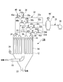
- the porous filter (dust removal device) 10A of the embodiment shown in FIG. 1 is a candle type porous filter system that removes dust from a gas containing dust.
- the porous filter 10 ⁇ / b> A includes a filter group including a number of porous filter elements 14 installed in the container body 12.
- the dust-containing gas including the dust is introduced into the container from the dust-containing gas introduction pipe 18 provided at the lower part of the container body 12. This dust-containing gas passes through the porous filter element 14 in the container body 12 and flows out from the clean gas outlet 20 to the outside of the container.
- Reference numeral 16 in the figure denotes a filter tube plate that supports a number of porous filter elements 14, and 22 denotes a dust discharge port that discharges the dust to the outside of the container body 12.
- the porous filter 10 ⁇ / b> A described above is collected by the porous filter element 14 through a filter group installed in the container body 12.
- the porous filter 10A includes a backwashing system that removes the dust layer by removing the dust layer in the opposite direction of the gas flow in order to remove the dust layer in the dust-containing gas that has grown on the filter surface.
- This backwashing system injects high-pressure gas (high-pressure medium for backwashing) such as nitrogen gas from the filter outlet side toward the filter back surface of the porous filter element 14, and generates a high-pressure gas flow in the direction opposite to the dust-containing gas.
- the dust layer that is formed and adhered to the filter surface is peeled off, and thereby backwashing is performed to remove the dust from the filter surface.
- Such backwashing is performed by repeatedly circulating and stopping the high-pressure gas by opening and closing a valve provided in the backwashing high-pressure medium supply system.
- the backwash system of the porous filter 10A includes a high pressure gas supply facility 30 such as a compressor that supplies high pressure gas to the backwash nozzle 34 as a high pressure medium supply source.
- the backwash high-pressure medium supply system for supplying high-pressure gas from the high-pressure gas supply equipment 30 to the backwash nozzle 34 has, for example, four backwash pipes 32a and 32b each having a backwash main pipe 31 connected to the high pressure gas supply equipment 30. , 32c, 32d.
- the backwash piping branch number it is not limited to four illustrated, It can change suitably according to the division
- the above-described backwash pipe 32a is provided with a backwash tank 42a as a high-pressure medium accumulator tank provided with an upstream backwash valve 38a and a downstream backwash valve 40a.
- a backwash tank 42b having an upstream backwash valve 38b and a downstream backwash valve 40b is installed in the backwash pipe 32b, and an upstream backwash valve 38c and a downstream side are provided in the backwash pipe 32c.
- a backwash tank 42c having a backwash valve 40c is installed, and a backwash tank 42d having an upstream backwash valve 38d and a downstream backwash valve 40d is installed in the backwash pipe 32d.
- the backwashing system of the present embodiment has a valve configuration in which two backwashing valves are installed in each backwashing system, and a backwashing tank is disposed between the two backwashing valves.
- the backwash pipe 32 when it is not necessary to distinguish between the cleaning areas, they will be referred to as the backwash pipe 32, the upstream side backwash valve 38, the downstream side backwash valve 40, and the backwash tank 42.
- the backwash main pipe 31 is provided with a high pressure gas pressure gauge 44 that detects the outlet pressure Pc of the high pressure gas in the vicinity of the outlet of the high pressure gas supply facility 30 (the inlet of the upstream backwash valve). Further, a filter inlet pressure gauge 24 for measuring the inlet gas pressure Pf of the porous filter element 14 is installed in the container main body 12 or the dust-containing gas introduction pipe 18.
- the backwashing high-pressure medium supply system that guides the backwashing high-pressure gas injected to the filter group of the porous filter element 14 from the high-pressure gas supply equipment 30 to the backwashing nozzle 34 in the washing area is the reverse of the high-pressure medium flow path.
- the main pipe 31 and the backwash pipes 32a, 32b, 32c, and 32d pass through the backwash pipes 32a, 32b, 32c, and 32d, respectively, and the upstream backwash valves 38a, 38b, 38c, and 38d
- Backwash tanks 42a, 42b, 42c, 42d provided with side backwash valves 40a, 40b, 40c, 40d are installed.
- a plurality of filter groups (four sets in the illustrated example) of the porous filter elements 14 installed in the container body 12 are provided. It is divided into cleaning areas. Such a division of the washing area can reduce the amount of high-pressure gas required for one backwash, so that a low-speed operation valve is adopted as the downstream backwash valve 40 using a small-capacity backwash tank 42. make it easier. Also, the high-pressure gas supply facility 30 can be downsized.
- backwash pipes 32a, 32b, 32c, and 32d that are branched and independent from the backwash main pipe 32 are provided for each cleaning area group, and upstream backwash valves 38a, 38b, 38c, and 38d are provided for each washing area. If the downstream backwash valves 40a, 40b, 40c, and 40d are opened and closed, the backwash for each backwash area can be performed sequentially. That is, the backwashing for each cleaning area is independent or divided in order to suppress the flow rate of the high-pressure gas used for backwashing and reduce the fluctuation of the flow generated in the dust-containing gas flowing in the container body 12 of the porous filter 10A. It is operated so that regular backwashing is performed every several groups.
- the outlet pressure Pc of the high pressure gas supply equipment 30 detected by the high pressure gas pressure gauge 44 is set so that the flow velocity of the high pressure gas injected from the backwash nozzle 34 becomes the speed of sound.
- the pressure is set to be equal to or higher than the critical pressure of the inlet gas pressure Pf detected by the filter inlet pressure gauge 24.
- the high pressure gas pressure Pc is set so that the ratio (Pf / Pc) of the filter inlet gas pressure Pf and the high pressure gas pressure Pc is equal to or lower than the critical pressure ratio.
- the inlet gas pressure Pf detected by the filter inlet pressure gauge 24 the flow velocity of the high-pressure gas injected from the backwash nozzle 34 on the upstream side can be more reliably set to the sound velocity.
- the critical pressure ratio is given by the following formula.
- ⁇ is a specific heat ratio
- ⁇ 1.4
- the backwash preparation operation includes a high pressure medium filling operation in which the downstream backwash valve 38 is closed and the upstream backwash valve 40 is opened to fill the backwash tank 42 with a high pressure gas to a predetermined pressure, and the upstream backwashing operation is performed. And a pressure holding operation for keeping the pressure in the backwash tank 42 at a predetermined pressure by closing the valve 38.
- the backwash preparation operation is a preparatory operation in which the backwash tank 42 is filled with high-pressure gas until a predetermined pressure is reached, and is brought into a backwashable state, and is usually detected by the high-pressure gas pressure gauge 44.
- the pressure is approximately the same as the outlet pressure Pc.
- the downstream backwash valve 40 is opened for a predetermined period of time, and a high pressure gas is supplied from the backwash tank 42 to the backwash nozzle 34, and the downstream backwash valve 40 is closed.
- the upstream backwash valve 38 is opened to refill the backwash tank 42 with high-pressure gas up to a predetermined pressure and the pressure is increased.
- the upstream backwash valve 38 is closed and the backwash tank 42 is closed. It is a series of valve opening / closing operations constituted by a refilling pressure maintaining operation for keeping the refilling pressure at a predetermined pressure. This back washing operation is sequentially performed after confirming the completion of the back washing operation for each of the plurality of washing areas.
- the backwash tank 42 is filled with high-pressure gas to a predetermined pressure (for example, outlet pressure Pc) to increase the pressure, and the upstream backwash valve 38 is closed to keep the pressure in the backwash tank 42 at the predetermined pressure.
- backwashing can be performed by supplying high-pressure gas from the backwash tank 42 to the backwash nozzle 34 one by one with respect to the plurality of divided wash areas.
- the backwash tank 42 that has finished backwashing can be refilled with high-pressure gas while backwashing other washing areas to prepare for the next backwashing.
- the capacity of the backwash tank 42 is preferably such that it can store the amount of high-pressure gas necessary for backwashing once or twice.
- the determination that the above-described backwashing operation for each cleaning area has been completed is made by outputting sequence commands to the upstream backwashing valve 38 and the downstream backwashing valve 40. That is, it is determined by confirming that a control command to the valve has been issued, not whether or not the valve operation is actually completed. For this reason, for example, even when the valve does not operate normally and stops in the middle, the output of the control command can be confirmed and the backwashing can be regarded as completed. Therefore, even if a malfunction of the valve occurs, backwashing for the next cleaning area is continued without being stopped, so even if a malfunction occurs in one valve, the entire backwashing system is stopped. There is nothing.
- the backwash tank 42 functioning as a buffer tank since the backwash tank 42 functioning as a buffer tank is installed between the upstream backwash valve 38 and the downstream backwash valve 40, the backwash tank 42 has a predetermined pressure. Therefore, even if a high speed operation valve is not applied to the downstream side backwash valve 40, the outlet pressure of the backwash nozzle 34 can be kept high and a high backwash effect can be obtained. Further, when the downstream backwash valve 40 is opened, the upstream backwash valve 38 provided on the upstream side of the backwash tank 42 is closed, so that the downstream backwash valve 40 opens and closes slowly. However, the amount of high-pressure gas flowing out from the backwash nozzle 34 to the porous filter element 14 in the washing area does not exceed the capacity of the backwash tank 42. Furthermore, since the pressure in the backwash tank 42 decreases with time, the flow rate of the high-pressure gas injected from the backwash nozzle 34 also decreases, and therefore the flow rate fluctuation of the dust-containing gas flowing in the container body 12 is small. Become.
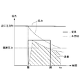
- FIG. 2 shows the pressure change and flow rate change of the high-pressure gas accompanying the opening and closing operation of the backwash valve at the time of backwashing.
- Changes in the conventional technology using a high speed operation valve as the backwash valve 36 are shown.
- a solid line indicates a change of the present invention (see FIG. 1) in which a low-speed operation valve is used as the downstream backwash valve 40 by a broken line.
- a high-speed operation valve is used as the backwash valve 36.
- the high-pressure gas having the outlet pressure Pc is supplied almost simultaneously with the opening of the valve. Is done.
- the backwash nozzle 34 is supplied with a flow rate of high-pressure gas corresponding to the outlet pressure Pc until the valve is closed. That is, the flow rate of the high-pressure gas instantaneously increases to the maximum value when the backwash valve 36 is opened, and the supply is continued until the valve is closed in this state.
- the amount of high-pressure gas supplied between the opening and closing of the backwash valve 36 that is, the amount of high-pressure gas used for one backwash is a rectangular region (showing a change in flow rate) indicated by a solid line in the figure. The area is surrounded by a rectangular area drawn by the line.
- the downstream backwash valve 40 of the low-speed valve is opened from the state where the backwash tank 42 is filled with the high pressure gas having the same pressure as the outlet pressure Pc. For this reason, the flow rate of the high-pressure gas reaches the maximum flow rate with a time delay from the opening of the valve.
- the pressure in the backwash tank 42 gradually decreases as the high-pressure gas flows out after the valve is opened, the flow rate also decreases with time. At this time, in order to make the high-pressure gas injected from the backwash nozzle 34 higher than the sonic velocity, the pressure in the backwash tank 40 needs to be higher than the critical pressure with respect to the filter inlet pressure.
- the amount of high-pressure gas supplied during this time is the area of the hatched area in the figure.
- the hatching section The area may be equal to or larger than the rectangular area described above.
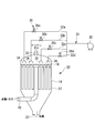
- a high-pressure gas tank 46 is installed as a high-pressure medium storage tank at the outlet of the high-pressure gas supply facility 30 that supplies high-pressure gas to the backwash system of the porous filter 10B.
- the high-pressure gas pressure gauge 44 that detects the outlet pressure Pc of the high-pressure gas is installed near the outlet of the high-pressure gas supply facility 30.
- a pressure gauge 44 ' is attached, and the same control as in the above-described embodiment is performed with the pressure detected by the high pressure gas pressure gauge 44' as the high pressure gas outlet pressure Pc.
- the high-pressure gas tank 46 that stores high-pressure gas of a predetermined pressure is installed at the outlet of the high-pressure gas supply facility 30, so that the pressure fluctuation on the high-pressure gas supply side is less than that in the case of direct supply.
- the filling pressure of the backwash tank 42 is stabilized.
- backwashing is performed efficiently and reliably, and the effect of separating and removing the dust layer from the filter surface of the porous filter element 14 is enhanced.
- the internal pressure of the high-pressure gas tank 46 is adopted as the outlet pressure Pc, more stable control is possible.
- the operation of the high pressure gas supply facility 30 is started / stopped or supplied / stopped by the outlet pressure Pc of the high pressure gas.
- the high pressure gas having the outlet pressure Pc is stored in the high pressure gas tank 46, backwashing is performed.
- the pressure fluctuation of the high pressure gas supplied to the tank 42 becomes moderate. Accordingly, the pressure fluctuation of the high pressure gas supplied to the backwash tank 42 is reduced and the pressure of the high pressure gas filled in the backwash tank 42 is also stabilized. Durability and reliability can be improved.
- the backwash tank pressure gauge 48 is installed in the backwash tank 42 to detect the backwash tank internal pressure Pt with respect to the backwash system of the porous filter 10C.
- backwash tank pressure gauges 48a, 48b, 48c, and 48d are respectively installed. Call a total of 48.
- the backwash tank pressure gauge 48 is installed in the backwash tank 42 in addition to the configuration described in the first embodiment, the upstream backwash valve 38 and the downstream backwash valve 38 are installed.
- the closing timing of the washing valve 40 instead of the outlet pressure Pc of the high pressure gas supply facility 30 detected by the high pressure gas pressure gauge 44, the pressure Pt in the back washing tank detected at a position closer to the back washing nozzle 34 is adopted. be able to.
- the closing timing of the upstream side backwash valve 38 is preferably such that the backwash tank pressure Pt is equal to or higher than the “1 / critical pressure ratio” of the inlet gas pressure Pf detected by the filter inlet pressure gauge 24.
- the pressure is set to be 1.15 times or more of the pressure due to the ratio.
- the closing timing of the downstream side backwash valve 40 decreases to 0.9 times or less of the critical pressure ratio at the latest when the backwash tank pressure Pt is lower than the “1 / critical pressure ratio” of the inlet gas pressure Pf. Set to be when.
- the pressure of the high pressure gas can be set to an appropriate value for backwashing. Therefore, the filter of the porous filter element 14 by backwashing can be set. The dust layer can be peeled and removed more effectively from the surface.
- excess high pressure gas can be removed. The outflow is prevented and the flow rate (consumption) of the high pressure gas for backwashing can be reduced.
- the closing timing of the upstream backwashing valve 38 in the pressure holding operation and the closing timing of the downstream backwashing valve 40 in the high pressure medium replenishment operation are determined based on the backwash tank internal pressure Pt. It becomes easy to set the pressure to the optimum pressure for backwashing.
- a fourth embodiment of the dust removing device according to the present invention will be described with reference to FIG.
- symbol is attached
- a high pressure gas tank 46 is installed at the outlet of the high pressure gas supply facility 30 and a control valve 50 is installed upstream of the high pressure gas tank 46 with respect to the backwash system of the porous filter 10D.
- a high-pressure gas pressure gauge 44 ' is attached to the high-pressure gas tank 46, and other configurations are the same as those of the third embodiment described above.
- the pressure control of the high pressure gas is performed using the pressure detected by the high pressure gas pressure gauge 44 '. That is, by installing the backwash tank pressure gauge 48 in the backwash tank 42, the pressure of the high-pressure gas can be set to an appropriate value for backwashing. Therefore, from the filter surface of the porous filter element 14 by backwashing. The dust layer can be peeled and removed more effectively. Further, since the pressure in the backwash tank 42 is lowered and the downstream backwash valve 40 is closed by monitoring the low pressure at which a sufficient backwash effect cannot be obtained, the high pressure gas flow for backwashing is reduced. be able to.
- the operation of the high-pressure gas supply facility 30 is started / stopped or supplied / stopped when the outlet pressure Pc of the high-pressure gas becomes equal to or higher than a predetermined pressure, but includes the high-pressure gas tank 46 and the control valve 50.
- Pressure fluctuation on the supply side becomes gradual.
- count of starting / stopping of the high pressure gas supply equipment 30 is reduced, and the reliability of equipment can be improved. Therefore, even when the backwashing system operates frequently, the backwash tank internal pressure Pt can be maintained at an appropriate pressure due to the gas reservoir effect of the high pressure gas tank 46.
- the pressure in the high-pressure gas tank 46 can be maintained at a predetermined value more reliably by operating the control valve 50 based on the outlet pressure Pc detected by the high-pressure gas pressure gauge 44 '.
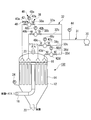
- a fifth embodiment of the dust removing device according to the present invention will be described with reference to FIG.
- symbol is attached
- a porous filter 10E in which a differential pressure gauge 26 for detecting the filter differential pressure DP of the filter group including the porous filter elements 14 is installed in the container body 12 is shown. Yes. That is, the porous filter 10E is configured to detect the differential pressure DP between the inlet side and the outlet side of the porous filter element 14 with the differential pressure gauge 26 and to control the pressure of the high pressure gas.
- the pressure control command for the high-pressure gas is determined from the increase / decrease in the resistance coefficient of the porous filter element 14 calculated from the filter differential pressure DP with respect to the high-pressure gas pressure control command.
- the pressure control command is appropriately changed so that the pressure becomes an appropriate pressure (for example, 5 kPa or less). That is, the filter differential pressure DP indicates the degree of dust adhering to the porous filter element 14, and by reflecting this, the pressure of the high-pressure gas used for backwashing can be optimized. Therefore, when the high pressure gas pressure control command reaches the upper limit of the high pressure gas supply facility 30, the control command can be changed so as to shorten the interval (cycle time) of the backwash system.
- the filter differential pressure DP can be maintained in an appropriate range, so that various operations of the porous filter 10E can be performed. It is possible to respond flexibly.
- the downstream backwash valve 40 and the upstream backwash valve 38 required for the backwash operation are provided. It is possible to apply a valve operating at low speed.
- the operating conditions of the backwash valve such as the reduction in the number of operations are improved, so the durability of the backwash valve is improved. As a result, the durability and operational reliability of the porous filter are improved.
- the upstream backwash valve 38 of the backwash tank 42 is closed, so the upper limit of the amount of high pressure gas for backwashing supplied to the filter group of the porous filter is backwashed.
- the capacity in the tank 42 is limited.
- the high-pressure gas flow rate for backwashing which is a factor that disturbs the flow of gas containing dust, is reduced, and the dust removal can be continued with a stable flow of dust-containing gas with little fluctuation. . Therefore, the operation stability is improved in the porous filter according to the above-described embodiment, and a plant such as a coal gasification combined cycle power generation facility and a pressurized fluidized bed combined power generation facility including the porous filter.
- the present invention can also be applied to an apparatus in which a backwash operation for circulating / stopping a high-pressure medium is frequently repeated and the operation is controlled by a valve.
- this invention is not limited to embodiment mentioned above, In the range which does not deviate from the summary, it can change suitably.
- Porous filter (dust removal device) 12 Container body 14 Porous filter element 18 Dust containing gas introduction pipe 20 Clean gas outlet 24 Filter inlet pressure gauge 26 Differential pressure gauge 30 High pressure gas supply equipment 31 Backwash main pipe 32, 32a, 32b, 32c, 32d Backwash pipe 34 Backwash Nozzle 38, 38a, 38b, 38c, 38d Upstream backwash valve 40, 40a, 40b, 40c, 40d Downstream backwash valve 42, 42a, 42b, 42c, 42d Backwash tank 44, 44 'High pressure gas pressure gauge 46 High pressure gas tank 48, 48a, 48b, 48c, 48d Backwash tank pressure gauge 50 Control valve
Landscapes
- Chemical & Material Sciences (AREA)
- Chemical Kinetics & Catalysis (AREA)
- Physics & Mathematics (AREA)
- Geometry (AREA)
- Filtering Of Dispersed Particles In Gases (AREA)
Priority Applications (8)
| Application Number | Priority Date | Filing Date | Title |
|---|---|---|---|
| CN201080034126.0A CN102470312B (zh) | 2009-09-30 | 2010-07-15 | 煤尘除去装置 |
| AU2010301972A AU2010301972B2 (en) | 2009-09-30 | 2010-07-15 | Soot and dust removal apparatus |
| US13/390,161 US8673066B2 (en) | 2009-09-30 | 2010-07-15 | Dust-removing method |
| SG2012008678A SG178314A1 (en) | 2009-09-30 | 2010-07-15 | Dust-removing apparatus |
| EP10820229A EP2484426A4 (en) | 2009-09-30 | 2010-07-15 | APPARATUS FOR REMOVING SOOT AND DUST |
| RU2012105037/02A RU2500457C2 (ru) | 2009-09-30 | 2010-07-15 | Устройство для удаления сажи и пыли |
| IN1013DEN2012 IN2012DN01013A (enExample) | 2009-09-30 | 2010-07-15 | |
| ZA2012/00754A ZA201200754B (en) | 2009-09-30 | 2012-01-31 | " dust removing apparatus " |
Applications Claiming Priority (2)
| Application Number | Priority Date | Filing Date | Title |
|---|---|---|---|
| JP2009-228590 | 2009-09-30 | ||
| JP2009228590A JP5665297B2 (ja) | 2009-09-30 | 2009-09-30 | 煤塵除去装置 |
Publications (1)
| Publication Number | Publication Date |
|---|---|
| WO2011040109A1 true WO2011040109A1 (ja) | 2011-04-07 |
Family
ID=43825943
Family Applications (1)
| Application Number | Title | Priority Date | Filing Date |
|---|---|---|---|
| PCT/JP2010/061943 Ceased WO2011040109A1 (ja) | 2009-09-30 | 2010-07-15 | 煤塵除去装置 |
Country Status (10)
| Country | Link |
|---|---|
| US (1) | US8673066B2 (enExample) |
| EP (1) | EP2484426A4 (enExample) |
| JP (1) | JP5665297B2 (enExample) |
| CN (1) | CN102470312B (enExample) |
| AU (1) | AU2010301972B2 (enExample) |
| IN (1) | IN2012DN01013A (enExample) |
| RU (1) | RU2500457C2 (enExample) |
| SG (1) | SG178314A1 (enExample) |
| WO (1) | WO2011040109A1 (enExample) |
| ZA (1) | ZA201200754B (enExample) |
Families Citing this family (11)
| Publication number | Priority date | Publication date | Assignee | Title |
|---|---|---|---|---|
| US8894744B2 (en) * | 2012-03-29 | 2014-11-25 | Alstom Technology Ltd | System and method of cleaning particulate collection devices used in a flue gas processing system |
| EP2913091B1 (en) * | 2014-02-26 | 2018-07-18 | General Electric Technology GmbH | Method for cleaning a fabric filter system |
| EP2937128A1 (de) * | 2014-04-25 | 2015-10-28 | Siemens VAI Metals Technologies GmbH | Überwachung einer druckgasbasierten Abreinigung bei einer Schlauchfilteranlage |
| CN104492177A (zh) * | 2014-12-25 | 2015-04-08 | 江阴中南重工股份有限公司 | 一种分离器 |
| CN108292603B (zh) * | 2016-01-06 | 2022-06-28 | 东芝三菱电机产业系统株式会社 | 气体供给装置 |
| US10272382B2 (en) * | 2016-05-31 | 2019-04-30 | United Technologies Corporation | Carrier gas reclamation system and method |
| CN106178723B (zh) * | 2016-08-31 | 2019-02-19 | 江苏沃尔夫智能科技有限公司 | 一种脉冲滤芯式车载除尘器 |
| CN110130889B (zh) * | 2019-06-18 | 2024-06-21 | 中国矿业大学(北京) | 除尘装置、泡沫除尘设备及掘进机 |
| GB2592267A (en) * | 2020-02-24 | 2021-08-25 | Altair Uk Ltd | Pulse nozzle for filter cleaning systems |
| JP7441690B2 (ja) * | 2020-03-19 | 2024-03-01 | 三機工業株式会社 | 固気分離装置におけるろ過材の逆洗システムおよび逆洗方法 |
| JP2024115931A (ja) * | 2023-02-15 | 2024-08-27 | 株式会社日立産機システム | 診断システム、および処理装置 |
Citations (8)
| Publication number | Priority date | Publication date | Assignee | Title |
|---|---|---|---|---|
| JPH0691123A (ja) * | 1992-09-10 | 1994-04-05 | Mitsubishi Heavy Ind Ltd | 脱塵器の逆洗装置 |
| JPH06190229A (ja) * | 1992-12-25 | 1994-07-12 | Hitachi Plant Eng & Constr Co Ltd | 集塵機 |
| JPH08155235A (ja) * | 1994-12-08 | 1996-06-18 | Mitsubishi Heavy Ind Ltd | 脱塵器用逆洗装置 |
| JP3128261B2 (ja) | 1991-04-24 | 2001-01-29 | 旭硝子株式会社 | 高温ガス除塵器用逆洗装置および高温ガス除塵器の逆洗方法 |
| JP2002241770A (ja) * | 2001-02-22 | 2002-08-28 | Electric Power Dev Co Ltd | 石炭ガス化発電プラント及びフィルタ逆洗装置 |
| JP2004525052A (ja) * | 2000-12-15 | 2004-08-19 | ソシエテ フランコ ベルジュ ド ファブリカシオン ド コンビスティブル エフベーエフセ | フィルターの目詰まり除去方法及び装置 |
| JP2007090222A (ja) * | 2005-09-28 | 2007-04-12 | Hitachi Plant Technologies Ltd | バグフィルタ集塵装置 |
| JP2009113014A (ja) * | 2007-11-09 | 2009-05-28 | Mitsubishi Heavy Ind Ltd | バグフィルタ構造 |
Family Cites Families (15)
| Publication number | Priority date | Publication date | Assignee | Title |
|---|---|---|---|---|
| DE2529464A1 (de) * | 1975-07-02 | 1977-01-27 | Mikropul Mahl & Staubtech Gmbh | Verfahren und vorrichtung zum abreinigen von filter-hohlkoerpern in filteranlagen |
| US4445912A (en) | 1982-02-04 | 1984-05-01 | The Mike Volk Co., Inc. | Effluent air filtration apparatus |
| US4492003A (en) * | 1983-07-25 | 1985-01-08 | Boylan John F | Filter cleaning device |
| CA1324773C (en) * | 1988-01-16 | 1993-11-30 | Noriyuki Oda | Supporting structure for ceramic tubes in a gas system |
| JPH062209B2 (ja) * | 1989-06-30 | 1994-01-12 | 日本碍子株式会社 | 除塵機の逆洗方法及び除塵機 |
| JPH03128261A (ja) | 1989-10-13 | 1991-05-31 | Mita Ind Co Ltd | 文字発生装置 |
| US5242472A (en) * | 1990-08-17 | 1993-09-07 | A. Ahlstrom Corporation | Flow restrictor in a pulse cleaning system |
| RU1777933C (ru) | 1990-08-29 | 1992-11-30 | Государственный Проектный Институт "Проектпромвентиляция" | Пылеуловитель |
| US5616171A (en) * | 1994-01-07 | 1997-04-01 | Donaldson Company, Inc. | Pulse jet filter cleaning system |
| SE515633C2 (sv) | 2000-01-31 | 2001-09-17 | Abb Alstom Power Nv | Förfarande vid rensning av spärrfilter |
| AU3048301A (en) | 2000-02-14 | 2001-08-20 | Milow Ltd. | Filter-cleaning device and method, and fluid pulse generator particularly usefultherein |
| US7163382B1 (en) * | 2003-04-09 | 2007-01-16 | Black & Decker Inc. | Suitcase style air compressor assembly |
| US6638344B2 (en) * | 2001-09-11 | 2003-10-28 | Mcneilus Truck And Manufacturing, Inc. | Plenum pulsed filter vent |
| CN100490937C (zh) | 2005-05-08 | 2009-05-27 | 山东省冶金设计院 | 布袋脉冲反吹除尘装置 |
| US20070199593A1 (en) * | 2006-02-10 | 2007-08-30 | Mends Frank P | Devices and methods for controlling fluid flow through conduits |
-
2009
- 2009-09-30 JP JP2009228590A patent/JP5665297B2/ja active Active
-
2010
- 2010-07-15 IN IN1013DEN2012 patent/IN2012DN01013A/en unknown
- 2010-07-15 RU RU2012105037/02A patent/RU2500457C2/ru not_active IP Right Cessation
- 2010-07-15 WO PCT/JP2010/061943 patent/WO2011040109A1/ja not_active Ceased
- 2010-07-15 EP EP10820229A patent/EP2484426A4/en not_active Withdrawn
- 2010-07-15 CN CN201080034126.0A patent/CN102470312B/zh active Active
- 2010-07-15 SG SG2012008678A patent/SG178314A1/en unknown
- 2010-07-15 AU AU2010301972A patent/AU2010301972B2/en not_active Ceased
- 2010-07-15 US US13/390,161 patent/US8673066B2/en active Active
-
2012
- 2012-01-31 ZA ZA2012/00754A patent/ZA201200754B/en unknown
Patent Citations (8)
| Publication number | Priority date | Publication date | Assignee | Title |
|---|---|---|---|---|
| JP3128261B2 (ja) | 1991-04-24 | 2001-01-29 | 旭硝子株式会社 | 高温ガス除塵器用逆洗装置および高温ガス除塵器の逆洗方法 |
| JPH0691123A (ja) * | 1992-09-10 | 1994-04-05 | Mitsubishi Heavy Ind Ltd | 脱塵器の逆洗装置 |
| JPH06190229A (ja) * | 1992-12-25 | 1994-07-12 | Hitachi Plant Eng & Constr Co Ltd | 集塵機 |
| JPH08155235A (ja) * | 1994-12-08 | 1996-06-18 | Mitsubishi Heavy Ind Ltd | 脱塵器用逆洗装置 |
| JP2004525052A (ja) * | 2000-12-15 | 2004-08-19 | ソシエテ フランコ ベルジュ ド ファブリカシオン ド コンビスティブル エフベーエフセ | フィルターの目詰まり除去方法及び装置 |
| JP2002241770A (ja) * | 2001-02-22 | 2002-08-28 | Electric Power Dev Co Ltd | 石炭ガス化発電プラント及びフィルタ逆洗装置 |
| JP2007090222A (ja) * | 2005-09-28 | 2007-04-12 | Hitachi Plant Technologies Ltd | バグフィルタ集塵装置 |
| JP2009113014A (ja) * | 2007-11-09 | 2009-05-28 | Mitsubishi Heavy Ind Ltd | バグフィルタ構造 |
Non-Patent Citations (1)
| Title |
|---|
| See also references of EP2484426A4 |
Also Published As
| Publication number | Publication date |
|---|---|
| CN102470312A (zh) | 2012-05-23 |
| EP2484426A4 (en) | 2013-04-03 |
| IN2012DN01013A (enExample) | 2015-04-10 |
| RU2500457C2 (ru) | 2013-12-10 |
| SG178314A1 (en) | 2012-03-29 |
| AU2010301972B2 (en) | 2015-01-22 |
| EP2484426A1 (en) | 2012-08-08 |
| CN102470312B (zh) | 2015-09-09 |
| JP5665297B2 (ja) | 2015-02-04 |
| US8673066B2 (en) | 2014-03-18 |
| US20120137890A1 (en) | 2012-06-07 |
| ZA201200754B (en) | 2012-09-26 |
| JP2011072946A (ja) | 2011-04-14 |
| AU2010301972A1 (en) | 2012-03-08 |
| RU2012105037A (ru) | 2013-08-20 |
Similar Documents
| Publication | Publication Date | Title |
|---|---|---|
| JP5665297B2 (ja) | 煤塵除去装置 | |
| JP5006262B2 (ja) | フィルタのバックフラッシュ方法 | |
| JP5379401B2 (ja) | 連続的処理形態で行われる、流れろ過システム内におけるプレナム利用の高圧のブローバックガス送り出しシステム | |
| CN104955549A (zh) | 排气净化装置 | |
| JP5216692B2 (ja) | 集塵装置 | |
| CN102264447A (zh) | 用于浆料反应器的产物过滤系统 | |
| CN102099092B (zh) | 过滤器的反洗装置 | |
| CN110935249A (zh) | 一种空气过滤器自洁控制方法及装置 | |
| JPH0751212B2 (ja) | 高温ガスから粒子を分離する装置及び方法 | |
| JP3702254B2 (ja) | 濾過装置の逆洗方法及び逆洗装置 | |
| JP6332814B2 (ja) | フィルタ装置およびフィルタ要素を洗浄する方法 | |
| CN103127786A (zh) | 集尘装置 | |
| CN212894102U (zh) | 一种反硝化深床滤池驱氮控制系统 | |
| CN112370873B (zh) | 一种高温粗合成气成套过滤系统 | |
| US12157441B2 (en) | Vehicle wash reverse osmosis system | |
| JP2023055170A (ja) | バグフィルタ | |
| CN222239060U (zh) | 一种过滤系统和干雾抑尘系统 | |
| JPH0929032A (ja) | 集じん装置 | |
| JP2025180362A (ja) | 集塵機の逆圧洗浄装置 | |
| JP3197144B2 (ja) | セラミックフィルタの逆洗装置 | |
| JP2001000813A (ja) | ろ過装置 | |
| JP2009226345A (ja) | 膜ろ過装置の逆洗方法および装置 | |
| JP2009543691A (ja) | 高純度材料を処理するシステムおよび方法 |
Legal Events
| Date | Code | Title | Description |
|---|---|---|---|
| WWE | Wipo information: entry into national phase |
Ref document number: 201080034126.0 Country of ref document: CN |
|
| 121 | Ep: the epo has been informed by wipo that ep was designated in this application |
Ref document number: 10820229 Country of ref document: EP Kind code of ref document: A1 |
|
| WWE | Wipo information: entry into national phase |
Ref document number: 1013/DELNP/2012 Country of ref document: IN |
|
| WWE | Wipo information: entry into national phase |
Ref document number: 2010301972 Country of ref document: AU |
|
| WWE | Wipo information: entry into national phase |
Ref document number: 13390161 Country of ref document: US Ref document number: 2010820229 Country of ref document: EP |
|
| WWE | Wipo information: entry into national phase |
Ref document number: 2012105037 Country of ref document: RU |
|
| ENP | Entry into the national phase |
Ref document number: 2010301972 Country of ref document: AU Date of ref document: 20100715 Kind code of ref document: A |
|
| NENP | Non-entry into the national phase |
Ref country code: DE |
|
| WWE | Wipo information: entry into national phase |
Ref document number: 1201000624 Country of ref document: TH |