WO2011037119A1 - Liquid crystal display device - Google Patents
Liquid crystal display device Download PDFInfo
- Publication number
- WO2011037119A1 WO2011037119A1 PCT/JP2010/066348 JP2010066348W WO2011037119A1 WO 2011037119 A1 WO2011037119 A1 WO 2011037119A1 JP 2010066348 W JP2010066348 W JP 2010066348W WO 2011037119 A1 WO2011037119 A1 WO 2011037119A1
- Authority
- WO
- WIPO (PCT)
- Prior art keywords
- liquid crystal
- film
- group
- rth
- crystal display
- Prior art date
Links
Images


Classifications
-
- G—PHYSICS
- G02—OPTICS
- G02F—OPTICAL DEVICES OR ARRANGEMENTS FOR THE CONTROL OF LIGHT BY MODIFICATION OF THE OPTICAL PROPERTIES OF THE MEDIA OF THE ELEMENTS INVOLVED THEREIN; NON-LINEAR OPTICS; FREQUENCY-CHANGING OF LIGHT; OPTICAL LOGIC ELEMENTS; OPTICAL ANALOGUE/DIGITAL CONVERTERS
- G02F1/00—Devices or arrangements for the control of the intensity, colour, phase, polarisation or direction of light arriving from an independent light source, e.g. switching, gating or modulating; Non-linear optics
- G02F1/01—Devices or arrangements for the control of the intensity, colour, phase, polarisation or direction of light arriving from an independent light source, e.g. switching, gating or modulating; Non-linear optics for the control of the intensity, phase, polarisation or colour
- G02F1/13—Devices or arrangements for the control of the intensity, colour, phase, polarisation or direction of light arriving from an independent light source, e.g. switching, gating or modulating; Non-linear optics for the control of the intensity, phase, polarisation or colour based on liquid crystals, e.g. single liquid crystal display cells
- G02F1/137—Devices or arrangements for the control of the intensity, colour, phase, polarisation or direction of light arriving from an independent light source, e.g. switching, gating or modulating; Non-linear optics for the control of the intensity, phase, polarisation or colour based on liquid crystals, e.g. single liquid crystal display cells characterised by the electro-optical or magneto-optical effect, e.g. field-induced phase transition, orientation effect, guest-host interaction or dynamic scattering
-
- G—PHYSICS
- G02—OPTICS
- G02F—OPTICAL DEVICES OR ARRANGEMENTS FOR THE CONTROL OF LIGHT BY MODIFICATION OF THE OPTICAL PROPERTIES OF THE MEDIA OF THE ELEMENTS INVOLVED THEREIN; NON-LINEAR OPTICS; FREQUENCY-CHANGING OF LIGHT; OPTICAL LOGIC ELEMENTS; OPTICAL ANALOGUE/DIGITAL CONVERTERS
- G02F1/00—Devices or arrangements for the control of the intensity, colour, phase, polarisation or direction of light arriving from an independent light source, e.g. switching, gating or modulating; Non-linear optics
- G02F1/01—Devices or arrangements for the control of the intensity, colour, phase, polarisation or direction of light arriving from an independent light source, e.g. switching, gating or modulating; Non-linear optics for the control of the intensity, phase, polarisation or colour
- G02F1/13—Devices or arrangements for the control of the intensity, colour, phase, polarisation or direction of light arriving from an independent light source, e.g. switching, gating or modulating; Non-linear optics for the control of the intensity, phase, polarisation or colour based on liquid crystals, e.g. single liquid crystal display cells
- G02F1/133—Constructional arrangements; Operation of liquid crystal cells; Circuit arrangements
- G02F1/1333—Constructional arrangements; Manufacturing methods
- G02F1/1334—Constructional arrangements; Manufacturing methods based on polymer dispersed liquid crystals, e.g. microencapsulated liquid crystals
-
- G—PHYSICS
- G02—OPTICS
- G02B—OPTICAL ELEMENTS, SYSTEMS OR APPARATUS
- G02B5/00—Optical elements other than lenses
- G02B5/30—Polarising elements
- G02B5/3083—Birefringent or phase retarding elements
-
- G—PHYSICS
- G02—OPTICS
- G02F—OPTICAL DEVICES OR ARRANGEMENTS FOR THE CONTROL OF LIGHT BY MODIFICATION OF THE OPTICAL PROPERTIES OF THE MEDIA OF THE ELEMENTS INVOLVED THEREIN; NON-LINEAR OPTICS; FREQUENCY-CHANGING OF LIGHT; OPTICAL LOGIC ELEMENTS; OPTICAL ANALOGUE/DIGITAL CONVERTERS
- G02F1/00—Devices or arrangements for the control of the intensity, colour, phase, polarisation or direction of light arriving from an independent light source, e.g. switching, gating or modulating; Non-linear optics
- G02F1/01—Devices or arrangements for the control of the intensity, colour, phase, polarisation or direction of light arriving from an independent light source, e.g. switching, gating or modulating; Non-linear optics for the control of the intensity, phase, polarisation or colour
- G02F1/13—Devices or arrangements for the control of the intensity, colour, phase, polarisation or direction of light arriving from an independent light source, e.g. switching, gating or modulating; Non-linear optics for the control of the intensity, phase, polarisation or colour based on liquid crystals, e.g. single liquid crystal display cells
- G02F1/133—Constructional arrangements; Operation of liquid crystal cells; Circuit arrangements
- G02F1/1333—Constructional arrangements; Manufacturing methods
- G02F1/1335—Structural association of cells with optical devices, e.g. polarisers or reflectors
- G02F1/133528—Polarisers
-
- G—PHYSICS
- G02—OPTICS
- G02F—OPTICAL DEVICES OR ARRANGEMENTS FOR THE CONTROL OF LIGHT BY MODIFICATION OF THE OPTICAL PROPERTIES OF THE MEDIA OF THE ELEMENTS INVOLVED THEREIN; NON-LINEAR OPTICS; FREQUENCY-CHANGING OF LIGHT; OPTICAL LOGIC ELEMENTS; OPTICAL ANALOGUE/DIGITAL CONVERTERS
- G02F1/00—Devices or arrangements for the control of the intensity, colour, phase, polarisation or direction of light arriving from an independent light source, e.g. switching, gating or modulating; Non-linear optics
- G02F1/01—Devices or arrangements for the control of the intensity, colour, phase, polarisation or direction of light arriving from an independent light source, e.g. switching, gating or modulating; Non-linear optics for the control of the intensity, phase, polarisation or colour
- G02F1/13—Devices or arrangements for the control of the intensity, colour, phase, polarisation or direction of light arriving from an independent light source, e.g. switching, gating or modulating; Non-linear optics for the control of the intensity, phase, polarisation or colour based on liquid crystals, e.g. single liquid crystal display cells
- G02F1/133—Constructional arrangements; Operation of liquid crystal cells; Circuit arrangements
- G02F1/1333—Constructional arrangements; Manufacturing methods
- G02F1/1335—Structural association of cells with optical devices, e.g. polarisers or reflectors
- G02F1/13363—Birefringent elements, e.g. for optical compensation
-
- G—PHYSICS
- G02—OPTICS
- G02F—OPTICAL DEVICES OR ARRANGEMENTS FOR THE CONTROL OF LIGHT BY MODIFICATION OF THE OPTICAL PROPERTIES OF THE MEDIA OF THE ELEMENTS INVOLVED THEREIN; NON-LINEAR OPTICS; FREQUENCY-CHANGING OF LIGHT; OPTICAL LOGIC ELEMENTS; OPTICAL ANALOGUE/DIGITAL CONVERTERS
- G02F1/00—Devices or arrangements for the control of the intensity, colour, phase, polarisation or direction of light arriving from an independent light source, e.g. switching, gating or modulating; Non-linear optics
- G02F1/01—Devices or arrangements for the control of the intensity, colour, phase, polarisation or direction of light arriving from an independent light source, e.g. switching, gating or modulating; Non-linear optics for the control of the intensity, phase, polarisation or colour
- G02F1/13—Devices or arrangements for the control of the intensity, colour, phase, polarisation or direction of light arriving from an independent light source, e.g. switching, gating or modulating; Non-linear optics for the control of the intensity, phase, polarisation or colour based on liquid crystals, e.g. single liquid crystal display cells
- G02F1/133—Constructional arrangements; Operation of liquid crystal cells; Circuit arrangements
- G02F1/1333—Constructional arrangements; Manufacturing methods
- G02F1/1343—Electrodes
- G02F1/134309—Electrodes characterised by their geometrical arrangement
- G02F1/134363—Electrodes characterised by their geometrical arrangement for applying an electric field parallel to the substrate, i.e. in-plane switching [IPS]
-
- G—PHYSICS
- G02—OPTICS
- G02F—OPTICAL DEVICES OR ARRANGEMENTS FOR THE CONTROL OF LIGHT BY MODIFICATION OF THE OPTICAL PROPERTIES OF THE MEDIA OF THE ELEMENTS INVOLVED THEREIN; NON-LINEAR OPTICS; FREQUENCY-CHANGING OF LIGHT; OPTICAL LOGIC ELEMENTS; OPTICAL ANALOGUE/DIGITAL CONVERTERS
- G02F1/00—Devices or arrangements for the control of the intensity, colour, phase, polarisation or direction of light arriving from an independent light source, e.g. switching, gating or modulating; Non-linear optics
- G02F1/01—Devices or arrangements for the control of the intensity, colour, phase, polarisation or direction of light arriving from an independent light source, e.g. switching, gating or modulating; Non-linear optics for the control of the intensity, phase, polarisation or colour
- G02F1/13—Devices or arrangements for the control of the intensity, colour, phase, polarisation or direction of light arriving from an independent light source, e.g. switching, gating or modulating; Non-linear optics for the control of the intensity, phase, polarisation or colour based on liquid crystals, e.g. single liquid crystal display cells
- G02F1/137—Devices or arrangements for the control of the intensity, colour, phase, polarisation or direction of light arriving from an independent light source, e.g. switching, gating or modulating; Non-linear optics for the control of the intensity, phase, polarisation or colour based on liquid crystals, e.g. single liquid crystal display cells characterised by the electro-optical or magneto-optical effect, e.g. field-induced phase transition, orientation effect, guest-host interaction or dynamic scattering
- G02F1/13775—Polymer-stabilized liquid crystal layers
-
- G—PHYSICS
- G02—OPTICS
- G02F—OPTICAL DEVICES OR ARRANGEMENTS FOR THE CONTROL OF LIGHT BY MODIFICATION OF THE OPTICAL PROPERTIES OF THE MEDIA OF THE ELEMENTS INVOLVED THEREIN; NON-LINEAR OPTICS; FREQUENCY-CHANGING OF LIGHT; OPTICAL LOGIC ELEMENTS; OPTICAL ANALOGUE/DIGITAL CONVERTERS
- G02F1/00—Devices or arrangements for the control of the intensity, colour, phase, polarisation or direction of light arriving from an independent light source, e.g. switching, gating or modulating; Non-linear optics
- G02F1/01—Devices or arrangements for the control of the intensity, colour, phase, polarisation or direction of light arriving from an independent light source, e.g. switching, gating or modulating; Non-linear optics for the control of the intensity, phase, polarisation or colour
- G02F1/13—Devices or arrangements for the control of the intensity, colour, phase, polarisation or direction of light arriving from an independent light source, e.g. switching, gating or modulating; Non-linear optics for the control of the intensity, phase, polarisation or colour based on liquid crystals, e.g. single liquid crystal display cells
- G02F1/137—Devices or arrangements for the control of the intensity, colour, phase, polarisation or direction of light arriving from an independent light source, e.g. switching, gating or modulating; Non-linear optics for the control of the intensity, phase, polarisation or colour based on liquid crystals, e.g. single liquid crystal display cells characterised by the electro-optical or magneto-optical effect, e.g. field-induced phase transition, orientation effect, guest-host interaction or dynamic scattering
- G02F1/13793—Blue phases
-
- G—PHYSICS
- G02—OPTICS
- G02F—OPTICAL DEVICES OR ARRANGEMENTS FOR THE CONTROL OF LIGHT BY MODIFICATION OF THE OPTICAL PROPERTIES OF THE MEDIA OF THE ELEMENTS INVOLVED THEREIN; NON-LINEAR OPTICS; FREQUENCY-CHANGING OF LIGHT; OPTICAL LOGIC ELEMENTS; OPTICAL ANALOGUE/DIGITAL CONVERTERS
- G02F2413/00—Indexing scheme related to G02F1/13363, i.e. to birefringent elements, e.g. for optical compensation, characterised by the number, position, orientation or value of the compensation plates
Definitions
- the present invention relates to improvement of display characteristics of a liquid crystal display device using a polymer-stabilized blue phase.
- Liquid crystal display elements are widely used in the field of optical information processing.
- liquid crystal display methods such as TN, STN, IPS, VA, and OCB methods
- the alignment of liquid crystal molecules that is controlled in advance between two polarizing plates varies depending on the applied electric field.
- display is performed by changing the state of light, changing the polarization direction or polarization state of light, and changing the amount of transmitted light.
- All of these conventional liquid crystal display systems require a surface alignment process for controlling the alignment of liquid crystal molecules, and in particular, a system other than VA requires a rubbing process.
- the rubbing is an operation of rubbing the surface of the alignment film applied to the substrate surface in contact with the liquid crystal with a cloth or the like, which causes a decrease in yield, an increase in cost due to the decrease, and a decrease in display quality.
- the response time is about 5 milliseconds at the shortest, and there is a limit to the display of moving images on a television.
- Patent Documents 1 and 2 chiral nematic liquid crystals have been developed as liquid crystals for liquid crystal display elements.
- use of a polymer-stabilized blue phase has been proposed in place of conventional nematic liquid crystals (Patent Documents 3 and 4).
- This polymer-stabilized blue phase is a novel material whose expression temperature range is significantly increased by a polymer without losing the high-speed response characteristic of the blue phase. Since the polymer-stabilized blue phase is optically isotropic when no electric field is applied, it is not necessary to control the orientation. Display is performed by a novel method that utilizes a phenomenon in which retardation is induced by application of an electric field without retardation at zero electric field.
- the present inventors have the above advantages, but the front (normal direction to the display surface) CR is lower than other liquid crystal display methods. I found out that there was a problem. In recent years, since the liquid crystal display device has been improved in CR, it is strongly desired to improve the front CR of the liquid crystal display device using the polymer-stabilized blue phase.
- the present invention has been made in view of the above problems, and an object thereof is to improve the front CR of a liquid crystal display device using a polymer-stabilized blue phase.
- the present inventors diligently studied.
- One of the causes of the low front CR of the liquid crystal display device using the polymer-stabilized blue phase is that the blue phase is stabilized for the blue phase.
- the reaction did not proceed sufficiently.
- the color filter substrate and the array substrate of the liquid crystal cell hinder the transmission of ultraviolet rays, the entire surface or part of the liquid crystal cell is not uniformly irradiated with ultraviolet rays, and the progress of the photocrosslinking reaction is hindered. all right.
- a liquid crystal cell having a light source, a first polarizer, a first transparent film, a pair of transparent substrates and a polymer-stabilized blue phase liquid crystal disposed therebetween, a second transparent film, and a second A liquid crystal display device, wherein polarizers are arranged in this order, one of a pair of transparent substrates is an array substrate, and a color filter layer is not arranged on the other transparent substrate.
- the array substrate is a color filter-on-array substrate.
- the liquid crystal display device according to [1] or [2], which includes a backlight unit that sequentially emits independent three primary color lights and is driven by a field sequential driving method.
- of the in-plane retardation Re (550) at a wavelength of 550 nm of the first transparent film is 20 nm or less and the thickness direction retardation Rth (550) of the same wavelength is less than 20 nm.
- of the in-plane retardation Re (550) at a wavelength of 550 nm of the first transparent film is 10 nm or less and the thickness direction retardation Rth (550) of the same wavelength is [4]
- the liquid crystal display device having an absolute value
- of the first transparent film is 10 nm or less and
- the second transparent film is a biaxial film having Re (550) of 200 to 350 nm and Rth (550) of ⁇ 88 to 88 nm.
- Liquid crystal display device [16]
- the second transparent film is a biaxial film in which Re (550) is 20 to 120 nm and Rth (550) is 125 to 225 nm, and Re (550) is ⁇ 30 to 30 nm.
- the liquid crystal display device according to any one of [1] to [11], further including a biaxial film having Rth (550) of 50 to 150 nm.
- the second transparent film has a Re (550) of 60 to 210 nm and a Rth (550) of 30 to 105 nm, and Re (550) of ⁇ 30 to 30 nm.
- the present invention by using a polymer-stabilized blue phase, it is possible to provide a liquid crystal display device having a high response speed and an improved front CR.
- FIG. 1 is a schematic cross-sectional view of an example of a COA substrate that can be used in the present invention. It is a cross-sectional schematic diagram of an example of the counter substrate of the COA substrate that can be used in the present invention. It is sectional drawing which shows an example of the liquid crystal display element which can be utilized for this invention. It is sectional drawing which shows an example of the liquid crystal display element which can be utilized for this invention. It is a top view which shows the structural example of the electrode of the liquid crystal display element which can be utilized for this invention.
- (A) is sectional drawing which shows typically the schematic structure of the principal part of the said display element in an electric field no application state
- (b) shows typically the schematic structure of the principal part of the said display element in an electric field application state.
- It is a sectional view It is a block diagram which shows schematic structure of the principal part of an example of the display apparatus of this invention. It is a top view which shows the structural example of the electrode of the liquid crystal display element which can be utilized for this invention.
- Re ( ⁇ ) and Rth ( ⁇ ) represent in-plane retardation (unit: nm) and retardation in the thickness direction (unit: nm) at wavelength ⁇ , respectively.
- Re ( ⁇ ) is measured by making light with a wavelength of ⁇ nm incident in the normal direction of the film in KOBRA 21ADH or WR (manufactured by Oji Scientific Instruments).
- Rth ( ⁇ ) is calculated by the following method.
- Rth ( ⁇ ) is Re ( ⁇ )
- the in-plane slow axis (determined by KOBRA 21ADH or WR) is the tilt axis (rotation axis) (if there is no slow axis, any in-plane film surface)
- the light of wavelength ⁇ nm is incident from each of the inclined directions in steps of 10 degrees from the normal direction to 50 degrees on one side with respect to the film normal direction (with the direction of the rotation axis as the rotation axis).
- KOBRA 21ADH or WR is calculated based on the measured retardation value, the assumed value of the average refractive index, and the input film thickness value.
- Re ( ⁇ ) represents a retardation value in a direction inclined by an angle ⁇ from the normal direction.
- nx represents the refractive index in the slow axis direction in the plane
- ny represents the refractive index in the direction orthogonal to nx in the plane
- nz represents the refractive index in the direction orthogonal to nx and ny.
- d represents the film thickness of the film.
- Rth ( ⁇ ) is calculated by the following method.
- Rth ( ⁇ ) is from ⁇ 50 degrees to +50 degrees with respect to the normal direction of the film, with Re ( ⁇ ) being the in-plane slow axis (determined by KOBRA 21ADH or WR) and the tilt axis (rotating axis).
- Re ( ⁇ ) being the in-plane slow axis (determined by KOBRA 21ADH or WR) and the tilt axis (rotating axis).
- ⁇ nm is incident from the inclined direction and measured at 11 points. Based on the measured retardation value, the assumed average refractive index, and the input film thickness value, KOBRA 21ADH or Calculated by WR.
- the assumed value of the average refractive index the values of Polymer Handbook (John Wiley & Sons, Inc.) and catalogs of various optical films can be used. Those whose average refractive index is not known can be measured with an Abbe refractometer. Examples of the average refractive index values of main optical films are given below: Cellulose acylate (1.48), cycloolefin polymer (1.52), polycarbonate (1.59), polymethyl methacrylate (1.49), and polystyrene (1.59). The KOBRA 21ADH or WR calculates nx, ny, and nz by inputting the assumed value of the average refractive index and the film thickness.
- Nz (nx ⁇ nz) / (nx ⁇ ny) is further calculated from the calculated nx, ny, and nz.
- the measurement wavelength is 550 nm.
- the “in-plane slow axis” is the direction in which the refractive index is maximized in the plane, and the “in-plane slow axis” is the direction orthogonal to the in-plane slow axis in the plane.
- the visible light region means a wavelength of 380 to 780 nm.
- the present invention relates to a liquid crystal display device using a polymer-stabilized blue phase, and in particular, a high-level display in which an array substrate is disposed on one of a pair of substrates of a liquid crystal cell and a counter substrate without a color filter layer is disposed on the other.
- the present invention relates to a liquid crystal display device using a molecule-stabilized blue phase. It is known that a liquid crystal display device using a polymer-stabilized blue phase does not need to control orientation, has a high response speed, and exhibits a wide viewing angle characteristic. However, as a result of examination by the present inventors, it was found that the front CR is inferior to other liquid crystal display methods. One of the causes is an alignment defect in the liquid crystal layer.
- the polymer-stabilized blue phase has a structure in which the blue phase liquid crystal is stabilized by a polymer network, and therefore the liquid crystal alignment tends to be non-uniform and alignment defects are likely to occur.
- the front (normal direction with respect to the display surface) CR decreases due to the scattering phenomenon by the liquid crystal at the alignment defect portion. This orientation defect is more likely to occur as the polymer network is insufficiently formed.
- the color filter substrate and the array substrate of the liquid crystal cell impede the transmission of ultraviolet rays. Therefore, the entire surface or part of the liquid crystal cell is not uniformly irradiated with ultraviolet rays, and the photocrosslinking reaction occurs. It turned out that the progress was hindered. As a result, the reaction does not proceed sufficiently and the formation of the polymer network becomes insufficient, which contributes to the generation of orientation defects. Conventionally, since an array substrate is disposed on one of a pair of substrates of a liquid crystal cell and a color filter substrate is disposed on the other, the photo-crosslinking reaction or the like becomes insufficient even when irradiated with ultraviolet rays from either side.
- an array substrate is disposed on one of a pair of substrates of a liquid crystal cell, and a counter substrate having no color filter layer is disposed on the other. Therefore, when ultraviolet rays are irradiated from the counter substrate side, the light is transmitted by the color filter.
- the blue phase liquid crystal can be uniformly irradiated with ultraviolet rays without disturbing the above.
- the photocrosslinking reaction can proceed stably and sufficiently, and a polymer network for stabilizing the blue phase can be stably formed. If the blue phase is further stabilized by the polymer network, alignment defects are less likely to occur, and as a result, the reduction in front CR due to light scattering by the liquid crystal in the alignment defect portion can be reduced.
- the influence of the state of the polymer network of the polymer-stabilized blue phase on the front CR has not been studied at all, and is the first finding of the present inventors.
- One embodiment of the present invention is a liquid crystal display device having a COA structure in which a COA substrate is disposed on one of a pair of substrates of a liquid crystal cell, and a counter substrate having no color filter layer is disposed on the other.
- a COA substrate is disposed on one of a pair of substrates of a liquid crystal cell
- a counter substrate having no color filter layer is disposed on the other.
- the COA structure has been conventionally proposed as a structure capable of expanding the aperture ratio, but it is not yet known that it can be applied to a polymer-stabilized blue phase liquid crystal cell.
- an increase in the aperture ratio due to the adoption of the COA structure leads to an improvement in the transmittance during white display, while the front CR has two transmittances during white display and black display. Since it is determined by (white luminance and black luminance), increasing the aperture ratio by adopting the COA structure does not directly improve the front CR.
- another embodiment of the present invention is a liquid crystal cell having no color filter and a liquid crystal display device having no color filter and having a field sequential drive liquid crystal cell.
- the field sequential driving method even if there is no color filter layer, full color display is possible, for example, by using a backlight unit that sequentially emits independent three primary color (RGB) lights.
- RGB three primary color
- the blue phase liquid crystal is not disturbed by the color filter or the array if the ultraviolet light is irradiated from the counter substrate side. Can be irradiated with ultraviolet rays uniformly.
- the photocrosslinking reaction can proceed stably and sufficiently, and a polymer network for stabilizing the blue phase can be stably formed. If the blue phase is further stabilized by the polymer network, alignment defects are less likely to occur, and as a result, the reduction in front CR due to light scattering by the liquid crystal in the alignment defect portion can be reduced.
- the polymer-stabilized blue phase is isotropic when displaying black
- linearly polarized light that passes through the polarizer on the rear side (the light source side with respect to the blue phase liquid crystal) and proceeds in the normal direction is Even if it passes through the liquid crystal layer, its polarization state does not change, and in principle, it is absorbed by the absorption axis of the polarizer on the front side (observer side with respect to the blue phase liquid crystal). That is, in principle, it can be said that there is no light leakage in the normal direction during black display.
- the front transmittance during black display is not zero.
- the transmittance at the time of black display includes not only the fluctuation of the liquid crystal molecules in the liquid crystal layer but also the phase difference of the member disposed between the polarizer on the light source side and the liquid crystal cell. Also found that there is a cause.
- a light source side polarizer Normally, light having directivity is incident on a light source side polarizer from a backlight unit of a liquid crystal display device, but light incident from an oblique direction is a letter of a member that passes until it enters a liquid crystal cell. It is elliptically polarized by the foundation. After that, the elliptically polarized light is incident on the liquid crystal cell, and the present inventors diligently studied to find that the elliptically polarized light is converted into each member (liquid crystal, color filter, black matrix) in the liquid crystal cell.
- the light When the light is incident on the array substrate structure, the protrusion structure of the counter substrate, the slit on the common electrode on the counter substrate, etc., the light is scattered in the front due to optical phenomena such as scattering and diffraction in each member. Was found to be reduced. If the retardation of the member through which the linearly polarized light passes after passing through the polarizer and before entering the liquid crystal cell is low, the transmittance at the time of black display is increased by the optical phenomenon in each member arranged in the liquid crystal cell. Can be suppressed. Therefore, in the present invention, the lower the retardation of the transparent film disposed between the light source side polarizer and the liquid crystal layer, the better.
- the transparent film disposed between the light source side polarizer and the liquid crystal layer has
- the retardation of the transparent film disposed between the polarizer on the light source side and the liquid crystal layer also affects the so-called blackness change (color shift) with a tint that occurs in an oblique direction during black display.
- the transparent film disposed between the light source side polarizer and the liquid crystal layer has
- the transmittance ratio between the front white display and the black display (a high value can be achieved for the front CR, which is (brightness ratio), and the amount of change in blackness can be suppressed by suppressing light leakage during black display in a wide visible light wavelength range in an oblique direction.
- the liquid crystal display device of the present invention is suitable for the enlargement and quality improvement of the liquid crystal screen corresponding to the same plane switching method.
- the liquid crystal display device of the present invention uses a polymer-stabilized blue phase liquid crystal, it has the following advantages.
- the surface alignment treatment for controlling the alignment of the liquid crystal material is not required, and the alignment film is applied to the substrate surface, which is indispensable for the conventional display element-drying-alignment treatment such as thermal curing-rubbing-cleaning-drying, etc. All processes can be omitted. This process caused the entry of foreign matter such as dust and fine particles, the generation of static electricity, and the occurrence of scratches, which caused the yield and display function to be reduced. And degradation of the display function can be avoided.
- liquid crystal display elements have a fundamentally limited response time due to the change in the alignment state of nematic liquid crystal, which is inferior to the moving image display function compared to competing technologies such as plasma panels and EL.
- this problem can be solved because a response of about 100 ⁇ sec is possible.
- Examples of the polymer-stabilized blue phase liquid crystal material that can be used in the present invention include a low-molecular liquid crystal capable of developing a blue phase between a cholesteric phase and an isotropic phase, and a polymer formed in the low-molecular liquid crystal And a composite liquid crystal composition having a network.
- the polymer network is a polymer network formed by polymerizing a non-liquid crystalline or liquid crystalline monomer together with a crosslinking agent.
- the polymer-stabilized blue phase liquid crystal material preferably contains a chiral dopant. The amount of chiral dopant for the polymer-stabilized blue phase liquid crystal affects the diffraction wavelength of the polymer-stabilized blue phase liquid crystal.
- the addition amount of the chiral dopant may be adjusted so that the diffraction wavelength of the polymer-stabilized blue phase liquid crystal is outside the visible region (380 to 750 nm).
- the liquid crystal display device using the polymer-stabilized blue phase liquid crystal material containing such an added amount of chiral dopant further reduces light leakage during black display.
- the monomer used to form the polymer network may be either a non-liquid crystalline monomer or a liquid crystalline monomer, but the non-liquid crystalline monomer is more effective than the liquid crystalline monomer.
- a non-liquid crystalline monomer is a monomer that can be polymerized by photopolymerization or thermal polymerization, and has a rod-like molecular structure (for example, an alkyl group, a cyano group, or fluorine at the end of a biphenyl group or a biphenyl cyclohexyl group).
- a monomer having no molecular structure for example, a monomer containing a polymerizable group such as an acryloyl group, a methacryloyl group, a vinyl group, an epoxy group, a fumarate group, or a cinnamoyl group in the molecular structure.
- a monomer containing a polymerizable group such as an acryloyl group, a methacryloyl group, a vinyl group, an epoxy group, a fumarate group, or a cinnamoyl group in the molecular structure.
- a liquid crystal that has a rod-like or plate-like skeleton containing a phenyl group or a cyclohexyl group as a monomer other than a non-liquid crystalline monomer and exhibits liquid crystallinity by itself or a liquid crystal phase when mixed with other molecules Ionic monomer.
- a monomer having a plurality of polymerization groups may be used.
- non-liquid crystalline monomers include acrylate monomers having an acryloyl group or methacryloyl group in the molecular structure, and particularly preferable examples include branched acrylate monomers having an alkyl group as a side chain.
- the alkyl group is generally an alkyl group having 1 to 4 carbon atoms, and a monomer having at least one side chain composed of such an alkyl group per monomer unit is used.
- Preferred examples of the acrylate monomer include cyclohexyl acrylate, and preferred examples of the acrylate monomer having an alkyl group as a side chain include 2-ethylhexyl acrylate and 1,3,3-trimethylhexyl acrylate. Can do.
- This monomer is subjected to polymerization together with a crosslinking agent to form a polymer network.
- This cross-linking agent may be either a liquid crystalline or non-liquid crystalline compound, and a cross-linking agent having a reactive site that can form a network structure by bonding the monomer molecules corresponding to the monomer used is used. That's fine.
- a liquid crystalline diacrylate monomer can be used as a crosslinking agent.
- the low molecular liquid crystal constituting the polymer-stabilized blue phase liquid crystal material is a low molecular liquid crystal capable of expressing a blue phase between a cholesteric phase (chiral nematic phase) and an isotropic phase, preferably, It is a thermotropic liquid crystal composed of elongated rod-like molecules, and can be selected from various liquid crystal materials developed for liquid crystal display elements.
- low-molecular liquid crystals examples include molecular structures such as biphenyl, terphenyl, biphenyl cyclohexyl, etc., and themselves have chirality (chirality) due to the presence of asymmetric atoms, or chiral substances
- a (chiral dopant) a substance capable of developing a cholesteric phase (chiral nematic phase), in which the helical pitch length in the cholesteric phase (chiral nematic phase) is about 500 nm or less
- the chiral dopant causes a twisted structure in the liquid crystal.
- ZLI-4572 used in Examples described later, CB15 shown below, and furo [3, 2 shown as (a) to (h) below.
- -B] Derivatives having a furan structure.
- the chiral dopant is used as an additive to stabilize the twisted structure of the TN mode or induce a helical phase such as a cholesteric phase or a chiral smectic phase.
- a pitch length shorter than a normal pitch is preferable, it is preferable to add a material having a large helical twisting power (HTP) at a high concentration. Therefore, a chiral dopant having a large HTP and high solubility in liquid crystals is preferable.
- HTP helical twisting power
- the blue phase of the polymer-stabilized blue phase liquid crystal is obtained by dispersing a monomer and a crosslinking agent in a low molecular liquid crystal and performing a polymerization reaction at a temperature at which the blue phase is maintained.
- Polymerization can be performed by either thermal polymerization or photopolymerization.
- thermal polymerization there is a limit to the range in which the temperature at which the blue phase is maintained and the polymerization temperature (heating temperature) overlap, and the polymer Since the form of the network may change due to heating, it is preferable to use photopolymerization using ultraviolet light.
- the polymerization initiator it is preferable to disperse the polymerization initiator in addition to the monomer, the chiral dopant, and the crosslinking agent in the low-molecular liquid crystal in order to increase the polymerization rate.
- various initiators such as acetophenone, benzophenone, benzoin ether, and thioxanthone can be used, and specific examples include 2,2-dimethoxy-2-phenylacetophenone. .
- Adjustment of the amount of chiral dopant for the polymer-stabilized blue phase liquid crystal so that the diffraction wavelength of the polymer-stabilized blue phase liquid crystal is outside the visible region can be performed, for example, by the following procedure.
- a polymer-stabilized blue phase liquid crystal to which an appropriate amount of chiral dopant is added is prepared.
- the diffraction wavelength of this liquid crystal surface is measured according to a conventional method using a diffraction grating spectrometer (for example, a microscopic ultraviolet visible photometer 350 manufactured by JASCO Corporation).
- the amount of chiral dopant whose diffraction wavelength is outside the visible region is determined.
- the amount of the chiral dopant thus measured depends on the chiral dopant HTP (Helical Twisting Power) and differs depending on the kind of the chiral dopant and the liquid crystal.
- HTP Helical Twisting Power
- the amount of ZLI-4572 is about 6 to 10 mol%
- the amount of CB15 is about 85 to 95 mol. %.
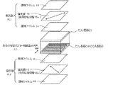
- FIG. 1 shows a schematic diagram of an example of the liquid crystal display device of the present invention.
- the liquid crystal display device shown in FIG. 1 has a structure in which a polymer stable blue phase liquid crystal display element LC is sandwiched between two polarizing plates PL1 and PL2.
- the polarizing plate PL1 has a configuration in which the polarizing film 10 is sandwiched between two transparent films 14 and 18, and the polarizing plate PL2 has a configuration in which the polarizing film 12 is sandwiched between two transparent films 16 and 20. ing.
- the transparent films 14 and 16 on the polymer stable blue phase liquid crystal display element LC side affect the display performance, but the transparent film on the opposite side of the polymer stable blue phase liquid crystal display element 18 and 20 function as protective films for the polarizing films 10 and 12 and will not normally affect the display performance.
- a COA substrate 24 is disposed on one of a pair of substrates of a liquid crystal cell, and a counter substrate without a color filter layer is disposed on the other.
- of the transparent film 16 on the light source side is 20 nm or less, and
- the retardation of the transparent film 16 and preferably by controlling the wavelength dependence of Re and Rth, light leakage in the front direction during black display can be further reduced, and CR can be further improved. It is possible to reduce the tinting that occurs in the oblique direction. More specifically, the absolute value
- the transparent film 16 has a small wavelength dependency of Re and Rth, that is, it is preferable that the absolute values of Re and Rth satisfy the above conditions over the visible light region.
- the preferable wavelength dependence of Re and Rth is specifically that
- Re (400) of the transparent film 16 is preferably ⁇ 5 to 5 nm, and Rth (400) is more preferably ⁇ 10 to 10 nm.
- Re (700) of the transparent film 16 is preferably ⁇ 10 to 10 nm, and Rth (700) is more preferably ⁇ 10 to 10 nm.
- Display characteristics can be further improved by controlling the optical characteristics of the transparent film 14 disposed on the display surface side.
- a preferred example is an example in which the transparent film 14 also satisfies the optical characteristics required for the transparent film 16.
- Another preferred example is an example in which the transparent film 14 exhibits optical biaxiality.
- Re of the transparent film 14 is about 200 to 350 nm and Rth is about ⁇ 88 to 88 nm, more preferably, Re is about 250 to 300 nm and Rth is about ⁇ 45 to 45 nm.
- the transparent film 14 has a two-layer structure that optically exhibits biaxiality.
- one of the two sheets has a Re of the transparent film 14 of about 20 to 120 nm and an Rth of about 125 to 225 nm, more preferably an Re of about 40 to 100 nm and an Rth of about 145 to 205 nm.
- Re of the transparent film 14 is about ⁇ 30 to 30 nm and Rth is about 50 to 150 nm, more preferably, Re is about ⁇ 10 to 10 nm and Rth is about 80 to 120 nm.
- Another preferable example is an example in which the transparent film 14 is optically uniaxial.
- one of the two sheets has Re of the transparent film 14 of about 60 to 210 nm and Rth of about 30 to 105 nm, more preferably Re of about 110 to 160 nm and Rth of about 55 to 80 nm.
- Re of the transparent film 14 is about ⁇ 30 to 30 nm and Rth is about 70 to 170 nm, more preferably, Re is about ⁇ 10 to 10 nm and Rth is about 100 to 140 nm.
- the transparent films 18 and 20 which are protective films outside the polarizing plates PL1 and PL2 may further have a functional layer on the surface thereof.
- the transparent film 20 may have a functional film such as an antifouling film, an anti-reflection film, an anti-glare film, or an anti-static film on the surface on the backlight side. May have a functional film such as an antifouling film, an anti-reflection film, an anti-glare film, or an anti-static film on its surface.
- the liquid crystal display device of FIG. 1 includes a backlight unit (not shown) on the outer side of the back side polarizing plate (polarizing plate PL2 in FIG. 1).
- the light source in the backlight unit is preferably an LED light source, and more preferably a direct type LED light source. When the LED light source is used, the black transmittance is further lowered and the front CR is further improved.
- the liquid crystal cell LC is a liquid crystal cell in which a polymer stable blue phase liquid crystal material is enclosed between a pair of substrates 22 and 24 and an electric field is applied in parallel to the substrate surface. It is an element.
- the electric field is preferably applied by two comb-shaped electrodes that are mutually incorporated on one substrate surface. In practice, it is a practical method to turn on and off the electric field by TFT operation using one of the two electrodes as a source electrode of a thin film transistor (TFT) and the other as a common electrode. That is, this electric field is preferably applied between the TFT electrode and the common electrode as an electric field corresponding to an input signal by incorporating the TFT and the common electrode in one substrate surface and turning on and off the TFT.
- TFT thin film transistor
- the substrate 24 arranged on the light source side is a color filter on array substrate, and although omitted in the drawing, has a color filter layer on the TFT array.
- the thickness of the color filter layer is thicker than that of the conventional color film layer (about 1 to 2 ⁇ m) and is generally about 2 to 4 ⁇ m. This is to suppress parasitic capacitance generated between the end of the pixel electrode and the wiring.
- the color filter layer included in the liquid crystal display device of the present invention preferably has a thickness of about 2 to 4 ⁇ m, but is not limited to this range.
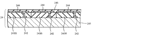
- FIG. 2 is a schematic cross-sectional view of an example of the COA substrate 24 in FIG.
- the COA substrate 24 shown in FIG. 2 includes a light-transmissive insulating substrate 241 such as a glass substrate, and a switching element 242 disposed for each pixel in a region corresponding to an active area on the insulating substrate 241.
- the color filter layers 243R, 243G, and 243B are provided.
- the color filter layers 243R, 243G, and 243B include a plurality of colored layers that are colored red (R), green (G), and blue (B), respectively, and emit light of each color component of red, green, and blue, respectively.
- R red
- G green
- B blue
- the COA substrate further includes a pixel electrode 244 made of a light-transmitting metal material such as ITO connected to the switching element 242. Further, the surfaces of these members are covered with an insulating layer 245 having a high dielectric constant and are flattened.
- an insulating layer 245 having a high dielectric constant and are flattened.
- JP-A 2007-240544, JP-A 2004-163979, JP-A 2008-15375 and the like can be referred to in addition to the above-mentioned Patent Documents 6 and 7.
- the position of the black matrix in the COA liquid crystal display device is preferably located on the COA substrate from the viewpoint of improving the degree of crosslinking of the polymer network. However, since the influence of the black matrix is small, it is disposed on the opposite glass substrate. It may be arranged at any position in the liquid crystal cell.
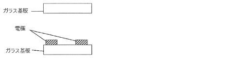
- FIG. 3 shows a schematic cross-sectional view of an example of the counter substrate 22 in FIG.
- the counter substrate 22 shown in FIG. 3 is made of an insulating substrate having a light transmission property such as a glass substrate, and there is no member that blocks light transmission, such as a color filter layer or an array member. Therefore, if ultraviolet rays are irradiated from the counter substrate 22 side during the formation of the polymer network, the crosslinking reaction can be sufficiently advanced, and the polymer network can be stably formed.
- the counter substrate 22 is not limited to the configuration shown in FIG. 3 and may have any configuration as long as the color filter layer and the array member are not disposed.
- the color filter needs to be arranged on the array substrate.
- the color filter that can be used in the present invention is a plurality of different colors (for example, three primary colors of red, green, and blue light, transparent, yellow, cyan, etc.) in the pixel portion of the substrate, as in the color filter of a normal liquid crystal display device. )
- a coloring material organic pigment, dye, carbon black, etc.
- a colored photosensitive composition which may be colorless
- a layer is formed by coating on a substrate, and a pattern is formed by photolithography.
- the spin coater method is employed in the initial stage, and the slit & spin type coater method is employed from the viewpoint of liquid saving.
- the slit coater method is generally adopted.
- Other methods include roll coating, bar coating, and die coating.
- a pixel color is also formed by an inkjet method.
- methods using a combination of a colored non-photosensitive composition and a photosensitive positive resist, a printing method, an electrodeposition method, and a film transfer method are known.
- the color filter used in the present invention may be produced by any method.
- the material for forming the color filter there are no particular restrictions on the material for forming the color filter.
- the coloring material any of dyes, organic pigments, inorganic pigments and the like can be used. Dyes have been studied due to the demand for higher CR, but in recent years, organic pigment dispersion technology has advanced, and breakdown pigments that have been finely crushed by the salt milling method, etc., and finer pigments by the build-up method have been high. Used for CR conversion. Any coloring material may be used in the present invention. As described above, the color sequential filter is not required in the field sequential drive mode.
- a transparent substrate is preferable, and glass, plastic film, optical crystal, or the like can be used.
- the distance between the pair of substrates is usually about 2 to 100 ⁇ m.
- the applied electric field is usually about 1000 to 100,000 V / cm.
- the electric field may be substantially parallel to the substrate (or perpendicular to the display direction).
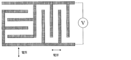
- There is no particular limitation on the method of applying the electric field but a structure in which two comb-shaped electrodes are mutually incorporated on one substrate surface is simple.
- the number of comb teeth per comb-shaped electrode is preferably about 2 to 100, the length is about 1 to 10,000 ⁇ m, the width is about 1 to 50 ⁇ m, and the distance between comb teeth is about 1 to 100 ⁇ m.
- two comb-shaped electrodes are attached to the substrate so as to be mutually incorporated in the same plane, and by applying a voltage to them, an electric field is applied perpendicular to the comb teeth and parallel to the substrate surface.
- the other substrate is a glass plate without electrodes, and is placed opposite to each other through a spacer such as a thin film.
- a gap with a spacer thickness is formed between the pair of substrates, and the liquid crystal display element LC can be manufactured by injecting a liquid crystal material into the gap.
- the liquid crystal cell LC is arranged between two polarizing plates PL1 and PL2, the absorption axes 10a and 12a of the polarizing plates PL1 and PL2 are orthogonal to each other (so-called crossed Nicols state), and the electric field direction is relative to each absorption axis. If the angle is 45 °, the transmittance is zero when the electric field is zero (because the retardation is zero), and the light is transmitted when the electric field is applied (because the cell in which retardation occurs acts like a wave plate). Therefore, a bright-dark CR can be applied with the voltage ON-OFF. When the retardation of the liquid crystal display element is half of the wavelength of transmitted light, the transmittance is maximized.
- the direction of the long side of the comb electrode of the liquid crystal display element LC is 45 degrees with the absorption axes 10a and 12a of the polarizing plates PL1 and PL2, so that the retardation efficiency is maximized. .
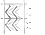
- the configuration of the electrode is two domains in the right half and the left half, and in FIG. 8 described later, two domains can be obtained using a zigzag comb-shaped electrode.
- the electrode structure used in the present invention is not particularly limited as long as it is an electrode structure capable of coplanar switching.
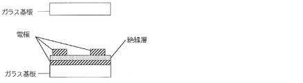
- the electrode structure is such that the common electrode and the pixel electrode are both comb-teeth electrodes, the common electrode and the comb of the surface electrode as shown in the cross-sectional view of FIG.
- An electrode structure in which an insulating layer is sandwiched between the pixel electrode of the tooth electrode may be used.
- FIG. 7A is a cross-sectional view schematically showing a schematic configuration of a main part of the display element according to the present embodiment in an electric field non-application state (OFF state), and FIG. It is sectional drawing which shows typically schematic structure of the principal part of the display element concerning this Embodiment in an ON state.
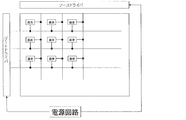
- FIG. 7 is a block diagram showing an example of a schematic configuration of a main part of the display device using the display element according to the present embodiment.
- the display element according to this embodiment is used in a display device together with a drive circuit.
- FIG. 8 includes a display element in which pixels are arranged in a matrix, a source driver and a gate driver as drive circuits, a power supply circuit, and the like.
- the display element is provided with a plurality of data signal lines and a plurality of scanning signal lines intersecting with the data signal lines, and the pixel is provided for each combination of the data signal lines and the scanning signal lines. It has been.
- the power supply circuit supplies a voltage for performing display on the display element to the source driver and the gate driver, whereby the source driver drives a data signal line of the display element, and the gate driver The scanning signal line of the display element is driven.
- a switching element (not shown) is provided.
- the switching element for example, an FET (field effect transistor) or a TFT (thin film transistor) is used, and the gate electrode of the switching element is a scanning signal line, the source electrode is a data signal line, and the drain electrode is It is connected to a pixel electrode (not shown).
- the switching element is turned on, and the signal voltage determined based on the display data signal input from the controller (not shown) is applied to the data signal line by the source driver.
- the display element ideally continues to hold the voltage at the time of interruption while the selection period of the scanning signal line ends and the switching element is interrupted.
- the display element is optically isotropic (macroscopic, specifically, a visible light wavelength region, that is, a wavelength of visible light) when an electric field (voltage) is applied or no electric field (voltage) is applied.
- Display is performed using a medium (a liquid crystalline medium (liquid crystal material), a dielectric substance) indicating a scale or a larger scale.
- the display element shown in FIGS. 7A and 7B includes a pair of substrates disposed as opposed to each other as medium holding means (optical modulation layer holding means), and an optical modulation layer between the pair of substrates. And a medium layer composed of a medium that is optically modulated by application of an electric field (hereinafter referred to as medium A) is sandwiched between the outside of the pair of substrates, that is, the surface opposite to the opposing surfaces of the two substrates.
- the polarizing plate is provided with a polarizing plate.
- At least one substrate has a light-transmitting property, for example, a transparent substrate such as a glass substrate.
- a transparent substrate such as a glass substrate.
- a comb-like comb-like electrode which is an electric field applying means (electric field applying member) for applying an electric field (lateral electric field) substantially parallel to the substrate 1 to the medium layer.
- the comb-tooth portions (comb-tooth electrodes) of the comb-tooth electrodes are disposed so as to face each other.
- zigzag comb electrodes are arranged to face each other.
- the comb electrode is made of an electrode material such as a transparent electrode material such as ITO (indium tin oxide), and is set to have a line width of 5 ⁇ m, a distance between electrodes (electrode interval) of 5 ⁇ m, and a thickness of 0.3 ⁇ m.
- ITO indium tin oxide
- the electrode material, the line width, the distance between the electrodes, and the thickness are merely examples, and are not limited thereto.
- the liquid crystal layer is formed by bonding the substrate provided with the comb electrodes with a sealing agent (not shown) through a spacer such as a plastic bead or a glass fiber spacer (not shown) as necessary. .
- the liquid crystal used in this embodiment is a medium whose degree of optical anisotropy changes when an electric field is applied.
- E j an electric field
- the conventional liquid crystal display element performs display using only the change in the alignment direction due to the rotation of the liquid crystal molecules accompanying the application of an electric field, and the liquid crystal molecules are aligned in a certain direction. Therefore, the inherent viscosity of the liquid crystal greatly affects the response speed.
- the liquid crystal display device of the present embodiment performs display using a change in the degree of optical anisotropy in the medium. Therefore, unlike the conventional liquid crystal display element, there is no problem that the inherent viscosity of the liquid crystal greatly affects the response speed, so that a high-speed response can be realized. Moreover, since it is a high-speed response, it is also preferable to use a field sequential color drive system.
- the field sequential drive method is described in detail in JP-A-2005-181667, JP-A-2009-42446, JP-A-2007-322988, and JP-A-3996178, and can be referred to. .
- a backlight unit that sequentially emits independent three primary color lights is used.
- a backlight unit including an LED as the light source is preferable.
- a backlight unit including an LED element that emits three colors of red, green, and blue as the light source is preferably used.
- the 1st and 2nd transparent films (in FIG. 1, the transparent film 16 and the transparent film 14) used for the liquid crystal display device of this invention are demonstrated.
- the first and second transparent films preferably function as a protective film for the polarizing plate from the viewpoint of thinning the liquid crystal display device. Therefore, polymer films made of various materials used as protective films for polarizing plates can be used.
- the cellulose acylate film has good suitability for polarizing plate processing and is suitable for use as the first and second transparent films. Further, by adding a retardation reducing agent to be described later, a cellulose acylate film satisfying the characteristics required for the first transparent film, that is, low Re and low Rth can be produced. Further, by adding a wavelength dispersion adjusting agent, Re and Rth have appropriate wavelength dispersion characteristics, specifically,
- cellulose as a cellulose acylate raw material examples include cotton linter and wood pulp (hardwood pulp, softwood pulp), and any cellulose acylate obtained from any raw material cellulose may be used. .
- Detailed descriptions of these raw material celluloses can be found, for example, in the course of plastic materials (17) Fibrous resin (by Marusawa and Uda, published by Nikkan Kogyo Shimbun, 1970) and JIII Journal of Technical Disclosure 2001-1745 (page 7). To page 8) can be used, but is not limited thereto.
- Cellulose acylate is an acylated hydroxyl group of cellulose.
- the acyl group may be any acyl group having 2 to 22 carbon atoms.
- the degree of substitution with a hydroxyl group in cellulose is not particularly limited, but the degree of substitution can be obtained by measuring the degree of binding of acetic acid and / or a fatty acid having 3 to 22 carbon atoms to substitute for the hydroxyl group of cellulose. As a measuring method, it can be carried out according to ASTM D-817-91.
- the degree of substitution of the cellulose with a hydroxyl group is not particularly limited, but the degree of acyl substitution with the hydroxyl group of cellulose is preferably 2.00 to 3.00. Furthermore, the substitution degree is more preferably 2.75 to 3.00, and further preferably 2.85 to 3.00.
- the acyl group having 2 to 22 carbon atoms may be an aliphatic group or an allyl group, and may be a single type or a mixture of two or more types. Good. Examples thereof include cellulose alkylcarbonyl ester, alkenylcarbonyl ester, aromatic carbonyl ester and aromatic alkylcarbonyl ester. Each of these may further have a substituted group.
- acyl groups acetyl group, propionyl group, butanoyl group, heptanoyl group, hexanoyl group, octanoyl group, decanoyl group, dodecanoyl group, tridecanoyl group, tetradecanoyl group, hexadecanoyl group, octadecanoyl group And iso-butanoyl group, tert-butanoyl group, cyclohexanecarbonyl group, oleoyl group, benzoyl group, naphthylcarbonyl group, cinnamoyl group and the like.
- acetyl group, propionyl group, butanoyl group, dodecanoyl group, octadecanoyl group, tert-butanoyl group, oleoyl group, benzoyl group, naphthylcarbonyl group, cinnamoyl group and the like are preferable, and acetyl group, propionyl group, butanoyl group are preferable. Groups are more preferred.
- the total substitution degree is 2.50 to 3.00
- the optical anisotropy of the cellulose acylate film can be reduced. Therefore, for the production of the cellulose acylate film used as the first transparent film, it is preferable to use cellulose acylate having an acyl substitution degree of 2.60 to 3.00 as a raw material, and an acyl substitution degree of 2.65 to More preferably, 3.00 cellulose acylate is used.
- the type of the substituent that the cellulose acylate used as the raw material of the cellulose acylate film used as the second transparent film has and the degree of substitution will be determined according to the required optical properties.
- cellulose acylate containing an aromatic group such as a phenyl group can be used.
- the degree of polymerization of cellulose acylate is preferably 180 to 700 in terms of viscosity average degree of polymerization, more preferably 180 to 550, more preferably 180 to 400, and particularly preferably 180 to 350 for cellulose acetate.
- the degree of polymerization can be measured, for example, by the intrinsic viscosity method of Uda et al.
- Mw is a mass average molecular weight
- Mn is a number average molecular weight
- the specific value of Mw / Mn is preferably 1.0 to 3.0, more preferably 1.0 to 2.0, and more preferably 1.0 to 1.6. Further preferred.
- the average molecular weight (polymerization degree) increases, but the viscosity is lower than that of normal cellulose acylate, which is useful.
- Cellulose acylate having a small amount of low molecular components can be obtained by removing low molecular components from cellulose acylate synthesized by a usual method. The removal of the low molecular component can be carried out by washing the cellulose acylate with an appropriate organic solvent.
- the amount of sulfuric acid catalyst in the acetylation reaction is preferably adjusted to 0.5 to 25 parts by mass with respect to 100 parts by mass of cellulose.
- cellulose acylate that is preferable in terms of molecular weight distribution (uniform molecular weight distribution) can be synthesized.
- the water content is preferably 2% by mass or less, more preferably 1% by mass or less, and particularly 0.7% by mass. It is a cellulose acylate having a moisture content of not more than%.
- cellulose acylate contains water and is known to be 2.5 to 5% by mass. In order to make the moisture content of a cellulose acylate into the said range, it is necessary to dry, and the method will not be specifically limited if it becomes the target moisture content.
- Cellulose acylate is described in detail on pages 7 to 12 of the raw material cotton and the synthesis method in the Japan Society for Invention and Technology (Publication No. 2001-1745, published on March 15, 2001, Japan Society for Invention). .
- a single or a mixture of two or more different cellulose acylates can be used.
- cellulose acylate film select from various additives (for example, compounds that reduce optical anisotropy, wavelength dispersion adjusters, UV inhibitors, plasticizers, deterioration inhibitors, fine particles, optical property adjusters, etc.) At least one of the above can be added.
- compounds that reduce optical anisotropy include compounds that satisfy the following formula.
- Rth (A) represents Rth (nm) of a film containing A% of a compound that decreases optical anisotropy
- Rth (0) is the film, and decreases optical anisotropy.
- Rth (nm) of a film not containing a compound is represented, and A represents the mass (%) of a compound that reduces optical anisotropy when the mass of the film raw material polymer is 100.
- the compound that reduces the optical anisotropy more preferably satisfies the following formula. (Rth (A) ⁇ Rth (0) ) /A ⁇ 2.0 0.1 ⁇ A ⁇ 20
- the compound that lowers the optical anisotropy is preferably selected from compounds that are sufficiently compatible with cellulose acylate and do not have a rod-like structure or planar structure. Specifically, when having a plurality of planar functional groups such as aromatic groups, a compound having a structure in which these functional groups are not on the same plane but on a non-planar surface is preferable.
- the optical anisotropy is reduced by suppressing the cellulose acylate in the film from being oriented in the plane and in the film thickness direction as described above.
- compounds having an octanol-water partition coefficient (log P value) of 0 to 7 are preferably used.
- a compound having a log P value of 7 or less compatibility with cellulose acylate is improved, and the cloudiness and powder blowing of the film can be more effectively prevented.
- the hydrophilicity is high by adopting a compound having a log P value of 0 or more, it is possible to more effectively prevent the water resistance of the cellulose acetate film from deteriorating.
- a more preferable range of the logP value is 1 to 6, and a particularly preferable range is 1.5 to 5.
- the octanol-water partition coefficient (log P value) can be measured by a flask immersion method described in JIS Japanese Industrial Standard Z7260-107 (2000).
- the octanol-water partition coefficient (log P value) can be estimated by a computational chemical method or an empirical method instead of the actual measurement.
- Crippen's fragmentation method J. Chem. Inf. Comput. Sci., 27, 21 (1987).
- Viswanadhan's fragmentation method J. Chem. Inf. Comput. Sci., 29, 163 (1989).
- Broto's fragmentation method Eur. J. Med. Chem.-Chim. Theor., 19, 71 (1984).
- Crippen's fragmentation method J. Chem. Inf. Comput. Sci., 27 , 21 (1987).
- the log P value of a certain compound varies depending on the measurement method or calculation method, it is preferable to determine whether or not the compound is within the scope of the present invention by the Crippen's fragmentation method.
- the compound that reduces optical anisotropy may or may not contain an aromatic group.
- the compound that reduces optical anisotropy preferably has a molecular weight of 150 to 3000, more preferably 170 to 2000, and even more preferably 200 to 1000. As long as these molecular weights are within the range, a specific monomer structure may be used, or an oligomer structure or a polymer structure in which a plurality of the monomer units are bonded may be used.
- the compound that reduces optical anisotropy is preferably a liquid at a temperature of 25 ° C. or a solid having a melting point of 25 to 250 ° C., more preferably a liquid at a temperature of 25 ° C. or a melting point of 25 to 25 ° C.
- the compound which reduces optical anisotropy does not volatilize in the process of dope casting for cellulose acylate film production and drying.
- the amount of the compound that decreases the optical anisotropy is preferably 0.01 to 30% by mass, more preferably 1 to 25% by mass, and more preferably 5 to 20% by mass of the cellulose acylate. Is particularly preferred.
- the compound that decreases the optical anisotropy may be used alone, or two or more compounds may be mixed and used in an arbitrary ratio.
- the timing for adding the compound for reducing the optical anisotropy may be any time during the dope preparation process, or may be performed at the end of the dope preparation process.
- the compound that reduces the optical anisotropy is such that the average content of the compound in the portion from the surface on at least one side to 10% of the total film thickness is the average content of the compound in the central portion of the cellulose acylate film. 80-99% of The amount of the compound that reduces the optical anisotropy can be determined by measuring the amount of the compound at the surface and in the central portion, for example, by a method using an infrared absorption spectrum described in JP-A-8-57879.
- a first example of a compound that reduces optical anisotropy is a compound represented by the following general formula (13).
- R 11 represents an alkyl group or an aryl group
- R 12 and R 13 each independently represent a hydrogen atom, an alkyl group, or an aryl group. Further, it is particularly preferable that the total number of carbon atoms of R 11 , R 12 and R 13 is 10 or more.
- R 11 , R 12 and R 13 may have a substituent, and the substituent is preferably a fluorine atom, an alkyl group, an aryl group, an alkoxy group, a sulfone group or a sulfonamide group, an alkyl group, an aryl group, Alkoxy groups, sulfone groups and sulfonamido groups are particularly preferred.
- the alkyl group may be linear, branched or cyclic, and preferably has 1 to 25 carbon atoms, more preferably 6 to 25, and more preferably 6 to 20 (For example, methyl, ethyl, propyl, isopropyl, butyl, isobutyl, t-butyl, amyl, isoamyl, t-amyl, hexyl, cyclohexyl, heptyl, octyl, bicyclo Octyl, nonyl, adamantyl, decyl, t-octyl, undecyl, dodecyl, tridecyl, tetradecyl, pentadecyl, hexadecyl, heptadecyl, octadecyl, nonadecyl, didecyl) are particularly preferred .
- aryl group those having 6 to 30 carbon atoms are preferable, and those having 6 to 24 carbon atoms (for example, phenyl group, biphenyl group, terphenyl group, naphthyl group, binaphthyl group, triphenylphenyl group) are particularly preferable.
- phenyl group, biphenyl group, terphenyl group, naphthyl group, binaphthyl group, triphenylphenyl group are particularly preferable.
- Pr i means an isopropyl group (hereinafter the same).
- Examples of the compound that reduces the optical anisotropy include a compound represented by the following general formula (18).
- R 14 represents an alkyl group or an aryl group
- R 15 and R 16 each independently represent a hydrogen atom, an alkyl group, or an aryl group.
- R 14 is preferably a phenyl group or a cyclic alkyl group.
- R 15 and R 16 are each preferably a phenyl group or an alkyl group.
- As the alkyl group both a cyclic alkyl group and a linear alkyl group are preferable.
- These groups may have a substituent, and the substituent is preferably a fluorine atom, an alkyl group, an aryl group, an alkoxy group, a sulfone group, or a sulfonamide group, and an alkyl group, an aryl group, an alkoxy group, a sulfone group.
- Groups and sulfonamido groups are particularly preferred.
- the compound represented by the general formula (18) is more preferably a compound represented by the general formula (19).
- R 114 , R 115 and R 116 each independently represents an alkyl group or an aryl group.
- the alkyl group is preferably a cyclic alkyl group or a linear alkyl group
- the aryl group is preferably a phenyl group.
- Bu i means an isobutyl group.
- wavelength dispersion adjusting agent a compound that lowers the wavelength dispersion of retardation
- ⁇ Rth
- ⁇ Rth (B) means ⁇ Rth of the film containing B mass% of the wavelength dispersion adjusting agent
- ⁇ Rth (0) is the wavelength dispersion adjustment. It means ⁇ Rth of the same film containing no agent.
- the wavelength dispersion adjusting agent satisfies the following formula. ( ⁇ Rth (B) ⁇ Rth (0)) / B ⁇ ⁇ 3.0 0.05 ⁇ B ⁇ 25 Further, it is more preferable that the wavelength dispersion adjusting agent satisfies the following formula. ( ⁇ Rth (B) ⁇ Rth (0)) / B ⁇ ⁇ 4.0 0.1 ⁇ B ⁇ 20
- the above-mentioned wavelength dispersion adjusting agent is a compound having absorption in the ultraviolet region of 200 to 400 nm and capable of reducing
- the Re and Rth values of the cellulose acylate film generally have wavelength dispersion characteristics that are larger on the long wavelength side than on the short wavelength side. Accordingly, it is required to make the wavelength dispersion smooth by increasing Re and Rth on the relatively small short wavelength side.
- a compound having absorption in the ultraviolet region with a wavelength of 200 to 400 nm has a wavelength dispersion characteristic that the absorbance on the long wavelength side is larger than that on the short wavelength side. If this compound itself is isotropically present inside the cellulose acylate film, it is assumed that the birefringence of the compound itself, and thus the wavelength dispersion of Re and Rth, is large on the short wavelength side as well as the wavelength dispersion of absorbance.
- Re and Rth of the cellulose acylate film are used.
- the compound used as the wavelength dispersion adjusting agent is required to be sufficiently uniformly compatible with cellulose acylate.
- the absorption band range in the ultraviolet region of such a compound is preferably 200 to 400 nm, more preferably 220 to 395 nm, and further preferably 240 to 390 nm.
- the compound used as the wavelength dispersion adjusting agent is required not to increase the spectral transmittance of the cellulose acylate film.
- the cellulose acylate film used as a transparent film in the present invention preferably has a spectral transmittance of 45% to 95% at a wavelength of 380 nm, and preferably has a spectral transmittance of 10% or less at a wavelength of 350 nm.
- the chromatic dispersion adjusting agent is preferably not volatilized in the dope casting and drying processes.
- the wavelength dispersion adjusting agent preferably has a molecular weight of 250 to 1000, more preferably 260 to 800, still more preferably 270 to 800, and particularly preferably 300 to 800.
- a specific monomer structure may be used as long as these molecular weights are within the range, and an oligomer structure or a polymer structure in which a plurality of the monomer units are bonded may be used.
- the addition amount of the wavelength dispersion adjusting agent is preferably 0.01 to 30% by mass, more preferably 0.1 to 20% by mass, and more preferably 0.2 to 10% by mass with respect to cellulose acylate. % Is particularly preferred.
- These wavelength dispersion adjusting agents may be used alone or in combination of two or more compounds at an arbitrary ratio.
- the timing for adding these wavelength dispersion adjusting agents may be any time during the dope production process, or at the end of the dope preparation process. Good.
- wavelength dispersion adjusting agent examples include, but are not limited to, benzotriazole compounds, benzophenone compounds, compounds containing a cyano group, oxybenzophenone compounds, salicylic acid ester compounds, nickel complex compounds, and the like. It is not something.
- Q 11 represents a nitrogen-containing aromatic heterocycle, preferably a 5- to 7-membered nitrogen-containing aromatic heterocycle, more preferably a 5- or 6-membered nitrogen-containing aromatic heterocycle, , Imidazole ring, pyrazole ring, triazole ring, tetrazole ring, thiazole ring, oxazole ring, selenazole ring, benzotriazole ring, benzothiazole ring, benzoxazole ring, benzoselenazole ring, thiadiazole ring, oxadiazole ring, naphthothiazole ring Naphthoxazole ring, azabenzimidazole ring, purine ring, pyridine ring, pyrazine ring, pyrimidine ring, pyridazine ring, triazine ring, triazaindene ring, tetrazaindene ring, and the like, more preferably a
- Nitrogen-containing aromatic heterocycle specifically imidazole ring, pyrazo Le ring, triazole ring, tetrazole ring, thiazole ring, oxazole ring, benzotriazole ring, benzothiazole ring, benzoxazole ring, thiadiazole ring, oxadiazole ring are preferred, particularly preferably a benzotriazole ring.
- the aromatic ring represented by Q 12 may be an aromatic hydrocarbon ring or an aromatic heterocycle. These may be monocyclic or may form a condensed ring with another ring.
- the aromatic hydrocarbon ring is preferably a monocyclic or bicyclic aromatic hydrocarbon ring having 6 to 30 carbon atoms, more preferably a monocyclic or bicyclic aromatic hydrocarbon ring having 6 to 20 carbon atoms. More preferably a monocyclic or bicyclic aromatic hydrocarbon ring having 6 to 12 carbon atoms, and most preferably a benzene ring.
- the aromatic heterocycle is preferably an aromatic heterocycle containing a nitrogen atom or a sulfur atom.
- hetero ring examples include, for example, thiophene ring, imidazole ring, pyrazole ring, pyridine ring, pyrazine ring, pyridazine ring, triazole ring, triazine ring, indole ring, indazole ring, purine ring, thiazoline ring, thiazole ring, thiadiazole.
- the aromatic hetero ring is preferably a pyridine ring, a triazine ring or a quinoline ring.
- the aromatic ring represented by Q 12 is preferably an aromatic hydrocarbon ring, more preferably a naphthalene ring or a benzene ring, and particularly preferably a benzene ring.
- Q 11 and Q 12 may each have a substituent, and the substituent T described below is preferable as the substituent.
- the substituent T include an alkyl group (preferably having 1 to 20 carbon atoms, more preferably 1 to 12 carbon atoms, and particularly preferably 1 to 8 carbon atoms.
- a group (preferably having 6 to 30 carbon atoms, more preferably 6 to 20 carbon atoms, particularly preferably 6 to 12 carbon atoms, and examples thereof include a phenyl group, a p-methylphenyl group, and a naphthyl group), Or an unsubstituted amino group (preferably having 0 to 20 carbon atoms, more preferably 0 to 10 carbon atoms, particularly preferably 0 to 6 carbon atoms, such as an amino group, a methylamino group, a dimethylamino group, a diethylamino group, Dibenzylamino group, etc.), alkoxy groups (preferably having 1 to 20 carbon atoms, more preferably 1 to 12 carbon atoms, particularly preferably 1 to 8 carbon atoms, such as methoxy group, ethoxy group, butoxy group) Groups), aryloxy groups (preferably having 6 to 20 carbon atoms, more preferably 6 to 16 carbon atoms, and particularly preferably 6 to 12 carbon atoms
- a phenyloxy group, a 2-naphthyloxy group, etc. an acyl group (preferably having 1 to 20 carbon atoms, more preferably 1 to 16 carbon atoms, particularly preferably 1 to 12 carbon atoms, Acetyl group, benzoyl group, formyl group, pivaloyl group, etc.), alkoxycarbonyl group (preferably having 2 to 20 carbon atoms, more preferably 2 to 16 carbon atoms, particularly preferably 2 to 12 carbon atoms)
- an aryloxycarbonyl group preferably having a carbon number of 7 to 20, more preferably a carbon number of 7 to 16, particularly preferably a carbon number of 7 to 10, such as phenyl Oxycarbonyl group, etc.
- acyloxy group preferably having 2 to 20 carbon atoms, more preferably carbon It has a prime number of 2 to 16, particularly preferably 2 to 10 carbon
- An acylamino group (preferably having 2 to 20 carbon atoms, more preferably 2 to 16 carbon atoms, particularly preferably 2 to 10 carbon atoms, such as acetylamino group and benzoylamino group), alkoxycarbonyl
- An amino group (preferably having 2 to 20 carbon atoms, more preferably 2 to 16 carbon atoms, particularly preferably 2 to 12 carbon atoms, such as a methoxycarbonylamino group), an aryloxycarbonylamino group (preferably Has 7 to 20 carbon atoms, more preferably 7 to 16 carbon atoms, particularly preferably 7 to 12 carbon atoms, such as a phenyloxycarbonylamino group, and a sulfonylamino group (preferably 1 to 1 carbon atom).
- sulfamoyl group (preferably having 0 to 20 carbon atoms, more preferably 0 to 16 carbon atoms, particularly preferably 0 to 12 carbon atoms, such as sulfamoyl group, methyl A sulfamoyl group, a dimethylsulfamoyl group, a phenylsulfamoyl group, etc.), a carbamoyl group (preferably having 1 to 20 carbon atoms, more preferably 1 to 16 carbon atoms, and particularly preferably 1 to carbon atoms).
- Examples thereof include a carbamoyl group, a methylcarbamoyl group, a diethylcarbamoyl group, a phenylcarbamoyl group, etc.), an alkylthio group (preferably having 1 to 20 carbon atoms, more preferably 1 to 16 carbon atoms, and particularly preferably carbon atoms). And examples thereof include a methylthio group and an ethylthio group.
- An arylthio group (preferably having 6 to 20 carbon atoms, more preferably 6 to 16 carbon atoms, particularly preferably 6 to 12 carbon atoms, such as a phenylthio group), a sulfonyl group (preferably 1 to 20 carbon atoms, more preferably 1 to 16 carbon atoms, particularly preferably 1 to 12 carbon atoms, such as mesyl group and tosyl group), sulfinyl group (preferably 1 to 20 carbon atoms, More preferably, it has 1 to 16 carbon atoms, particularly preferably 1 to 12 carbon atoms, such as methanesulfinyl group, benzenesulfinyl group, etc.), ureido group (preferably 1 to 20 carbon atoms, more preferably carbon The number is 1 to 16, particularly preferably 1 to 12, and examples thereof include a ureido group, a methylureido group, and a phenylureido group.
- Phosphoric acid amide groups preferably having 1 to 20 carbon atoms, more preferably 1 to 16 carbon atoms, particularly preferably 1 to 12 carbon atoms, and examples thereof include diethyl phosphoric acid amide and phenyl phosphoric acid amide.
- halogen atom eg fluorine atom, chlorine atom, bromine atom, iodine atom
- cyano group eg fluorine
- a silyl group (preferably having 3 to 40 carbon atoms, more preferably 3 to 30 carbon atoms, particularly preferably 3 to 24 carbon atoms, and examples thereof include a trimethylsilyl group and a triphenylsilyl group. ) And the like. These substituents may be further substituted. Moreover, when there are two or more substituents, they may be the same or different. If possible, they may be linked together to form a ring.
- the compounds represented by the general formula (101) are preferable.
- R 1 , R 2 , R 3 , R 4 , R 5 , R 6 , R 7 and R 8 each independently represents a hydrogen atom or a substituent.
- R 1 , R 2 , R 3 , R 4 , R 5 , R 6 , R 7 , R 8 , and R 9 each independently represent a hydrogen atom or a substituent, and the above-mentioned substituent T is applied as the substituent. it can. These substituents may be further substituted with another substituent, and the substituents may be condensed to form a ring structure.
- R 1 and R 3 are each preferably a hydrogen atom, an alkyl group, an alkenyl group, an alkynyl group, an aryl group, an amino group, an alkoxy group, an aryloxy group, a hydroxy group, or a halogen atom, more preferably a hydrogen atom.
- An alkyl group, an aryl group, an alkyloxy group, an aryloxy group and a halogen atom more preferably a hydrogen atom and an alkyl group having 1 to 12 carbon atoms, particularly preferably an alkyl group having 1 to 12 carbon atoms (preferably a carbon atom). 4 to 12).
- R 2 and R 4 are each preferably a hydrogen atom, an alkyl group, an alkenyl group, an alkynyl group, an aryl group, an amino group, an alkoxy group, an aryloxy group, a hydroxy group, or a halogen atom, more preferably a hydrogen atom.
- An alkyl group, an aryl group, an alkyloxy group, an aryloxy group, and a halogen atom more preferably a hydrogen atom and an alkyl group having 1 to 12 carbon atoms, particularly preferably a hydrogen atom and a methyl group, and most preferably a hydrogen atom. Is an atom.
- R 5 and R 8 are each preferably a hydrogen atom, an alkyl group, an alkenyl group, an alkynyl group, an aryl group, an amino group, an alkoxy group, an aryloxy group, a hydroxy group, or a halogen atom, more preferably a hydrogen atom.
- An alkyl group, an aryl group, an alkyloxy group, an aryloxy group, and a halogen atom more preferably a hydrogen atom and an alkyl group having 1 to 12 carbon atoms, particularly preferably a hydrogen atom and a methyl group, and most preferably a hydrogen atom. Is an atom.
- R 6 and R 7 are each preferably a hydrogen atom, an alkyl group, an alkenyl group, an alkynyl group, an aryl group, an amino group, an alkoxy group, an aryloxy group, a hydroxy group, or a halogen atom, more preferably a hydrogen atom.
- An alkyl group, an aryl group, an alkyloxy group, an aryloxy group and a halogen atom more preferably a hydrogen atom and a halogen atom, and particularly preferably a hydrogen atom and a chlorine atom.
- the compounds represented by the general formula (101) are preferable.
- R 1 , R 3 , R 6 and R 7 have the same meanings as those in formula (101-A), respectively, and the preferred ranges are also the same.
- examples of the benzophenone-based compound that can be used as the wavelength dispersion adjusting agent include a compound represented by the general formula (102).
- Q 1 and Q 2 each represent an aromatic ring.
- X represents NR (R represents a hydrogen atom or a substituent), an oxygen atom, or a sulfur atom.
- the aromatic ring represented by Q 1 or Q 2 may be an aromatic hydrocarbon ring or an aromatic heterocycle. These may be monocyclic or may form a condensed ring with another ring.
- the aromatic hydrocarbon ring represented by Q 1 and Q 2 is preferably (preferably a monocyclic or bicyclic aromatic hydrocarbon ring having 6 to 30 carbon atoms (for example, a benzene ring, a naphthalene ring, etc.). More preferably, it is an aromatic hydrocarbon ring having 6 to 20 carbon atoms, and further preferably an aromatic hydrocarbon ring having 6 to 12 carbon atoms.) More preferably, it is a benzene ring.
- the aromatic heterocycle represented by Q 1 and Q 2 is preferably an aromatic heterocycle containing at least one of an oxygen atom, a nitrogen atom or a sulfur atom.
- the heterocyclic ring include, for example, furan ring, pyrrole ring, thiophene ring, imidazole ring, pyrazole ring, pyridine ring, pyrazine ring, pyridazine ring, triazole ring, triazine ring, indole ring, indazole ring, purine ring, thiazoline.
- the aromatic hetero ring is preferably a pyridine ring, a triazine ring or a quinoline ring.
- the aromatic ring represented by Q 1 or Q 2 is preferably an aromatic hydrocarbon ring, more preferably an aromatic hydrocarbon ring having 6 to 10 carbon atoms, and further preferably a substituted or unsubstituted benzene. It is a ring.
- Q 1 or Q 2 may further have a substituent, and the above-described substituent T is preferable, but the substituent does not contain a carboxylic acid, a sulfonic acid, or a quaternary ammonium salt. Further, if possible, substituents may be linked to form a ring structure.
- X represents NR (R represents a hydrogen atom or a substituent.
- substituent the above-mentioned substituent T can be applied
- an oxygen atom or a sulfur atom X is preferably NR (R is preferably an acyl group) , A sulfonyl group, and these substituents may be further substituted.)
- an oxygen atom particularly preferably an oxygen atom.
- R 21 , R 22 , R 23 , R 24 , R 25 , R 26 , R 27 , R 28 , and R 29 each independently represent a hydrogen atom or a substituent.
- R 21 , R 23 , R 24 , R 25 , R 26 , R 28 , and R 29 each independently represent a hydrogen atom or a substituent, and the substituent T described above can be applied as the substituent. These substituents may be further substituted with another substituent, and the substituents may be condensed to form a ring structure.
- R 21 , R 23 , R 24 , R 25 , R 26 , R 28 , and R 29 are preferably a hydrogen atom, alkyl group, alkenyl group, alkynyl group, aryl group, amino group, alkoxy group, aryloxy group , A hydroxy group, and a halogen atom, more preferably a hydrogen atom, an alkyl group, an aryl group, an alkyloxy group, an aryloxy group, and a halogen atom, still more preferably a hydrogen atom and a carbon 1-12 alkyl group, Preferred are a hydrogen atom and a methyl group, and most preferred is a hydrogen atom.
- R 22 is preferably a hydrogen atom, an alkyl group, an alkenyl group, an alkynyl group, an aryl group, an amino group, an alkoxy group, an aryloxy group, a hydroxy group, or a halogen atom, more preferably a hydrogen atom or a carbon number of 1 to 20
- R 27 is preferably a hydrogen atom, an alkyl group, an alkenyl group, an alkynyl group, an aryl group, an amino group, an alkoxy group, an aryloxy group, a hydroxy group, a halogen atom, more preferably a hydrogen atom or an alkyl group having 1 to 20 carbon atoms.
- R 10 represents a hydrogen atom, an alkyl group, an alkenyl group, an alkynyl group, or an aryl group.
- R 10 represents a hydrogen atom, an alkyl group, an alkenyl group, an alkynyl group, or an aryl group, and these may have a substituent.
- substituent the above-described substituent T can be applied.
- R 10 is preferably an alkyl group, more preferably an alkyl group having 5 to 20 carbon atoms, and still more preferably an alkyl group having 5 to 12 carbon atoms (n-hexyl group, 2-ethylhexyl group, n-octyl group).
- n-decyl group, n-dodecyl group, benzyl group, etc. particularly preferably a substituted or unsubstituted alkyl group having 6 to 12 carbon atoms (2-ethylhexyl group, n-octyl group). N-decyl group, n-dodecyl group, benzyl group).
- the compound represented by the general formula (102) can be synthesized by a known method described in JP-A-11-12219. Specific examples of the compound represented by the general formula (102) are given below, but the present invention is not limited to the following specific examples.
- examples of the compound containing a cyano group that can be used as the wavelength dispersion adjusting agent used in the present invention include a compound represented by the general formula (103).
- Q 31 and Q 32 each independently represents an aromatic ring.
- X 31 and X 32 each represent a hydrogen atom or a substituent, and at least one of them represents a cyano group, a carbonyl group, a sulfonyl group, or an aromatic heterocycle.
- the aromatic ring represented by Q 31 and Q 32 may be an aromatic hydrocarbon ring or an aromatic heterocycle. These may be monocyclic or may form a condensed ring with another ring.
- the aromatic hydrocarbon ring is preferably a monocyclic or bicyclic aromatic hydrocarbon ring having 6 to 30 carbon atoms (for example, benzene ring, naphthalene ring, etc.), more preferably 6 to 20 carbon atoms.
- the aromatic heterocycle is preferably an aromatic heterocycle containing a nitrogen atom or a sulfur atom.
- the hetero ring include, for example, thiophene ring, imidazole ring, pyrazole ring, pyridine ring, pyrazine ring, pyridazine ring, triazole ring, triazine ring, indole ring, indazole ring, purine ring, thiazoline ring, thiazole ring, thiadiazole.
- the aromatic hetero ring is preferably a pyridine ring, a triazine ring or a quinoline ring.
- the aromatic ring represented by Q 31 and Q 32 is preferably an aromatic hydrocarbon ring, more preferably a benzene ring.
- Q 31 and Q 32 may further have a substituent, and the above-described substituent T is preferable.
- X 31 and X 32 each represent a hydrogen atom or a substituent, and at least one of them represents a cyano group, a carbonyl group, a sulfonyl group, or an aromatic heterocycle.
- the substituent T described above can be applied to the substituents represented by X 31 and X 32 .
- the substituent represented by X 31 and X 32 may be further substituted with another substituent, and X 31 and X 32 may each be condensed to form a ring structure.
- X 31 and X 32 are preferably a hydrogen atom, an alkyl group, an aryl group, a cyano group, a nitro group, a carbonyl group, a sulfonyl group, or an aromatic heterocycle, and more preferably a cyano group, a carbonyl group, a sulfonyl group, An aromatic heterocycle, more preferably a cyano group or a carbonyl group, and particularly preferably a cyano group or an alkoxycarbonyl group (—C ( ⁇ O) OR (R is an alkyl group having 1 to 20 carbon atoms, 6 carbon atoms). To 12 aryl groups and combinations thereof).
- the compounds represented by the general formula (103) are preferable.
- R 31 , R 32 , R 33 , R 34 , R 35 , R 36 , R 37 , R 38 , R 39 and R 30 each independently represent a hydrogen atom or a substituent.
- X 31 and X 32 have the same meanings as those in formula (103), and preferred ranges are also the same.
- R 31 , R 32 , R 34 , R 35 , R 36 , R 37 , R 39 and R 30 each independently represent a hydrogen atom or a substituent, and the substituent T described above can be applied as the substituent. These substituents may be further substituted with another substituent, and the substituents may be condensed to form a ring structure.
- R 31 , R 32 , R 34 , R 35 , R 36 , R 37 , R 39 and R 30 are preferably a hydrogen atom, an alkyl group, an alkenyl group, an alkynyl group, an aryl group, an amino group, an alkoxy group, an aryloxy group Group, hydroxy group and halogen atom, more preferably hydrogen atom, alkyl group, aryl group, alkyloxy group, aryloxy group and halogen atom, still more preferably hydrogen atom and carbon 1-12 alkyl group, Particularly preferred are a hydrogen atom and a methyl group, and most preferred is a hydrogen atom.
- R 33 and R 38 are preferably a hydrogen atom, an alkyl group, an alkenyl group, an alkynyl group, an aryl group, an amino group, an alkoxy group, an aryloxy group, a hydroxy group, or a halogen atom, more preferably a hydrogen atom or a carbon number.
- the general formula (103) is more preferably a compound represented by the following general formula (103-B).
- R 33 and R 38 have the same meanings as those in the general formula (103-A), and preferred ranges are also the same.
- X 33 represents a hydrogen atom or a substituent.
- X 33 represents a hydrogen atom or a substituent.
- the substituent the above-described substituent T can be applied, and if possible, the substituent may be further substituted with a substituent.
- X 33 is preferably a hydrogen atom, an alkyl group, an aryl group, a cyano group, a nitro group, a carbonyl group, a sulfonyl group or an aromatic heterocycle, more preferably a cyano group, a carbonyl group, a sulfonyl group or an aromatic heterocycle.
- a ring more preferably a cyano group or a carbonyl group, and particularly preferably a cyano group or an alkoxycarbonyl group (—C ( ⁇ O) OR 301 (R 301 is an alkyl group having 1 to 20 carbon atoms, 6 to 6 carbon atoms). 12 aryl groups and combinations thereof)).
- More preferred as the general formula (103) is a compound represented by the general formula (103-C).
- R 33 and R 38 have the same meanings as those in general formula (103-A), and preferred ranges thereof are also the same.
- R 302 represents an alkyl group having 1 to 20 carbon atoms.
- R 302 is preferably an alkyl group having 2 to 12 carbon atoms, more preferably an alkyl group having 4 to 12 carbon atoms, and more preferably when both R 33 and R 38 are hydrogen atoms, An alkyl group having 6 to 12 carbon atoms, particularly preferably an n-octyl group, a tert-octyl group, a 2-ethylhexyl group, an n-decyl group or an n-dodecyl group, most preferably 2-ethyl Hexyl group.
- R 302 is preferably an alkyl group having a molecular weight of 300 or more and a carbon number of 20 or less and a compound represented by the general formula (103-C) when R 33 and R 38 are other than hydrogen. Is preferred.
- the compound represented by the general formula (103) can be synthesized by the method described in Journal of American Chemical Society 63, page 3452 (1941).
- Examples of the cellulose acylate film for the second transparent film include an optically biaxial or uniaxial film as described above.
- a retardation increasing agent As an additive having an action of increasing the retardation of a cellulose acylate film (retardation developing agent), rod-like aromatic compounds described on pages 11 to 14 of JP-A-2004-50516 can be preferably used.
- Examples of compounds that can be used as a retardation increasing agent for cellulose acylate films include the compounds described in JP-A-2002-277632, [0016] to [0024].
- Examples of compounds that can be used as a retardation increasing agent for cellulose acylate films include the compounds described in JP-A-2002-182215, [0033] to [0041].
- the retardation increasing agent can be used alone or in combination of two or more.
- the addition amount of the retardation enhancer is preferably 0.1 to 20% by mass, more preferably 0.5 to 10% by mass with respect to 100% by weight of cellulose acylate.
- Fine particles usable in the present invention include silicon dioxide (silica), titanium dioxide, aluminum oxide, zirconium oxide, calcium carbonate, calcium carbonate, talc, clay, calcined kaolin, calcined calcium silicate, hydrated calcium silicate, silicic acid. Mention may be made of aluminum, magnesium silicate and calcium phosphate. Among these fine particles, those containing silicon are preferable in terms of low turbidity, and silicon dioxide is more preferable.
- the fine particles of silicon dioxide preferably have a primary average particle size of 1 nm to 20 nm and an apparent specific gravity of 70 g / liter or more.
- a primary particle having an average diameter of 5 to 25 nm is more preferred because it can reduce the haze of the film.
- the apparent specific gravity is preferably 90 to 200 g / liter or more, and more preferably 100 to 200 g / liter or more. A larger apparent specific gravity is preferable because a high-concentration dispersion can be produced, and haze and aggregates are improved.
- These fine particles usually form secondary particles having an average particle size of 0.05 to 2.0 ⁇ m, and these fine particles are present in the film as aggregates of primary particles, and 0.05 ⁇ m on the film surface. Irregularities of up to 2.0 ⁇ m are formed.
- the secondary average particle size is preferably 0.05 ⁇ m to 1.0 ⁇ m, more preferably 0.1 ⁇ m to 0.7 ⁇ m, and even more preferably 0.1 ⁇ m to 0.4 ⁇ m.
- the primary or secondary particle size was determined by observing the particles in the film with a scanning electron microscope and determining the diameter of a circle circumscribing the particles as the particle size. Also, 200 particles are observed at different locations, and the average value is taken as the average particle size.
- silicon dioxide fine particles for example, commercially available products such as Aerosil R972, R972V, R974, R812, 200, 200V, 300, R202, OX50, TT600 (manufactured by Nippon Aerosil Co., Ltd.) can be used.
- Zirconium oxide fine particles are commercially available, for example, under the trade names Aerosil R976 and R811 (manufactured by Nippon Aerosil Co., Ltd.), and can be used.
- Aerosil 200V and Aerosil R972V are fine particles of silicon dioxide having a primary average particle size of 20 nm or less and an apparent specific gravity of 70 g / liter or more, and the coefficient of friction is maintained while keeping the haze of the optical film low. It is particularly preferable because it has a great effect of reducing the effect.
- the mixing method of the matting agent is not particularly limited, but it is preferable to use an in-line mixer for mixing the matting agent dispersant and the additive solution and mixing the cellulose acylate liquid and the like.
- concentration of silicon dioxide when the silicon dioxide fine particles are mixed with a solvent and dispersed is preferably 5 to 30% by mass, more preferably 10 to 25% by mass, and even more preferably 15 to 20% by mass. A higher dispersion concentration is preferable because the turbidity with respect to the same amount of addition becomes low, and haze and aggregates are improved.
- the addition amount of the matting agent in the final cellulose acylate dope solution is preferably 0.001 to 1.0% by mass, more preferably 0.005 to 0.5% by mass, and 0.01 to 0.1%. More preferred is mass%.
- the film can be produced by various film forming methods, and for example, any of a solution casting method and a melt casting method can be used. A solution casting method is preferred.
- an acrylic polymer film that can be used as the first and second transparent films will be described.
- An acrylic polymer film containing an acrylic polymer as a main component is known to have high light transmittance and low birefringence. Therefore, low Re and low Rth required for the first transparent film can be achieved.
- the acrylic polymer film exhibits low wavelength dispersibility, and accordingly, suitable wavelength dispersion characteristics as the first transparent film, specifically,
- the acrylic polymer film is a film mainly composed of an acrylic polymer having a repeating unit derived from at least one of (meth) acrylic acid esters.
- a preferable example of the acrylic polymer film is an acrylic polymer containing at least one unit selected from a lactone ring unit, a maleic anhydride unit, and a glutaric anhydride unit together with a repeating unit derived from a (meth) acrylic ester. Based polymer.
- the acrylic polymer is described in detail in Japanese Patent Application Laid-Open No. 2008-9378 and can be referred to.
- a polymer film containing a material having both a positive intrinsic retardation and a negative intrinsic retardation component can be used as the transparent film.
- Modified polycarbonate films such as “Pure Ace” manufactured by Teijin Ltd., norbornene polymer films disclosed in JP-A Nos. 2003-292639 and 2003-321535 are also preferable.
- Cyclic olefin polymer films such as norbornene polymer films have low moisture permeability and high permeability.
- the cyclic olefin-based polymer film can exhibit low Re and low Rth, or uniaxial and biaxial optical characteristics by adjusting production conditions (film formation conditions, stretching conditions) and the like. It can be used as a transparent film.
- two transparent films having Nz of around 0.5 may be used. It is desirable that the retardation of both of the two transparent films is about a quarter of the wavelength. Alternatively, the two transparent films may have different optical characteristics, but it is desirable that the sum of the retardations is about one half of the wavelength. In this way, since the retardation per transparent film can be reduced, there is an advantage that the appropriate manufacturing range of the transparent film is widened, and defects such as surface unevenness are less likely to occur. Further, since the thickness of the film can be reduced, a transparent film can be produced at a low cost.
- the retardation of the two transparent films is about one half of the wavelength, and that one transparent film has Nz of about 0.25 and the other transparent film has Nz of about 0.75. . If it does in this way, the light leakage which arises due to the wavelength dispersion of a film can be compensated, and the light leakage of a black state is suppressed in the wide range in visible light.
- the transparent film (especially the second transparent film) may be an optically anisotropic film made of a liquid crystal composition, or may be a laminate of the film and a polymer film.
- the optically anisotropic film one kind or two or more kinds selected from various liquid crystal materials such as a rod-like liquid crystal and a disk-like liquid crystal can be used.
- an optical anisotropic film formed by fixing a curable liquid crystal containing a rod-like liquid crystal in a vertically aligned state can be used.
- the transparent film (particularly the second transparent film) used in the present invention may be a stretched film.
- a desired retardation can be imparted to the film by stretching.
- the stretching direction of the transparent film is preferably the width direction (lateral stretching).
- By stretching in the width direction it is possible to produce a polarizing plate in which the transmission axis of the polarizer and the slow axis of the transparent film are parallel by roll-to-roll.
- Methods for stretching in the width direction are described in, for example, JP-A-62-115035, JP-A-4-152125, JP-A-4284221, JP-A-4-298310, and JP-A-11-48271. Yes.
- the film is stretched at room temperature or under heating conditions.
- the film can be stretched by a treatment during drying, and is particularly effective when the solvent remains. Stretching in the width direction can be performed by conveying the film while holding the film with a tenter and gradually widening the width of the tenter. After the film is dried, it can be stretched using a stretching machine (preferably uniaxial stretching using a long stretching machine).
- the stretch ratio of the film is preferably 1% to 200%, more preferably 5% to 150%.
- a film manufactured by a method including a shrinking step of shrinking while gripping the film in the width direction can also be used.
- the manufacturing method including a stretching process for stretching in the film width direction and a shrinking process for contracting in the film transport direction the film is held by a pantograph or linear motor type tenter and is stretched in the film width direction while being stretched in the film width direction.
- the film can be shrunk by gradually reducing the interval between the clips.
- Ichikin Kogyo Co., Ltd. is a stretching apparatus that specifically performs a stretching process that stretches either the longitudinal direction or the width direction of the film as described above, simultaneously shrinks the other, and simultaneously increases the film thickness of the film.
- a company-made FITZ machine or the like can be desirably used. This apparatus is described in (Japanese Patent Laid-Open No. 2001-38802).
- the stretching ratio in the stretching process and the shrinking ratio in the shrinking process can be arbitrarily selected depending on the values of the desired front retardation Re and retardation Rth in the film thickness direction.
- the rate is preferably 10% or more, and the shrinkage rate in the shrinking step is preferably 5% or more.
- the shrinkage rate as used in the field of this invention means the ratio of the contracted length of the film after contraction with respect to the length of the film before contraction in the contraction direction.
- the shrinkage is preferably 5 to 40%, particularly preferably 10 to 30%.
- the thickness of the transparent film used for this invention is preferably 10 ⁇ m to 200 ⁇ m, more preferably 20 ⁇ m to 150 ⁇ m, and even more preferably 30 ⁇ m to 100 ⁇ m.
- the transparent film (especially transparent cellulose acylate film) used in the present invention may be subjected to an alkali saponification treatment.
- saponification treatment adhesion to a polarizer material such as polyvinyl alcohol is imparted, and it can be preferably used as a protective film for a polarizing plate.
- the alkali saponification treatment is preferably performed in a cycle in which the film surface is immersed in an alkali solution, neutralized with an acidic solution, washed with water and dried.
- the alkaline solution include a potassium hydroxide solution and a sodium hydroxide solution, and the concentration of hydroxide ions is preferably in the range of 0.1 to 5.0 mol / L, and preferably 0.5 to 4.0 mol / L. More preferably, it is in the range of L.
- the alkaline solution temperature is preferably in the range of room temperature to 90 ° C, and more preferably in the range of 40 to 70 ° C.
- Monofunctional 2-ethylhexyl acrylate (EHA) (Aldrich) and bifunctional RM257 (Merck) were mixed at a ratio of 7 to 3 as a photopolymerizable monomer for forming a polymer network in the mixed solution. added. The ratio was 6.5 (mol%). Furthermore, 2,2-dimethylphenylacetophenone (DMPAP) (Aldrich) was added as a photopolymerization initiator. The ratio was 0.33 (mol%).
- EHA 2-ethylhexyl acrylate
- DMPAP 2,2-dimethylphenylacetophenone
- a TFT element was produced on a glass substrate according to Example 20 described in JP-A-2009-141341, and a protective film was further formed on the TFT element. Subsequently, on the protective film, a colored photosensitive composition was prepared by the method described in Examples 3, 8 and 10 in JP-A-2009-144126, and each composition was used.
- a color filter on array (COA) substrate was prepared according to the process described in Example 9a described in [0099] to [0103] of JP-T-2008-516262.
- the concentration of the pigment in the colored photosensitive resin composition of each pixel is halved and the coating amount is adjusted so that the black pixel is 4.2 ⁇ m and the red, green, and blue pixels are all 3.5 ⁇ m. did.
- an ITO (Indium Tin Oxide) transparent pixel electrode electrically connected to the TFT element shown in FIG. 4 was formed on the color filter.
- a comb-teeth ITO electrode (ITO electrode resistance value: 100 ⁇ ) with an electrode spacing of 50 ⁇ m was used.
- a spacer was formed in a portion corresponding to the upper part of the partition wall (black matrix) on the ITO film. Then, a UV curable resin sealant was applied by a dispenser method to a position corresponding to the outer periphery of the black matrix provided around the RGB pixel group of the color filter, and bonded to the counter substrate, and then bonded. After the substrate was irradiated with UV, the sealing agent was cured by heat treatment. A glass substrate and the COA substrate produced above were combined to produce a COA type glass cell. The cell thickness was 25 ⁇ m. On the other hand, a TFT substrate (array substrate) and a color filter substrate were respectively produced by the same production method as described above, and bonded to produce a non-COA type glass cell.
- a polymer stabilized blue phase was prepared by photopolymerization.
- Ultraviolet light was irradiated on the 2K high temperature side from the blue phase / N * phase transition temperature observed by polarizing microscope observation.
- the glass substrate that is, the counter substrate of the COA substrate
- the non-COA type glass cell ultraviolet rays were irradiated from the TFT substrate (ie, array substrate) side.
- the irradiation mode is that the temperature of the glass cell is kept constant in the temperature range where the composite system develops the blue phase I, and the polymer-stabilized blue phase is irradiated by irradiating ultraviolet light with an irradiation intensity of 1.5 mWcm -2 (365 nm) was prepared.
- a polarization microscope observation image of the prepared polymer-stabilized blue phase before and after the application of an electric field was observed. Observation was performed at 293K.
- a sinusoidal AC electric field having a frequency of 100 kHz and 4.9 V ⁇ m ⁇ 1 was used as an applied electric field in the white state.
- a polymer-stabilized blue phase liquid crystal display element for field sequential drive was fabricated. Specifically, the array substrate used for the non-COA type glass cell and the transparent substrate having no color filter layer were combined as a pair of substrates to produce a glass cell, except that this was used. In the same manner as described above, a polymer-stabilized blue phase liquid crystal display device was produced. When forming the polymer network, ultraviolet irradiation was performed from the counter substrate side.
- the electrode structure utilized for the following Example is an electrode structure shown in FIG. 4, even if the electrode structure shown in FIG. 5 was utilized, the optical switching was confirmed similarly. Furthermore, in the example using the electrode structure shown in FIG. 6 and the electrode structure shown in FIG.
- Transparent Film 1 A commercially available cellulose acetate film (Fujitac TD80UF, manufactured by Fuji Film Co., Ltd., hereinafter referred to as “TAC film”) was used as the transparent film 1.
- 0.8 nm and
- 20 nm.
- silica particles having an average particle size of 16 nm 20 parts by mass of silica particles having an average particle size of 16 nm (AEROSILR972, manufactured by Nippon Aerosil Co., Ltd.) and 80 parts by mass of methanol were mixed well for 30 minutes to obtain a silica particle dispersion. This dispersion was put into a disperser together with the following composition, and further stirred for 30 minutes or more to dissolve each component to prepare a matting agent solution.
- Matting agent solution composition Silica particle dispersion with an average particle size of 16 nm 10.0 parts by weight Methylene chloride (first solvent) 76.3 parts by weight Methanol (second solvent) 3.4 parts by weight Cellulose acetate solution D 10.3 parts by weight
- composition of additive solution Compound A-19 (retardation reducing agent) 49.3 parts by mass UV-102 (wavelength dispersion adjusting agent) 7.6 parts by mass Methylene chloride (first solvent) 58.4 parts by mass Methanol (second solvent) 8.7 parts by mass Cellulose acetate solution D 12.8 parts by mass
- cellulose acetate film sample 2 94.6 parts by mass of the cellulose acetate solution D, 1.3 parts by mass of the matting agent solution, and 4.1 parts by mass of the additive solution were mixed after filtration, and cast using a band casting machine.
- the total amount of the additive compounds (Compound A-19 and UV-102) was 13.6% by mass relative to the amount of cellulose acetate.
- the film was peeled from the band with a residual solvent amount of 30% and dried at 140 ° C. for 40 minutes to produce a cellulose acetate film sample 2.
- the cellulose acetate film sample 2 obtained had a residual solvent amount of 0.2% and a film thickness of 40 ⁇ m.
- 1.2 nm and
- 7.5 nm Met.
- This cellulose acylate film was used as the transparent film 2.
- the transparent film 2 is a film that satisfies the characteristics as the first transparent film.
- the acrylic polymer MA-2 thus prepared was dried with a vacuum dryer at 90 ° C. so that the water content was 0.03% or less, and then a stabilizer (Irganox 1010 (manufactured by Ciba Gaigi Co., Ltd.)) 0.3% by weight
- the mixture was added and extruded at 230 ° C. in a nitrogen stream using a twin-screw kneading extruder with a vent to form an extruded strand in water, and then cut to obtain a pellet having a diameter of 3 mm and a length of 5 mm. These pellets were dried with a 90 ° C.
- next cast roll was a first roll at -5 ° C
- the next cast roll was a first roll at -10 ° C.
- thicknessing with a width of 10 mm and a height of 20 ⁇ m was applied to both ends.
- the film-forming width was 1.5 m
- the film was wound up 3000 m at a film-forming speed of 30 m / min.
- the thickness of the unstretched film after film formation was 60 ⁇ m.
- the touch roll was brought into contact with the most upstream cast roll at the surface pressure described in the following conditions.
- Screw temperature difference (outlet-inlet): 30 ° C Discharge rate: 200kg / hr
- 0.11 nm and
- 1.1 nm Met.
- This film was used as the transparent film 3.
- the transparent film 3 is a film that satisfies the characteristics as the first transparent film.
- Cellulose acylate A A cellulose acetate powder having a substitution degree of 2.94 was used. Cellulose acylate A had a viscosity average degree of polymerization of 300 and a 6-position acetyl group substitution degree of 0.94. 2) Solvent The following solvent A was used. The water content of the solvent A was 0.2% by mass or less.
- a dissolver type eccentric stirring shaft that stirs at a peripheral speed of 15 m / sec (shear stress 5 ⁇ 10 4 kgf / m / sec 2 [4.9 ⁇ 10 5 N / m / sec 2 ]).
- a stirring shaft having an anchor blade on the central shaft and stirring at a peripheral speed of 1 m / sec (shear stress 1 ⁇ 10 4 kgf / m / sec 2 [9.8 ⁇ 10 4 N / m / sec 2 ]) is used. It was. Swelling was carried out with the high speed stirring shaft stopped and the peripheral speed of the stirring shaft having anchor blades set at 0.5 m / sec. The swollen solution was heated from a tank to 50 ° C.
- the cellulose acylate solution was heated to 30 ° C. and cast on a mirror surface stainless steel support having a band length of 60 m set at 15 ° C. through a casting Giesser (described in JP-A-11-314233).
- the casting speed was 50 m / min and the coating width was 200 cm.
- the space temperature of the entire casting part was set to 15 ° C.
- the cellulose acylate film that had been cast and rotated 50 cm before the end point of the casting part was peeled off from the band, and 45 ° C. dry air was blown.
- the film was dried at 110 ° C. for 5 minutes and further at 140 ° C. for 10 minutes to obtain a transparent film of cellulose acylate having a film thickness of 65 ⁇ m.
- the cellulose acylate film thus formed was subjected to longitudinal uniaxial stretching using a roll stretching machine.
- the roll of the roll drawing machine was an induction heating jacket roll having a mirror-finished surface, and the temperature of each roll could be adjusted individually.
- the stretching zone was covered with a casing and the stretching temperature was 160 ° C.
- the roll before the stretching section was set so that it could be gradually heated to a stretching temperature of 160 ° C.
- the draw ratio was 40% and was controlled by adjusting the peripheral speed of the nip roll.
- the aspect ratio (distance between nip rolls / base inlet width) was adjusted to 0.5, and the stretching speed was 10% / min with respect to the distance between stretching.
- the pre-stretch ratio of the film was determined from the following formula by placing marked lines at regular intervals in a direction orthogonal to the film transport direction, measuring the intervals before and after heat treatment.
- Pre-stretch ratio (%) of film 100 ⁇ (interval between marked lines after heat treatment ⁇ interval between marked lines before heat treatment) / interval between marked lines before heat treatment
- the autoclave was charged with 4,000 parts of the ring-opening polymer solution thus obtained, and 0.48 part of RuHCl (CO) [P (C 6 H 5 ) 3 ] 3 was added to the ring-opening polymer solution. Then, the hydrogenation reaction was performed by heating and stirring for 3 hours under the conditions of a hydrogen gas pressure of 100 kg / cm 2 and a reaction temperature of 165 ° C.
- reaction A1 a hydrogenated polymer (hereinafter referred to as “resin A1”).
- resin film (a1-1) Resin A1 is dissolved in toluene to a concentration of 30% (solution viscosity at room temperature is 30,000 mPa ⁇ s), and pentaerythrityl tetrakis [3- (3,5-di-t-butyl) is used as an antioxidant. -4-hydroxyphenyl) propionate] is added in an amount of 0.1 part by weight based on 100 parts by weight of the polymer, and a differential pressure is kept within 0.4 MPa using a metal fiber sintered filter having a pore diameter of 5 ⁇ m made by Nippon Pole. The solution was filtered while controlling the flow rate of the solution.
- the obtained polymer solution was treated with an acrylic acid-based INVEX lab coater installed in a Class 1000 clean room and made hydrophilic with an acrylic acid (surface-adhesive) surface-treated PET film having a thickness of 100 ⁇ m (Toray Industries, Inc.)
- the film thickness after drying was applied to 200 ⁇ m on Lumirror U94 manufactured by Co., Ltd., and this was subjected to primary drying at 50 ° C. and then secondary drying at 90 ° C.
- the resin film peeled off from the PET film was designated as (a1-1).
- the residual solvent amount of the obtained film was 0.5%, and the total light transmittance was 93%.
- a polyester film having a stretching temperature of 180 ° C. (Tg + 10 ° C.) and a shrinkage of 30% is attached to the surface of the resin film (a1-1) with an adhesive so that the shrinking direction is perpendicular to the stretching direction.
- the film was stretched 2.0 times at a stretching speed of 300% / min. Next, it was cooled while maintaining this state for 1 minute in an atmosphere of 150 ° C. (Tg ⁇ 20 ° C.), further cooled to room temperature, taken out, and the polyester film was peeled off to obtain a transparent film 5.
- the chill roll is a 2000 mm wide and 400 mm diameter HCr plated metal roll
- the touch roll is 1700 mm wide and 350 mm in diameter as described in Example 1 of JP-A-11-235747 (double What has been described as a restraining roll, except that the thickness of the thin metal outer cylinder was 2 mm).
- the temperatures of the touch roll and chill roll were both set to Tg-5 ° C.
- the film forming atmosphere was 25 ° C. and 60%.
- thicknessing with a width of 10 mm and a height of 20 ⁇ m was applied to both ends.
- the film forming width was 1540 mm and the film was wound up by 450 m.
- 0.5 nm and
- 1 nm Met.
- This film was a film satisfying the characteristics as the first transparent film. This film was used as transparent film 5 ′.
- a coating solution containing a rod-like liquid crystal compound having the following composition was continuously applied onto the prepared alignment film with a # 46 wire bar.
- the conveyance speed of the film was 20 m / min.
- the solvent was dried in a step of continuously heating from room temperature to 90 ° C., and then heated in a 90 ° C. drying zone for 90 seconds to align the rod-like liquid crystal compound.
- the temperature of the film was maintained at 60 ° C., and the orientation of the liquid crystal compound was fixed by UV irradiation to form an optically anisotropic layer.
- the saponification process of the cellulose acetate film surface on the opposite side to the surface in which optically anisotropic layer B1 was formed was continuously performed, and the transparent film 6 was produced.
- composition of coating liquid (S1) containing rod-shaped liquid crystal compound ⁇ The following rod-like liquid crystalline compound (I) 100 parts by mass Photopolymerization initiator (Irgacure 907, manufactured by Ciba Japan) 3 parts by mass Sensitizer (Kayacure DETX, manufactured by Nippon Kayaku Co., Ltd.) 1 part by mass Fluoropolymer 0.4 parts by mass
- the following pyridinium salts 1 part by weight Methyl ethyl ketone 172 parts by mass ⁇ ⁇
- Transparent Film 7 The following composition was put into a mixing tank and stirred while heating to dissolve each component to prepare a cellulose acetate solution. The solution was filtered using a filter paper (No. 63, manufactured by Advantech) having a retained particle diameter of 4 ⁇ m and a drainage time of 35 seconds at 5 kg / cm 2 or less.
- a filter paper No. 63, manufactured by Advantech
- the obtained dope was cast using a band casting machine.
- a film having a residual solvent amount of 15% by mass was stretched transversely at a stretch ratio of 20% using a tenter under the conditions of 130 ° C., held at 50 ° C. for 30 seconds with the stretched width, and then clipped to remove cellulose.
- An acetate film was prepared.
- the residual solvent amount at the end of stretching was 5% by mass, and further dried to produce a transparent film 7 with the residual solvent amount being less than 0.1% by mass.
- the thickness of the film 7 thus obtained was 80 ⁇ m.
- Re was 70 nm and Rth was 175 nm by measuring the light incident angle dependency of Re using an automatic birefringence meter (KOBRA-21ADH, manufactured by Oji Scientific Instruments). From this, it was found that Nz was 3.0.
- a commercially available vertical alignment film (JALS-204R, manufactured by Nippon Synthetic Rubber Co., Ltd.) was diluted 1: 1 with methyl ethyl ketone, and then a wire bar coater. Then, 2.4 mL / m 2 was applied. Immediately, it was dried with warm air of 120 ° C. for 120 seconds.
- polarizing plates A to L Production of polarizing plates A to L ⁇ Production of polarizing plate A> A polarizing film is produced by adsorbing iodine to a stretched polyvinyl alcohol film, saponifying the commercially available transparent film 1, and a polarizing plate A is formed on both surfaces of the polarizing film using a polyvinyl alcohol adhesive. did.
- ⁇ Preparation of polarizing plate C> A polarizing film was produced in the same manner, the saponification treatment was performed on the transparent film 1, and the film was attached to one side of the polarizing film using a polyvinyl alcohol-based adhesive. Further, the transparent film 3 produced in the same manner was attached to the other side of the polarizing film to form a polarizing plate C.
- ⁇ Preparation of polarizing plate D> A polarizing film was produced in the same manner, the saponification treatment was performed on the transparent film 1, and the film was attached to one side of the polarizing film using a polyvinyl alcohol-based adhesive. Further, the transparent film 4 produced in the same manner was attached to the other side of the polarizing film to form a polarizing plate D.
- ⁇ Preparation of polarizing plate E> A polarizing film was produced in the same manner, the saponification treatment was performed on the transparent film 1, and the film was attached to one side of the polarizing film using a polyvinyl alcohol-based adhesive. Further, similarly, the transparent film 4 ′ produced above was attached to the other surface of the polarizing film to form a polarizing plate E.
- ⁇ Preparation of polarizing plate F> A polarizing film was produced in the same manner, the saponification treatment was performed on the transparent film 1, and the film was attached to one side of the polarizing film using a polyvinyl alcohol-based adhesive. Further, similarly, the transparent film 5 produced as described above was attached to the other surface of the polarizing film to form a polarizing plate F.
- ⁇ Preparation of polarizing plate G> A polarizing film was produced in the same manner, the saponification treatment was performed on the transparent film 1, and the film was attached to one side of the polarizing film using a polyvinyl alcohol-based adhesive. Further, the transparent film 6 produced in the same manner was attached to the other side of the polarizing film to form a polarizing plate G.
- ⁇ Preparation of polarizing plate H> A polarizing film was produced in the same manner, the saponification treatment was performed on the transparent film 1, and the film was attached to one side of the polarizing film using a polyvinyl alcohol-based adhesive. Further, the transparent film 7 produced in the same manner was attached to the other side of the polarizing film to form a polarizing plate H.
- polarizing plate I In preparation of the polarizing plate G, the polarizing plate I was formed by the same structure except having stuck the transparent film 1 between the transparent film 6 and the polarizing film.
- ⁇ Preparation of Polarizing Plate L> In the same manner, a polarizing film was prepared, the transparent film 1 was saponified, and attached to one side of the polarizing film using a polyvinyl alcohol-based adhesive. Further, similarly, a transparent film 5 ′ was attached to the other surface of the polarizing film to form a polarizing plate L.
- the configuration of polarizing plates A to L is summarized below.
- the outer protective film is a transparent film disposed on the outer side when a liquid crystal display device described later is manufactured
- the inner protective film is a transparent film disposed on the inner side, that is, on the liquid crystal cell side.
- liquid crystal display device A polarizing plate on the rear side is placed on one of the polymer-stabilized blue phase liquid crystal display elements, and the absorption axis of the polarizing film and the long side direction of the comb electrodes in the liquid crystal display element are 45 degrees. Pasted. Subsequently, another polarizing plate was attached to the other front side of the liquid crystal display element so as to have a crossed Nicols arrangement with respect to the polarizing plate, and a liquid crystal display device was produced. Combinations of polarizing plates are as shown in the following table. Moreover, the direction of bonding of the polarizing plates is as shown in the above table. In the table below, “COA” in the column of “liquid crystal cell” means a liquid crystal cell having a COA structure, and “non-COA” means a liquid crystal cell having a non-COA structure. These manufacturing methods are as described above.
- the liquid crystal display device according to the embodiment of the COA structure using the COA substrate and having no color filter on the counter substrate is a comparative example of the normal cell structure using the color filter substrate for the array substrate and the counter substrate.
- the transmittance during black display is low and the front CR is high. This is considered to be due to the fact that in the liquid crystal cell having the COA structure, when the polymer network was formed, the crosslinking reaction sufficiently proceeded and a stable polymer network was formed by irradiating ultraviolet rays from the counter substrate side.
- CCFL was used as a light source, but liquid crystal display devices were similarly prepared and evaluated in the same manner except that the light source was changed to a white LED direct type.
- a liquid crystal display device was manufactured by combining the field sequential driving liquid crystal cell (not equipped with a color filter) manufactured by the above method and any of the polarizing plates A to L as shown in the following table.
- the direction of bonding of the polarizing plates is as shown in Table 1 above.
- As the backlight a backlight that sequentially emits three primary color lights for field sequential use was used.
- the front CR and the amount of change in blackness were evaluated in the same manner as described above. The results are shown in the table below.
- the results of the comparative examples in Table 4 are also shown. That is, these comparative examples are examples of a liquid crystal display device in which a non-COA type liquid crystal cell (with a color filter) and a backlight of an LED light source are combined. This is an example of forming a network.
Abstract
Description
これら従来の液晶表示方式は、いずれも液晶分子の配向を制御するための表面配向処理を必要とし、特に、VAを除く方式では、ラビング処理が必要である。ラビングは、液晶と接する基板表面に塗布された配向膜表面を布等でこする操作であり、歩留まりの低下及びそれに起因するコストの上昇、ならびに表示品質の低下の原因となっている。また、上記いずれの方式でも、ネマチック液晶を用いるため、応答時間が最短でも5ミリ秒程度あり、テレビでの動画表示に限界があった。 Liquid crystal display elements are widely used in the field of optical information processing. There are various types of liquid crystal display methods, such as TN, STN, IPS, VA, and OCB methods, but the alignment of liquid crystal molecules that is controlled in advance between two polarizing plates varies depending on the applied electric field. In general, display is performed by changing the state of light, changing the polarization direction or polarization state of light, and changing the amount of transmitted light.
All of these conventional liquid crystal display systems require a surface alignment process for controlling the alignment of liquid crystal molecules, and in particular, a system other than VA requires a rubbing process. The rubbing is an operation of rubbing the surface of the alignment film applied to the substrate surface in contact with the liquid crystal with a cloth or the like, which causes a decrease in yield, an increase in cost due to the decrease, and a decrease in display quality. In any of the above systems, since nematic liquid crystal is used, the response time is about 5 milliseconds at the shortest, and there is a limit to the display of moving images on a television.
本発明は、上記問題点に鑑みなされたものであって、高分子安定化ブルー相を利用した液晶表示装置の正面CRを改善することを課題とする。 As a result of various studies on liquid crystal display devices using a polymer-stabilized blue phase, the present inventors have the above advantages, but the front (normal direction to the display surface) CR is lower than other liquid crystal display methods. I found out that there was a problem. In recent years, since the liquid crystal display device has been improved in CR, it is strongly desired to improve the front CR of the liquid crystal display device using the polymer-stabilized blue phase.
The present invention has been made in view of the above problems, and an object thereof is to improve the front CR of a liquid crystal display device using a polymer-stabilized blue phase.
[1] 光源、第1の偏光子、第1の透明フィルム、一対の透明基板とその間に配置される高分子安定化ブルー相液晶とを有する液晶セル、第2の透明フィルム、及び第2の偏光子がこの順に配置され、一対の透明基板のいずれか一方が、アレイ基板であり、且つ他方の透明基板にカラーフィルタ層が配置されていないことを特徴とする液晶表示装置。
[2] 前記アレイ基板が、カラーフィルタ・オン・アレイ基板であることを特徴とする[1]の液晶表示装置。
[3] 独立した3原色光が順次発光するバックライトユニットを含み、フィールドシーケンシャル駆動方式で駆動されることを特徴とする[1]又は[2]の液晶表示装置。
[4] 第1の透明フィルムの波長550nmの面内レターデーションRe(550)の絶対値|Re(550)|が、20nm以下であり、且つ同波長の厚み方向のレターデーションRth(550)の絶対値|Rth(550)|が、90nm以下である[1]~[3]のいずれかの液晶表示装置。
[5] 第1の透明フィルムの波長550nmの面内レターデーションRe(550)の絶対値|Re(550)|が、10nm以下であり、且つ同波長の厚み方向のレターデーションRth(550)の絶対値|Rth(550)|が、30nm以下である[4]の液晶表示装置。
[6] 第1の透明フィルムの|Re(400)-Re(700)|が10nm以下であり、及び|Rth(400)-Rth(700)|が35nm以下である[5]の液晶表示装置。
[7] 第1の透明フィルムが、セルロースアシレート系フィルムである[6]の液晶表示装置。
[8] 第1の透明フィルムの|Re(400)-Re(700)|が5nm以下であり、及び|Rth(400)-Rth(700)|が10nm以下である[5]の液晶表示装置。
[9] 第1の透明フィルムが、アクリル系ポリマーフィルムである[8]の液晶表示装置。
[10] 第1の透明フィルムが、ラクトン環単位、無水マレイン酸単位、及びグルタル酸無水物単位から選ばれる少なくとも1種の単位を含むアクリル系ポリマーを含有するアクリル系ポリマーフィルムである[9]の液晶表示装置。
[11] 第1の透明フィルムが、環状オレフィン系ポリマーフィルムからなる又は環状オレフィン系ポリマーフィルムを有する透明フィルムである[6]の液晶表示装置。
[12] 第2の透明フィルムが、二軸性フィルムからなる又は二軸性フィルムを含む透明フィルムである[1]~[11]のいずれかの液晶表示装置。
[13] 第2の透明フィルムが、一軸性フィルムからなる又は一軸性フィルムを含む透明フィルムである[1]~[11]のいずれかの液晶表示装置。
[14] 第2の透明フィルムの波長550nmの面内レターデーションRe(550)の絶対値|Re(550)|が10nm以下であり、且つ同波長の厚み方向のレターデーションRth(550)の絶対値|Rth(550)|が30nm以下である[1]~[13]のいずれかの液晶表示装置。
[15] 第2の透明フィルムが、Re(550)が200~350nmであり、且つRth(550)が-88~88nmである二軸性フィルムからなる[1]~[11]のいずれかの液晶表示装置。
[16] 第2の透明フィルムが、Re(550)が20~120nmであり、且つRth(550)が125~225nmである二軸性フィルム、及びRe(550)が-30~30nmであり、且つRth(550)が50~150nmである二軸性フィルムを含む[1]~[11]のいずれかの液晶表示装置。
[17] 第2の透明フィルムが、Re(550)が60~210nmであり、且つRth(550)が30~105nmである一軸性フィルム、及びRe(550)が-30~30nmであり、且つRth(550)が70~170nmである一軸性フィルムを含む[1]~[11]のいずれかの液晶表示装置。
[18] 前記光源が、LED光源である[1]~[17]のいずれかの液晶表示装置。 Means for solving the above-mentioned problems are as follows.
[1] A liquid crystal cell having a light source, a first polarizer, a first transparent film, a pair of transparent substrates and a polymer-stabilized blue phase liquid crystal disposed therebetween, a second transparent film, and a second A liquid crystal display device, wherein polarizers are arranged in this order, one of a pair of transparent substrates is an array substrate, and a color filter layer is not arranged on the other transparent substrate.
[2] The liquid crystal display device according to [1], wherein the array substrate is a color filter-on-array substrate.
[3] The liquid crystal display device according to [1] or [2], which includes a backlight unit that sequentially emits independent three primary color lights and is driven by a field sequential driving method.
[4] The absolute value | Re (550) | of the in-plane retardation Re (550) at a wavelength of 550 nm of the first transparent film is 20 nm or less and the thickness direction retardation Rth (550) of the same wavelength is less than 20 nm. The liquid crystal display device according to any one of [1] to [3], wherein an absolute value | Rth (550) | is 90 nm or less.
[5] The absolute value | Re (550) | of the in-plane retardation Re (550) at a wavelength of 550 nm of the first transparent film is 10 nm or less and the thickness direction retardation Rth (550) of the same wavelength is [4] The liquid crystal display device having an absolute value | Rth (550) | of 30 nm or less.
[6] The liquid crystal display device according to [5], wherein | Re (400) −Re (700) | of the first transparent film is 10 nm or less and | Rth (400) −Rth (700) | .
[7] The liquid crystal display device according to [6], wherein the first transparent film is a cellulose acylate film.
[8] The liquid crystal display device according to [5], wherein | Re (400) -Re (700) | of the first transparent film is 5 nm or less and | Rth (400) -Rth (700) | .
[9] The liquid crystal display device according to [8], wherein the first transparent film is an acrylic polymer film.
[10] The first transparent film is an acrylic polymer film containing an acrylic polymer containing at least one unit selected from a lactone ring unit, a maleic anhydride unit, and a glutaric anhydride unit [9] Liquid crystal display device.
[11] The liquid crystal display device according to [6], wherein the first transparent film is a transparent film made of or having a cyclic olefin polymer film.
[12] The liquid crystal display device according to any one of [1] to [11], wherein the second transparent film is a transparent film made of or including a biaxial film.
[13] The liquid crystal display device according to any one of [1] to [11], wherein the second transparent film is a transparent film made of or including a uniaxial film.
[14] Absolute value | Re (550) | of in-plane retardation Re (550) at a wavelength of 550 nm of the second transparent film is 10 nm or less and the absolute value of retardation Rth (550) in the thickness direction of the same wavelength. The liquid crystal display device according to any one of [1] to [13], wherein the value | Rth (550) | is 30 nm or less.
[15] Any one of [1] to [11], wherein the second transparent film is a biaxial film having Re (550) of 200 to 350 nm and Rth (550) of −88 to 88 nm. Liquid crystal display device.
[16] The second transparent film is a biaxial film in which Re (550) is 20 to 120 nm and Rth (550) is 125 to 225 nm, and Re (550) is −30 to 30 nm. The liquid crystal display device according to any one of [1] to [11], further including a biaxial film having Rth (550) of 50 to 150 nm.
[17] The second transparent film has a Re (550) of 60 to 210 nm and a Rth (550) of 30 to 105 nm, and Re (550) of −30 to 30 nm. The liquid crystal display device according to any one of [1] to [11], comprising a uniaxial film having Rth (550) of 70 to 170 nm.
[18] The liquid crystal display device according to any one of [1] to [17], wherein the light source is an LED light source.
なお、本明細書において、本明細書において、Re(λ)及びRth(λ)は各々、波長λにおける面内レターデーション(単位:nm)及び厚み方向のレターデーション(単位:nm)を表す。Re(λ)はKOBRA 21ADH又はWR(王子計測機器(株)製)において波長λnmの光をフィルム法線方向に入射させて測定される。 Hereinafter, the present invention will be described in detail. In the present specification, “to” indicates a range including the numerical values described before and after the values as a minimum value and a maximum value, respectively.
In the present specification, Re (λ) and Rth (λ) represent in-plane retardation (unit: nm) and retardation in the thickness direction (unit: nm) at wavelength λ, respectively. Re (λ) is measured by making light with a wavelength of λ nm incident in the normal direction of the film in KOBRA 21ADH or WR (manufactured by Oji Scientific Instruments).
Rth(λ)は前記Re(λ)を、面内の遅相軸(KOBRA 21ADH又はWRにより判断される)を傾斜軸(回転軸)として(遅相軸がない場合にはフィルム面内の任意の方向を回転軸とする)のフィルム法線方向に対して法線方向から片側50度まで10度ステップで各々その傾斜した方向から波長λnmの光を入射させて全部で6点測定し、その測定されたレターデーション値と平均屈折率の仮定値及び入力された膜厚値を基にKOBRA 21ADH又はWRが算出する。 When the film to be measured is represented by a uniaxial or biaxial refractive index ellipsoid, Rth (λ) is calculated by the following method.
Rth (λ) is Re (λ), and the in-plane slow axis (determined by KOBRA 21ADH or WR) is the tilt axis (rotation axis) (if there is no slow axis, any in-plane film surface) The light of wavelength λ nm is incident from each of the inclined directions in steps of 10 degrees from the normal direction to 50 degrees on one side with respect to the film normal direction (with the direction of the rotation axis as the rotation axis). KOBRA 21ADH or WR is calculated based on the measured retardation value, the assumed value of the average refractive index, and the input film thickness value.
尚、遅相軸を傾斜軸(回転軸)として(遅相軸がない場合にはフィルム面内の任意の方向を回転軸とする)、任意の傾斜した2方向からレターデーション値を測定し、その値と平均屈折率の仮定値及び入力された膜厚値を基に、以下の数式(21)及び数式(22)よりRthを算出することもできる。 In the above case, in the case of a film having a direction in which the retardation value is zero at a certain tilt angle with the in-plane slow axis from the normal direction as the rotation axis, retardation at a tilt angle larger than the tilt angle. The value is calculated by KOBRA 21ADH or WR after changing its sign to negative.
In addition, the retardation value is measured from the two inclined directions, with the slow axis as the tilt axis (rotation axis) (in the absence of the slow axis, the arbitrary direction in the film plane is the rotation axis), Based on the value, the assumed value of the average refractive index, and the input film thickness value, Rth can also be calculated from the following formulas (21) and (22).

Rth(λ)は前記Re(λ)を、面内の遅相軸(KOBRA 21ADH又はWRにより判断される)を傾斜軸(回転軸)としてフィルム法線方向に対して-50度から+50度まで10度ステップで各々その傾斜した方向から波長λnmの光を入射させて11点測定し、その測定されたレターデーション値と平均屈折率の仮定値及び入力された膜厚値を基にKOBRA 21ADH又はWRが算出する。 In the case where the film to be measured cannot be expressed by a uniaxial or biaxial refractive index ellipsoid, that is, a film having no so-called optical axis, Rth (λ) is calculated by the following method.
Rth (λ) is from −50 degrees to +50 degrees with respect to the normal direction of the film, with Re (λ) being the in-plane slow axis (determined by KOBRA 21ADH or WR) and the tilt axis (rotating axis). In each of the 10 degree steps, light of wavelength λ nm is incident from the inclined direction and measured at 11 points. Based on the measured retardation value, the assumed average refractive index, and the input film thickness value, KOBRA 21ADH or Calculated by WR.
セルロースアシレート(1.48)、シクロオレフィンポリマー(1.52)、ポリカーボネート(1.59)、ポリメチルメタクリレート(1.49)、ポリスチレン(1.59)である。
これら平均屈折率の仮定値と膜厚を入力することで、KOBRA 21ADH又はWRはnx、ny、nzを算出する。この算出されたnx、ny、nzよりNz=(nx-nz)/(nx-ny)が更に算出される。
なお、本明細書において、Re、Rth及び屈折率について特に測定波長が付記されていない場合は、測定波長550nmであるものとする。また、「面内遅相軸」とは、面内で屈折率が最大になる方向であり、「面内進相軸」とは面内遅相軸に面内で直交する方向である。また、可視光領域とは、波長380~780nmを意味する。 In the above measurement, as the assumed value of the average refractive index, the values of Polymer Handbook (John Wiley & Sons, Inc.) and catalogs of various optical films can be used. Those whose average refractive index is not known can be measured with an Abbe refractometer. Examples of the average refractive index values of main optical films are given below:
Cellulose acylate (1.48), cycloolefin polymer (1.52), polycarbonate (1.59), polymethyl methacrylate (1.49), and polystyrene (1.59).
The KOBRA 21ADH or WR calculates nx, ny, and nz by inputting the assumed value of the average refractive index and the film thickness. Nz = (nx−nz) / (nx−ny) is further calculated from the calculated nx, ny, and nz.
In the present specification, when the measurement wavelength is not particularly described for Re, Rth, and refractive index, the measurement wavelength is 550 nm. The “in-plane slow axis” is the direction in which the refractive index is maximized in the plane, and the “in-plane slow axis” is the direction orthogonal to the in-plane slow axis in the plane. The visible light region means a wavelength of 380 to 780 nm.
なお、COA構造は、従来、開口率を拡大できる構造として提案されているが、高分子安定化ブルー相の液晶セルに適用可能であることについては、未だ知られていない。また、COA構造の採用により、開口率が拡大されることは、白表示時の透過率を向上させることにつながるが、一方で、正面CRは、白表示時及び黒表示時の2つの透過率(白輝度及び黒輝度)によって決定されるので、COA構造の採用により開口率を拡大することが、そのまま正面CRの改善につながるわけではない。 One embodiment of the present invention is a liquid crystal display device having a COA structure in which a COA substrate is disposed on one of a pair of substrates of a liquid crystal cell, and a counter substrate having no color filter layer is disposed on the other. By irradiating ultraviolet rays from the counter substrate side, it is possible to uniformly irradiate the blue phase liquid crystal with ultraviolet rays without hindering transmission by a color filter or an array. As a result, the photocrosslinking reaction can proceed stably and sufficiently, and a polymer network for stabilizing the blue phase can be stably formed. If the blue phase is further stabilized by the polymer network, alignment defects are less likely to occur, and as a result, the reduction in front CR due to light scattering by the liquid crystal in the alignment defect portion can be reduced.
The COA structure has been conventionally proposed as a structure capable of expanding the aperture ratio, but it is not yet known that it can be applied to a polymer-stabilized blue phase liquid crystal cell. In addition, an increase in the aperture ratio due to the adoption of the COA structure leads to an improvement in the transmittance during white display, while the front CR has two transmittances during white display and black display. Since it is determined by (white luminance and black luminance), increasing the aperture ratio by adopting the COA structure does not directly improve the front CR.
さらに本発明者が検討した結果、この黒表示時の透過率には、液晶層中の液晶分子の揺らぎ以外に、光源側の偏光子と液晶セルとの間に配置される部材の位相差にもその一因があることを見出した。 In general, since the polymer-stabilized blue phase is isotropic when displaying black, linearly polarized light that passes through the polarizer on the rear side (the light source side with respect to the blue phase liquid crystal) and proceeds in the normal direction is Even if it passes through the liquid crystal layer, its polarization state does not change, and in principle, it is absorbed by the absorption axis of the polarizer on the front side (observer side with respect to the blue phase liquid crystal). That is, in principle, it can be said that there is no light leakage in the normal direction during black display. However, the front transmittance during black display is not zero. One reason for this is that liquid crystal molecules in the liquid crystal layer are fluctuating, and light incident on the liquid crystal layer is known to be scattered to some extent by the fluctuation. As described above, light scattering is also caused by the liquid crystal in the alignment defect portion.
Further, as a result of investigation by the present inventor, the transmittance at the time of black display includes not only the fluctuation of the liquid crystal molecules in the liquid crystal layer but also the phase difference of the member disposed between the polarizer on the light source side and the liquid crystal cell. Also found that there is a cause.
また、本発明の液晶表示装置では、高分子安定化ブルー相液晶を利用しているので、以下の利点がある。
まず、液晶材料を配向制御するための表面配向処理が不要であり、従来の表示素子で不可欠だった基板表面への配向膜の塗布-乾燥-熱キュア-ラビングなどの配向処理-洗浄-乾燥といったプロセスを全て省略できる。このプロセスは、ほこりや微粒子などの異物の混入、静電気の発生、傷の発生などを招き、歩留まりの低下や表示機能の低下の原因となっていたので、このプロセスを省略できることにより、歩留まりの低下や表示機能の低下が回避できる。
次に、従来の液晶表示素子ではネマチック液晶の配向状態の変化を基本原理とするため本質的に応答時間に限界があり、競合技術であるプラズマパネルやELなどに比べ動画表示機能に劣っていたが、高分子安定化ブルー相液晶を利用すると、100μ秒程度の応答が可能であるため、この問題も解決できる。 Further, the liquid crystal display device of the present invention is suitable for the enlargement and quality improvement of the liquid crystal screen corresponding to the same plane switching method.
In addition, since the liquid crystal display device of the present invention uses a polymer-stabilized blue phase liquid crystal, it has the following advantages.
First, the surface alignment treatment for controlling the alignment of the liquid crystal material is not required, and the alignment film is applied to the substrate surface, which is indispensable for the conventional display element-drying-alignment treatment such as thermal curing-rubbing-cleaning-drying, etc. All processes can be omitted. This process caused the entry of foreign matter such as dust and fine particles, the generation of static electricity, and the occurrence of scratches, which caused the yield and display function to be reduced. And degradation of the display function can be avoided.
Next, conventional liquid crystal display elements have a fundamentally limited response time due to the change in the alignment state of nematic liquid crystal, which is inferior to the moving image display function compared to competing technologies such as plasma panels and EL. However, when a polymer-stabilized blue phase liquid crystal is used, this problem can be solved because a response of about 100 μsec is possible.
非液晶性のモノマーは、光重合又は熱重合によって重合することができるモノマーであって、棒状の分子構造(例えば、ビフェニル基又はビフェニル・シクロヘキシル基等の末端にアルキル基、シアノ基、フッ素などが付いたような分子構造)を有しないモノマーを指称し、例えば、分子構造中にアクリロイル基、メタクリロイル基、ビニル基、エポキシ基、フマレート基、シンナモイル基等の重合性基を含むモノマーが挙げられるが、これらに限られるものではない。
非液晶性のモノマー以外のモノマーとして、フェニル基やシクロヘキシル基などを含む棒状や板状の骨格を有しそれ自身で液晶性を示すか、他の分子との混合により液晶相を示すような液晶性モノマーが挙げられる。
また重合基を複数有するようなモノマーを用いてもよい。 The monomer used to form the polymer network may be either a non-liquid crystalline monomer or a liquid crystalline monomer, but the non-liquid crystalline monomer is more effective than the liquid crystalline monomer.
A non-liquid crystalline monomer is a monomer that can be polymerized by photopolymerization or thermal polymerization, and has a rod-like molecular structure (for example, an alkyl group, a cyano group, or fluorine at the end of a biphenyl group or a biphenyl cyclohexyl group). A monomer having no molecular structure), for example, a monomer containing a polymerizable group such as an acryloyl group, a methacryloyl group, a vinyl group, an epoxy group, a fumarate group, or a cinnamoyl group in the molecular structure. However, it is not limited to these.
A liquid crystal that has a rod-like or plate-like skeleton containing a phenyl group or a cyclohexyl group as a monomer other than a non-liquid crystalline monomer and exhibits liquid crystallinity by itself or a liquid crystal phase when mixed with other molecules Ionic monomer.
A monomer having a plurality of polymerization groups may be used.


本発明の場合、通常のものより短いピッチ長が好ましいので、Helical Twisting Power(HTP)が大きいものを高濃度で添加することが好ましい。従って、HTPが大きく、液晶に対して溶解性の高いカイラルドーパントが好ましい。 Usually, the chiral dopant is used as an additive to stabilize the twisted structure of the TN mode or induce a helical phase such as a cholesteric phase or a chiral smectic phase.
In the case of the present invention, since a pitch length shorter than a normal pitch is preferable, it is preferable to add a material having a large helical twisting power (HTP) at a high concentration. Therefore, a chiral dopant having a large HTP and high solubility in liquid crystals is preferable.
重合は、熱重合及び光重合のいずれでも行うことができるが、熱重合の場合は、青色相が保持される温度と重合温度(加熱温度)とが重なる範囲に限界があり、また、高分子ネットワークの形態が加熱により変化する可能性もあるので、紫外光を用いる光重合によるのが好ましい。また、重合に際しては、重合速度を速めるために、低分子液晶中に、モノマー、カイラルドーパント、架橋剤に加えて重合開始剤も分散させておくことが好ましい。光重合開始剤としては、アセトフェノン系、ベンゾフェノン系、ベンゾインエーテル系、チオキサントン系などの各種の開始剤が使用可能であり、具体的には、2,2-ジメトキシ-2-フェニルアセトフェノンなどが例示できる。 The blue phase of the polymer-stabilized blue phase liquid crystal is obtained by dispersing a monomer and a crosslinking agent in a low molecular liquid crystal and performing a polymerization reaction at a temperature at which the blue phase is maintained.
Polymerization can be performed by either thermal polymerization or photopolymerization. In the case of thermal polymerization, there is a limit to the range in which the temperature at which the blue phase is maintained and the polymerization temperature (heating temperature) overlap, and the polymer Since the form of the network may change due to heating, it is preferable to use photopolymerization using ultraviolet light. In the polymerization, it is preferable to disperse the polymerization initiator in addition to the monomer, the chiral dopant, and the crosslinking agent in the low-molecular liquid crystal in order to increase the polymerization rate. As the photopolymerization initiator, various initiators such as acetophenone, benzophenone, benzoin ether, and thioxanthone can be used, and specific examples include 2,2-dimethoxy-2-phenylacetophenone. .
(1)適当量のカイラルドーパントを加えた高分子安定化ブルー相液晶を用意する。
(2)この液晶表面を回折格子分光器(例えば、日本分光社製・顕微紫外可視光度計350)を用いて常法に従って回折波長を測定する。
(3)この回折波長が可視領域外となるカイラルドーパントの量を決定する。
このようにして測定したカイラルドーパントの量は、カイラルドーパントのHTP(Helical Twisting Power)に依存し、カイラルドーパントと液晶の種類によって異なる。例えば、液晶がJC1041-XXでありカイラルドーパントがZLI-4572の場合にはZLI-4572の量は約6~10モル%、同じくカイラルドーパントがCB15の場合にはCB15の量は約85~95モル%である。 Adjustment of the amount of chiral dopant for the polymer-stabilized blue phase liquid crystal so that the diffraction wavelength of the polymer-stabilized blue phase liquid crystal is outside the visible region (380 to 750 nm) can be performed, for example, by the following procedure.
(1) A polymer-stabilized blue phase liquid crystal to which an appropriate amount of chiral dopant is added is prepared.
(2) The diffraction wavelength of this liquid crystal surface is measured according to a conventional method using a diffraction grating spectrometer (for example, a microscopic ultraviolet visible photometer 350 manufactured by JASCO Corporation).
(3) The amount of chiral dopant whose diffraction wavelength is outside the visible region is determined.
The amount of the chiral dopant thus measured depends on the chiral dopant HTP (Helical Twisting Power) and differs depending on the kind of the chiral dopant and the liquid crystal. For example, when the liquid crystal is JC1041-XX and the chiral dopant is ZLI-4572, the amount of ZLI-4572 is about 6 to 10 mol%, and when the chiral dopant is CB15, the amount of CB15 is about 85 to 95 mol. %.
また、透明フィルム16のRe(400)は、-5~5nmであるのが好ましく、Rth(400)は-10~10nmであるのがより好ましい。
また、透明フィルム16のRe(700)は、-10~10nmであるのが好ましく、Rth(700)は、-10~10nmであるのがより好ましい。 Further, the | Re (550) | of the transparent film 16 on the light source side (assuming that the light source is arranged on the lower side in the drawing) is 20 nm or less, and | Rth (550) | is 90 nm or less. If so, the front CR can be further improved. By further reducing the retardation of the transparent film 16, and preferably by controlling the wavelength dependence of Re and Rth, light leakage in the front direction during black display can be further reduced, and CR can be further improved. It is possible to reduce the tinting that occurs in the oblique direction. More specifically, the absolute value | Re (550) | of Re of the transparent film 16 is preferably 10 nm or less, and the absolute value | Rth (550) | of Rth is preferably 30 nm or less. More preferably, | Re (550) | of the transparent film 16 is 5 nm or less, and | Rth (550) | is 10 nm or less. In addition, the transparent film 16 has a small wavelength dependency of Re and Rth, that is, it is preferable that the absolute values of Re and Rth satisfy the above conditions over the visible light region. The preferable wavelength dependence of Re and Rth is specifically that | Re (400) −Re (700) | is 10 nm or less and | Rth (400) −Rth (700) | is 35 nm or less; Has | Re (400) −Re (700) | of 5 nm or less and | Rth (400) −Rth (700) | of 10 nm or less.
Further, Re (400) of the transparent film 16 is preferably −5 to 5 nm, and Rth (400) is more preferably −10 to 10 nm.
In addition, Re (700) of the transparent film 16 is preferably −10 to 10 nm, and Rth (700) is more preferably −10 to 10 nm.
好ましい一例は、透明フィルム14も、透明フィルム16に要求される前記光学特性を満足する例である。
他の好ましい例は、透明フィルム14が、光学的に二軸性を示す例である。具体的には透明フィルム14のReが200~350nm程度、且つRthが-88~88nm程度であり、より好ましくはReが250~300nm程度、且つRthが-45~45nm程度である。
他の好ましい例は、透明フィルム14が、光学的に二軸性を示す2枚構成の例である。具体的には2枚のうち、一方は透明フィルム14のReが20~120nm程度、且つRthが125~225nm程度であり、より好ましくはReが40~100nm程度、且つRthが145~205nm程度であり、他方は透明フィルム14のReが-30~30nm程度、且つRthが50~150nm程度であり、より好ましくはReが-10~10nm程度、且つRthが80~120nm程度である。
他の好ましい例は、透明フィルム14が、光学的に一軸性を示す2枚構成の例である。具体的には、2枚のうち、一方は透明フィルム14のReが60~210nm程度、且つRthが30~105nm程度であり、より好ましくはReが110~160nm程度、且つRthが55~80nm程度であり、他方は透明フィルム14のReが-30~30nm程度、且つRthが70~170nm程度であり、より好ましくはReが-10~10nm程度、且つRthが100~140nm程度である。 Display characteristics can be further improved by controlling the optical characteristics of the transparent film 14 disposed on the display surface side.
A preferred example is an example in which the transparent film 14 also satisfies the optical characteristics required for the transparent film 16.
Another preferred example is an example in which the transparent film 14 exhibits optical biaxiality. Specifically, Re of the transparent film 14 is about 200 to 350 nm and Rth is about −88 to 88 nm, more preferably, Re is about 250 to 300 nm and Rth is about −45 to 45 nm.
Another preferable example is an example in which the transparent film 14 has a two-layer structure that optically exhibits biaxiality. Specifically, one of the two sheets has a Re of the transparent film 14 of about 20 to 120 nm and an Rth of about 125 to 225 nm, more preferably an Re of about 40 to 100 nm and an Rth of about 145 to 205 nm. On the other hand, Re of the transparent film 14 is about −30 to 30 nm and Rth is about 50 to 150 nm, more preferably, Re is about −10 to 10 nm and Rth is about 80 to 120 nm.
Another preferable example is an example in which the transparent film 14 is optically uniaxial. Specifically, one of the two sheets has Re of the transparent film 14 of about 60 to 210 nm and Rth of about 30 to 105 nm, more preferably Re of about 110 to 160 nm and Rth of about 55 to 80 nm. On the other hand, Re of the transparent film 14 is about −30 to 30 nm and Rth is about 70 to 170 nm, more preferably, Re is about −10 to 10 nm and Rth is about 100 to 140 nm.
図2中に示すCOA基板24は、ガラス基板などの光透過性を有する絶縁性基板241と、その上に、アクティブエリアに相当する領域において、画素毎に配置されたスイッチング素子242、画素毎に配置されたカラーフィルタ層243R、243G、243Bを備えている。カラーフィルタ層243R,243G、243Bは、赤色(R)、緑色(G)、及び青色(B)にそれぞれ着色された複数の着色層からなり、それぞれ赤色、緑色、及び青色の各色成分の光を透過する。COA基板は、さらにその上に、スイッチング素子242に接続された、ITOなどの光透過性の金属材料から形成された画素電極244を備えている。さらに、これらの部材の表面は、誘電率の高い絶縁層245によって覆われていて、平坦化されている。
なお、本明細書では、COA基板の構造の詳細については省略する。COA基板の詳細な構造については、上記特許文献6及び7の他、特開2007-240544号公報、特開2004-163979号公報、特開2008-15375号公報等を参照することができる。
また、COAの液晶表示装置におけるブラックマトリクスの位置は、ポリマーネットワークの架橋度向上の観点ではCOA基板に位置することが好ましいが、ブラックマトリクスの影響は小さいため、対向のガラス基板に配置されていてもよく、液晶セル内のいずれの位置に配置されていてもよい。 FIG. 2 is a schematic cross-sectional view of an example of the
The
In this specification, details of the structure of the COA substrate are omitted. Regarding the detailed structure of the COA substrate, JP-A 2007-240544, JP-A 2004-163979, JP-A 2008-15375 and the like can be referred to in addition to the above-mentioned Patent Documents 6 and 7.
Further, the position of the black matrix in the COA liquid crystal display device is preferably located on the COA substrate from the viewpoint of improving the degree of crosslinking of the polymer network. However, since the influence of the black matrix is small, it is disposed on the opposite glass substrate. It may be arranged at any position in the liquid crystal cell.
図3中に示す対向基板22は、ガラス基板などの光透過性を有する絶縁性基板からなり、カラーフィルタ層やアレイ部材等の光透過を妨げる部材は存在しない。よって、ポリマーネットワーク形成時に、対向基板22側から紫外線を照射すれば、架橋反応を十分に進行させることができ、安定的にポリマーネットワークを形成することができる。但し、対向基板22は図3の構成に限定されるものではなく、カラーフィルタ層やアレイ部材が配置されていない限り、いかなる構成であってもよい。 FIG. 3 shows a schematic cross-sectional view of an example of the
The
なお、上記した通り、フィールドシーケンシャル駆動方式の態様では、カラーフィルタは不要である。 There are no particular restrictions on the material for forming the color filter. As the coloring material, any of dyes, organic pigments, inorganic pigments and the like can be used. Dyes have been studied due to the demand for higher CR, but in recent years, organic pigment dispersion technology has advanced, and breakdown pigments that have been finely crushed by the salt milling method, etc., and finer pigments by the build-up method have been high. Used for CR conversion. Any coloring material may be used in the present invention.
As described above, the color sequential filter is not required in the field sequential drive mode.
これら一対の基板間の距離は通常2~100μm程度である。
印加する電界は、通常1000~100000V/cm程度である。電界は、実質的に基板に対し平行(又は表示方向に垂直)であればよい。
電界の印加方法に特に制限はないが、一方の基板面に櫛歯型の電極2つを相互に組み込む構造が簡便である。この櫛歯型電極当り、櫛歯の数は約2~100個、長さ約1~10000μm、幅約1~50μm、櫛歯間距離約1~100μmが好ましい。 As the insulating substrate used for the array substrate of the liquid crystal cell and the counter substrate, a transparent substrate is preferable, and glass, plastic film, optical crystal, or the like can be used.
The distance between the pair of substrates is usually about 2 to 100 μm.
The applied electric field is usually about 1000 to 100,000 V / cm. The electric field may be substantially parallel to the substrate (or perpendicular to the display direction).
There is no particular limitation on the method of applying the electric field, but a structure in which two comb-shaped electrodes are mutually incorporated on one substrate surface is simple. The number of comb teeth per comb-shaped electrode is preferably about 2 to 100, the length is about 1 to 10,000 μm, the width is about 1 to 50 μm, and the distance between comb teeth is about 1 to 100 μm.
向かい合った二つの櫛歯電極に電圧を印加すると、電界方向すなわち櫛歯線に垂直方向を光軸とする一軸の屈折率異方性が生じる。 In the present invention, two comb-shaped electrodes are attached to the substrate so as to be mutually incorporated in the same plane, and by applying a voltage to them, an electric field is applied perpendicular to the comb teeth and parallel to the substrate surface. May be. The other substrate is a glass plate without electrodes, and is placed opposite to each other through a spacer such as a thin film. As a result, a gap with a spacer thickness is formed between the pair of substrates, and the liquid crystal display element LC can be manufactured by injecting a liquid crystal material into the gap.
When a voltage is applied to the two comb electrodes facing each other, a uniaxial refractive index anisotropy is generated with the optical axis in the electric field direction, that is, the direction perpendicular to the comb teeth line.
第1及び第2の透明フィルムは偏光板の保護フィルムとしての機能を兼ねることが、液晶表示装置の薄型化の点から好ましい。よって偏光板の保護フィルムとして利用されている種々の材料からなるポリマーフィルムを用いることができる。 Next, the 1st and 2nd transparent films (in FIG. 1, the transparent film 16 and the transparent film 14) used for the liquid crystal display device of this invention are demonstrated.
The first and second transparent films preferably function as a protective film for the polarizing plate from the viewpoint of thinning the liquid crystal display device. Therefore, polymer films made of various materials used as protective films for polarizing plates can be used.
セルロースアシレート系フィルムは、偏光板加工適性が良好であり、第1及び第2の透明フィルムとして使用するのに適する。また、後述するレターデーション低減剤を添加することによって、第1の透明フィルムに要求される特性、即ち低Re及び低Rth、を満足するセルロースアシレート系フィルムを作製することができる。さらに波長分散調整剤を添加することによって、Re及びRthが適切な波長分散特性、具体的には、|Re(400)-Re(700)|が10nm以下、且つ|Rth(400)-Rth(700)|が35nm以下、を示すセルロースアシレート系フィルムが得られる。
また、レターデーション上昇剤を添加することによって、及び/又は延伸処理を施すことによって、光学的に一軸性又は二軸性のセルロースアシレート系フィルムを作製することができ、当該セルロースアシレート系フィルムは、第2の透明フィルムとして使用することができる。 [Cellulose acylate film]
The cellulose acylate film has good suitability for polarizing plate processing and is suitable for use as the first and second transparent films. Further, by adding a retardation reducing agent to be described later, a cellulose acylate film satisfying the characteristics required for the first transparent film, that is, low Re and low Rth can be produced. Further, by adding a wavelength dispersion adjusting agent, Re and Rth have appropriate wavelength dispersion characteristics, specifically, | Re (400) -Re (700) | is 10 nm or less and | Rth (400) -Rth ( 700) A cellulose acylate film having || of 35 nm or less is obtained.
Further, an optically uniaxial or biaxial cellulose acylate film can be produced by adding a retardation increasing agent and / or by performing a stretching treatment, and the cellulose acylate film. Can be used as the second transparent film.
る。よって、第1の透明フィルムとして用いるセルロースアシレートフィルムの作製には、原料として、アシル置換度が2.60~3.00のセルロースアシレートを用いるのが好ましく、アシル置換度が2.65~3.00のセルロースアシレートを用いるのがより好ましい。第2の透明フィルムとして用いるセルロースアシレートフィルムの原料として用いるセルロースアシレートが有する置換基の種類、及びその置換度は、要求される光学特性に応じて決定されるであろう。例えば、フェニル基等の芳香族基を含むセルロースアシレートを用いることもできる。 Among the acyl substituents substituted on the hydroxyl group of cellulose described above, in the case of substantially consisting of at least two kinds of acetyl group, propionyl group and butanoyl group, the total substitution degree is 2.50 to 3.00 In addition, the optical anisotropy of the cellulose acylate film can be reduced. Therefore, for the production of the cellulose acylate film used as the first transparent film, it is preferable to use cellulose acylate having an acyl substitution degree of 2.60 to 3.00 as a raw material, and an acyl substitution degree of 2.65 to More preferably, 3.00 cellulose acylate is used. The type of the substituent that the cellulose acylate used as the raw material of the cellulose acylate film used as the second transparent film has and the degree of substitution will be determined according to the required optical properties. For example, cellulose acylate containing an aromatic group such as a phenyl group can be used.
また、セルロースアシレートの分子量分布は、ゲルパーミエーションクロマトグラフィーによって評価され、その多分散性指数Mw/Mn(Mwは質量平均分子量、Mnは数平均分子量)が小さく、分子量分布が狭いことが好ましい。具体的なMw/Mnの値としては、1.0~3.0であることが好ましく、1.0~2.0であることがさらに好ましく、1.0~1.6であることがよりさらに好ましい。 The degree of polymerization of cellulose acylate is preferably 180 to 700 in terms of viscosity average degree of polymerization, more preferably 180 to 550, more preferably 180 to 400, and particularly preferably 180 to 350 for cellulose acetate. By setting the degree of polymerization to a certain value or less, the viscosity of the cellulose acylate dope solution is increased, and it is possible to more effectively prevent film production from becoming difficult due to casting. By making the degree of polymerization a certain level or more, it is possible to more effectively prevent the strength of the produced film from being lowered. The average degree of polymerization can be measured, for example, by the intrinsic viscosity method of Uda et al. (Kazuo Uda, Hideo Saito, Journal of Textile Science, Vol. 18, No. 1, pp. 105-120, 1962). This method is described in detail in JP-A-9-95538.
The molecular weight distribution of cellulose acylate is evaluated by gel permeation chromatography, and its polydispersity index Mw / Mn (Mw is a mass average molecular weight, Mn is a number average molecular weight) is small, and the molecular weight distribution is preferably narrow. . The specific value of Mw / Mn is preferably 1.0 to 3.0, more preferably 1.0 to 2.0, and more preferably 1.0 to 1.6. Further preferred.
第1の透明フィルムとして利用するセルロースアシレートフィルムを作製するためには、低Re及び低Rthとするために、光学異方性を低下させる化合物を用いることが好ましい。光学異方性を低下させる化合物の例には、下記式を満足する化合物が含まれる。
(Rth(A)-Rth(0))/A≦-1.0
0.01≦A≦30
式中、Rth(A)は、光学異方性を低下させる化合物をA%含有したフィルムのRth(nm)を表し、Rth(0)は、該フィルムであって、光学異方性を低下させる化合物を含有しないフィルムのRth(nm)を表し、Aは、フィルム原料ポリマーの質量を100としたときの、光学異方性を低下させる化合物の質量(%)を表す。
光学異方性を低下させる化合物は、下記式を満足するのがより好ましい。
(Rth(A)-Rth(0))/A≦-2.0
0.1≦A≦20 In the cellulose acylate film, select from various additives (for example, compounds that reduce optical anisotropy, wavelength dispersion adjusters, UV inhibitors, plasticizers, deterioration inhibitors, fine particles, optical property adjusters, etc.) At least one of the above can be added.
In order to produce a cellulose acylate film used as the first transparent film, it is preferable to use a compound that reduces optical anisotropy in order to achieve low Re and low Rth. Examples of compounds that reduce optical anisotropy include compounds that satisfy the following formula.
(Rth (A) −Rth (0) ) /A≦−1.0
0.01 ≦ A ≦ 30
In the formula, Rth (A) represents Rth (nm) of a film containing A% of a compound that decreases optical anisotropy, and Rth (0) is the film, and decreases optical anisotropy. Rth (nm) of a film not containing a compound is represented, and A represents the mass (%) of a compound that reduces optical anisotropy when the mass of the film raw material polymer is 100.
The compound that reduces the optical anisotropy more preferably satisfies the following formula.
(Rth (A) −Rth (0) ) /A≦−2.0
0.1 ≦ A ≦ 20
第1の透明フィルムとして利用するセルロースアシレートフィルムを作製する際には、上述のようにフィルム中のセルロースアシレートが面内及び膜厚方向に配向するのを抑制して光学異方性を低下させる化合物のうち、オクタノール-水分配係数(logP値)が0~7である化合物を用いることが好ましい。logP値が7以下の化合物を採用することにより、セルロースアシレートとの相溶性がより良くなり、フィルムの白濁や粉吹きをより効果的に防止することができる。また、logP値が0以上の化合物を採用することにより、親水性が高いために、セルロースアセテートフィルムの耐水性が悪化してしまうのをより効果的に防止できる。logP値としてさらに好ましい範囲は1~6であり、特に好ましい範囲は1.5~5である。
なお、オクタノール-水分配係数(logP値)の測定は、JIS日本工業規格Z7260-107(2000)に記載のフラスコ浸とう法により実施することができる。また、オクタノール-水分配係数(logP値)は実測に代わって、計算化学的手法あるいは経験的方法により見積もることも可能である。計算方法としては、Crippen's fragmentation法(J.Chem.Inf.Comput.Sci.,27,21(1987).)、Viswanadhan's fragmentation法(J.Chem.Inf.Comput.Sci.,29,163(1989).)、Broto's fragmentation法(Eur.J.Med.Chem.- Chim.Theor.,19,71(1984).)などが好ましく用いられるが、Crippen's fragmentation法(J.Chem.Inf.Comput.Sci.,27,21(1987).)がより好ましい。ある化合物のlogPの値が測定方法あるいは計算方法により異なる場合に、該化合物が本発明の範囲内であるかどうかは、Crippen's fragmentation法により判断することが好ましい。 The compound that lowers the optical anisotropy is preferably selected from compounds that are sufficiently compatible with cellulose acylate and do not have a rod-like structure or planar structure. Specifically, when having a plurality of planar functional groups such as aromatic groups, a compound having a structure in which these functional groups are not on the same plane but on a non-planar surface is preferable.
When producing a cellulose acylate film used as the first transparent film, the optical anisotropy is reduced by suppressing the cellulose acylate in the film from being oriented in the plane and in the film thickness direction as described above. Of the compounds to be produced, compounds having an octanol-water partition coefficient (log P value) of 0 to 7 are preferably used. By adopting a compound having a log P value of 7 or less, compatibility with cellulose acylate is improved, and the cloudiness and powder blowing of the film can be more effectively prevented. Moreover, since the hydrophilicity is high by adopting a compound having a log P value of 0 or more, it is possible to more effectively prevent the water resistance of the cellulose acetate film from deteriorating. A more preferable range of the logP value is 1 to 6, and a particularly preferable range is 1.5 to 5.
The octanol-water partition coefficient (log P value) can be measured by a flask immersion method described in JIS Japanese Industrial Standard Z7260-107 (2000). Further, the octanol-water partition coefficient (log P value) can be estimated by a computational chemical method or an empirical method instead of the actual measurement. As a calculation method, Crippen's fragmentation method (J. Chem. Inf. Comput. Sci., 27, 21 (1987).), Viswanadhan's fragmentation method (J. Chem. Inf. Comput. Sci., 29, 163 (1989).) , Broto's fragmentation method (Eur. J. Med. Chem.-Chim. Theor., 19, 71 (1984).) And the like are preferably used, but Crippen's fragmentation method (J. Chem. Inf. Comput. Sci., 27 , 21 (1987). When the log P value of a certain compound varies depending on the measurement method or calculation method, it is preferable to determine whether or not the compound is within the scope of the present invention by the Crippen's fragmentation method.
光学異方性を低下させる化合物の添加量は、セルロースアシレートの0.01~30質量%であることが好ましく、1~25質量%であることがより好ましく、5~20質量%であることが特に好ましい。
光学異方性を低下させる化合物は、単独で用いても、2種以上化合物を任意の比で混合して用いてもよい。
光学異方性を低下させる化合物を添加する時期はドープ作製工程中の何れであってもよく、ドープ調製工程の最後に行ってもよい。 The compound that reduces optical anisotropy may or may not contain an aromatic group. The compound that reduces optical anisotropy preferably has a molecular weight of 150 to 3000, more preferably 170 to 2000, and even more preferably 200 to 1000. As long as these molecular weights are within the range, a specific monomer structure may be used, or an oligomer structure or a polymer structure in which a plurality of the monomer units are bonded may be used. The compound that reduces optical anisotropy is preferably a liquid at a temperature of 25 ° C. or a solid having a melting point of 25 to 250 ° C., more preferably a liquid at a temperature of 25 ° C. or a melting point of 25 to 25 ° C. It is a solid at 200 ° C. Moreover, it is preferable that the compound which reduces optical anisotropy does not volatilize in the process of dope casting for cellulose acylate film production and drying.
The amount of the compound that decreases the optical anisotropy is preferably 0.01 to 30% by mass, more preferably 1 to 25% by mass, and more preferably 5 to 20% by mass of the cellulose acylate. Is particularly preferred.
The compound that decreases the optical anisotropy may be used alone, or two or more compounds may be mixed and used in an arbitrary ratio.
The timing for adding the compound for reducing the optical anisotropy may be any time during the dope preparation process, or may be performed at the end of the dope preparation process.

以下に、一般式(13)で表される化合物の好ましい例を下記に示すが、これらの具体例に限定されるものではない。尚、化合物中、Priはイソプロピル基を意味する(以下、同じ)。 In formula (13), R 11 represents an alkyl group or an aryl group, and R 12 and R 13 each independently represent a hydrogen atom, an alkyl group, or an aryl group. Further, it is particularly preferable that the total number of carbon atoms of R 11 , R 12 and R 13 is 10 or more. R 11 , R 12 and R 13 may have a substituent, and the substituent is preferably a fluorine atom, an alkyl group, an aryl group, an alkoxy group, a sulfone group or a sulfonamide group, an alkyl group, an aryl group, Alkoxy groups, sulfone groups and sulfonamido groups are particularly preferred. The alkyl group may be linear, branched or cyclic, and preferably has 1 to 25 carbon atoms, more preferably 6 to 25, and more preferably 6 to 20 (For example, methyl, ethyl, propyl, isopropyl, butyl, isobutyl, t-butyl, amyl, isoamyl, t-amyl, hexyl, cyclohexyl, heptyl, octyl, bicyclo Octyl, nonyl, adamantyl, decyl, t-octyl, undecyl, dodecyl, tridecyl, tetradecyl, pentadecyl, hexadecyl, heptadecyl, octadecyl, nonadecyl, didecyl) are particularly preferred . As the aryl group, those having 6 to 30 carbon atoms are preferable, and those having 6 to 24 carbon atoms (for example, phenyl group, biphenyl group, terphenyl group, naphthyl group, binaphthyl group, triphenylphenyl group) are particularly preferable.
Although the preferable example of a compound represented by General formula (13) below is shown below, it is not limited to these specific examples. In the compounds, Pr i means an isopropyl group (hereinafter the same).


R14は、フェニル基又は、環状アルキル基が好ましい。R15及びR16は、それぞれ、フェニル基又はアルキル基が好ましい。アルキル基としては、環状アルキル基及び直鎖のアルキル基のいずれも好ましい。
これらの基は、置換基を有していてもよく、置換基としてはフッ素原子、アルキル基、アリール基、アルコキシ基、スルホン基及びスルホンアミド基が好ましく、アルキル基、アリール基、アルコキシ基、スルホン基及びスルホンアミド基が特に好ましい。
一般式(18)で表される化合物は、より好ましくは一般式(19)で表される化合物である。 In General Formula (18), R 14 represents an alkyl group or an aryl group, and R 15 and R 16 each independently represent a hydrogen atom, an alkyl group, or an aryl group.
R 14 is preferably a phenyl group or a cyclic alkyl group. R 15 and R 16 are each preferably a phenyl group or an alkyl group. As the alkyl group, both a cyclic alkyl group and a linear alkyl group are preferable.
These groups may have a substituent, and the substituent is preferably a fluorine atom, an alkyl group, an aryl group, an alkoxy group, a sulfone group, or a sulfonamide group, and an alkyl group, an aryl group, an alkoxy group, a sulfone group. Groups and sulfonamido groups are particularly preferred.
The compound represented by the general formula (18) is more preferably a compound represented by the general formula (19).

以下に、一般式(18)(及び一般式(19))で表される化合物の好ましい例を下記に示すが、これらの具体例に限定されるものではない。尚、化合物中、Buiはイソブチル基を意味する。
In the general formula (19), R 114 , R 115 and R 116 each independently represents an alkyl group or an aryl group. The alkyl group is preferably a cyclic alkyl group or a linear alkyl group, and the aryl group is preferably a phenyl group.
Although the preferable example of a compound represented by General formula (18) (and General formula (19)) below is shown below, it is not limited to these specific examples. In the compounds, Bu i means an isobutyl group.


(ΔRth(B)-ΔRth(0))/B≦-2.0
0.01≦B≦30
ここで、ΔRth=|Rth(400)-Rth(700)|であり、ΔRth(B)は、波長分散調整剤をB質量%含有するフィルムのΔRthを意味し、ΔRth(0)は波長分散調整剤を含まない同フィルムのΔRthを意味する。
波長分散調整剤は、下記式を満足するのがより好ましい。(ΔRth(B)-ΔRth(0))/B≦-3.0
0.05≦B≦25
また、波長分散調整剤は、下記式を満足するのがさらに好ましい。
(ΔRth(B)-ΔRth(0))/B≦-4.0
0.1≦B≦20 For the production of a cellulose acylate film used as the first transparent film, it is preferable to use a compound that lowers the wavelength dispersion of retardation (hereinafter also referred to as “wavelength dispersion adjusting agent”). In order to make the Rth wavelength dispersibility of the cellulose acylate film within the above preferred range, a compound that reduces the Rth wavelength dispersion ΔRth = | Rth (400) −Rth (700) | represented by the following formula (VII) It is preferable to contain at least one kind within a range satisfying the following two formulas.
(ΔRth (B) −ΔRth (0) ) /B≦−2.0
0.01 ≦ B ≦ 30
Here, ΔRth = | Rth (400) −Rth (700) |, where ΔRth (B) means ΔRth of the film containing B mass% of the wavelength dispersion adjusting agent, and ΔRth (0) is the wavelength dispersion adjustment. It means ΔRth of the same film containing no agent.
It is more preferable that the wavelength dispersion adjusting agent satisfies the following formula. (ΔRth (B) −ΔRth (0)) / B ≦ −3.0
0.05 ≦ B ≦ 25
Further, it is more preferable that the wavelength dispersion adjusting agent satisfies the following formula.
(ΔRth (B) −ΔRth (0)) / B ≦ −4.0
0.1 ≦ B ≦ 20
前記波長分散調整剤は揮散性の観点から、分子量が250~1000であることが好ましく、より好ましくは260~800であり、さらに好ましくは270~800であり、特に好ましくは300~800である。これらの分子量の範囲であれば、特定のモノマー構造であってもよいし、そのモノマーユニットが複数結合したオリゴマー構造、ポリマー構造でもよい。 When the wavelength dispersion adjusting agent is produced by a cellulose acylate film production process, for example, a solution casting method, the chromatic dispersion adjusting agent is preferably not volatilized in the dope casting and drying processes.
From the viewpoint of volatility, the wavelength dispersion adjusting agent preferably has a molecular weight of 250 to 1000, more preferably 260 to 800, still more preferably 270 to 800, and particularly preferably 300 to 800. A specific monomer structure may be used as long as these molecular weights are within the range, and an oligomer structure or a polymer structure in which a plurality of the monomer units are bonded may be used.
またこれら波長分散調整剤は、単独で用いても、2種以上化合物を任意の比で混合して用いてもよい。
また、セルロースアシレートフィルムを溶液流延工程で作製する場合には、これら波長分散調整剤を添加する時期は、ドープ作製工程中のいずれであってもよく、ドープ調製工程の最後に行ってもよい。 The addition amount of the wavelength dispersion adjusting agent is preferably 0.01 to 30% by mass, more preferably 0.1 to 20% by mass, and more preferably 0.2 to 10% by mass with respect to cellulose acylate. % Is particularly preferred.
These wavelength dispersion adjusting agents may be used alone or in combination of two or more compounds at an arbitrary ratio.
In addition, when the cellulose acylate film is produced in the solution casting process, the timing for adding these wavelength dispersion adjusting agents may be any time during the dope production process, or at the end of the dope preparation process. Good.
Q11-Q12-OH
式(101)中、Q11は含窒素芳香族ヘテロ環を表し、Q12は芳香族環を表す。 Formula (101)
Q 11 -Q 12 -OH
In formula (101), Q 11 represents a nitrogen-containing aromatic heterocycle, and Q 12 represents an aromatic ring.
芳香族炭化水素環は、好ましくは炭素数6~30の単環又は2環の芳香族炭化水素環であり、より好ましくは炭素数6~20の単環又は2環の芳香族炭化水素環であり、さらに好ましくは炭素数6~12の単環又は2環の芳香族炭化水素環であり、最も好ましくはベンゼン環である。
芳香族ヘテロ環は、好ましくは窒素原子又は硫黄原子を含む芳香族ヘテロ環である。ヘテロ環の具体例としては、例えば、チオフェン環、イミダゾール環、ピラゾール環、ピリジン環、ピラジン環、ピリダジン環、トリアゾール環、トリアジン環、インドール環、インダゾール環、プリン環、チアゾリン環、チアゾール環、チアジアゾール環、オキサゾリン環、オキサゾール環、オキサジアゾール環、キノリン環、イソキノリン環、フタラジン環、ナフチリジン環、キノキサリン環、キナゾリン環、シンノリン環、プテリジン環、アクリジン環、フェナントロリン環、フェナジン環、テトラゾール環、ベンズイミダゾール環、ベンズオキサゾール環、ベンズチアゾール環、ベンゾトリアゾール環、テトラザインデン環などが挙げられる。芳香族ヘテロ環として好ましくは、ピリジン環、トリアジン環、キノリン環である。
Q12で表される芳香族環は、好ましくは芳香族炭化水素環であり、より好ましくはナフタレン環、ベンゼン環であり、特に好ましくはベンゼン環である。
Q11及びQ12はそれぞれ置換基を有してもよく、置換基としては、後述の置換基Tが好ましい。
置換基Tとしては、例えばアルキル基(好ましくは炭素数1~20、より好ましくは炭素数1~12、特に好ましくは炭素数1~8であり、例えばメチル基、エチル基、イソプロピル基、tert-ブチル基、n-オクチル基、n-デシル基、n-ヘキサデシル基、シクロプロピル基、シクロペンチル基、シクロヘキシル基などが挙げられる。)、アルケニル基(好ましくは炭素数2~20、より好ましくは炭素数2~12、特に好ましくは炭素数2~8であり、例えばビニル基、アリル基、2-ブテニル基、3-ペンテニル基などが挙げられる。)、アルキニル基(好ましくは炭素数2~20、より好ましくは炭素数2~12、特に好ましくは炭素数2~8であり、例えばプロパルギル基、3-ペンチニル基などが挙げられる。)、アリール基(好ましくは炭素数6~30、より好ましくは炭素数6~20、特に好ましくは炭素数6~12であり、例えばフェニル基、p-メチルフェニル基、ナフチル基などが挙げられる。)、置換又は未置換のアミノ基(好ましくは炭素数0~20、より好ましくは炭素数0~10、特に好ましくは炭素数0~6であり、例えばアミノ基、メチルアミノ基、ジメチルアミノ基、ジエチルアミノ基、ジベンジルアミノ基などが挙げられる。)、アルコキシ基(好ましくは炭素数1~20、より好ましくは炭素数1~12、特に好ましくは炭素数1~8であり、例えばメトキシ基、エトキシ基、ブトキシ基などが挙げられる。)、アリールオキシ基(好ましくは炭素数6~20、より好ましくは炭素数6~16、特に好ましくは炭素数6~12であり、例えばフェニルオキシ基、2-ナフチルオキシ基などが挙げられる。)、アシル基(好ましくは炭素数1~20、より好ましくは炭素数1~16、特に好ましくは炭素数1~12であり、例えばアセチル基、ベンゾイル基、ホルミル基、ピバロイル基などが挙げられる。)、アルコキシカルボニル基(好ましくは炭素数2~20、より好ましくは炭素数2~16、特に好ましくは炭素数2~12であり、例えばメトキシカルボニル基、エトキシカルボニル基などが挙げられる。)、アリールオキシカルボニル基(好ましくは炭素数7~20、より好ましくは炭素数7~16、特に好ましくは炭素数7~10であり、例えばフェニルオキシカルボニル基などが挙げられる。)、アシルオキシ基(好ましくは炭素数2~20、より好ましくは炭素数2~16、特に好ましくは炭素数2~10であり、例えばアセトキシ基、ベンゾイルオキシ基などが挙げられる。)、アシルアミノ基(好ましくは炭素数2~20、より好ましくは炭素数2~16、特に好ましくは炭素数2~10であり、例えばアセチルアミノ基、ベンゾイルアミノ基などが挙げられる。)、アルコキシカルボニルアミノ基(好ましくは炭素数2~20、より好ましくは炭素数2~16、特に好ましくは炭素数2~12であり、例えばメトキシカルボニルアミノ基などが挙げられる。)、アリールオキシカルボニルアミノ基(好ましくは炭素数7~20、より好ましくは炭素数7~16、特に好ましくは炭素数7~12であり、例えばフェニルオキシカルボニルアミノ基などが挙げられる。)、スルホニルアミノ基(好ましくは炭素数1~20、より好ましくは炭素数1~16、特に好ましくは炭素数1~12であり、例えばメタンスルホニルアミノ基、ベンゼンスルホニルアミノ基などが挙げられる。)、スルファモイル基(好ましくは炭素数0~20、より好ましくは炭素数0~16、特に好ましくは炭素数0~12であり、例えばスルファモイル基、メチルスルファモイル基、ジメチルスルファモイル基、フェニルスルファモイル基などが挙げられる。)、カルバモイル基(好ましくは炭素数1~20、より好ましくは炭素数1~16、特に好ましくは炭素数1~12であり、例えばカルバモイル基、メチルカルバモイル基、ジエチルカルバモイル基、フェニルカルバモイル基などが挙げられる。)、アルキルチオ基(好ましくは炭素数1~20、より好ましくは炭素数1~16、特に好ましくは炭素数1~12であり、例えばメチルチオ基、エチルチオ基などが挙げられる。)、アリールチオ基(好ましくは炭素数6~20、より好ましくは炭素数6~16、特に好ましくは炭素数6~12であり、例えばフェニルチオ基などが挙げられる。)、スルホニル基(好ましくは炭素数1~20、より好ましくは炭素数1~16、特に好ましくは炭素数1~12であり、例えばメシル基、トシル基などが挙げられる。)、スルフィニル基(好ましくは炭素数1~20、より好ましくは炭素数1~16、特に好ましくは炭素数1~12であり、例えばメタンスルフィニル基、ベンゼンスルフィニル基などが挙げられる。)、ウレイド基(好ましくは炭素数1~20、より好ましくは炭素数1~16、特に好ましくは炭素数1~12であり、例えばウレイド基、メチルウレイド基、フェニルウレイド基などが挙げられる。)、リン酸アミド基(好ましくは炭素数1~20、より好ましくは炭素数1~16、特に好ましくは炭素数1~12であり、例えばジエチルリン酸アミド、フェニルリン酸アミドなどが挙げられる。)、ヒドロキシ基、メルカプト基、ハロゲン原子(例えばフッ素原子、塩素原子、臭素原子、ヨウ素原子)、シアノ基、スルホ基、カルボキシル基、ニトロ基、ヒドロキサム酸基、スルフィノ基、ヒドラジノ基、イミノ基、ヘテロ環基(好ましくは炭素数1~30、より好ましくは1~12であり、ヘテロ原子としては、例えば窒素原子、酸素原子、硫黄原子、具体的には例えばイミダゾリル基、ピリジル基、キノリル基、フリル基、ピペリジル基、モルホリノ基、ベンゾオキサゾリル基、ベンズイミダゾリル基、ベンズチアゾリル基などが挙げられる。)、シリル基(好ましくは、炭素数3~40、より好ましくは炭素数3~30、特に好ましくは、炭素数3~24であり、例えば、トリメチルシリル基、トリフェニルシリル基などが挙げられる)などが挙げられる。これらの置換基はさらに置換されてもよい。また、置換基が二つ以上ある場合は、同じでも異なってもよい。また、可能な場合には互いに連結して環を形成してもよい。 The aromatic ring represented by Q 12 may be an aromatic hydrocarbon ring or an aromatic heterocycle. These may be monocyclic or may form a condensed ring with another ring.
The aromatic hydrocarbon ring is preferably a monocyclic or bicyclic aromatic hydrocarbon ring having 6 to 30 carbon atoms, more preferably a monocyclic or bicyclic aromatic hydrocarbon ring having 6 to 20 carbon atoms. More preferably a monocyclic or bicyclic aromatic hydrocarbon ring having 6 to 12 carbon atoms, and most preferably a benzene ring.
The aromatic heterocycle is preferably an aromatic heterocycle containing a nitrogen atom or a sulfur atom. Specific examples of the hetero ring include, for example, thiophene ring, imidazole ring, pyrazole ring, pyridine ring, pyrazine ring, pyridazine ring, triazole ring, triazine ring, indole ring, indazole ring, purine ring, thiazoline ring, thiazole ring, thiadiazole. Ring, oxazoline ring, oxazole ring, oxadiazole ring, quinoline ring, isoquinoline ring, phthalazine ring, naphthyridine ring, quinoxaline ring, quinazoline ring, cinnoline ring, pteridine ring, acridine ring, phenanthroline ring, phenazine ring, tetrazole ring, benz Examples include an imidazole ring, a benzoxazole ring, a benzthiazole ring, a benzotriazole ring, and a tetrazaindene ring. The aromatic hetero ring is preferably a pyridine ring, a triazine ring or a quinoline ring.
The aromatic ring represented by Q 12 is preferably an aromatic hydrocarbon ring, more preferably a naphthalene ring or a benzene ring, and particularly preferably a benzene ring.
Q 11 and Q 12 may each have a substituent, and the substituent T described below is preferable as the substituent.
Examples of the substituent T include an alkyl group (preferably having 1 to 20 carbon atoms, more preferably 1 to 12 carbon atoms, and particularly preferably 1 to 8 carbon atoms. For example, a methyl group, an ethyl group, an isopropyl group, a tert- Butyl group, n-octyl group, n-decyl group, n-hexadecyl group, cyclopropyl group, cyclopentyl group, cyclohexyl group, etc.), alkenyl group (preferably having 2 to 20 carbon atoms, more preferably carbon number) 2 to 12, particularly preferably 2 to 8 carbon atoms, such as vinyl group, allyl group, 2-butenyl group, 3-pentenyl group, etc.), alkynyl group (preferably 2 to 20 carbon atoms, more Preferably it has 2 to 12 carbon atoms, particularly preferably 2 to 8 carbon atoms, and examples thereof include a propargyl group and a 3-pentynyl group. A group (preferably having 6 to 30 carbon atoms, more preferably 6 to 20 carbon atoms, particularly preferably 6 to 12 carbon atoms, and examples thereof include a phenyl group, a p-methylphenyl group, and a naphthyl group), Or an unsubstituted amino group (preferably having 0 to 20 carbon atoms, more preferably 0 to 10 carbon atoms, particularly preferably 0 to 6 carbon atoms, such as an amino group, a methylamino group, a dimethylamino group, a diethylamino group, Dibenzylamino group, etc.), alkoxy groups (preferably having 1 to 20 carbon atoms, more preferably 1 to 12 carbon atoms, particularly preferably 1 to 8 carbon atoms, such as methoxy group, ethoxy group, butoxy group) Groups), aryloxy groups (preferably having 6 to 20 carbon atoms, more preferably 6 to 16 carbon atoms, and particularly preferably 6 to 12 carbon atoms). For example, a phenyloxy group, a 2-naphthyloxy group, etc.), an acyl group (preferably having 1 to 20 carbon atoms, more preferably 1 to 16 carbon atoms, particularly preferably 1 to 12 carbon atoms, Acetyl group, benzoyl group, formyl group, pivaloyl group, etc.), alkoxycarbonyl group (preferably having 2 to 20 carbon atoms, more preferably 2 to 16 carbon atoms, particularly preferably 2 to 12 carbon atoms) For example, a methoxycarbonyl group, an ethoxycarbonyl group, etc.), an aryloxycarbonyl group (preferably having a carbon number of 7 to 20, more preferably a carbon number of 7 to 16, particularly preferably a carbon number of 7 to 10, such as phenyl Oxycarbonyl group, etc.), acyloxy group (preferably having 2 to 20 carbon atoms, more preferably carbon It has a prime number of 2 to 16, particularly preferably 2 to 10 carbon atoms, and examples thereof include an acetoxy group and a benzoyloxy group. ), An acylamino group (preferably having 2 to 20 carbon atoms, more preferably 2 to 16 carbon atoms, particularly preferably 2 to 10 carbon atoms, such as acetylamino group and benzoylamino group), alkoxycarbonyl An amino group (preferably having 2 to 20 carbon atoms, more preferably 2 to 16 carbon atoms, particularly preferably 2 to 12 carbon atoms, such as a methoxycarbonylamino group), an aryloxycarbonylamino group (preferably Has 7 to 20 carbon atoms, more preferably 7 to 16 carbon atoms, particularly preferably 7 to 12 carbon atoms, such as a phenyloxycarbonylamino group, and a sulfonylamino group (preferably 1 to 1 carbon atom). 20, more preferably 1 to 16 carbon atoms, particularly preferably 1 to 12 carbon atoms. Nylamino group, benzenesulfonylamino group, etc.), sulfamoyl group (preferably having 0 to 20 carbon atoms, more preferably 0 to 16 carbon atoms, particularly preferably 0 to 12 carbon atoms, such as sulfamoyl group, methyl A sulfamoyl group, a dimethylsulfamoyl group, a phenylsulfamoyl group, etc.), a carbamoyl group (preferably having 1 to 20 carbon atoms, more preferably 1 to 16 carbon atoms, and particularly preferably 1 to carbon atoms). 12 and examples thereof include a carbamoyl group, a methylcarbamoyl group, a diethylcarbamoyl group, a phenylcarbamoyl group, etc.), an alkylthio group (preferably having 1 to 20 carbon atoms, more preferably 1 to 16 carbon atoms, and particularly preferably carbon atoms). And examples thereof include a methylthio group and an ethylthio group. ), An arylthio group (preferably having 6 to 20 carbon atoms, more preferably 6 to 16 carbon atoms, particularly preferably 6 to 12 carbon atoms, such as a phenylthio group), a sulfonyl group (preferably 1 to 20 carbon atoms, more preferably 1 to 16 carbon atoms, particularly preferably 1 to 12 carbon atoms, such as mesyl group and tosyl group), sulfinyl group (preferably 1 to 20 carbon atoms, More preferably, it has 1 to 16 carbon atoms, particularly preferably 1 to 12 carbon atoms, such as methanesulfinyl group, benzenesulfinyl group, etc.), ureido group (preferably 1 to 20 carbon atoms, more preferably carbon The number is 1 to 16, particularly preferably 1 to 12, and examples thereof include a ureido group, a methylureido group, and a phenylureido group. ), Phosphoric acid amide groups (preferably having 1 to 20 carbon atoms, more preferably 1 to 16 carbon atoms, particularly preferably 1 to 12 carbon atoms, and examples thereof include diethyl phosphoric acid amide and phenyl phosphoric acid amide. ), Hydroxy group, mercapto group, halogen atom (eg fluorine atom, chlorine atom, bromine atom, iodine atom), cyano group, sulfo group, carboxyl group, nitro group, hydroxamic acid group, sulfino group, hydrazino group, imino group, Heterocyclic group (preferably having 1 to 30 carbon atoms, more preferably 1 to 12 carbon atoms, and examples of the hetero atom include a nitrogen atom, an oxygen atom, a sulfur atom, specifically, for example, an imidazolyl group, a pyridyl group, a quinolyl group, Furyl, piperidyl, morpholino, benzoxazolyl, benzimidazolyl, benzthiazolyl, etc. ), A silyl group (preferably having 3 to 40 carbon atoms, more preferably 3 to 30 carbon atoms, particularly preferably 3 to 24 carbon atoms, and examples thereof include a trimethylsilyl group and a triphenylsilyl group. ) And the like. These substituents may be further substituted. Moreover, when there are two or more substituents, they may be the same or different. If possible, they may be linked together to form a ring.


Q1及びQ2で表される芳香族炭化水素環として好ましくは(好ましくは炭素数6~30の単環又は二環の芳香族炭化水素環(例えばベンゼン環、ナフタレン環などが挙げられる。)であり、より好ましくは炭素数6~20の芳香族炭化水素環、さらに好ましくは炭素数6~12の芳香族炭化水素環である。)さらに好ましくはベンゼン環である。
Q1及びQ2で表される芳香族ヘテロ環として好ましくは酸素原子、窒素原子あるいは硫黄原子のどれかひとつを少なくとも1つ含む芳香族ヘテロ環である。ヘテロ環の具体例としては、例えば、フラン環、ピロール環、チオフェン環、イミダゾール環、ピラゾール環、ピリジン環、ピラジン環、ピリダジン環、トリアゾール環、トリアジン環、インドール環、インダゾール環、プリン環、チアゾリン環、チアゾール環、チアジアゾール環、オキサゾリン環、オキサゾール環、オキサジアゾール環、キノリン環、イソキノリン環、フタラジン環、ナフチリジン環、キノキサリン環、キナゾリン環、シンノリン環、プテリジン環、アクリジン環、フェナントロリン環、フェナジン環、テトラゾール環、ベンズイミダゾール環、ベンズオキサゾール環、ベンズチアゾール環、ベンゾトリアゾール環、テトラザインデン環などが挙げられる。芳香族ヘテロ環として好ましくは、ピリジン環、トリアジン環、キノリン環である。
Q1又はQ2で表される芳香族環は、好ましくは芳香族炭化水素環であり、より好ましくは炭素数6~10の芳香族炭化水素環であり、さらに好ましくは置換又は無置換のベンゼン環である。
Q1又はQ2は、さらに置換基を有してもよく、前述の置換基Tが好ましいが、置換基にカルボン酸やスルホン酸、4級アンモニウム塩を含むことはない。また、可能な場合には置換基同士が連結して環構造を形成してもよい。 The aromatic ring represented by Q 1 or Q 2 may be an aromatic hydrocarbon ring or an aromatic heterocycle. These may be monocyclic or may form a condensed ring with another ring.
The aromatic hydrocarbon ring represented by Q 1 and Q 2 is preferably (preferably a monocyclic or bicyclic aromatic hydrocarbon ring having 6 to 30 carbon atoms (for example, a benzene ring, a naphthalene ring, etc.). More preferably, it is an aromatic hydrocarbon ring having 6 to 20 carbon atoms, and further preferably an aromatic hydrocarbon ring having 6 to 12 carbon atoms.) More preferably, it is a benzene ring.
The aromatic heterocycle represented by Q 1 and Q 2 is preferably an aromatic heterocycle containing at least one of an oxygen atom, a nitrogen atom or a sulfur atom. Specific examples of the heterocyclic ring include, for example, furan ring, pyrrole ring, thiophene ring, imidazole ring, pyrazole ring, pyridine ring, pyrazine ring, pyridazine ring, triazole ring, triazine ring, indole ring, indazole ring, purine ring, thiazoline. Ring, thiazole ring, thiadiazole ring, oxazoline ring, oxazole ring, oxadiazole ring, quinoline ring, isoquinoline ring, phthalazine ring, naphthyridine ring, quinoxaline ring, quinazoline ring, cinnoline ring, pteridine ring, acridine ring, phenanthroline ring, phenazine Ring, tetrazole ring, benzimidazole ring, benzoxazole ring, benzthiazole ring, benzotriazole ring, tetrazaindene ring and the like. The aromatic hetero ring is preferably a pyridine ring, a triazine ring or a quinoline ring.
The aromatic ring represented by Q 1 or Q 2 is preferably an aromatic hydrocarbon ring, more preferably an aromatic hydrocarbon ring having 6 to 10 carbon atoms, and further preferably a substituted or unsubstituted benzene. It is a ring.
Q 1 or Q 2 may further have a substituent, and the above-described substituent T is preferable, but the substituent does not contain a carboxylic acid, a sulfonic acid, or a quaternary ammonium salt. Further, if possible, substituents may be linked to form a ring structure.


R10として好ましくは、アルキル基であり、より好ましくは炭素数5~20のアルキル基であり、さらに好ましくは炭素数5~12のアルキル基(n-ヘキシル基、2-エチルヘキシル基、n-オクチル基、n-デシル基、n-ドデシル基、ベンジル基などが挙げられる。)であり、特に好ましくは、炭素数6~12の置換又は無置換のアルキル基(2-エチルヘキシル基、n-オクチル基、n-デシル基、n-ドデシル基、ベンジル基)である。 R 10 represents a hydrogen atom, an alkyl group, an alkenyl group, an alkynyl group, or an aryl group, and these may have a substituent. As the substituent, the above-described substituent T can be applied.
R 10 is preferably an alkyl group, more preferably an alkyl group having 5 to 20 carbon atoms, and still more preferably an alkyl group having 5 to 12 carbon atoms (n-hexyl group, 2-ethylhexyl group, n-octyl group). Group, n-decyl group, n-dodecyl group, benzyl group, etc.), particularly preferably a substituted or unsubstituted alkyl group having 6 to 12 carbon atoms (2-ethylhexyl group, n-octyl group). N-decyl group, n-dodecyl group, benzyl group).
以下に一般式(102)で表される化合物の具体例を挙げるが、本発明は下記具体例に何ら限定されるものではない。
The compound represented by the general formula (102) can be synthesized by a known method described in JP-A-11-12219.
Specific examples of the compound represented by the general formula (102) are given below, but the present invention is not limited to the following specific examples.


Q31及びQ32で表される芳香族環は、芳香族炭化水素環でも芳香族ヘテロ環でもよい。また、これらは単環であってもよいし、さらに他の環と縮合環を形成してもよい。 In the general formula (103), Q 31 and Q 32 each independently represents an aromatic ring. X 31 and X 32 each represent a hydrogen atom or a substituent, and at least one of them represents a cyano group, a carbonyl group, a sulfonyl group, or an aromatic heterocycle.
The aromatic ring represented by Q 31 and Q 32 may be an aromatic hydrocarbon ring or an aromatic heterocycle. These may be monocyclic or may form a condensed ring with another ring.
Q31及びQ32はさらに置換基を有してもよく、上述の置換基Tが好ましい。 The aromatic ring represented by Q 31 and Q 32 is preferably an aromatic hydrocarbon ring, more preferably a benzene ring.
Q 31 and Q 32 may further have a substituent, and the above-described substituent T is preferable.


第2の透明フィルム用のセルロースアシレート系フィルムの例には、上記した通り、光学的に二軸性又は一軸性のフィルムが含まれる。この様な特性を満足するセルロースアシレート系フィルムを作製する場合は、フィルム中に、レターデーション上昇剤を添加するのが好ましい。
セルロースアシレート系フィルムのレターデーションを上昇させる作用のある添加剤(レターデーション発現剤)としては、特開2004-50516号公報の11~14頁に記載の棒状芳香族化合物を好ましく用いることができる。
また、セルロースアシレート系フィルムのレターデーション上昇剤として使用可能な化合物の例には、特開2002-277632号公報の[0016]~[0024]に記載の化合物が含まれる。
また、セルロースアシレート系フィルムのレターデーション上昇剤として使用可能な化合物の例には、特開2002-182215号公報の[0033]~[0041]に記載の化合物が含まれる。 (Retardation raising agent)
Examples of the cellulose acylate film for the second transparent film include an optically biaxial or uniaxial film as described above. When producing a cellulose acylate film satisfying such characteristics, it is preferable to add a retardation increasing agent to the film.
As an additive having an action of increasing the retardation of a cellulose acylate film (retardation developing agent), rod-like aromatic compounds described on pages 11 to 14 of JP-A-2004-50516 can be preferably used. .
Examples of compounds that can be used as a retardation increasing agent for cellulose acylate films include the compounds described in JP-A-2002-277632, [0016] to [0024].
Examples of compounds that can be used as a retardation increasing agent for cellulose acylate films include the compounds described in JP-A-2002-182215, [0033] to [0041].
前記透明フィルム用のセルロースアシレート系フィルム中には、マット剤として微粒子を加えることが好ましい。本発明に使用可能な微粒子としては、二酸化珪素(シリカ)、二酸化チタン、酸化アルミニウム、酸化ジルコニウム、炭酸カルシウム、炭酸カルシウム、タルク、クレイ、焼成カオリン、焼成珪酸カルシウム、水和ケイ酸カルシウム、ケイ酸アルミニウム、ケイ酸マグネシウム及びリン酸カルシウムを挙げることができる。これらの微粒子の中ではケイ素を含むものが、濁度が低くなる点で好ましく、二酸化珪素がより好ましい。二酸化珪素の微粒子は、1次平均粒子サイズが1nm~20nm、かつ、見かけ比重が70g/リットル以上であるものが好ましい。1次粒子の平均径が5~25nmのものがフィルムのヘイズを下げることができて、より好ましい。見かけ比重は90~200g/リットル以上が好ましく、100~200g/リットル以上がさらに好ましい。見かけ比重が大きい程、高濃度の分散液を作ることが可能になり、ヘイズ、凝集物が良化するため好ましい。 (Matting agent fine particles)
In the cellulose acylate film for the transparent film, it is preferable to add fine particles as a matting agent. Fine particles usable in the present invention include silicon dioxide (silica), titanium dioxide, aluminum oxide, zirconium oxide, calcium carbonate, calcium carbonate, talc, clay, calcined kaolin, calcined calcium silicate, hydrated calcium silicate, silicic acid. Mention may be made of aluminum, magnesium silicate and calcium phosphate. Among these fine particles, those containing silicon are preferable in terms of low turbidity, and silicon dioxide is more preferable. The fine particles of silicon dioxide preferably have a primary average particle size of 1 nm to 20 nm and an apparent specific gravity of 70 g / liter or more. A primary particle having an average diameter of 5 to 25 nm is more preferred because it can reduce the haze of the film. The apparent specific gravity is preferably 90 to 200 g / liter or more, and more preferably 100 to 200 g / liter or more. A larger apparent specific gravity is preferable because a high-concentration dispersion can be produced, and haze and aggregates are improved.
前記透明フィルム用セルロースアシレート系フィルムの製造方法について特に制限はない。種々のフィルム成形方法によって製造することができ、例えば、溶液製膜法及び溶融製膜法のいずれの方法でも製造することができる。溶液製膜法が好ましい。 (Manufacturing method of cellulose acylate film)
There is no restriction | limiting in particular about the manufacturing method of the said cellulose acylate film for transparent films. The film can be produced by various film forming methods, and for example, any of a solution casting method and a melt casting method can be used. A solution casting method is preferred.
次に、第1及び第2の透明フィルムとして使用可能な、アクリル系ポリマーフィルムについて説明する。アクリル系ポリマーを主成分とするアクリル系ポリマーフィルムは、高光透過率性であり、及び低複屈折性であることが知られている。よって、第1の透明フィルムに要求される、低Re及び低Rthを達成可能である。さらにアクリル系ポリマーフィルムは、低波長分散性を示し、よって第1の透明フィルムとして適切な波長分散特性、具体的には、|Re(400)-Re(700)|が10nm以下であり、且つ|Rth(400)-Rth(700)|が35nm以下、さらに好ましくは|Re(400)-Re(700)|が5nm以下であり、且つ|Rth(400)-Rth(700)|が10nm以下、を示すフィルムが得られる。 [Acrylic polymer film]
Next, an acrylic polymer film that can be used as the first and second transparent films will be described. An acrylic polymer film containing an acrylic polymer as a main component is known to have high light transmittance and low birefringence. Therefore, low Re and low Rth required for the first transparent film can be achieved. Further, the acrylic polymer film exhibits low wavelength dispersibility, and accordingly, suitable wavelength dispersion characteristics as the first transparent film, specifically, | Re (400) -Re (700) | is 10 nm or less, and | Rth (400) −Rth (700) | is 35 nm or less, more preferably | Re (400) −Re (700) | is 5 nm or less, and | Rth (400) −Rth (700) | The film which shows is obtained.
その他、前記透明フィルムとして、正の固有レターデーションと負の固有レターデーション成分とを併せ持つ材料を含有するポリマーフィルムを用いることができる。
(株)帝人製「ピュアエース」等の変性ポリカーボーネートフィルム、特開2003-292639号公報および特開2003-321535号公報に開示されるノルボルネン系ポリマーフィルム等も好ましい。ノルボルネン系ポリマーフィルム等の環状オレフィン系ポリマーフィルムは、低透湿性及び高透過性である。環状オレフィン系ポリマーフィルムは、製造条件(製膜条件、延伸条件)等を調整することで、低Re及び低Rth、又は一軸性及び二軸性の光学特性を発現し得るので、第1及び第2の透明フィルムとして利用することが可能である。 [Other polymer films]
In addition, as the transparent film, a polymer film containing a material having both a positive intrinsic retardation and a negative intrinsic retardation component can be used.
Modified polycarbonate films such as “Pure Ace” manufactured by Teijin Ltd., norbornene polymer films disclosed in JP-A Nos. 2003-292639 and 2003-321535 are also preferable. Cyclic olefin polymer films such as norbornene polymer films have low moisture permeability and high permeability. The cyclic olefin-based polymer film can exhibit low Re and low Rth, or uniaxial and biaxial optical characteristics by adjusting production conditions (film formation conditions, stretching conditions) and the like. It can be used as a transparent film.
本発明に用いる透明フィルム(特に第2の透明フィルム)は、延伸処理されたフィルムであってもよい。延伸処理によりフィルムに所望のレターデーションを付与することが可能である。透明フィルムの延伸方向は幅方向(横延伸)が好ましい。幅方向に延伸することにより、ロール ツー ロールで偏光子の透過軸と透明フィルムの遅相軸が平行な偏光板を製造することが可能となる。
幅方向に延伸する方法は、例えば、特開昭62-115035号、特開平4-152125号、同4-284211号、同4-298310号、同11-48271号などの各公報に記載されている。 [Stretching treatment]
The transparent film (particularly the second transparent film) used in the present invention may be a stretched film. A desired retardation can be imparted to the film by stretching. The stretching direction of the transparent film is preferably the width direction (lateral stretching). By stretching in the width direction, it is possible to produce a polarizing plate in which the transmission axis of the polarizer and the slow axis of the transparent film are parallel by roll-to-roll.
Methods for stretching in the width direction are described in, for example, JP-A-62-115035, JP-A-4-152125, JP-A-4284221, JP-A-4-298310, and JP-A-11-48271. Yes.
フィルムの幅方向に延伸する延伸工程と、フィルムの搬送方向に収縮させる収縮工程を含む製造方法においてはパンタグラフ式あるいはリニアモーター式のテンターによって保持し、フィルムの幅方向に延伸しながら搬送方向にはクリップの間隔を徐々に狭めることでフィルムを収縮させることができる。 Furthermore, a film manufactured by a method including a shrinking step of shrinking while gripping the film in the width direction can also be used.
In the manufacturing method including a stretching process for stretching in the film width direction and a shrinking process for contracting in the film transport direction, the film is held by a pantograph or linear motor type tenter and is stretched in the film width direction while being stretched in the film width direction. The film can be shrunk by gradually reducing the interval between the clips.
なお、本発明でいう収縮率とは、収縮方向における収縮前のフィルムの長さに対する収縮後のフィルムの収縮した長さの割合を意味する。
収縮率としては5~40%が好ましく、10~30%が特に好ましい。 The stretching ratio in the stretching process and the shrinking ratio in the shrinking process can be arbitrarily selected depending on the values of the desired front retardation Re and retardation Rth in the film thickness direction. The rate is preferably 10% or more, and the shrinkage rate in the shrinking step is preferably 5% or more.
In addition, the shrinkage rate as used in the field of this invention means the ratio of the contracted length of the film after contraction with respect to the length of the film before contraction in the contraction direction.
The shrinkage is preferably 5 to 40%, particularly preferably 10 to 30%.
本発明に用いる透明フィルムの厚みについては特に制限はない。一般的には、10μm~200μmが好ましく、20μm~150μmがさらに好ましく、30μm~100μmがよりさらに好ましい。 [Thickness of transparent film]
There is no restriction | limiting in particular about the thickness of the transparent film used for this invention. In general, the thickness is preferably 10 μm to 200 μm, more preferably 20 μm to 150 μm, and even more preferably 30 μm to 100 μm.
本発明に用いる透明フィルム(特に、透明セルロースアシレートフィルム)には、アルカリ鹸化処理を施してもよい。鹸化処理をすることにより、ポリビニルアルコールのような偏光子の材料との密着性を付与し、偏光板の保護フィルムとして好ましく用いることができる。 [Saponification]
The transparent film (especially transparent cellulose acylate film) used in the present invention may be subjected to an alkali saponification treatment. By performing saponification treatment, adhesion to a polarizer material such as polyvinyl alcohol is imparted, and it can be preferably used as a protective film for a polarizing plate.
(1) 液晶材料の調製
液晶としてフッ素系混合液晶であるJC1041-XX(チッソ)、4-cyano-4’-pentylbiphenyl(5CB)(Aldrich)及びカイラル剤としてZLI-4572(Merck)を加熱混合した。各比率は、37.2/37.2/5.6(mol%)とした。さらに、発現するブルー相の回折波長を380nm以下に制御するため、(JC1041-XX/5CB/ZLI-4572)混合液晶にカイラル剤CB15(Aldrich)を導入した。比率は、20(mol%)とした。その混合液中に高分子ネットワークを形成させるための光重合性モノマーとして一官能性の2-ethylhexyl acrylate (EHA) (Aldrich)及び二官能性のRM257 (Merck)を7対3の割合で混合し加えた。比率は6.5(mol%)とした。さらに、光重合開始剤として2,2-dimethoxyphenylacetophenone(DMPAP) (Aldrich)を加えた。比率は0.33(mol%)とした。以上のようにして混合液を調合した。 1. Preparation of polymer-stabilized blue phase liquid crystal cell (1) Preparation of liquid crystal material As liquid crystal, JC1041-XX (Chisso), 4-cyano-4'-pentylbiphenyl (5CB) (Aldrich) and a chiral agent which are fluorine-based mixed liquid crystals ZLI-4572 (Merck) was heated and mixed. Each ratio was 37.2 / 37.2 / 5.6 (mol%). Further, a chiral agent CB15 (Aldrich) was introduced into the (JC1041-XX / 5CB / ZLI-4572) mixed liquid crystal in order to control the diffraction wavelength of the blue phase to be developed to 380 nm or less. The ratio was 20 (mol%). Monofunctional 2-ethylhexyl acrylate (EHA) (Aldrich) and bifunctional RM257 (Merck) were mixed at a ratio of 7 to 3 as a photopolymerizable monomer for forming a polymer network in the mixed solution. added. The ratio was 6.5 (mol%). Furthermore, 2,2-dimethylphenylacetophenone (DMPAP) (Aldrich) was added as a photopolymerization initiator. The ratio was 0.33 (mol%). The mixed solution was prepared as described above.
ガラス基板の上に、特開2009-141341号公報中に記載の実施例20に従い、TFT素子を作製し、さらにTFT素子上に保護膜を形成した。
続いて、前記保護膜上に、着色感光性組成物に特開2009-144126号公報中の実施例3、8及び10に記載の通りの方法で組成物を調製し、各組成物を用い、及び特表2008-516262号公報の[0099]~[0103]中に記載の実施例9aに記載のプロセスに従い、カラーフィルタ・オン・アレイ(COA)基板を作製した。但し、各画素の着色感光性樹脂組成物における顔料の濃度は半分にし、さらに塗布量を調整し、ブラック画素が4.2μmに、レッド・グリーン・ブルー画素がいずれも3.5μmになるようにした。さらに、カラーフィルタにコンタクトホールを形成した後、上記カラーフィルタ上に、図4に示すTFT素子と電気的に接続したITO(Indium Tin Oxide)の透明画素電極を形成した。電極間50μmの櫛歯型ITO電極(ITO電極抵抗値:100Ω)とした。次いで、特開2006-64921号公報の実施例1に従い、このITO膜上の隔壁(ブラックマトリックス)上部に相当する部分にスペーサを形成した。その後、カラーフィルタのRGB画素群を取り囲むように周囲に設けられたブラックマトリクス外枠に相当する位置に紫外線硬化樹脂のシール剤をディスペンサ方式により塗布し、対向基板と貼り合わせた後、貼り合わされた基板をUV照射した後、熱処理してシール剤を硬化させた。
ガラス基板と上記作製したCOA基板を組む合わせ、COA型ガラスセルを作製した。セル厚は25μmとした。
一方、上記と同様な作製方法でTFT基板(アレイ基板)とカラーフィルタ基板を各々作製し、貼り合わせて、非COA型ガラスセルを作製した。 (2) Production of COA substrate A TFT element was produced on a glass substrate according to Example 20 described in JP-A-2009-141341, and a protective film was further formed on the TFT element.
Subsequently, on the protective film, a colored photosensitive composition was prepared by the method described in Examples 3, 8 and 10 in JP-A-2009-144126, and each composition was used. A color filter on array (COA) substrate was prepared according to the process described in Example 9a described in [0099] to [0103] of JP-T-2008-516262. However, the concentration of the pigment in the colored photosensitive resin composition of each pixel is halved and the coating amount is adjusted so that the black pixel is 4.2 μm and the red, green, and blue pixels are all 3.5 μm. did. Further, after forming a contact hole in the color filter, an ITO (Indium Tin Oxide) transparent pixel electrode electrically connected to the TFT element shown in FIG. 4 was formed on the color filter. A comb-teeth ITO electrode (ITO electrode resistance value: 100Ω) with an electrode spacing of 50 μm was used. Next, according to Example 1 of Japanese Patent Application Laid-Open No. 2006-64921, a spacer was formed in a portion corresponding to the upper part of the partition wall (black matrix) on the ITO film. Then, a UV curable resin sealant was applied by a dispenser method to a position corresponding to the outer periphery of the black matrix provided around the RGB pixel group of the color filter, and bonded to the counter substrate, and then bonded. After the substrate was irradiated with UV, the sealing agent was cured by heat treatment.
A glass substrate and the COA substrate produced above were combined to produce a COA type glass cell. The cell thickness was 25 μm.
On the other hand, a TFT substrate (array substrate) and a color filter substrate were respectively produced by the same production method as described above, and bonded to produce a non-COA type glass cell.
上記混合液を等方相の状態で、COA型および非COA型ガラスセル中に毛管現象を利用して注入した。調製した混合液において発現した液晶相は、高温側からブルー相II、ブルー相I及びカイラルネマチック相であった。 (3) Production of Liquid Crystal Cell The above mixed solution was injected into the COA type and non-COA type glass cells in the isotropic phase state by utilizing capillary action. The liquid crystal phases developed in the prepared mixed liquid were blue phase II, blue phase I and chiral nematic phase from the high temperature side.
調製した高分子安定化ブルー相の電界印加前後における偏光顕微鏡観察像を観察した。観察は293Kで行った。白状態の印加電界として、周波数100kHz、4.9Vμm-1の正弦波交流電界を用いた。黒状態の電界無印加時、入射光の偏光状態は光学的に等方性である高分子安定化ブルー相を通過後も変化しないため偏光顕微鏡像は暗視野となった。電界印加後(b)、電極間の高分子安定化ブルー相にレターデーションが誘起されたことを示す透過光量の著しい増大が観測され、液晶表示装置として光スイッチングされていることが確認できた。以上のようにして高分子安定化ブルー相液晶表示素子を作製した。 Next, a polymer stabilized blue phase was prepared by photopolymerization. Ultraviolet light was irradiated on the 2K high temperature side from the blue phase / N * phase transition temperature observed by polarizing microscope observation. In the COA type glass cell, ultraviolet rays were irradiated from the glass substrate (that is, the counter substrate of the COA substrate) side, and in the non-COA type glass cell, ultraviolet rays were irradiated from the TFT substrate (ie, array substrate) side. The irradiation mode is that the temperature of the glass cell is kept constant in the temperature range where the composite system develops the blue phase I, and the polymer-stabilized blue phase is irradiated by irradiating ultraviolet light with an irradiation intensity of 1.5 mWcm -2 (365 nm) Was prepared.
A polarization microscope observation image of the prepared polymer-stabilized blue phase before and after the application of an electric field was observed. Observation was performed at 293K. A sinusoidal AC electric field having a frequency of 100 kHz and 4.9 V μm −1 was used as an applied electric field in the white state. When no black electric field was applied, the polarization state of the incident light did not change even after passing through the optically isotropic polymer-stabilized blue phase, so the polarization microscope image became a dark field. After application of the electric field (b), a significant increase in the amount of transmitted light was observed, indicating that retardation was induced in the polymer-stabilized blue phase between the electrodes, and it was confirmed that the liquid crystal display device was optically switched. A polymer-stabilized blue phase liquid crystal display element was produced as described above.
さらに、図6に示す電極構造および図8に示す電極構造を利用した例でも、同様に光スイッチングが確認できた。 In addition, although the electrode structure utilized for the following Example is an electrode structure shown in FIG. 4, even if the electrode structure shown in FIG. 5 was utilized, the optical switching was confirmed similarly.
Furthermore, in the example using the electrode structure shown in FIG. 6 and the electrode structure shown in FIG.
市販のセルロースアセテートフィルム(フジタックTD80UF、富士フイルム(株)製、以下、「TACフィルム」という)を透明フィルム1として用いた。光学特性は、
Re(550)=1nm、
Rth(550)=38nm、
Re(400)=0.6nm、
Rth(400)=22nm
Re(700)=1.4nm
Rth(700)=42nm、
|Re(400)-Re(700)|=0.8nm、及び
|Rth(400)-Rth(700)|=20nmであった。 2. Preparation of Transparent Film 1 A commercially available cellulose acetate film (Fujitac TD80UF, manufactured by Fuji Film Co., Ltd., hereinafter referred to as “TAC film”) was used as the transparent film 1. The optical properties are
Re (550) = 1 nm,
Rth (550) = 38 nm,
Re (400) = 0.6 nm
Rth (400) = 22 nm
Re (700) = 1.4 nm
Rth (700) = 42 nm,
| Re (400) −Re (700) | = 0.8 nm and | Rth (400) −Rth (700) | = 20 nm.
(セルロースアセテート溶液の調製)
下記の組成物をミキシングタンクに投入し、攪拌して各成分を溶解し、セルロースアセテート溶液Dを調製した。
セルロースアセテート溶液D 組成
酢化度2.86のセルロースアセテート 100.0質量部
メチレンクロライド(第1溶媒) 402.0質量部
メタノール(第2溶媒) 60.0質量部 3. Production of transparent film 2 (Preparation of cellulose acetate solution)
The following composition was put into a mixing tank and stirred to dissolve each component to prepare a cellulose acetate solution D.
Cellulose acetate solution D Composition Cellulose acetate having an acetylation degree of 2.86 100.0 parts by mass Methylene chloride (first solvent) 402.0 parts by mass Methanol (second solvent) 60.0 parts by mass
平均粒子サイズ16nmのシリカ粒子(AEROSILR972、日本アエロジル(株)製)を20質量部、メタノール80質量部を30分間よく攪拌混合してシリカ粒子分散液とした。
この分散液を下記の組成物とともに分散機に投入し、さらに30分以上攪拌して各成分を溶解し、マット剤溶液を調製した。
マット剤溶液組成
平均粒子サイズ16nmのシリカ粒子分散液 10.0質量部
メチレンクロライド(第1溶媒) 76.3質量部
メタノール(第2溶媒) 3.4質量部
セルロースアセテート溶液D 10.3質量部 (Preparation of matting agent solution)
20 parts by mass of silica particles having an average particle size of 16 nm (AEROSILR972, manufactured by Nippon Aerosil Co., Ltd.) and 80 parts by mass of methanol were mixed well for 30 minutes to obtain a silica particle dispersion.
This dispersion was put into a disperser together with the following composition, and further stirred for 30 minutes or more to dissolve each component to prepare a matting agent solution.
Matting agent solution composition Silica particle dispersion with an average particle size of 16 nm 10.0 parts by weight Methylene chloride (first solvent) 76.3 parts by weight Methanol (second solvent) 3.4 parts by weight Cellulose acetate solution D 10.3 parts by weight
下記の組成物をミキシングタンクに投入し、加熱しながら攪拌して、各成分を溶解し、セルロースアセテート溶液を調製した。光学異方性を低下させる化合物(レターデーション低減剤)及び波長分散調整剤については、下記に示すものをそれぞれ用いた。 (Preparation of additive solution)
The following composition was put into a mixing tank and stirred while heating to dissolve each component to prepare a cellulose acetate solution. As the compound (retardation reducing agent) for reducing optical anisotropy and the wavelength dispersion adjusting agent, those shown below were used.
化合物A-19(レターデーション低減剤) 49.3質量部
UV-102(波長分散調整剤) 7.6質量部
メチレンクロライド(第1溶媒) 58.4質量部
メタノール(第2溶媒) 8.7質量部
セルロースアセテート溶液D 12.8質量部 Composition of additive solution Compound A-19 (retardation reducing agent) 49.3 parts by mass UV-102 (wavelength dispersion adjusting agent) 7.6 parts by mass Methylene chloride (first solvent) 58.4 parts by mass Methanol (second solvent) 8.7 parts by mass Cellulose acetate solution D 12.8 parts by mass

上記セルロースアセテート溶液Dを94.6質量部、マット剤溶液を1.3質量部、添加剤溶液4.1質量部を、それぞれを濾過後に混合し、バンド流延機を用いて流延した。なお、添加化合物(化合物A-19及びUV-102)の総量は、セルロースアセテートの量に対して、13.6質量%であった。
残留溶剤量30%でフィルムをバンドから剥離し、140℃で40分間乾燥させセルロースアセテートフィルム試料2を製造した。得られたセルロースアセテートフィルム試料2の残留溶剤量は0.2%であり、膜厚は40μmであった。 (Preparation of cellulose acetate film sample 2)
94.6 parts by mass of the cellulose acetate solution D, 1.3 parts by mass of the matting agent solution, and 4.1 parts by mass of the additive solution were mixed after filtration, and cast using a band casting machine. The total amount of the additive compounds (Compound A-19 and UV-102) was 13.6% by mass relative to the amount of cellulose acetate.
The film was peeled from the band with a residual solvent amount of 30% and dried at 140 ° C. for 40 minutes to produce a cellulose acetate film sample 2. The cellulose acetate film sample 2 obtained had a residual solvent amount of 0.2% and a film thickness of 40 μm.
Re(550)=0.3nm、
Rth(550)=3.2nm、
Re(400)=1.4nm、
Rth(400)=-3.5nm
Re(700)=0.2nm
Rth(700)=4nm、
|Re(400)-Re(700)|=1.2nm、及び
|Rth(400)-Rth(700)|=7.5nm
であった。
このセルロースアシレートフィルムを透明フィルム2として使用した。透明フィルム2は第1の透明フィルムとしての特性を満足するフィルムである。 The produced cellulose acetate film sample 2 is
Re (550) = 0.3 nm,
Rth (550) = 3.2 nm,
Re (400) = 1.4 nm,
Rth (400) = − 3.5 nm
Re (700) = 0.2 nm
Rth (700) = 4 nm,
| Re (400) −Re (700) | = 1.2 nm and | Rth (400) −Rth (700) | = 7.5 nm
Met.
This cellulose acylate film was used as the transparent film 2. The transparent film 2 is a film that satisfies the characteristics as the first transparent film.
無水マレイン酸単位を含むアクリル系ポリマーMA-2の調製:
特開2007-113109号公報の[0050]記載の「(b)耐熱アクリル樹脂」に従い無水マレイン酸10モル%、スチレン16モル%、メタクリル酸メチル74モル%の樹脂を合成した。このTgは112℃であった。 4). Preparation of transparent film 3 Preparation of acrylic polymer MA-2 containing maleic anhydride units:
According to “(b) heat-resistant acrylic resin” described in JP-A-2007-113109, [0050], a resin containing 10 mol% maleic anhydride, 16 mol% styrene, and 74 mol% methyl methacrylate was synthesized. The Tg was 112 ° C.
これらのペレットを90℃の真空乾燥機で乾燥し含水率を0.03%以下とした後、1軸混練押出し機を用い下記条件の温度で混練押出しした。この後、押し出し機とギアポンプの間に300メッシュのスクリーンフィルターを設置した。この後、下記条件でギアポンプを通過させた後、濾過精度7μmのリーフディスクフィルターを通し、ダイからメルトを押出し、下記条件でキャストした。なお、下記条件中の「ギアポンプ前後の差圧」とは前側圧力から後側圧力を差し引いたものであり、また「メルト着地点-タッチロール・キャストロール中点間のズレ」において、正はタッチロール側に、負はキャストロール側に着地したことを示す。
この後、3連のキャストロール上にメルト(溶融樹脂)を押出した。この時、最上流側のキャストロール(チルロール)に、下記条件に記載の面圧でタッチロールを接触させた。タッチロールは特開平11-235747号公報の実施例1に記載のもの(二重抑えロールと記載のあるもの、但し薄肉金属外筒厚みは2mmとした)を用い、Tg-5℃において、下記条件に記載のタッチ圧で使用した。なお、チルロールを含む3連のキャストロールの温度は、タッチロールと接触する最上流側のキャストロール(第1ロール)を、下記条件に記載の温度差(キャストロール温度-タッチロール温度)となるようにした。さらに、その次のキャストロール(第2ロール)は第1ロール-5℃、その次のキャストロール(第3ロール)は第1ロール-10℃とした。
この後、巻き取り直前に両端(全幅の各5cm)をトリミングした後、両端に幅10mm、高さ20μmの厚みだし加工(ナーリング)をつけた。また製膜幅1.5mとし、製膜速度30m/分で3000m巻き取った。製膜後の未延伸フィルムの厚みは60μmとした。
最上流側のキャストロールに下記条件に記載の面圧でタッチロールを接触させた。下記に、スクリュー温度差、吐出量、ギアポンプ前後の差圧、キャストロール上のメルトの表裏温度差、キャストロールとタッチロールの温度差、メルト着地点-タッチロール・キャストロール中点間のズレ、タッチロールのタッチ圧、製膜幅変動、製膜幅の変動、製膜幅の平均を示す。
(条件)
スクリュー温度差(出口-入口):30℃
吐出量:200kg/hr
ギアポンプ前後の差圧(前-後):-3MPa
キャストロール温度-タッチロール温度:-5℃
メルト着地点-タッチロール・キャストロール中間点のズレ:-3mm
タッチロールのタッチ圧:0.1MPa
製膜幅変動:6%
製膜幅平均値:25m The acrylic polymer MA-2 thus prepared was dried with a vacuum dryer at 90 ° C. so that the water content was 0.03% or less, and then a stabilizer (Irganox 1010 (manufactured by Ciba Gaigi Co., Ltd.)) 0.3% by weight The mixture was added and extruded at 230 ° C. in a nitrogen stream using a twin-screw kneading extruder with a vent to form an extruded strand in water, and then cut to obtain a pellet having a diameter of 3 mm and a length of 5 mm.
These pellets were dried with a 90 ° C. vacuum dryer to a water content of 0.03% or less, and then kneaded and extruded at a temperature under the following conditions using a single-screw kneading extruder. After this, a 300 mesh screen filter was installed between the extruder and the gear pump. Then, after passing through a gear pump under the following conditions, the melt was extruded from a die through a leaf disk filter having a filtration accuracy of 7 μm, and cast under the following conditions. The “differential pressure before and after the gear pump” in the following conditions is the pressure obtained by subtracting the rear pressure from the front pressure. In the “displacement between the melt landing point and the middle point of the touch roll / cast roll”, positive is touch. On the roll side, negative indicates landing on the cast roll side.
Thereafter, a melt (molten resin) was extruded onto a triple cast roll. At this time, the touch roll was brought into contact with the most upstream cast roll (chill roll) at the surface pressure described in the following conditions. The touch roll described in Example 1 of JP-A-11-235747 (the one described as a double holding roll, except that the thickness of the thin metal outer cylinder was 2 mm) was used at Tg-5 ° C. The touch pressure described in the conditions was used. The temperature of the triple cast roll including the chill roll is the temperature difference (cast roll temperature-touch roll temperature) described in the following conditions for the uppermost cast roll (first roll) in contact with the touch roll. I did it. Further, the next cast roll (second roll) was a first roll at -5 ° C, and the next cast roll (third roll) was a first roll at -10 ° C.
Then, after trimming both ends (5 cm each of the full width) immediately before winding, thicknessing (knurling) with a width of 10 mm and a height of 20 μm was applied to both ends. Further, the film-forming width was 1.5 m, and the film was wound up 3000 m at a film-forming speed of 30 m / min. The thickness of the unstretched film after film formation was 60 μm.
The touch roll was brought into contact with the most upstream cast roll at the surface pressure described in the following conditions. Below, screw temperature difference, discharge amount, differential pressure before and after the gear pump, front and back temperature difference of the melt on the cast roll, temperature difference between the cast roll and touch roll, misalignment between the melt landing point and the middle point of the touch roll / cast roll, The touch roll pressure, film formation width variation, film formation width variation, and film formation width average are shown.
(conditions)
Screw temperature difference (outlet-inlet): 30 ° C
Discharge rate: 200kg / hr
Differential pressure before and after the gear pump (front-rear): -3 MPa
Cast roll temperature-Touch roll temperature: -5 ° C
Melt landing point-Touch roll / cast roll intermediate point deviation: -3mm
Touch pressure of the touch roll: 0.1 MPa
Film formation width fluctuation: 6%
Average film forming width: 25 m
Re(550)=2nm、
Rth(550)=-2nm、
Re(400)=2.1nm、
Rth(400)=-2.6nm
Re(700)=1.99nm
Rth(700)=-1.5nm、
|Re(400)-Re(700)|=0.11nm、及び
|Rth(400)-Rth(700)|=1.1nm
であった。
このフィルムを透明フィルム3として使用した。透明フィルム3は第1の透明フィルムとしての特性を満足するフィルムである。 The optical properties of the prepared acrylic polymer film are
Re (550) = 2 nm,
Rth (550) =-2 nm
Re (400) = 2.1 nm,
Rth (400) = − 2.6 nm
Re (700) = 1.99 nm
Rth (700) = − 1.5 nm,
| Re (400) −Re (700) | = 0.11 nm and | Rth (400) −Rth (700) | = 1.1 nm
Met.
This film was used as the transparent film 3. The transparent film 3 is a film that satisfies the characteristics as the first transparent film.
(ポリマー溶液の調製)
・セルロースアシレートA:
置換度が2.94のセルロースアセテートの粉体を用いた。セルロースアシレートAの粘度平均重合度は300、6位のアセチル基置換度は0.94であった。
2)溶媒
下記の溶媒Aを使用した。溶媒Aの含水率は0.2質量%以下であった。
・溶媒A ジクロロメタン/メタノール/ブタノール=83/15/2(質量比)
3)添加剤
・添加剤A
二酸化ケイ素微粒子(粒子サイズ20nm、モース硬度約7)(0.08質量部)
4)溶解
攪拌羽根を有し外周を冷却水が循環する400リットルのステンレス製溶解タンクに、前記溶媒および添加剤を投入して撹拌、分散させながら、前記セルロースアシレートを徐々に添加した。投入完了後、室温にて2時間撹拌し、3時間膨潤させた後に再度撹拌を実施し、セルロースアシレート溶液を得た。 5. Production of transparent film 4 (preparation of polymer solution)
Cellulose acylate A:
A cellulose acetate powder having a substitution degree of 2.94 was used. Cellulose acylate A had a viscosity average degree of polymerization of 300 and a 6-position acetyl group substitution degree of 0.94.
2) Solvent The following solvent A was used. The water content of the solvent A was 0.2% by mass or less.
Solvent A dichloromethane / methanol / butanol = 83/15/2 (mass ratio)
3) Additives / Additive A
Silicon dioxide fine particles (particle size 20 nm, Mohs hardness about 7) (0.08 parts by mass)
4) Dissolution The cellulose acylate was gradually added to the 400 liter stainless steel dissolution tank having stirring blades and circulating cooling water around the outer periphery, while stirring and dispersing the solvent and additives. After completion of the addition, the mixture was stirred at room temperature for 2 hours, swollen for 3 hours, and then stirred again to obtain a cellulose acylate solution.
膨潤した溶液をタンクから、ジャケット付配管で50℃まで加熱し、さらに2MPaの加圧化で90℃まで加熱し、完全溶解した。加熱時間は15分であった。この際、高温にさらされるフィルター、ハウジング、および配管はハステロイ合金製で耐食性の優れたものを利用し保温加熱用の熱媒を流通させるジャケットを有する物を使用した。
次に36℃まで温度を下げ、セルロースアシレート溶液を得た。 For the stirring, a dissolver type eccentric stirring shaft that stirs at a peripheral speed of 15 m / sec (shear stress 5 × 10 4 kgf / m / sec 2 [4.9 × 10 5 N / m / sec 2 ]). Also, a stirring shaft having an anchor blade on the central shaft and stirring at a peripheral speed of 1 m / sec (shear stress 1 × 10 4 kgf / m / sec 2 [9.8 × 10 4 N / m / sec 2 ]) is used. It was. Swelling was carried out with the high speed stirring shaft stopped and the peripheral speed of the stirring shaft having anchor blades set at 0.5 m / sec.
The swollen solution was heated from a tank to 50 ° C. with a jacketed pipe, and further heated to 90 ° C. under a pressure of 2 MPa to completely dissolve. The heating time was 15 minutes. At this time, filters, housings, and pipes that were exposed to high temperature were made of Hastelloy alloy and had excellent corrosion resistance, and those having a jacket for circulating a heat medium for heat retention and heating were used.
Next, the temperature was lowered to 36 ° C. to obtain a cellulose acylate solution.
得られたセルロースアシレート溶液を、絶対濾過精度10μmの濾紙(#63、東洋濾紙(株)製)で濾過し、さらに絶対濾過精度2.5μmの金属焼結フィルター(FH025、ポール社製)にて濾過してポリマー溶液を得た。 5) Filtration The obtained cellulose acylate solution was filtered with a filter paper (# 63, manufactured by Toyo Roshi Kaisha, Ltd.) having an absolute filtration accuracy of 10 μm, and further a sintered metal filter (FH025, Pole Corporation) having an absolute filtration accuracy of 2.5 μm. To obtain a polymer solution.
前記セルロースアシレート溶液を30℃に加温し、流延ギーサー(特開平11-314233号公報に記載)を通して15℃に設定したバンド長60mの鏡面ステンレス支持体上に流延した。流延スピードは50m/分、塗布幅は200cmとした。流延部全体の空間温度は、15℃に設定した。そして、流延部の終点部から50cm手前で、流延して回転してきたセルロースアシレートフィルムをバンドから剥ぎ取り、45℃の乾燥風を送風した。次に110℃で5分、さらに140℃で10分乾燥して、セルロースアシレートの膜厚65μmの透明のフィルムを得た。 (Production of film)
The cellulose acylate solution was heated to 30 ° C. and cast on a mirror surface stainless steel support having a band length of 60 m set at 15 ° C. through a casting Giesser (described in JP-A-11-314233). The casting speed was 50 m / min and the coating width was 200 cm. The space temperature of the entire casting part was set to 15 ° C. Then, the cellulose acylate film that had been cast and rotated 50 cm before the end point of the casting part was peeled off from the band, and 45 ° C. dry air was blown. Next, the film was dried at 110 ° C. for 5 minutes and further at 140 ° C. for 10 minutes to obtain a transparent film of cellulose acylate having a film thickness of 65 μm.
上記製膜したセルロースアシレートフィルムを、ロール延伸機を用いて縦一軸延伸処理を実施した。ロール延伸機のロールは表面を鏡面処理した誘導発熱ジャケットロールを用い、各ロールの温度は個別に調整できるようにした。延伸ゾーンはケーシングで覆い、160℃の延伸温度とした。延伸部の前のロールは徐々に160℃の延伸温度に加熱できるように設定した。延伸倍率は40%とし、ニップロールの周速を調整することで制御した。縦横比(ニップロール間の距離/ベース入口幅)は0.5となるように調整し、延伸速度は延伸間距離に対して10%/分とした。
フィルムの予備延伸倍率は、フィルムの搬送方向と直交する方向に一定間隔の標線を入れ、その間隔を熱処理前後で計測し、下記式から求めた。
フィルムの予備延伸倍率(%)=100×(熱処理後の標線の間隔-熱処理前の標線の間隔)/熱処理前の標線の間隔 (Preliminary stretching)
The cellulose acylate film thus formed was subjected to longitudinal uniaxial stretching using a roll stretching machine. The roll of the roll drawing machine was an induction heating jacket roll having a mirror-finished surface, and the temperature of each roll could be adjusted individually. The stretching zone was covered with a casing and the stretching temperature was 160 ° C. The roll before the stretching section was set so that it could be gradually heated to a stretching temperature of 160 ° C. The draw ratio was 40% and was controlled by adjusting the peripheral speed of the nip roll. The aspect ratio (distance between nip rolls / base inlet width) was adjusted to 0.5, and the stretching speed was 10% / min with respect to the distance between stretching.
The pre-stretch ratio of the film was determined from the following formula by placing marked lines at regular intervals in a direction orthogonal to the film transport direction, measuring the intervals before and after heat treatment.
Pre-stretch ratio (%) of film = 100 × (interval between marked lines after heat treatment−interval between marked lines before heat treatment) / interval between marked lines before heat treatment
得られたフィルムの両端をテンタークリップで把持した後、260℃の加熱ゾーン内を通過させた。幅方向の寸法変化率は、テンターの拡縮率を変更することにより調整した。加熱ゾーンの温度、および前述の方法にしたがって求めた幅方向の寸法変化率は、-12%であった。 (Heat treatment)
After gripping both ends of the obtained film with a tenter clip, the film was passed through a 260 ° C. heating zone. The dimensional change rate in the width direction was adjusted by changing the expansion / contraction rate of the tenter. The dimensional change rate in the width direction obtained according to the temperature of the heating zone and the above-described method was −12%.
得られたフィルムの両端をテンタークリップで把持した後、加熱ゾーン内で搬送方向と直交する方向に延伸した。260℃の加熱ゾーン、およびテンターの延伸倍率は2%とした。なお、熱処理工程を用いた場合は、熱処理ゾーン入口にてテンタークリップで把持した後、テンタークリップを外すことなく、そのまま再延伸ゾーンに搬送した。 (Restretch)
After gripping both ends of the obtained film with a tenter clip, the film was stretched in a direction perpendicular to the transport direction in the heating zone. The heating zone at 260 ° C. and the stretching ratio of the tenter were 2%. When the heat treatment step was used, after gripping with a tenter clip at the heat treatment zone inlet, the sample was conveyed to the redrawing zone as it was without removing the tenter clip.
透明フィルム4の作製において、流延ギーサーを調整することによりセルロースアシレートの膜厚を125μmにした以外は同様の工程で透明フィルム4’を作製した。
作製した透明フィルム4’の光学特性はRe(550)=287nm、Rth(550)=-8nmであった。 6). Production of transparent film 4 'In production of the transparent film 4, a transparent film 4' was produced in the same process except that the film thickness of the cellulose acylate was adjusted to 125 µm by adjusting the casting Giesser.
The optical characteristics of the produced transparent film 4 ′ were Re (550) = 287 nm and Rth (550) = − 8 nm.
環状オレフィン系樹脂(樹脂A1)の合成:
8-メチル-8-メトキシカルボニルテトラシクロ[4.4.0.12,5.17,10]-
3-ドデセン(特定単量体)250部と、1-ヘキセン(分子量調節剤)18部と、トルエン(開環重合反応用溶媒)750部とを窒素置換した反応容器に仕込み、この溶液を60℃に加熱した。次いで、反応容器内の溶液に、重合触媒としてトリエチルアルミニウム(1.5モル/l)のトルエン溶液0.62部と、t-ブタノールおよびメタノールで変性した六塩化タングステン(t-ブタノール:メタノール:タングステン=0.35モル:0.3モル:1モル)のトルエン溶液(濃度0.05モル/l)3.7部とを添加し、この系を80℃で3時間加熱攪拌することにより開環重合反応させて開環重合体溶液を得た。この重合反応における重合転化率は97%であり、得られた開環重合体について、30℃のクロロホルム中で測定した固有粘度(ηinh)は0.75dl/gであった。 7). Production of Transparent Film 5 Synthesis of Cyclic Olefin Resin (Resin A1):
8-methyl-8-methoxycarbonyltetracyclo [4.4.0.1 2,5 . 1 7,10 ]-
250 parts of 3-dodecene (specific monomer), 18 parts of 1-hexene (molecular weight regulator) and 750 parts of toluene (solvent for ring-opening polymerization reaction) were charged into a nitrogen-substituted reaction vessel, and this solution was charged to 60 parts. Heated to ° C. Next, 0.62 parts of a toluene solution of triethylaluminum (1.5 mol / l) as a polymerization catalyst and tungsten hexachloride modified with t-butanol and methanol (t-butanol: methanol: tungsten) were added to the solution in the reaction vessel. = 0.35 mol: 0.3 mol: 1 mol) of a toluene solution (concentration 0.05 mol / l) 3.7 parts was added, and the system was heated and stirred at 80 ° C. for 3 hours to open the ring. Polymerization reaction was performed to obtain a ring-opening polymer solution. The polymerization conversion in this polymerization reaction was 97%, and the resulting ring-opened polymer had an intrinsic viscosity (ηinh) measured in chloroform at 30 ° C. of 0.75 dl / g.
反応を行った。 The autoclave was charged with 4,000 parts of the ring-opening polymer solution thus obtained, and 0.48 part of RuHCl (CO) [P (C 6 H 5 ) 3 ] 3 was added to the ring-opening polymer solution. Then, the hydrogenation reaction was performed by heating and stirring for 3 hours under the conditions of a hydrogen gas pressure of 100 kg / cm 2 and a reaction temperature of 165 ° C.
上記樹脂A1をトルエンに30%濃度(室温での溶液粘度は30,000mPa・s)になるように溶解し、酸化防止剤としてペンタエリスリチルテトラキス[3-(3,5-ジ-t-ブチル-4-ヒドロキシフェニル)プロピオネート]を重合体100重量部に対して0.1重量部を添加し、日本ポール製の孔径5μmの金属繊維焼結フィルターを用い、差圧が0.4MPa以内に収まるように溶液の流速をコントロールしながら濾過した。
得られたポリマー溶液を、クラス1000のクリーンルーム内に設置した井上金属工業製INVEXラボコーターを用い、アクリル酸系で親水化(易接着性化)表面処理した厚さ100μmの基材のPETフィルム(東レ(株)製、ルミラーU94)上に、乾燥後のフィルム厚みが200μmになるように塗布し、これを50℃で一次乾燥の後、90℃で二次乾燥を行った。PETフィルムより剥がした樹脂フィルムを(a1-1)とした。得られたフィルムの残留溶媒量は0.5%であり、全光線透過率は93%であった。 Production of resin film (a1-1):
Resin A1 is dissolved in toluene to a concentration of 30% (solution viscosity at room temperature is 30,000 mPa · s), and pentaerythrityl tetrakis [3- (3,5-di-t-butyl) is used as an antioxidant. -4-hydroxyphenyl) propionate] is added in an amount of 0.1 part by weight based on 100 parts by weight of the polymer, and a differential pressure is kept within 0.4 MPa using a metal fiber sintered filter having a pore diameter of 5 μm made by Nippon Pole. The solution was filtered while controlling the flow rate of the solution.
The obtained polymer solution was treated with an acrylic acid-based INVEX lab coater installed in a Class 1000 clean room and made hydrophilic with an acrylic acid (surface-adhesive) surface-treated PET film having a thickness of 100 μm (Toray Industries, Inc.) The film thickness after drying was applied to 200 μm on Lumirror U94 manufactured by Co., Ltd., and this was subjected to primary drying at 50 ° C. and then secondary drying at 90 ° C. The resin film peeled off from the PET film was designated as (a1-1). The residual solvent amount of the obtained film was 0.5%, and the total light transmittance was 93%.
TOPAS #6013のペレット(Tg=136℃)を用いて、110℃において2時間以上乾燥し、1軸混練押出し機を用いて押出した。このとき押出し機とダイの間にスクリーンフィルター、ギアポンプ、リーフディスクフィルターをこの順に配置し、これらをメルト配管で連結した。これを押出し温度(吐出温度)260℃で幅1900mm、リップギャップ1mmのダイから押出した。
この後、チルロールとタッチロールの中央部に溶融樹脂を押出した。この時、チルロールは、幅2000mm、直径400mmのHCrメッキされた金属製ロールを用い、タッチロールは、幅1700mm、直径350mmの特開平11-235747号公報の実施例1に記載のもの(二重抑えロールと記載のあるもの、但し薄肉金属外筒厚みは2mmとした)を用いた。 8 Production of Transparent Film 5 ′ Using TOPAS # 6013 pellets (Tg = 136 ° C.), the film was dried at 110 ° C. for 2 hours or more and extruded using a single-screw kneading extruder. At this time, a screen filter, a gear pump, and a leaf disk filter were arranged in this order between the extruder and the die, and these were connected by a melt pipe. This was extruded from a die having an extrusion temperature (discharge temperature) of 260 ° C. and a width of 1900 mm and a lip gap of 1 mm.
Thereafter, the molten resin was extruded into the center portion of the chill roll and touch roll. At this time, the chill roll is a 2000 mm wide and 400 mm diameter HCr plated metal roll, and the touch roll is 1700 mm wide and 350 mm in diameter as described in Example 1 of JP-A-11-235747 (double What has been described as a restraining roll, except that the thickness of the thin metal outer cylinder was 2 mm).
この後、巻き取り直前に両端(全幅の各5cm)をトリミングした後、両端に幅10mm、高さ20μmの厚みだし加工(ナーリング)をつけた。また製膜幅は1540mmとし、450m巻き取った。
作製した環状オレフィン系ポリマーフィルムの光学特性は、
Re(550)=2nm、
Rth(550)=4nm、
Re(400)=2.3nm、
Rth(400)=4.5nm
Re(700)=1.8nm
Rth(700)=3.5nm、
|Re(400)-Re(700)|=0.5nm、及び
|Rth(400)-Rth(700)|=1nm
であった。
このフィルムは第1の透明フィルムとしての特性を満足するフィルムであった。このフィルムを透明フィルム5’として使用した。 Using these rolls, the temperatures of the touch roll and chill roll were both set to Tg-5 ° C. The film forming atmosphere was 25 ° C. and 60%.
Then, after trimming both ends (5 cm each of the full width) immediately before winding, thicknessing (knurling) with a width of 10 mm and a height of 20 μm was applied to both ends. The film forming width was 1540 mm and the film was wound up by 450 m.
The optical properties of the produced cyclic olefin polymer film are as follows:
Re (550) = 2 nm,
Rth (550) = 4 nm,
Re (400) = 2.3 nm,
Rth (400) = 4.5 nm
Re (700) = 1.8 nm
Rth (700) = 3.5 nm,
| Re (400) −Re (700) | = 0.5 nm and | Rth (400) −Rth (700) | = 1 nm
Met.
This film was a film satisfying the characteristics as the first transparent film. This film was used as transparent film 5 ′.
透明フィルム5の表面をケン化後、下記の組成の配向膜塗布液を#14のワイヤーバーで連続的に塗布した。60℃の温風で60秒、さらに100℃の温風で120秒乾燥し、配向膜を形成した。
配向膜塗布液の組成
――――――――――――――――――――――――――
下記の変性ポリビニルアルコール 10質量部
水 371質量部
メタノール 119質量部
グルタルアルデヒド 0.5質量部
―――――――――――――――――――――――――― 9. Preparation of Transparent Film 6 After saponifying the surface of the transparent film 5, an alignment film coating solution having the following composition was continuously applied with a # 14 wire bar. The alignment film was formed by drying with warm air of 60 ° C. for 60 seconds and further with warm air of 100 ° C. for 120 seconds.
Composition of alignment film coating solution ――――――――――――――――――――――――――
The following modified polyvinyl alcohol 10 parts by weight Water 371 parts by weight Methanol 119 parts by weight Glutaraldehyde 0.5 parts by weight ――――――――――――――――――――――――――――

――――――――――――――――――――――――――――――――――
下記の棒状液晶性化合物(I) 100質量部
光重合開始剤(イルガキュアー907、チバ・ジャパン社製) 3質量部
増感剤(カヤキュアーDETX、日本化薬(株)製) 1質量部
下記のフッ素系ポリマー 0.4質量部
下記のピリジニウム塩 1質量部
メチルエチルケトン 172質量部
―――――――――――――――――――――――――――――――――― Composition of coating liquid (S1) containing rod-shaped liquid crystal compound ――――――――――――――――――――――――――――――――――
The following rod-like liquid crystalline compound (I) 100 parts by mass Photopolymerization initiator (Irgacure 907, manufactured by Ciba Japan) 3 parts by mass Sensitizer (Kayacure DETX, manufactured by Nippon Kayaku Co., Ltd.) 1 part by mass Fluoropolymer 0.4 parts by mass The following pyridinium salts 1 part by weight Methyl ethyl ketone 172 parts by mass ――――――――――――――――――――――――――――――― ―――


下記の組成物をミキシングタンクに投入し、加熱しながら攪拌して、各成分を溶解し、セルロースアセテート溶液を調製した。該溶液を保留粒子径4μm、濾水時間35秒の濾紙(No.63、アドバンテック製)を5kg/cm2以下で用いてろ過した。 10. Production of Transparent Film 7 The following composition was put into a mixing tank and stirred while heating to dissolve each component to prepare a cellulose acetate solution. The solution was filtered using a filter paper (No. 63, manufactured by Advantech) having a retained particle diameter of 4 μm and a drainage time of 35 seconds at 5 kg / cm 2 or less.
酢化度60.9%のセルロースアセテート
(重合度300、Mn/Mw=1.5) 100質量部
トリフェニルホスフェート(可塑剤) 7.8質量部
ビフェニルジフェニルホスフェート(可塑剤) 3.9質量部
メチレンクロライド(第1溶媒) 300質量部
メタノール(第2溶媒) 54質量部
1-ブタノール(第3溶媒) 11質量部 Cellulose acetate solution composition Cellulose acetate with an acetylation degree of 60.9% (Polymerization degree 300, Mn / Mw = 1.5) 100 parts by weight Triphenyl phosphate (plasticizer) 7.8 parts by weight Biphenyl diphenyl phosphate (plasticizer) 3 .9 parts by weight Methylene chloride (first solvent) 300 parts by weight Methanol (second solvent) 54 parts by weight 1-butanol (third solvent) 11 parts by weight


<偏光板Aの作製>
延伸したポリビニルアルコールフィルムにヨウ素を吸着させて偏光膜を製作し、市販の透明フィルム1にケン化処理を行い、ポリビニルアルコール系接着剤を用いて、偏光膜の両面に貼り付け偏光板Aを形成した。
<偏光板Bの作製>
同様にして偏光膜を製作し、透明フィルム1にケン化処理を行い、ポリビニルアルコール系接着剤を用いて、偏光膜の片面に貼り付けた。さらに同様にして前記製作の透明フィルム2を偏光膜のもう片面に貼り付け偏光板Bを形成した。
<偏光板Cの作製>
同様にして偏光膜を製作し、透明フィルム1にケン化処理を行い、ポリビニルアルコール系接着剤を用いて、偏光膜の片面に貼り付けた。さらに同様にして前記製作の透明フィルム3を偏光膜のもう片面に貼り付け偏光板Cを形成した。
<偏光板Dの作製>
同様にして偏光膜を製作し、透明フィルム1にケン化処理を行い、ポリビニルアルコール系接着剤を用いて、偏光膜の片面に貼り付けた。さらに同様にして前記製作の透明フィルム4を偏光膜のもう片面に貼り付け偏光板Dを形成した。
<偏光板Eの作製>
同様にして偏光膜を製作し、透明フィルム1にケン化処理を行い、ポリビニルアルコール系接着剤を用いて、偏光膜の片面に貼り付けた。さらに同様にして前記製作の透明フィルム4’を偏光膜のもう片面に貼り付け偏光板Eを形成した。
<偏光板Fの作製>
同様にして偏光膜を製作し、透明フィルム1にケン化処理を行い、ポリビニルアルコール系接着剤を用いて、偏光膜の片面に貼り付けた。さらに同様にして前記製作の透明フィルム5を偏光膜のもう片面に貼り付け偏光板Fを形成した。
<偏光板Gの作製>
同様にして偏光膜を製作し、透明フィルム1にケン化処理を行い、ポリビニルアルコール系接着剤を用いて、偏光膜の片面に貼り付けた。さらに同様にして前記作製の透明フィルム6を偏光膜のもう片面に貼り付け偏光板Gを形成した。
<偏光板Hの作製>
同様にして偏光膜を製作し、透明フィルム1にケン化処理を行い、ポリビニルアルコール系接着剤を用いて、偏光膜の片面に貼り付けた。さらに同様にして前記製作の透明フィルム7を偏光膜のもう片面に貼り付け偏光板Hを形成した。
<偏光板Iの作製>
偏光板Gの作製において、透明フィルム6と偏光膜の間に透明フィルム1を貼り付けた以外は同様の構成で偏光板Iを形成した。
<偏光板Lの作製>
同様にして偏光膜を作製し、透明フィルム1にケン化処理を行い、ポリビニルアルコール系接着剤を用いて、偏光膜の片面に貼り付けた。さらに同様にして透明フィルム5’を偏光膜の他方の面に貼り付け偏光板Lを形成した。 11. Production of polarizing plates A to L <Production of polarizing plate A>
A polarizing film is produced by adsorbing iodine to a stretched polyvinyl alcohol film, saponifying the commercially available transparent film 1, and a polarizing plate A is formed on both surfaces of the polarizing film using a polyvinyl alcohol adhesive. did.
<Preparation of polarizing plate B>
A polarizing film was produced in the same manner, the saponification treatment was performed on the transparent film 1, and the film was attached to one side of the polarizing film using a polyvinyl alcohol-based adhesive. Further, the transparent film 2 produced in the same manner was attached to the other side of the polarizing film to form a polarizing plate B.
<Preparation of polarizing plate C>
A polarizing film was produced in the same manner, the saponification treatment was performed on the transparent film 1, and the film was attached to one side of the polarizing film using a polyvinyl alcohol-based adhesive. Further, the transparent film 3 produced in the same manner was attached to the other side of the polarizing film to form a polarizing plate C.
<Preparation of polarizing plate D>
A polarizing film was produced in the same manner, the saponification treatment was performed on the transparent film 1, and the film was attached to one side of the polarizing film using a polyvinyl alcohol-based adhesive. Further, the transparent film 4 produced in the same manner was attached to the other side of the polarizing film to form a polarizing plate D.
<Preparation of polarizing plate E>
A polarizing film was produced in the same manner, the saponification treatment was performed on the transparent film 1, and the film was attached to one side of the polarizing film using a polyvinyl alcohol-based adhesive. Further, similarly, the transparent film 4 ′ produced above was attached to the other surface of the polarizing film to form a polarizing plate E.
<Preparation of polarizing plate F>
A polarizing film was produced in the same manner, the saponification treatment was performed on the transparent film 1, and the film was attached to one side of the polarizing film using a polyvinyl alcohol-based adhesive. Further, similarly, the transparent film 5 produced as described above was attached to the other surface of the polarizing film to form a polarizing plate F.
<Preparation of polarizing plate G>
A polarizing film was produced in the same manner, the saponification treatment was performed on the transparent film 1, and the film was attached to one side of the polarizing film using a polyvinyl alcohol-based adhesive. Further, the transparent film 6 produced in the same manner was attached to the other side of the polarizing film to form a polarizing plate G.
<Preparation of polarizing plate H>
A polarizing film was produced in the same manner, the saponification treatment was performed on the transparent film 1, and the film was attached to one side of the polarizing film using a polyvinyl alcohol-based adhesive. Further, the transparent film 7 produced in the same manner was attached to the other side of the polarizing film to form a polarizing plate H.
<Preparation of Polarizing Plate I>
In preparation of the polarizing plate G, the polarizing plate I was formed by the same structure except having stuck the transparent film 1 between the transparent film 6 and the polarizing film.
<Preparation of Polarizing Plate L>
In the same manner, a polarizing film was prepared, the transparent film 1 was saponified, and attached to one side of the polarizing film using a polyvinyl alcohol-based adhesive. Further, similarly, a transparent film 5 ′ was attached to the other surface of the polarizing film to form a polarizing plate L.

リア側に偏光板を高分子安定化ブルー相液晶表示素子の一方に、かつ偏光膜の吸収軸と液晶表示素子内のくし歯電極の長辺方向が45度となるように貼り付けた。続いて、この液晶表示素子のもう一方のフロント側にもう1枚の偏光板を、記偏光板とはクロスニコルの配置になるように貼り付け、液晶表示装置を作製した。偏光板の組合せは、以下の表に示す通りである。また、偏光板の貼合の向きは、上記表に示した通りである。また、下記表中、「液晶セル」の欄の「COA」とは、COA構造の液晶セルを意味し、「非COA」とは非COA構造の液晶セルを意味する。これらの作製方法については、上記した通りである。 12 Manufacture of liquid crystal display device A polarizing plate on the rear side is placed on one of the polymer-stabilized blue phase liquid crystal display elements, and the absorption axis of the polarizing film and the long side direction of the comb electrodes in the liquid crystal display element are 45 degrees. Pasted. Subsequently, another polarizing plate was attached to the other front side of the liquid crystal display element so as to have a crossed Nicols arrangement with respect to the polarizing plate, and a liquid crystal display device was produced. Combinations of polarizing plates are as shown in the following table. Moreover, the direction of bonding of the polarizing plates is as shown in the above table. In the table below, “COA” in the column of “liquid crystal cell” means a liquid crystal cell having a COA structure, and “non-COA” means a liquid crystal cell having a non-COA structure. These manufacturing methods are as described above.

(1)正面CR
実施例及び比較例の各液晶表示装置を、白表示及び黒表示させ、正面(表示面に対して法線方向)の透過率を測定し、正面CRを算出した。正面CRは、(白表示時の透過率)/(黒表示時の透過率)である。
結果を下記表に示す。 13. Evaluation of liquid crystal display (1) Front CR
The liquid crystal display devices of the examples and comparative examples were displayed in white and black, the transmittance in the front direction (normal direction with respect to the display surface) was measured, and the front CR was calculated. The front CR is (transmittance when displaying white) / (transmittance when displaying black).
The results are shown in the table below.
実施例及び比較例の各液晶表示装置を黒表示させ、一対の偏光板の互いに直交する吸収軸に対して方位方向45°において法線方向からの傾き60°方向における色味を、色彩輝度計((株)トプコン製BM-5)を用いて測定し、黒色味変化量について評価した。ここで、黒色味変化量は法線方向からの傾き60°方向で方位方向を0~360°変化させたときに、色度u'v'のそれぞれの最小値、最大値から計算される距離と定義した。
結果を下記表に示す。 (2) Color shift at the time of black display The liquid crystal display devices of the example and the comparative example display black, and the inclination from the normal direction is 60 ° in the azimuth direction 45 ° with respect to the absorption axes orthogonal to each other of the pair of polarizing plates. The color tone in the direction was measured using a color luminance meter (BM-5 manufactured by Topcon Co., Ltd.), and the amount of change in black color was evaluated. Here, the blackness change amount is a distance calculated from the minimum value and the maximum value of chromaticity u′v ′ when the azimuth direction is changed by 0 to 360 ° in the direction of 60 ° inclination from the normal direction. Defined.
The results are shown in the table below.


10a、12a 偏光膜の吸収軸
14 第2の透明フィルム
16 第1の透明フィルム
18、20 透明フィルム
22 セル基板
24 セル基板(COA基板)
241 絶縁性の透明基板
242 スイッチ素子
243G、243B、243R カラーフィルタ層
244 画素電極
245 絶縁層
LC 液晶表示素子
PL1、PL2 偏光板 DESCRIPTION OF SYMBOLS 10, 12 Polarizing film 10a, 12a Polarizing film absorption axis 14 Second transparent film 16 First transparent film 18, 20
241 Insulating
Claims (18)
- 光源、第1の偏光子、第1の透明フィルム、一対の透明基板とその間に配置される高分子安定化ブルー相液晶とを有する液晶セル、第2の透明フィルム、及び第2の偏光子がこの順に配置され、一対の透明基板のいずれか一方が、アレイ基板であり、且つ他方の透明基板にカラーフィルタ層が配置されていないことを特徴とする液晶表示装置。 A light source, a first polarizer, a first transparent film, a liquid crystal cell having a pair of transparent substrates and a polymer-stabilized blue phase liquid crystal disposed therebetween, a second transparent film, and a second polarizer A liquid crystal display device, which is arranged in this order, wherein one of a pair of transparent substrates is an array substrate, and a color filter layer is not arranged on the other transparent substrate.
- 前記アレイ基板が、カラーフィルタ・オン・アレイ基板であることを特徴とする請求項1に記載の液晶表示装置。 The liquid crystal display device according to claim 1, wherein the array substrate is a color filter-on-array substrate.
- 独立した3原色光が順次発光するバックライトユニットを含み、フィールドシーケンシャル駆動方式で駆動されることを特徴とする請求項1又は2に記載の液晶表示装置。 The liquid crystal display device according to claim 1, comprising a backlight unit that sequentially emits independent three primary color lights, and is driven by a field sequential driving method.
- 第1の透明フィルムの波長550nmの面内レターデーションRe(550)の絶対値|Re(550)|が、20nm以下であり、且つ同波長の厚み方向のレターデーションRth(550)の絶対値|Rth(550)|が、90nm以下である請求項1~3のいずれか1項に記載の液晶表示装置。 The absolute value | Re (550) | of the in-plane retardation Re (550) at a wavelength of 550 nm of the first transparent film is 20 nm or less, and the absolute value of the retardation Rth (550) in the thickness direction of the same wavelength | The liquid crystal display device according to any one of claims 1 to 3, wherein Rth (550) | is 90 nm or less.
- 第1の透明フィルムの波長550nmの面内レターデーションRe(550)の絶対値|Re(550)|が、10nm以下であり、且つ同波長の厚み方向のレターデーションRth(550)の絶対値|Rth(550)|が、30nm以下である請求項4に記載の液晶表示装置。 The absolute value | Re (550) | of the in-plane retardation Re (550) at a wavelength of 550 nm of the first transparent film is 10 nm or less, and the absolute value of the retardation Rth (550) in the thickness direction of the same wavelength | The liquid crystal display device according to claim 4, wherein Rth (550) | is 30 nm or less.
- 第1の透明フィルムの|Re(400)-Re(700)|が10nm以下であり、及び|Rth(400)-Rth(700)|が35nm以下である請求項5に記載の液晶表示装置。 6. The liquid crystal display device according to claim 5, wherein | Re (400) -Re (700) | of the first transparent film is 10 nm or less and | Rth (400) -Rth (700) | is 35 nm or less.
- 第1の透明フィルムが、セルロースアシレート系フィルムである請求項6に記載の液晶表示装置。 The liquid crystal display device according to claim 6, wherein the first transparent film is a cellulose acylate film.
- 第1の透明フィルムの|Re(400)-Re(700)|が5nm以下であり、及び|Rth(400)-Rth(700)|が10nm以下である請求項5に記載の液晶表示装置。 6. The liquid crystal display device according to claim 5, wherein | Re (400) -Re (700) | of the first transparent film is 5 nm or less, and | Rth (400) -Rth (700) | is 10 nm or less.
- 第1の透明フィルムが、アクリル系ポリマーフィルムである請求項8に記載の液晶表示装置。 The liquid crystal display device according to claim 8, wherein the first transparent film is an acrylic polymer film.
- 第1の透明フィルムが、ラクトン環単位、無水マレイン酸単位、及びグルタル酸無水物単位から選ばれる少なくとも1種の単位を含むアクリル系ポリマーを含有するアクリル系ポリマーフィルムである請求項9に記載の液晶表示装置。 The first transparent film is an acrylic polymer film containing an acrylic polymer containing at least one unit selected from a lactone ring unit, a maleic anhydride unit, and a glutaric anhydride unit. Liquid crystal display device.
- 第1の透明フィルムが、環状オレフィン系ポリマーフィルムからなる又は環状オレフィン系ポリマーフィルムを有する透明フィルムである請求項6に記載の液晶表示装置。 The liquid crystal display device according to claim 6, wherein the first transparent film is a transparent film made of a cyclic olefin polymer film or having a cyclic olefin polymer film.
- 第2の透明フィルムが、二軸性フィルムからなる又は二軸性フィルムを含む透明フィルムである請求項1~11のいずれか1項に記載の液晶表示装置。 The liquid crystal display device according to any one of claims 1 to 11, wherein the second transparent film is a transparent film made of or including a biaxial film.
- 第2の透明フィルムが、一軸性フィルムからなる又は一軸性フィルムを含む透明フィルムである請求項1~11のいずれか1項に記載の液晶表示装置。 The liquid crystal display device according to any one of claims 1 to 11, wherein the second transparent film is a transparent film made of or including a uniaxial film.
- 第2の透明フィルムの波長550nmの面内レターデーションRe(550)の絶対値|Re(550)|が10nm以下であり、且つ同波長の厚み方向のレターデーションRth(550)の絶対値|Rth(550)|が30nm以下である請求項1~13のいずれか1項に記載の液晶表示装置。 The absolute value | Re (550) | of the in-plane retardation Re (550) at a wavelength of 550 nm of the second transparent film is 10 nm or less, and the absolute value of the retardation Rth (550) in the thickness direction of the same wavelength | Rth 14. The liquid crystal display device according to claim 1, wherein (550) | is 30 nm or less.
- 第2の透明フィルムが、Re(550)が200~350nmであり、且つRth(550)が-88~88nmである二軸性フィルムからなる請求項1~11のいずれか1項に記載の液晶表示装置。 The liquid crystal according to any one of claims 1 to 11, wherein the second transparent film comprises a biaxial film having Re (550) of 200 to 350 nm and Rth (550) of -88 to 88 nm. Display device.
- 第2の透明フィルムが、Re(550)が20~120nmであり、且つRth(550)が125~225nmである二軸性フィルム、及びRe(550)が-30~30nmであり、且つRth(550)が50~150nmである二軸性フィルムを含む請求項1~11のいずれか1項に記載の液晶表示装置。 The second transparent film is a biaxial film having Re (550) of 20 to 120 nm and Rth (550) of 125 to 225 nm, and Re (550) of −30 to 30 nm, and Rth ( The liquid crystal display device according to any one of claims 1 to 11, comprising a biaxial film in which 550) is 50 to 150 nm.
- 第2の透明フィルムが、Re(550)が60~210nmであり、且つRth(550)が30~105nmである一軸性フィルム、及びRe(550)が-30~30nmであり、且つRth(550)が70~170nmである一軸性フィルムを含む請求項1~11のいずれか1項に記載の液晶表示装置。 The second transparent film is a uniaxial film having Re (550) of 60 to 210 nm and Rth (550) of 30 to 105 nm, and Re (550) of −30 to 30 nm, and Rth (550) The liquid crystal display device according to any one of claims 1 to 11, comprising a uniaxial film having a thickness of 70 to 170 nm.
- 前記光源が、LED光源である請求項1~17のいずれか1項に記載の液晶表示装置。 The liquid crystal display device according to any one of claims 1 to 17, wherein the light source is an LED light source.
Priority Applications (2)
| Application Number | Priority Date | Filing Date | Title |
|---|---|---|---|
| US13/497,510 US20120249928A1 (en) | 2009-09-24 | 2010-09-22 | Liquid crystal display device |
| CN2010800424672A CN102511017A (en) | 2009-09-24 | 2010-09-22 | Liquid crystal display device |
Applications Claiming Priority (2)
| Application Number | Priority Date | Filing Date | Title |
|---|---|---|---|
| JP2009219643A JP2011069922A (en) | 2009-09-24 | 2009-09-24 | Liquid crystal display device |
| JP2009-219643 | 2009-09-24 |
Publications (1)
| Publication Number | Publication Date |
|---|---|
| WO2011037119A1 true WO2011037119A1 (en) | 2011-03-31 |
Family
ID=43795866
Family Applications (1)
| Application Number | Title | Priority Date | Filing Date |
|---|---|---|---|
| PCT/JP2010/066348 WO2011037119A1 (en) | 2009-09-24 | 2010-09-22 | Liquid crystal display device |
Country Status (5)
| Country | Link |
|---|---|
| US (1) | US20120249928A1 (en) |
| JP (1) | JP2011069922A (en) |
| KR (1) | KR20120093231A (en) |
| CN (1) | CN102511017A (en) |
| WO (1) | WO2011037119A1 (en) |
Cited By (2)
| Publication number | Priority date | Publication date | Assignee | Title |
|---|---|---|---|---|
| CN103160287A (en) * | 2011-12-08 | 2013-06-19 | 捷恩智株式会社 | Mixture of monomer and liquid crystal, polymer/liquid crystal composite material and liquid crystal element |
| TWI703353B (en) * | 2015-06-03 | 2020-09-01 | 南韓商東友精細化工有限公司 | Flexible color filter and manufacturing method thereof |
Families Citing this family (22)
| Publication number | Priority date | Publication date | Assignee | Title |
|---|---|---|---|---|
| JP5896692B2 (en) * | 2011-11-16 | 2016-03-30 | 日東電工株式会社 | Input display device |
| US9036114B2 (en) * | 2012-06-01 | 2015-05-19 | Semiconductor Energy Laboratory Co., Ltd. | Polymer/liquid crystal composite and liquid crystal display device including the same |
| CN102890372B (en) * | 2012-09-29 | 2015-05-20 | 京东方科技集团股份有限公司 | Liquid crystal grating, preparation method thereof and 3D display device |
| JP6137764B2 (en) | 2012-12-14 | 2017-05-31 | エルジー・ケム・リミテッド | LIQUID CRYSTAL ELEMENT AND LIGHT MODULATION DEVICE INCLUDING THE SAME |
| US9273248B2 (en) * | 2013-03-28 | 2016-03-01 | Boe Technology Group Co., Ltd. | Blue phase liquid crystal composite material and liquid crystal display containing the same |
| JP2014209228A (en) * | 2013-03-29 | 2014-11-06 | 株式会社ジャパンディスプレイ | Liquid crystal display device and electronic equipment |
| TWI501013B (en) * | 2013-04-01 | 2015-09-21 | Au Optronics Corp | Tri-state liquid crystal display panel |
| JP5825543B2 (en) * | 2013-06-06 | 2015-12-02 | Dic株式会社 | Liquid crystal display |
| JP5765508B2 (en) | 2013-06-18 | 2015-08-19 | Dic株式会社 | Liquid crystal display |
| WO2014210165A2 (en) * | 2013-06-25 | 2014-12-31 | Kent State University | Polymer-dispersed blue-phase liquid crystal films |
| US10031364B2 (en) | 2013-06-25 | 2018-07-24 | Kent State University | Polymer-dispersed blue-phase liquid crystal films |
| WO2015016286A1 (en) * | 2013-07-30 | 2015-02-05 | 富士フイルム株式会社 | Optical film, and polarizing plate and liquid crystal display device that use this optical film |
| CN104280934B (en) * | 2014-10-27 | 2017-06-27 | 深圳市华星光电技术有限公司 | Liquid crystal panel and preparation method thereof |
| CN104460079A (en) * | 2014-11-12 | 2015-03-25 | 深圳市华星光电技术有限公司 | Method for manufacturing flexible LCD panel and flexible LCD panel |
| JP6333754B2 (en) * | 2015-02-20 | 2018-05-30 | 富士フイルム株式会社 | Liquid crystal display device and manufacturing method thereof |
| US10247982B2 (en) * | 2015-06-03 | 2019-04-02 | Apple Inc. | Electronic device display with switchable film structures |
| US20170097530A1 (en) * | 2015-10-01 | 2017-04-06 | Au Optronics Corporation | Photo-conversion means for liquid crystal displays |
| CN105301845A (en) * | 2015-11-24 | 2016-02-03 | 深圳市华星光电技术有限公司 | Liquid crystal panel |
| CN108700694B (en) | 2016-02-22 | 2021-04-27 | 富士胶片株式会社 | Optical film, method for manufacturing optical film, and display device |
| CN105589251B (en) * | 2016-02-29 | 2020-03-10 | 京东方科技集团股份有限公司 | Color film substrate, manufacturing method thereof and display device |
| CN106054441B (en) * | 2016-08-12 | 2022-06-14 | 京东方科技集团股份有限公司 | Polarizing device, driving method thereof and display device |
| KR102598480B1 (en) * | 2016-10-27 | 2023-11-03 | 엘지디스플레이 주식회사 | Liquid Crystal Display Device Including Liquid Crystal Capsule And Method Of Fabricating The Same |
Citations (2)
| Publication number | Priority date | Publication date | Assignee | Title |
|---|---|---|---|---|
| JP2005202383A (en) * | 2003-12-19 | 2005-07-28 | Sharp Corp | Display element and display device |
| JP2006099039A (en) * | 2004-01-15 | 2006-04-13 | Sharp Corp | Display element, display device, and manufacturing method of display element |
Family Cites Families (10)
| Publication number | Priority date | Publication date | Assignee | Title |
|---|---|---|---|---|
| KR20030079705A (en) * | 2002-04-01 | 2003-10-10 | 닛토덴코 가부시키가이샤 | Optical film and display system |
| TWI329214B (en) * | 2003-12-18 | 2010-08-21 | Sharp Kk | Display element and display device, driving method of display element, and program |
| JP4383903B2 (en) * | 2004-01-23 | 2009-12-16 | 株式会社 日立ディスプレイズ | Polarizing plate and liquid crystal display device using the same |
| JP4476137B2 (en) * | 2005-02-28 | 2010-06-09 | セイコーエプソン株式会社 | Liquid crystal device and electronic device |
| WO2006132361A1 (en) * | 2005-06-10 | 2006-12-14 | Sharp Kabushiki Kaisha | Display element and display device |
| TW200734380A (en) * | 2005-06-24 | 2007-09-16 | Fujifilm Corp | Cellulose acylate film, and polarizing plate and liquid crystal display device using the same |
| TWI363219B (en) * | 2005-09-05 | 2012-05-01 | Hon Hai Prec Ind Co Ltd | Direct type backlight module |
| JP4878306B2 (en) * | 2007-02-09 | 2012-02-15 | 株式会社 日立ディスプレイズ | Liquid crystal display |
| JP2009098605A (en) * | 2007-09-27 | 2009-05-07 | Fujifilm Corp | Liquid-crystal display device |
| KR20090092939A (en) * | 2008-02-28 | 2009-09-02 | 삼성전자주식회사 | Display device and method of manufacturing for the same |
-
2009
- 2009-09-24 JP JP2009219643A patent/JP2011069922A/en active Pending
-
2010
- 2010-09-22 WO PCT/JP2010/066348 patent/WO2011037119A1/en active Application Filing
- 2010-09-22 KR KR1020127010535A patent/KR20120093231A/en not_active Application Discontinuation
- 2010-09-22 US US13/497,510 patent/US20120249928A1/en not_active Abandoned
- 2010-09-22 CN CN2010800424672A patent/CN102511017A/en active Pending
Patent Citations (2)
| Publication number | Priority date | Publication date | Assignee | Title |
|---|---|---|---|---|
| JP2005202383A (en) * | 2003-12-19 | 2005-07-28 | Sharp Corp | Display element and display device |
| JP2006099039A (en) * | 2004-01-15 | 2006-04-13 | Sharp Corp | Display element, display device, and manufacturing method of display element |
Cited By (3)
| Publication number | Priority date | Publication date | Assignee | Title |
|---|---|---|---|---|
| CN103160287A (en) * | 2011-12-08 | 2013-06-19 | 捷恩智株式会社 | Mixture of monomer and liquid crystal, polymer/liquid crystal composite material and liquid crystal element |
| CN103160287B (en) * | 2011-12-08 | 2016-12-21 | 捷恩智株式会社 | Monomer and the mixture of liquid crystal, the composite of macromolecule and liquid crystal and liquid crystal cell |
| TWI703353B (en) * | 2015-06-03 | 2020-09-01 | 南韓商東友精細化工有限公司 | Flexible color filter and manufacturing method thereof |
Also Published As
| Publication number | Publication date |
|---|---|
| KR20120093231A (en) | 2012-08-22 |
| JP2011069922A (en) | 2011-04-07 |
| US20120249928A1 (en) | 2012-10-04 |
| CN102511017A (en) | 2012-06-20 |
Similar Documents
| Publication | Publication Date | Title |
|---|---|---|
| JP5420989B2 (en) | Liquid crystal display | |
| WO2011037119A1 (en) | Liquid crystal display device | |
| KR101189855B1 (en) | Optical Film, Manufacturing Method of Optical Film, Optical Compensating Film, Manufacturing Method of Optical Compensating Film, Polarizing Plate, and Liquid Crystal Display | |
| WO2012111703A1 (en) | Barrier element and 3d display device | |
| KR20120107482A (en) | Liquid-crystal display device | |
| WO2010123090A1 (en) | Liquid crystal display apparatus and liquid crystal cell | |
| JP4860333B2 (en) | Liquid crystal display | |
| JP5297360B2 (en) | VA liquid crystal display device | |
| JP2008001893A (en) | Cellulose acylate film, production method of cellulose acylate film, optical compensation film, polarizing plate and liquid crystal display device | |
| CN101131437A (en) | Optical film, polarizing plate and liquid crystal display device | |
| JP5632605B2 (en) | Liquid crystal display | |
| CN102770800B (en) | VA-mode liquid-crystal display device | |
| JP2011095694A (en) | Va-mode liquid crystal display device | |
| JP5538853B2 (en) | Liquid crystal display | |
| JP2010122445A (en) | Twist nematic liquid crystal display device | |
| JP2005272800A (en) | Cellulose acylate film, polarizing plate, and liquid crystal display device | |
| JP4530144B2 (en) | Cellulose acetate film, polarizing plate and liquid crystal display device | |
| JP2007193276A (en) | Optical compensation film, polarizing plate and liquid crystal display apparatus | |
| JP5202490B2 (en) | VA liquid crystal display device | |
| JP5114591B2 (en) | Optical polymer film, and polarizing plate and liquid crystal display device using the same | |
| JP5587391B2 (en) | Liquid crystal display | |
| JP2011085885A (en) | Va liquid crystal display device | |
| JP5114012B2 (en) | Optical polymer film, and polarizing plate and liquid crystal display device using the same | |
| WO2011064826A1 (en) | Va-type liquid crystal display apparatus | |
| KR101175575B1 (en) | Liquid crystal display device |
Legal Events
| Date | Code | Title | Description |
|---|---|---|---|
| WWE | Wipo information: entry into national phase |
Ref document number: 201080042467.2 Country of ref document: CN |
|
| 121 | Ep: the epo has been informed by wipo that ep was designated in this application |
Ref document number: 10818792 Country of ref document: EP Kind code of ref document: A1 |
|
| WWE | Wipo information: entry into national phase |
Ref document number: 13497510 Country of ref document: US |
|
| NENP | Non-entry into the national phase |
Ref country code: DE |
|
| ENP | Entry into the national phase |
Ref document number: 20127010535 Country of ref document: KR Kind code of ref document: A |
|
| 122 | Ep: pct application non-entry in european phase |
Ref document number: 10818792 Country of ref document: EP Kind code of ref document: A1 |