CN102511017A - Liquid crystal display device - Google Patents
Liquid crystal display device Download PDFInfo
- Publication number
- CN102511017A CN102511017A CN2010800424672A CN201080042467A CN102511017A CN 102511017 A CN102511017 A CN 102511017A CN 2010800424672 A CN2010800424672 A CN 2010800424672A CN 201080042467 A CN201080042467 A CN 201080042467A CN 102511017 A CN102511017 A CN 102511017A
- Authority
- CN
- China
- Prior art keywords
- liquid crystal
- film
- hyaline membrane
- rth
- crystal indicator
- Prior art date
- Legal status (The legal status is an assumption and is not a legal conclusion. Google has not performed a legal analysis and makes no representation as to the accuracy of the status listed.)
- Pending
Links
Images


Classifications
-
- G—PHYSICS
- G02—OPTICS
- G02F—OPTICAL DEVICES OR ARRANGEMENTS FOR THE CONTROL OF LIGHT BY MODIFICATION OF THE OPTICAL PROPERTIES OF THE MEDIA OF THE ELEMENTS INVOLVED THEREIN; NON-LINEAR OPTICS; FREQUENCY-CHANGING OF LIGHT; OPTICAL LOGIC ELEMENTS; OPTICAL ANALOGUE/DIGITAL CONVERTERS
- G02F1/00—Devices or arrangements for the control of the intensity, colour, phase, polarisation or direction of light arriving from an independent light source, e.g. switching, gating or modulating; Non-linear optics
- G02F1/01—Devices or arrangements for the control of the intensity, colour, phase, polarisation or direction of light arriving from an independent light source, e.g. switching, gating or modulating; Non-linear optics for the control of the intensity, phase, polarisation or colour
- G02F1/13—Devices or arrangements for the control of the intensity, colour, phase, polarisation or direction of light arriving from an independent light source, e.g. switching, gating or modulating; Non-linear optics for the control of the intensity, phase, polarisation or colour based on liquid crystals, e.g. single liquid crystal display cells
- G02F1/137—Devices or arrangements for the control of the intensity, colour, phase, polarisation or direction of light arriving from an independent light source, e.g. switching, gating or modulating; Non-linear optics for the control of the intensity, phase, polarisation or colour based on liquid crystals, e.g. single liquid crystal display cells characterised by the electro-optical or magneto-optical effect, e.g. field-induced phase transition, orientation effect, guest-host interaction or dynamic scattering
-
- G—PHYSICS
- G02—OPTICS
- G02F—OPTICAL DEVICES OR ARRANGEMENTS FOR THE CONTROL OF LIGHT BY MODIFICATION OF THE OPTICAL PROPERTIES OF THE MEDIA OF THE ELEMENTS INVOLVED THEREIN; NON-LINEAR OPTICS; FREQUENCY-CHANGING OF LIGHT; OPTICAL LOGIC ELEMENTS; OPTICAL ANALOGUE/DIGITAL CONVERTERS
- G02F1/00—Devices or arrangements for the control of the intensity, colour, phase, polarisation or direction of light arriving from an independent light source, e.g. switching, gating or modulating; Non-linear optics
- G02F1/01—Devices or arrangements for the control of the intensity, colour, phase, polarisation or direction of light arriving from an independent light source, e.g. switching, gating or modulating; Non-linear optics for the control of the intensity, phase, polarisation or colour
- G02F1/13—Devices or arrangements for the control of the intensity, colour, phase, polarisation or direction of light arriving from an independent light source, e.g. switching, gating or modulating; Non-linear optics for the control of the intensity, phase, polarisation or colour based on liquid crystals, e.g. single liquid crystal display cells
- G02F1/133—Constructional arrangements; Operation of liquid crystal cells; Circuit arrangements
- G02F1/1333—Constructional arrangements; Manufacturing methods
- G02F1/1334—Constructional arrangements; Manufacturing methods based on polymer dispersed liquid crystals, e.g. microencapsulated liquid crystals
-
- G—PHYSICS
- G02—OPTICS
- G02B—OPTICAL ELEMENTS, SYSTEMS OR APPARATUS
- G02B5/00—Optical elements other than lenses
- G02B5/30—Polarising elements
- G02B5/3083—Birefringent or phase retarding elements
-
- G—PHYSICS
- G02—OPTICS
- G02F—OPTICAL DEVICES OR ARRANGEMENTS FOR THE CONTROL OF LIGHT BY MODIFICATION OF THE OPTICAL PROPERTIES OF THE MEDIA OF THE ELEMENTS INVOLVED THEREIN; NON-LINEAR OPTICS; FREQUENCY-CHANGING OF LIGHT; OPTICAL LOGIC ELEMENTS; OPTICAL ANALOGUE/DIGITAL CONVERTERS
- G02F1/00—Devices or arrangements for the control of the intensity, colour, phase, polarisation or direction of light arriving from an independent light source, e.g. switching, gating or modulating; Non-linear optics
- G02F1/01—Devices or arrangements for the control of the intensity, colour, phase, polarisation or direction of light arriving from an independent light source, e.g. switching, gating or modulating; Non-linear optics for the control of the intensity, phase, polarisation or colour
- G02F1/13—Devices or arrangements for the control of the intensity, colour, phase, polarisation or direction of light arriving from an independent light source, e.g. switching, gating or modulating; Non-linear optics for the control of the intensity, phase, polarisation or colour based on liquid crystals, e.g. single liquid crystal display cells
- G02F1/133—Constructional arrangements; Operation of liquid crystal cells; Circuit arrangements
- G02F1/1333—Constructional arrangements; Manufacturing methods
- G02F1/1335—Structural association of cells with optical devices, e.g. polarisers or reflectors
- G02F1/133528—Polarisers
-
- G—PHYSICS
- G02—OPTICS
- G02F—OPTICAL DEVICES OR ARRANGEMENTS FOR THE CONTROL OF LIGHT BY MODIFICATION OF THE OPTICAL PROPERTIES OF THE MEDIA OF THE ELEMENTS INVOLVED THEREIN; NON-LINEAR OPTICS; FREQUENCY-CHANGING OF LIGHT; OPTICAL LOGIC ELEMENTS; OPTICAL ANALOGUE/DIGITAL CONVERTERS
- G02F1/00—Devices or arrangements for the control of the intensity, colour, phase, polarisation or direction of light arriving from an independent light source, e.g. switching, gating or modulating; Non-linear optics
- G02F1/01—Devices or arrangements for the control of the intensity, colour, phase, polarisation or direction of light arriving from an independent light source, e.g. switching, gating or modulating; Non-linear optics for the control of the intensity, phase, polarisation or colour
- G02F1/13—Devices or arrangements for the control of the intensity, colour, phase, polarisation or direction of light arriving from an independent light source, e.g. switching, gating or modulating; Non-linear optics for the control of the intensity, phase, polarisation or colour based on liquid crystals, e.g. single liquid crystal display cells
- G02F1/133—Constructional arrangements; Operation of liquid crystal cells; Circuit arrangements
- G02F1/1333—Constructional arrangements; Manufacturing methods
- G02F1/1335—Structural association of cells with optical devices, e.g. polarisers or reflectors
- G02F1/13363—Birefringent elements, e.g. for optical compensation
-
- G—PHYSICS
- G02—OPTICS
- G02F—OPTICAL DEVICES OR ARRANGEMENTS FOR THE CONTROL OF LIGHT BY MODIFICATION OF THE OPTICAL PROPERTIES OF THE MEDIA OF THE ELEMENTS INVOLVED THEREIN; NON-LINEAR OPTICS; FREQUENCY-CHANGING OF LIGHT; OPTICAL LOGIC ELEMENTS; OPTICAL ANALOGUE/DIGITAL CONVERTERS
- G02F1/00—Devices or arrangements for the control of the intensity, colour, phase, polarisation or direction of light arriving from an independent light source, e.g. switching, gating or modulating; Non-linear optics
- G02F1/01—Devices or arrangements for the control of the intensity, colour, phase, polarisation or direction of light arriving from an independent light source, e.g. switching, gating or modulating; Non-linear optics for the control of the intensity, phase, polarisation or colour
- G02F1/13—Devices or arrangements for the control of the intensity, colour, phase, polarisation or direction of light arriving from an independent light source, e.g. switching, gating or modulating; Non-linear optics for the control of the intensity, phase, polarisation or colour based on liquid crystals, e.g. single liquid crystal display cells
- G02F1/133—Constructional arrangements; Operation of liquid crystal cells; Circuit arrangements
- G02F1/1333—Constructional arrangements; Manufacturing methods
- G02F1/1343—Electrodes
- G02F1/134309—Electrodes characterised by their geometrical arrangement
- G02F1/134363—Electrodes characterised by their geometrical arrangement for applying an electric field parallel to the substrate, i.e. in-plane switching [IPS]
-
- G—PHYSICS
- G02—OPTICS
- G02F—OPTICAL DEVICES OR ARRANGEMENTS FOR THE CONTROL OF LIGHT BY MODIFICATION OF THE OPTICAL PROPERTIES OF THE MEDIA OF THE ELEMENTS INVOLVED THEREIN; NON-LINEAR OPTICS; FREQUENCY-CHANGING OF LIGHT; OPTICAL LOGIC ELEMENTS; OPTICAL ANALOGUE/DIGITAL CONVERTERS
- G02F1/00—Devices or arrangements for the control of the intensity, colour, phase, polarisation or direction of light arriving from an independent light source, e.g. switching, gating or modulating; Non-linear optics
- G02F1/01—Devices or arrangements for the control of the intensity, colour, phase, polarisation or direction of light arriving from an independent light source, e.g. switching, gating or modulating; Non-linear optics for the control of the intensity, phase, polarisation or colour
- G02F1/13—Devices or arrangements for the control of the intensity, colour, phase, polarisation or direction of light arriving from an independent light source, e.g. switching, gating or modulating; Non-linear optics for the control of the intensity, phase, polarisation or colour based on liquid crystals, e.g. single liquid crystal display cells
- G02F1/137—Devices or arrangements for the control of the intensity, colour, phase, polarisation or direction of light arriving from an independent light source, e.g. switching, gating or modulating; Non-linear optics for the control of the intensity, phase, polarisation or colour based on liquid crystals, e.g. single liquid crystal display cells characterised by the electro-optical or magneto-optical effect, e.g. field-induced phase transition, orientation effect, guest-host interaction or dynamic scattering
- G02F1/13775—Polymer-stabilized liquid crystal layers
-
- G—PHYSICS
- G02—OPTICS
- G02F—OPTICAL DEVICES OR ARRANGEMENTS FOR THE CONTROL OF LIGHT BY MODIFICATION OF THE OPTICAL PROPERTIES OF THE MEDIA OF THE ELEMENTS INVOLVED THEREIN; NON-LINEAR OPTICS; FREQUENCY-CHANGING OF LIGHT; OPTICAL LOGIC ELEMENTS; OPTICAL ANALOGUE/DIGITAL CONVERTERS
- G02F1/00—Devices or arrangements for the control of the intensity, colour, phase, polarisation or direction of light arriving from an independent light source, e.g. switching, gating or modulating; Non-linear optics
- G02F1/01—Devices or arrangements for the control of the intensity, colour, phase, polarisation or direction of light arriving from an independent light source, e.g. switching, gating or modulating; Non-linear optics for the control of the intensity, phase, polarisation or colour
- G02F1/13—Devices or arrangements for the control of the intensity, colour, phase, polarisation or direction of light arriving from an independent light source, e.g. switching, gating or modulating; Non-linear optics for the control of the intensity, phase, polarisation or colour based on liquid crystals, e.g. single liquid crystal display cells
- G02F1/137—Devices or arrangements for the control of the intensity, colour, phase, polarisation or direction of light arriving from an independent light source, e.g. switching, gating or modulating; Non-linear optics for the control of the intensity, phase, polarisation or colour based on liquid crystals, e.g. single liquid crystal display cells characterised by the electro-optical or magneto-optical effect, e.g. field-induced phase transition, orientation effect, guest-host interaction or dynamic scattering
- G02F1/13793—Blue phases
-
- G—PHYSICS
- G02—OPTICS
- G02F—OPTICAL DEVICES OR ARRANGEMENTS FOR THE CONTROL OF LIGHT BY MODIFICATION OF THE OPTICAL PROPERTIES OF THE MEDIA OF THE ELEMENTS INVOLVED THEREIN; NON-LINEAR OPTICS; FREQUENCY-CHANGING OF LIGHT; OPTICAL LOGIC ELEMENTS; OPTICAL ANALOGUE/DIGITAL CONVERTERS
- G02F2413/00—Indexing scheme related to G02F1/13363, i.e. to birefringent elements, e.g. for optical compensation, characterised by the number, position, orientation or value of the compensation plates
Landscapes
- Physics & Mathematics (AREA)
- Nonlinear Science (AREA)
- General Physics & Mathematics (AREA)
- Optics & Photonics (AREA)
- Chemical & Material Sciences (AREA)
- Crystallography & Structural Chemistry (AREA)
- Mathematical Physics (AREA)
- Geometry (AREA)
- Liquid Crystal (AREA)
- Dispersion Chemistry (AREA)
- Polarising Elements (AREA)
- Optical Filters (AREA)
Abstract
Disclosed is a liquid crystal display device having a high front CR and a high response speed. In the liquid crystal display device, a light source, a first polarizer, a first transparent film, a liquid crystal cell having a pair of transparent substrates and a polymer-stabilized blue phase liquid crystal disposed between the transparent substrates, a second transparent film, and a second polarizer are disposed in this order. One of the pair of transparent substrates is an array substrate, and the other transparent substrate does not have a color filter layer disposed thereon.
Description
Technical field
The present invention relates to utilize liquid crystal indicator through the blue phase liquid crystal of polymer stabilizing.
Background technology
Liquid crystal display cells has been widely used in the optical information processing field.Liquid crystal display systems comprises various systems such as TN, STN, IPS, VA, OCB; Their running all be usually through apply electric field, with polaroid between the controlled in advance orientation of liquid crystal molecule become different state of orientation; Change the polarization direction or the state of transmitted light thus, and the difference of the amount of transmitted light can produce display capabilities.
All these conventional liquid crystal display systemss all need surface orientation to handle the orientation with the control liquid crystal molecule, particularly need to rub based on those of the system except that VA.Friction is the operation on the surface of friction orientation film, its through utilize material such as cloth will with substrate surface that liquid crystal contacts on be coated with and form, but can cause yield rate (yield ratio) to reduce, cause cost up and display quality to descend then.In addition, said system is utilized nematic crystal, and has reached the shortest about 5 milliseconds response time, and demonstration has on TV caused restriction to its performance to film.
In recent years, the Chinrally nematic liquid crystal has been proposed as the liquid crystal of liquid crystal display cells (patent document 1 and 2 etc.).Also proposed in addition to utilize through the alternative conventional nematic crystal of the blue phase liquid crystal (patent document 3 and 4) of polymer stabilizing and solved the problems referred to above.Indigo plant through polymer stabilizing is to make the temperature range that wherein represents blue phase significantly expand and not undermine the new material of their fast-response ability mutually.Because has been optically isotropic through the blue of polymer stabilizing not applying under the situation of electric field to it, so need not control orientation.New system is utilized in and does not postpone under the situation that does not have electric field and under the electric field that applies, cause delay, sets up demonstration based on this.Response time is about 100 μ s, and it is significantly faster than the liquid crystal display cells of routine.Also report can obtain high contrast ratio (CR) in wide angular field of view, and does not cause the light leak that under black state, is attributable to postpone.Proposed retardation plate blue combined with through polymer stabilizing, reducing light leak from polaroid, and the wideer visual angle (patent document 5) of acquisition.
Have been proposed in opposite side at the structural color filter of array (COA), it has the color filter of liquid crystal cells and the array on same substrate (patent document 6 and 7).But, do not propose as yet in the liquid crystal cells of the blue phase of polymer stabilizing, to use it in utilization.
The quoted passage tabulation
Patent document
[patent document 1] spy opens 2003-295225
[patent document 2] spy opens 2001-316346
[patent document 3] spy opens 2003-327966
[patent document 4] WO2005/090520
[patent document 5] special permission Jap.P. 4147217 (spy opens 2005-202383)
[patent document 6] spy opens 2005-99499
[patent document 7] spy opens 2005-258004
Summary of the invention
The problem that the present invention will solve
The inventor carries out various researchs to utilization through the liquid crystal indicator of the blue phase of polymer stabilizing; The result finds; Though said display has above-mentioned advantage, to compare with other liquid crystal display pattern, its shortcoming is that front (direction vertical with visible surface) CR is lower.Recently, the CR of LCD becomes increasingly high, therefore, with regard to utilizing with regard to the liquid crystal indicator of the blue phase of polymer stabilizing, is starved of and improves positive CR.
The present invention accomplishes under above-mentioned situation, therefore, an object of the present invention is to improve the positive CR of utilization through the liquid crystal indicator of the blue phase of polymer stabilizing.
The means of dealing with problems
To achieve these goals; Through research untiringly; Inventor result finds; In the liquid crystal indicator of the blue phase of polymer stabilizing, observe one of low reason of positive CR and be utilizing, in order to produce the polymer network that is used to stablize said blue phase, the photocrosslinking reaction of carrying out at Lan Xiangzhong etc. is not carried out fully.The inventor discovers that further because the filter substrate or the array base palte of liquid crystal cells can stop ultraviolet (uv) transmission, therefore, all or part of surface of liquid crystal cells does not receive ultraviolet uniform irradiation, so can stop the progress of photocrosslinking reaction.Based on these discoveries; The inventor further discovers; Through utilizing the substrate that do not have color-filter layer on it subtend substrate as the array base palte of liquid crystal cells; And, can significantly improve the positive CR of utilization through the liquid crystal indicator of the blue phase of polymer stabilizing from subtend substrate-side irradiation ultraviolet radiation.According to these discoveries, the inventor accomplishes the present invention.
The means that address the above problem are following.
[1], liquid crystal indicator, it comprises by following order:
Light source,
First polarizer,
First hyaline membrane,
Liquid crystal cells, it comprises:
A pair of transparency carrier and
Place the blue phase liquid crystal layer between transparency carrier through polymer stabilizing;
Second hyaline membrane and
Second polarizer;
Wherein this is an array base palte to one of transparency carrier, and on this another transparency carrier to transparency carrier, does not have color-filter layer.
[2], the liquid crystal indicator of [1], wherein said array base palte is the color filter on array base palte.
[3], the liquid crystal indicator of [1] or [2], it comprises and independently sends trichromatic back light unit successively, and it drives with field preface (field sequential) type of drive.
[4], the liquid crystal indicator of one of [1]-[3], wherein said first hyaline membrane postpones the absolute value of Re (550) in the face of 550nm | Re (550) | be equal to or less than 20nm; And said first hyaline membrane is at the absolute value of 550nm along the delay Rth (550) of thickness direction | Rth (550) | be equal to or less than 90nm.
[5], the liquid crystal indicator of [4], wherein said first hyaline membrane postpones the absolute value of Re (550) in the face of 550nm | Re (550) | be equal to or less than 10nm; And said first hyaline membrane is at the absolute value of 550nm along the delay Rth (550) of thickness direction | Rth (550) | be equal to or less than 30nm.
[6], the liquid crystal indicator of [5], wherein said first hyaline membrane | Re (400)-Re (700) | be equal to or less than 10nm; And said first hyaline membrane | Rth (400)-Rth (700) | be equal to or less than 35nm.
[7], the liquid crystal indicator of [6], wherein said first hyaline membrane is based on the film of cellulose acylate.
[8], the liquid crystal indicator of [5], wherein said first hyaline membrane | Re (400)-Re (700) | be equal to or less than 5nm; And said first hyaline membrane | Rth (400)-Rth (700) | be equal to or less than 10nm.
[9], the liquid crystal indicator of [8], wherein said first hyaline membrane is based on the polymer film of acryloyl group.
[10], the liquid crystal indicator of [9], wherein said polymer film based on acryloyl group comprises and has the polymkeric substance based on acryloyl group that at least one is selected from the unit of lactonic ring unit, maleic anhydride unit and glutaric anhydride unit.
[11], the liquid crystal indicator of [6], wherein said first hyaline membrane is based on the film of cyclic olefin polymer or comprises the film based on cyclic olefin polymer.
[12], the liquid crystal indicator of one of [1]-[11], wherein said first hyaline membrane is biaxial film or comprises biaxial film.
[13], the liquid crystal indicator of one of [1]-[11], wherein said second hyaline membrane is uniaxial film or comprises uniaxial film.
[14], the liquid crystal indicator of one of [1]-[13], wherein said second hyaline membrane postpones the absolute value of Re (550) in the face of 550nm | Re (550) | be equal to or less than 10nm; And said second hyaline membrane is at the absolute value of 550nm along the delay Rth (550) of thickness direction | Rth (550) | be equal to or less than 30nm.
[15], the liquid crystal indicator of one of [1]-[11], wherein said second hyaline membrane be Re (550) for 200-350nm and Rth (550) be-88 biaxial film to 88nm.
[16], the liquid crystal indicator of one of [1]-[11], it is that 20-120nm and Rth (550) are the biaxial film of 125-225nm that wherein said second hyaline membrane comprises Re (550), and Re (550) be-30 to 30nm and Rth (550) be the biaxial film of 50-150nm.
[17], the liquid crystal indicator of one of [1]-[11], it is that 60-210nm and Rth (550) are the uniaxial film of 30-105nm that wherein said second hyaline membrane comprises Re (550), and Re (550) be-30 to 30nm and Rth (550) be the uniaxial film of 70-170nm.
[18], the liquid crystal indicator of one of [1]-[17], wherein said light source is a led light source.
The technique effect of invention
According to the present invention,, the liquid crystal indicator with capability of fast response and improved positive CR can be provided through utilizing blue phase through polymer stabilizing.
Description of drawings
[Fig. 1] is depicted as the synoptic diagram of the exemplary configurations of liquid crystal indicator of the present invention.
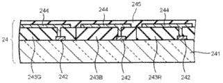
[Fig. 2] is depicted as the diagrammatic cross-section of the instance of the COA substrate that can be used among the present invention.
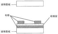
[Fig. 3] is depicted as the diagrammatic cross-section of instance of the subtend substrate of the COA substrate that can be used among the present invention.
[Fig. 4] is depicted as the sectional view of the instance that can be used for the liquid crystal display cells among the present invention.
[Fig. 5] is depicted as the sectional view of the instance that can be used for the liquid crystal display cells among the present invention.
[Fig. 6] is the top view that can be used for the example structure of the liquid crystal display cells electrode among the present invention.
[Fig. 7] (a) is depicted as integrally-built diagrammatic cross-section in the essential part that does not apply display element under the electric field, (b) is depicted as schematic whole sectional view, is the top view that can be used for the exemplary configurations of the liquid crystal display cells electrode among the present invention.
[Fig. 8] is depicted as the integrally-built block diagram of exemplary display devices essential part of the present invention.
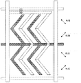
[Fig. 9] is depicted as the top view of the exemplary configurations that illustrates the liquid crystal display cells electrode that can be used among the present invention.
Embodiment
The present invention below is detailed.It should be noted that in patent specification, adopt " ...-... " or " ... extremely ... " any numerical value statement of mode can be used to expression and comprises respectively by in "-" before and the scope of the lower limit of numeric representation afterwards and the upper limit.
In this manual, Re (λ) (unit: nm) and Rth (λ) (unit: nm) be illustrated in separately and postpone in the face of sample, film etc. under the wavelength X and along the delay of thickness direction.Utilize KOBRA-21ADH or WR (available from Oji Scientific Instruments),, measure Re (λ) through on the normal direction of film, applying the light that wavelength is λ nm.
When characterizing film to be tested, then calculate its Rth (λ) according to following method with single shaft or twin shaft index ellipsoid.
The sloping shaft (turning axle) that slow axis in the face (utilizing KOBRA 21ADH or WR to measure) is regarded as film (does not have at film under the situation of slow axis; The turning axle of film can be an any interior direction at film); Apply the light that wavelength is λ nm through vergence direction from film; With 10 ° serve as at interval until with respect to normal direction+50 of film °, measure the Re (λ) of films at its 6 all points; According to the length of delay, the assumed value of refractive index and the thickness of input that record, calculate Rth (λ) then.
Will be in the face of normal direction slow axis be regarded as the turning axle of film, when film has zero delay value at certain inclination angle, then become negative sign at symbol greater than the length of delay of the film under the inclination angle at this inclination angle, be applied to KOBRA21ADH then or WR calculates.
Slow axis is regarded as sloping shaft (turning axle) (do not have at film under the situation of slow axis, the turning axle of film can be an any interior direction at film), on the both direction that tilts arbitrarily, measures the length of delay of film; According to the film thickness of data and mean refractive index and input, can calculate Rth according to following formula (21) and (22):
(21):
(22):
Wherein Re (θ) is meant the length of delay at film on the direction of normal direction tilt angle theta; Nx is meant refractive index in the face of film on slow-axis direction; Ny is meant refractive index in the face of film on perpendicular to the direction of nx; Nz is meant the refractive index of film on perpendicular to the direction of nx and ny; D is the thickness of film.
When film to be tested can not be explained with single shaft or twin shaft index ellipsoid, also promptly, when film does not have optic axis, then can calculate its Rth (λ) according to following method.
Slow axis in the face (utilizing KOBRA 21ADH or WR to measure) is regarded as the sloping shaft (turning axle) of film; Apply the light that wavelength is λ nm through vergence direction from film; With 10 ° serve as at interval with respect to the normal direction of film from-50 ° to+50 °, at the Re (λ) of its 11 all somes mensuration films.According to the film thickness of the Re that records thus (λ) delayed data, mean refractive index and input, utilize KOBRA 21ADH or WR to calculate the Rth (λ) of film.
Mean refractive index can adopt the value of the various types of bloomings described in the catalogue.When mean refractive index was unknown, available Abbe refractometer was measured.The mean refractive index of main blooming is described below: cellulose ethanoate (1.48), cyclic olefin polymer (1.52), polycarbonate (1.59), polymethylmethacrylate (1.49), polystyrene (1.59).
In mean refractive index and film thickness input KOBRA 21ADH or WR, calculate nx, ny and nz with it.From nx, ny and the nz data of calculating thus, further calculate Nz=(nx-nz)/(nx-ny).
In this instructions, Re and Rth are at wavelength 550nm, only if in it is measured other clear and definite specified wavelength.Term " slow axis in the face " is meant direction in the face that draws largest refractive index, and term " fast axle in the face " is meant the direction perpendicular to slow axis in the face.Term " visible region " is meant the scope of 380nm-780nm.
The present invention relates to adopt liquid crystal indicator through the blue phase of polymer stabilizing; Relate to the liquid crystal indicator of employing particularly through the blue phase of polymer stabilizing; Wherein arrange array base palte as the substrate that is used for liquid crystal cells to one of, and arrange that the subtend substrate that do not have color-filter layer is as right another of this substrate.Known utilization is controlled without any need for orientation through the liquid crystal indicator of the blue phase of polymer stabilizing, and shows wide visual angle characteristic.But the inventor's result of study finds, with regard to positive CR, is inferior to other liquid crystal display mode mutually through the indigo plant of polymer stabilizing.One of its reason is to be orientated defective.Indigo plant through polymer stabilizing has its medium blue mutually by the structure of polymkeric substance-network stabilization, and therefore, reason is that the orientation of liquid crystal is easy to the heterogeneity that becomes, and is easy to take place any orientation defective.Because the scattering phenomenon that the liquid crystal in the orientation defect part causes, positive (hanging down as for the direction of visible surface) CR possibly lower.When the polymkeric substance-network that produces is incomplete, possibly be easier to take place the orientation defective.Through the liquid crystal cells of the blue phase of polymer stabilizing can through fill with any blue phase liquid crystal substrate between the space, carry out photocrosslinking reaction etc. then and prepare with formation polymkeric substance-network.The inventor is through unremitting research; The result finds that so do, all or part of surface of liquid crystal cells possibly not receive ultraviolet uniform irradiation; Because the filter substrate of liquid crystal cells or array base palte can prevent ultraviolet transmission, therefore can stop the progress of photocrosslinking reaction.Therefore, reaction possibly carried out not exclusively, and it is imperfect that the structure of polymkeric substance-network possibly become, and this possibly be a reason that causes the orientation defective.In the liquid crystal cells of routine, arrange array base palte as substrate to one of, and arrange filter substrate another substrate as this substrate centering; Therefore, from any side irradiation ultraviolet radiation, photocrosslinking reaction etc. becomes incomplete.
According to the present invention, arrange array base palte as substrate to one of, arrange that the subtend substrate that does not have color-filter layer is as another right substrate of this substrate; And if from subtend substrate one side irradiation ultraviolet radiation, blue phase liquid crystal is shone in then available ultraviolet ray equably, can not reduce transmittance because of any color filter.Therefore, photocrosslinking stable reaction and fully carrying out stably produces thus and is used to make blue phase stable polymer-network.Mutually can be if blue more by polymkeric substance-network stabilization, the orientation defective can less take place, and the positive CR that then can reduce due to the light scattering that causes because of the liquid crystal in the orientation defect part reduces.Polymkeric substance-network condition that people do not study through the blue phase of polymer stabilizing at all as yet can influence positive CR, and the inventor has found this point.
One embodiment of the invention are the liquid crystal indicators with COA structure, wherein arrange the COA substrate as substrate to one of, and arrange that the subtend substrate do not have color-filter layer is as another right substrate of this substrate.If from subtend substrate one side irradiation ultraviolet radiation, then ultraviolet ray can be shone blue phase liquid crystal equably, can not reduce transmittance because of any color filter or array.Therefore, photocrosslinking stable reaction and fully carrying out stably produces thus and is used to make blue phase stable polymer-network.If polymkeric substance-network makes indigo plant stable mutually to a greater degree, then be orientated defective and can take place hardly, the positive CR that can reduce thus due to the light scattering that causes because of the liquid crystal in the orientation defect part reduces.
Though proposed the COA structure not know also that as structure that can enlarged openings rate (aperture ratio) this structure can be applicable to the liquid crystal cells through the blue phase of polymer stabilizing.Can improve transmittance through utilizing COA structure enlarged openings rate in white states; On the other hand, positive CR depends on two transmittances (shiny black degree and white luminance) under the black and white state, therefore, comes the enlarged openings rate not necessarily can directly cause the improvement of positive CR through utilizing the COA structure.
Another embodiment of the invention is the liquid crystal indicator that does not have color filter, and wherein said liquid crystal cells does not have color filter, and the mode that drives with the field preface is driven.According to field preface type of drive, through using the back light unit of launching three primary colors (RGB) continuously independently, can in addition have no under the situation of color filter and realize panchromatic demonstration.According to adopting a liquid crystal cells of preface type of drive; On the subtend substrate of said array base palte, do not arrange color-filter layer; And if from said subtend substrate-side irradiation ultraviolet radiation, blue phase liquid crystal is shone in then available ultraviolet ray equably, can not reduce transmittance because of any color filter.Therefore, photocrosslinking stable reaction and fully carrying out stably produces thus and is used to make blue phase stable polymer-network.If polymkeric substance-network can make indigo plant stable mutually to a greater degree, the orientation defective takes place hardly, can reduce reducing of positive CR due to the light scattering that causes because of the liquid crystal in the orientation defect part thus.Polymkeric substance-network condition that people do not study through the blue phase of polymer stabilizing at all as yet can influence positive CR, and the inventor has found this point.
Usually; Become isotropy through the blue of polymer stabilizing at black state, therefore, along normal direction through being positioned at rear side (promptly; Backlight side with respect to blue phase liquid crystal) though the linearly polarized light of the polarizer through still keeping polarization state after the liquid crystal layer; And on principle, its absorption axes that is arranged in the polarizer of the face side observation side of blue phase liquid crystal (that is, with respect to) absorbs fully.That is, on principle, can suppose that light leak does not take place normal direction in the black state lower edge.But the transmittance along normal direction under black state is non-vanishing.A known reason is, the liquid crystal molecule fluctuation in the liquid crystal layer, and the light of entering liquid crystal layer can be owing to scattering to a certain degree takes place in this fluctuation.In addition, the generation of light scattering is also because the liquid crystal in the orientation defect part.
The inventor finds that after deliberation the transmittance under black state not only can receive the influence of the liquid crystal molecule fluctuation in the liquid crystal layer, but also the influence that can be placed any element between the liquid crystal cells and the light source side polarizer.
Sensing light from backlight can pass through the light source side polarizer, and because light delay of the element of process before getting into liquid crystal cells, the light of vergence direction can be converted to elliptically polarized light.Thereafter, elliptically polarized light can get into liquid crystal cells.Thereafter, elliptically polarized light can get into liquid crystal cells.The inventor finds after deliberation; Because the optical phenomena that when elliptically polarized light runs into each element (the for example projection of the structure of liquid crystal, color filter, black matrix (matrix), array base palte, subtend substrate, the slit of conventional electrodes on the subtend substrate), produces by each element in the liquid crystal cells; For example diffraction and scattering; Elliptically polarized light can be in the normal direction scattering, and the result can reduce positive CR.If linearly polarized light through behind the polarizer and before getting into liquid crystal cells the delay of each element of process low, can prevent that then transmittance black state under is because of the increase of the optical phenomena of each element generation in the liquid crystal cells.Therefore, according to the present invention, more preferably place the delay of the hyaline membrane between the light source side polarizer and the liquid crystal layer less.More specifically; According to wherein placing hyaline membrane between the light source side polarizer and the liquid crystal layer | Re (550) | be equal to or less than 20nm, and this hyaline membrane | Rth (550) | be equal to or less than the embodiment of 90nm; Can prevent light leak along inclined direction takes place under black state, and further improve positive CR.
In addition, the delayed impact that is arranged in the hyaline membrane between the light source side polarizer and the liquid crystal layer under black state vergence direction take place painted, that is, black colorant changes (color offset).The inventor finds after deliberation; If place hyaline membrane between the light source side polarizer and the liquid crystal layer | Re (550) | be not more than 10nm and this hyaline membrane | Rth (550) | be not more than 30nm; Then not only positive CR can be further improved, and the painted of vergence direction can be reduced through above-mentioned functions.More specifically; Be adjusted to above-mentioned scope through the optical property that will place the hyaline membrane between the light source side polarizer and the liquid crystal layer; Not only can realize high positive CR value; Promptly at white and the transmittance of black state than (brightness ratio), and can reduce under black state along inclined direction at the light leak of wide wavelength coverage, reduce painted variable quantity thus at vergence direction.
According to the present invention; Place length of delay (Re) in the face of the hyaline membrane between the backlight side polarizer and the liquid crystal cells through optimization, along the delay (Rth) of thickness direction; And preferred wavelength dispersion characteristic Re and Rth, can be implemented under the black state low light leak and along the high CR of normal direction.
Liquid crystal indicator of the present invention is compatible with the coplanar switched system, and is suitable for increasing the size of LCDs and improves its quality.
Utilization of the present invention also has the following advantages through the liquid crystal indicator of the blue phase liquid crystal of polymer stabilizing.
At first; No longer need be used to control the surface orientation processing of liquid crystal material orientation; Thereby can omit all orientation/wash/dry regimen, indispensable passing through is coated on the step that forms alignment films/drying/heat curing/friction on the substrate surface for the display element of routine specifically.Because these processes can pollute because of the static and the friction of exotic such as dust and particle, they all can cause the decline of yield ratio and display performance, so the omission of these processes can help avoid the decline of yield ratio and display performance.
Secondly, the conventional liquid crystal display cells based on the variation of the state of orientation of nematic crystal on principle has been subject to response speed in essence, and with regard to the film display performance, is inferior to competitive Plasmia indicating panel, EL display panel etc.The blue phase liquid crystal through polymer stabilizing that utilization can respond in about 100 μ s has solved problem now.
The instance of the spendable blue phase liquid crystal material through polymer stabilizing of the present invention comprises the compound liquid-crystal composition; It comprises the combinations of low molecular weight liquid crystals that can between cholesterol phase and isotropic phase, present blue phase, and the polymer network that in said combinations of low molecular weight liquid crystals, forms.Said polymer network is through noncrystalline or crystalline monomer and crosslinking chemical polymerization formation.Said blue phase liquid crystal material through polymer stabilizing preferably comprises chiral dopant.Chiral dopant can influence the wavelength through the diffraction that blue phase liquid crystal appeared of polymer stabilizing with respect to the amount through the blue phase liquid crystal of polymer stabilizing.The addition of the said chiral dopant of scalable also is so that the wavelength of the diffraction that appears through the blue phase liquid crystal of polymer stabilizing is outside visible region (380-750nm).The liquid crystal indicator through the blue phase liquid crystal material of polymer stabilizing that utilization comprises the chiral dopant of said amount can further be reduced in the light leak under the black state.
The monomer that can be used for forming said polymkeric substance-network can be selected from non-liquid crystal type monomer or liquid crystal monomer; And non-liquid crystal type monomer is more effective than liquid crystal monomer.
Non-liquid crystal type monomer is optional from carrying out polymerization and not have the bar-shaped molecular structure monomer of (for example, containing the xenyl of end alkyl, cyanic acid, fluorine atom etc. or the molecular structure of xenyl cyclohexyl) according to photopolymerization or thermal polymerization; The instance of this type of monomer includes but not limited to contain the monomer such as the polymerisable group of acryloyl group, methacryl, vinyl, epoxy radicals, fumarate or cinnamoyl base class.
The instance that can be used for the monomer except said non-liquid crystal type monomer among the present invention comprise bar-shaped or disk-like structure with phenyl or cyclohexyl and state separately or with the admixture of other molecule under present the monomer of liquid crystal liquid crystal property.
Also can use the monomer that contains 2 or a plurality of polymerisable groups in each molecule.
The preferred embodiment of said non-liquid crystal type monomer comprises: the monomer based on acrylic ester that contains acryloyl group or methacryl; Preferred instance comprises with the monomer based on acrylic ester of alkyl as the side chain of side chain.For example, can preferably use per molecule to contain at least one C
1-4The monomer of alkyl side chain.The instantiation of said monomer based on acryloyl group comprises cyclohexyl acrylate; The said instantiation based on the monomer of acryloyl group that contains alkyl side chain comprises acrylic acid (2-ethylhexyl) ester and acrylic acid (1,3,3-trimethyl hexyl) ester.
Said polymer network said monomer capable of using and crosslinking chemical form when polymerization.Said crosslinking chemical can be selected from that have can be through being connected to form the non-liquid crystal or the liquid-crystal compounds of the reactive group of network structure with the monomer molecule that will use.For example, according to an embodiment preferred of wherein using based on the monomer of acrylic ester, said crosslinking chemical can be selected from the diacrylate monomer that shows liquid crystal liquid crystal property.
On the other hand, optional as the combinations of low molecular weight liquid crystals of one of said blue phase liquid crystal component through polymer stabilizing from forming blue combinations of low molecular weight liquid crystals mutually between cholesterol phase (Chinrally nematic phase) and the isotropic phase.Preferably, it is selected from the thermotropic liquid crystal that its molecule has the bar-shaped geometric configuration of length prolongation, and the optional liquid crystal material of having developed that is used for liquid crystal display cells.The instance of this type of combinations of low molecular weight liquid crystals comprises the compound that contains xenyl, terphenyl or xenyl terphenyl part, and its state separately down since exist chiral atom, perhaps with the admixture of chiral material (chiral dopant) under present cholesterol that pitch is equal to or less than 500nm (Chinrally nematic phase) mutually.Usually, multiple said combinations of low molecular weight liquid crystals use capable of being combined.
Chiral dopant is selected from the compound that can produce the liquid crystal spiral status; Chat after the instance of said chiral dopant is included in " ZLI-4572 " that use among the embodiment, the CB15 shown in following and following shown in have an also compound (a)-(h) of [3,2-b] furans of furans.
Chiral dopant ZLI-4572
Chiral dopant CB15

1,4:3,6-two dehydration-L-glucitols-(9CI) 1,4:3,6-two dehydration-DL-glucitols-(8CI)

1,4:3,6-two dehydration-D-iditols-(9CI) 1,4:3,6-two dehydration-mannitols-(6CI, 7CI, 8CI, 9CI)

1,4:3,6-two dehydration-L-iditols-(9CI) 1,4:3,6-two dehydration-iditols-(6CI, 7CI, 8CI, 9CI)
1,4:3,6-two dehydration-D glucitols-(9CI) 1,4:3,6-two dehydration-D-mannitols-(9CI)
Generally speaking, chiral dopant can be used as the stable adjuvant of helical structure that can make the TN-pattern, perhaps induces the adjuvant of spiral phase, for example cholesterol phase or chirality smectic phase.
According to the present invention, said pitch is preferably than common weak point; And the chiral dopant with king bolt distortion power (HTP) that adds high concentration is for preferred.Therefore, said chiral dopant is preferably selected from and shows big HTP and the compound high as far as the liquid crystal dissolubility.
Lan Xiangke forms as follows.Monomer and crosslinking chemical are dispersed in the combinations of low molecular weight liquid crystals; Under the temperature that can keep blue phase, carry out the polymerization of dispersion then.
Said polymerization can be carried out according to thermal polymerization or photopolymerization; Because possibly there is restriction in thermal polymerization on the polymerization temperature and aspect blue overlapping between mutually; And the state of said polymer network possibly change along with heating, the therefore preferred photopolymerization of adopting ultraviolet light.In order to promote polymerization, preferably at least a polymerization initiator is scattered in the said combinations of low molecular weight liquid crystals with monomer, chiral dopant and crosslinking chemical.The instance of photo-induced polymerization initiator comprise based on acetophenone, based on benzophenone, based on benzoin ether and based on the compound of thioxanthones; Instantiation comprises 2,2-dimethoxy-2-phenyl acetophenone.
Typically can be through the amount of following steps adjustment chiral dopant with respect to said blue phase liquid crystal through polymer stabilizing so that by said wavelength through the diffraction that the blue phase liquid crystal of polymer stabilizing appears outside visible region (380-750nm).
(1) preparation is added with the blue phase liquid crystal through polymer stabilizing of an amount of chiral dopant.
(2) utilize grating spectrograph (for example), measure the wavelength of the diffraction of liquid crystal surfactant through universal method available from the micro-UV/ visible light photometer 350 of JASCO Corporation.
(3) confirm to make the amount of the chiral dopant of diffraction wavelength outside visible region.
Depend on the HTP (helically twisted power) of chiral dopant according to the amount of the chiral dopant of said determination, and change along with the kind of chiral dopant and liquid crystal.For liquid crystal is that JC1041-XX and chiral dopant are the sample situations of ZLI-4572, and the amount of ZLI-4572 is about 6-10mol%, and the consumption that CB15 substitutes when being used as chiral dopant is about 85-95mol%.
Fig. 1 schematically for example understands the structure of liquid crystal indicator of the present invention.Through placing the blue phase liquid crystal display element LC between 2 polaroid PL1 and the PL2, the liquid crystal indicator shown in the design of graphics 1 through polymer stabilizing.By placing 2 hyaline membranes 14, polarizer film 10 configuration polaroid PL1 between 18, by placing 2 hyaline membranes 16, polarizer film 12 configuration polaroid PL2 between 20.In two groups of assemblies of these hyaline membranes; Place more contiguous hyaline membrane 14 and 16 on the blue phase liquid crystal display element LC of polymer stabilizing one side may influence display performance; And place, and can not influence display performance away from said hyaline membrane 18 and 20 diaphragms on blue phase liquid crystal display element one side of polymer stabilizing as polarizer film 10 and 12.Liquid crystal indicator shown in Fig. 1 have as the substrate of liquid crystal cells to one of COA substrate 24, and the subtend substrate that does not have a color-filter layer is as another right substrate of this substrate.Through from subtend substrate 22 irradiating ultraviolet light to form polymer network, can carry out cross-linking reaction fully, improve the degree of crosslinking in this polymer network thus.As a result, compare through the blue liquid crystal indicator mutually of polymer stabilizing with the utilization of routine, the light leak that under black state, takes place at frontal reduces, and positive CR has improvement.
According to embodiment, wherein place the hyaline membrane 16 of light source side (if in Fig. 1 light source arrangement at downside) | Re (550) | be equal to or less than 20nm, and its | Rth (550) | be equal to or less than 90nm, just can further improve positive CR.Through further reducing the delay of hyaline membrane 16; Perhaps preferably through control its wavelength dispersion characteristic Re and Rth; Not only can further reduce under black state the light leak of frontal with improve positive CR, also can reduce under black state vergence direction take place painted.More specifically, preferably, the Re absolute value of hyaline membrane 16 | Re (550) | be not more than 10nm, and the Rth absolute value of hyaline membrane 16 | Rth (550) | be not more than 30nm.More preferably, the Re absolute value of hyaline membrane 16 | Re (550) | be not more than 5nm, and the Rth absolute value of hyaline membrane 16 | Rth (550) | be not more than 10nm.In addition, the Re of hyaline membrane 16 and Rth preferably show less wavelength dependency, and the absolute value of Re and Rth preferably satisfies above-mentioned condition at whole visible region.More specifically, for the wavelength dispersion characteristic Re and the Rth of hyaline membrane 16, | Re (400)-Re (700) | preferably be equal to or less than 10nm, and | Rth (400)-Rth (700) | preferably be equal to or less than 35nm; | Re (400)-Re (700) | more preferably be equal to or less than 5nm, and | Rth (400)-Rth (700) | more preferably be equal to or less than 10nm.
The Re of hyaline membrane 16 (400) is preferably-5nm to 5nm; And the Rth of hyaline membrane 16 (400) is preferably-10nm to 10nm.
The Re of hyaline membrane 16 (700) is preferably-5nm to 5nm; And the Rth of hyaline membrane 16 (700) is preferably-10nm to 10nm.
Through controlling the optical property of the hyaline membrane 14 that will be arranged in the display board side, can improve the demonstration character of said device more.
In an example, hyaline membrane 14 also can satisfy the hyaline membrane 16 required optical properties that appear.
In another example, hyaline membrane 14 can be the optics biaxial film.In this example, preferably, the Re of hyaline membrane 14 is pact-88nm about 88nm extremely for the about 350nm of about 200nm-and Rth, more preferably, the Re of hyaline membrane 14 for about 300nm of about 250nm-and Rth be-45nm extremely-45nm.
In another example, hyaline membrane 14 is made up of 2 optics biaxial film.In this example, preferably the Re of one of these 2 films is the about 120nm of about 20-, and Rth is the about 225nm of about 125-, or more preferably, Re is the about 100nm of about 40-, and Rth is the about 205nm of about 145-; Preferably, the Re of another sheet film in these 2 films is approximately-30 to about 30nm, and Rth be the about 150nm of about 50-, or more preferably, Re is a pact-10 to about 10nm, and Rth is the about 120nm of about 80-.
In another example, hyaline membrane 14 is made up of 2 optics uniaxial film.In this example, preferably the Re of one of these 2 films is the about 210nm of about 60-, and Rth is the about 105nm of about 30-, or more preferably, Re is the about 160nm of about 110-, and Rth is the about 80nm of about 55-; And preferably, the Re of another sheet film in these 2 films is approximately-30 to about 30nm, and Rth be the about 80nm of about 55-, or more preferably, Re is a pact-10 to about 10nm, and Rth is the about 140nm of about 100-.
Hyaline membrane 18 and 20 is respectively the outer diaphragm of polaroid PL1 and PL2, and can have functional layer in the above.For example, hyaline membrane 20 can have functional membrane on its backlight side surface, for example antifouling film, antireflection film, antiglare film and antistatic film.Identical with hyaline membrane 20, hyaline membrane 18 can have functional membrane in its surface, for example antifouling film, antireflection film, antiglare film and antistatic film.
Liquid crystal indicator shown in Fig. 1 is furnished with and places the back light unit (not shown) of rear side polaroid (according to the polaroid PL2 of the embodiment shown in Fig. 1) than far ultraviolet portion.According to the present invention, the light source in the back light unit is preferably led light source, or more preferably for being located immediately at the led light source of bottom type.Through using led light source, can be reduced in the transmittance of black state, and improve positive CR.
Liquid crystal cells LC has a pair of substrate 22 and 24 and be packaged in the liquid crystal cells through the blue phase liquid crystal material of polymer stabilizing between the substrate, wherein applies electric field abreast with base plan.Preferably, apply electric field through two comb poles of installing to the surface of a substrate with interlaced mode.In practice, feasible method can be, for example utilize any the source electrode in these two electrodes, and utilize another as ordinary electrode as thin film transistor (TFT) (TFT), thus can be according to TFT operation start-close electric field.More specifically, can be preferably ordinary electrode and TFT electrode be assembled to the surface of a substrate, and by means of the startup of TFT-close conversion, and input signal applies electric field accordingly between TFT electrode and ordinary electrode.
The substrate of liquid crystal cells LC to 22 and 24 in, the substrate 24 that places light source side is the color filters on array base palte; And have the color-filter layer on tft array, not shown in this point diagram.In the COA substrate, the thickness of color-filter layer is greater than (about 2 microns of about 1-) of conventional type color filter, and is generally about 4 microns of about 2-.This is used to prevent between pixel electrode edge and circuit, produce parasitic capacity.The thickness of the color-filter layer in the liquid crystal indicator of the present invention is preferred but be not limited to about 4 microns of about 2-.When utilizing COA substrate manufacture liquid crystal cells, need carry out patterned to the pixel electrode on the color filter; And need have corrosion stability to etching solution or stripper.In order to reach this purpose, but used thickness is adjusted to certain more color filter materials of levels thickness (coloured photosensitization property composition); The double-layer structure of the color-filter layer that perhaps also can use outer covering layer and form by common color filter materials.According to the present invention, can use all COA substrates with any structure.
Shown in Figure 2 for illustrating the schematic cross sectional view of the instance of COA substrate 24 among Fig. 1.
Though the details of COA structure is described in this manual, the detailed structure of COA substrate can be in for example above-mentioned patent document 6 and 7 and the spy opens 2007-240544, the spy opens among 2004-163979 and the Te Kai 2008-15375 and finds.
In COA type liquid crystal indicator, with regard to the degree of crosslinking that increases said polymer network, preferably will deceive matrix and place the COA substrate; But, because the influence of black matrix maybe be little, so black matrix can place any position of liquid crystal cells; For example, at glass substrate place as the subtend substrate.
Shown in Figure 3 is the diagrammatic cross-section of the instance of the subtend substrate 22 in the key diagram 1.
According to the present invention, in having the embodiment of color filter, color filter need be arranged on the array base palte.The color filter that can be used among the present invention is identical with common color filter in the liquid crystal indicator, and wherein multicolour (for example red, green and blue three primary colors, and Transparent color, yellow and cyan) is arranged in each pixel.The various methods that prepare color filter are arranged; Its a kind of method instance is following: will be also referred to as coloured (once in a while maybe the be colourless) photo-sensitive composition of " color resist (color resist) ", through coloured material (for example organic pigment/dyestuff and carbon black) is coated the substrate surface cambium layer, and prepare according to photo-engraving process formation figure then.Recently, also be called the figure of " extend boundary line (elongation barrier) " in formation after, form the color zones of pixel according to ink ejecting method.Except that them, also known have other method, comprises method, print process, electrodeposition process and the film transfer printing of the combination that utilizes coloured non-photosensitivity property composition and positive type photosensitive anticorrosive additive material.Color filter used among the present invention can be selected from those that make according to any method.
Be used to prepare the not restriction of material of said color filter.Any material such as dyestuff, organic pigment and inorganic pigment can be used as coloured material.Carried out dyestuff research to increasing CR, still, the dispersion technology of organic pigment is existing recently improves, and can grind method according to salt the pigment of pulverizing is pulverized in microscopic particles, perhaps will prepare microcosmic pigment according to the existing method that is used to increase CR.According to the present invention, can use any coloured material.
It should be noted, as stated, according to the embodiment of utilizing said preface drive system, without any need for color filter.
The array base palte or the insulated substrate that are used as the liquid crystal cells of its subtend substrate can be preferably transparency carrier, wherein can adopt glass, plastic foil, optical crystal etc.
The right spacing of substrate is adjusted to the about 100 μ m of 2-usually.
The electric field that applies is generally the about 100000V/cm of 1000-.Maybe be enough good be the electric field that applies parallel with substrate basically (the perhaps normal direction of display).
Apply the not special restriction of system of electric field, therefore wherein a kind of simple structure can be two comb poles of for example on the surface of a substrate, assembling with interlaced mode.Each comb poles preferably has about 2-100 rooted tooth, and length is about 1-10000 μ m, and width is about 1-50 μ m, and the distance between tooth and the tooth is about 1-100 μ m.
According to the present invention, can two comb poles be assembled on the same level of substrate with interlaced mode, and can apply voltage betwixt, thereby be created in the normal direction and the electric field parallel of tooth with real estate.Another substrate is the glass plate of the electrode that do not have on it to form, and with its arrangement interval thing relatively, for example intervenient film.Thus this substrate between produce the gap be equivalent to sept thickness, in the gap, inject liquid crystal material, with preparation liquid crystal display cells LC.
When between two relative comb poles, applying voltage, produce the mono-axial refractive index anisotropy, simultaneously the direction that is oriented to electric field of its optic axis or until in the direction of tooth.
Through liquid crystal display cells LC being placed between two polaroid PL1 and the PL2; Make absorption axes 10a and the 12a of each polaroid PL1 and PL2 be oriented to orthogonal (so-called cross Nicols arrangement); And the direction through the adjustment electric field tilts 45 ° from separately absorption axes; Make liquid crystal display cells LC not have transmissivity not having to demonstrate under the situation of electric field (is zero because postpone), and make the light can transmission (as the wavelength sheet, working) under the electric field that applies because wherein produce the unit of delay.Therefore, the on-off of voltage switch can be created in bright and black between the contrast of change.When making a half that postpones to equal the transmitted light wavelength, transmissivity (transmissivity) reaches maximal value.
As stated, with regard to the maximizing efficiency that makes delay, most preferably, the vertical absorption axes 10a and 12a from polaroid PL1 and PL2 of " comb " of the comb poles of said liquid crystal display cells LC tilts 45 °.Because under the voltage that applies, can form subregion, and can obtain more indicating characteristic uniformly at azimuth direction, thus can preferably provide+45 ° with two districts (domain) of-45 °.For example, the electrode shown in the arrangement plan 5 is to have two districts in right-hand part and left side.Perhaps, also can through as after chat the zigzag comb poles shown in Fig. 8 and obtain two districts.
It can be used for the not special restriction of electrode structure among the present invention, as long as can switch on same level.For example, the electrode structure shown in the sectional view among Fig. 4 has ordinary electrode and pixel electrode, and they all are configured to comb poles, and the electrode structure shown in the sectional view of Fig. 5 has the insulation course that places between sheet type ordinary electrode and the comb shape pixel electrode.
Fig. 7 (a) is the integrally-built diagrammatic cross-section of explanation essential part of the display element of this embodiment under the voltage that does not apply (off status of OFF), and Fig. 7 (b) is that explanation is having the integrally-built diagrammatic cross-section that applies the essential part of the display element of (ON state) this embodiment under the voltage.Fig. 7 is the exemplary integrally-built block diagram of essential part of the display device of utilizing display element of this embodiment of explanation.Use the display element of this structure, for display device driving circuit is provided simultaneously.
Display device shown in Fig. 8 has wherein arranges pixel with the display element that forms matrix, as Source drive (source driver) and gate driver, the electric power loop etc. of driving circuit.
Said display element also is furnished with many single data signal wire, and many scan signal lines that intersect with independent data signal line respectively, and wherein each combination of each data signal line and each scan signal line is furnished with pixel.
Electric power loop is that Source drive and gate driver supply show required voltage on display element, and Source drive drives the data signal line of display element thus, and gate driver drives the scan signal line of display element.
Each pixel is furnished with unshowned switching device.FET (field effect transistor) or TFT (thin film transistor (TFT)) can typically be used as said switching device, and wherein the gate electrode of switching device links to each other with each scan signal line, and the source electrode links to each other with each data signal line, and drain electrode links to each other with unshowned each pixel electrode.In this structure, when in single pixel, selecting scan signal line, switching device starts, and depends on thus from the signal voltage of the display data signal of unshowned controller input to put on display element by Source drive through data signal line.After the selection phase of scan signal line finished, in the duration that switching device keeps breaking off, display element remained on the voltage of being realized when breaking off ideally.
In this embodiment; The configuration display element; To have or not have under the electric field (voltage) through utilizing the medium [liquid crystal media (liquid crystal material), dielectric] that can present optical isotropy (if at visible region, more specifically in the wavelength of visible light scope or observe isotropy in the larger context, from enough optics same sexes at macroscopic view or specific visual angle) to show.
Fig. 7 (a) and (b) shown in display element have a pair of substrate respect to one another, with device (being used to support the device of optical modulation layer) as Supporting Media; Applying the dielectric layer that the medium that carries out optical modulation under the voltage (below be called medium " A ") is formed, and be supported on substrate between; And be arranged in the right outside of substrate, promptly two substrates with the surfaces opposite to each other opposed surface on polaroid.
This can be made up of transparency carrier such as glass substrate etc. at least one has light transmission in the substrate.This to a substrate in the substrate on; And on itself and another substrate facing surfaces; Can arrange that as applying the comb poles of the device (applying the element of electric field) of electric field this comb poles can apply almost the electric field (transverse electric field) parallel with substrate 1 to dielectric layer, shown in Fig. 7 (b); So toothed portion (comb poles) is engaged with each other as illustrated in fig. 6.Perhaps, as shown in Figure 9, relatively arrange the serrate comb poles.
Comb poles typically is made up of like the transparent electrode material that comprises ITO (indium tin oxide) electrode material, and to be adjusted to line width be 5 μ m, and electrode separation (spread of electrodes) is 5 μ m, and thickness is 0.3 μ m.Notice that the above-mentioned value of said electrode material and line width, electrode separation and thickness only is exemplary, does not limit the present invention.
According to the present invention; In the typical method of making display element; Can utilize not illustrational encapsulant with the substrate that has comb poles on it and another base plate bonding; Randomly add simultaneously not illustrational sept, for example plastic bead, spun glass etc., and form liquid crystal layer betwixt.
The adoptable liquid crystal of this embodiment is the variable medium of optically anisotropic degree under the voltage that applies.Applied electric field E by the outside
jMaterial produce electric displacement D
Ij=ε
IjE
j, be accompanied by specific inductive capacity (ε
Ij) slight modification.Because refractive index (n) square be equivalent to the specific inductive capacity under light frequency, so medium " A " also can be identified as the material that under the voltage that applies, causes refraction index changing.
Conventional liquid crystal display cells is for example, only to utilize the direction of orientation of liquid crystal molecule to change those that show with the rotation of inducing through the voltage that applies as stated.Therefore, response speed receives the influence of the intrinsic viscosity of liquid crystal widely, because liquid crystal molecule will rotate together, will keep their homogeneous state of orientation constant simultaneously.By contrast, the liquid crystal indicator of this embodiment utilizes the optically anisotropic degree change of medium to show.Therefore, be different from conventional liquid crystal display cells, response speed is influenced by the intrinsic viscosity of liquid crystal no longer greatly, can realize quick response thus.The liquid crystal indicator of this embodiment is because its essence that responds fast preferably also can be applicable to typical display device based on the field sequential color system.Open the spy that can quote that 2005-181667, spy open 2009-42446, the spy opens a preface drive system has been detailed in 2007-322988 and the Japanese Patent Laid 3996178.Drive according to the field preface, use the back light unit of launching primaries continuously and independently.Preferably being the back light unit of light source with LED, is the back light unit of light source with emission three primary colors redness, green and blue LED matrix more preferably.
Next explanation can be used for first and second hyaline membranes (Reference numeral 14 and 16 among Fig. 1) among the present invention.
With regard to making said liquid crystal indicator attenuation, first and second hyaline membranes of the present invention are preferably used as the diaphragm of said polaroid.Therefore, according to the present invention, the polymer film that is formed by the various materials that can be used as diaphragm can be used as said hyaline membrane.
[based on the film of cellulose acylate]
With regard to being applicable to the said polaroid of processing, the film that is preferably based on cellulose acylate is as first or second hyaline membrane.Reduce agent through adding the following delay that will describe, can prepare and satisfy the optical property that the said first hyaline membrane needs have, the film of promptly low Re and low Rth based on cellulose acylate.In addition; Following through adding with the wavelength dispersion controlling agent of describing; Can prepare the wavelength dispersion characteristic Re and the Rth that present expectation, promptly | Re (400)-Re (700) | be not more than 10nm and | Rth (400)-Rth (700) | be not more than the film of 35nm based on cellulose acylate.
On the other hand, through adding the following delay elevator that will describe and/or implementing stretch processing, can prepare the polymkeric substance that demonstrates optics twin shaft or single shaft, and this type of cellulose acylate film can be used as said second hyaline membrane based on cellulose acylate.
The cellulosic material that is used for cellulose acylate comprises velveteen and wood pulp (hard wood pulp and soft wood pulp), and can use the cellulose acylate that is obtained by any this type of cellulosic material.Depend on the circumstances, can use the potpourri of those cellulosic materials at this.These raw celluloses are at for example " Plastic Materials Lecture (17); Cellulose Resins " (Marusawa and Uda work; Nikkan Kogyo Shimbun; (1970)) and among Hatsumei Kyokai ' the s Disclosure Bulletin 2001-1745 (pp.7-8) detailed description is arranged, wherein described those celluloses can be used for the present invention.But, any special restriction that do not have of said cellulose acylate film.
Below describe and prepare cellulose acylate from above-mentioned cellulosic material.Prepare cellulose acylate through the hydroxyl in the cellulose is carried out acidylate, wherein the substituting group acyl group can contain 2 carbon atoms (acetyl group)-22 carbon atom.In cellulose acylate, the not special restriction of the degree of substitution of hydroxyl in the cellulose.Particularly, degree of substitution can calculate through the bonding degree of measuring acetate and/or containing the hydroxyl in the fatty acid substituted cellulose of 3-22 carbon atom.Can measure according to the method for ASTM D-817-91.
As stated, obtain not special qualification of degree of substitution of the hydroxyl in the cellulose of cellulose acylate.But preferably, the acyl substituted degree of the hydroxyl in the cellulose is 2.50-3.00, more preferably 2.75-3.00, even more preferably 2.85-3.00.
Will introduce with the acetate of the hydrogen atom of the hydroxyl in the instead of cellulose and/or contain in the fatty acid of 3-22 carbon atom, the acyl group that contains 2-22 carbon atom can be selected from aliphatic group or aromatic group, and not special restriction.One or more different types of these type of acid can be used for replacing alone or in combination.Said cellulose acylate comprises, for example, and cellulosic alkyl-carbonyl ester, alkenyl carbonyl ester, aromatic group carbonyl ester or aromatic group alkyl-carbonyl ester, and they can further be substituted.The preferred embodiment of acyl group is acetyl group, propiono, bytyry, heptanoyl group, caproyl, caprylyl, capryl, dodecane acyl group, tridecane acyl group., tetradecane acyl group, hexadecane acyl group, octadecanoyl, isobutyryl, uncle's bytyry, cyclohexane carbonyl, oleoyl, benzoyl, naphthoyl and cinnamoyl.In these, more preferably acetyl group, propiono, bytyry, dodecane acyl group, octadecanoyl, uncle's bytyry, oleoyl, benzoyl, naphthoyl (naphthylcarbonyl) and cinnamoyl; Even more preferably acetyl group, propiono or bytyry.
The acyl substituent of the hydroxyl in will substituted cellulose is when being selected from acetyl group, propiono and the bytyry at least 2 kinds and its total degree of substitution and being 2.50-3.00 basically, then can reduce the optical anisotropy of said film based on cellulose acylate.Therefore, will be in order to prepare as the cellulose acylate film of said first hyaline membrane, preferably use the cellulose acylate of acyl substituted degree as 2.60-3.00 (even more preferably 2.65-3.00).Will can confirm kind and acyl substituted degree according to the optical property of expectation as the cellulose acylate film of second hyaline membrane in order to prepare.For example, will can use any cellulose acylate of the aromatic group that contains such as phenyl as the cellulose acylate film of said second hyaline membrane in order to prepare.
With regard to its viscometric degree of polymerization, the degree of polymerization of the cellulose acylate that preferably uses among the present invention is 180-700.Particularly, the viscometric degree of polymerization of cellulose ethanoate is 180-550, more preferably 180-400, even more preferably 180-350.If the degree of polymerization is too high, the viscosity of the dope of said cellulose acylate can increase, thereby possibly be difficult to prepare said film through The tape casting.But,, possibly reduce by its film strength that makes if when the degree of polymerization of said polymkeric substance is too low.Can be through people's such as Uda limiting viscosity method (Kazuo Uda, Hideo Saito; The Journal of the Textile Society of Japan, Vol.18, No.1, pp.105-120,1962) the mensuration average degree of polymerization.This opens among the flat 9-95538 the spy has detailed description.
The molecular weight distribution of the preferred cellulose acylate that uses can be measured through gel permeation chromatography among the present invention; And what hope is that (Mw is a weight-average molecular weight for the polydispersity index Mw/Mn of said polymkeric substance; Mn is a number-average molecular weight) less, its molecular weight distribution is narrower.Particularly, the Mw/Mn value of said polymkeric substance is preferably 1.0-3.0, more preferably 1.0-2.0, most preferably 1.0-1.6.
When wherein removing lower-molecular-weight component, then the mean molecular weight of said cellulose acylate (degree of polymerization) can increase, and its viscosity possibly be lower than the viscosity of conventional cellulose acylate, and therefore, this type of cellulose acylate is favourable.Can be through removing lower-molecular-weight component, to obtain the cellulose acylate that small molecule component content reduces from the cellulose acylate that makes with conventional method.In order to remove lower-molecular-weight component, can adopt suitable organic solvent washing cellulose acylate from it.When making the cellulose acylate of small molecule component content reduction, suitably, with respect to the cellulose of 100 mass parts, the amount of sulfuric acid catalyst is controlled to be the 0.5-25 mass parts during with acetylation.The amount that preferably makes sulfuric acid catalyst is because the cellulose acylate that makes can have the preferably molecular weight distribution of (homogeneous) in this scope.When being made into film, the water cut of said cellulose acylate is preferably 2 quality % at the most, more preferably 1 quality % at the most, even more preferably 0.7 quality % at the most.The plain acylate of known fiber is moisture usually, and its water cut is 2.5-5 quality %.Have above-mentioned preferred water cut in order to be used in cellulose acylate of the present invention, must carry out drying.The not special restriction of its method of drying is as long as the dry polymkeric substance of warp can have the water cut of expectation.The method that is used for cellulose acylate of the present invention, is used for its cellulosic material and prepares it has detailed description in Hatsumei Kyokai ' s Disclosure Bulletin No.2001-1745 (March 15,2001 distribution) in the 7-12 page or leaf.
Can use one or more different types of cellulose acylates alone or in combination at this.
Can be with in the said film of at least a adding that is selected from the following various adjuvants (for example reducing optically anisotropic compound, wavelength dispersion-controlling agent, UV suppressant, plastifier, antioxidant, fine grained, optical property-controlling agent) based on cellulose acylate.Will be in order to prepare as the film based on cellulose acylate of first hyaline membrane with low Re and low Rth, preferably use and at least aly can reduce optically anisotropic compound.This type of examples for compounds comprises those that meet the following conditions.
(Rth
(A)-Rth
(0))/A≤-1.0
0.01≤A≤30
In this condition, " Rth
(A)" represent that amount is the Rth (nm) of the film that can reduce optically anisotropic compound of " A " %; " Rth
(0)" expression do not contain the Rth (nm) of film of said compound; And the said compound of " A " expression accounts for the mass percent (quality %) of contained main polymer quality in the said film.
Saidly can reduce optically anisotropic compound and preferably meet the following conditions.
(Rth
(A)-Rth
(0))/A≤-2.0
0.1≤A≤20
The optically anisotropic compound of said reduction can be selected from can be with said polymkeric substance fully miscible and itself do not have the compound of club shaped structure and flat structure.Particularly, when said compound contains a plurality of flat functional groups such as aromatic group, then advantageously so design the structure of said compound, it is had not on same plane but in nonplanar functional group.
Will be in order to prepare as the film based on cellulose acylate of said first hyaline membrane; As stated; Can add compound to this film, this compound can suppress polymkeric substance in this film orientation on direction and the thickness direction in face, reduces the optical anisotropy of this film thus.Preferably, the octanol-water partition coefficient of said compound (log P value) is 0-7.Log P value is poor greater than the compatibility of 7 compound and polymkeric substance, and it can make the film albefaction that makes or can make said film burnt hair.On the other hand, log P value is highly hydrophilic less than 0 compound, and it can make the water proofing property variation of the film that makes.More preferably, the log P value of said compound is 1-6, even more preferably 1.5-5.
Octanol-water partition coefficient (log P value) can be according to JIS, and the flask infusion method described in the Nippon Industrial StandardsZ7260-107 (2000) is confirmed.Replace actual measurement, octanol-water partition coefficient (log P value) can be according to chemistry method or empirical method estimation.As for computing method, preferred Crippen fragment method (J.Chem.Inf.Comput.Sci., 27; 21 (1987)), Viswanadhan fragment method (J.Chem.Inf.Comput.Sci., 29,163 (1989)), Broto fragment method (Eur.J.Med.Chem.-Chim.Theor.; 19,71 (1984)); More preferably Crippen fragment method (J.Chem.Inf.Comput.Sci., 27,21 (1987)).When having different log P values, preferably can judge whether within the scope of the invention this compound according to the Crippen fragment method according to used assay method or computing method compound.
Saidly can reduce optically anisotropic compound and can contain or not contain aromatic compounds.Preferably, the said molecular weight that can reduce optically anisotropic compound is 150-3000, more preferably 170-2000, even more preferably 200-1000.The said compound of molecular weight in said scope can have the certain monomers structure, perhaps can have the oligomer structure or the polymer architecture of this type of monomeric unit that comprises a plurality of bondings.Saidly can reduce that optically anisotropic compound preferably is in a liquid state or fusing point is 25-250 ℃ a solid under 25 ℃, more preferably be to be in a liquid state or fusing point is 25-200 ℃ a solid at 25 ℃.Preferably in addition saidly can reduce optically anisotropic compound and in the dope curtain coating of system film and dry run, do not evaporate.
The amount of the optically anisotropic compound of reduction that adds to said film preferably accounts for the 0.01 quality %-30 quality % of this film solid content (being said polymkeric substance basically), more preferably 1 quality %-25 quality %, even more preferably 5 quality %-20 quality %.
Can use the optically anisotropic compound of a kind of said reduction individually, perhaps can use any potpourri that makes through with two kinds of any mixed or more kinds of said compound.
When by the said film of polymer solution (dope) preparation, can any time when the preparation dope add said compound.For example, can it be added in the said dope in the process of final preparation dope.
As for the content of the optically anisotropic compound of said reduction in hyaline membrane; Said compound accounts for the average content in 10% the part of gross thickness on the surface from least one side of said film, be the 80%-99% of the average content of said compound in the center section of said film.The content of said compound in film of the present invention can be opened the infra-red sepectrometry described in the flat 8-57879 according to the spy, measures at surface region and the amount of said compound in center section through measuring said compound.
Saidly can reduce optically anisotropic examples for compounds and comprise following formula (13).
Formula (13)

In formula (13), R
11The expression alkyl or aryl; R
12And R
13Each represent hydrogen atom, alkyl or aryl independently.Particularly preferably, R
11, R
12And R
13All carbon numbers be at least 10.Described alkyl and aryl can have substituting group.As for said substituting group, preferred examples comprises fluorine atom, alkyl, aryl, alkoxy, sulfuryl and sulfonamido; Preferred instance comprises alkyl, aryl, alkoxy, sulfuryl and sulfonamido.Said alkyl can be straight chain, side chain or ring-type; Preferably contain 1-25 carbon atom; More preferably 6-25 carbon atom, preferred especially 6-20 carbon atom (for example methyl, ethyl, propyl group, isopropyl, butyl, isobutyl, the tert-butyl group, amyl group, isopentyl, tertiary pentyl, hexyl, cyclohexyl, heptyl, octyl group, dicyclo octyl group, nonyl, adamantyl, decyl, uncle's octyl group, undecyl, dodecyl, tridecyl, myristyl, pentadecyl, cetyl, heptadecyl, octadecyl, nonadecyl, didecyl).Said aryl preferably contains 6-30 carbon atom, more preferably 6-24 carbon atom (for example phenyl, xenyl, terphenyl, naphthyl, binaphthyl, triphenyl phenyl).
Below mention the preferred examples of the compound of formula (13), but the present invention should not be limited to this." Pr in should the attention formula
1" expression isopropyl (below identical).


Saidly can reduce optically anisotropic examples for compounds and comprise following formula (18).
Formula (18)
In formula (18), R
14The expression alkyl or aryl; R
15And R
16Each represent hydrogen atom, alkyl or aryl independently.R
14Preferably represent phenyl or naphthenic base.R
15And R
16Each expression phenyl or alkyl.Said alkyl is preferably the alkyl of ring-type or straight chain.
These groups can contain at least one substituting group.As for said substituting group, preferred fluorine atom, alkyl, aryl, alkoxy, sulfuryl and sulfonamido; More preferably alkyl, aryl, alkoxy, sulfuryl and sulfonamido.
In the compound of representing by formula (18), the compound of preferably representing (19) by formula.
Formula (19)

In formula (19), R
114, R
115And R
116Each represent alkyl or aryl independently.Said alkyl can be ring-type or straight chain; And said aryl can be a phenyl.
Include but not limited to shown in following those by the examples for compounds of formula (18) or (19) expression.In following formula, " Bu
i" the expression isobutyl.


Will be in order to prepare as the cellulose acylate film of said first hyaline membrane, preferably use the compound (this is sometimes referred to as " wavelength dispersion controlling agent " below compounds) of at least a wavelength dispersion that can control lag.For wavelength dispersion adjustment of features to above-mentioned preferable range with Rth; Said cellulose acylate film preferably comprises at least a compound that can reduce the wavelength dispersion of Rth, by formula (VII) Δ Rth=|Rth (400)-Rth (700) | and in the scope of the Rth wavelength dispersion of expression two formulas below satisfying.
(ΔRth
(B)-ΔRth
(0))/B≤-2.0
0.01≤B≤30
It should be noted that Δ Rth is defined as Δ Rth=|Rth (400)-Rth (700) |; " Δ Rth
(B)" expression comprise " B " % amount can control lag the Δ Rth (nm) of film of compound of wavelength dispersion characteristic; " Rth
(0)" expression do not comprise the Δ Rth (nm) of film of said compound.
Said wavelength dispersion-controlling agent more preferably meets the following conditions.
(ΔRth(B)-ΔRth(0))/B≤-3.0
0.05≤B≤25
Said wavelength dispersion-controlling agent even more preferably meet the following conditions.
(ΔRth(B)-ΔRth(0))/B≤-4.0
0.1≤B≤20
Said wavelength dispersion-controlling agent can be selected from the absorption peak that has in the 200-400nm of ultraviolet region, and can reduce | Re (400)-Re (700) | with | Rth (400)-Rth (700) | any compound of value; And the addition of this compounds can be 0.01 quality %-30 quality % with respect to the solids content of cellulose acylate.
Particularly, the Re and the Rth of cellulose acylate film be characterised in that, their wavelength dispersion usually at long wavelength side greater than short wavelength side.Therefore, can increase, make the wavelength dispersion of said film level and smooth through making in short wavelength side relatively little Re and Rth value.On the other hand, the compound that 200-400nm has an absorption in the UV district is characterised in that, the wavelength dispersion of its absorption usually at long wavelength side greater than short wavelength side.When said compound itself isotropically was present in the hyaline membrane, said compound itself had birefringence, and therefore, the wavelength dispersion of Re and Rth maybe be bigger at short wavelength side, as the wavelength dispersion of absorbance log.
Therefore, when 200-400nm has the wavelength dispersion of absorption and Re and Rth when the bigger compound of short wavelength side is used for cellulose acylate film, the Re of the said cellulose acylate film of may command and the wavelength dispersion of Rth in the UV district.For this reason, the compound that can control wavelength dispersion must mix with the cellulose acylate of said film fully equably.Preferably, the absorption band scope of said compound in the UV district is 200-400nm, more preferably 220-395nm, even more preferably 240-390nm.
The spectral transmission factor (spectral transmittance) of cellulose acylate film is increased.Satisfied with having good spectral transmission factor as the cellulose acylate film of said hyaline membrane.Preferably, the spectral transmission factor of said hyaline membrane when wavelength is 380nm is 45%-95%, and the spectral transmission factor when wavelength is 350nm is at the most 10%.
Preferably, said wavelength dispersion-controlling agent is all non-volatile in any stage of the said cellulose acylate film of preparation; And for example, preferably, when according to solution-curtain coating legal system film, said wavelength dispersion-controlling agent is non-volatile in the step of curtain coating or dry dope.
From its volatility angle, satisfied molecular weight for wavelength dispersion-controlling agent of preferably using among the present invention is 250-1000, more preferably 260-800, even more preferably 270-800, especially more preferably 300-800.The compound of molecular weight in above-mentioned scope can have the certain monomers structure, perhaps can have the oligomer structure or the polymer architecture of the combination that comprises a plurality of these type of monomeric units.
The amount of said wavelength dispersion-controlling agent with respect to said cellulose acylate, is preferably 0.01 quality %-30 quality %, more preferably 0.1 quality %-20 quality %, even more preferably 0.2 quality %-10 quality %.As for said wavelength dispersion-controlling agent, can use one or more different compounds separately, perhaps use with any desired ratio combination.
As for the opportunity of adding wavelength dispersion-controlling agent to said film, said compound can add in the dope in any stage of preparation dope, perhaps can after the step of the said dope of final preparation, add.
The preferred embodiment that is used for wavelength dispersion-controlling agent of the present invention is compound, oxygen base benzophenone cpd, salicylate compound, the nickel complex compound of benzotriazole cpd, benzophenone cpd, cyano-containing.But the present invention should not be limited to these compounds.
The instance that can be used as the benzotriazole cpd of said wavelength dispersion-controlling agent comprises the compound by following formula (101) expression:
Formula (101) Q
11-Q
12-OH
In said formula, Q
11Represent nitrogenous aromatic heterocycle, and Q
12The expression aromatic rings.
Q
11Represent nitrogenous aromatic heterocycle, and by Q
11The nitrogenous aromatic heterocycle of expression is preferably 5 yuan to 7 yuan nitrogenous aromatic heterocycles; The more preferably nitrogenous aromatic heterocycle of 5 yuan or 6 yuan, wherein the example comprises imidazoles, pyrazoles, triazole, tetrazolium, thiazole, oxazole, selenazoles, benzotriazole, benzothiazole, benzoxazole, benzo selenazoles, thiadiazoles, oxadiazole, aphthothiazoles, naphthalene and oxazole, azepine benzimidazole, purine, pyridine, pyrazine, pyrimidine, pyridazine, triazine, benzotriazole and the purine.Wherein, preferred 5 yuan of nitrogenous aromatic heterocycles, its instantiation comprise that imidazoles, pyrazoles, triazole, tetrazolium, thiazole 、 oxazole, benzotriazole, benzothiazole, benzoxazole, thiadiazoles are with oxadiazole.Preferred especially benzotriazole.
By Q
12The aromatic rings of expression can be the aromatic hydrocarbon ring or can be aromatic heterocycle.Said aromatic rings can be a monocycle, perhaps also can form condensed ring with other ring.
Said aromatic hydrocarbon ring is preferably monocycle or the di-aromatics ring (for example phenyl ring, naphthalene nucleus) that carbon number is 6-30, and more preferably carbon number is the aromatic hydrocarbon ring of 6-20, and especially more preferably carbon number is the aromatic hydrocarbon ring of 6-12, further more preferably phenyl ring.
Said aromatic heterocycle is preferably aromatic heterocycle nitrogen atom or sulfur atom-containing.The instantiation of said aromatic heterocycle comprises thiophene, imidazoles, pyrazoles, pyridine, pyrazine, pyridazine, triazole, triazine, indoles, indazole, purine, thiazoline, thiazole, thiadiazoles 、 oxazoline 、 oxazole 、 oxadiazole, quinoline, isoquinoline, phthalazines, naphthylidine, quinoxaline, quinazoline, cinnolines, pteridine, acridine, phenanthroline, azophenlyene, tetrazolium, benzimidazole, benzoxazole, benzothiazole, benzotriazole and the purine.Said aromatic heterocycle is preferably pyridine, triazine or quinoline.
Q
12Preferred expression aromatic hydrocarbon ring is more preferably represented naphthalene nucleus or phenyl ring, especially preferably representes phenyl ring.
Q
11And Q
12Each also can contain the substituting group that is preferably selected from following substituting group T.
Substituting group T comprises: (satisfied be C to alkyl
1-20, more satisfied is C
1-12, even more satisfied be C
1-8Alkyl), for example, methyl, ethyl, isopropyl, the tert-butyl group, n-octyl, positive decyl, n-hexadecyl, cyclopropyl, cyclopentyl or cyclohexyl; (satisfied be C to thiazolinyl
2-20, more satisfied is C
2-12, even more satisfied be C
2-8Thiazolinyl), for example, vinyl, allyl, 2-butenyl group or 3-pentenyl; (satisfied be C to alkynyl
2-20, more satisfied is C
2-12, even more satisfied be C
2-8Alkynyl), for example propargyl or 3-pentynyl; (satisfied be C to aryl
6-30, more satisfied is C
6-20, even more satisfied be C
6-12Aryl), for example phenyl, p-methylphenyl or naphthyl; (satisfied be C to aralkyl
7-30, more satisfied is C
7-20, even more satisfied be C
7-12Aralkyl), for example benzyl, phenethyl or 3-phenyl propyl; (satisfied be C to substituted or unsubstituted amino
0-20, more satisfied is C
0-10, even more satisfied be C
0-6Amino), for example unsubstituted amino, methylamino, dimethylamino, diethylamino or anilino-; (satisfied be C to alkoxy
1-20, more satisfied is C
1-16, even more satisfied be C
1-10Alkoxy), for example methoxyl, ethoxy or butoxy; (satisfied be C to alkoxy carbonyl
2-20, more satisfied is C
2-16, even more satisfied be C
2-10Alkoxy carbonyl), for example methoxycarbonyl or ethoxy carbonyl; (satisfied be C to acyloxy
2-20, more satisfied is C
2-16, even more satisfied be C
2-10Acyloxy), for example acetoxyl group or benzoyloxy; (satisfied be C to acylamino-
2-20, more satisfied is C
2-16, even more satisfied be C
2-10Amide group), for example acetamido or benzamido; (satisfied be C to alkoxycarbonyl amino
2-20, more satisfied is C
2-16, even more satisfied be C
2-12Alkoxycarbonyl amino), for example methoxycarbonyl is amino; Aryloxycarbonyl is amino, and (satisfied is C
7-20, more satisfied is C
7-16, even more satisfied be C
7-12Aryloxycarbonyl is amino), for example phenyloxycarbonyl is amino; (satisfied be C to sulfuryl amino
1-20, more satisfied is C
1-16, even more satisfied be C
1-12Sulfuryl amino), for example mesyl amino or benzenesulfonyl are amino; (satisfied be C to sulfamoyl
0-20, more satisfied is C
0-16, even more satisfied be C
0-12Sulfamoyl), for example unsubstituted sulfamoyl, methyl sulfamoyl, dimethylamino sulfonyl or phenyl sulfamoyl base; (satisfied be C to carbamyl
1-20, more satisfied is C
1-16, even more satisfied be C
1-12Carbamyl), for example unsubstituted carbamyl, methylamino formoxyl, diethylamino formoxyl or phenyl amino formoxyl; (satisfied be C to alkylthio group
1-20, more satisfied is C
1-16, even more satisfied be C
1-12Alkylthio group), for example methyl mercapto or ethylmercapto group; (satisfied be C to arylthio
6-20, more satisfied is C
6-16, even more satisfied be C
6-12Arylthio), thiophenyl for example; (satisfied be C to sulfonyl
1-20, more satisfied is C
1-16, even more satisfied be C
1-12Sulfonyl), for example mesyl or tosyl; (satisfied be C to sulfinyl
1-20, more satisfied is C
1-16, even more satisfied be C
1-12Sulfinyl), for example methanesulfinyl or phenylsulfinyl base; (satisfied be C to urea groups
1-20, more satisfied is C
1-16, even more satisfied be C
1-12Urea groups), for example unsubstituted urea groups, methyl urea groups or phenyl urea groups; (satisfied be C to phosphamide
1-20, more satisfied is C
1-16, even more satisfied be C
1-12Phosphamide), for example diethyl phosphamide or phenyl phosphamide; Hydroxyl, sulfydryl, halogen atom, for example fluorine, chlorine, bromine or iodine; (satisfied is C for cyanic acid, sulfo group, carboxyl, nitro, hydroxamic acid, sulfinic acid base, diazanyl, imino group, heterocyclic radical
1-30More satisfied is C
1-12The heterocycle that comprises at least one heteroatoms (for example nitrogen, oxygen or sulphur)), for example imidazole radicals, pyridine radicals, quinolyl, furyl, piperidyl, morpholinyl, benzoxazolyl, benzimidazolyl or benzothiazolyl; And silicyl (is satisfied with and is C
3-40, more satisfied is C
3-30, even more satisfied be C
3-24Silicyl), for example trimethyl silyl or triphenyl silicyl.These substituting groups can be replaced by at least one substituting group that is selected from these.When selecting two substituting groups, they can be same to each other or different to each other.If reasonable, two or more substituting groups bonding each other form ring.
In compound by formula (101) expression, the triazole compounds of preferably representing by formula (101-A).
Formula (101-A)

In following formula, R
1, R
2, R
3, R
4, R
5, R
6, R
7And R
8Represent hydrogen atom or substituting group respectively.
By R
1, R
2, R
3, R
4, R
5, R
6, R
7Or R
8The substituting group of expression is selected from above-mentioned substituting group T.Said substituting group can be replaced by at least one substituting group, or forms condensed ring through bonding each other.
Preferred R
1And R
3Represent hydrogen atom, alkyl, thiazolinyl, alkynyl, aryl, amino, alkoxy, aryloxy group, hydroxyl or halogen atom respectively; R more preferably
1And R
3Represent hydrogen atom, alkyl, aryl, alkoxy, aryloxy group or halogen atom respectively; Even R more preferably
1And R
3Represent hydrogen atom or C respectively
1-12Alkyl; Especially more preferably R
1And R
3Represent C respectively
1-12(preferred C
4-12) alkyl.
R preferably
2And R
4Represent hydrogen atom, alkyl, thiazolinyl, alkynyl, aryl, amino, alkoxy, aryloxy group, hydroxyl or halogen atom respectively; R more preferably
2And R
4Represent hydrogen atom, alkyl, aryl, alkoxy, aryloxy group or halogen atom respectively; Even R more preferably
2And R
4Represent hydrogen atom or C respectively
1-12Alkyl; Especially more preferably R
2And R
4Represent hydrogen atom or methyl respectively; R most preferably
2And R
4Represent hydrogen atom respectively.
R preferably
5And R
8Represent hydrogen atom, alkyl, thiazolinyl, alkynyl, aryl, amino, alkoxy, aryloxy group, hydroxyl or halogen atom respectively; R more preferably
5And R
8Represent hydrogen atom, alkyl, aryl, alkoxy, aryloxy group or halogen atom respectively; Even R more preferably
5And R
8Represent hydrogen atom or C respectively
1-12Alkyl; Especially more preferably R
5And R
8Represent hydrogen atom or methyl respectively; R most preferably
5And R
8Represent hydrogen atom respectively.
R preferably
6And R
7Represent hydrogen atom, alkyl, thiazolinyl, alkynyl, aryl, amino, alkoxy, aryloxy group, hydroxyl or halogen atom respectively; R more preferably
6And R
7Represent hydrogen atom, alkyl, aryl, alkoxy, aryloxy group or halogen atom respectively; Even R more preferably
6And R
7Represent hydrogen atom or halogen atom respectively; Especially more preferably R
6And R
7Represent hydrogen atom or chlorine respectively.
In compound by formula (101) expression, the compound of more preferably representing by following formula (101-B).
Formula (101-B)
In following formula, R
1, R
3, R
6And R
7Respectively with formula (101-A) in those are identical, and their preferred range is also identical.
Those that include but not limited to down to show by the examples for compounds of formula (101) expression.


In above benzotriazole cpd shown in as an example, consider that from the angle of retention (retention) molecular weight is preferred for preparing said cellulose acylate film greater than 320 compound.
One of other preferred examples of wavelength dispersion controlling agent is the compound by following formula (102) expression.
Formula (102)

In following formula, Q
1And Q
2Represent aromatic rings independently, and X representes NR (R is hydrogen atom or substituting group), oxygen atom or sulphur atom.
By Q
1And Q
2The aromatic rings of expression can be the aromatic hydrocarbon ring or can be aromatic heterocycle.Said aromatic rings can be a monocycle, perhaps also can form condensed ring with other ring.
By Q
1And Q
2The preferred carbon number of aromatic hydrocarbon ring of expression is the monocycle of 6-30 or the aromatic hydrocarbon ring of dicyclo (for example phenyl ring, naphthalene nucleus), and more preferably carbon number is the aromatic hydrocarbon ring of 6-20, and especially more preferably carbon number is the aromatic hydrocarbon ring of 6-12, further more preferably phenyl ring.
By Q
1And Q
2The aromatic heterocycle of expression can be an aromatic heterocycle, preferably comprises at least one in oxygen atom, nitrogen-atoms and the sulphur atom.The instantiation of said heterocycle comprises furans, pyrroles, thiophene, imidazoles, pyrazoles, pyridine, pyrazine, pyridazine, triazole, triazine, indoles, indazole, purine, thiazoline, thiazole, thiadiazoles 、 oxazoline 、 oxazole 、 oxadiazole, quinoline, isoquinoline, phthalazines, naphthylidine, quinoxaline, quinazoline, cinnolines, pteridine, acridine, phenanthroline, azophenlyene, tetrazolium, benzimidazole, benzoxazole, benzothiazole, benzotriazole and the purine.Said aromatic heterocycle is preferably pyridine, triazine or quinoline.
Q
1And Q
2Each preferably represent the aromatic hydrocarbon ring, more preferably carbon number is the aromatic hydrocarbon ring of 6-10, even more preferably substituted or unsubstituted phenyl ring.
Q
1And Q
2Each also can contain substituting group.Said substituting group can preferably be selected from the above substituting group T that lists, but does not comprise carboxylic acid, sulfonic acid or quaternary ammonium salt.A plurality of said substituting groups formation ring structure that can be connected with each other.
X is preferably NR, and (R representes hydrogen atom or substituting group.Above-mentioned substituting group T is applicable to said substituting group), oxygen atom (O) or sulphur atom (S), wherein X is preferably NR (R is preferably acyl group or sulfonyl, and these substituting groups also can further be substituted), or O, preferred especially O.
In compound by formula (102) expression, the benzophenone cpd of preferably representing by formula (102-A).
Formula (102-A)

In following formula, R
21, R
22, R
23, R
24, R
25, R
26, R
27, R
28And R
29Represent hydrogen atom or substituting group respectively.
By R
21, R
22, R
23, R
24, R
25, R
26, R
27, R
28Or R
29The substituting group of expression is selected from above-mentioned substituting group T.Said substituting group can be replaced by at least one substituting group, or passes through bonding formation condensed ring each other.
R preferably
21, R
23, R
24, R
25, R
26, R
28And R
29Represent hydrogen atom, alkyl, thiazolinyl, alkynyl, aryl, amino, alkoxy, aryloxy group, hydroxyl or halogen atom respectively; R more preferably
21, R
23, R
24, R
25, R
26, R
28And R
29Represent hydrogen atom, alkyl, aryl, alkoxy, aryloxy group or halogen atom respectively; Even R more preferably
21, R
23, R
24, R
25, R
26, R
28And R
29Represent hydrogen atom or C respectively
1-12Alkyl; Especially more preferably R
21, R
23, R
24, R
25, R
26, R
28And R
29Represent hydrogen atom or methyl respectively; R most preferably
21, R
23, R
24, R
25, R
26, R
28And R
29Represent hydrogen atom respectively.
R preferably
22Expression hydrogen atom, alkyl, thiazolinyl, alkynyl, aryl, amino, alkoxy, aryloxy group, hydroxyl or halogen atom; R more preferably
22Expression hydrogen atom, C
1-20Alkyl, C
0-20Amino, C
1-20Alkoxy, C
6-12Aryloxy group or hydroxyl; Even R more preferably
22Expression C
1-20Alkoxy; Especially more preferably R
2fExpression C
1-12Alkoxy.
R preferably
27Expression hydrogen atom, alkyl, thiazolinyl, alkynyl, aryl, amino, alkoxy, aryloxy group, hydroxyl or halogen atom; R more preferably
27Expression hydrogen atom, C
1-20Alkyl, C
0-20Amino, C
1-20Alkoxy, C
6-12Aryloxy group or hydroxyl; Even R more preferably
27Expression hydrogen atom or C
1-20(satisfied is C
1-12, more satisfied is C
1-8, even more satisfied be methyl) alkyl; Especially more preferably R
27Expression hydrogen atom or methyl.
In compound by formula (102) expression, the compound of more preferably representing by formula (102-B).
Formula (102-B)

In following formula, R
10Expression hydrogen atom, alkyl, thiazolinyl, alkynyl or aryl.
R
10Expression hydrogen atom, alkyl, thiazolinyl, alkynyl or aryl, and this group can contain substituting group.Said substituting group can be selected from above shown substituting group T.
R preferably
10The expression alkyl; R more preferably
10Expression C
5-20Alkyl; Even R more preferably
10Expression C
5-12Alkyl, for example n-hexyl, 2-ethylhexyl, n-octyl, positive decyl, dodecyl or benzyl; Further more preferably, R
10Represent substituted or unsubstituted C
6-12Alkyl, for example 2-ethylhexyl, n-octyl, positive decyl, dodecyl or benzyl.
Compound by formula (102) expression can be synthetic through disclosed known method among open " Tokkaihei " 11-12219 of Japanese Patent Laid.
Below enumerate the instantiation by the compound of formula (102) expression, wherein the present invention never is limited to following instantiation.

One of other preferred embodiment of wavelength dispersion controlling agent is the compound that contains cyanic acid by following formula (103) expression.
Formula (103)

In following formula, Q
31And Q
32Represent aromatic rings independently.X
31And X
32Each expression hydrogen atom or substituting group, wherein at least one expression cyanic acid, carbonyl, sulfonyl or aromatic heterocycle.
By Q
31And Q
32The aromatic rings of expression can be aromatic hydrocarbon ring or aromatic heterocycle.These can be monocycles, perhaps can further form condensed ring with other ring.
The preferred carbon number of said aromatic hydrocarbon ring is the monocycle of 6-30 or the aromatic hydrocarbon ring of dicyclo (for example phenyl ring, naphthalene nucleus), and more preferably carbon number is the aromatic hydrocarbon ring of 6-20, and more preferably carbon number is the aromatic hydrocarbon ring of 6-12, even more preferably phenyl ring.
Said aromatic heterocycle is preferably aromatic heterocycle nitrogen atom or sulfur atom-containing.The instantiation of said heterocycle comprises: thiophene, imidazoles, pyrazoles, pyridine, pyrazine, pyridazine, triazole, triazine, indoles, indazole, purine, thiazoline, thiazole, thiadiazoles 、 oxazoline 、 oxazole 、 oxadiazole, quinoline, isoquinoline, phthalazines, naphthylidine, quinoxaline, quinazoline, cinnolines, pteridine, acridine, phenanthroline, azophenlyene, tetrazolium, benzimidazole, benzoxazole, benzothiazole, benzotriazole and the purine.Said aromatic heterocycle is preferably pyridine, triazine or quinoline.
Q
31And Q
32Each preferably represent aromatic hydrocarbon ring, more preferably phenyl ring.
Q
31And Q
32Each also can contain substituting group, wherein said substituting group preferably is selected from above-mentioned substituting group T.
X
31And X
32Each expression hydrogen atom or substituting group, wherein at least one expression cyanic acid, carbonyl, sulfonyl or aromatic heterocycle.Above-mentioned substituting group T is applicable to by X
31And X
32The substituting group of expression.By X
31And X
32The substituting group of expression also can be replaced by other substituting group, perhaps X
31And X
32Can condense each other, form ring structure thus.
X
31And X
32Each be preferably hydrogen atom, alkyl, aryl, cyanic acid, nitro, carbonyl, sulfonyl or aromatic heterocycle; More preferably cyanic acid, carbonyl, sulfonyl or aromatic heterocycle; Especially more preferably cyanic acid or carbonyl, and preferred especially cyanic acid or alkoxy carbonyl (C (=O) OR, wherein R is that carbon number is the alkyl of 1-20; Carbon number is the aryl of 6-12, and their combination).
In compound by formula (103) expression, the compound of preferably representing by formula (103-A).
Formula (103-A)

In following formula, R
31, R
32, R
33, R
34, R
35, R
36, R
37, R
38, R
39And R
30Represent hydrogen atom or substituting group respectively.X
31And X
32Respectively with formula (103) in those are identical, and preferred range is also identical.
In following formula, R
31, R
32, R
33, R
34, R
35, R
36, R
37, R
38, R
39And R
30Represent hydrogen atom or substituting group respectively.Said substituting group is selected from above-mentioned substituting group T.Said substituting group can be replaced by at least one substituting group, and perhaps passing through each other, bonding forms condensed ring.
R preferably
31, R
32, R
33, R
34, R
35, R
36, R
37, R
38, R
39And R
30Represent hydrogen atom, alkyl, thiazolinyl, alkynyl, aryl, amino, alkoxy, aryloxy group, hydroxyl or halogen atom respectively; R more preferably
31, R
32, R
33, R
34, R
35, R
36, R
37, R
38, R
39And R
30Represent hydrogen atom, alkyl, aryl, alkoxy, aryloxy group or halogen atom respectively; Even R more preferably
31, R
32, R
33, R
34, R
35, R
36, R
37, R
38, R
39And R
30Represent hydrogen atom or C respectively
1-12Alkyl; Especially more preferably R
31, R
32, R
33, R
34, R
35, R
36, R
37, R
38, R
39And R
30Represent hydrogen atom or methyl respectively; R most preferably
31, R
32, R
33, R
34, R
35, R
36, R
37, R
38, R
39And R
30Represent hydrogen atom respectively.
R preferably
33And R
38Represent hydrogen atom, alkyl, thiazolinyl, alkynyl, aryl, amino, alkoxy, aryloxy group, hydroxyl or halogen atom respectively; R more preferably
3gAnd R
8gRepresent hydrogen atom, C respectively
1-20Alkyl, C
0-20Amino, C
1-20Alkoxy, C
6-12Aryloxy group or hydroxyl; Even R more preferably
3gAnd R
8gRepresent hydrogen atom, C respectively
1-12Alkyl or C
1-12Alkoxy; R most preferably
3gAnd R
8gRepresent hydrogen atom respectively.
In compound by formula (103) expression, the compound of more preferably representing that contains cyanic acid by formula (103-B).
Formula (103-B)

In following formula, R
33And R
38Respectively with formula (103-A) in those are identical, and preferred range is also identical.X
33Expression hydrogen atom or substituting group.
X
33Expression hydrogen atom or substituting group.Said substituting group is selected from above-mentioned substituting group T.Said substituting group can be replaced by at least one substituting group, and the formation condensed ring perhaps is connected with each other.X preferably
33Expression hydrogen atom, alkyl, aryl, cyanic acid, nitro, carbonyl, sulfonyl or aryl-heterocyclic; X more preferably
33Expression cyanic acid, carbonyl, sulfonyl or aryl-heterocyclic; Even X more preferably
33Expression cyanic acid or carbonyl; Especially more preferably X
33Expression cyanic acid or alkoxy carbonyl, perhaps in other words-C (=O) OR
301, R wherein
301Expression C
1-20Alkyl, C
6-12Aryl or their combination.
In compound by formula (103) expression, the compound of especially more preferably representing by formula (103-C).
Formula (103-C)

In following formula, R
33And R
38Respectively with formula (103-A) in those are identical, and preferred range is also identical.R
302Expression C
1-20Alkyl.
Work as R
33And R
38When all being hydrogen atom, R
302Preferably represent C
2-12Alkyl is more preferably represented C
4-12Alkyl, even more preferably represent C
6-12Alkyl, especially more preferably n-octyl, uncle's octyl group, 2-ethylhexyl, positive decyl or dodecyl are most preferably represented the 2-ethylhexyl.
Work as R
33And R
38When being not hydrogen atom, R
302Preferably be selected from and contain 20 or the alkyl of more a plurality of carbon atoms, so that be not less than 300 by the molecular weight of the compound of formula (103-C) expression.
Compound by formula (103) expression can pass through Journal of American Chemical Society, Vol.63, and p.3452, the method described in (1941) is synthetic.
Below enumerate the instantiation by the compound of formula (103) expression, wherein the present invention never is limited to following instantiation.

(delay elevator)
As stated, in the present invention, the instance that will be used as the film of said second hyaline membrane comprises single shaft or biaxial film.The film based on cellulose acylate with optical property like this can prepare through add the delay elevator to it.
The instance that can increase based on the delay elevator of the delay of the film of cellulose acylate comprises that the spy opens 2004-50561, the bar-shaped aromatic compounds described in the 11-14 page or leaf.
The instance that can increase based on the delay elevator of the delay of the film of cellulose acylate comprises that also the spy opens 2002-277632, those described in [0016]-[0024].
The instance that can increase based on the delay elevator of the delay of the film of cellulose acylate comprises that also the spy opens 2002-182215, those described in [0033]-[0041].
One or both or more compounds can be used as said delay elevator.With respect to the cellulose acylate of 100 mass parts, the amount of said delay elevator is preferably 0.1 quality %-20 quality %, more preferably 0.5 quality %-10 quality %.
(matting agent fine grained)
The film based on cellulose acylate that is ready to use in the hyaline membrane among the present invention can comprise the fine grained as matting agent.The fine grained that can be used among the present invention is: silicon dioxide, titania, aluminium oxide, zirconia, lime carbonate, talcum, clay, calcined kaolin, calcining calcium silicate, calcium silicate hydrate, alumina silicate, magnesium silicate and calcium phosphate.Preferred said fine grained comprises silicon, because they can reduce the mist degree of film effectively.Particularly preferably, they are silicon dioxide.The fine grain elementary particle mean size of said satisfactorily silicon dioxide is 20nm at the most, and apparent specific gravity is 70g/ liter at least.More preferably, the particle mean size of said primary granule is little, is 5-16nm, because they can reduce the mist degree of said film effectively.More preferably, apparent specific gravity is the 90-200g/ liter, even more preferably 100-200g/ liter.The particle that apparent specific gravity is bigger can make it be easier to form the higher dispersion of concentration, and they can reduce the mist degree of film, stop in said film, to form the agglomeration of particles body, and be satisfied therefore.
Said fine grained forms the secondary granule that particle mean size is 0.1-3.0 μ m usually, and they are present in the film with the aggregate form of their primary granule, therefore in the film surface, forms the thrust that is of a size of 0.1-3.0 μ m.The secondary particle mean size is preferably 0.2 μ m-1.5 μ m, more preferably 0.4 μ m-1.2 μ m, most preferably 0.6 μ m-1.1 μ m.Elementary and secondary granularity be utilize sem observation to said film in the external diameter of a circle of particle.Particularly, 200 particles at diverse location are observed and are analyzed, with its mean value as particle mean size.
As the fine grained of silicon dioxide, can use for example Aerosil R972, R972V, R974, R812,200,200V, 300, R202, OX50, the TT600 (all producing) of commodity available from Nippon Aerosil.As zirconic fine grained, can use for example the Aerosil R976 and the R811 (all available from Nippon Aerosil) of commodity.
In those silicon dioxide; To be elementary particle mean size be the silicon dioxide fine grained that 20nm and apparent specific gravity at the most rise for 70g/ at least for Aerosil 200V and Aerosil R972V; Especially preferably these because they can reduce the friction factor of blooming effectively, make the mist degree of film keep low simultaneously.
For said matting agent is mixed with other component, can use the on-line mixing device.Preferably, in order to prepare the dispersion of said particle, mix and the fine grain concentration of silicon dioxide that is scattered in the solvent is 5 quality %-30 quality %, more preferably 10 quality %-25 quality %, most preferably 15 quality %-20 quality %.Said dispersion concentration is preferably higher, because with respect to the amount at particle described in the dispersion, liquid turbidity may be littler, so the mist degree of said film maybe be littler, and the content of the aggregation in the said film maybe be littler.The said matting agent finally amount in said polymkeric substance rich liquor solution is preferably 0.001 quality %-1.0 quality %, more preferably 0.005 quality %-0.5 quality %, even more preferably 0.01 quality %-0.1 quality %.
(preparation is based on the method for the film of cellulose acylate)
Preparation will be used as the not restriction of method of the cellulose acylate film of said second hyaline membrane, can be according to any system film moulding preparation.For example, said film can prepare according to solvent cast method or melt extrusion method.The preferred solvent The tape casting.
[based on the polymer film of acryloyl group]
Then, the acryloyl group polymer film that can be used as first or second hyaline membrane is below described.The known polymkeric substance based on acryloyl group that comprises based on the polymkeric substance key component of acryloyl group shows high transmittance and low birefringence.This type of polymer film based on acryloyl group can show low Re and the low Rth that first hyaline membrane need appear.In addition, said polymer film based on acryloyl group shows the wavelength dispersion characteristic of appropriateness, and demonstrates the wavelength dispersion characteristic that is suitable for said first hyaline membrane; In other words; Utilize said polymkeric substance based on acryloyl group as key component, can make following film, its | Re (400)-Re (700) | be equal to or less than 10nm; And | Rth (400)-Rth (700) | be equal to or less than 35nm; More preferably, | Re (400)-Re (700) | be equal to or less than 5nm, and | Rth (400)-Rth (700) | be equal to or less than 10nm.
Based on the polymer film of acryloyl group is at least one film based on the polymkeric substance of acryloyl group derived from the repetitive of (methyl) acrylic ester that contains that comprises as key component.Based on the preferred embodiment of the polymkeric substance of acryloyl group comprise contain at least one unit that is selected from lactone unit, maleic anhydride unit and glutaric anhydride unit, and derived from the polymkeric substance based on acryloyl group of the repetitive of (methyl) acrylic ester.This type of polymkeric substance based on acryloyl group is opened the spy that can quote has detailed description among the 2008-9378.
[other polymer film]
Except above-mentioned polymer film, the polymer film with just intrinsic delay component and negative intrinsic delay component can be used as hyaline membrane in the present invention.
The polycarbonate membrane of modification for example also can be used as said hyaline membrane available from ' PURE-ACE ' of Teijin Limited and the polymer film based on ENB described in open 2003-292639 of Japanese Patent Laid and the 2003-321535 in the present invention.
Based on the polymer film of cycloolefin, for example the polymer film based on ENB can demonstrate low moisture-penetrability and high transmittance.
Through controlling the condition in its preparation process, for example, system formation condition and stretching condition can show low Re and low Rth or single shaft or biaxiality based on the polymer film of cycloolefin, its can be in the present invention as said first hyaline membrane or the two the first hyaline membranes.
An instance of second hyaline membrane is that Nz is about 0.5 hyaline membrane, and condition is that the definition of Nz is following: Nz=Rth (550)/Re (550)+0.5.The film that has said Nz value and show the opposite wavelength dispersion characteristic of delay is preferred.In other words, the film that under longer wavelength, has a bigger delay is preferred.More preferably show film with the proportional delay of wavelength.Through utilizing this type of film, can be reduced in the light leak degree relevant in the black state with wide visible region as second hyaline membrane.
Nz respectively can be used for the present invention for two hyaline membranes of about 0.5.These two films all can have the delay of about 1/4 λ.Perhaps these two films can have the delay that differs from one another, and in the case, the total delay of these two films is preferably about 1/2 λ.According to these embodiments, can make the absolute value of these two film respective delays littler.Usually, the film with not too big delay can prepare with good throughput rate, and in this type of film, can produce defective hardly, for example surperficial inequality property.In addition, can reduce the thickness of said film, therefore also can reduce the cost of the said film of preparation.
Perhaps, delay is that two kinds of hyaline membranes of 1/2 λ can be used for the present invention, its one of have about 0.25 Nz, another has about 0.75 Nz.Through utilizing this two kinds of hyaline membranes, can compensate the light leak that produces because of the wavelength dispersion characteristic of film, and be reduced in the black state light leak at whole visible region.
Perhaps, said hyaline membrane, particularly second hyaline membrane can be the optical anisotropic layers that is formed by liquid-crystal compsn, or any laminate of said layer and polymer film.Said optical anisotropic layer single the kind or plurality of liquid crystals material such as bar-shaped and discotic mesogenic preparation capable of using.For example, can use, for example, contain the vertical orientated state of the curable liquid crystal composite of rod shaped liquid crystal compound through solidifying state of orientation, and the optical anisotropic film that makes.
[stretch processing]
Can be used for the hyaline membrane among the present invention, particularly second hyaline membrane can be the film of stretched processing.Through carrying out stretch processing, said film can demonstrate the delay in the expected range.In other words stretching step can, can carry out along horizontal stretching (being called " TD stretching ") along laterally the carrying out of film.Use the film of cross directional stretch, according to the method for volume to volume, just can prepare polaroid, wherein the slow axis of the axis of homology of polarizing coating and hyaline membrane is parallel to each other.
Open flat 4-152125, spy and open the middle method of describing cross directional stretch that flat 4-284211, spy open flat 4-298310 and the flat 11-48271 of Te Kai at the for example special clear 62-115035, spy of opening.
Carrying out film in room temperature or under heating stretches.It is dry simultaneously to stretch to film, and under the situation of residual solvent, dry stretching is effective especially in film.Along cross directional stretch the time, carry said film to fix with stenter simultaneously, so that the stenter width broadens gradually, and can be along the said film of cross directional stretch.After the drying, the stretcher capable of using said film uniaxial tension of long stretcher (preferably with) that stretches.
Draw ratio (with respect to the length growth rate of unstretching film) when stretching said film is preferably 1%-200%, more preferably 5%-150%.
Perhaps, as said hyaline membrane, can use the film that makes according to the method that comprises collapse step (in collapse step, film being shunk, transversely fixing simultaneously).
According to the stretching step that comprises the cross directional stretch film and the vertical method of the collapse step of shrink film, said film can transversely stretch and along vertical contraction, simultaneously with eidograph-or linear motor formula stenter be fixed, wherein the spacing of clip is dwindled gradually.
Stretcher capable of using, for example " FITZ " of ICHIKIN supply carries out above-mentioned stretching step (in said step, film is stretched along vertical or horizontal, shrinks along other direction simultaneously, and simultaneously, the thickness of film increases).Said stretcher is opened the spy has detailed description among the 2001-38802.
Postpone Re and along the delay Rth value of thickness according to the front of expectation, can at random confirm draw ratio and the shrinkage ratio in the collapse step in the stretching step.According to a preferred examples, said step can draw ratio be equal to or greater than 10% and shrinkage ratio be equal to or greater than 5% time and carry out.
It should be noted that term " shrinkage ratio " is meant, the film after the process shrink process is along the length of shrinkage direction and film length ratio in the direction before shrink process.Shrinkage ratio is preferably 5%-40%.More preferably 10%-30%.
[thickness of hyaline membrane]
Not restriction of the thickness of used hyaline membrane among the present invention.Common said thickness is preferably 10-200 μ m, more preferably 20-150 μ m, more preferably 30-100 μ m.
[saponification processing]
Can be to hyaline membrane used among the present invention, particularly the hyaline membrane based on cellulose acylate carries out the saponification processing.Handle through carrying out saponification, film can show the polarizing coating adhesive capacity of polyvinyl alcohol film for example, and preferably as the diaphragm of polaroid.
Can carry out saponification as follows handles.The film surface is immersed in the alkaline solution, used the acid solution neutralization bases then, with water washing and dry.The instance of aqueous slkali comprises potassium hydroxide solution and sodium hydroxide solution.The concentration of hydroxide ion is preferably 0.1-5.0mol/L in the aqueous slkali, more preferably 0.5-4.0mol/L.The temperature of aqueous slkali is preferably normal temperature to 90 ℃, more preferably 40-70 ℃.
Embodiment
Followingly the present invention is more specifically described with reference to embodiment.It should be noted that under the situation that does not break away from spirit of the present invention, can carry out appropriate change any material, reagent, amount of substance and ratio, operation etc.Therefore, the invention is not restricted to following concrete embodiment.
1. preparation is through the blue phase liquid crystal unit of polymer stabilizing
(1) preparation liquid crystal material
Will as the JC1041-XX (available from CHISSO Corporation) of fluorine-containing mixed liquid crystal, 4-cyanic acid-4 '-phenylbiphenylyl (5CB) (available from Aldrich) and as the ZLI-4572 (available from Merck) of chiral reagent in heating mixing down.The mixing ratio of each component is 37.2/37.2/5.6 (mol%).For the diffraction wavelength with blue phase is controlled at 380nm or lower, in (JC1041-XX/5CB/ZLI-4572) mixed liquid crystal, further add chiral reagent CB15 (available from Aldrich).The ratio of adding is adjusted to 20 (mol%).Also further add acrylic acid (2-ethylhexyl) ester (EHA) (available from Aldrich) and the dual functional RM257 (available from Merck) of simple function with 7: 3 ratio, as the photopolymerizable monomer that is used to form polymer network to mixing material.The ratio of adding is adjusted to 6.5 (mol%).In addition, add 2,2-dimethoxy benzene benzoylformaldoxime (DMPAP) (available from Aldrich) is as photo-induced polymerization initiator.The ratio of adding is adjusted to 0.33 (mol%).Make the liquid of mixing thus.
(2) preparation COA substrate
(1)-1 preparation VA-type liquid crystal cells 1:
Open the embodiment 20 described in the 2009-141341 according to the spy, on glass substrate, form the TFT element, and on the TFT element, further form diaphragm.
Then, utilize and open the painted photo-sensitive composition that the embodiment 3,8 and 10 among the 2009-144126 makes, and, prepare the color filter on array (COA) substrate according to the method that the spy shows the embodiment 9a in 2008-516262 [0099]-[0103] according to the spy.But; The pigment concentration that wherein is used for the painted photosensitive resin composition of each pixel reduces by half; And the amount of control coating composition, thus make the thickness of black picture element can be 4.2 μ m, and the thickness of red pixel, green pixel and blue pixel can respectively be 3.5 μ m.In addition, in color filter, form contact hole, on color filter, be formed for being electrically connected to ITO (indium tin oxide) the transparent pixels electrode of TFT element then, as shown in Figure 4.Then, open the embodiment 1 among the 2006-64921, in the zone corresponding, on the ITO film, form sept with the top of dividing plate (black matrix) according to the spy.
Then, according to dispenser system, resin-sealed dose of UV-curable coated on the position corresponding with placing peripheral black matrix frame, the rgb pixel group with the encirclement color filter is glued to the subtend substrate with it then.Gluing substrate like this is carried out UV irradiation and thermal treatment, with curing sealant.
Through glass substrate and the COA substrate that as above makes are merged with preparation COA type glass unit.The thickness of unit is 25 microns.
On the other hand, prepare TFT substrate (array base palte) and filter substrate with aforesaid way respectively identically, and prepare non-COA type glass unit through merging them.
(3) preparation liquid crystal cells
By means of capillarity, the mixing material that remains in the isotropic phase is injected COA type or non-COA type glass unit.The liquid crystal phase that appears by the mixing material that makes thus, from the higher temperature side according to the order that occurs be blue phase II, blue phase I and Chinrally nematic mutually.
Then, through the blue phase of photopolymerization preparation through polymer stabilizing.Than observed BP/N under the polarizing microscope
*Irradiation UV light under the temperature of the high 2K of phase transition temperature.For COA type glass unit, from glass substrate side (that is the subtend substrate of COA substrate) irradiation UV light; For non-COA type liquid crystal cells, from TFT substrate-side (being array base palte) irradiation UV light.In when irradiation, make glass unit temperature constant remain on said compound system and appear in the temperature range of BP-I, and with 1.5mWcm
-2Radiation intensity irradiation UV light (365nm) prepares the blue phase through polymer stabilizing thus.
Before applying electric field,, under polarizing microscope, observe the blue phase that makes thus through polymer stabilizing at 293K with afterwards.Frequency of utilization is that 100kHz, intensity are 4.9V μ m in white states
-1The sinusoidal AC electric field as the electric field that will apply.Even because through optically isotropic through polymer stabilizing blue mutually after, the polarization of incident light state still remains unchanged, so do not applying under the electric field, under black state, under polarizing microscope, observes the details in a play not acted out on stage, but told through dialogues imaging.The glass unit that applies electric field (b) shows enlarging markedly of transmitted light energy, and this Lan Xiangzhong through polymer stabilizing that is illustrated between the electrode causes delay, and confirms that it is successfully converted to liquid crystal indicator by light.Make blue phase liquid crystal display element thus through polymer stabilizing.
Manufacturing is used for the blue phase liquid crystal display element through polymer stabilizing that a preface drives.More specifically; With array base palte used in the non-COA type glass unit with not have the transparency carrier of color-filter layer to be combined into substrate right; To form glass unit; And except using thus obtained glass unit, make blue phase liquid crystal display element through polymer stabilizing with the mode identical with aforesaid way.When forming polymkeric substance-network, carry out UV-irradiation from the subtend substrate-side.
Except shown in Fig. 4 with the electrode structure described in this embodiment, also the electrode structure shown in Fig. 5 is carried out similar test, similarly confirm transfer capability.
Also Fig. 6 is carried out similar test with the electrode structure shown in 8, and similarly confirm transfer capability.
2. the preparation of hyaline membrane 1
Commercially available cellulose ethanoate film (Fujitac TD80UF, below is called ' TAC film ' available from FUJIFILM Corporation) is used as hyaline membrane 1.Its optical signature is following:
Re(550)=1nm;
Rth(550)=38nm;
Re(400)=0.6nm;
Rth(400)=22nm;
Re(700)=1.4nm;
Rth(700)=42nm;
| Re (400)-Re (700) |=0.8nm; And
|Rth(400)-Rth(700)|=20nm。
3. the preparation of hyaline membrane 2
(preparation cellulose acetate ester solution)
Following component is placed mixing channel, stir, prepare the cellulose ethanoate solution D thus to dissolve each component.
The prescription of cellulose ethanoate solution D
Degree of acetylation is 2.86 cellulose ethanoate 100.0 mass parts
Methylene chloride (first solvent) 402.0 mass parts
Methyl alcohol (second solvent) 60.0 mass parts
(preparation matting agent dispersion)
With the particle mean size of 20 mass parts is that (AEROSIL R972 available from Nippon Aerosil Co., Ltd.) under agitation fully mixed 30 minutes with 80 mass parts methyl alcohol, prepared the silica dioxide granule dispersion thus for the silica dioxide granule of 16nm.
Said dispersion is placed decollator with following component, further stir the mixture, prepare the matting agent dispersion thus to dissolve each component.
The prescription of matting agent dispersion

(preparation additive solution)
Following component is placed mixing channel, and under heating, stir, thus additive preparation solution to dissolve each component.Use the optically anisotropic compound of reduction (delay reduces agent) and the wavelength dispersion-controlling agent that show down respectively.
The prescription of additive solution


(preparation cellulose ethanoate membrane sample 2)
After being filtered respectively, the cellulose ethanoate solution D of 94.6 mass parts, the matting agent solution of 1.3 mass parts and the additive solution of 4.1 mass parts being mixed, and utilize the belt casting machine the potpourri curtain coating.With respect to cellulose ethanoate, the ratio that the total amount of additive compound (compd A-19 and UV-102) accounts for composition is 13.6 quality %.
Then, be 30% film from said band separating residual solvent, 140 ℃ dry 40 minutes down, make the sample 2 of cellulose ethanoate film thus.Thus obtained cellulose ethanoate film 2 is 0.2% through measuring residual solvent levels, and thickness is 40 μ m.
The optical property of the cellulose acylate film 2 that makes thus is following:
Re(550)=0.3nm,
Rth(550)=3.2nm,
Re(400)=1.4nm;
Rth(400)=-3.5nm;
Re(700)=0.2nm;
Rth(700)=4nm;
| Re (400)-Re (700) |=1.2nm, and
|Rth(400)-Rth(700)|=7.5nm。
Said cellulose acylate film satisfies the required optical property that has of first hyaline membrane.
4. the preparation of hyaline membrane 3
Preparation contains the polymkeric substance MA-2 based on acryloyl group of maleic anhydride unit:
According to ' thermotolerance acryloyl group resin (the heat-resistant acryl resin) ' described in [0049] section of the open 2007-113109 of Japanese Patent Laid, the synthetic polymkeric substance of forming by 10mol% maleic anhydride, 16mol% styrene and 74mol% methyl methacrylate.Record Tg=112 ℃ of resin.
The polymkeric substance MA-2 that drying makes thus under 90 ℃ in vacuum dryer based on acryloyl group; So that water cut reduces to 0.03% or lower; (Irganox 1010 to add the stabilizing agent of 0.3 weight %; Available from CIBA-GEIGY Limited), under 230 ℃, flow down from the twin-screw kneader/extruder of band exhaust and extrude the entry with the form of material bar at nitrogen, cutting obtains the particle of diameter 3mm, long 5mm then.
With these particles in vacuum dryer 90 ℃ down dry so that water cut reduce to 0.03% or below, utilize single screw mixer/extruder in following " condition ", to mediate and extrude under the listed temperature then.Then 300 mesh sieve filters are arranged between extruder and the gear-type pump.Thereafter, make melt process gear-type pump under following " condition ", making it is the leaf disc filter of 7 μ m through filtering degree, extrudes from die head, then curtain coating under following " condition ".Note; Below listed in " condition " ' before the gear-type pump with afterwards pressure reduction ' be defined as the pressure that deducts after-stage with the pressure of last stage, ' melt adheres to (landing) and puts the displacement from the mid point between touch roll and the casting roller ' is defined as just adhering to and adhering to the negative of casting roller side in the touch roll side.
Melt extrusion (resin of fusion) on triple casting rollers then.In the method, touch roll and casting roller (chill roll) are contacted in following " condition " under the listed surface pressing at upstream side.At this used touch roll (identical described in the embodiment 1 of the for example open 11-235747 of Japanese Patent Laid with described double-pressing machine roller; But the metallic sheath with attenuation of thickness 2mm), and in following table, using under the listed contact pressure under Tg-5 ℃ the temperature.The temperature, casting roller (first roller) that will comprise triple casting rollers of chill roll and touch roll be listed (casting roller temperature-touch roll temperature) in adjustment to following " condition " that upstream side contacts; With the adjustment of next casting roller (second roller) to (first roll temperature-5 ℃), the adjustment of next casting roller (the 3rd roller) to (first roll temperature-10 ℃) again.
Cut out said film (the wide 5cm of being of full width) at two edges, reel immediately then, then in two edges according to wide 10mm and thick 20 μ m embossing.With the speed preparation of 30m/min and the film of the long 3000m of wide 1.5m that reels.The thickness of the film that is not stretched through curtain coating is 60 μ m.
Make at the casting roller of upstream side and touch roll and in following " condition ", contact under the listed surface pressing.Below show various conditions; For example, before the temperature difference of screw rod, load, gear-type pump and pressure reduction afterwards, the gap between the mid point of the top of melt on the casting roller and the temperature difference between the back, melt attachment point and touch roll and casting roller, the contact pressure of touch roll, the difference and the average film width of film width.
(condition)
The temperature difference of screw rod (outlet-inlet): 30 ℃
Load: 200kg/hr
Before the gear-type pump with afterwards pressure reduction (preceding pressure-back pressure) :-3MPa
Temperature difference between casting roller and the touch roll :-5 ℃
Spacing between the mid point of melt attachment point and touch roll and casting roller :-3mm
The contact pressure of touch roll: 0.1MPa
The difference of film width: 6%
Average film width: 25m
The optical property based on the polymer film of acryloyl group that makes thus is following.
Re(550)=2nm;
Rth(550)=-2nm;
Re(400)=2.1nm;
Rth(400)=-2.6nm;
Re(700)=1.99nm;
Rth(700)=-1.5nm;
| Re (400)-Re (700) |=0.11nm; And
|Rth(400)-Rth(700)|=1.1nm。
Said film is used as hyaline membrane 3, and hyaline membrane 3 demonstrates the required optical property that has of first hyaline membrane.
5. the preparation of hyaline membrane 4
(preparation of polymer solution)
1) cellulose acylate
Cellulose acylate " A ":
The use degree of substitution is 2.94 cellulose ethanoate powder.The viscometric degree of polymerization of cellulose acylate " A " is 300, and the degree of substitution of acetyl group in the 6-position is 0.94.
2) solvent
Use following solvents " A ".The water cut of solvent " A " is measured as 0.2 quality % or lower.
Solvent " A ": methylene chloride/butanols=83/15/2 (mass ratio)
3) adjuvant
Adjuvant " A "
Silica dioxide granule (granularity=20nm, Mohs value=about 7) (0.08 mass parts)
4) dissolving
Be furnished with the agitating auger oar and making chilled water center on its round-robin 400-to rise in the stainless steel tank, stirring and disperse above-mentioned solvent and adjuvant, adding above-mentioned cellulose acylate simultaneously gradually.After reinforced the completion, at room temperature stirred the mixture 2 hours, and make its swelling 3 hours, stir once more, obtain cellulose acylate solution thus.
Utilization can be with peripheral speed (shear stress=5 * 10 of 15m/sec
4Kgf/m/sec
2[4.9 * 10
5N/m/sec
2]) the eccentric shaft of dissolving type that stirs and can be with peripheral speed (shear stress=1 * 10 of 1m/sec
4Kgf/m/sec
2[9.8 * 10
4N/m/sec
2]) central stirring shaft with anchor formula blade that stirs stirs.Carry out swelling, insert the high-speed stirred axle simultaneously, but the peripheral speed that will be furnished with the shaft of anchor formula blade is adjusted to 0.5m/sec.
From groove, take out the solution of swelling, utilize jacket pipe to be heated to 50 ℃,, under the pressure of 2MPa, further be heated to 90 ℃ for dissolving fully.The duration of heating is 15 minutes.Used any filtrator, outer cover and pipeline that is exposed to high temperature all is to be made up of and those of excellent corrosion resistance hastelloy in technology, and the thermal medium with the insulation of making and intensification usefulness is circulated in chuck wherein.
Make solution be cooled to 36 ℃ then, obtain cellulose acylate solution thus.
5) filter
Filter paper (#63 through absolute filtering degree 10 μ m; Available from Toyo Roshi Co.; Ltd.) filter thus obtained cellulose acylate solution; And be that the sintered metal filter (FH025 is available from PALL Corporation) of 2.5 μ m filters through absolute filtering degree further, obtain polymer solution thus.
(preparation film)
Cellulose acylate solution is heated to 30 ℃, and is being set on 15 ℃, the band moulding mirror face stainless steel substrate of long 60m through curtain coating geeser (spy open flat 11-314233 described in) curtain coating.The curtain coating speed regulation to 50m/min, and is adjusted to 200cm with coating width.To be adjusted to 15 ℃ in the environment temperature in whole curtain coating district.The 50cm place peels off the cellulose acylate film of curtain coating and transmission through rotation from said band before the terminal point in the curtain coating district, and under 45 ℃, blows phoenix with dry air.With film 110 ℃ dry 5 minutes down further, again 140 ℃ dry 10 minutes down, obtain the transparency cellulose acylate film of thick 65 μ m thus.
(the preliminary stretching)
Utilize the roll-type stretcher with the cellulose acylate film that makes along vertical (MD) uniaxial tension.Roller at this used roll-type stretcher is the roller with band induction heating chuck of minute surface facing, and its be configured to can independent temperature adjustment.Drawing zone is covered by outer cover, and remains on temperature listed in the table 1.Setting is positioned at roller before the drawing zone to be heated to 160 ℃ draft temperature gradually.Draw ratio is set at 40%, and its peripheral speed through the adjustment nip rolls is controlled.Aspect ratio (nip rolls spacing/substrate throat width) is adjusted to 0.5, and draw speed is adjusted to the draw roll spacing of 10%/min.
Through on perpendicular to the direction of feedstock direction at regular intervals at film marked mark line, and measured before annealing and afterwards interval, confirm the preliminary draw ratio of film according to following equation:
The interval of mark line before the preliminary draw ratio (%)=100 of film * (interval of mark line before the interval-annealing of annealing back mark line)/annealing)
(annealing)
Use tenter clip in two edges fixing thus obtained film, and make its heating zone through 260 ℃.Horizontal size changing rate is recently adjusted in expansion through changing stenter.According to the temperature and the said method of heating zone, confirm that horizontal size changing rate is-12%.
(stretching again)
Use tenter clip to fix thus obtained film in two edges, in the heating zone, on the direction of hanging down, stretch then as for feedstock direction.With the adjustment to 260 of heating zone ℃, draw ratio is adjusted to 2% through stenter.Note, under the situation that adopts annealing, with tenter clip in the porch, annealed zone fixing film, be transferred to drawing zone more then, keep tenter clip to fix simultaneously.
The optical signature that makes the hyaline membrane 4 of hyaline membrane thus is measured as at this, Re (550)=140nm and Rth (550)=-2nm.
6. the preparation of hyaline membrane 4 '
Except through the adjustment casting head, outside thickness adjusted to the 125 μ m with cellulose acylate film, similarly prepare hyaline membrane with hyaline membrane 4.
The optical signature of the hyaline membrane 4 ' that makes thus is measured as at this, Re (550)=287nm, and Rth (550)=-8nm.
7. the preparation of hyaline membrane 5
Synthetic resin (Resin A 1) based on cycloolefin:
In reactor, add 250 parts of 8-methyl-8-methoxycarbonyl Fourth Ring [4.4.0.1 with nitrogen replacement
2,5.1
7,10]-3-dodecylene (specific monomer), 18 parts of 1-hexenes (molecular weight regulator) and 750 parts of toluene (solvent that is used for ring-opening polymerization) are heated to 60 ℃ with solution.Next; Solution in reactor add 0.62 part as the aluminium triethyl toluene solution (1.5mol/l) of polymerization catalyst and 3.7 parts by the tert-butyl alcohol and the methanol modified tungsten hexachloride (tert-butyl alcohol: methyl alcohol: tungsten=0.35mol: 0.3mol: 1mol) toluene solution (0.05mol/l); Stirring system obtained ring-opening polymerization polymer solution to carry out ring-opening polymerization in 3 hours thus under 80 ℃ of heating.Polymerisation conversion is 97% in this polyreaction, and the ring-opening polymerization polymer of gained limiting viscosity (η inh) when measuring down for 30 ℃ in chloroform is 0.75dl/g.
4000 parts of thus obtained ring-opening polymerization polymer solution are placed autoclave, add 0.48 part of RuHCl (CO) [P (C to it
6H
5)
3]
3, and be 100kg/cm at Hydrogen Vapor Pressure
2With temperature of reaction is to stir the mixture 3 hours under 165 ℃ the condition, carries out hydrogenation thus.
The reaction solution (polymer solution of hydrogenation) of cooling gained is discharged hydrogen.Reaction solution is poured in a large amount of methyl alcohol, separated and the collecting precipitation thing, the dry then polymkeric substance that obtains hydrogenation (below be called ' Resin A 1 ').
Preparation resin molding (a1-1):
Resin A 1 is dissolved in the toluene; And with concentration adjustment to 30% (solution viscosity at room temperature is 30,000mPas), with 0.1 weight portion/100 parts by weight polymer; Interpolation as antioxidant four [3-(3; The 5-di-tert-butyl-hydroxy phenyl) propionic acid] pentaerythritol ester, be the sintered metal fiber filtrator filtering mixt of 5 μ m through filtering degree then available from PALL Corporation, control the flow velocity of solution simultaneously so that pressure reduction is 0.4MPa.
Utilization be installed in 1000 grades of clean rooms available from Inoue Metalworking Industry Co., the INVEX Labocoater of Ltd. coats (Lumirror U94 on the PET film with thus obtained polymer solution; Available from Toray Industries; Inc.), said film is made up of based on the basement membrane of the thick 100 μ m of the reagent hydrophiling (adhesiveness enhancing) of acrylic ester warp, thereby reaches dried thickness 200 μ m; Under 50 ℃, carry out preliminarily dried, then under 90 ℃, carry out secondary drying.The resin molding of peeling off from the PET film is called (a1-1).The residual solvent levels that records thus obtained film is 0.5%, and all-optical transmittance is 93%.
The polyester film that utilizes pressure-sensitive adhesive will under 180 ℃ of draft temperatures (Tg+10 ℃), present 30% shrinkage factor is adhesive on the surface of resin molding (a1-1); So that being oriented to, shrinkage direction hangs down as for draw direction, then with 2.0 times draw ratio and the draw speed drawn material of 300%/min.Again product is cooled to 150 ℃ (Tg-20 ℃), and in this atmosphere, kept 1 minute, further be cooled to room temperature, take out, peel off, obtain hyaline membrane 5 thus from polyester film.
In this optical signature that records the hyaline membrane 5 that makes thus be Re (550)=125nm and Rth (550)=60nm.
8. the preparation of hyaline membrane 5 '
With " TOPAS#6013 (Tg=136 ℃) particle is dry greater than 2 hours under 110 ℃, utilizes single screw mixer/extruder to extrude.Simultaneously, will sieve filtrator, gear-type pump and leaf disc filter and be disposed in order between extruder and die head, and these connect through pipeline with this.Melt is extruded from die head under 260 ℃ extrusion temperature (drop temperature) with the width of 1900nm and the die lip spacing of 1mm.
Make melt through core chill roll and touch roll between thereafter.Diameter is that 400mm and width are that the roller that is made of metal that scribbles HCr of 2000mm is as chill roll; And the spy is opened two stationary rolls used among the flat described embodiment 1 of 11-235747 as touch roll, and the thickness of its metal carbonyl coat is 2mm, and diameter is 350mm, and width is 1700mm.
Use these rollers, and the temperature of roller is set at Tg-5 ℃.Under 25 ℃ of atmosphere with RH60%, carry out the molding step.
Cut out said film (the wide 5cm of being of full width) at two edges, reel immediately then, then in two edges according to wide 10mm and thick 20 μ m embossing.Make the film of wide 1540mm and long 450m.
The optical property based on the film of cyclic olefin polymer that makes thus is following.
Re(550)=2nm;
Rth(550)=4nm;
Re(400)=2.3nm;
Rth(400)=4.5nm;
Re(700)=1.8nm;
Rth(700)=3.5nm;
| Re (400)-Re (700) |=0.5nm, and
|Rth(400)-Rth(700)|=1nm。
Film based on cyclic olefin polymer satisfies the required optical property that has of said first hyaline membrane, and said film is used as hyaline membrane 5 '.
9. the preparation of hyaline membrane 6
The surface of saponification hyaline membrane 5, and utilize #14 line rod to be coated with continuously with the coating fluid that is used to form alignment films with following prescription.Through hot-air 60 ℃ of down dry films through coating 60 seconds, further through hot-air 100 ℃ dry 120 seconds down, form alignment films thus.
Form the prescription of the coating fluid of alignment films

Modified polyethylene alcohol

Utilize #46 line rod, will have following shown in the coating fluid that contains the rod shaped liquid crystal compound of prescription coat continuously on the above alignment films that makes.The feed speed of film is adjusted to 20m/min.Film is heated to continuously 90 ℃ process from room temperature, dry solvent, then with film in the heating zone 90 ℃ of heating 90 seconds down, make rod shaped liquid crystal compound orientation thus.Film is remained under 60 ℃, and irradiation UV light forms optical anisotropic layer thus with the fixing orientation of liquid-crystal compounds.Will with the surface continuous saponification process of the cellulose ethanoate film of surface opposite with optical anisotropic layer B1, make hyaline membrane thus, promptly hyaline membrane 6.
The prescription that contains the coating fluid (S1) of rod shaped liquid crystal compound
Rod shaped liquid crystal compound (I)

Fluoropolymer

Pyridiniujm

From the hyaline membrane that makes thus, be that hyaline membrane 6 is only peeled off the optical anisotropic layer that contains the rod shaped liquid crystal compound, and measure its optical signature.Only measure the Re (0) of optical anisotropic layer B1, be measured as 0mm, and Rth is measured as-130nm at 550nm.Confirmation has obtained to have the hyaline membrane 6 of optical anisotropic layer, and wherein the orientation of rod shaped liquid crystal molecule is substantially perpendicular to the film surface.
10. the preparation of hyaline membrane 7
To show that down component places mixing channel, under heating, stir, make the cellulose acetate ester solution thus to dissolve each component.Through can keep granularity be 4 μ m and drainage time be 35 seconds filter paper (No. 63, available from Advantec Co., Ltd.), at 5kg/cm
2Or filtering solution under the lower pressure.
The prescription of cellulose acetate ester solution

In another mixing channel; 0.1 μ m), the methylene chloride of 80 mass parts and the methyl alcohol of 20 mass parts the following silica dioxide granule that shows the delay elevator " B " that postpones elevator " A ", 10 mass parts, 0.28 mass parts that adds 8 mass parts (particle mean size:; And under heating, stir the mixture, obtain to postpone elevator solution (and particle dispersion) thus.In the cellulose acetate ester solution of 474 mass parts, add the delay elevator solution of 40 mass parts, fully stir the mixture, make dope thus.
Postpone elevator A

Postpone elevator B

Utilize the thus obtained dope of belt casting machine curtain coating.The film that to utilize stenter be 15 quality % with 20% draw ratio at 130 ℃ of following cross directional stretch residual solvent levels kept 30 seconds down at 50 ℃, remained on the width that stretches and reach when finishing simultaneously, took off from anchor clamps then, obtained the cellulose ethanoate film thus.Residual solvent levels is measured as 5 quality % when stretching end.Further desciccator diaphragm makes hyaline membrane thus so that residual solvent levels is brought down below 0.1 quality %, and promptly hyaline membrane 7.
The thickness of thus obtained film 7 is measured as 80 μ m.Utilize automatic birefringence appearance (KOBRA-21ADH is available from Oji Scientific Instruments) to measure the dependence of Re, show that above first delay zone 1 that makes demonstrates Re=70nm, Rth=175nm, so Nz=3.0 angle of light.
The surface of the hyaline membrane that makes more than the saponification, and with line bar type spreader with 2.4mL/m
2Will be by the vertical-tropism agent that is purchased (JALS-204R is available from the JSR company) coating of butanone dilution on it in 1: 1 ratio.Immediately through hot-air the film of 120 ℃ of following drying coated cloth 120 seconds.
Next prepare solution; Solution comprise 3.8g the following rod shaped liquid crystal compound that shows, (Irgacure 907 for the 0.06g photo-induced polymerization initiator; Available from CIBA-GEIGY Limited), 0.02g sensitizer (Kayacure DETX; Available from Nippon Kayaku Co., Ltd.) He under the 0.002g show the vertical-tropism agent that is used for the air interface side, they all are dissolved in the 9.2g butanone.Utilize #3.6 line bar type spreader, with solution coat on the alignment films that forms on the film.Drawn products on metal frame descended dry 2 minutes at 100 ℃ in constant temperature oven, made rod shaped liquid crystal compound orientation thus.Utilize the 120-W/cm high-pressure sodium lamp that film was shone UV light 20 seconds down at 80 ℃ then,, make retardation layer thus so that the rod shaped liquid crystal compound crosslink then is cooled to room temperature.
The rod shaped liquid crystal compound

The vertical-tropism agent that is used for the air interface side
Instantiation compound (II-4) described in the Japanese patent application 2003-119959
Utilize automatic birefringence appearance (KOBRA-21ADH; Available from Oji Scientific Instruments); Measure the dependence of the Re of the film that makes thus to angle of light, and from wherein deducting the contribution of the basement membrane that tentatively records, to measure the optical signature that can only belong to the transparent part of said film.Record the clear area and present Re=0nm and Rth=-180nm, proved that thus rod shaped liquid crystal is almost vertical orientated.So obtained hyaline membrane 7.
11. polaroid A is to the preparation of L
< preparation of polaroid A >
Polyvinyl alcohol film absorption iodine through making stretching prepares polarizer film.The hyaline membrane 1 of the commercially available acquisition of saponification utilizes bonding agent based on polyvinyl alcohol (PVA) with its two surfaces that are glued to polarizer film then, forms polaroid thus, i.e. polaroid A.
< preparation of polaroid B >
With similarly prepare polarizer film described in the preceding text.Saponification hyaline membrane 1, and utilize bonding agent that it is glued to a surface of polarizer film based on polyvinyl alcohol (PVA).The above hyaline membrane that makes 2 similarly is glued to another surface of polarizer film, forms polaroid thus, i.e. polaroid B.
< preparation of polaroid C >
With similarly prepare polarizer film described in the preceding text.Saponification hyaline membrane 1, and utilize bonding agent that it is glued to a surface of polarizer film based on polyvinyl alcohol (PVA).The above hyaline membrane that makes 3 similarly is glued to another surface of polarizer film, forms polaroid thus, i.e. polaroid C.
< preparation of polaroid D >
With similarly prepare polarizer film described in the preceding text.Saponification hyaline membrane 1, and utilize bonding agent that it is glued to a surface of polarizer film based on polyvinyl alcohol (PVA).The above hyaline membrane that makes 4 similarly is glued to another surface of polarizer film, forms polaroid thus, i.e. polaroid D.
< preparation of polaroid E >
With similarly prepare polarizer film described in the preceding text.Saponification hyaline membrane 1, and utilize bonding agent that it is glued to a surface of polarizer film based on polyvinyl alcohol (PVA).The above hyaline membrane that makes 4 ' similarly is glued to another surface of polarizer film, forms polaroid thus, i.e. polaroid E.
< preparation of polaroid F >
With similarly prepare polarizer film described in the preceding text.Saponification hyaline membrane 1, and utilize bonding agent that it is glued to a surface of polarizer film based on polyvinyl alcohol (PVA).The above hyaline membrane that makes 5 similarly is glued to another surface of polarizer film, forms polaroid thus, i.e. polaroid F.
< preparation of polaroid G >
With similarly prepare polarizer film described in the preceding text.Saponification hyaline membrane 1, and utilize bonding agent that it is glued to a surface of polarizer film based on polyvinyl alcohol (PVA).The above hyaline membrane that makes 6 similarly is glued to another surface of polarizer film, forms polaroid thus, i.e. polaroid G.
< preparation of polaroid H >
With similarly prepare polarizer film described in the preceding text.Saponification hyaline membrane 1, and utilize bonding agent that it is glued to a surface of polarizer film based on polyvinyl alcohol (PVA).The above hyaline membrane that makes 7 similarly is glued to another surface of polarizer film, forms polaroid thus, i.e. polaroid H.
< preparation of polaroid I >
Except bonding hyaline membrane 1 between hyaline membrane 6 and the polarizer film, similarly prepare polaroid I with polaroid G.
< preparation of polaroid J >
With similarly prepare polarizer film described in the preceding text.Saponification hyaline membrane 1, and utilize bonding agent that it is glued to a surface of polarizer film based on polyvinyl alcohol (PVA).The above hyaline membrane that makes 8 similarly is glued to another surface of polarizer film, forms polaroid thus, i.e. polaroid J.
< preparation of polaroid L >
With similarly prepare polarizer film described in the preceding text.Saponification hyaline membrane 1, and utilize bonding agent that it is glued to a surface of polarizer film based on polyvinyl alcohol (PVA).The above hyaline membrane that makes 5 ' similarly is glued to another surface of polarizer film, forms polaroid thus, i.e. polaroid L.
The structure of polaroid A-L is shown in the following table.Outer diaphragm refers to when being used to make following liquid crystal indicator, place outside hyaline membrane; Inner protection film refers to place inside, is the hyaline membrane of liquid crystal cell side.
[table 1]
| Outer diaphragm | Inner protection film | |
| Polaroid A | Hyaline membrane 1 | Hyaline membrane 1 |
| Polaroid B | Hyaline membrane 1 | Hyaline membrane 2 |
| Polaroid C | Hyaline membrane 1 | Hyaline membrane 3 |
| Polaroid D | Hyaline membrane 1 | Hyaline membrane 4 |
| Polaroid E | Hyaline membrane 1 | Hyaline membrane 4 ' |
| Polaroid F | Hyaline membrane 1 | Hyaline membrane 5 |
| Polaroid G | Hyaline membrane 1 | Hyaline membrane 6 |
| Polaroid H | Hyaline membrane 1 | Hyaline membrane 7 |
| Polaroid I | Hyaline membrane 1 | Hyaline membrane 1+ hyaline membrane 6 |
| Polaroid L | Hyaline membrane 1 | Hyaline membrane 5 ' |
12. the making of liquid crystal indicator
The rear side polaroid is glued to through a surface of the blue phase liquid crystal display element of polymer stabilizing, thereby makes 45 ° of the vertically inclinations of the comb poles of absorption axes in liquid crystal display cells of polarizer film.Then another polaroid is glued to another surface of liquid crystal display cells, thereby obtains to arrange, make liquid crystal indicator thus with respect to the quadrature Niccol of polaroid.The combination of polaroid is shown in the following table.The direction of living in of polaroid is shown in the table.In following table, " COA " in " liquid crystal cells " row is meant the liquid crystal cells with COA structure, and " non-COA " in these row is meant the liquid crystal cells with non-COA structure.Their preparation method as stated.
[table 2]

13. the evaluation of liquid crystal indicator
(1) positive CR
Measure front (normal direction of the visible surface) transmittance of each liquid crystal indicator under white and black state of embodiment and Comparative Examples, and calculate positive CR.Positive CR is by " (at the transmittance of white states)/(at the transmittance of black state) ".
The result is shown in the following table.
(2) color offset under black state
Make each liquid crystal indicator of embodiment and Comparative Examples be in black state; And through utilizing YC meter (BM-5; TOPCON makes); Being the defined direction detection in position angle of 45 degree by the absorption angle with respect to polaroid, it is painted, and it is being perpendicular to one another with respect to normal direction 60 degree at; Color change amount according to the data evaluation black state of gained.Must distance according to calculating along the maximal value of the colourity u ' v ' that on the azimuthal direction of 0-360 degree, records with 60 degree inclination angles with respect to normal direction and minimum value, be defined as the color change amount of black state.
The result is shown in the following table.
[table 3]


Be appreciated that by The above results; Wherein use COA substrate and subtend substrate not to have the liquid crystal indicator of the embodiment of color filter with COA structure; Compare with the liquid crystal indicator with conventional structure of the Comparative Examples that wherein to use array base palte and its subtend substrate be filter substrate, demonstrate transmissivity lower under black state and higher positive CR.This possibly be because cross-linking reaction is carried out fully, and in preparation polymkeric substance-network development process, passes through from subtend substrate-side irradiating ultraviolet light, thereby in the liquid crystal cells with COA structure, forms the stable polymer network.On the contrary; Because in the liquid crystal indicator of the non-COA structure of having of Comparative Examples, the seeing through of ultraviolet light of shining from the array base palte side stopped by array, so cross-linking reaction is not carried out fully; Do not form the stable polymer network, so can cause positive CR to reduce.
Can understand; Embodiment 6-11,12-17 and 18 liquid crystal indicator have the significantly higher positive CR and the color offset of significantly reduced black state; Wherein polaroid B, C and L are used as the light source side polaroid respectively, and | Re (550) | for 10nm or littler, | Rth (550) | be used separately as the diaphragm of cell side for 30nm or littler hyaline membrane 2,3 and 5 '.
Though in the foregoing description and Comparative Examples, CCFL except using direct low-laying type White LED light source, makes liquid crystal indicator respectively in the same manner as described above, and estimates with the mode identical with the above respectively as light source.
[table 4]


The existing confirmation, through using LED as light source, positive CR becomes higher.
Through using the electrode structure shown in Fig. 5, Fig. 6 or Fig. 9, implement embodiment and evaluation thereof in the same manner as described above, confirm that the transmissivity under black state is low, positive CR is high, and the color change amount of black state is little.
Any that drives among liquid crystal cells (not disposing color filter) and the polaroid A-L through the field preface that will make according to the method described above respectively made liquid crystal indicator according to combination shown in the following table.The bonding direction of each polaroid (binding direction) is shown in the table 1.As backlight, use drives with field preface type of drive and launches trichromatic backlight continuously independently.To each liquid crystal indicator, estimate the color change amount of positive CR and black state in the same manner as described above.The result is shown in the following table.In following table, the result who is shown in the Comparative Examples in the table 4 is shown also.That is, each Comparative Examples is to utilize non-COA type liquid crystal cells (being furnished with color filter) and the liquid crystal indicator of the combination backlight that provided by led light source, and wherein polymer network is through forming from array base palte side irradiating ultraviolet light.
[table 5]


[table 6]

Result by shown in the last table can understand, and with regard to positive CR with regard to the color change amount of black state, the combination of embodiments of the invention and field sequential system also has improvement.
Description of reference numerals
10,12: polarizer film;
10a, 12a: the absorption axes of polarizer film;
14: the second hyaline membranes;
16: the first hyaline membranes;
18,20: hyaline membrane;
22: cell substrate
24: cell substrate (COA substrate)
241: the insulation transparent substrate
242: switching device
244: pixel electrode
245 insulation courses
LC: liquid crystal display cells
PL1, PL2: polaroid.
Claims (18)
1. liquid crystal indicator, it comprises by following order:
Light source,
First polarizer,
First hyaline membrane,
Liquid crystal cells, this liquid crystal cells comprises:
A pair of transparency carrier and
Place the blue phase liquid crystal layer between transparency carrier through polymer stabilizing;
Second hyaline membrane and
Second polarizer;
Wherein this is an array base palte to one of transparency carrier, and on this another transparency carrier to transparency carrier, does not have color-filter layer.
2. the liquid crystal indicator of claim 1, wherein said array base palte is the color filter on array base palte.
3. claim 1 or 2 liquid crystal indicator, it comprises the trichromatic back light unit of independent transmission successively, and it drives with field preface type of drive.
4. the liquid crystal indicator of one of claim 1-3, wherein said first hyaline membrane postpones the absolute value of Re (550) in the face of 550nm | Re (550) | be equal to or less than 20nm; And said first hyaline membrane is at the absolute value of 550nm along the delay Rth (550) of thickness direction | Rth (550) | be equal to or less than 90nm.
5. the liquid crystal indicator of claim 4, wherein said first hyaline membrane postpones the absolute value of Re (550) in the face of 550nm | Re (550) | be equal to or less than 10nm; And said first hyaline membrane is at the absolute value of 550nm along the delay Rth (550) of thickness direction | Rth (550) | be equal to or less than 30nm.
6. the liquid crystal indicator of claim 5, wherein said first hyaline membrane | Re (400)-Re (700) | be equal to or less than 10nm; And said first hyaline membrane | Rth (400)-Rth (700) | be equal to or less than 35nm.
7. the liquid crystal indicator of claim 6, wherein said first hyaline membrane is based on the film of cellulose acylate.
8. the liquid crystal indicator of claim 5, wherein said first hyaline membrane | Re (400)-Re (700) | be equal to or less than 5nm; And said first hyaline membrane | Rth (400)-Rth (700) | be equal to or less than 10nm.
9. the liquid crystal indicator of claim 8, wherein said first hyaline membrane is based on the polymer film of acryloyl group.
10. the liquid crystal indicator of claim 9, wherein said polymer film based on acryloyl group comprise and have the polymkeric substance based on acryloyl group that at least one is selected from the unit of lactonic ring unit, maleic anhydride unit and glutaric anhydride unit.
11. the liquid crystal indicator of claim 6, wherein said first hyaline membrane are based on the film of cyclic olefin polymer or comprise the film based on cyclic olefin polymer.
12. the liquid crystal indicator of one of claim 1-11, wherein said first hyaline membrane are biaxial film or comprise biaxial film.
13. the liquid crystal indicator of one of claim 1-11, wherein said second hyaline membrane is uniaxial film or comprises uniaxial film.
14. the liquid crystal indicator of one of claim 1-13, wherein said second hyaline membrane postpones the absolute value of Re (550) in the face of 550nm | Re (550) | be equal to or less than 10nm; And said second hyaline membrane is at the absolute value of 550nm along the delay Rth (550) of thickness direction | Rth (550) | be equal to or less than 30nm.
15. the liquid crystal indicator of one of claim 1-11, wherein said second hyaline membrane are Re (550) is that 200-350nm and Rth (550) are-88 biaxial film to 88nm.
It is that 20-120nm and Rth (550) are the biaxial film of 125-225nm that 16. the liquid crystal indicator of one of claim 1-11, wherein said second hyaline membrane comprise Re (550), and Re (550) be-30 to 30nm and Rth (550) be the biaxial film of 50-150nm.
It is that 60-210nm and Rth (550) are the uniaxial film of 30-105nm that 17. the liquid crystal indicator of one of claim 1-11, wherein said second hyaline membrane comprise Re (550), and Re (550) be-30 to 30nm and Rth (550) be the uniaxial film of 70-170nm.
18. the liquid crystal indicator of one of claim 1-17, wherein said light source is a led light source.
Applications Claiming Priority (3)
| Application Number | Priority Date | Filing Date | Title |
|---|---|---|---|
| JP2009-219643 | 2009-09-24 | ||
| JP2009219643A JP2011069922A (en) | 2009-09-24 | 2009-09-24 | Liquid crystal display device |
| PCT/JP2010/066348 WO2011037119A1 (en) | 2009-09-24 | 2010-09-22 | Liquid crystal display device |
Publications (1)
| Publication Number | Publication Date |
|---|---|
| CN102511017A true CN102511017A (en) | 2012-06-20 |
Family
ID=43795866
Family Applications (1)
| Application Number | Title | Priority Date | Filing Date |
|---|---|---|---|
| CN2010800424672A Pending CN102511017A (en) | 2009-09-24 | 2010-09-22 | Liquid crystal display device |
Country Status (5)
| Country | Link |
|---|---|
| US (1) | US20120249928A1 (en) |
| JP (1) | JP2011069922A (en) |
| KR (1) | KR20120093231A (en) |
| CN (1) | CN102511017A (en) |
| WO (1) | WO2011037119A1 (en) |
Cited By (7)
| Publication number | Priority date | Publication date | Assignee | Title |
|---|---|---|---|---|
| CN102890372A (en) * | 2012-09-29 | 2013-01-23 | 京东方科技集团股份有限公司 | Liquid crystal grating, preparation method thereof and 3D display device |
| CN104280934A (en) * | 2014-10-27 | 2015-01-14 | 深圳市华星光电技术有限公司 | Liquid crystal panel and manufacturing method thereof |
| CN104460079A (en) * | 2014-11-12 | 2015-03-25 | 深圳市华星光电技术有限公司 | Method for manufacturing flexible LCD panel and flexible LCD panel |
| CN105301845A (en) * | 2015-11-24 | 2016-02-03 | 深圳市华星光电技术有限公司 | Liquid crystal panel |
| CN105452913A (en) * | 2013-07-30 | 2016-03-30 | 富士胶片株式会社 | Optical film, and polarizing plate and liquid crystal display device that use this optical film |
| TWI569063B (en) * | 2015-10-01 | 2017-02-01 | 友達光電股份有限公司 | Liquid crystal display |
| CN108700694A (en) * | 2016-02-22 | 2018-10-23 | 富士胶片株式会社 | The manufacturing method and display device of optical film, optical film |
Families Citing this family (17)
| Publication number | Priority date | Publication date | Assignee | Title |
|---|---|---|---|---|
| JP5896692B2 (en) * | 2011-11-16 | 2016-03-30 | 日東電工株式会社 | Input display device |
| JP5948832B2 (en) * | 2011-12-08 | 2016-07-06 | Jnc株式会社 | Optically isotropic liquid crystal composition and optical device containing monofunctional monofunctional monomer |
| US9036114B2 (en) | 2012-06-01 | 2015-05-19 | Semiconductor Energy Laboratory Co., Ltd. | Polymer/liquid crystal composite and liquid crystal display device including the same |
| KR101499364B1 (en) | 2012-12-14 | 2015-03-05 | 주식회사 엘지화학 | Liquid Crystal Device |
| US9273248B2 (en) * | 2013-03-28 | 2016-03-01 | Boe Technology Group Co., Ltd. | Blue phase liquid crystal composite material and liquid crystal display containing the same |
| JP2014209228A (en) * | 2013-03-29 | 2014-11-06 | 株式会社ジャパンディスプレイ | Liquid crystal display device and electronic equipment |
| TWI501013B (en) * | 2013-04-01 | 2015-09-21 | Au Optronics Corp | Tri-state liquid crystal display panel |
| US10011773B2 (en) | 2013-06-06 | 2018-07-03 | Dic Corporation | Liquid crystal display device |
| JP5765508B2 (en) | 2013-06-18 | 2015-08-19 | Dic株式会社 | Liquid crystal display |
| WO2014210165A2 (en) * | 2013-06-25 | 2014-12-31 | Kent State University | Polymer-dispersed blue-phase liquid crystal films |
| US10031364B2 (en) | 2013-06-25 | 2018-07-24 | Kent State University | Polymer-dispersed blue-phase liquid crystal films |
| JP6333754B2 (en) * | 2015-02-20 | 2018-05-30 | 富士フイルム株式会社 | Liquid crystal display device and manufacturing method thereof |
| US10247982B2 (en) * | 2015-06-03 | 2019-04-02 | Apple Inc. | Electronic device display with switchable film structures |
| KR102146271B1 (en) * | 2015-06-03 | 2020-08-21 | 동우 화인켐 주식회사 | Flexible color filter and manufacturing method thereof |
| CN105589251B (en) * | 2016-02-29 | 2020-03-10 | 京东方科技集团股份有限公司 | Color film substrate, manufacturing method thereof and display device |
| CN106054441B (en) * | 2016-08-12 | 2022-06-14 | 京东方科技集团股份有限公司 | Polarizing device, driving method thereof and display device |
| KR102598480B1 (en) * | 2016-10-27 | 2023-11-03 | 엘지디스플레이 주식회사 | Liquid Crystal Display Device Including Liquid Crystal Capsule And Method Of Fabricating The Same |
Citations (4)
| Publication number | Priority date | Publication date | Assignee | Title |
|---|---|---|---|---|
| CN1641425A (en) * | 2004-01-15 | 2005-07-20 | 夏普株式会社 | Display element and display |
| CN1645205A (en) * | 2004-01-23 | 2005-07-27 | 株式会社日立显示器 | Polarizer and liquid crystal display device therewith |
| CN1658039A (en) * | 2003-12-18 | 2005-08-24 | 夏普株式会社 | Display element and display device, driving method of display element, and program |
| JP2009098605A (en) * | 2007-09-27 | 2009-05-07 | Fujifilm Corp | Liquid-crystal display device |
Family Cites Families (8)
| Publication number | Priority date | Publication date | Assignee | Title |
|---|---|---|---|---|
| KR20030079705A (en) * | 2002-04-01 | 2003-10-10 | 닛토덴코 가부시키가이샤 | Optical film and display system |
| JP4147217B2 (en) * | 2003-12-19 | 2008-09-10 | シャープ株式会社 | Display element and display device |
| JP4476137B2 (en) * | 2005-02-28 | 2010-06-09 | セイコーエプソン株式会社 | Liquid crystal device and electronic device |
| WO2006132361A1 (en) * | 2005-06-10 | 2006-12-14 | Sharp Kabushiki Kaisha | Display element and display device |
| WO2006137593A1 (en) * | 2005-06-24 | 2006-12-28 | Fujifilm Corporation | Cellulose acylate film, and polarizing plate and liquid crystal display device using the same |
| TWI363219B (en) * | 2005-09-05 | 2012-05-01 | Hon Hai Prec Ind Co Ltd | Direct type backlight module |
| JP4878306B2 (en) * | 2007-02-09 | 2012-02-15 | 株式会社 日立ディスプレイズ | Liquid crystal display |
| KR20090092939A (en) * | 2008-02-28 | 2009-09-02 | 삼성전자주식회사 | Display device and method of manufacturing for the same |
-
2009
- 2009-09-24 JP JP2009219643A patent/JP2011069922A/en active Pending
-
2010
- 2010-09-22 CN CN2010800424672A patent/CN102511017A/en active Pending
- 2010-09-22 US US13/497,510 patent/US20120249928A1/en not_active Abandoned
- 2010-09-22 KR KR1020127010535A patent/KR20120093231A/en not_active Application Discontinuation
- 2010-09-22 WO PCT/JP2010/066348 patent/WO2011037119A1/en active Application Filing
Patent Citations (4)
| Publication number | Priority date | Publication date | Assignee | Title |
|---|---|---|---|---|
| CN1658039A (en) * | 2003-12-18 | 2005-08-24 | 夏普株式会社 | Display element and display device, driving method of display element, and program |
| CN1641425A (en) * | 2004-01-15 | 2005-07-20 | 夏普株式会社 | Display element and display |
| CN1645205A (en) * | 2004-01-23 | 2005-07-27 | 株式会社日立显示器 | Polarizer and liquid crystal display device therewith |
| JP2009098605A (en) * | 2007-09-27 | 2009-05-07 | Fujifilm Corp | Liquid-crystal display device |
Cited By (12)
| Publication number | Priority date | Publication date | Assignee | Title |
|---|---|---|---|---|
| CN102890372A (en) * | 2012-09-29 | 2013-01-23 | 京东方科技集团股份有限公司 | Liquid crystal grating, preparation method thereof and 3D display device |
| CN105452913A (en) * | 2013-07-30 | 2016-03-30 | 富士胶片株式会社 | Optical film, and polarizing plate and liquid crystal display device that use this optical film |
| CN104280934A (en) * | 2014-10-27 | 2015-01-14 | 深圳市华星光电技术有限公司 | Liquid crystal panel and manufacturing method thereof |
| WO2016065663A1 (en) * | 2014-10-27 | 2016-05-06 | 深圳市华星光电技术有限公司 | Liquid crystal panel and manufacturing method therefor |
| CN104460079A (en) * | 2014-11-12 | 2015-03-25 | 深圳市华星光电技术有限公司 | Method for manufacturing flexible LCD panel and flexible LCD panel |
| US9684195B2 (en) | 2014-11-12 | 2017-06-20 | Shenzhen China Star Optoelectronics Technology Co., Ltd | Manufacture method of flexible liquid crystal panel and flexible liquid crystal panel |
| TWI569063B (en) * | 2015-10-01 | 2017-02-01 | 友達光電股份有限公司 | Liquid crystal display |
| CN105301845A (en) * | 2015-11-24 | 2016-02-03 | 深圳市华星光电技术有限公司 | Liquid crystal panel |
| WO2017088291A1 (en) * | 2015-11-24 | 2017-06-01 | 深圳市华星光电技术有限公司 | Liquid crystal panel |
| CN108700694A (en) * | 2016-02-22 | 2018-10-23 | 富士胶片株式会社 | The manufacturing method and display device of optical film, optical film |
| US10955601B2 (en) | 2016-02-22 | 2021-03-23 | Fujifilm Corporation | Optical film, method for producing optical film, and display device |
| CN108700694B (en) * | 2016-02-22 | 2021-04-27 | 富士胶片株式会社 | Optical film, method for manufacturing optical film, and display device |
Also Published As
| Publication number | Publication date |
|---|---|
| KR20120093231A (en) | 2012-08-22 |
| US20120249928A1 (en) | 2012-10-04 |
| WO2011037119A1 (en) | 2011-03-31 |
| JP2011069922A (en) | 2011-04-07 |
Similar Documents
| Publication | Publication Date | Title |
|---|---|---|
| CN102511017A (en) | Liquid crystal display device | |
| JP5420989B2 (en) | Liquid crystal display | |
| CN100547466C (en) | Liquid crystal indicator, optical compensating gage and polarizer and the liquid crystal indicator that uses polarizer | |
| CN101023122B (en) | Optical cellulose acylate film, polarizing plate and liquid crystal display | |
| CN103097928B (en) | Optical film, manufacturing method therefor, and polarizing plate, image display device, and 3d image display system using said optical film | |
| CN101300307B (en) | Polymer film, method for producing polymer film, optical film and polarizing plate and liquid crystal display device using the same | |
| CN100538403C (en) | Optical resin film and Polarizer and the LCD of using this optical resin film | |
| WO2012111703A1 (en) | Barrier element and 3d display device | |
| CN101321811A (en) | Cellulose acylate film, method of producing the same, cellulose derivative film, optically compensatory film using the same, optically-compensatory film incorporating polarizing plate, polarizing plat | |
| CN101639547A (en) | Retardation film, polarizing plate, and liquid crystal display device comprising it | |
| CN102955189A (en) | Optical film for 3D image display, 3D image display device, and 3D image display system | |
| TWI400282B (en) | Method for producing cellulose acylate film, polarizing plate and liquid crystal display | |
| CN101784947B (en) | Liquid-crystal display device | |
| KR101249641B1 (en) | Liquid crystal display | |
| CN102460282A (en) | Liquid crystal display apparatus and liquid crystal cell | |
| JP4860333B2 (en) | Liquid crystal display | |
| CN101196572A (en) | Cellulose acylate film, production method of cellulose acylate film, optical compensation film, polarizing plate and liquid crystal display device | |
| CN101131437A (en) | Optical film, polarizing plate and liquid crystal display device | |
| CN100447594C (en) | Transparent film and optical compensatory film, polarizing plate and liquid-crystal display device employing it | |
| JP2007015366A (en) | Process for producing cellulose acylate film, cellulose acylate film, optically-compensatory film, polarizing plate and liquid-crystal display device | |
| CN102770800B (en) | VA-mode liquid-crystal display device | |
| JP2011095694A (en) | Va-mode liquid crystal display device | |
| CN102947751A (en) | Twisted alignment mode liquid crystal display device | |
| JP5114591B2 (en) | Optical polymer film, and polarizing plate and liquid crystal display device using the same | |
| JP5202490B2 (en) | VA liquid crystal display device |
Legal Events
| Date | Code | Title | Description |
|---|---|---|---|
| C06 | Publication | ||
| PB01 | Publication | ||
| C10 | Entry into substantive examination | ||
| SE01 | Entry into force of request for substantive examination | ||
| C02 | Deemed withdrawal of patent application after publication (patent law 2001) | ||
| WD01 | Invention patent application deemed withdrawn after publication |
Application publication date: 20120620 |