WO2011024674A1 - カラーコードターゲット、カラーコード判別装置及びカラーコード判別方法 - Google Patents
カラーコードターゲット、カラーコード判別装置及びカラーコード判別方法 Download PDFInfo
- Publication number
- WO2011024674A1 WO2011024674A1 PCT/JP2010/063881 JP2010063881W WO2011024674A1 WO 2011024674 A1 WO2011024674 A1 WO 2011024674A1 JP 2010063881 W JP2010063881 W JP 2010063881W WO 2011024674 A1 WO2011024674 A1 WO 2011024674A1
- Authority
- WO
- WIPO (PCT)
- Prior art keywords
- mark
- color code
- color
- marks
- target
- Prior art date
- Legal status (The legal status is an assumption and is not a legal conclusion. Google has not performed a legal analysis and makes no representation as to the accuracy of the status listed.)
- Ceased
Links
Images


Classifications
-
- G—PHYSICS
- G01—MEASURING; TESTING
- G01B—MEASURING LENGTH, THICKNESS OR SIMILAR LINEAR DIMENSIONS; MEASURING ANGLES; MEASURING AREAS; MEASURING IRREGULARITIES OF SURFACES OR CONTOURS
- G01B11/00—Measuring arrangements characterised by the use of optical techniques
-
- G—PHYSICS
- G01—MEASURING; TESTING
- G01B—MEASURING LENGTH, THICKNESS OR SIMILAR LINEAR DIMENSIONS; MEASURING ANGLES; MEASURING AREAS; MEASURING IRREGULARITIES OF SURFACES OR CONTOURS
- G01B11/00—Measuring arrangements characterised by the use of optical techniques
- G01B11/24—Measuring arrangements characterised by the use of optical techniques for measuring contours or curvatures
- G01B11/245—Measuring arrangements characterised by the use of optical techniques for measuring contours or curvatures using a plurality of fixed, simultaneously operating transducers
-
- G—PHYSICS
- G01—MEASURING; TESTING
- G01C—MEASURING DISTANCES, LEVELS OR BEARINGS; SURVEYING; NAVIGATION; GYROSCOPIC INSTRUMENTS; PHOTOGRAMMETRY OR VIDEOGRAMMETRY
- G01C15/00—Surveying instruments or accessories not provided for in groups G01C1/00 - G01C13/00
- G01C15/002—Active optical surveying means
-
- G—PHYSICS
- G01—MEASURING; TESTING
- G01C—MEASURING DISTANCES, LEVELS OR BEARINGS; SURVEYING; NAVIGATION; GYROSCOPIC INSTRUMENTS; PHOTOGRAMMETRY OR VIDEOGRAMMETRY
- G01C15/00—Surveying instruments or accessories not provided for in groups G01C1/00 - G01C13/00
- G01C15/02—Means for marking measuring points
- G01C15/06—Surveyors' staffs; Movable markers
Definitions
- the present invention relates to a color code target, a color code discrimination device, and a color code discrimination method. More specifically, the present invention relates to a color code target in which color code marks that can be identified by each other are arranged in a ring shape, a color code determination device for the color code target, and a color code determination method.
- a color code target is a target proposed by the inventors for three-dimensional measurement, and a position code for indicating a measurement position and a color code mark for identifying a target are provided in a plane.
- Targets used for three-dimensional measurement can be individually identified, thereby contributing to full automation of processes from imaging to three-dimensional measurement (see Patent Document 1).
- the inventors have also proposed an apparatus and method for discriminating a color code of a color code target (see Patent Document 2).
- These color code targets, color code discriminating apparatuses and color code discriminating methods have been used for three-dimensional measurement of various objects, taking advantage of the feature that the targets can be individually identified.
- three-dimensional measurement that requires a large number of targets, such as a vast object or a complex object is suitable for automatic processing by a computer and enables efficient measurement.
- JP 2007-101277 A (paragraphs 0024 to 0076, FIGS. 1 to 20) JP 2007-101276 (paragraphs 0027 to 0132, FIGS. 1 to 30)
- the present invention provides a color code target in which when a hole is provided in the center of the color code target, it is easy to measure the reference position of the target, and it is easy to detect the position mark and the color code mark and to distinguish the color code.
- the purpose is to do.
- Another object of the present invention is to provide a color code discriminating apparatus and a color code discriminating method suitable for discriminating the color code of such a color code target.
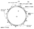
- the color code targets TA1 to TA3 include a position mark portion including a position mark P1 for indicating a measurement position as shown in FIGS.
- a reference color portion composed of a reference color mark P2 with a color used as a color reference, and a color code portion composed of a color code mark P3 with a color for identifying the color code targets TA1 to TA3.
- a mark delimiter part including delimiters for delimiting between the reference color mark P2 and the color code mark P3, between the reference color marks P2 or between the color code marks P3, and the position mark P1 and the reference color
- the mark P2 and the color code mark P3 are annularly arranged along the circumference of the circumference or regular polygon centered on the reference position C0, and the reference position 0 openings H are provided in, separated marks sandwiching a first predetermined number of the reference color mark P2, are arranged so as to sandwich the second color code marks P3 of a predetermined number.
- the position mark P1, the reference color mark P2, and the color code mark P3 included in the color code targets TA1 to TA3 may be singular or plural.
- the position mark P1 may also be used as a delimiter mark.
- a mark including a retro target is typically used as the position mark P1, but other marks such as a template mark may be used as long as the position (point) can be specified.
- three primary colors of red (R), green (G), and blue (B) are used for the reference color mark P2, but other colors may be used as long as the hue difference is equal.
- Each of the color code marks P3 has a color, and the color code portion has a distinctiveness due to a difference in color arrangement (including arrangement) of one or a plurality of color code marks P3 constituting the color code mark P3. It is preferable to include the color of the reference color mark P2 in the color of the color code mark P3 because it is easy and reliable to distinguish, but only other colors may be used. Further, it is preferable to select the hue difference of colors used for the color code mark P3 so as to be uniform in order to clarify the difference between the colors used. Also, if the circumferential width of each mark is the same, the scanning time for mark detection is the same, which is convenient for detecting the position of the mark.
- the width of the separation mark May be reduced.
- the mark is arranged in an annular shape as long as the mark is arranged around the reference position C0 in the circumferential direction, the mark is not limited to an annular shape and may be arranged in a polygonal shape.
- a ring formed by connecting marks arranged in a ring shape along the circumference or the outer periphery of a regular polygon is referred to as a mark ring.
- the hole H is typically arranged inscribed in the mark ring, but the color code target may have an inner frame region between the mark ring and the hole H. You may have an outer frame area
- the position mark P1 is annularly arranged along the circumference around the reference position C0, the reference position C0 can be easily obtained as the center of a circle connecting the position marks P1. Can do. Further, the position mark P1 can be easily detected by arranging a mark including a retro target as the position mark P1 in a predetermined position on a circular ring or the like. Further, it is possible to accurately and easily determine the color of the color code mark P3 using the reference color mark P2. In addition, the reference color mark P2 and the color code mark P3 can be easily detected by separating the reference color mark P2 and the color code mark P3 using the separation marks and arranging them at fixed positions on a ring or the like.
- a color code target can be provided.
- the position mark P1 also serves as a delimiter mark.
- the position mark P1, the reference color mark P2, and the color code mark P3 can be enlarged correspondingly, and these marks can be easily detected.
- the color code targets TA1 to TA3 according to the third aspect are the first predetermined number is 1 and the second predetermined number in the first or second aspect as shown in FIGS. 1 to 3, for example.
- the number is a constant of 2 or more.
- the color code targets TA1 to TA3 according to the fourth aspect are the same as in any of the first to third aspects, as shown in FIGS. 1 to 3, for example, according to the number of color code marks P3 and the color code.
- the number of colors used matches, and the colors of the color code marks P3 constituting the color code portion are all different.
- the identification code can be determined by confirming the color, and the reliability of the color code discrimination can be improved.
- the color code targets TA1 to TA3 according to the fifth aspect are the reference color mark P2 and the color code mark P3 in the first to fourth aspects, for example, as shown in FIGS. It is arranged in a predetermined positional relationship with respect to the position C0.
- the predetermined positional relationship typically means that the distance and direction from the reference position C0 are in a certain distance and in a certain direction. If configured in this manner, the reference color mark P2 and the color code mark P3 are arranged at fixed positions on an annular ring or the like, so that they can be easily detected.
- the color code targets TA1 to TA3 are any one of the first to fifth aspects.
- the color code targets TA1 to TA3 are composed of at least six position marks P1, Arranged so that two congruent or inverted symmetrical triangles can be extracted from the triangles formed by connecting the centers of the position marks P1.
- the position mark is 7 or more, it is sufficient if two triangles can be extracted.
- two triangles that are congruent or inversion symmetric can be extracted by connecting the center of the position mark P1 (the position of the retro target). Therefore, triangles are formed in the color code targets TA1 to TA3 being measured. It can be easily determined whether or not the point is a retro target of the position mark P1 to be obtained.
- the color code targets TA1 to TA3 according to the seventh aspect are arranged along the circumference or the outer periphery of a regular polygon in any one of the first to sixth aspects, for example, as shown in FIGS.
- the ring of marks arranged in a ring is singular. With this configuration, when the number of measurement points is relatively small (for example, 720 points or less), a color code target with a simple configuration can be used, and the mark detection and code determination processing is simplified, which is appropriate.
- the color code targets TA4 to TA7 according to the eighth aspect are arranged along the circumference or the outer periphery of a regular polygon in any of the first to sixth aspects as shown in FIGS. 12 to 15, for example.
- the number of identifiable codes can be increased by multiplication (in the case of a double ring, the number of codes in the first ring is A, When the number of codes in the second ring is B, the total number of codes is A ⁇ B, and in the case of a triple ring, the total number of codes is further increased).
- the color code targets TA1 to TA3 according to the ninth aspect are the same as the position marks P1 arranged on the ring of one mark in the seventh or eighth aspect, as shown in FIGS.
- the reference color mark P2 and the color code mark P3 are unified with the same shape and size. If comprised in this way, since the shape and dimension of each mark arrange
- the set of color code targets according to the tenth aspect is a set of color code targets configured by combining a plurality of color code targets TA according to any of the first to ninth aspects, and each color code target In the code target TA, the position mark P1, the reference color mark P2, and the color code mark P3 are arranged at the same position on the mark ring, the arrangement of the colors of the reference color mark P2 is the same, and the color of the color code mark P3 is the same. All arrangements are different. With this configuration, each color code target TA that constitutes a set of color code targets differs only in the color arrangement of the color code mark P3, so that the color code can be determined by the same processing procedure. Suitable for automating code discrimination processing.
- the symbol TA is used to generically indicate the color code target according to the present invention.
- the color code determination apparatus 1 acquires a target image acquisition unit 31 that acquires images of the color code targets TA1 to TA3 according to the first aspect from at least two different directions.
- the position mark detection unit 51 for sequentially detecting the position mark P1 from the images of the color code targets TA1 to TA3 acquired from at least two different directions by the target image acquisition unit 31, and the position mark detection unit 51 sequentially detect them.
- a reference position calculation unit 63 for obtaining a reference position C0 of the color code targets TA1 to TA3 from the arrangement of the position mark P1, and a circumference or a regular polygon outer periphery centered on the reference position C0 obtained by the reference position calculation unit 63
- a mark arrangement detector 72 for sequentially detecting marks arranged in a ring shape along the mark, and a mark arrangement
- a reference color mark extraction unit 73 that sequentially extracts the reference color mark P2 from the ring of marks detected by the detection unit 72, and a color code that sequentially extracts the color code mark P3 from the ring of marks detected by the mark arrangement detection unit 72.
- the color code mark P3 is compared with the color of each reference color mark P2 extracted by the mark extraction unit 74 and the reference color mark extraction unit 73 and the color of each color code mark P3 extracted by the color code mark extraction unit 74.
- a color code discriminating unit 75 that discriminates a color code from the arrangement of the colors, a color code that stores the reference position C0 obtained by the reference position calculating unit 63 and the color code discriminated by the color code discriminating unit 75 in association with each other.
- a storage unit 85 is compared with the color of each reference color mark P2 extracted by the mark extraction unit 74 and the reference color mark extraction unit 73 and the color of each color code mark P3 extracted by the color code mark extraction unit 74.
- “sequential extraction from the mark ring” means extraction from the designated position of the mark ring or the position determined by the design in the order of arrangement.
- the color comparison is typically made by comparing the intensity ratios of the detection light of the three primary colors, but the spectra may be compared.
- the position mark detection unit 51 detects the position mark P1 arranged in an annular shape along the circumference around the reference position C0, and the reference position calculation unit 63 detects the position mark P1. Therefore, the reference position C0 can be easily obtained using the reference position C0 as the center of a circle or the like connecting the position marks P1.
- the reference color mark P2 and the color code mark P3 arranged in an annular shape are extracted by the reference color mark extraction unit 73 and the color code mark extraction unit 74, and the colors of these marks are compared by the color code determination unit 75. Since the color code is discriminated, the color code can be discriminated accurately and easily. Therefore, it is possible to provide a color code determination apparatus suitable for determining the color code of the color code target TA according to the present invention.
- the color code discrimination device 1 detects the mark arrangement based on the arrangement of the position marks P1 sequentially detected by the position mark detection unit 51 in the eleventh aspect, for example, as shown in FIG.
- the unit 72 includes a starting point calculation unit 71 for obtaining a starting point for detecting a mark arranged in a ring shape, and the mark placement detecting unit 72 sequentially detects the mark from the starting point obtained by the starting point calculation unit 71. If comprised in this way, the starting point and order of mark detection can be determined easily, and efficient mark detection can be performed. This starting point can also be used as a starting point for the arrangement of color code marks.
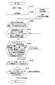
- the color code determination method includes, for example, a target image acquisition step (S100) for acquiring an image of the color code target according to the first aspect from at least two different directions, as shown in FIG.
- a position mark detection step (S110) for sequentially detecting the position mark P1 from the images of the color code targets TA1 to TA3 acquired from at least two different directions in the target image acquisition step (S100), and a position mark detection step (S110).
- a reference position calculation step (S120) for obtaining a reference position C0 of the color code targets TA1 to TA3 from the arrangement of the position marks P1 detected sequentially, and a reference position C0 obtained in the reference position calculation step (S120).
- the position mark P1 arrange
- the color code determination method according to the fourteenth aspect is based on the arrangement of the position marks P1 sequentially detected in the position mark detection process.
- a starting point calculating step (S130) for obtaining a starting point for detecting the circularly arranged marks in S140) is provided, and the mark placement detecting step (S140) sequentially detects the marks from the starting points obtained in the starting point calculating step (S130). If comprised in this way, the starting point and order of mark detection can be determined easily, and efficient mark detection can be performed.
- a color code determination apparatus and a color code determination method suitable for determining the color code of the color code target can be provided.
- FIG. 3 is a diagram illustrating an example of a color code target TA1 in Embodiment 1.
- FIG. 3 is a diagram illustrating an example of a color code target TA2 in the first embodiment.
- 6 is a diagram illustrating an example of a color code target TA3 in Embodiment 1.
- FIG. It is a figure which shows the relationship between the reference position of a color code target, and a position mark. It is a figure which shows the positional relationship between each position mark. It is a figure which shows the structural example of a color code discrimination device. It is a figure which shows the example of a processing flow of a color code discrimination method. It is explanatory drawing of the gravity center position detection using a retro target.
- FIG. 6 is a diagram illustrating an example of a color code target TA4 in Embodiment 2.
- FIG. 6 is a diagram illustrating an example of a color code target TA5 in Example 3.
- FIG. It is a figure which shows the example of the color code target TA6 in Example 4.
- FIG. It is a figure which shows the example of the color code target TA7 in Example 5.
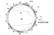
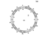
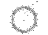
- [Color code target] 1 to 3 show examples of color code targets TA1 to TA3 in the first embodiment.
- the target is a circular shape, and a circular hole H centered on the reference position C0 is formed at the center, which is the reference position C0, and is positioned along the circumference centered on the reference position C0.
- An example in which the mark P1, the reference color mark P2, and the color code mark P3 are annularly arranged will be described.
- 1 to 3 differ in the radial width of marks arranged in an annular shape along the circumference, but the arrangement of the marks is the same. The width of the ring (ring) is small in FIG. 1, medium in FIG. 2, and large in FIG.
- the position mark P1, the reference color mark P2, and the color code mark P3 are arranged in an annular shape (ring shape) along the circumference centered on the reference position C0.
- a ring formed by connecting marks arranged in a ring along the circumference is called a mark ring (also simply called a ring).
- the color code targets TA1 to TA3 in which the marks are arranged in an annular shape are referred to as ring color targets.
- the position mark P1 is a mark indicating a measurement position
- the reference color mark P2 is a mark provided with a color used as a color reference
- the color code mark P3 is a mark provided with a color for identifying a target.
- the delimiter mark is a mark that delimits between the reference color mark and the color code mark, between the reference color marks, or between the color code marks.
- the position mark P1 also serves as a delimiter mark.
- the first predetermined number is 1 and the second predetermined number is 2.
- the inner diameter of the mark ring is determined by the outer diameter of the probe inserted into the hole and varies depending on the probe. Also, the outer diameter of the mark ring varies depending on the inner diameter. As for the ring, the width of the mark ring is preferably set so that each mark arranged along the circumference can be sufficiently recognized, for example, a width of 1 to 100 mm.
- the outer diameter of the ring is 50 mm and the inner diameter is 45 mm
- the outer diameter of the ring is 60 mm
- the inner diameter is 40 mm
- FIG. 2 and FIG. 3 a plurality of line segment marks or cross marks (which may not be present) toward the center of the circle are seen in the vicinity of the ring, but this is for making it easy to find the center.
- the position mark part is composed of one or a plurality of position marks P1.
- the position mark P1 is a mark for indicating a measurement position.
- the circular opening H is arranged at the center of the circle at the reference position C0
- the position mark P1, the reference color mark P2, and the color code mark P3 are annular along the circumference centered on the reference position C0. It is arranged in a (ring shape).
- the position mark P1 has a small and circular retroreflective function at the center of the black mark (indicated by BL in the figure) (on the symmetry line in the circumferential direction and between the inner and outer diameters in the radial direction). (Retro target) is provided.
- a small retro target preferably has a certain size or more.
- the outer diameter is about half of the radial width of the mark ring.
- the position mark P1 also serves as a delimiter mark.
- the reason for the black background is to clarify the difference from the retro target to facilitate position detection, and to clarify the separation between one or more marks as the separation marks.
- the position mark P1 includes a retro target will be described.
- a small and circular white mark formed by white coating on a black background may be used.
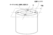
- FIG. 4 shows the relationship between the reference position C0 and the position mark P1 of the color code targets TA1 to TA3.
- the position mark P1, the reference color mark P2, and the color code mark P3 are arranged in an annular shape (ring shape) along the circumference centered on the reference position C0.
- the reference position C0 is located at the center of the circle on the plane including these marks.
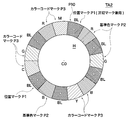
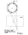
- FIG. 5 shows the positional relationship between the position marks P1.
- the position mark P10 positioned above the opening H is counted as the first, and the first triangle T1 connecting the centers of the retro targets of the first, third and thirteenth marks is positioned above the opening H.
- a second triangle T2 connecting the centers of the retro targets of the fifth, eighth and tenth marks is formed counting clockwise from the position mark P10 as the first.
- the shapes of the first triangle T1 and the second triangle T2 are congruent, and the longest side of the first triangle T1 and the longest side of the second triangle T2 are straight lines (in the horizontal direction) that divide the mark ring into upper and lower halves. (Diameter).
- each position mark P1 is arranged in a predetermined positional relationship (a fixed distance, a fixed direction) with respect to the reference position C0. Therefore, the positional relationship (distance and direction) between the first triangle T1 (vertex, side) and the second triangle T2 (vertex, side) is also constant.
- 6 position marks P1 are arranged on the ring.
- DLT Direct Linear Transformation
- 6 points on the ring position mark
- the center point of P1 can be detected with high accuracy.
- the upper three points form the first triangle T1
- the lower three points form the second triangle T2
- the shapes of the first triangle T1 and the second triangle T2 are congruent.
- the longest side of the first triangle T1 and the longest side of the second triangle T2 are arranged to face each other.
- the search is divided into the upper three points and the lower three points rather than searching for six points at once, it is only necessary to search for one triangle, and an efficient search can be performed. For example, if there are 10 candidate points, if 6 points are collectively searched, 2 triangles will be searched from a maximum of 100,000 ways, but if divided into 3 points and 3 points, the search will be 1 from a maximum of 100 ways. One triangle may be searched, and then the corresponding triangle may be searched. Corresponding triangle shapes are congruent, and the longest sides of both faces each other, so the candidate points for the search are considerably narrowed down and can be searched efficiently. The orientation and DLT method will be described later.
- the reference color part is composed of one or a plurality of reference color marks P2.
- the reference color mark P2 is a mark provided with a color to be used as a color reference. In this embodiment, red (indicated by R in the figure), green (indicated by G in the figure), and blue (indicated by B in the figure). Three colors are used.
- both sides are sandwiched between position marks (separation marks) P1, and the position mark P10 located above the opening H is first, and the second, fourth, and ninth positions are counted clockwise. Yes.
- the reference color mark P2 is used for reference during a relative comparison and for color calibration for correcting the color misregistration in order to cope with color misregistration due to photographing conditions such as illumination and a camera.
- the reference color mark P2 can be used for color correction of a color code target created by a simple method. For example, when using a color code target printed by a color printer (inkjet, laser, sublimation type printer, etc.) that is not color-controlled, individual differences appear in the color of the printer used, but the reference color mark P2 By comparing and correcting the color of the color code mark P3, the influence of individual differences can be suppressed. As described above, the color of the reference color mark P2 can be used for correcting the color of the measurement object 2 in addition to correcting the color of the color code mark P3.
- a color printer inkjet, laser, sublimation type printer, etc.
- the color code portion is composed of one or a plurality of color code marks P3.
- the color code mark P3 is a mark provided with a color for identifying the target. In this embodiment, red (indicated by R in the figure), green (indicated by G in the figure), blue (indicated by B in the figure). ), Yellow (indicated by Y in the figure), cyan (indicated by C in the figure), and magenta (indicated by M in the figure).
- Each of the two color code marks P3 is sandwiched between position marks (separation marks) P1 on both sides, and the position mark P10 located above the opening H is counted first in the clockwise direction. , 11, 12th, 14th, 15th.
- the color code mark portion expresses a code by a combination of color schemes of the color code marks constituting the color code mark portion.
- the number of codes that can be expressed varies depending on the number of code colors used for the code. For example, when the number of code colors is n, the color code target TA can represent n n codes when the number of color code marks P3 is n. In order to increase the reliability, even if the condition that the colors used for other unit marks are not used redundantly, n! Express street code. If the number of code colors is increased, the number of codes can be increased. Furthermore, if the condition that the number of color code marks P3 is equal to the number of code colors is imposed, all the code colors are used for the color code mark P3.
- the color of each color code mark P3 can be confirmed to determine the identification code, and the reliability can be improved. Furthermore, adding a condition for making the areas of the respective color code marks P3 the same is also useful when the color code target TA is detected from the image. This is because the area occupied by each color is the same even between color code targets having different identification codes, so that almost the same dispersion value is obtained from the detection light from the entire color code target TA. Further, since the boundary between the color code marks P3 is repeated at equal intervals and a clear color difference is detected, it is possible to detect the color code target TA from the image by repeating such detection light. .
- the mark delimiter is composed of multiple delimiters.
- the delimiter mark is a mark that delimits between the reference color mark P2 and the color code mark P3, between the reference color marks P2 or between the color code marks P3.
- the delimiter mark also serves as the position mark P1. It has a retro target in the center and is black (indicated by BL in the figure).
- each reference color mark P2 is sandwiched between the separator marks P1 on both sides, and two color code marks P3 are sandwiched between the separator marks P1 on both sides, resulting in the first predetermined number. Is 1, and the second predetermined number is 2.
- the delimiter mark P1 is arranged in the first, third, fifth, eighth, tenth, and thirteenth positions when the position mark P10 located above the opening H is counted first and counted clockwise.
- the first, fifth, eighth and tenth division marks counting clockwise from the position mark P10 positioned above the opening H as the first division mark between the reference color mark P2 and the color code mark P3 are 3
- the th delimiter mark is a mark that delimits the reference color marks P2
- the thirteenth delimiter mark is a mark that delimits the color code marks P3.
- a color code target TA1 to TA3 constitutes a set of color code targets
- targets having the same shape and dimensions are used for the color code targets TA1 to TA3.
- an opening H is provided at the center, and the position mark P1, the reference color mark P2, and the color code mark P3 are arranged at the same position on the ring of marks arranged in a ring shape along the circumference.
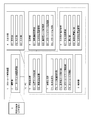
- FIG. 6 shows a configuration example of the color code discrimination device 1.
- the color code discriminating apparatus 1 includes, for example, an imaging unit 3 that captures an image of the measurement object 2, an input / output unit 4 that displays captured images and processed images, and an input / output operation.
- a feature extraction unit 5 that extracts feature points
- a three-dimensional position measurement unit 6 that measures the three-dimensional position and shape of the measurement object 2
- an image processing unit 7 that performs various image processing on the captured image, a captured image, a mark, and a measurement
- a storage unit 8 that stores a position and the like
- a color code determination device 1 and a control unit 9 that controls the respective units and functions as the color code determination device 1 are configured.
- the feature extraction unit 5, the three-dimensional position measurement unit 6, the image processing unit 7, and the control unit 9 can be realized using the functions of the personal computer PC 10 and are configured in the PC 10.
- the photographing unit 3 includes a stereo camera or a single camera for photographing the measurement object 2, and also includes a target image acquisition unit 31 that acquires images of the color code targets TA1 to TA3 from the captured image.
- the target image acquisition unit 31 acquires images from at least two different directions.
- the input / output unit 4 includes a display unit 41 that displays images and operation screens, an output unit 42 that includes a printer, a speaker, and the like, and an input unit 43 that includes a mouse, a keyboard, and the like.
- the feature extracting unit 5 sequentially detects the position mark P1 from the images of the color code targets TA1 to TA3 acquired by the target image acquiring unit 31, and extracts feature points for three-dimensional measurement from the captured image.
- a feature point extraction unit 52 is provided to extract images of the color code targets TA1 to TA3 from the captured image.
- the position mark detection unit 51 sequentially detects the position mark P1 from images acquired from at least two different directions.
- the feature points include, for example, the center position and corner position of the measurement object 2, positions having different characteristics from others, targets attached to or projected on the measurement object 2, and the like. Therefore, the position mark P1 can also be handled as one of the feature points, but here, the position mark detection unit 51 is distinguished as performing a specific process. Therefore, the feature point extraction unit 52 extracts features other than the color code target, for example, feature points for three-dimensional measurement in the measurement object 2.
- the three-dimensional measuring unit 6 searches for a corresponding point corresponding to a feature point in one image (reference image) from a captured image that forms a stereo pair in the other image (search image) (in the case of a color code target, identification is performed).
- a corresponding point search unit 61 that searches for the same corresponding point (such as a retro target of the position mark P1) based on the color code that has been recorded, an orientation unit 62 that obtains the position and inclination of the camera in the stereo image, and a position mark detection
- the reference point calculation unit 63 for obtaining the three-dimensional coordinates of the reference position C0 of the color code targets TA1 to TA3 from the arrangement of the position mark P1 sequentially detected by the unit 51, and the feature points (corresponding to the correspondence points search unit 61)
- a three-dimensional coordinate calculation unit 64 for obtaining the three-dimensional coordinates of the point) and the camera position.
- the position mark can also be handled by including it as a feature point (measurement point), here, the
- the image processing unit 7 sequentially detects marks arranged in a ring shape along the circumference centered on the reference position C0 obtained by the reference position calculation unit 63 and a starting point calculation unit 71 for obtaining a starting point for detecting the mark.
- the color code mark extraction unit 74 that sequentially extracts P3 and the color of each reference color mark P2 extracted by the reference color mark extraction unit 73 are compared with the color of each color code mark P3 extracted by the color code mark extraction unit 74.
- the storage unit 8 stores a captured image storage unit 81 that stores captured images, a reference position C0, and a three-dimensional position storage unit 82 that stores three-dimensional position coordinates of measurement points (including the center of the retro target of the position mark P1).
- a reference color mark storage unit 83 that stores the color data of each reference color mark P2 sequentially extracted by the color mark extraction unit 73, and the color data of each color code mark P3 that is sequentially extracted by the color code mark extraction unit 74 are stored.
- the color code mark storage unit 84 includes a color code storage unit 85 that stores the reference position C0 obtained by the reference position calculation unit 63 and the color code P3 determined by the color code determination unit 75 in association with each other.
- the color code discriminating unit 75 has a color-code correspondence table that records the correspondence between the color data, each reference color, and each color code color, and a plurality of types of color code targets to be used. For TA, the type code number indicating the type of the color code target TA is recorded, and for each color code target TA, the correspondence between the mark arrangement (color arrangement, that is, single color code arrangement) and the target code number is shown. It has a color code target correspondence table to be recorded, and is used for color code discrimination.
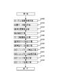
- FIG. 7 shows a processing flow example (outline) of the color code discrimination method for the color code targets TA1 to TA3.
- the target image acquisition unit 31 acquires images of the color code targets TA1 to TA3 (target image acquisition step: S100). In this embodiment, images from at least two different directions are acquired.
- the position mark detection unit 51 sequentially detects the position mark P1 from the images of the color code targets TA1 to TA3 acquired in the target image acquisition step (S100) (position mark detection step: S110). In this embodiment, the position mark P1 is sequentially detected from images acquired from at least two different directions.
- the reference position calculation unit 63 obtains the reference position C0 of the color code targets TA1 to TA3 from the arrangement of the position marks P1 sequentially detected in the position mark detection process (S110) (reference position calculation process: S120). .
- the starting point calculation unit 71 obtains a starting point for detecting the mark from the arrangement of the position marks P1 (starting point calculating step: S130).
- the mark arrangement detection unit 72 sequentially detects marks arranged in an annular shape along the circumference centered on the reference position C0 obtained in the reference position calculation step (S120) (mark arrangement detection). Step: S140).
- the reference color mark extraction unit 73 sequentially extracts the reference color mark P2 from the mark ring detected in the mark arrangement detection step (S140) (reference color mark extraction step: S150), and the reference color mark storage unit.
- the color data of each reference color mark P2 extracted sequentially is stored (reference color mark storage step: S155).
- the color code mark extraction unit 74 sequentially extracts the color code mark P3 from the mark ring detected in the mark arrangement detection step (S140) (color code mark extraction step: S160), and the color code mark storage unit.
- the color data of each color code mark P3 extracted sequentially is stored (color code mark storage step: S165).
- the color code discriminating unit 75 calculates the color of the reference color mark P2 extracted in the reference color mark extraction step (S150) and the color of the color code mark P3 sequentially extracted in the color code mark extraction step (S160). In comparison, the color code is determined from the color arrangement of the color code mark P3 (color code determination step: S170).
- the color code storage unit 85 stores the reference position C0 obtained in the reference position calculation step (S120) and the color code determined in the color code determination step (S170) in association with each other (color code storage). Step: S180).
- the position mark detection step (S110) six position marks P1 arranged on the ring are searched and detected. A retro target or a white target is used at the center of the position mark P1. Since the color code portion P3 of the color code target TA has a feature that a large number of code colors are used and the color dispersion value is large, a portion having a large dispersion value of the color code portion P3 is found from the image. Thus, the color code target TA can be detected. Thereafter, the retro target of the position mark P1 may be detected within the range of the color code target TA. In the reference position mark calculation step (S120), the reference position C0 of the color code targets TA1 to TA3 is obtained from the arrangement of the position marks sequentially detected in the position mark detection step (S110).
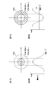
- FIG. 8 is an explanatory diagram of detecting the center of gravity using a retro target.
- the process is the same for a white circular target formed with white paint on a black background instead of a retro target.
- the retro target is formed by two concentric circles, but the outer side is not necessarily a circle.
- FIG. 8A1 the brightness of the inner circle portion 204 that is the inner side of the small circle among the concentric circles is bright, and the brightness of the outer circle portion 206 that is an annular portion formed between the small circle and the great circle is dark.
- the retro target 200, FIG. 8 (A2) is a brightness distribution diagram in the diameter direction of the retro target 200 of (A1), and FIG.
- FIG. 8 (B1) is a retro target in which the brightness of the inner circle portion 204 is dark and the brightness of the outer circle portion 206 is bright.
- 200 and FIG. 8 (B2) show the brightness distribution diagram in the diameter direction of the retro target 200 of (B1).
- the retro target is bright as shown in FIG. 8 (A1), the light intensity distribution of the image is high because the reflected light at the center of gravity is large and bright in the captured image of the measurement object 2.
- FIG. 8A2 it is possible to determine the inner circle portion 204 and the center position of the retro target from the threshold value To of the light amount distribution.
- the small circle which shows a center position is provided in the center of two concentric circles, the small dip has arisen in the center of a brightness distribution map.
- the barycentric position is calculated by, for example, the moment method. For example, assume that the plane coordinates of the retro target 200 shown in FIG. 8A1 are (x, y). Then, (Expression 1) and (Expression 2) are calculated for points in the x and y directions where the brightness of the retro target 200 is greater than or equal to the threshold value To (* is a multiplication operator).
- feature points are extracted by the feature extraction unit 5 (here, the position mark P1 is detected) using images taken from at least two directions as a stereo pair, and are determined by the color code determination unit 75.
- the corresponding point of the code identified by the corresponding point search unit 61 (such as a retro target of the position mark P1) is obtained
- the orientation unit 62 obtains the position and inclination of the camera by orientation
- the 3D position computation unit 64 (Here, the reference position calculation unit 63) obtains the three-dimensional position coordinates.
- a stereo method is typically used to calculate the three-dimensional position coordinates.
- feature points are extracted by the feature extraction unit 5 using images taken with a stereo camera or images taken from at least two directions as stereo pairs.
- the search unit 61 searches for corresponding points
- the orientation unit 62 obtains the position and tilt of the camera by orientation
- the 3D position computation unit 64 obtains 3D position coordinates.
- FIG. 9 shows an example of a processing flow mainly for detecting the mark arrangement of the color code target.
- FIG. 5 for the mark arrangement detection. Please refer to FIG. 7 in a timely manner.
- S210 all candidates for the position mark P1 of the color code targets TA1 to TA3 are detected (S210).
- the coordinates of the position mark P1 are detected by a small circular retro target at the center.
- the range is not limited to one color code target TA, and all measured ranges are detected.
- This step corresponds to the position mark detection step (S110). Details of this step are as described in FIG.
- all triangles (candidates for the first triangle T1 and the second triangle T2) are detected from the position mark candidates detected in (S210) (S220).
- the candidates for the triangles to be obtained are determined. Exclude those that do not. If it can be regarded as a candidate of the triangle (first triangle T1 or second triangle T2) to be obtained from the length of the sides of the triangle and the angle formed by the two sides, the candidate of the first triangle T1 or the second triangle T2 And decide. Subsequently, from the triangles (candidates T1 and T2) detected in (S220), the corresponding triangles (the shapes are congruent and have the longest sides facing each other) are detected, and the color code target (ring color code) is detected.
- the positional relationship between the first triangle T1 (vertex, side) and the second triangle T2 (vertex, side) is also a fixed relationship (distance and direction (direction)). If it can be regarded as the first triangle T1 and the corresponding second triangle T2 to be obtained from this relationship, 6 as the center of the position mark P1 located at the apex of the formed first triangle T1 and second triangle T2. Detect points.
- the positions of the six points at the center of the position mark P1 are confirmed by using the single photograph orientation or the DLT method or by combining the DLT method and the bundle adjustment (S240).
- This step corresponds to the latter stage of the reference position calculation step (S120). It is confirmed whether or not the six points detected as the center of the position mark P1 of the color code target TA are arranged at the designed position of the color code target (ring color code target) TA, and whether or not the triangle is to be obtained. Confirm.
- the calculation of the DLT method and the bundle adjustment is performed by, for example, the three-dimensional position calculation unit 64, and the reference position calculation unit 63 obtains the calculation result.
- the three-dimensional DLT (Direct Linear Transformation) method is a method of reconstructing the positions of marks measured from various directions into three-dimensional coordinates using two or more cameras based on the principle of triangulation.
- the DLT method approximates the relationship between the photograph coordinates and the three-dimensional coordinates (target point coordinates) of the subject by a cubic projective transformation equation.
- the basic expression of the DLT method is (Expression 3-1). If the denominator is deleted from (Equation 3-1), the following line form can be derived.
- equation 3-3 By solving (Equation 3-3) directly using the least square method, eleven unknown variables L 1 to L 11 that determine the relationship between the photographic coordinates and the target point coordinates can be acquired.
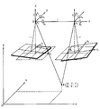
- FIG. 10 is a diagram for explaining confirmation of the position mark P1 by the DLT method.
- eleven unknown variables L 1 to L 11 are known, the relationship between the photographic coordinates (x, y) (CCD plane) and the object point coordinates (X, Y, Z) is known, and the photographic coordinates (x, The position and direction (0, 0, 0, ⁇ , ⁇ , ⁇ ) of the camera on the line connecting y) and the target point coordinates (X, Y, Z) are obtained.
- the position mark P1 is known from the design data (there are six points on the ring), so the color code target TA (ring color code target) obtained for the six points detected as the position mark P1. ) Can be determined.
- a model image refers to a three-dimensional image obtained when a subject is reproduced from two or more three-dimensional photographs. Forming relatively similar model images is called relative orientation. That is, the relative orientation determines the position and inclination of the projection center of each of the left and right cameras so that two corresponding light beams of the stereoscopic photograph meet.
- FIG. 11 is a diagram for explaining relative orientation. Next, the details of the orientation calculation of each model image will be described. By this calculation, the positions of the left and right cameras (three-dimensional coordinates and three-axis tilt) are obtained. The parameters relating to the positions of these cameras are obtained by the following coplanar conditional expression.
- the origin of the model coordinate system is taken as the left projection center, and the line connecting the right projection centers is taken as the X axis.
- the base line length is taken as the unit length.
- the parameters to be obtained at this time are the rotation angle ⁇ 1 of the left camera, the rotation angle ⁇ 1 of the Y axis, the rotation angle ⁇ 2 of the right camera, the rotation angle ⁇ 2 of the Y axis, and the rotation of the X axis. the five of the rotation angle of the corner ⁇ 2. In this case, since the rotation angle ⁇ 1 of the X axis of the left camera is 0, it is not necessary to consider.
- unknown parameters are obtained by the following procedure.
- the bundle adjustment is performed in order to appropriately match the position coordinates of the measurement points between the plurality of captured images.
- the collinear conditional expression that is a basic expression for bundle adjustment that the projection center, the photographic image, and the measurement object are in a straight line is as follows.
- the starting point calculating unit 71 determines a starting point for detecting the mark from the arrangement of the position marks P1.
- the position mark P10 that belongs to the first triangle T1 connecting the position marks P1 and is located above the opening H can be determined as the detection starting point.
- the starting point is not limited to the position mark P10 located above the opening H.
- the position mark P10 located above the opening H, which is located to the right of the reference position C0 is counted 4 in the clockwise direction.
- the second reference color mark may be used as the starting point.
- the color code target (ring color code target) TA1 to TA3 is to be obtained from the detected color arrangement of the ring, and the reference color and the color code color are compared (S250).
- This process extends from the mark arrangement detection process (S140) to the color code mark storage process (S165).
- the mark arrangement detection step (S140) marks arranged in an annular shape along the circumference centered on the reference position C0 are sequentially detected. For example, the position mark P10 located above the aperture H is scanned as a detection starting point, and the color data of the reference color mark P2, the color code mark P3, and the position mark P1 arranged on the ring is collected. To do.
- the position coordinates of the reference color mark P2 and the color code mark P3 are converted according to the design values of the color code targets TA1 to TA3 (for example, affine conversion). And ask. Then, it is checked whether or not the obtained positions of the reference color mark P2 and the color code mark P3 are colored as designed.
- the reference color mark P2 is the position mark P10 located above the opening H, and the position mark P10 is counted as the first, and the second, fourth, and ninth marks are red, green, and blue as position marks.
- the color code mark P3 is sandwiched between P1, and the color code mark P3 is counted in the sixth, seventh, eleventh, twelfth, fourteenth, fifteenth, six colors, counting clockwise from the position mark P10 positioned above the opening H.
- Two marks are arranged so as to be sandwiched between position marks P1 as separation marks.
- the arrangement of the colors (six colors) of the color code mark P3 changes variously. Therefore, in the reference color mark extraction step (S150), the position mark P10 located above the aperture H is counted as the first from the color data collected by scanning the ring, and the second, fourth, and ninth positions are counted clockwise. Are sequentially extracted.
- the color data of each reference color mark P2 extracted sequentially is stored in the reference color mark storage unit 83. Further, in the color code mark extraction step (S160), the position mark P10 located above the aperture H is counted first from the color data collected by scanning the ring and counted 6, 7, 11, The 12th, 14th, and 15th color data are sequentially extracted. In the color code mark storage step (S165), the color data of each color code mark P3 extracted sequentially is stored in the color code mark storage unit 84. The scan route is collated with the converted position data (for example, affine transformation).
- the collected color data is the color of the reference color mark P2, color code mark P3, and position mark P1 of the color code targets TA1 to TA3. It can be determined that the data. The determination is made, for example, after the color code is extracted in the color code mark extraction step (S160). Further, the hue distance of the reference color of the reference color mark P2 is compared and checked. Further, the hue distances of the six colors of the color code mark P3 are compared and checked. In this way, it is checked whether or not the color code targets TA1 to TA3 (ring color code targets) to be obtained from these color schemes. If they are different, the process returns to (S230) to check another triangle. If it is determined that the color code targets TA1 to TA3 are to be obtained, the process proceeds.
- the color code is determined (S260). This step corresponds to the color code discrimination step (S170).
- a code is read from the color scheme of the color code mark P3 to determine the color code.
- the color code discriminating unit 75 counts the color data (hue, hue) of the sixth, seventh, eleventh, twelfth, fourteenth and fifteenth color code marks P3 counting clockwise from the position mark P10 positioned above the opening H as the first. Saturation, lightness) is counted clockwise with the position mark P10 positioned above the aperture H as the first color data (hue, saturation, lightness) of the second, fourth, and ninth reference color marks P2.
- each color code mark P3 is red, yellow, green, cyan, blue, or magenta.
- all code colors are used for the color code mark P3. Therefore, not only the comparison with the reference color mark P2, but also the color code. Reliability can be improved by relatively comparing colors between the marks P3.
- the color of the reference color mark P2 can be used for correcting the color of the measurement object 2 in addition to correcting the color of the color code mark P3.
- the color code determination unit 75 converts the color data into a color code using the color-code correspondence table and the color code target correspondence table.
- the color array data is converted into a color code.
- labeling is performed (S270).
- This step corresponds to the color code storing step (S180). That is, the determined color code is stored in the color code storage unit 85 in association with the reference position (center) C0 of the color code targets TA1 to TA3 (S270). As a result, the color code is attached to the reference position of the color code targets TA1 to TA3 as a label. If other triangle combinations (candidates for T1 and T2) to be searched remain, the process returns to (S230), and these combinations are similarly processed. This substantially searches for the other color code targets TA1 to TA3. If not, complete the process.
- the hole when the hole is provided at the center of the color code target, it is easy to measure the reference position of the target, and the color code mark can be easily detected and the color code can be easily distinguished.
- a color code determination apparatus and a color code determination method suitable for determining the color code of the color code target can be provided.
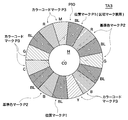
- FIG. 12 shows an example of the color code target TA4 in the second embodiment.
- Example 1 there was one ring (ring), but Example 2 shows an example in which the ring is double.
- the inner ring is the same as in Example 1, but another ring is provided on the outer side.
- the arrangement of the reference color mark P2 and the color code mark P3 in the circumferential direction is the same as that of the inner ring, and the color arrangement order of the color code mark P3 is changed.
- the reference position C0 and the opening H are the same as those in the first embodiment, and when the opening is provided at the center of the color code target, it is easy to measure the reference position of the target. It is possible to provide a color code target that can be easily discriminated.
- FIG. 13 shows an example of the color code target TA5 in the third embodiment.
- the position mark P1 is provided on the inner ring, but in the third embodiment, the position mark P1 is provided across the inner and outer rings.
- the position mark P1 can be enlarged and easily detected.
- the arrangement of the position mark P1, the reference color mark P2, and the color code mark P3 is the same as in Example 2, and when the hole is provided at the center of the color code target, the measurement of the reference position of the target is easy.
- a color code target that can easily detect a color code mark and determine a color code can be provided.
- FIG. 14 shows an example of the color code target TA6 in the fourth embodiment.
- two circular rings are separated by a black region. Thereby, two circular rings can be clearly distinguished. Therefore, it is possible to reduce errors in the circular scan.
- the arrangement of the position mark P1, the reference color mark P2, the color code mark P3, and the delimiter mark P4 is the same as that in the second embodiment, and when the hole is provided at the center of the color code target, the reference position of the target is measured. It is easy to provide a color code target that can easily detect a color code mark and distinguish a color code.
- FIG. 15 shows an example of the color code target TA7 in the fifth embodiment.
- the position mark P1 is provided on the inner ring, but in the fifth embodiment, the position mark P1 is provided across the inner and outer rings.
- the position mark P1 can be enlarged and easily detected.
- the arrangement of the position mark P1, the reference color mark P2, and the color code mark P3 is the same as in Example 2, and when the hole is provided at the center of the color code target, the measurement of the reference position of the target is easy.
- a color code target that can easily detect a color code mark and determine a color code can be provided.
- the marks are annularly arranged along the circumference centered on the reference position.
- the marks may be annularly arranged along the outer periphery of the regular polygon.
- the reference color is 3 colors and the color code color is 6 has been described, but it is sufficient that the reference color is 1 color or more and the color code color is 2 colors or more, and the number of reference color marks is 1 or more.
- the number of color code marks may be one or more. When the number of color code marks is 1, the reference color mark and the color code mark can be distinguished from each other by changing the circumferential or radial width. The greater the number of color code colors, the greater the number of codes that can be used.
- the reference number of colors typically uses three primary colors of light, but can be changed according to the number of color code colors.
- the number of mark rings is single or double has been described, but it may be triple or more.
- the greater the number of rings the greater the number of codes that can be used, and the smaller the number, the simpler the configuration and the easier the processing.
- the reference color mark may be arranged in the inner ring and the color code mark may be arranged in the outer ring for distinction.
- the opening H is described as being inscribed in the mark ring.
- the color code target may have an inner frame region between the mark ring and the opening. The outer frame region may be provided outside the mark ring.
- the center of the opening is the reference position and coincides with the center of the color code target. However, it may be decentered to some extent from the center of the color code target.
- two triangles with congruent arrangement of position marks can be extracted has been described.
- two inverted symmetrical triangles may be extracted.
- two triangles corresponding to a plurality of color code targets in the measurement range may be extracted.
- the color code identification device may have a simplified configuration by omitting, for example, the input unit, the output unit, the starting point calculation unit, the corresponding point search unit, the orientation unit, and the like.
- the order of the steps can be changed. For example, the collection of color data from the mark ring may be performed before the calculation of the starting point. After the mark arrangement detection step, the mark extraction step You may collect again.
- the example in which the determination whether the color data collected by scanning on the ring matches the design data is performed in the color code mark extraction process, but in the mark arrangement detection process.
- Color data may be collected and performed. Either the reference color mark extraction step or the color code mark extraction step may be performed first.
- the outer shape of the mark (4, 6, octagonal shape, etc.), the number of marks sandwiched between the separator marks, the number of color code colors, the number of color code marks, and the like can be appropriately changed.
- the present invention is used for various three-dimensional measurements.
- it is used for three-dimensional measurement in which multi-point measurement is performed by providing an aperture through which a prober or the like is passed.
Landscapes
- Physics & Mathematics (AREA)
- General Physics & Mathematics (AREA)
- Engineering & Computer Science (AREA)
- Radar, Positioning & Navigation (AREA)
- Remote Sensing (AREA)
- Length Measuring Devices By Optical Means (AREA)
Priority Applications (1)
| Application Number | Priority Date | Filing Date | Title |
|---|---|---|---|
| CN201080038559.3A CN102597698B (zh) | 2009-08-31 | 2010-08-17 | 色码靶、色码辨别装置及色码辨别方法 |
Applications Claiming Priority (2)
| Application Number | Priority Date | Filing Date | Title |
|---|---|---|---|
| JP2009200901A JP5350943B2 (ja) | 2009-08-31 | 2009-08-31 | カラーコードターゲット、カラーコード判別装置及びカラーコード判別方法 |
| JP2009-200901 | 2009-08-31 |
Publications (1)
| Publication Number | Publication Date |
|---|---|
| WO2011024674A1 true WO2011024674A1 (ja) | 2011-03-03 |
Family
ID=43627779
Family Applications (1)
| Application Number | Title | Priority Date | Filing Date |
|---|---|---|---|
| PCT/JP2010/063881 Ceased WO2011024674A1 (ja) | 2009-08-31 | 2010-08-17 | カラーコードターゲット、カラーコード判別装置及びカラーコード判別方法 |
Country Status (3)
| Country | Link |
|---|---|
| JP (1) | JP5350943B2 (enExample) |
| CN (1) | CN102597698B (enExample) |
| WO (1) | WO2011024674A1 (enExample) |
Cited By (2)
| Publication number | Priority date | Publication date | Assignee | Title |
|---|---|---|---|---|
| JP2020529076A (ja) * | 2017-07-28 | 2020-10-01 | ザ コカ・コーラ カンパニーThe Coca‐Cola Company | 循環記号コードを符号化及び復号する方法及び装置 |
| CN112525176A (zh) * | 2020-12-04 | 2021-03-19 | 北京天远三维科技股份有限公司 | 光学测量参考装置 |
Families Citing this family (5)
| Publication number | Priority date | Publication date | Assignee | Title |
|---|---|---|---|---|
| JP6537262B2 (ja) * | 2014-12-10 | 2019-07-03 | ワム・システム・デザイン株式会社 | カラーコード、カラーコード読取装置、カラーコード読取方法、及びプログラム。 |
| JP6854164B2 (ja) * | 2017-03-22 | 2021-04-07 | 株式会社トプコン | 測量データ処理装置、測量データ処理方法、測量データ処理システムおよび測量データ処理用プログラム |
| JP6796120B2 (ja) * | 2018-10-17 | 2020-12-02 | 川田テクノロジーズ株式会社 | 建て入れ誤差計測装置 |
| JP7313998B2 (ja) | 2019-09-18 | 2023-07-25 | 株式会社トプコン | 測量データ処理装置、測量データ処理方法および測量データ処理用プログラム |
| CN119048617B (zh) * | 2023-07-11 | 2025-06-17 | 荣耀终端股份有限公司 | 显示颜色的方法及电子设备 |
Citations (4)
| Publication number | Priority date | Publication date | Assignee | Title |
|---|---|---|---|---|
| JP2004220510A (ja) * | 2003-01-17 | 2004-08-05 | Minolta Co Ltd | 三次元形状測定装置、三次元形状測定方法及びターゲットマーク |
| JP2007003233A (ja) * | 2005-06-21 | 2007-01-11 | Ritsumeikan | コードターゲット、コード検出システム、及び3次元情報取得システム |
| JP2007107958A (ja) * | 2005-10-12 | 2007-04-26 | Oura Kosoku Kk | 測定用治具 |
| JP2009139197A (ja) * | 2007-12-05 | 2009-06-25 | Topcon Corp | カラーコード付き標識、カラーコード抽出手段及び三次元計測システム |
Family Cites Families (3)
| Publication number | Priority date | Publication date | Assignee | Title |
|---|---|---|---|---|
| US6009234A (en) * | 1995-04-14 | 1999-12-28 | Kabushiki Kaisha Toshiba | Method of reproducing information |
| JP4910316B2 (ja) * | 2005-06-21 | 2012-04-04 | 日本精工株式会社 | 磁気エンコーダ及び前記磁気エンコーダを備える転がり軸受ユニット |
| JP5136841B2 (ja) * | 2007-12-12 | 2013-02-06 | 株式会社デンソー | 回転電機用ブラシおよび回転電機 |
-
2009
- 2009-08-31 JP JP2009200901A patent/JP5350943B2/ja not_active Expired - Fee Related
-
2010
- 2010-08-17 CN CN201080038559.3A patent/CN102597698B/zh not_active Expired - Fee Related
- 2010-08-17 WO PCT/JP2010/063881 patent/WO2011024674A1/ja not_active Ceased
Patent Citations (4)
| Publication number | Priority date | Publication date | Assignee | Title |
|---|---|---|---|---|
| JP2004220510A (ja) * | 2003-01-17 | 2004-08-05 | Minolta Co Ltd | 三次元形状測定装置、三次元形状測定方法及びターゲットマーク |
| JP2007003233A (ja) * | 2005-06-21 | 2007-01-11 | Ritsumeikan | コードターゲット、コード検出システム、及び3次元情報取得システム |
| JP2007107958A (ja) * | 2005-10-12 | 2007-04-26 | Oura Kosoku Kk | 測定用治具 |
| JP2009139197A (ja) * | 2007-12-05 | 2009-06-25 | Topcon Corp | カラーコード付き標識、カラーコード抽出手段及び三次元計測システム |
Cited By (2)
| Publication number | Priority date | Publication date | Assignee | Title |
|---|---|---|---|---|
| JP2020529076A (ja) * | 2017-07-28 | 2020-10-01 | ザ コカ・コーラ カンパニーThe Coca‐Cola Company | 循環記号コードを符号化及び復号する方法及び装置 |
| CN112525176A (zh) * | 2020-12-04 | 2021-03-19 | 北京天远三维科技股份有限公司 | 光学测量参考装置 |
Also Published As
| Publication number | Publication date |
|---|---|
| JP5350943B2 (ja) | 2013-11-27 |
| CN102597698B (zh) | 2015-03-25 |
| JP2011053030A (ja) | 2011-03-17 |
| CN102597698A (zh) | 2012-07-18 |
Similar Documents
| Publication | Publication Date | Title |
|---|---|---|
| JP5695821B2 (ja) | カラーコードターゲット、カラーコード判別装置及びカラーコード判別方法 | |
| JP5207719B2 (ja) | カラーコード付き標識、カラーコード抽出手段及び三次元計測システム | |
| JP5350943B2 (ja) | カラーコードターゲット、カラーコード判別装置及びカラーコード判別方法 | |
| JP5745178B2 (ja) | 3次元測定方法、装置及びシステム、並びに画像処理装置 | |
| US8401274B2 (en) | Image processing apparatus and method | |
| EP1770356A2 (en) | Three-dimensional measurement system with projection device | |
| JP5707185B2 (ja) | マルチカメラのキャリブレーション用全周フィールド | |
| JP4909543B2 (ja) | 三次元計測システム及びその方法 | |
| JP2010071782A (ja) | 3次元計測装置およびその方法 | |
| JP5002144B2 (ja) | 三次元計測用投影装置及びシステム | |
| US10515459B2 (en) | Image processing apparatus for processing images captured by a plurality of imaging units, image processing method, and storage medium storing program therefor | |
| EP2410290A1 (en) | Image capturing device and method for three-dimensional measurement | |
| JP2010219825A (ja) | 三次元計測用画像撮影装置 | |
| JP5771423B2 (ja) | 画像色彩補正装置及び画像色彩補正方法 | |
| JP4848166B2 (ja) | 三次元計測用投影装置及びシステム | |
| JP2005140547A (ja) | 3次元計測方法、3次元計測装置、及びコンピュータプログラム | |
| CN119915381B (zh) | 颜色检测方法和装置 | |
| CN103063139A (zh) | 尺寸检测装置及方法 | |
| JP4828195B2 (ja) | カラーコード付き標識 | |
| JP5753406B2 (ja) | カラーコード付き標識及びキャリブレーションボックス | |
| JPH09210649A (ja) | 三次元計測装置 | |
| JP2019194549A (ja) | タイヤ金型サイドプレートの検査方法 | |
| Yılmaztürk | Full-automatic self-calibration of color digital cameras using color targets | |
| CN211794627U (zh) | 一种足型扫描定位板及足型扫描系统 | |
| KR101026628B1 (ko) | 삼차원 계측시스템, 삼차원 계측방법 및 컬러코드 부착표식 |
Legal Events
| Date | Code | Title | Description |
|---|---|---|---|
| WWE | Wipo information: entry into national phase |
Ref document number: 201080038559.3 Country of ref document: CN |
|
| 121 | Ep: the epo has been informed by wipo that ep was designated in this application |
Ref document number: 10811724 Country of ref document: EP Kind code of ref document: A1 |
|
| NENP | Non-entry into the national phase |
Ref country code: DE |
|
| 122 | Ep: pct application non-entry in european phase |
Ref document number: 10811724 Country of ref document: EP Kind code of ref document: A1 |