WO2011018932A1 - Charged particle beam device and image display method - Google Patents
Charged particle beam device and image display method Download PDFInfo
- Publication number
- WO2011018932A1 WO2011018932A1 PCT/JP2010/062173 JP2010062173W WO2011018932A1 WO 2011018932 A1 WO2011018932 A1 WO 2011018932A1 JP 2010062173 W JP2010062173 W JP 2010062173W WO 2011018932 A1 WO2011018932 A1 WO 2011018932A1
- Authority
- WO
- WIPO (PCT)
- Prior art keywords
- charged particle
- particle beam
- image
- sample
- primary
- Prior art date
Links
- 239000002245 particle Substances 0.000 title claims abstract description 87
- 238000000034 method Methods 0.000 title claims description 52
- 230000004075 alteration Effects 0.000 claims description 18
- 201000009310 astigmatism Diseases 0.000 claims description 16
- 238000010894 electron beam technology Methods 0.000 claims description 13
- 238000012937 correction Methods 0.000 description 17
- 239000004973 liquid crystal related substance Substances 0.000 description 14
- 239000011521 glass Substances 0.000 description 10
- 238000012549 training Methods 0.000 description 6
- 230000009471 action Effects 0.000 description 4
- 230000008901 benefit Effects 0.000 description 4
- 238000010586 diagram Methods 0.000 description 4
- 230000004888 barrier function Effects 0.000 description 3
- 230000006870 function Effects 0.000 description 3
- 239000003086 colorant Substances 0.000 description 2
- 238000001514 detection method Methods 0.000 description 2
- 230000006872 improvement Effects 0.000 description 2
- 238000009434 installation Methods 0.000 description 2
- 230000003287 optical effect Effects 0.000 description 2
- 238000003825 pressing Methods 0.000 description 2
- 208000001692 Esotropia Diseases 0.000 description 1
- 230000001133 acceleration Effects 0.000 description 1
- 230000015572 biosynthetic process Effects 0.000 description 1
- 230000015556 catabolic process Effects 0.000 description 1
- 238000006731 degradation reaction Methods 0.000 description 1
- 230000005672 electromagnetic field Effects 0.000 description 1
- 238000002474 experimental method Methods 0.000 description 1
- 238000010884 ion-beam technique Methods 0.000 description 1
- 238000012986 modification Methods 0.000 description 1
- 230000004048 modification Effects 0.000 description 1
- 230000009467 reduction Effects 0.000 description 1
- 238000000926 separation method Methods 0.000 description 1
- 230000000007 visual effect Effects 0.000 description 1
Images


Classifications
-
- H—ELECTRICITY
- H01—ELECTRIC ELEMENTS
- H01J—ELECTRIC DISCHARGE TUBES OR DISCHARGE LAMPS
- H01J37/00—Discharge tubes with provision for introducing objects or material to be exposed to the discharge, e.g. for the purpose of examination or processing thereof
- H01J37/02—Details
- H01J37/04—Arrangements of electrodes and associated parts for generating or controlling the discharge, e.g. electron-optical arrangement, ion-optical arrangement
- H01J37/147—Arrangements for directing or deflecting the discharge along a desired path
-
- H—ELECTRICITY
- H01—ELECTRIC ELEMENTS
- H01J—ELECTRIC DISCHARGE TUBES OR DISCHARGE LAMPS
- H01J37/00—Discharge tubes with provision for introducing objects or material to be exposed to the discharge, e.g. for the purpose of examination or processing thereof
- H01J37/26—Electron or ion microscopes; Electron or ion diffraction tubes
- H01J37/28—Electron or ion microscopes; Electron or ion diffraction tubes with scanning beams
-
- H—ELECTRICITY
- H01—ELECTRIC ELEMENTS
- H01J—ELECTRIC DISCHARGE TUBES OR DISCHARGE LAMPS
- H01J37/00—Discharge tubes with provision for introducing objects or material to be exposed to the discharge, e.g. for the purpose of examination or processing thereof
- H01J37/02—Details
- H01J37/04—Arrangements of electrodes and associated parts for generating or controlling the discharge, e.g. electron-optical arrangement, ion-optical arrangement
- H01J37/147—Arrangements for directing or deflecting the discharge along a desired path
- H01J37/1478—Beam tilting means, i.e. for stereoscopy or for beam channelling
-
- H—ELECTRICITY
- H01—ELECTRIC ELEMENTS
- H01J—ELECTRIC DISCHARGE TUBES OR DISCHARGE LAMPS
- H01J37/00—Discharge tubes with provision for introducing objects or material to be exposed to the discharge, e.g. for the purpose of examination or processing thereof
- H01J37/02—Details
- H01J37/22—Optical or photographic arrangements associated with the tube
-
- A—HUMAN NECESSITIES
- A61—MEDICAL OR VETERINARY SCIENCE; HYGIENE
- A61B—DIAGNOSIS; SURGERY; IDENTIFICATION
- A61B6/00—Apparatus or devices for radiation diagnosis; Apparatus or devices for radiation diagnosis combined with radiation therapy equipment
- A61B6/02—Arrangements for diagnosis sequentially in different planes; Stereoscopic radiation diagnosis
- A61B6/022—Stereoscopic imaging
-
- G—PHYSICS
- G02—OPTICS
- G02B—OPTICAL ELEMENTS, SYSTEMS OR APPARATUS
- G02B30/00—Optical systems or apparatus for producing three-dimensional [3D] effects, e.g. stereoscopic images
- G02B30/20—Optical systems or apparatus for producing three-dimensional [3D] effects, e.g. stereoscopic images by providing first and second parallax images to an observer's left and right eyes
- G02B30/22—Optical systems or apparatus for producing three-dimensional [3D] effects, e.g. stereoscopic images by providing first and second parallax images to an observer's left and right eyes of the stereoscopic type
- G02B30/23—Optical systems or apparatus for producing three-dimensional [3D] effects, e.g. stereoscopic images by providing first and second parallax images to an observer's left and right eyes of the stereoscopic type using wavelength separation, e.g. using anaglyph techniques
-
- G—PHYSICS
- G02—OPTICS
- G02B—OPTICAL ELEMENTS, SYSTEMS OR APPARATUS
- G02B30/00—Optical systems or apparatus for producing three-dimensional [3D] effects, e.g. stereoscopic images
- G02B30/20—Optical systems or apparatus for producing three-dimensional [3D] effects, e.g. stereoscopic images by providing first and second parallax images to an observer's left and right eyes
- G02B30/26—Optical systems or apparatus for producing three-dimensional [3D] effects, e.g. stereoscopic images by providing first and second parallax images to an observer's left and right eyes of the autostereoscopic type
- G02B30/27—Optical systems or apparatus for producing three-dimensional [3D] effects, e.g. stereoscopic images by providing first and second parallax images to an observer's left and right eyes of the autostereoscopic type involving lenticular arrays
-
- G—PHYSICS
- G02—OPTICS
- G02B—OPTICAL ELEMENTS, SYSTEMS OR APPARATUS
- G02B30/00—Optical systems or apparatus for producing three-dimensional [3D] effects, e.g. stereoscopic images
- G02B30/20—Optical systems or apparatus for producing three-dimensional [3D] effects, e.g. stereoscopic images by providing first and second parallax images to an observer's left and right eyes
- G02B30/26—Optical systems or apparatus for producing three-dimensional [3D] effects, e.g. stereoscopic images by providing first and second parallax images to an observer's left and right eyes of the autostereoscopic type
- G02B30/30—Optical systems or apparatus for producing three-dimensional [3D] effects, e.g. stereoscopic images by providing first and second parallax images to an observer's left and right eyes of the autostereoscopic type involving parallax barriers
- G02B30/31—Optical systems or apparatus for producing three-dimensional [3D] effects, e.g. stereoscopic images by providing first and second parallax images to an observer's left and right eyes of the autostereoscopic type involving parallax barriers involving active parallax barriers
-
- H—ELECTRICITY
- H01—ELECTRIC ELEMENTS
- H01J—ELECTRIC DISCHARGE TUBES OR DISCHARGE LAMPS
- H01J2237/00—Discharge tubes exposing object to beam, e.g. for analysis treatment, etching, imaging
- H01J2237/26—Electron or ion microscopes
- H01J2237/2611—Stereoscopic measurements and/or imaging
-
- H—ELECTRICITY
- H01—ELECTRIC ELEMENTS
- H01J—ELECTRIC DISCHARGE TUBES OR DISCHARGE LAMPS
- H01J37/00—Discharge tubes with provision for introducing objects or material to be exposed to the discharge, e.g. for the purpose of examination or processing thereof
- H01J37/02—Details
- H01J37/04—Arrangements of electrodes and associated parts for generating or controlling the discharge, e.g. electron-optical arrangement, ion-optical arrangement
- H01J37/153—Electron-optical or ion-optical arrangements for the correction of image defects, e.g. stigmators
Definitions
- the present invention relates to a charged particle beam apparatus and an image display method thereof, and more particularly to a method for constructing a three-dimensional image in a charged particle beam apparatus having a stereo pair image observation function.
- a charged particle beam apparatus typified by a scanning electron microscope
- two images acquired from different directions of the left-eye image and the right-eye image are used and the two images are alternately displayed.
- Cited document 1 or using a crossing method, a parallel method, or an anaglyph method using red-blue glasses.
- Patent Document 2 As a method of obtaining a tilted image of a sample by tilting a charged particle beam with respect to the sample (Patent Document 2) and a three-dimensional image display method, a three-dimensional liquid crystal display has been developed and can be applied to three-dimensional observation. Developed in each technical field.
- a stereoscopic image is constructed from parallax images only in one axial direction (for example, X direction) at an equal angle (for example, ⁇ 3 °) from the center of the optical axis. Only the stereoscopic images that were seen could be obtained.
- each of the stereoscopic observation methods has the following characteristics, and it cannot be generally determined which observation method is superior.
- the crossing method and the parallel method do not require special tools and can be viewed stereoscopically with the naked eye, but they are not suitable for normal operation, require training, and many operators are not good at either.
- the anaglyph method allows stereoscopic observation without the need for training, but it requires red and blue glasses at all times, so it is unsuitable for normal operation and has problems such as a decrease in luminance due to a color filter.
- a stereoscopic liquid crystal display does not require training and can be stereoscopically observed with the naked eye, so that it is not likely to interfere with normal operation, but it requires installation space and is expensive.
- each observation method has advantages and disadvantages, and there are advantages and disadvantages depending on the operator. Therefore, ease of use is improved if a stereoscopic observation method can be freely selected.
- An object of the present invention is to provide acquisition means for acquiring left and right parallax images not only from an upper direction but also from an oblique direction in a charged particle beam apparatus. It is another object of the present invention to provide a parallax image display unit and an operation screen that can switch a stereoscopic observation method.
- the present invention provides a charged particle source, an objective lens that focuses a primary charged particle beam emitted from the charged particle source, a scanning deflector that scans the primary charged particle beam on a sample, and the primary charged particle beam.
- a detector for detecting signal particles generated from a sample by scanning and a charged particle beam apparatus for acquiring a sample image using the signal particles of the detector, deflection for deflecting an irradiation angle of the primary charged particle beam to the sample
- an independent first and second power source for supplying current to the deflector, and a switch for switching the two power sources in units of one line or one frame of scanning of the primary charged particle beam.
- the present invention also includes a charged particle source, an objective lens that focuses a primary charged particle beam emitted from the charged particle source, a scanning deflector that scans the primary charged particle beam on a sample, In a detector that detects signal particles generated from a sample by scanning the primary charged particle beam, and a charged particle beam apparatus that acquires a sample image using the signal particles of the detector, Applying two different voltages to the deflector that deflects the irradiation angle of the primary charged particle beam to the sample, the first image and the second image are obtained, the first image and A display device for displaying a second image is provided, and the arrangement of the first image and the second image displayed on the display device on the display device is switched.
- a charged particle beam apparatus capable of acquiring a stereoscopic image not only from above but also from an oblique direction.
- a parallax image display means and an operation screen that can switch the stereoscopic observation method can be provided, and the user can select the observation direction, the parallax angle, and the stereoscopic observation method with a single mouse operation.
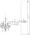
- FIG. 1 is a schematic view of a scanning electron microscope that is an example of the present invention.
- Means to tilt the beam center symmetrically without tilting.
- the structural example of the operation screen of the charged particle beam apparatus which is an example of this invention.
- An example of application of the present invention in which aberrations on a sample caused by an off-axis beam entering an objective lens are comprehensively canceled by an optical system of a multistage lens.
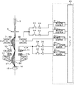
- FIG. 1 is a schematic configuration diagram of a scanning electron microscope which is an example of the present invention.
- a voltage is applied between a cathode 1 and an anode 2 constituting an electron gun 1 'serving as a charged particle source by a high voltage control power source 18 controlled by a computer 28 serving as a control unit, and a primary charged particle beam is formed.
- the electron beam 3 is extracted from the cathode 1 and further accelerated through an accelerating anode (not shown) and guided to the lens system at the subsequent stage.
- the primary electron beam 3 is focused by the first focusing lens 4 controlled by the first focusing lens control power source 19, and further focused by the second focusing lens 5 controlled by the second focusing lens control power source 20.
- the beam is guided to the beam tilt angle control coil 10 controlled by the first beam tilt angle control power supply 24.
- the beam tilt angle control coil 10 includes an upper deflection coil 10a and a lower deflection coil 10b.
- An astigmatism correction coil 8 is provided above the beam tilt angle control coil 10, and this function will be described later.
- the astigmatism correction coil 8 is current controlled by an astigmatism correction power source 23.
- the beam tilt angle control coil 10 is arranged above the objective lens 12 controlled by the objective lens control power supply 26, the beam tilt angle control coil 10 is arranged. Further, around the beam tilt angle control coil 10, a primary electron beam 3 is placed on a sample stage (illustrated). (Omitted) Two upper and lower scanning coils 11 (11a, 11b) for scanning on the sample 14 placed thereon are arranged. The scanning coil 11 is controlled by a scanning coil control power supply 25. The sample stage on which the sample 14 is placed is moved by the sample stage 15 in the XY in-plane direction or the Z direction, thereby moving the scanning region of the primary electron beam on the sample, that is, the visual field. The movement of the sample stage 15 is controlled by the stage control unit 44.
- the primary electron beam 3 is subjected to horizontal deflection current control and vertical deflection current control via the scanning coil 11 by the scanning coil control power supply 25, and two-dimensional scanning control is performed on the sample 14. Secondary electrons generated from the sample 14 by the irradiation of the primary electron beam 3 are separated from the primary electrons by an orthogonal electromagnetic field generator (not shown) for secondary electron separation and detected by the secondary electron detector 16. The signal detected by the secondary electron detector 16 is amplified by the signal amplifier 17 and then input to the computer 28 via the signal input unit 27.
- the reflected electrons of the primary electron beam 3 from the sample are also detected by the reflected electron detector 13, amplified by the signal amplifier 17, and then input to the computer 28 via the signal input unit 27.
- the reflected electrons are also processed as reflected electron images by the computer 28 and can be displayed via the display device 29.
- reference numeral 31 denotes an input device, which sets image capturing conditions (switching operation between two-dimensional observation and three-dimensional observation modes, scanning speed, acceleration voltage, etc.).
- the computer (control unit) 28 controls the current of the beam tilt angle control coil 10 and the scan coil 11 via the first beam tilt angle control power source 24 and the scan coil control power source 25, thereby realizing real time (actual). 3), the beam tilt angle control coil 10 changes the sample observation direction without performing the mechanical operation of the sample stage 15 or the like.
- a primary charged particle beam (for example, a charged particle such as an electron beam or an ion beam) is scanned on the same line in the scan on the sample so as to perform two scans, a scan with a left tilt and a scan with a right tilt corresponding to the parallax angle.
- (Line) 3 is controlled and switched in units of one line or one frame, and right and left parallax images are acquired in real time and stored in the image memory 30. That is, the computer 28 synthesizes the left tilt beam scanning image based on the secondary electron detection signal obtained by the odd number scan, that is, the left tilt primary electron beam scan, and the even number scan, that is, the right tilt primary electron beam. Based on the secondary electron detection signal obtained by scanning, a right tilt beam scanning image is synthesized. The left and right parallax images are three-dimensionally processed, and real-time three-dimensional observation is executed.
- FIG. 2 shows a means for tilting the beam symmetrically with respect to the central axis.
- Reference numeral 37 denotes a left-eye tilt beam trajectory (left tilt), and 38 denotes a right-eye tilt beam trajectory (right tilt).
- the signal from the first beam tilt angle control power supply 24 is amplified by the tilt signal amplifier 33 and switched by the tilt direction changeover switch 34 in units of one line or one frame.
- the tilt signal amplifier 33 is amplified by the tilt signal amplifier 33 and switched by the tilt direction changeover switch 34 in units of one line or one frame.
- the left tilt signal is inverted and input to the right tilt, and a plus or minus current is supplied to the beam tilt angle control coil 10 to center the beam. Tilt symmetrically about the axis.
- a second beam tilt angle control power supply 36 is newly provided, and the tilt signal amplifier 33 is used to control two independent systems, and independent control values are given to the left and right tilts.
- the first beam tilt angle control power source 24 and the second beam tilt angle control power source 36 are provided.
- the present invention is not limited to this, and the present invention can be realized by switching values with a single control power source using a DAC.
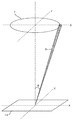
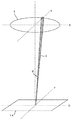
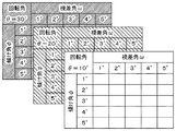
- FIGS. 4A to 4C show schematic diagrams of beam tilting according to the above-described method.
- ⁇ represents a rotation angle
- ⁇ represents a tilt angle
- ⁇ represents a parallax angle
- T represents an observation direction trajectory when the observation angle is ⁇ .
- the first beam trajectory central axis is a conventional central axis.
- ⁇ a concentric circle centered on the conventional central axis is virtually drawn, and if ⁇ is designated, the tilt direction of the beam is determined.
- the parallax angle the left-eye tilt beam trajectory 37 and the right-eye tilt beam trajectory 38 are derived, and a current corresponding to the parallax angle is supplied to the beam tilt angle control coil 10 from the direction that the user wants to observe.
- the sample 14 can be stereoscopically observed.
- FIG. 4A is a diagram in which the primary beam is tilted in the x direction by an angle ⁇ . At this time, the amount of current flowing through the x coil of the beam tilt angle control coil 10 is Ix.
- FIG. 4B is a diagram in which the primary beam is tilted in the y direction by an angle ⁇ . At this time, the amount of current flowing through the y coil of the beam tilt angle control coil 10 is defined as Iy.
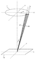
- FIG. 4C shows the case of the tilt angle ⁇ , the rotation angle ⁇ , and the parallax angle ⁇ .
- the current value passed through the right tilt is x coil: Ix ⁇ (sin ( ⁇ + ⁇ ) / sin ( ⁇ )) ⁇ cos ⁇
- y coil Iy ⁇ (sin ( ⁇ + ⁇ ) / sin ( ⁇ )) ⁇ sin ⁇ .
- the values of the current flowing at the left slope are: x coil: Ix ⁇ (sin ( ⁇ ) / sin ( ⁇ )) ⁇ cos ⁇
- y coil Iy ⁇ (sin ( ⁇ ) / sin ( ⁇ )) ⁇ sin ⁇ Become.
- the computer 28 gives the current amount stored in the control table to the beam tilt angle control coil.
- the computer 28 calculates a value using interpolation or the like.
- a method of tilting and rotating the sample stage 15 can be considered, but it takes time to set a desired position, and the observation position is also shifted.
- an advantage for example, reduction in resolution degradation due to beam tilt
- FIG. 1 shows an arrangement example of the astigmatism correction coil 8 in the present invention.
- the astigmatism correction coil 8 is arranged at a position where correction is effective and does not affect the tilt angle. Specifically, since it is necessary to arrange the beam at a position where the beam shape is easy to be formed and a position where the deflection action is unlikely to occur, the beam is arranged at an upper stage than the beam tilt angle control coil 10 before the axis is separated. As a result, astigmatism correction is also effective, and it is difficult for the deflection action to occur and the tilt angle is hardly affected.
- the astigmatism correction coil 8 can be used.
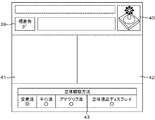
- FIG. 6 shows an operation screen of a charged particle beam apparatus which is an example of the present invention.
- a parallax angle designating part 39 and an observation direction designating part 40 By providing a parallax angle designating part 39 and an observation direction designating part 40 and specifying them, the corresponding values are called from the control table as shown in FIG. 5 and the current flowing through the beam tilt angle control coil 10 is controlled.
- the parallax angle and the viewing direction can be designated.
- Specified observation direction is not limited to the operation screen, but may be replaced by hardware such as a joystick. Further, if the beam is tilted using the operation unit as shown in FIG. 6 not only during stereoscopic observation but also during normal observation, a two-dimensional sample tilt image can be acquired instantaneously without tilting the sample stage 15. It can also be applied during normal observation.
- stereoscopic liquid crystal displays are shifting from those using dedicated glasses to methods that allow stereoscopic viewing with the naked eye.
- dedicated glasses may be used for 3D observation at all times, such as in games and media viewing.
- charged particle devices can be used for operations other than 3D observation, such as device adjustment and setting of observation conditions, and 3D observation. Since it is necessary to repeat frequently, it is troublesome to attach and detach with dedicated glasses, and stereoscopic vision with the naked eye is desired.
- image data corresponding to left and right parallax is alternately detected in units of scanning lines. Therefore, left and right viewing pixel data is recorded in the line memory for two lines, and the arrangement is converted to match the display rate of the display. Output in real time, stereoscopic viewing in real time is possible.
- the images corresponding to the left and right parallax are arranged side by side, and the three-dimensional viewing is performed by seeing the left and right view images with the corresponding eyes, which is called the crossing method or the parallel method. In this case, it is only necessary to two-dimensionally arrange image data corresponding to the left-right parallax input in units of scanning lines.
- Another method is to use red and blue glasses called anaglyphs. Colors of glasses corresponding to left and right images may be colored and superimposed on a general display.
- each of the above-described stereoscopic observation methods has the following characteristics, and which observation method is suitable depends on the observer.
- 3D liquid crystal displays do not require training, are not likely to interfere with normal operation, and can be stereoscopically observed with the naked eye, but they require installation space and are expensive.
- the crossing method and the parallel method do not require special tools and can be stereoscopically viewed with the naked eye, but they are not suitable for normal operation due to crossed eyes or distant eyes, and training is necessary, and there are many operators who are not good at either.
- the anaglyph method enables stereoscopic observation without training, red-blue glasses are always required for stereoscopic observation, and it is unsuitable for normal operation due to the removal of glasses, and there is a concern that luminance may be reduced by a color filter.
- the above-mentioned stereoscopic liquid crystal display / crossing method / parallel method / anaglyph method stereoscopic observation method selection part 43 is arranged. This may be replaced with hardware such as a switch. Specifically, a first display area 41 that can display one of the left and right parallax image data and a second display area 42 that can display the other are provided on the operation screen of the charged particle beam apparatus.
- the left and right parallax images are displayed on the same screen, for example, the right-eye image is displayed in the first display area 41, the left-eye image is displayed in the second display area 42, and the first display area 41 is displayed on the left side. If the two display areas 42 are arranged on the right side, stereoscopic observation in real time by the crossing method becomes possible.
- FIG. 6 selects the intersection method as an example.
- a coil for inclining a charged particle beam by inverting the control DAC value of the gradient current internally by pushing a parallel method switching button or physically inverting the switching timing of the inclination angle switching. If the current to be applied is reversed or the left and right scanning timings are reversed, the left-eye image is displayed in the first display area 41 and the right-eye image is displayed in the second display area 42. It becomes possible.
- the colors of the glasses corresponding to the left and right parallax images are colored and displayed in a superimposed manner, thereby enabling stereoscopic observation by the anaglyph method.
- the right and left parallax pixel data is input in accordance with the pixel arrangement (parallax barrier method, beam splitting (lenticular) method, etc.) of the stereoscopic liquid crystal display. Stereoscopic observation is possible.
- a third focusing lens (which is controlled by a third focusing lens control power source 22 below the first focusing lens 4 and the second focusing lens 5 (not shown in FIG. 7)).
- the first aberration control power source 21 and the second aberration control power source 35 are provided in the parallax angle forming electromagnetic coil 7 provided in the upper stage. If independent control is performed in two systems like the beam tilt angle control coil 10 described above and the control is interlocked with the beam tilt angle control coil 10, the off-axis aberration and third aberration of the objective lens can be obtained in a state where the present invention is executed.
- the aberration of the focusing lens (aberration correction lens) 9 can be canceled in real time, and the aberration blur caused by the off-axis can be canceled.
- the parallax angle forming electromagnetic coil 7 is not used, but only the beam tilt angle control coil 10 is used to tilt the beam. Since it is considered that the blur is removed to some extent only by the astigmatism correction coil 8 without performing the aberration cancellation, the use of the aberration cancellation and the astigmatism correction according to the situation, or both, makes it easy to use. improves. At that time, the astigmatism correction coil 8 is arranged at an upper stage than the parallax angle forming electromagnetic coil 7. While the above description has been made with reference to exemplary embodiments, it will be apparent to those skilled in the art that the invention is not limited thereto and that various changes and modifications can be made within the spirit of the invention and the scope of the appended claims.
Landscapes
- Chemical & Material Sciences (AREA)
- Analytical Chemistry (AREA)
- Analysing Materials By The Use Of Radiation (AREA)
- Testing, Inspecting, Measuring Of Stereoscopic Televisions And Televisions (AREA)
Abstract
Description
前記一次荷電粒子線の走査によって試料から発生する信号粒子を検出する検出器と、前記検出器の信号粒子を用いて試料像を取得する荷電粒子線装置において、
前記一次荷電粒子線の試料への照射角を偏向する偏向器と、当該偏向器に異なる2つの電圧を印加して、第一の画像及び第二の画像を取得し、当該第一の画像及び第二の画像を表示する表示装置を備え、当該表示装置に表示される第一の画像及び第二の画像の、前記表示装置上の配置を切り替えることを特徴とする。 The present invention also includes a charged particle source, an objective lens that focuses a primary charged particle beam emitted from the charged particle source, a scanning deflector that scans the primary charged particle beam on a sample,
In a detector that detects signal particles generated from a sample by scanning the primary charged particle beam, and a charged particle beam apparatus that acquires a sample image using the signal particles of the detector,
Applying two different voltages to the deflector that deflects the irradiation angle of the primary charged particle beam to the sample, the first image and the second image are obtained, the first image and A display device for displaying a second image is provided, and the arrangement of the first image and the second image displayed on the display device on the display device is switched.
本発明の他の目的、特徴及び利点は添付図面に関する以下の本発明の実施例の記載から明らかになるであろう。 With the above configuration, it is possible to provide a charged particle beam apparatus capable of acquiring a stereoscopic image not only from above but also from an oblique direction. Further, a parallax image display means and an operation screen that can switch the stereoscopic observation method can be provided, and the user can select the observation direction, the parallax angle, and the stereoscopic observation method with a single mouse operation.
Other objects, features and advantages of the present invention will become apparent from the following description of embodiments of the present invention with reference to the accompanying drawings.
試料上で所望の視差角を得るためには、前述公知特許でも示しているように、対物レンズ主軸から離れた位置に入射させ、レンズのビーム振り戻し作用を利用する。ところが、ビームが非点収差補正コイル8の軸外を通過すると、偏向作用が発生し、ビーム傾斜角に影響を与えてしまう。また、対物レンズ主軸に対し、離軸したビームが入射すると、対物レンズ本来の球面収差と色収差から派生すると考えられる収差ボケにより分解能が劣化する。 (Problems during off-axis deflection, astigmatism correction coil position)
In order to obtain a desired parallax angle on the sample, as shown in the aforementioned known patent, it is made incident on a position away from the main axis of the objective lens, and the beam returning action of the lens is used. However, when the beam passes off the axis of the
上記記載は実施例についてなされたが、本発明はそれに限らず、本発明の精神と添付の請求の範囲の範囲内で種々の変更および修正をすることができることは当業者に明らかである。 Further, when it is predicted that there is little aberration blur, such as when the tilt angle is shallow, the parallax angle forming electromagnetic coil 7 is not used, but only the beam tilt
While the above description has been made with reference to exemplary embodiments, it will be apparent to those skilled in the art that the invention is not limited thereto and that various changes and modifications can be made within the spirit of the invention and the scope of the appended claims.
1′ 電子銃
2 陽極
3 一次電子線
4 第1集束レンズ
5 第2集束レンズ
6 絞り板
7 視差角形成用電磁コイル
8 非点収差補正コイル
9 第3集束レンズ(収差補正レンズ)
10 ビーム傾斜角制御コイル
11 走査コイル
12 対物レンズ
13 反射電子用検出器
14 試料
15 試料ステージ
16 二次電子検出器
17 信号増幅器
18 高圧制御電源
19 第1集束レンズ制御電源
20 第2集束レンズ制御電源
21 第1収差制御電源
22 第3集束レンズ制御電源
23 非点収差補正電源
24 第1ビーム傾斜角制御電源
25 走査コイル制御電源
26 対物レンズ制御電源
27 信号入力部
28 コンピュータ
29 表示装置
30 画像メモリ
31 入力装置
32 反転入力器
33 傾斜信号増幅器
34 傾斜方向切り替えスイッチ
35 第2収差制御電源
36 第2ビーム傾斜角制御電源
37 左目用傾斜ビーム軌道
38 右目用傾斜ビーム軌道
39 視差角指定部位
40 観察方向指定部位
41 第一表示領域
42 第二表示領域
43 立体観察方法選択部位
44 ステージ制御部 DESCRIPTION OF
DESCRIPTION OF
Claims (8)
- 荷電粒子源と、
前記荷電粒子源から放出される一次荷電粒子線を集束する対物レンズと、
前記一次荷電粒子線を試料上で走査する走査偏向器と、
前記一次荷電粒子線の走査によって試料から発生する信号粒子を検出する検出器と、
前記検出器の信号粒子を用いて試料像を取得する荷電粒子線装置において、
前記一次荷電粒子線の試料への照射角を偏向する偏向器と、
当該偏向器に電流を流す独立した第一及び第二の電源を備え、
前記一次荷電粒子線の走査の一ライン単位又は一フレーム単位で、当該2つの電源を切り替えるスイッチを備えることを特徴とする荷電粒子線装置。 A charged particle source;
An objective lens for focusing a primary charged particle beam emitted from the charged particle source;
A scanning deflector for scanning the sample with the primary charged particle beam;
A detector for detecting signal particles generated from a sample by scanning the primary charged particle beam;
In a charged particle beam apparatus that acquires a sample image using signal particles of the detector,
A deflector for deflecting the irradiation angle of the primary charged particle beam to the sample;
Comprising independent first and second power supplies for passing current to the deflector;
A charged particle beam apparatus comprising: a switch that switches between the two power sources in units of one line or one frame of scanning of the primary charged particle beam. - 請求項1の荷電粒子線装置において、
前記第一の電源を印加した時の信号粒子を用いて取得した第一の試料像と、前記第二の電源を印加したときの信号粒子を用いて取得した第二の試料像を用いて、前記試料の傾斜方向からの立体像が観察可能であることを特徴とする荷電粒子線装置。 The charged particle beam apparatus according to claim 1.
Using the first sample image obtained using the signal particles when the first power source is applied and the second sample image obtained using the signal particles when the second power source is applied, A charged particle beam apparatus characterized in that a three-dimensional image from the tilt direction of the sample can be observed. - 請求項1の荷電粒子線装置において、
前記一次電子線の傾斜方向ごとに、前記偏向器に流す電流値を規定するテーブルを記憶することを特徴とする荷電粒子線装置。 The charged particle beam apparatus according to claim 1.
A charged particle beam apparatus characterized by storing a table for defining a current value to be passed through the deflector for each inclination direction of the primary electron beam. - 請求項1の荷電粒子線装置において、
前記偏向器より荷電粒子源側に、一次荷電粒子の非点収差を補正する非点収差補正器を備えたことを特徴とする荷電粒子線装置。 The charged particle beam apparatus according to claim 1.
A charged particle beam apparatus comprising an astigmatism corrector for correcting astigmatism of primary charged particles closer to the charged particle source than the deflector. - 請求項1の荷電粒子線装置において、
前記荷電粒子線装置は、前記偏向器より荷電粒子源側に集束レンズを備え、
前記対物レンズで発生する軸外収差を当該集束レンズで相殺することを特徴とする荷電粒子線装置。 The charged particle beam apparatus according to claim 1.
The charged particle beam device includes a focusing lens closer to the charged particle source than the deflector,
A charged particle beam apparatus characterized in that off-axis aberrations generated in the objective lens are canceled out by the focusing lens. - 荷電粒子源と、
前記荷電粒子源から放出される一次荷電粒子線を集束する対物レンズと、
前記一次荷電粒子線を試料上で走査する走査偏向器と、
前記一次荷電粒子線の走査によって試料から発生する信号粒子を検出する検出器と、
前記検出器の信号粒子を用いて試料像を取得する荷電粒子線装置において、
前記一次荷電粒子線の試料への照射角を偏向する偏向器と、
当該偏向器に異なる2つの電圧を印加して、第一の画像及び第二の画像を取得し、当該第一の画像及び第二の画像を表示する表示装置を備え、
当該表示装置に表示される第一の画像及び第二の画像の、前記表示装置上の配置を切り替えることを特徴とする荷電粒子線装置。 A charged particle source;
An objective lens for focusing a primary charged particle beam emitted from the charged particle source;
A scanning deflector for scanning the sample with the primary charged particle beam;
A detector for detecting signal particles generated from a sample by scanning the primary charged particle beam;
In a charged particle beam apparatus that acquires a sample image using signal particles of the detector,
A deflector for deflecting the irradiation angle of the primary charged particle beam to the sample;
A display device that applies two different voltages to the deflector to acquire a first image and a second image, and displays the first image and the second image;
A charged particle beam device, wherein the arrangement of the first image and the second image displayed on the display device is switched on the display device. - 請求項6の荷電粒子線装置において、
前記荷電粒子線装置は、交差法、立体法、アナグリフ法、に応じて第一の画像及び第二の画像の配置を切り替えることを特徴とする荷電粒子線装置。 In the charged particle beam device according to claim 6,
The charged particle beam apparatus switches the arrangement of the first image and the second image according to an intersection method, a three-dimensional method, and an anaglyph method. - 請求項6の荷電粒子線装置において、
前記第一の画像と第二の画像を用い、立体表示ディスプレイに立体像を形成することを特徴とする荷電粒子線装置。 In the charged particle beam device according to claim 6,
A charged particle beam device that forms a stereoscopic image on a stereoscopic display using the first image and the second image.
Priority Applications (5)
| Application Number | Priority Date | Filing Date | Title |
|---|---|---|---|
| DE112010002918.0T DE112010002918B4 (en) | 2009-08-10 | 2010-07-20 | A charged particle beam apparatus and image display method |
| CN201080035234.XA CN102484025B (en) | 2009-08-10 | 2010-07-20 | Charged particle beam apparatus and method for displaying image |
| US13/389,285 US20120132803A1 (en) | 2009-08-10 | 2010-07-20 | Charged particle beam device and image display method |
| KR1020127001764A KR101436218B1 (en) | 2009-08-10 | 2010-07-20 | Charged particle beam device and image display method |
| US14/018,919 US9202669B2 (en) | 2009-08-10 | 2013-09-05 | Charged particle beam device and image display method for stereoscopic observation and stereoscopic display |
Applications Claiming Priority (2)
| Application Number | Priority Date | Filing Date | Title |
|---|---|---|---|
| JP2009-185396 | 2009-08-10 | ||
| JP2009185396A JP5350123B2 (en) | 2009-08-10 | 2009-08-10 | Charged particle beam apparatus and image display method |
Related Child Applications (2)
| Application Number | Title | Priority Date | Filing Date |
|---|---|---|---|
| US13/389,285 A-371-Of-International US20120132803A1 (en) | 2009-08-10 | 2010-07-20 | Charged particle beam device and image display method |
| US14/018,919 Continuation US9202669B2 (en) | 2009-08-10 | 2013-09-05 | Charged particle beam device and image display method for stereoscopic observation and stereoscopic display |
Publications (1)
| Publication Number | Publication Date |
|---|---|
| WO2011018932A1 true WO2011018932A1 (en) | 2011-02-17 |
Family
ID=43586111
Family Applications (1)
| Application Number | Title | Priority Date | Filing Date |
|---|---|---|---|
| PCT/JP2010/062173 WO2011018932A1 (en) | 2009-08-10 | 2010-07-20 | Charged particle beam device and image display method |
Country Status (6)
| Country | Link |
|---|---|
| US (2) | US20120132803A1 (en) |
| JP (1) | JP5350123B2 (en) |
| KR (1) | KR101436218B1 (en) |
| CN (1) | CN102484025B (en) |
| DE (1) | DE112010002918B4 (en) |
| WO (1) | WO2011018932A1 (en) |
Cited By (1)
| Publication number | Priority date | Publication date | Assignee | Title |
|---|---|---|---|---|
| CN110189974A (en) * | 2018-02-22 | 2019-08-30 | 卡尔蔡司显微镜有限责任公司 | It operates the method for particle radiation equipment and executes the particle radiation equipment of this method |
Families Citing this family (39)
| Publication number | Priority date | Publication date | Assignee | Title |
|---|---|---|---|---|
| US10298834B2 (en) | 2006-12-01 | 2019-05-21 | Google Llc | Video refocusing |
| JP5581248B2 (en) * | 2011-03-08 | 2014-08-27 | 株式会社日立ハイテクノロジーズ | Scanning electron microscope |
| JP5698157B2 (en) | 2012-01-06 | 2015-04-08 | 株式会社日立ハイテクノロジーズ | Charged particle beam apparatus and tilt observation image display method |
| US9858649B2 (en) | 2015-09-30 | 2018-01-02 | Lytro, Inc. | Depth-based image blurring |
| US8997021B2 (en) * | 2012-11-06 | 2015-03-31 | Lytro, Inc. | Parallax and/or three-dimensional effects for thumbnail image displays |
| EP2735866A1 (en) * | 2012-11-27 | 2014-05-28 | Fei Company | Method of sampling a sample and displaying obtained information |
| US10334151B2 (en) | 2013-04-22 | 2019-06-25 | Google Llc | Phase detection autofocus using subaperture images |
| JP5464535B1 (en) * | 2013-07-23 | 2014-04-09 | 株式会社日立ハイテクノロジーズ | Charged particle beam apparatus capable of easily analyzing desired location with EBSD detector and control method thereof |
| JP6282076B2 (en) * | 2013-10-04 | 2018-02-21 | 株式会社日立ハイテクノロジーズ | Charged particle beam equipment |
| JP6320186B2 (en) * | 2014-06-16 | 2018-05-09 | 株式会社日立ハイテクノロジーズ | Charged particle beam application equipment |
| US9767986B2 (en) * | 2014-08-29 | 2017-09-19 | Kla-Tencor Corporation | Scanning electron microscope and methods of inspecting and reviewing samples |
| US10546424B2 (en) | 2015-04-15 | 2020-01-28 | Google Llc | Layered content delivery for virtual and augmented reality experiences |
| US11328446B2 (en) | 2015-04-15 | 2022-05-10 | Google Llc | Combining light-field data with active depth data for depth map generation |
| US10341632B2 (en) | 2015-04-15 | 2019-07-02 | Google Llc. | Spatial random access enabled video system with a three-dimensional viewing volume |
| US10419737B2 (en) | 2015-04-15 | 2019-09-17 | Google Llc | Data structures and delivery methods for expediting virtual reality playback |
| US10440407B2 (en) | 2017-05-09 | 2019-10-08 | Google Llc | Adaptive control for immersive experience delivery |
| US10444931B2 (en) | 2017-05-09 | 2019-10-15 | Google Llc | Vantage generation and interactive playback |
| US10540818B2 (en) | 2015-04-15 | 2020-01-21 | Google Llc | Stereo image generation and interactive playback |
| US10567464B2 (en) | 2015-04-15 | 2020-02-18 | Google Llc | Video compression with adaptive view-dependent lighting removal |
| US10275898B1 (en) | 2015-04-15 | 2019-04-30 | Google Llc | Wedge-based light-field video capture |
| US10412373B2 (en) | 2015-04-15 | 2019-09-10 | Google Llc | Image capture for virtual reality displays |
| US10469873B2 (en) | 2015-04-15 | 2019-11-05 | Google Llc | Encoding and decoding virtual reality video |
| US10565734B2 (en) | 2015-04-15 | 2020-02-18 | Google Llc | Video capture, processing, calibration, computational fiber artifact removal, and light-field pipeline |
| US9979909B2 (en) | 2015-07-24 | 2018-05-22 | Lytro, Inc. | Automatic lens flare detection and correction for light-field images |
| GB201609995D0 (en) * | 2016-06-08 | 2016-07-20 | Aquasium Technology Ltd | Shaped welding head |
| US10275892B2 (en) | 2016-06-09 | 2019-04-30 | Google Llc | Multi-view scene segmentation and propagation |
| JP6698867B2 (en) | 2016-11-22 | 2020-05-27 | 株式会社日立ハイテク | Charged particle beam device and sample observation method |
| US10679361B2 (en) | 2016-12-05 | 2020-06-09 | Google Llc | Multi-view rotoscope contour propagation |
| US10594945B2 (en) | 2017-04-03 | 2020-03-17 | Google Llc | Generating dolly zoom effect using light field image data |
| US10474227B2 (en) | 2017-05-09 | 2019-11-12 | Google Llc | Generation of virtual reality with 6 degrees of freedom from limited viewer data |
| WO2018217646A1 (en) | 2017-05-22 | 2018-11-29 | Howmedica Osteonics Corp. | Device for in-situ fabrication process monitoring and feedback control of an electron beam additive manufacturing process |
| US10354399B2 (en) | 2017-05-25 | 2019-07-16 | Google Llc | Multi-view back-projection to a light-field |
| US10545215B2 (en) | 2017-09-13 | 2020-01-28 | Google Llc | 4D camera tracking and optical stabilization |
| WO2019123604A1 (en) * | 2017-12-21 | 2019-06-27 | 株式会社日立ハイテクノロジーズ | Charged-particle beam device |
| US10965862B2 (en) | 2018-01-18 | 2021-03-30 | Google Llc | Multi-camera navigation interface |
| WO2019186937A1 (en) * | 2018-03-29 | 2019-10-03 | 株式会社日立ハイテクノロジーズ | Charged-particle beam device |
| AU2019206103A1 (en) | 2018-07-19 | 2020-02-06 | Howmedica Osteonics Corp. | System and process for in-process electron beam profile and location analyses |
| US11094499B1 (en) * | 2020-10-04 | 2021-08-17 | Borries Pte. Ltd. | Apparatus of charged-particle beam such as electron microscope comprising sliding specimen table within objective lens |
| CN113035675A (en) * | 2021-02-26 | 2021-06-25 | 中国科学院生物物理研究所 | Charged particle beam apparatus |
Citations (6)
| Publication number | Priority date | Publication date | Assignee | Title |
|---|---|---|---|---|
| JPS5548610Y2 (en) * | 1975-10-08 | 1980-11-13 | ||
| JPH0233843A (en) * | 1988-07-25 | 1990-02-05 | Hitachi Ltd | Scanning electronic microscope |
| JP2000284223A (en) * | 1999-03-30 | 2000-10-13 | Idemitsu Kosan Co Ltd | Method and device for stereoscopic display |
| JP2007026885A (en) * | 2005-07-15 | 2007-02-01 | Keyence Corp | Magnification observation device, operation method of magnification observation device, magnification observation device operation program, recording medium readable by computer, and recorded equipment |
| JP2007234620A (en) * | 2002-09-11 | 2007-09-13 | Hitachi High-Technologies Corp | Charged particle beam device |
| JP2008298480A (en) * | 2007-05-29 | 2008-12-11 | Beamsense Co Ltd | Stereo fluoroscopic device, and stereo observation method using therefor |
Family Cites Families (24)
| Publication number | Priority date | Publication date | Assignee | Title |
|---|---|---|---|---|
| JPS5136196B2 (en) * | 1972-05-22 | 1976-10-07 | ||
| JPS5854784Y2 (en) * | 1978-09-25 | 1983-12-14 | 株式会社日立製作所 | Stereo scanning electron microscope |
| JPS57145259A (en) * | 1981-03-03 | 1982-09-08 | Akashi Seisakusho Co Ltd | Scanning type electron microscope and its similar device |
| JPS5854784A (en) * | 1981-09-29 | 1983-03-31 | Nec Corp | Shading corrector for television camera |
| JPS62198043A (en) * | 1986-02-25 | 1987-09-01 | Sanyuu Denshi Kk | Three-dimensional observation device |
| JPS63231856A (en) * | 1987-03-19 | 1988-09-27 | Jeol Ltd | Control method for electron microscope or the like |
| JPH052364U (en) * | 1991-02-25 | 1993-01-14 | サンユー電子株式会社 | Stereo display |
| JP2000102037A (en) * | 1998-09-25 | 2000-04-07 | Canon Inc | Image pickup device and image generation method |
| JP4069545B2 (en) * | 1999-05-19 | 2008-04-02 | 株式会社日立製作所 | Electron microscope method, electron microscope array biological sample inspection method and biological inspection apparatus using the same |
| JP2001357811A (en) * | 2000-06-12 | 2001-12-26 | Hitachi Ltd | Scanning type charged particle microscope, method of focusing it and method of compensating its astigmatism |
| AU2001266862A1 (en) * | 2000-06-12 | 2001-12-24 | Vrex, Inc. | Electronic stereoscopic media delivery system |
| US6852974B2 (en) * | 2001-03-06 | 2005-02-08 | Topcon Corporation | Electron beam device and method for stereoscopic measurements |
| JP3959379B2 (en) * | 2003-08-27 | 2007-08-15 | 株式会社日立ハイテクノロジーズ | Shape measuring apparatus and shape measuring method |
| US7164128B2 (en) * | 2003-11-25 | 2007-01-16 | Hitachi High-Technologies Corporation | Method and apparatus for observing a specimen |
| JP4620981B2 (en) * | 2004-08-10 | 2011-01-26 | 株式会社日立ハイテクノロジーズ | Charged particle beam equipment |
| JP4511303B2 (en) * | 2004-10-05 | 2010-07-28 | 株式会社日立ハイテクノロジーズ | Charged particle beam apparatus and dimension measuring method |
| US7462828B2 (en) * | 2005-04-28 | 2008-12-09 | Hitachi High-Technologies Corporation | Inspection method and inspection system using charged particle beam |
| JP2007049598A (en) * | 2005-08-12 | 2007-02-22 | Seiko Epson Corp | Image processing controller, electronic apparatus and image processing method |
| JP2007179753A (en) * | 2005-12-27 | 2007-07-12 | Hitachi High-Technologies Corp | Scanning transmission electron microscope, and aberration measuring method |
| JP5271491B2 (en) * | 2006-10-26 | 2013-08-21 | 株式会社日立ハイテクノロジーズ | Electron beam application apparatus and sample inspection method |
| JP4857101B2 (en) * | 2006-12-21 | 2012-01-18 | 株式会社日立ハイテクノロジーズ | Probe evaluation method |
| JP5183318B2 (en) * | 2008-06-26 | 2013-04-17 | 株式会社日立ハイテクノロジーズ | Charged particle beam equipment |
| JP5302595B2 (en) * | 2008-08-06 | 2013-10-02 | 株式会社日立ハイテクノロジーズ | Inclination observation method and observation apparatus |
| US8129693B2 (en) * | 2009-06-26 | 2012-03-06 | Carl Zeiss Nts Gmbh | Charged particle beam column and method of operating same |
-
2009
- 2009-08-10 JP JP2009185396A patent/JP5350123B2/en active Active
-
2010
- 2010-07-20 WO PCT/JP2010/062173 patent/WO2011018932A1/en active Application Filing
- 2010-07-20 DE DE112010002918.0T patent/DE112010002918B4/en active Active
- 2010-07-20 US US13/389,285 patent/US20120132803A1/en not_active Abandoned
- 2010-07-20 CN CN201080035234.XA patent/CN102484025B/en active Active
- 2010-07-20 KR KR1020127001764A patent/KR101436218B1/en active IP Right Grant
-
2013
- 2013-09-05 US US14/018,919 patent/US9202669B2/en active Active
Patent Citations (6)
| Publication number | Priority date | Publication date | Assignee | Title |
|---|---|---|---|---|
| JPS5548610Y2 (en) * | 1975-10-08 | 1980-11-13 | ||
| JPH0233843A (en) * | 1988-07-25 | 1990-02-05 | Hitachi Ltd | Scanning electronic microscope |
| JP2000284223A (en) * | 1999-03-30 | 2000-10-13 | Idemitsu Kosan Co Ltd | Method and device for stereoscopic display |
| JP2007234620A (en) * | 2002-09-11 | 2007-09-13 | Hitachi High-Technologies Corp | Charged particle beam device |
| JP2007026885A (en) * | 2005-07-15 | 2007-02-01 | Keyence Corp | Magnification observation device, operation method of magnification observation device, magnification observation device operation program, recording medium readable by computer, and recorded equipment |
| JP2008298480A (en) * | 2007-05-29 | 2008-12-11 | Beamsense Co Ltd | Stereo fluoroscopic device, and stereo observation method using therefor |
Cited By (1)
| Publication number | Priority date | Publication date | Assignee | Title |
|---|---|---|---|---|
| CN110189974A (en) * | 2018-02-22 | 2019-08-30 | 卡尔蔡司显微镜有限责任公司 | It operates the method for particle radiation equipment and executes the particle radiation equipment of this method |
Also Published As
| Publication number | Publication date |
|---|---|
| CN102484025B (en) | 2015-11-25 |
| CN102484025A (en) | 2012-05-30 |
| KR101436218B1 (en) | 2014-09-01 |
| DE112010002918T5 (en) | 2012-06-21 |
| JP2011040240A (en) | 2011-02-24 |
| US9202669B2 (en) | 2015-12-01 |
| US20120132803A1 (en) | 2012-05-31 |
| US20140001355A1 (en) | 2014-01-02 |
| DE112010002918T8 (en) | 2012-08-23 |
| KR20120040203A (en) | 2012-04-26 |
| JP5350123B2 (en) | 2013-11-27 |
| DE112010002918B4 (en) | 2017-05-04 |
Similar Documents
| Publication | Publication Date | Title |
|---|---|---|
| JP5350123B2 (en) | Charged particle beam apparatus and image display method | |
| JP5183318B2 (en) | Charged particle beam equipment | |
| JP5364112B2 (en) | Charged particle beam equipment | |
| JP5698157B2 (en) | Charged particle beam apparatus and tilt observation image display method | |
| JP2006208407A (en) | Microscopic system for observing stereoscopic picture | |
| CN108632599A (en) | A kind of display control program and its display control method of VR images | |
| JPS5854784Y2 (en) | Stereo scanning electron microscope | |
| US3986027A (en) | Stereo scanning microprobe | |
| JPS62252055A (en) | Stereoscopic electron microscope | |
| JP7208212B2 (en) | Transmission Electron Microscope and Optical System Adjustment Method | |
| Fan et al. | Stereoscopy by tilted illumination in transmission electron microscopy | |
| JP2002075263A (en) | Electron beam device | |
| JPS62198043A (en) | Three-dimensional observation device | |
| JP5945159B2 (en) | Charged particle beam axial alignment method and charged particle beam apparatus | |
| JP2006134749A (en) | Charged particle beam device and sample image observation method | |
| JPH06310070A (en) | Scanning electron microscope and similar device thereof | |
| JPS61233950A (en) | Electron microscope | |
| Ushiki et al. | Development of SEM for Realtime 3D Imaging and Its Applications in Biology | |
| KR20120123220A (en) | Apparatus for three-dimension image display and record | |
| JP2007165338A (en) | Electron beam device | |
| JP2000082435A (en) | Image observation method in scanning microscope and the scanning microscope | |
| JPS6089047A (en) | Scanning electron microscope | |
| JPH10164621A (en) | Method and device for displaying image | |
| JPH11144661A (en) | Scanning electron microscope device | |
| JPH0799682B2 (en) | Electron beam equipment |
Legal Events
| Date | Code | Title | Description |
|---|---|---|---|
| WWE | Wipo information: entry into national phase |
Ref document number: 201080035234.X Country of ref document: CN |
|
| 121 | Ep: the epo has been informed by wipo that ep was designated in this application |
Ref document number: 10808115 Country of ref document: EP Kind code of ref document: A1 |
|
| ENP | Entry into the national phase |
Ref document number: 20127001764 Country of ref document: KR Kind code of ref document: A |
|
| WWE | Wipo information: entry into national phase |
Ref document number: 13389285 Country of ref document: US |
|
| 122 | Ep: pct application non-entry in european phase |
Ref document number: 10808115 Country of ref document: EP Kind code of ref document: A1 |