JP5364112B2 - Charged particle beam equipment - Google Patents
Charged particle beam equipment Download PDFInfo
- Publication number
- JP5364112B2 JP5364112B2 JP2011012435A JP2011012435A JP5364112B2 JP 5364112 B2 JP5364112 B2 JP 5364112B2 JP 2011012435 A JP2011012435 A JP 2011012435A JP 2011012435 A JP2011012435 A JP 2011012435A JP 5364112 B2 JP5364112 B2 JP 5364112B2
- Authority
- JP
- Japan
- Prior art keywords
- charged particle
- particle beam
- sample
- tilt
- objective lens
- Prior art date
- Legal status (The legal status is an assumption and is not a legal conclusion. Google has not performed a legal analysis and makes no representation as to the accuracy of the status listed.)
- Expired - Fee Related
Links
Images


Classifications
-
- H—ELECTRICITY
- H01—ELECTRIC ELEMENTS
- H01J—ELECTRIC DISCHARGE TUBES OR DISCHARGE LAMPS
- H01J37/00—Discharge tubes with provision for introducing objects or material to be exposed to the discharge, e.g. for the purpose of examination or processing thereof
- H01J37/02—Details
- H01J37/04—Arrangements of electrodes and associated parts for generating or controlling the discharge, e.g. electron-optical arrangement or ion-optical arrangement
- H01J37/147—Arrangements for directing or deflecting the discharge along a desired path
- H01J37/1478—Beam tilting means, i.e. for stereoscopy or for beam channelling
-
- H—ELECTRICITY
- H01—ELECTRIC ELEMENTS
- H01J—ELECTRIC DISCHARGE TUBES OR DISCHARGE LAMPS
- H01J37/00—Discharge tubes with provision for introducing objects or material to be exposed to the discharge, e.g. for the purpose of examination or processing thereof
- H01J37/02—Details
- H01J37/04—Arrangements of electrodes and associated parts for generating or controlling the discharge, e.g. electron-optical arrangement or ion-optical arrangement
- H01J37/153—Electron-optical or ion-optical arrangements for the correction of image defects, e.g. stigmators
-
- H—ELECTRICITY
- H01—ELECTRIC ELEMENTS
- H01J—ELECTRIC DISCHARGE TUBES OR DISCHARGE LAMPS
- H01J37/00—Discharge tubes with provision for introducing objects or material to be exposed to the discharge, e.g. for the purpose of examination or processing thereof
- H01J37/26—Electron or ion microscopes; Electron or ion diffraction tubes
- H01J37/28—Electron or ion microscopes; Electron or ion diffraction tubes with scanning beams
-
- H—ELECTRICITY
- H01—ELECTRIC ELEMENTS
- H01J—ELECTRIC DISCHARGE TUBES OR DISCHARGE LAMPS
- H01J2237/00—Discharge tubes exposing object to beam, e.g. for analysis treatment, etching, imaging
- H01J2237/153—Correcting image defects, e.g. stigmators
- H01J2237/1536—Image distortions due to scanning
-
- H—ELECTRICITY
- H01—ELECTRIC ELEMENTS
- H01J—ELECTRIC DISCHARGE TUBES OR DISCHARGE LAMPS
- H01J2237/00—Discharge tubes exposing object to beam, e.g. for analysis treatment, etching, imaging
- H01J2237/20—Positioning, supporting, modifying or maintaining the physical state of objects being observed or treated
- H01J2237/202—Movement
- H01J2237/20207—Tilt
-
- H—ELECTRICITY
- H01—ELECTRIC ELEMENTS
- H01J—ELECTRIC DISCHARGE TUBES OR DISCHARGE LAMPS
- H01J2237/00—Discharge tubes exposing object to beam, e.g. for analysis treatment, etching, imaging
- H01J2237/26—Electron or ion microscopes
- H01J2237/2611—Stereoscopic measurements and/or imaging
Landscapes
- Chemical & Material Sciences (AREA)
- Analytical Chemistry (AREA)
- Electron Sources, Ion Sources (AREA)
- Analysing Materials By The Use Of Radiation (AREA)
Description
本発明は、荷電粒子線装置に関する。 The present invention relates to a charged particle beam apparatus.
試料上で電子線やイオン線等荷電粒子線をチルトさせ、試料のチルト像表示もしくは、左右視差画像データで立体像表示を行う従来技術として、例えば特開平2−33843号公報(特許文献1)や特開2010−9907号公報(特許文献2)がある。特許文献1には、荷電粒子線を対物レンズ上方でチルトさせ、対物レンズの軸外における振り戻し作用を利用し、荷電粒子線を試料にチルトさせて照射し、試料のチルト像を取得する手法が開示されている。また、引用文献2には、荷電粒子線装置を用いて立体視観察を行う技術が開示されている。本文献の技術では、電磁コイルを用いて、左右視差角分チルトさせた荷電粒子線でもって試料を走査し、左右のステレオペア画像を取得、それを立体液晶ディスプレイ等に表示することにより、実時間(リアルタイム)での立体像観察を可能にしている。 As a conventional technique for tilting a charged particle beam such as an electron beam or an ion beam on a sample and displaying a tilt image of the sample or displaying a stereoscopic image with left and right parallax image data, for example, Japanese Patent Laid-Open No. 2-33383 (Patent Document 1) And JP 2010-9907 (Patent Document 2). Japanese Patent Application Laid-Open No. 2004-133867 discloses a method of obtaining a tilt image of a sample by tilting the charged particle beam above the objective lens, using the back-turning action off the axis of the objective lens, and irradiating the sample with the charged particle beam tilted. Is disclosed. Further, cited document 2 discloses a technique for performing stereoscopic observation using a charged particle beam apparatus. The technique of this document uses an electromagnetic coil to scan a sample with a charged particle beam tilted by a left-right parallax angle, acquire left and right stereo pair images, and display them on a stereoscopic liquid crystal display or the like. It enables stereoscopic image observation in time (real time).
さらに、チルト時に発生する焦点、非点、視野を補正する手法の例としては、特開2010−16007号公報(特許文献3)がある。非点補正に関しては、複数の非点補正値の組合せを評価し、最適な非点補正値を検出し、視野ずれに関しては、傾斜前後の画像を比較し視野ずれ量を評価し、イメージシフト、もしくは試料ステージの移動で補正をおこなっている。 Furthermore, as an example of a method for correcting the focus, astigmatism, and field of view that occur during tilting, there is JP-A 2010-16007 (Patent Document 3). For astigmatism correction, the combination of a plurality of astigmatism correction values is evaluated, and the optimum astigmatism correction value is detected. Alternatively, correction is performed by moving the sample stage.
一方、試料表面自体が、荷電粒子線の焦点深度を超えて大きく傾斜しているサンプルの観察方法として、試料表面傾斜にあわせて荷電粒子線の焦点を連続的に変化させ、常に焦点のあった画像を提供する傾斜焦点補正(ダイナミックフォーカス)機能、そして、試料傾斜角度にあわせて荷電粒子ビーム走査幅を変更し、傾斜前と同じ領域を走査し画像取得を行う、傾斜倍率補正(ティルトコンペンセーション)機能があり、これらは既に製品化されている。 On the other hand, as a method of observing samples in which the sample surface itself is greatly tilted beyond the depth of focus of the charged particle beam, the focus of the charged particle beam was continuously changed according to the tilt of the sample surface. Inclination focus correction (dynamic focus) function that provides images, and tilt magnification correction (tilt compensation) that scans the same area as before tilting and acquires images by changing the scanning width of the charged particle beam according to the tilt angle of the sample ) Functions, and these have already been commercialized.
荷電粒子線を対物レンズ上方でチルトさせ、対物レンズ軸外の振り戻し作用を利用して、チルトした荷電粒子線を試料に照射して、試料を観察すると、チルトさせていないときと比べて視野ずれが発生する。電子顕微鏡に代表される荷電粒子線装置においては、通常、光軸中心上に位置する対物レンズの上側クロスオーバが、荷電粒子線をチルトさせたことにより仮想的に光軸からずれることにより、このずれ量と対物レンズ縮小率の積として、視野ずれは発生する。 When the charged particle beam is tilted above the objective lens and the sample is observed by irradiating the sample with the tilted charged particle beam by using the swing-back action off the objective lens axis, the field of view is compared to when the sample is not tilted. Deviation occurs. In a charged particle beam apparatus typified by an electron microscope, the upper crossover of the objective lens located on the center of the optical axis is generally deviated from the optical axis by tilting the charged particle beam. A field shift occurs as a product of the shift amount and the objective lens reduction ratio.
これを回避するためには、荷電粒子線をクロスオーバ位置でチルトさせるクロスオーバ方式がしられているが、装置性能、実装への制限が大きい。 In order to avoid this, a crossover method in which the charged particle beam is tilted at the crossover position is used, but there are great restrictions on the apparatus performance and mounting.
これらのチルト像観察、立体視像観察を用いて、試料ステージ等を用いて試料自体を大きく傾斜させて観察する場合、従来技術より、試料傾斜角度に応じて傾斜焦点補正(ダイナミックフォーカス)機能を用いて連続的に焦点を変更し、観察視野全面において焦点のあった画像を取得することは可能である。しかしながら、本発明者等が検討した結果、1000倍以上の高倍率では上記の視野ずれにより、傾斜像観察時は、所定の観察位置に対して視野が大きくずれること、そして立体像観察時は、左右の視差画像ともに視野がずれ、異なる位置を観察することになり、立体観察できなくなるという事態が発生することが分かった。 Using these tilt image observation and stereoscopic image observation, when observing the sample itself with a large tilt using a sample stage, etc., a tilt focus correction (dynamic focus) function is provided according to the sample tilt angle from the prior art. It is possible to obtain a focused image over the entire observation field by continuously changing the focus using the image. However, as a result of the study by the present inventors, at a high magnification of 1000 times or more, the field of view is largely deviated with respect to a predetermined observation position due to the above-described field shift, and at the time of stereoscopic image observation, It was found that the field of view of both the left and right parallax images is shifted, and different positions are observed, resulting in a situation where stereoscopic observation becomes impossible.
本発明の第1の目的は、一次荷電粒子線をチルトすることにより生じる視野ずれの補正を容易に行なうことのできる荷電粒子線装置を提供することにある。 A first object of the present invention is to provide a charged particle beam apparatus capable of easily correcting a visual field shift caused by tilting a primary charged particle beam.
本発明の第2の目的は、視野ずれが抑制され、良好な立体画像が得られる荷電粒子線装置を提供することにある。 A second object of the present invention is to provide a charged particle beam apparatus in which a visual field shift is suppressed and a good stereoscopic image can be obtained.
本発明の第3の目的は、傾斜試料であっても、チルトした荷電粒子線により所定位置の観察が可能な荷電粒子線装置を提供することにある。 A third object of the present invention is to provide a charged particle beam apparatus capable of observing a predetermined position with a tilted charged particle beam even for an inclined sample.
上記目的を達成するための一実施形態として、荷電粒子源と、前記荷電粒子源から放出される一次荷電粒子線を収束する複数のレンズと、前記一次荷電粒子線を試料上で走査する走査コイルと、前記一次荷電粒子を収束して前記試料に照射する対物レンズと、前記対物レンズよりも上段に配置され、前記一次荷電粒子線をチルトさせる偏向器とを有し、前記対物レンズの振り戻を用いてチルトさせた前記一次荷電粒子線を前記試料に照射することにより、前記試料のチルト像、もしくは左右視差角像を取得する荷電粒子線装置において、前記対物レンズと前記偏向器の間にアライナーが更に備えられ、前記アライナーは、前記偏向器のチルト角、前記複数のレンズ条件、前記対物レンズと前記試料までの距離を用いて、前記一次荷電粒子線のチルト時に発生する前記試料の視野ずれを補正するビームチルト視野補正機能を有することを特徴とする荷電粒子線装置とする。 As an embodiment for achieving the above object, a charged particle source, a plurality of lenses that converge a primary charged particle beam emitted from the charged particle source, and a scanning coil that scans the primary charged particle beam on a sample And an objective lens that converges the primary charged particles and irradiates the sample, and a deflector that is arranged at an upper stage than the objective lens and tilts the primary charged particle beam, In a charged particle beam apparatus that acquires a tilted image or a right-and-left parallax angle image of the sample by irradiating the sample with the primary charged particle beam tilted using a beam, between the objective lens and the deflector An aligner is further provided, and the aligner uses the tilt angle of the deflector, the plurality of lens conditions, and the distance between the objective lens and the sample, and the primary charged particle beam The charged particle beam apparatus characterized by having a beam tilt field correction function to correct the vision shift of samples generated during belt.
また、上記荷電粒子線装置において、前記試料の表面傾斜に対応して、前記一次荷電粒子線が前記試料上を1ライン走査中に前記対物レンズの焦点とチルトした前記一次荷電粒子線による視野ずれを同時、連続的に補正する傾斜焦点補正機能を有することを特徴とする荷電粒子線装置とする。 Further, in the charged particle beam apparatus, the primary charged particle beam is tilted with respect to the focal point of the objective lens during one line scanning on the sample corresponding to the surface inclination of the sample, and the visual field shift due to the primary charged particle beam. The charged particle beam apparatus is characterized by having a tilt focus correction function for simultaneously and continuously correcting the above.
また、荷電粒子源と、試料ステージと、前記荷電粒子源から放出される一次荷電粒子線を収束して光軸上にクロスオーバを形成する複数のレンズと、前記一次荷電粒子を収束して前記試料ステージに載置される試料に照射する対物レンズと、前記対物レンズと前記クロスオーバとの間に配置され、前記一次荷電粒子線をチルトさせる偏向器とを有する荷電粒子線装置において、前記対物レンズと前記偏向器の間に視野補正用アライナーが更に備えられ、前記視野補正用アライナーは、前記偏向器により前記一次荷電粒子線をチルトすることにより前記クロスオーバとは異なる位置に形成される仮想的なクロスオーバの前記光軸からの位置ずれが前記光軸と一致するように前記一次荷電粒子線のチルト角度を補正するものであることを特徴とする荷電粒子線装置とする。 A charged particle source; a sample stage; a plurality of lenses that converge a primary charged particle beam emitted from the charged particle source to form a crossover on an optical axis; and In the charged particle beam apparatus comprising: an objective lens that irradiates a sample placed on a sample stage; and a deflector that is disposed between the objective lens and the crossover and tilts the primary charged particle beam. A field correction aligner is further provided between the lens and the deflector, and the field correction aligner is formed in a position different from the crossover by tilting the primary charged particle beam by the deflector. The tilt angle of the primary charged particle beam is corrected so that a positional deviation of a typical crossover from the optical axis coincides with the optical axis. The charged particle beam device.
また、荷電粒子源と、試料ステージと、前記ステージを傾斜させる傾斜機構と、前記荷電粒子源から放出される一次荷電粒子線を収束して光軸上にクロスオーバを形成する複数のレンズと、前記一次荷電粒子線を前記試料ステージに載置される試料上で走査する走査コイルと、前記一次荷電粒子を収束して前記試料に照射する対物レンズと、前記対物レンズと前記クロスオーバとの間に配置され、前記一次荷電粒子線をチルトさせる偏向器と、これらを制御する制御CPUと、前記制御CPUに接続された画像表示装置とを有する荷電粒子線装置において、前記対物レンズと前記偏向器の間に視野補正用アライナーが更に備えられ、前記傾斜機構を用いて傾斜させた前記試料ステージに載置される前記試料の表面に前記一次荷電粒子線を照射してチルト像を観察する際に、前記制御CPUは、前記走査コイルが、傾いた前記試料ステージの傾斜方向に前記一次荷電粒子線を走査するように、かつ、前記対物レンズが、走査される前記一次荷電粒子線が前記試料の表面において焦点を結ぶように、かつ、前記視野補正用アライナーが、前記偏向器により前記一次荷電粒子線をチルトすること及び前記対物レンズにより前記一次荷電粒子線の焦点位置を変更することにより前記クロスオーバとは異なる位置に形成される仮想的なクロスオーバの前記光軸からの位置ずれを前記光軸と一致させ前記一次荷電粒子線のチルト角度を補正するように制御するものであることを特徴とする荷電粒子線装置とする。 A charged particle source; a sample stage; a tilt mechanism that tilts the stage; and a plurality of lenses that converge a primary charged particle beam emitted from the charged particle source to form a crossover on the optical axis; A scanning coil that scans the primary charged particle beam on a sample placed on the sample stage, an objective lens that converges the primary charged particles and irradiates the sample, and between the objective lens and the crossover In the charged particle beam apparatus having a deflector that tilts the primary charged particle beam, a control CPU that controls these, and an image display device that is connected to the control CPU, the objective lens and the deflector Is further provided with a field correction aligner, and the surface of the sample placed on the sample stage tilted using the tilt mechanism is irradiated with the primary charged particle beam. When observing the tilt image, the control CPU scans the primary charged particle beam in the tilt direction of the tilted sample stage, and the objective lens is scanned. The primary charged particle beam is focused on the surface of the sample, and the field correction aligner tilts the primary charged particle beam by the deflector and the focal point of the primary charged particle beam by the objective lens. By changing the position, the positional deviation of the virtual crossover formed at a position different from the crossover from the optical axis is matched with the optical axis so that the tilt angle of the primary charged particle beam is corrected. The charged particle beam device is characterized by being controlled.
本発明によれば、視野ずれを補正するアライナーを有することにより、一次荷電粒子線をチルトすることにより生じる視野ずれの補正を容易に行なうことのできる荷電粒子線装置を、また視野ずれが抑制され、良好な立体画像が得られる荷電粒子線装置を提供することができる。さらに、試料の表面傾斜に対応して、一次荷電粒子線が試料上を1ライン走査中に対物レンズの焦点とチルトした一次荷電粒子線による視野ずれを同時、連続的に補正する傾斜焦点補正機能を有することにより、傾斜試料であっても、チルトした荷電粒子線により所定位置の観察が可能な荷電粒子線装置を提供することができる。 According to the present invention, the charged particle beam apparatus that can easily correct the visual field deviation caused by tilting the primary charged particle beam by having the aligner that corrects the visual field deviation, and the visual field deviation can be suppressed. It is possible to provide a charged particle beam apparatus capable of obtaining a favorable stereoscopic image. In addition, the tilted focus correction function that simultaneously and continuously corrects the visual field shift caused by the primary charged particle beam tilted with the focal point of the objective lens while the sample is scanned on the sample line in response to the surface tilt of the sample. Thus, it is possible to provide a charged particle beam apparatus capable of observing a predetermined position with a tilted charged particle beam even if it is an inclined sample.
本発明は、荷電粒子源から放出される一次荷電粒子線を、複数のレンズにより収束し、対物レンズよりも上段の電磁コイルにより、上記一次荷電粒子線をチルトさせ、前記対物レンズの振り戻を用いてチルトした荷電粒子線にて試料を走査することにより、前記試料のチルト像、もしくは左右視差角像を取得する荷電粒子線装置において、前記対物レンズと前記電磁コイルの中間に設置したアライナーを用いて、前記電磁コイルのチルト角、前記複数のレンズ条件、前記対物レンズと前記試料までの距離からもとまる補正量にて、前記荷電粒子線のチルト時に発生する前記試料の視野ずれを、対物レンズ焦点変化に連動し、動的に補正することを特徴とする。 In the present invention, the primary charged particle beam emitted from the charged particle source is converged by a plurality of lenses, the primary charged particle beam is tilted by an electromagnetic coil above the objective lens, and the objective lens is turned back. In a charged particle beam apparatus that acquires a tilt image of a sample or a left-right parallax angle image by scanning the sample with a charged particle beam tilted by using an aligner disposed between the objective lens and the electromagnetic coil. Using the tilt angle of the electromagnetic coil, the plurality of lens conditions, and a correction amount determined from the distance between the objective lens and the sample, and the visual field shift of the sample that occurs when the charged particle beam is tilted. It is characterized by dynamic correction in conjunction with the lens focus change.
上記構成とすることにより、傾斜試料の傾斜像、立体像観察実施時において、視野ずれなく良好な傾斜試料のチルト像観察、立体像観察が可能になる。 By adopting the above configuration, it is possible to observe a tilt image and a stereoscopic image of a tilted sample with good field of view without shifting a visual field when observing the tilted image and stereoscopic image of the tilted sample.
以下、図面を用いて本発明の実施例を説明する。 Embodiments of the present invention will be described below with reference to the drawings.
第1の実施例について図1〜図5を用いて説明する。図1は、本実施例に係る荷電粒子線装置の一例である走査電子顕微鏡の概略構成図である。ここでは電子線を用いた例について説明するが、イオンビームを用いる場合にも適用することができる。なお、同一符号は同一構成要素を示す。フィラメント(陰極)1と陽極3には、制御CPU40で制御される高圧制御電源20により電圧が印加され、所定のエミッション電流で一次電子線4がフィラメント1から引き出される。なお、図1において制御CPU40と直接或いは間接的に接続されている構成要素は制御CPU40により制御される。フィラメント1と陽極3の間には、CPU40で制御される高圧制御電源20により加速電圧が印加され、陰極(フィラメント)1から放出された一次電子線4が加速されて後段のレンズ系に進行する。なお、符号2はウェネルトである。一次電子線4は、第一及び第二レンズ制御電源21、22で制御された第一及び第二収束レンズ5、6で収束され、絞り板8で一次電子線の不要な領域が除去された後に、対物レンズ制御電源23で制御された対物レンズ7により試料10に微小スポットとして収束される。
A first embodiment will be described with reference to FIGS. FIG. 1 is a schematic configuration diagram of a scanning electron microscope which is an example of a charged particle beam apparatus according to the present embodiment. Although an example using an electron beam is described here, the present invention can also be applied to the case of using an ion beam. In addition, the same code | symbol shows the same component. A voltage is applied to the filament (cathode) 1 and the
一次電子線4は、上下2段で構成された走査コイル9で試料10上を二次元的に走査される。符号24は走査コイル制御電源である。一次電子線の照射で試料10から発生した二次電子等の二次信号12は、対物レンズ7の下部に進行した後、二次信号検出器13に検出される。二次信号検出器13で検出された信号は、信号増幅器14で増幅された後、画像表示装置41に試料像として表示される。
The primary electron beam 4 is two-dimensionally scanned on the
対物レンズ7と絞り板8との間には、XおよびY方向の非点を補正するための8極の非点補正器51が配置される。符号32は非点補正器用制御電源である。非点補正器52の近傍、もしくは同じ位置には非点補正器52の軸ずれを補正する非点補正器用アライナーが配置される。符号33は非点補正器用アライナー制御電源である。
An
観察対象である試料10は試料ステージ15の上に設置され、試料ステージ15を移動させることにより、観察視野の変更が可能である。試料ステージ15の移動は手動、もしくは電動で行われ、移動方向は光軸方向をZ方向とし、XYZの3方向だけでなく光軸を回転軸として試料を回転させることも可能であり、光軸に垂直な面を0°として、そこから試料10を傾斜させることも可能である。本実施例ではステージ駆動ユニットおよび電源16を用いて試料ステージを駆動した。
The
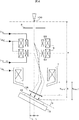
次にチルト像観察および立体像観察について図2および図3を用いて述べる。図2はチルト像観察時の電子線軌道を説明するための図であり、図3は立体像観察時の電子線軌道を説明するための図である。
走査コイル9上段の同位置には、チルト(傾斜)角制御用偏向器53が配置され、チルト像および立体像観察時には、一次電子線4を傾斜させ、対物レンズ7の振り戻し作用を用いて、試料10に一次電子線4をチルトさせて照射する。符号34は傾斜角制御用偏向器制御電源である。
Next, tilt image observation and stereoscopic image observation will be described with reference to FIGS. FIG. 2 is a diagram for explaining an electron beam trajectory during tilt image observation, and FIG. 3 is a diagram for explaining an electron beam trajectory during stereoscopic image observation.
A tilt (tilt)
図2においては、一次電子線4の中心軌道だけでなく、電子線の広がりも示す。フィラメント1から引き出され、第一収束レンズ5および第二収束レンズ6を通った一次電子線4は、光軸上にクロスオーバ100を結び、絞り板8を通り、チルト角制御用偏向器53でもって傾斜される。チルトした電子線61は対物レンズ7の軸外を通り、対物レンズ7の振り戻し作用により、光軸よりチルトして試料10に照射され、チルト像がえられる。
In FIG. 2, not only the center trajectory of the primary electron beam 4 but also the spread of the electron beam is shown. The primary electron beam 4 drawn from the
立体像観察時には、図3に示すように、上記と同様一次電子線4がクロスオーバ100を結び、絞り板8を通過した後、チルト角制御用偏向器53を用いて光軸を対象軸に左右2本のチルトした電子線62、63を形成し、左右のステレオペア画像を取得する。取得した画像は、制御CPU40にて画像処理され、立体視表示モニター(画像表示装置41)などに表示することにより立体像観察が可能になる。
At the time of stereoscopic image observation, as shown in FIG. 3, after the primary electron beam 4 forms a
次に、電子線チルト時の視野ずれの発生メカニズムについて図4を用いて述べる。図4は電子線チルトによる視野ずれ発生のメカニズムの説明図である。ここでは簡単のため、走査のための偏向信号を受けていない、電子線中心軌道にて説明する。 Next, the mechanism of occurrence of visual field shift at the time of electron beam tilt will be described with reference to FIG. FIG. 4 is an explanatory view of the mechanism of occurrence of visual field shift due to electron beam tilt. Here, for the sake of simplicity, the explanation will be made with an electron beam center trajectory that has not received a deflection signal for scanning.
第2集束レンズ6を通過した電子線は、偏向コイル(走査コイル)9およびチルト角制御用偏向器53上方でクロスオーバ100を結ぶ。次に、試料10に角度ωi[rad]にて照射することを目的に、チルト角制御用偏向器53にて角度ω0[rad]にて偏向し、対物レンズ7によって振り戻され試料10に照射される。しかし、電子線到達点は光軸上ではなく、光軸より距離Δriだけずれた点となる。
The electron beam that has passed through the second focusing
これは、チルト角制御用偏向器53により、図4に示すようにチルト電子線のクロスオーバ100が仮想的に光軸より距離Δr0ずれた点となるためである。図4の光学系配置においては幾何学的計算より位置ずれ距離Δriは以下のように求められる。
This is because the tilt
![]()
![]()
ここでMobj、Δr0は以下のようである。 Here, M obj and Δr 0 are as follows.

位置ずれ距離Δriはa、b、ωi、特にωiによって変化し、10°以下のωiでも、数10μm発生する。数百倍の観察でも無視できない物である。なお、aはクロスオーバから対物レンズまでの距離、bは対物レンズから観察試料表面までの距離、D1はチルト角制御用偏向器53から視野補正用アライナー54までの距離を示す。
The misalignment distance Δr i varies depending on a, b, ω i , particularly ω i , and several tens of μm are generated even at ω i of 10 ° or less. Even a few hundred times of observation is not negligible. Here, a is the distance from the crossover to the objective lens, b is the distance from the objective lens to the observation sample surface, and D1 is the distance from the tilt
次に、図5を用いて視野ずれの補正方法について説明する。図5は、上記電子線チルトによる視野ずれの補正方法を説明するための図である。視野ずれの補正は視野補正用アライナー54を用いて行う。具体的には、チルト角制御用偏向器53によって、角度ω0だけ偏向されたチルト電子線を補正角度Δω0[rad]だけ偏向し、仮想的に光軸から距離Δr0だけずれていたクロスオーバを、光軸と一致するように補正する。符号35は視野補正用アライナー制御電源である。なお、仮想的なクロスオーバの光軸からの位置ずれに関し、距離Δr0が±200μm以内であれば光軸と一致していると見なすことができる。
Next, a correction method for visual field deviation will be described with reference to FIG. FIG. 5 is a diagram for explaining a method of correcting the field deviation due to the electron beam tilt. The correction of the visual field deviation is performed by using the visual
図5の光学系配置においては、幾何学的計算より補正角度Δω0は以下のように求められる。 In the optical system arrangement of FIG. 5, the correction angle Δω 0 is obtained as follows from geometric calculation.
上式に基づき、視野補正用アライナー54を用いてチルト電子線観察時の視野ずれを抑制することが可能である。現実的には、視野補正用アライナー54に与える信号は、アライナーが電磁コイルであれば電流となるため、補正角度に応じた電流を与えることになる。
Based on the above equation, it is possible to suppress a field shift during tilt electron beam observation using the
なお、(3)式より補正角度Δω0は、角度ωi、距離aをある観察条件に決定しても、距離bによって変化する(距離D1、D2は装置固有の寸法定数)。 Note that the correction angle Δω 0 from the equation (3) varies depending on the distance b even if the angle ω i and the distance a are determined as a certain observation condition (the distances D1 and D2 are dimensional constants unique to the apparatus).
視野補正用アライナーを備えた荷電粒子線装置を用いて荷電粒子線を対物レンズ上方でチルトさせ、仮想的に光軸からずれるクロスオーバを光軸と一致するように補正して試料観察を行った結果、1000倍以上の高倍率でも所望の位置のチルト像を観察視野内で観察することができた。 Using a charged particle beam device equipped with an aligner for visual field correction, the charged particle beam was tilted above the objective lens, and the sample was observed by correcting the crossover virtually deviating from the optical axis to coincide with the optical axis. As a result, a tilt image at a desired position could be observed in the observation field even at a high magnification of 1000 times or more.
また、上記荷電粒子線装置を用いて細胞や金属結晶、粉体の立体視観察を行った結果、左右の観察位置がずれることなく、良好な立体画像を得ることができた。 In addition, as a result of stereoscopic observation of cells, metal crystals, and powder using the charged particle beam apparatus, a favorable stereoscopic image could be obtained without shifting the left and right observation positions.
以上述べた通り、本実施例によれば、視野補正用アライナーを備えることにより、一次電子線をチルトさせて試料観察する場合であっても、視野ずれの補正を容易に行なうことのできる荷電粒子線装置を提供することができる。また、光軸を対象軸に左右2本のチルトした荷電粒子線を用いて左右のステレオペア画像を取得する場合であっても、視野ずれが抑制され、良好な立体画像が得られる荷電粒子線装置を提供することができる。 As described above, according to the present embodiment, the charged particle can be easily corrected even when the specimen is observed by tilting the primary electron beam by providing the aligner for visual field correction. A wire device can be provided. Further, even when a left and right stereo pair image is acquired using two left and right tilted charged particle beams with the optical axis as a target axis, a charged particle beam that suppresses a visual field shift and obtains a good stereoscopic image. An apparatus can be provided.
第2の実施例について図6〜図10を用いて説明する。なお、実施例1に記載され、本実施例に未記載の事項は特段の事情がない限り本実施例にも適用することができる。図6は本実施例に係る荷電粒子線装置(走査電子顕微鏡)を用いて表面傾斜試料のチルトビーム観察時の荷電粒子線軌道を説明するための図であり、図7は焦点、視野ずれ同時補正時の信号タイムチャートである。 A second embodiment will be described with reference to FIGS. Note that the items described in the first embodiment and not described in the present embodiment can be applied to the present embodiment unless there are special circumstances. FIG. 6 is a diagram for explaining a charged particle beam trajectory at the time of tilt beam observation of a surface tilt sample using the charged particle beam apparatus (scanning electron microscope) according to the present embodiment, and FIG. It is a signal time chart at the time of correction.
図6のように、試料ステージ15の傾斜軸移動などを使用した、大幅な試料表面傾斜θが見られる試料10に対して、試料表面傾斜θにあわせてフォーカスを連続的に変化させる傾斜焦点補正を使用した場合、同時に視野補正用アライナー54による視野ずれも連続的に補正する必要がある。試料ステージ15は、水平面(光軸に対して垂直な面)に対して−20度〜90度の角度で傾けることが可能である。なお、符号105は一次電子線のスキャン方向を示す。また、bmin1は一次電子を走査した際の観察視野内における対物レンズと試料表面との最小距離、bmax1は最大距離を示す。
As shown in FIG. 6, tilt focus correction for continuously changing the focus in accordance with the sample surface tilt θ is performed on the
このときの各種信号制御図が図7である。図中、IDEFは一次電子線を走査するために走査コイル制御電源24から走査コイル9へ供給される偏向信号、Iobjは一次電子線を試料表面に収束させるために対物レンズ制御電源から対物レンズへ供給される対物レンズ信号、ITilt_ALは仮想的なクロスオーバの光軸からの位置ずれを補正するために視野補正用アライナー制御電源から視野補正用アライナーに供給される視野補正用アライナー制御信号を示し、ITiltは傾斜角制御用偏向器信号を示す。上段の偏向信号IDEFにあわせて観察すべき試料の高さ位置が変化するため、中段の対物レンズ信号Iobjを傾斜焦点補正で変化させる。さらに焦点補正に連動して仮想的なクロスオーバ位置が変化するため視野補正用アライナー制御信号ITilt_ALも変化させる。図7においては、偏向信号IDEFが進む(一次電子線が図面右方向へスキャン105される)につれて、試料は下がっているため、対物レンズの性質として、対物レンズ電流Iobjを小さくする(対物レンズフォーカス特性は非線形であり、図7のような傾向をもつ)。それに連動して、視野補正用アライナーの信号ITilt_ALは、bが大きくなるため(bmin1→bmax1)、(3)式に従い徐々に大きくなっていく。これらは制御CPUを用いて行なう。
FIG. 7 shows various signal control diagrams at this time. In the figure, I DEF is a deflection signal supplied from the scanning coil
ただし、この場合、試料傾斜に合わせて偏向信号IDEFは変化させていないので、傾斜した試料が走査幅される範囲は、試料傾斜を行わない場合の走査範囲(±L)と比べて異なり、見かけ上倍率も異なったものとなる。 However, in this case, since the deflection signal I DEF is not changed in accordance with the sample tilt, the range in which the tilted sample is scanned is different from the scan range (± L) when the sample tilt is not performed. Apparently the magnification is also different.
視野補正用アライナー54による視野ずれ補正は、傾斜焦点補正だけでなく、傾斜倍率補正を同時使用することにより、さらに使い勝手のよいものとなる。傾斜倍率補正は、画像の倍率を試料傾斜の前後で変化しないようにする技術であり、走査コイル9の走査範囲を試料傾斜角度に合わせて変更することにより行われる。傾斜倍率補正のための走査範囲の変更は制御CPUを用いて行なう。
The visual field deviation correction by the visual
これらの機能をくみあわせることにより、傾斜試料のチルト像、立体像観察において、焦点をあわせながら、走査範囲および倍率を維持し、そして視野ずれなく観察を行うことが可能である。 By combining these functions, it is possible to maintain the scanning range and magnification while maintaining the focus while observing the tilted image and stereoscopic image of the tilted sample, and perform observation without visual field deviation.
そこで、次に傾斜焦点補正を行う際に、視野ずれ補正だけでなく、傾斜倍率補正を行う方法について図8、図9を用いて説明する。図8は傾斜倍率補正を行いながら傾斜試料のチルトビーム観察を行う際の荷電粒子線軌道を説明するための図であり、図9は焦点、視野ずれ、倍率同時補正時の信号タイムチャートである。なお、図9において、実線が倍率補正を行う場合、破線は倍率補正を行なわない場合を示す。 Therefore, a method of performing tilt magnification correction as well as visual field shift correction when tilt focus correction is performed next will be described with reference to FIGS. FIG. 8 is a diagram for explaining a charged particle beam trajectory when tilt beam observation of a tilted sample is performed while tilt magnification correction is performed, and FIG. 9 is a signal time chart at the time of simultaneous correction of focus, field shift, and magnification. . In FIG. 9, a solid line indicates a case where magnification correction is performed, and a broken line indicates a case where magnification correction is not performed.
傾斜倍率補正機能を用いて傾斜角度θにて傾斜した試料面上を、偏向信号IDEFを制御し、傾斜前と等しい走査範囲±Lにて走査を行う。その際の制御信号の変化を見ると、試料中心高さ(b)を基準とし、光軸左側では偏向幅を増加し、右側では減少させることになる。しかし、走査幅の変化量の左右での差は2%未満と小さく、実際には左右共に傾斜倍率機能を使用前の走査幅Lに傾斜角度θの余弦cosθを乗じたLcosθと変更して差し支えない。それと同時に焦点補正、視野ずれ補正信号も修正する。 The deflection signal I DEF is controlled on the sample surface tilted at the tilt angle θ using the tilt magnification correction function, and scanning is performed in the same scanning range ± L as before tilting. Looking at the change in the control signal at that time, the deflection width is increased on the left side of the optical axis and decreased on the right side with reference to the sample center height (b). However, the difference in the amount of change in the scan width between the left and right is as small as less than 2%. In practice, the tilt magnification function can be changed to Lcosθ obtained by multiplying the scan width L before use by the cosine cosθ of the tilt angle θ. Absent. At the same time, the focus correction and visual field deviation correction signals are also corrected.
次に、本実施例に係る荷電粒子線装置の位置ずれ補正に関するGUI画面について図10を用いて説明する。図10は、本実施例に係る走査電子顕微鏡におけるユーザー入力画面の一例を示す。図より、ユーザーは、視野ずれ補正である“ビームチルト視野補正”と“傾斜焦点補正”、“傾斜倍率補正”の3つの機能について、チェックボックス107をチェックすることによって使用可能である。これらの機能は、個別でも、複数の組合せての使用も可能である。“傾斜焦点補正”、“傾斜倍率補正”にはスライダ109が付き、試料の傾斜角度をユーザーが決定する。
Next, a GUI screen related to positional deviation correction of the charged particle beam apparatus according to the present embodiment will be described with reference to FIG. FIG. 10 shows an example of a user input screen in the scanning electron microscope according to the present embodiment. From the figure, the user can use the three functions of “beam tilt visual field correction”, “tilt focus correction”, and “tilt magnification correction”, which are visual field deviation corrections, by checking the
本実施例に係る荷電粒子線装置を用いて半導体素子を傾斜させ、傾斜焦点補正を行いながらチルト像を観察するに際し、傾斜焦点補正に合わせて、仮想的に光軸からずれるクロスオーバを光軸と一致するように位置ずれ補正しながら試料観察を行った結果、所定位置における良好な斜視画像を得ることができた。更に、上記傾斜焦点補正に合わせて、位置ずれ補正と倍率補正とを行なった結果、より寸法精度の高い画像を得ることができた。 When observing a tilt image while tilting the semiconductor element by tilting the semiconductor element using the charged particle beam apparatus according to the present embodiment and performing tilt focus correction, a crossover that is virtually deviated from the optical axis is adjusted in accordance with the tilt focus correction. As a result of observing the sample while correcting the positional deviation so as to coincide with, a good perspective image at a predetermined position could be obtained. Furthermore, as a result of performing positional deviation correction and magnification correction in accordance with the tilt focus correction, an image with higher dimensional accuracy could be obtained.
以上、本実施例によれば、視野補正用アライナーを備えることにより、傾斜焦点補正を行うような傾斜試料であっても位置ずれが抑制されるため所定位置の観察が可能な荷電粒子線装置を提供することができる。更に、傾斜焦点補正機能を備えることにより、寸法精度の高い斜視画像を得ることができる。 As described above, according to the present embodiment, a charged particle beam apparatus capable of observing a predetermined position is provided by providing a field correction aligner, so that even a tilted sample that performs tilted focus correction suppresses displacement. Can be provided. Furthermore, a perspective image with high dimensional accuracy can be obtained by providing the tilt focus correction function.
なお、本発明は上記した実施例に限定されるものではなく、様々な変形例が含まれる。例えば、上記した実施例は本発明を分かりやすく説明するために詳細に説明したものであり、必ずしも説明した全ての構成を備えるものに限定されるものではない。また、ある実施例の構成の一部を他の実施例の構成に置き換えることも可能であり、また、ある実施例の構成に他の実施例の構成を加えることも可能である。また、各実施例の構成の一部について、他の構成の追加・削除・置換をすることが可能である。 In addition, this invention is not limited to an above-described Example, Various modifications are included. For example, the above-described embodiments have been described in detail for easy understanding of the present invention, and are not necessarily limited to those having all the configurations described. Also, a part of the configuration of a certain embodiment can be replaced with the configuration of another embodiment, and the configuration of another embodiment can be added to the configuration of a certain embodiment. Further, it is possible to add, delete, and replace other configurations for a part of the configuration of each embodiment.
1…フィラメント(陰極)、2…ウェネルト、3…陽極、4…一次電子線、5…第一収束レンズ、6…第二収束レンズ、7…対物レンズ、8…絞り板、9…走査コイル、10…試料、12…二次信号、13…二次信号用検出器、14…信号増幅器、15…試料ステージ、16…ステージ駆動ユニットおよび電源、20…高圧制御電源、21…第一収束レンズ制御電源、22…第二収束レンズ制御電源、23…対物レンズ制御電源、24…走査コイル制御電源、32…非点補正器用制御電源、33…非点補正器用アライナー制御電源、34…傾斜角制御用偏向器制御電源、35…視野補正用アライナー制御電源、40…制御CPU、41…表示モニター、51…非点補正器、52…非点補正器用アライナー、53…傾斜(チルト)角制御用偏向器、54…視野補正用アライナー、61…チルト電子線、62…左側チルト電子線、63…右側チルト電子線、100…クロスオーバ、105…スキャン方向、107…チェックボックス、109…スライダ。
DESCRIPTION OF
Claims (8)
前記対物レンズと前記偏向器の間にアライナーが更に備えられ、
前記アライナーは、前記偏向器のチルト角、前記複数のレンズ条件、前記対物レンズと前記試料までの距離を用いて、前記一次荷電粒子線のチルト時に発生する前記試料の視野ずれを補正するビームチルト視野補正機能を有し、
前記試料の表面傾斜に対応して、前記一次荷電粒子線が前記試料上を1ライン走査中に前記対物レンズの焦点とチルトした前記一次荷電粒子線による視野ずれを同時、連続的に補正する傾斜焦点補正機能を有することを特徴とする荷電粒子線装置。 A charged particle source, a plurality of lenses for converging a primary charged particle beam emitted from the charged particle source, a scanning coil for scanning the primary charged particle beam on a sample, and the sample for converging the primary charged particle An objective lens that irradiates the primary charged particle beam, and a deflector that is arranged above the objective lens and tilts the primary charged particle beam. In the charged particle beam apparatus that obtains a tilt image of the sample or a left-right parallax angle image by irradiating the sample,
An aligner is further provided between the objective lens and the deflector,
The aligner uses a tilt angle of the deflector, the plurality of lens conditions, and a distance between the objective lens and the sample to correct a beam tilt of the sample that occurs when the primary charged particle beam is tilted. have a field of vision correction function,
Corresponding to the surface tilt of the sample, the primary charged particle beam simultaneously and continuously corrects the visual field shift caused by the primary charged particle beam tilted with the focus of the objective lens during one line scanning on the sample. the charged particle beam apparatus characterized in that it have a focus correction function.
前記対物レンズの焦点補正とチルトした前記一次荷電粒子線による視野ずれ補正と同時に走査幅を変更し、前記試料表面傾斜を行わない場合と同等の領域を走査する傾斜倍率補正機能を有することを特徴とする荷電粒子線装置。 The charged particle beam apparatus according to claim 1,
It has a tilt magnification correction function for changing the scanning width at the same time as the focus correction of the objective lens and the visual field shift correction by the tilted primary charged particle beam, and scanning the same area as when the sample surface is not tilted. A charged particle beam device.
更に、画像表示装置を備え、
前記画像表示装置は、ビームチルト視野補正、傾斜焦点補正、傾斜倍率補正の3つの内の少なくとも一つを実行可能とする入力手段を含むGUI画面を表示するものであることを特徴とする荷電粒子線装置。 The charged particle beam apparatus according to claim 2,
Furthermore, an image display device is provided,
The image display apparatus, the beam tilt field correction, slope focus correction, characterized in der Rukoto which displays a GUI screen including an input means enabling the execution of at least one of the three gradient magnification correction charged Particle beam device.
前記対物レンズと前記偏向器の間に視野補正用アライナーが更に備えられ、
前記視野補正用アライナーは、前記偏向器により前記一次荷電粒子線をチルトすることにより前記クロスオーバとは異なる位置に形成される仮想的なクロスオーバの前記光軸からの位置ずれを前記光軸と一致するように前記一次荷電粒子線のチルト角度を補正し、表面傾斜試料にかかる前記左右のステレオペア画像の視野を一致させることを特徴とする荷電粒子線装置。 A charged particle source; a sample stage; a plurality of lenses that converge a primary charged particle beam emitted from the charged particle source to form a crossover on an optical axis; and the sample stage that converges the primary charged particle An objective lens for irradiating a sample placed on the objective lens, and a deflector that is disposed between the objective lens and the crossover and tilts the primary charged particle beam, and deflects the primary charged particle beam. in the tilt to the two primary charged particle beam, the charged particle beam device get a stereo pair images of the left and right of the sample in the lateral axis of symmetry of the optical axis by a vessel,
A field correction aligner is further provided between the objective lens and the deflector,
The visual field aligner aligns a position shift from the optical axis of a virtual crossover formed at a position different from the crossover by tilting the primary charged particle beam by the deflector. match the tilt angle of the primary charged particle beam is corrected so that the charged particle beam apparatus according to claim Rukoto match the field of view of left and right stereo pair images according to surface tilt the specimen.
前記一致は、±200μm以内の範囲を許容することを特徴とする荷電粒子線装置。 The charged particle beam device according to claim 4 .
The match, a charged particle beam apparatus characterized that you permit range within ± 200 [mu] m.
前記チルト角度の補正角度は、前記偏向器によりチルトされる前記一次荷電粒子線のチルト角度と、前記偏向器と前記視野補正用アライナーとの間の距離と、前記視野補正用アライナーと前記対物レンズとの間の距離と、前記複数のレンズにより形成される前記一次荷電粒子線のクロスオーバと前記対物レンズとの間の距離とを用いて決定されることを特徴とする荷電粒子線装置。 The charged particle beam device according to claim 4 .
The tilt angle correction angle includes a tilt angle of the primary charged particle beam tilted by the deflector, a distance between the deflector and the field correction aligner, the field correction aligner, and the objective lens. distance and, a charged particle beam apparatus according to claim Rukoto be determined using the distance between said plurality of said formed by the lens and crossover of the primary charged particle beam the objective lens between.
前記対物レンズと前記偏向器の間に視野補正用アライナーが更に備えられ、
前記傾斜機構を用いて傾斜させた前記試料ステージに載置される前記試料の表面に前記一次荷電粒子線を照射してチルト像を観察する際に、
前記制御CPUは、
前記走査コイルが、傾いた前記試料ステージの傾斜方向に前記一次荷電粒子線を走査するように、かつ、
前記対物レンズが、走査される前記一次荷電粒子線が前記試料の表面において焦点を結ぶように、かつ、
前記視野補正用アライナーが、前記偏向器により前記一次荷電粒子線をチルトすること及び前記対物レンズにより前記一次荷電粒子線の焦点位置を変更することにより前記クロスオーバとは異なる位置に形成される仮想的なクロスオーバの前記光軸からの位置ずれを前記光軸と一致させ前記一次荷電粒子線のチルト角度を補正するように制御するものであることを特徴とする荷電粒子線装置。 A charged particle source, a sample stage, a tilt mechanism that tilts the stage, a plurality of lenses that converge a primary charged particle beam emitted from the charged particle source to form a crossover on an optical axis, and the primary A scanning coil that scans a charged particle beam on a sample placed on the sample stage, an objective lens that converges the primary charged particles and irradiates the sample, and is disposed between the objective lens and the crossover A charged particle beam apparatus comprising: a deflector that tilts the primary charged particle beam; a control CPU that controls the deflector; and an image display device connected to the control CPU .
A field correction aligner is further provided between the objective lens and the deflector,
When observing a tilt image by irradiating the surface of the sample placed on the sample stage tilted using the tilt mechanism with the primary charged particle beam,
The control CPU is
The scanning coil scans the primary charged particle beam in the tilt direction of the tilted sample stage; and
The objective lens so that the primary charged particle beam to be scanned is focused on the surface of the sample; and
The visual field aligner is formed in a position different from the crossover by tilting the primary charged particle beam by the deflector and changing the focal position of the primary charged particle beam by the objective lens. specific crossover of a charged particle beam apparatus according to claim der Rukoto controls to correct the tilt angle of the primary charged particle beam positional deviation is matched with the optical axis from the optical axis.
前記制御CPUは、更に、
前記傾斜前と等しい走査範囲にて走査を行うように前記走査コイルを制御するものであることを特徴とする荷電粒子線装置。 The charged particle beam device according to claim 7 ,
The control CPU further includes:
The charged particle beam apparatus characterized by at inclined front equal scanning range is shall be controlling the scanning coil to perform the scan.
Priority Applications (6)
| Application Number | Priority Date | Filing Date | Title |
|---|---|---|---|
| JP2011012435A JP5364112B2 (en) | 2011-01-25 | 2011-01-25 | Charged particle beam equipment |
| US13/979,964 US9287083B2 (en) | 2011-01-25 | 2011-12-16 | Charged particle beam device |
| CN201180065868.4A CN103348437B (en) | 2011-01-25 | 2011-12-16 | charged particle beam device |
| DE112011104595.6T DE112011104595B4 (en) | 2011-01-25 | 2011-12-16 | Charged particle beam device and method of control |
| KR1020137018107A KR101470270B1 (en) | 2011-01-25 | 2011-12-16 | Charged particle beam device |
| PCT/JP2011/079166 WO2012101927A1 (en) | 2011-01-25 | 2011-12-16 | Charged particle beam device |
Applications Claiming Priority (1)
| Application Number | Priority Date | Filing Date | Title |
|---|---|---|---|
| JP2011012435A JP5364112B2 (en) | 2011-01-25 | 2011-01-25 | Charged particle beam equipment |
Publications (2)
| Publication Number | Publication Date |
|---|---|
| JP2012155911A JP2012155911A (en) | 2012-08-16 |
| JP5364112B2 true JP5364112B2 (en) | 2013-12-11 |
Family
ID=46580510
Family Applications (1)
| Application Number | Title | Priority Date | Filing Date |
|---|---|---|---|
| JP2011012435A Expired - Fee Related JP5364112B2 (en) | 2011-01-25 | 2011-01-25 | Charged particle beam equipment |
Country Status (6)
| Country | Link |
|---|---|
| US (1) | US9287083B2 (en) |
| JP (1) | JP5364112B2 (en) |
| KR (1) | KR101470270B1 (en) |
| CN (1) | CN103348437B (en) |
| DE (1) | DE112011104595B4 (en) |
| WO (1) | WO2012101927A1 (en) |
Families Citing this family (11)
| Publication number | Priority date | Publication date | Assignee | Title |
|---|---|---|---|---|
| JP5331780B2 (en) * | 2010-11-30 | 2013-10-30 | 株式会社日立ハイテクノロジーズ | Electron microscope, image reconstruction system for electron microscope, and image reconstruction method for electron microscope |
| JP5698157B2 (en) | 2012-01-06 | 2015-04-08 | 株式会社日立ハイテクノロジーズ | Charged particle beam apparatus and tilt observation image display method |
| JP6022344B2 (en) * | 2012-12-21 | 2016-11-09 | 株式会社日立ハイテクノロジーズ | Arithmetic device and charged particle beam application device |
| JP6165643B2 (en) * | 2014-01-23 | 2017-07-19 | 株式会社日立ハイテクサイエンス | Charged particle beam device, control method of charged particle beam device, and cross-section processing observation device |
| US10593514B2 (en) * | 2015-06-08 | 2020-03-17 | Nikon Corporation | Charged particle beam irradiation apparatus and device manufacturing method |
| DE112016005577B4 (en) | 2016-01-29 | 2021-09-16 | Hitachi High-Tech Corporation | Charge carrier beam device and method for adjusting its optical axis |
| JP6743787B2 (en) * | 2017-09-13 | 2020-08-19 | 株式会社ニューフレアテクノロジー | Charged particle beam drawing apparatus and blanking circuit failure diagnosis method |
| JP6930431B2 (en) * | 2018-01-10 | 2021-09-01 | 株式会社ニューフレアテクノロジー | Aperture alignment method and multi-charged particle beam drawing device |
| JP7047523B2 (en) * | 2018-03-26 | 2022-04-05 | 株式会社島津製作所 | Charged particle beam alignment device, charged particle beam irradiation device and charged particle beam alignment method |
| US10504684B1 (en) * | 2018-07-12 | 2019-12-10 | ICT Integrated Circuit Testing Gesellschaft für Halbleiterprüftechnik mbH | High performance inspection scanning electron microscope device and method of operating the same |
| CN115497793B (en) * | 2022-10-20 | 2023-08-22 | 国仪量子(合肥)技术有限公司 | Scanning electron microscope, control method thereof, control device thereof and storage medium |
Family Cites Families (27)
| Publication number | Priority date | Publication date | Assignee | Title |
|---|---|---|---|---|
| NL7012671A (en) | 1970-08-27 | 1972-02-29 | ||
| JPS60200450A (en) | 1984-03-26 | 1985-10-09 | Hitachi Ltd | scanning electron microscope |
| US5338839A (en) | 1988-04-12 | 1994-08-16 | Massachusetts Institute Of Technology | DNA encoding nestin protein |
| JPH0233843A (en) | 1988-07-25 | 1990-02-05 | Hitachi Ltd | Scanning electronic microscope |
| JP2509075Y2 (en) * | 1988-09-26 | 1996-08-28 | 北川工業株式会社 | Noise current absorber |
| US5338939A (en) * | 1992-01-13 | 1994-08-16 | Fujitsu Limited | Charged particle beam exposure including a heat blocking partition positioned near deflecting coils |
| JPH05258700A (en) * | 1992-03-13 | 1993-10-08 | Jeol Ltd | Scanning image observing method and scanning electron microscope |
| US5414261A (en) * | 1993-07-01 | 1995-05-09 | The Regents Of The University Of California | Enhanced imaging mode for transmission electron microscopy |
| JP3654022B2 (en) | 1998-12-25 | 2005-06-02 | 株式会社日立製作所 | Charged particle beam equipment |
| JP2001273861A (en) * | 2000-03-28 | 2001-10-05 | Toshiba Corp | Charged beam device and pattern tilt observation method |
| JP2002343293A (en) | 2001-05-17 | 2002-11-29 | Hitachi Ltd | Scanning electron microscope equipment |
| JP2003100246A (en) * | 2001-09-25 | 2003-04-04 | Toshiba Corp | Charged beam device, pattern measuring method and pattern drawing method |
| JP4094042B2 (en) | 2002-09-11 | 2008-06-04 | 株式会社日立ハイテクノロジーズ | Charged particle beam apparatus and charged particle beam irradiation method |
| JP3968334B2 (en) * | 2002-09-11 | 2007-08-29 | 株式会社日立ハイテクノロジーズ | Charged particle beam apparatus and charged particle beam irradiation method |
| US7067808B2 (en) * | 2003-10-14 | 2006-06-27 | Topcon Corporation | Electron beam system and electron beam measuring and observing method |
| JP4229799B2 (en) | 2003-10-14 | 2009-02-25 | 株式会社トプコン | Electron beam measurement or observation device, electron beam measurement or observation method |
| JP4383950B2 (en) | 2004-04-23 | 2009-12-16 | 株式会社日立ハイテクノロジーズ | Charged particle beam adjustment method and charged particle beam apparatus |
| US7075093B2 (en) * | 2004-05-12 | 2006-07-11 | Gorski Richard M | Parallel multi-electron beam lithography for IC fabrication with precise X-Y translation |
| JP4620981B2 (en) * | 2004-08-10 | 2011-01-26 | 株式会社日立ハイテクノロジーズ | Charged particle beam equipment |
| JP4857101B2 (en) * | 2006-12-21 | 2012-01-18 | 株式会社日立ハイテクノロジーズ | Probe evaluation method |
| CZ298798B6 (en) | 2007-07-30 | 2008-01-30 | Tescan, S. R. O. | Device for spatial real time representation of a sample |
| JP5028297B2 (en) * | 2008-02-22 | 2012-09-19 | 株式会社日立ハイテクノロジーズ | Charged particle beam device with aberration corrector |
| JP2009205904A (en) * | 2008-02-27 | 2009-09-10 | Hitachi High-Technologies Corp | Cold cathode type field emission electron gun and electron beam device using the same |
| JP5183318B2 (en) * | 2008-06-26 | 2013-04-17 | 株式会社日立ハイテクノロジーズ | Charged particle beam equipment |
| JP4431624B2 (en) | 2008-08-25 | 2010-03-17 | 株式会社日立ハイテクノロジーズ | Charged particle beam adjustment method and charged particle beam apparatus |
| JP2010016007A (en) | 2009-10-22 | 2010-01-21 | Hitachi High-Technologies Corp | Charged particle beam adjustment method, and charged particle beam device |
| DE102009052392A1 (en) * | 2009-11-09 | 2011-12-15 | Carl Zeiss Nts Gmbh | SACP process and particle-optical system for carrying out such a process |
-
2011
- 2011-01-25 JP JP2011012435A patent/JP5364112B2/en not_active Expired - Fee Related
- 2011-12-16 CN CN201180065868.4A patent/CN103348437B/en not_active Expired - Fee Related
- 2011-12-16 US US13/979,964 patent/US9287083B2/en not_active Expired - Fee Related
- 2011-12-16 WO PCT/JP2011/079166 patent/WO2012101927A1/en not_active Ceased
- 2011-12-16 KR KR1020137018107A patent/KR101470270B1/en not_active Expired - Fee Related
- 2011-12-16 DE DE112011104595.6T patent/DE112011104595B4/en not_active Expired - Fee Related
Also Published As
| Publication number | Publication date |
|---|---|
| DE112011104595T5 (en) | 2014-01-16 |
| CN103348437B (en) | 2014-10-29 |
| CN103348437A (en) | 2013-10-09 |
| US20130299715A1 (en) | 2013-11-14 |
| KR20130112921A (en) | 2013-10-14 |
| KR101470270B1 (en) | 2014-12-05 |
| DE112011104595B4 (en) | 2015-10-01 |
| JP2012155911A (en) | 2012-08-16 |
| US9287083B2 (en) | 2016-03-15 |
| WO2012101927A1 (en) | 2012-08-02 |
Similar Documents
| Publication | Publication Date | Title |
|---|---|---|
| JP5364112B2 (en) | Charged particle beam equipment | |
| JP4383950B2 (en) | Charged particle beam adjustment method and charged particle beam apparatus | |
| JP5792509B2 (en) | Charged particle beam apparatus and sample processing method | |
| US9012842B2 (en) | Charged particle beam device and inclined observation image display method | |
| US8143573B2 (en) | Charged particle beam apparatus | |
| JP6620170B2 (en) | Charged particle beam apparatus and optical axis adjustment method thereof | |
| JP6647854B2 (en) | Aberration correction method and charged particle beam device | |
| JP2006012664A (en) | Charged particle beam apparatus and optical axis adjustment method thereof | |
| JP2011054426A (en) | Charged particle beam irradiation device and axis alignment adjustment method of the device | |
| JP2003168383A (en) | Scanning electron microscope equipment | |
| US12261013B2 (en) | Charged particle beam system and control method therefor | |
| KR102628711B1 (en) | Charged particle beam device | |
| TW202036636A (en) | Charged particle beam device | |
| WO2021100172A1 (en) | Charged particle beam device and aberration correction method | |
| TWI748527B (en) | Charged particle beam device | |
| JP4431624B2 (en) | Charged particle beam adjustment method and charged particle beam apparatus | |
| JP6959969B2 (en) | Charged particle beam device | |
| JP2004146192A (en) | Sample observation method by transmission electron microscope | |
| JP2010016007A (en) | Charged particle beam adjustment method, and charged particle beam device | |
| JP2011238635A (en) | Scanning charged corpuscular beam device | |
| JP2009135119A (en) | Optical axis adjustment method for charged particle beam apparatus |
Legal Events
| Date | Code | Title | Description |
|---|---|---|---|
| A621 | Written request for application examination |
Free format text: JAPANESE INTERMEDIATE CODE: A621 Effective date: 20130215 |
|
| A131 | Notification of reasons for refusal |
Free format text: JAPANESE INTERMEDIATE CODE: A131 Effective date: 20130604 |
|
| A521 | Request for written amendment filed |
Free format text: JAPANESE INTERMEDIATE CODE: A523 Effective date: 20130801 |
|
| TRDD | Decision of grant or rejection written | ||
| A01 | Written decision to grant a patent or to grant a registration (utility model) |
Free format text: JAPANESE INTERMEDIATE CODE: A01 Effective date: 20130827 |
|
| A61 | First payment of annual fees (during grant procedure) |
Free format text: JAPANESE INTERMEDIATE CODE: A61 Effective date: 20130906 |
|
| R150 | Certificate of patent or registration of utility model |
Ref document number: 5364112 Country of ref document: JP Free format text: JAPANESE INTERMEDIATE CODE: R150 Free format text: JAPANESE INTERMEDIATE CODE: R150 |
|
| S531 | Written request for registration of change of domicile |
Free format text: JAPANESE INTERMEDIATE CODE: R313531 |
|
| S533 | Written request for registration of change of name |
Free format text: JAPANESE INTERMEDIATE CODE: R313533 |
|
| R350 | Written notification of registration of transfer |
Free format text: JAPANESE INTERMEDIATE CODE: R350 |
|
| LAPS | Cancellation because of no payment of annual fees |