WO2011007702A1 - Ion-conducting particle and manufacturing method therefor, ion-conducting composite, membrane electrode assembly (mea), and electrochemical device - Google Patents
Ion-conducting particle and manufacturing method therefor, ion-conducting composite, membrane electrode assembly (mea), and electrochemical device Download PDFInfo
- Publication number
- WO2011007702A1 WO2011007702A1 PCT/JP2010/061512 JP2010061512W WO2011007702A1 WO 2011007702 A1 WO2011007702 A1 WO 2011007702A1 JP 2010061512 W JP2010061512 W JP 2010061512W WO 2011007702 A1 WO2011007702 A1 WO 2011007702A1
- Authority
- WO
- WIPO (PCT)
- Prior art keywords
- group
- ion
- fine particles
- fluorine
- ion conductive
- Prior art date
Links
Images


Classifications
-
- H—ELECTRICITY
- H01—ELECTRIC ELEMENTS
- H01B—CABLES; CONDUCTORS; INSULATORS; SELECTION OF MATERIALS FOR THEIR CONDUCTIVE, INSULATING OR DIELECTRIC PROPERTIES
- H01B1/00—Conductors or conductive bodies characterised by the conductive materials; Selection of materials as conductors
- H01B1/06—Conductors or conductive bodies characterised by the conductive materials; Selection of materials as conductors mainly consisting of other non-metallic substances
- H01B1/12—Conductors or conductive bodies characterised by the conductive materials; Selection of materials as conductors mainly consisting of other non-metallic substances organic substances
- H01B1/122—Ionic conductors
-
- H—ELECTRICITY
- H01—ELECTRIC ELEMENTS
- H01M—PROCESSES OR MEANS, e.g. BATTERIES, FOR THE DIRECT CONVERSION OF CHEMICAL ENERGY INTO ELECTRICAL ENERGY
- H01M8/00—Fuel cells; Manufacture thereof
- H01M8/10—Fuel cells with solid electrolytes
- H01M8/1016—Fuel cells with solid electrolytes characterised by the electrolyte material
- H01M8/1018—Polymeric electrolyte materials
- H01M8/1041—Polymer electrolyte composites, mixtures or blends
- H01M8/1046—Mixtures of at least one polymer and at least one additive
- H01M8/1048—Ion-conducting additives, e.g. ion-conducting particles, heteropolyacids, metal phosphate or polybenzimidazole with phosphoric acid
-
- H—ELECTRICITY
- H01—ELECTRIC ELEMENTS
- H01M—PROCESSES OR MEANS, e.g. BATTERIES, FOR THE DIRECT CONVERSION OF CHEMICAL ENERGY INTO ELECTRICAL ENERGY
- H01M8/00—Fuel cells; Manufacture thereof
- H01M8/10—Fuel cells with solid electrolytes
- H01M8/1009—Fuel cells with solid electrolytes with one of the reactants being liquid, solid or liquid-charged
- H01M8/1011—Direct alcohol fuel cells [DAFC], e.g. direct methanol fuel cells [DMFC]
-
- H—ELECTRICITY
- H01—ELECTRIC ELEMENTS
- H01M—PROCESSES OR MEANS, e.g. BATTERIES, FOR THE DIRECT CONVERSION OF CHEMICAL ENERGY INTO ELECTRICAL ENERGY
- H01M8/00—Fuel cells; Manufacture thereof
- H01M8/10—Fuel cells with solid electrolytes
- H01M8/1016—Fuel cells with solid electrolytes characterised by the electrolyte material
- H01M8/1018—Polymeric electrolyte materials
- H01M8/1069—Polymeric electrolyte materials characterised by the manufacturing processes
- H01M8/1081—Polymeric electrolyte materials characterised by the manufacturing processes starting from solutions, dispersions or slurries exclusively of polymers
-
- Y—GENERAL TAGGING OF NEW TECHNOLOGICAL DEVELOPMENTS; GENERAL TAGGING OF CROSS-SECTIONAL TECHNOLOGIES SPANNING OVER SEVERAL SECTIONS OF THE IPC; TECHNICAL SUBJECTS COVERED BY FORMER USPC CROSS-REFERENCE ART COLLECTIONS [XRACs] AND DIGESTS
- Y02—TECHNOLOGIES OR APPLICATIONS FOR MITIGATION OR ADAPTATION AGAINST CLIMATE CHANGE
- Y02E—REDUCTION OF GREENHOUSE GAS [GHG] EMISSIONS, RELATED TO ENERGY GENERATION, TRANSMISSION OR DISTRIBUTION
- Y02E60/00—Enabling technologies; Technologies with a potential or indirect contribution to GHG emissions mitigation
- Y02E60/30—Hydrogen technology
- Y02E60/50—Fuel cells
-
- Y—GENERAL TAGGING OF NEW TECHNOLOGICAL DEVELOPMENTS; GENERAL TAGGING OF CROSS-SECTIONAL TECHNOLOGIES SPANNING OVER SEVERAL SECTIONS OF THE IPC; TECHNICAL SUBJECTS COVERED BY FORMER USPC CROSS-REFERENCE ART COLLECTIONS [XRACs] AND DIGESTS
- Y02—TECHNOLOGIES OR APPLICATIONS FOR MITIGATION OR ADAPTATION AGAINST CLIMATE CHANGE
- Y02P—CLIMATE CHANGE MITIGATION TECHNOLOGIES IN THE PRODUCTION OR PROCESSING OF GOODS
- Y02P70/00—Climate change mitigation technologies in the production process for final industrial or consumer products
- Y02P70/50—Manufacturing or production processes characterised by the final manufactured product
Definitions
- the present invention relates to an ion conductive fine particle having an ion dissociable group and having an affinity for a fluorine-containing resin, a production method thereof, an ion conductive composite containing the ion conductive fine particle, and
- the present invention relates to a membrane electrode assembly (MEA) using an ion conductive composite as an electrolyte, and an electrochemical device such as a fuel cell.
- MEA membrane electrode assembly
- Fuel cells are actively researched and developed as power supply devices because they have high energy conversion efficiency and do not produce environmental pollutants such as nitrogen oxides.
- portable electronic devices such as notebook personal computers and mobile phones have tended to increase power consumption as their functionality and functionality have increased. Power supplies for portable electronic devices that can respond to this trend As a result, expectations for fuel cells are high.
- a fuel cell fuel is supplied to the negative electrode (anode) side to oxidize the fuel, air or oxygen is supplied to the positive electrode (cathode) side to reduce oxygen, and in the entire fuel cell, the fuel is oxidized by oxygen.
- the fuel cell has a feature that it can continue to be used as a power source by replenishing fuel unless it fails.
- Fuel cells are classified into alkaline electrolyte fuel cells, phosphoric acid fuel cells, molten carbonate fuel cells, solid oxide fuel cells, polymer electrolyte fuel cells (PEFC), etc., depending on the electrolyte used. .
- PEFC polymer electrolyte fuel cells
- PEFC can be operated at a temperature lower than that of other types of fuel cells, for example, about 30 ° C. to 130 ° C., because the electrolyte is not scattered in a solid state, and the startup time is short. Therefore, it is suitable as a portable power source.
- FIG. 8 is a cross-sectional view showing an example of the structure of a fuel cell configured as a PEFC.
- an anode (fuel electrode) 22 and a cathode (oxygen electrode) 23 are bonded to both sides of the hydrogen ion (proton) conductive polymer electrolyte membrane 21 so as to face each other.
- a body (MEA) 24 is formed.
- polymer electrolyte particles having hydrogen ion (proton) conductivity and electron conduction are formed on the surface of a gas permeable current collector (gas diffusion layer) 22 a made of a porous conductive material such as a carbon sheet or carbon cloth.
- the porous anode catalyst layer 22b containing the catalyst particles having the property is formed, and the gas diffusion electrode is formed.
- the cathode 23 has polymer electrolyte particles having hydrogen ion (proton) conductivity on the surface of a gas permeable current collector (gas diffusion layer) 23a made of a porous support such as a carbon sheet.
- a porous cathode catalyst layer 23b containing catalyst particles having electron conductivity is formed, and a gas diffusion electrode is formed.
- the catalyst particles may be particles made of the catalyst material alone, or may be composite particles in which the catalyst material is supported on a carrier.
- the membrane electrode assembly (MEA) 24 is sandwiched between the fuel flow path 31 and the oxygen (air) flow path 34 and incorporated in the fuel cell 20.
- fuel is supplied from the fuel inlet 32 and discharged from the fuel outlet 33 on the anode 22 side.
- part of the fuel passes through the gas permeable current collector (gas diffusion layer) 22a and reaches the anode catalyst layer 22b.
- various combustible substances such as hydrogen and methanol can be used.
- oxygen or air is supplied from an oxygen (air) inlet 35 and discharged from an oxygen (air) outlet 36.
- part of oxygen (air) passes through the gas permeable current collector (gas diffusion layer) 23a and reaches the cathode catalyst layer 23b.
- the hydrogen supplied to the anode catalyst layer 22b is expressed by the following reaction formula (1) on the anode catalyst particles.
- 2H 2 ⁇ 4H + + 4e - ⁇ (1) It is oxidized by the reaction shown in FIG.
- the generated hydrogen ion H + moves through the polymer electrolyte membrane 21 to the cathode 23 side.
- Oxygen supplied to the cathode catalyst layer 23b is expressed by the following reaction formula (2) on the hydrogen ions that have moved from the anode side and on the cathode catalyst particles.
- O 2 + 4H + + 4e ⁇ ⁇ 2H 2 O (2) It is reduced by the reaction shown in FIG.
- the following reaction formula (3) is obtained by combining the formulas (1) and (2).
- 2H 2 + O 2 ⁇ 2H 2 O (3) The reaction indicated by
- Gas fuel such as hydrogen is not suitable for miniaturization because it requires a high-pressure container for storage.
- liquid fuel such as methanol has an advantage that it can be easily stored.
- a fuel cell that extracts hydrogen from liquid fuel by a reformer is not suitable for miniaturization because the structure is complicated.
- a direct methanol fuel cell (DMFC) that is supplied directly to the anode and reacted without reforming methanol is easy to store fuel, has a simple structure, and is easy to downsize.
- DMFCs Conventionally, many DMFCs have been studied as a kind of PEFC in combination with PEFC, and are most expected as a power source for portable electronic devices.
- Nafion registered trademark of DuPont
- Nafion registered trademark
- Nafion is composed of a polymer having a perfluorinated hydrophobic molecular skeleton, a hydrophilic sulfonic acid group, and a perfluorinated side chain.
- hydrogen ions dissociated from a sulfonic acid group diffuse and move using water taken into the polymer matrix as a channel, whereby hydrogen ion conductivity is expressed. Therefore, the Nafion (registered trademark) membrane exhibits excellent hydrogen ion conductivity in a wet state in which moisture is sufficiently absorbed.
- the hydrogen ion conductivity of the Nafion (registered trademark) membrane rapidly decreases.
- water taken into the polymer is held in a phase-separated state from the hydrophobic polymer skeleton, so it is unstable and the water content changes greatly depending on the temperature, and the hydrogen ion conductivity depends on temperature. The nature is great.
- moisture is lost due to evaporation at a high temperature, and water freezes at a low temperature. Therefore, in order to prevent these, the temperature range in which the fuel cell can operate is limited.
- the Nafion (registered trademark) membrane has a low performance for blocking the permeation of methanol, and the DMFC using the Nafion (registered trademark) membrane has a remarkable decrease in power generation performance due to methanol crossover.
- fluorosulfonic acid-based polymers generally have high material costs, resulting in increased costs for electrochemical devices using them, such as fuel cells.
- Patent Document 1 a carbonaceous material derivative in which a proton dissociable group is introduced into a carbonaceous material mainly composed of carbon clusters, particularly carbon clusters having a specific molecular structure such as fullerene, It has been proposed to be used as a material for a hydrogen ion conductive electrolyte membrane.
- the “carbon cluster” is an aggregate formed by bonding a few to several hundred carbon atoms, regardless of the type of carbon-carbon bond, which occupies a large number of carbon atoms.
- the term “proton dissociable group” is meant to mean a functional group that is capable of ionizing and leaving a hydrogen atom as a proton (hydrogen ion H +) from the group.
- “carbon cluster” and “proton dissociable group” are similarly defined.
- a proton dissociable molecule in which a proton dissociable group is introduced into a carbon cluster such as fullerene exhibits hydrogen ion conductivity in an aggregated state. This is considered to be because a large number of proton dissociable groups exist in one fullerene molecule, so that the number of proton dissociable groups contained per unit volume is very large.
- fullerene derivatives such as fullerene polymers in which the fullerenes are connected by an organic group are synthesized, and among them, chemical and thermal stability compared to the fullerene derivatives exemplified in Patent Document 1.
- fullerene derivatives which are described as being suitable as a constituent material of a hydrogen ion conductive electrolyte membrane have been reported (for example, JP 2003-123793 A, JP 2003-187636 A, JP 2003 2003). -303513, JP-A-2004-55562, and JP-A-2005-68124.)
- the performance to be satisfied by the hydrogen ion conductive electrolyte membrane 21 used in the fuel cell 20 and the like is diverse, and not only has high hydrogen ion conductivity, but also has excellent mechanical strength and appropriate flexibility. In addition, sufficient performance to prevent permeation of fuel and oxygen (cross leak), and excellent water resistance, chemical stability, and heat resistance are required.
- fullerene-based hydrogen ion conductive materials are mostly powders, and polymers with excellent film-forming properties such as film-forming properties, mechanical strength and flexibility of membranes, and fuel and oxygen permeation-preventing properties May be inferior to the material.
- Patent Document 1 and Patent Document 2 described later a carbon cluster derivative having a proton-dissociable group is combined with a polymer material having excellent film-forming properties, thereby forming a film-forming property and a film machine.
- a structure for improving the mechanical strength and flexibility, and the permeation preventing performance of fuel and oxygen has been proposed.
- Patent Document 1 exemplifies polyfluoroethylene such as polytetrafluoroethylene (PTFE), polyvinylidene fluoride (PVDF), and polyvinyl alcohol (PVA) as a polymer material excellent in film formability.
- PTFE polytetrafluoroethylene
- PVDF polyvinylidene fluoride
- PVA polyvinyl alcohol
- Patent Document 2 a carbon cluster derivative having a proton dissociable group is mixed with a polymer material that is difficult to permeate liquid molecules such as water and / or alcohol molecules, and the mixing ratio of the polymer material is as follows.
- Proton-conducting composites have been proposed that are more than 15% by weight and 95% by weight or less, more preferably 20% by weight or more and 90% by weight or less.
- the polymer material preferably contains at least a vinylidene fluoride homopolymer or copolymer, and the copolymer is preferably a copolymer with hexafluoropropene.
- Patent Document 2 explains as follows. That is, with the above configuration, while maintaining the high proton conductivity of the carbon cluster derivative, it is excellent in film formability, mechanical strength and chemical stability of the film, and water, methanol, etc. It is possible to realize a proton-conducting composite having excellent performance for blocking the permeation of liquid molecules. At this time, the carbon cluster derivative provides a hydrogen ion transmission path having high proton conductivity. On the other hand, the polymer material has a function of blocking the movement of liquid molecules such as water and methanol and preventing swelling of the carbon cluster derivative by high film forming properties and mechanical strength.
- Patent Document 3 proposes amorphous carbon having a sulfonic acid group introduced as a hydrogen ion conductive material having high proton conductivity, excellent heat resistance, and low production cost.
- This material can be produced by heat treating an organic compound in concentrated sulfuric acid or fuming sulfuric acid. At this time, carbonization, sulfonation, and condensation of rings occur, and sulfonic acid group-introduced amorphous carbon is generated.
- the raw material organic compound aromatic hydrocarbons can be used, but natural products such as saccharides and synthetic polymer compounds may be used, and raw materials that are not purified organic compounds, such as aromatics, may be used. Heavy oil containing hydrocarbons, pitch, tar, asphalt and the like may be used.
- Patent Document 3 discloses homopolymers or copolymers of fluorine-containing monomers such as tetrafluoroethylene, chlorotrifluoroethylene, vinyl fluoride, vinylidene fluoride, hexafluoropropene, and perfluoroalkyl vinyl ether as binder polymers. It is described that the stability of the electrolyte membrane is remarkably improved by using it.
- WO01 / 06519 (Claims 1, 4, 5, 16 and 18, pages 3, 6-11, 13 and 14; FIGS. 1-5 and 7) JP 2005-93417 A (pages 8 and 12-14, FIGS. 1-4, 6 and 7) JP 2006-257234 A (3rd and 5-8 pages, FIG. 1)
- a composite of ion conductive fine particles having an ion dissociable group such as carbon cluster derivatives and amorphous carbon having a sulfonic acid group and a fluorine-containing resin such as PVDF or a copolymer thereof is excellent in performance of blocking the permeation of water, methanol, etc., and if a hydrogen ion conductive electrolyte membrane is produced using this composite, it is suitable as a direct methanol fuel cell (DMFC).
- DMFC direct methanol fuel cell
- the fluorine-containing resin does not have ionic conductivity, in order to increase the ionic conductivity of the composite, it is necessary to increase the content of the ionic conductive fine particles in the composite as much as possible.
- the fluorine-containing resin exhibits a very strong water repellency, and does not have an affinity for the strongly hydrophilic ion dissociative group of the ion conductive fine particles. For this reason, there is an upper limit to the content of ion-conductive fine particles that can be uniformly mixed with the fluorine-containing resin.
- the present invention has been made in order to solve the above-described problems, and an object of the present invention is to provide ion-conductive fine particles having an ion dissociable group and having affinity for a fluorine-containing resin, and To provide a manufacturing method, an ion conductive composite containing the ion conductive fine particles, a membrane electrode assembly (MEA) using the ion conductive composite as an electrolyte, and an electrochemical device such as a fuel cell. is there.
- MEA membrane electrode assembly
- the present invention provides an ion dissociable group on the surface of the substrate fine particles, It binds to the surface of the substrate fine particle only at one end, has no ion dissociable group at the other end, and has affinity for the fluorine-containing resin at the main part and / or the other end.
- the present invention relates to ion-conducting fine particles having a modifying group containing an atomic group.
- the raw material fine particles having an ion dissociable group and a first reactive group on the surface of the substrate fine particles It has a second reactive group that can bind to the first reactive group only at one end, does not have an ion dissociable group at the other end, and has fluorine at the main and / or the other end.
- the reaction molecule containing the atomic group having affinity for the containing resin acts, Due to the reaction between the first reactive group and the second reactive group, it is bonded to the surface of the substrate fine particle only at one end, and has no ion dissociable group at the other end, Alternatively, the present invention relates to a method for producing ion-conductive fine particles, in which a modifying group containing an atomic group having an affinity for a fluorine-containing resin is introduced at the other end.
- the present invention also provides The present invention relates to an ion conductive composite containing ion conductive fine particles and a fluorine-containing resin.
- a membrane electrode assembly in which the ion conductive composite is sandwiched between the counter electrodes as an electrolyte, and the electricity constituting the electrochemical reaction unit, in which the ion conductive composite is sandwiched between the counter electrodes as an electrolyte.
- the ion conductive fine particle of the present invention has a modified group containing an atomic group (group) having an affinity for the fluorine-containing resin in addition to the ion dissociable group on the surface of the substrate fine particle. Affinity and dispersibility for the contained resin are improved.
- the modifying group is bonded to the surface of the base particle only at one end portion and does not have an ion dissociable group at the other end portion, the main portion of the modifying group and / or the other
- the atomic groups (groups) having an affinity for the fluorine-containing resin that occupy the end of each can easily contact the fluorine-containing resin. For this reason, atomic groups (groups) having an affinity for fluorine-containing resins function effectively, and by introducing a relatively small amount of modifying groups, the affinity between ion-conductive fine particles and fluorine-containing resins Can be improved.
- the ion conductive composite composed of the ion conductive fine particles and the fluorine-containing resin
- the upper limit of the content of the ion conductive fine particles that can be uniformly mixed with the fluorine-containing resin is improved.
- the ion conductive composite The density of ion dissociable groups in the body can be increased, and the ionic conductivity of the ion conductive composite can be improved.
- the raw material fine particles having an ion dissociable group and a first reactive group on the surface of the substrate fine particles It has a second reactive group that can bind to the first reactive group only at one end, does not have an ion dissociable group at the other end, and has fluorine at the main and / or the other end.
- the reaction molecule containing the atomic group having affinity for the containing resin acts, Due to the reaction between the first reactive group and the second reactive group, it is bonded to the surface of the substrate fine particle only at one end, and has no ion dissociable group at the other end, Alternatively, since a modifying group containing an atomic group having an affinity for the fluorine-containing resin is introduced at the other end, fine particles that have been conventionally used as ion conductive fine particles can be used as a raw material easily and reliably.
- the ion conductive fine particles of the present invention can be produced.
- the ion conductive composite of the present invention comprises the ion conductive fine particles of the present invention and a fluorine-containing resin
- the upper limit of the content of ion conductive fine particles that can be uniformly mixed with the fluorine-containing resin is improved.
- the content of the ion conductive fine particles in the ion conductive composite and the density of the ion dissociative group can be increased, and the ion conductivity of the ion conductive composite can be improved.
- the membrane electrode assembly (MEA) and the electrochemical device of the present invention have the ion conductive composite of the present invention as an electrolyte, the electrochemical characteristics are improved.
- the atomic group having an affinity for the fluorine-containing resin may be a fluorine-containing organic group.
- the fluorine-containing organic group preferably contains a perfluoroalkyl group.
- the substrate fine particles are carbon clusters, amorphous carbon fine particles, or silica fine particles.
- the ion dissociable groups are proton H + , lithium ion Li + , sodium ion Na + , potassium ion K + , magnesium ion Mg 2+ , calcium ion Ca 2+ , strontium ion Sr 2+ and barium ion Ba 2+ . It is good to include either.
- the ion dissociable group is a hydrogen ion dissociable group and preferably has hydrogen ion conductivity.
- the hydrogen ion dissociable groups are hydroxy group —OH, sulfonic acid group —SO 3 H, carboxy group —COOH, phosphono group —PO (OH) 2 , phosphoric acid dihydrogen ester group —O—PO (OH ) 2 , phosphonomethano group> CH (PO (OH) 2 ), diphosphonomethano group> C (PO (OH) 2 ) 2 , phosphonomethyl group —CH 2 (PO (OH) 2 ), diphosphonomethyl group —CH (PO (OH)) 2 ) It may be one or more groups selected from the group consisting of 2 , phosphine group —PHO (OH), —PO (OH) —, and —O—PO (OH) —.
- the methano group> CH 2 is an atomic group in which the carbon atom of the carbon
- the reaction may be performed by a reaction using a silane coupling agent as a reaction molecule, an esterification reaction of a carboxy group, or a reaction using a chlorosulfonyl compound as a reaction molecule.
- the fluorine-containing resin may be a homopolymer or copolymer of vinylidene fluoride, tetrafluoroethylene, or hexafluoropropene.
- the copolymer of vinylidene fluoride is preferably a copolymer with hexafluoropropene.
- PVDF Polyvinylidene fluoride
- the electrochemical device of the present invention is preferably configured as a fuel cell.
- FIG. 1A is a conceptual diagram showing the surface structure of ion-conductive fine particles 1 having improved affinity for fluorine-containing resin 7 based on Embodiment 1.
- FIG. The ion conductive fine particles 1 are bonded to the surface of the substrate fine particles 2, the ion dissociable group 3 existing on the surface thereof, and the surface of the substrate fine particles 2 only at one end, and the main part and / or the other end. In part, it is constituted by a modifying group 4 containing an atomic group (group) 5 having affinity for the fluorine-containing resin.
- the modifying group 4 does not exist.
- the fluorine-containing resin since the fluorine-containing resin exhibits very strong water repellency, the fluorine-containing resin does not have affinity with the ion-dissociable group 2 having high hydrophilicity that the ion-conductive fine particles have.
- this upper limit is exceeded, the ion conductive fine particles and the fluorine-containing resin are easily phase-separated, and the ion conductive fine particles are not uniformly dispersed in the composite. As a result, the ionic conductivity is lowered, and the fuel cell, etc. When it is applied to, it will cause the characteristics to deteriorate.
- the fluorine-containing resin 7 improves affinity and dispersibility for.
- the modifying group 4 is bonded to the surface of the base particle 2 only at one end, an atomic group (group) 5 occupying the main part and / or the other end of the modifying group 4. However, it can contact the fluorine-containing resin 7 easily.
- the atomic group (group) 5 having an affinity for the fluorine-containing resin 7 functions effectively, and by introducing a relatively small amount of the modifying group 4, the ion conductive fine particles 1 and the fluorine-containing resin are introduced.
- the affinity with 7 can be remarkably improved.
- the upper limit of the content of the ion conductive fine particles 1 that can be uniformly mixed with the fluorine-containing resin 7 is improved.
- the density of the ion dissociable group 2 in the ion conductive composite can be increased, and the ionic conductivity of the ion conductive composite can be improved.
- the atomic group (group) 5 having affinity for the fluorine-containing resin is a fluorine-containing organic group, and more preferably, the fluorine-containing organic group contains a perfluoroalkyl group. Good. With this configuration, the atomic group (group) 5 exhibits the highest affinity for the fluorine-containing resin 7.
- FIG. 1 (b) is a schematic diagram showing a production process of the ion conductive fine particles 1 based on Embodiment 1 of the present invention.
- the raw material fine particles 11 before the introduction of the group 4 are added to the surface of the substrate fine particles 2 in addition to the ion dissociable group 3 (not shown in FIG. 1B).
- the reactive molecule 13 that acts on this has a second reactive group Y14 that can bind to the first reactive group X12 only at one end of the molecule, and at the main and / or the other end, An atomic group (group) 5 having affinity for the fluorine-containing resin 7 is contained.
- the reaction for generating the linking group Z6 from the first reactive group X12 and the second reactive group Y14 is not particularly limited, and examples thereof include a dehydration condensation reaction between hydroxy groups and an esterification reaction. it can.
- Examples of X include a hydroxy group, a carboxy group, a sulfonic acid group, and an epoxy group.
- the description will be divided into three according to the difference in the reaction for generating the linking group Z6.
- the ion conductive fine particles 1 are produced using a silane coupling agent, first, the raw material fine particles 11 are dispersed in an organic solvent such as anhydrous toluene, and a small amount of pure water is added to the suspension. A silane coupling agent is gradually added dropwise as the molecule 13, and the mixture is stirred at room temperature for 1 to 3 days. After completion of the reaction, the reaction product is washed with an organic solvent such as toluene, and the precipitate is collected by filtration or centrifugation. The obtained precipitate is vacuum-dried to obtain powdered ion conductive fine particles 1.
- an organic solvent such as anhydrous toluene
- FIG. 2 is an explanatory diagram showing a reaction process when the ion conductive fine particles 1 are produced using a silane coupling agent.
- the silane coupling agent R 1 Si (OR 2 ) 3 is changed to organic trisilanol R 1 Si (OH) 3 by hydrolysis. Part of the organic trisilanol R 1 Si (OH) 3 is condensed with each other to change into an oligomer.
- the organic trisilanol monomer or oligomer is condensed by a dehydration condensation reaction between the hydroxy group-OH group and the hydroxy group on the surface of the substrate fine particle 2.
- —O—Si— bond is formed as the linking group 6, and the basic skeleton —R 1 is linked to the surface of the base particle 2 through the linking group 6.
- the basic skeleton group -R 1 is an organic group containing a fluorine atom
- the organic group containing a fluorine atom in the above reaction is converted into an atomic group (group) 5 having affinity for the fluorine-containing resin 7.
- group 5 having affinity for the fluorine-containing resin 7.
- 2- (tridecafluorohexyl) ethyltriethoxysilane represented by the following structural formula was used.
- -R 1 -CH 2 CH 2 C 6 F 13
- -R 2 -CH 2 CH 3 .
- FIG. 3 shows an example of a silane coupling agent that is easily available as a commercially available reagent and has a perfluoroalkyl group as a partial structure of the basic skeleton group —R 1 .
- the group —R 1 can be introduced into the surface of the raw material fine particles 11 by the reaction process shown in FIG. 2, and the same effect as in Example 1 can be expected.
- any silane coupling agent having a fluoro group in the basic skeleton can be used without any problem.
- the example in which the first reactive group X12 of the raw material fine particle 11 is a hydroxy group —OH is shown.
- the first reactive group X12 may be a carboxy group —COOH or a sulfonic acid group —SO 3 H.
- the second reactive group Y14 of the silane coupling agent is an —OR 2 group
- the second reactive group Y14 is an —OH group or a halogen that generates an —OH group by hydrolysis. Similar reactions occur with groups such as -Cl.
- the reactive molecule 13 having a hydroxy group —OH is allowed to act. Except for this, the ion conductive fine particles 1 are obtained in the same manner as described above.
- FIG. 4 shows examples of carboxylic acids and alcohols that are readily available as commercially available reagents and have a fluoro group in the basic skeleton.
- any carboxylic acid and alcohol having a fluoro group in the basic skeleton can be used without any problem.
- the raw material fine particles 11 are dispersed in a solvent such as tetrahydrofuran (THF), triethylamine is added, and the mixture is stirred for 2 hours.
- THF tetrahydrofuran
- the sulfonyl compound is dissolved in a small amount of THF. While the dispersion of the raw material fine particles 11 is ice-cooled, the sulfonyl compound solution is gradually added dropwise. After completion of the dropwise addition, the reaction solution is stirred at room temperature for 1 day. After completion of the reaction, the product is washed with THF and methanol, and the precipitate is collected by filtration or centrifugation. The obtained precipitate is vacuum-dried to obtain powdered ion conductive fine particles 1.
- sulfonyl compounds that are readily available as commercially available reagents and have a fluoro group in the basic skeleton.
- any chlorosulfonyl compound having a fluoro group in the basic skeleton can be used without any problem.
- the raw material fine particles 11 are particles having a size capable of forming a surface structure, for example, an outer diameter of several nm to several ⁇ m.
- the surface has an ion dissociable group 3 and is hydrogen ion dissociable, it has an acidic group such as a sulfonic acid group, a phosphono group, or a carboxy group.
- the first reactive group 12 is necessary.
- the first reactive group 12 is, for example, a hydroxy group —OH, a carboxy group —COOH, or a sulfonic acid group —SO 3 H.
- the ion dissociable group 3 is a sulfonic acid group or a carboxy group
- this part may be used as the first reactive group 12.
- the raw material fine particles 11 are insoluble in water, and the fine base material particles 2 having an electron transfer property, such as a conductive carbon material, are excluded.
- Materials that satisfy such conditions can be found in materials that have been conventionally used as ion-conductive fine particles.
- carbon clusters into which sulfonic acid groups are introduced and amorphous carbon are suitable.
- a silica porous material into which a sulfonic acid group is introduced see Chem.
- an inorganic polyacid such as Tungstophosphoric acid
- organic polymer polystyrene sulfonic acid, a compound in which a sulfonic acid group is introduced into polyimide, or a cross-linked or copolymer thereof can be used (examples of proton conductive polymers are Chem.
- the carbon cluster derivative is not limited to the fullerene derivative, and may be a derivative of other carbon nanoparticles such as carbon nanohorn.
- an acidic group such as a sulfonic acid group may be introduced into an inexpensive carbon material such as petroleum pitch.
- the ion dissociable group is not particularly limited, but proton H + , lithium ion Li + , sodium ion Na + , potassium ion K + , magnesium ion Mg 2+ , calcium ion Ca 2+ , strontium ion Sr 2 +, and good to include any of the barium ions Ba 2+.
- the ion dissociable group is a hydrogen ion dissociable group and the carbon cluster derivative has hydrogen ion conductivity.
- the hydrogen ion dissociable groups are hydroxy group —OH, sulfonic acid group —SO 3 H, carboxy group —COOH, phosphono group —PO (OH) 2 , phosphoric acid dihydrogen ester group —O—PO (OH ) 2 , phosphonomethano group> CH (PO (OH) 2), diphosphonomethano group> C (PO (OH) 2 ) 2 , phosphonomethyl group —CH 2 (PO (OH) 2 ), diphosphonomethyl group —CH (PO (OH)) 2 ) It may be one or more groups selected from the group consisting of 2 , phosphine group —PHO (OH), —PO (OH) —, and —O—PO (OH) —.
- a group capable of reacting with the second reactive group 14 in addition to the ion dissociable group 3 is the raw material fine particle 11. If the content (density) of the ion dissociable groups 3 in the raw material fine particles 11 is Ws (mmol / g), the modified groups 4 introduced per gram of the raw material fine particles 11 The amount Wf (mmol / g) needs to satisfy the following conditions. 0 ⁇ Wf ⁇ Ws (Formula 1) This is a condition in which the ion dissociable group 3 remains in the ion conductive fine particle 1 even after the reaction and the ion conductivity is not lost.
- the mass ratio of the ion conductive fine particles 1 and the fluorine-containing resin in the ion conductive composite is 1: R
- the content (density) Q of the ion dissociable group 3 in the ion conductive composite film is as follows. (Equation 3).
- Q (Ws ⁇ Wf) / (1 + R) (Formula 3)
- this Q is larger than the general ion exchange capacity of Nafion (registered trademark) of about 0.9 mmol / g.
- Q is calculated to be 2.24 mmol / g or more, and it can be seen that an electrolyte membrane having a very large ion exchange capacity can be obtained.
- ion conductive composite In order to produce an ion conductive composite, first, a carbon cluster derivative having an ion dissociable group is added to a suitable organic solvent, and the mixture is stirred and uniformly dispersed. Subsequently, polyvinylidene fluoride (PVDF) or a copolymer powder thereof is added to the dispersion and stirred to prepare a coating solution. Next, the coating liquid prepared in this way is uniformly spread on the substrate to form a coating film. The solvent is gradually evaporated from the coating film to produce a film-like ion conductive composite. The thickness of the ion conductive composite film can be controlled by the amount of coating liquid to be applied.
- PVDF polyvinylidene fluoride
- the fluorine-containing resin may be a single polymer or copolymer of vinylidene fluoride, tetrafluoroethylene, or hexafluoropropene.
- the copolymer of vinylidene fluoride is preferably a copolymer with hexafluoropropene.
- PVDF Polyvinylidene fluoride
- organic solvent cyclopentanone, acetone, propylene carbonate, ⁇ -butyrolactone, and the like can be used.
- substrate a glass plate, or a film or sheet made of an organic polymer resin such as polyimide, polyethylene terephthalate (PET), or polypropylene (PP) can be used.
- organic polymer resin such as polyimide, polyethylene terephthalate (PET), or polypropylene (PP)
- the hydrogen ion conductive composite film produced as described above is cut into an appropriate planar shape.
- the membrane electrode assembly 24 is manufactured by sandwiching this between the anode 22 and the cathode 23 and, for example, thermocompression bonding under a temperature of 130 ° C. and a pressure of 0.5 kN / cm 2 for 15 minutes.
- the membrane electrode assembly (MEA) 24 is sandwiched between the fuel flow path 31 and the oxygen (air) flow path 34 and incorporated into the fuel cell 20 as described with reference to FIG.
- fuel such as hydrogen is supplied from the fuel inlet 32 on the anode 22 side and discharged from the fuel outlet 33.
- part of the fuel passes through the gas permeable current collector (gas diffusion layer) 22a and reaches the anode catalyst layer 22b.
- various combustible substances such as hydrogen and methanol can be used.
- oxygen or air is supplied from an oxygen (air) inlet 35 and discharged from an oxygen (air) outlet 36.
- part of oxygen (air) passes through the gas permeable current collector (gas diffusion layer) 23a and reaches the cathode catalyst layer 23b.
- the methanol of the fuel is supplied as an aqueous methanol solution or pure methanol, and evaporated methanol molecules reach the anode catalyst layer 22b.
- Methanol molecules are represented by the following reaction formula (4) on the anode catalyst particles.
- the generated hydrogen ion H + moves through the polymer electrolyte membrane 21 to the cathode 23 side.
- Oxygen supplied to the cathode catalyst layer 23b is expressed by the following reaction formula (5) on the hydrogen ions moving from the anode side and on the cathode catalyst particles.
- hydrogen ion conductive fine particles were produced as the ion conductive fine particles 1 by the manufacturing method using the silane coupling agent described in the first embodiment.
- a hydrogen ion conductive composite was prepared from the hydrogen ion conductive fine particles and the fluorine-containing resin, and the film formation state was observed.
- the membrane electrode assembly 24 and the fuel cell 20 described in the second embodiment were produced, and the power generation performance was examined.
- the present invention is not limited to the following examples.
- Example 1 ⁇ Raw material fine particles (fine particles having hydrogen ion dissociable groups)>
- amorphous carbon introduced with a sulfonic acid group proposed in Patent Document 3 was used as the raw material fine particles 11. Since this material is obtained using pitch (coal tar) as an organic compound raw material, it is hereinafter referred to as a sulfonated pitch.
- Table 1 shows the elemental analysis results of the sulfonated pitch. From this, assuming that all the sulfur S contained in the sulfonated pitch exists as sulfonic acid groups, the content (density) Ws of sulfonic acid groups is estimated to be 4.68 mmol / g.
- the sulfonated pitch described above was synthesized as follows. First, 10 g of coal tar (manufactured by Wako Pure Chemical Industries, Ltd.) was weighed into a round bottom flask, the air inside the flask was replaced with a nitrogen stream, and then the whole flask was immersed in an ice bath and gently stirred with a stir bar. . Next, while sufficiently cooling the flask with ice, 200 mL of 25 mass% fuming sulfuric acid (manufactured by Wako Pure Chemical Industries, Ltd.) was carefully and gradually added dropwise so that no significant exotherm occurred. Thereafter, the mixture was vigorously stirred at room temperature while being immersed in an ice bath for a while, and after the temperature of the liquid was gradually returned to room temperature, stirring was further continued for 8 hours.
- coal tar manufactured by Wako Pure Chemical Industries, Ltd.
- the flask was again immersed in an ice bath, and 500 mL of ion-exchanged water was gradually added while taking care not to cause bumping or the like due to the liquid temperature becoming too high.
- the resulting suspension was centrifuged and the supernatant was removed. Thereafter, the same washing operation was performed 5 times or more. After confirming that the supernatant liquid did not contain sulfate ions, the obtained precipitate was vacuum-dried at room temperature to obtain 7 g of a blackish brown aggregate.
- the obtained agglomerates were pulverized using a ball mill (manufactured by Fritsch), and the fine powder that passed through a 32 ⁇ m mesh sieve was collected and used for the next treatment.
- ⁇ Treatment of introducing the modifying group 4 having a fluoroalkyl group The above-mentioned sulfonated pitch was used as the raw material fine particles 11, and a treatment for introducing the modified group 4 having a fluoroalkyl group was performed on this.
- the sulfonated pitch was pulverized with a mortar and sieved using a 75 ⁇ m mesh sieve. The raw material 1.5g which passed the sieve was disperse
- the solvent was removed from the black suspension by centrifugation. Subsequently, after washing with 20 mL of toluene, the step of removing the solvent by centrifugation was performed three times or more, and the resulting precipitate was vacuum-dried for 6 hours or more.
- the sulfonated pitch into which the modifying group 4 having a fluoroalkyl group was introduced which is approximately the same mass as the raw material used.
- a sulfonated pitch that passed through a 75 ⁇ m mesh sieve was used as a raw material, but this was to improve the ease of handling during reaction and drying.
- this particle size is the size of the sulfonated pitch that has been secondary agglomerated, and not the size of the sulfonated pitch itself.
- FIG. 5 is an FT-IR (Fourier transform infrared) absorption spectrum of the raw material before the treatment for introducing the modifying group 4 having a fluoroalkyl group and the product after the introduction treatment.
- FT-IR Fastier transform infrared
- ⁇ Preparation of hydrogen ion conductive composite membrane> The sulfonated pitch into which the modifying group 4 having a fluoroalkyl group was introduced was added to ⁇ -butyrolactone (manufactured by Wako Pure Chemical Industries, Ltd., special grade) and stirred for 2 hours to uniformly disperse. PVDF powder was added to this dispersion, and if necessary, a solvent was further added, and the mixture was stirred for 3 hours or more while maintaining at 80 ° C. to uniformly disperse.
- ⁇ -butyrolactone manufactured by Wako Pure Chemical Industries, Ltd., special grade
- the coating liquid thus prepared was spread evenly on a polypropylene sheet to form a coating film.
- the solvent was gradually evaporated from this coating film in a clean bench to prepare a membrane-like ion conductive composite. Further, the obtained thin film was placed in a drier kept at 60 ° C. for 3 hours to evaporate the solvent and dry it. The thickness of the thin film after drying was 15 ⁇ m.
- the thickness of the ion conductive composite film can be controlled by changing the concentration of the coating liquid to be applied and the coating amount per unit area. For example, by setting the concentration of the coating liquid to 0.01 to 0.030 by mass ratio to the solvent and changing the thickness of the coating film to 30 to 2000 ⁇ m according to the concentration, the thickness of the ion conductive composite film is 3 It can be controlled to about 50 ⁇ m.
- FIG. 6 is an image observed by the digital camera of the hydrogen ion conductive composite film obtained in Example 1 and Comparative Example 1, and shows the film formation state.
- the black portions are sulfonated pitches
- the white portions are PVDF
- the membrane is uniformly formed. You can see that it is not. This is presumably because the sulfonated pitch having strong hydrophilicity and PVDF showing strong water repellency caused phase separation.
- the uniformity was improved as a whole as compared with Comparative Example 1. This indicates that the introduction of a fluoroalkyl group has improved the affinity and dispersibility for PVDF.
- Table 2 shows the results of observing the film formation state with various mass ratios between the sulfonated pitch and the PVDF powder.
- ⁇ indicates that the film formability is good (no phase separation), and ⁇ indicates that the film formability is poor (phase separation occurs, and there are partial defects such as spotted patterns).
- X indicates that the film formability is poor (there is peeling from the substrate during drying after aggregation). From this table, in Example 1, a favorable film forming state is realized in a wide mass ratio range as compared with Comparative Example 1, and the upper limit of the content of ion-conductive fine particles that can be uniformly mixed with the fluorine-containing resin is You can see that it has improved.
- the hydrogen ion conductive composite membrane produced as described above can be used as an electrolyte membrane for fuel cells by peeling it off from the substrate and cutting it to an appropriate size.
- the mass ratio of the sulfonated pitch and the PVDF powder was made to be 1: 1, and the fuel cell test was conducted.
- the content (density) of sulfonic acid groups in the hydrogen ion conductive composite membrane will be estimated.
- 75 ⁇ L of 2- (tridecafluorohexyl) ethyltriethoxysilane corresponds to 0.197 mmol. Therefore, in the above-described reaction of the silane coupling agent, 0.197 mmol of silane coupling agent is allowed to act on 1 g of the sulfonated pitch.
- the content (density) P of the sulfonic acid group is 4.68 mmol / g of the content (density) of the sulfonic acid group in the sulfonated pitch.
- the hydrogen ion conductive composite membrane was cut into a 14 mm ⁇ 14 mm square and used as the electrolyte membrane 21.
- the electrolyte membrane 21 is sandwiched between an anode 22 and a cathode 23 having a square shape of 10 mm ⁇ 10 mm in plan view, and is thermocompression bonded at a temperature of 130 ° C. and a pressure of 0.5 kN / cm 2 for 15 minutes to form a membrane electrode A joined body 24 was produced.
- the anode 22 and the cathode 23 are prepared by collecting catalyst particles and Nafion (registered trademark) dispersion (trade name DE-1021; DuPont) on a current collector made of carbon paper (trade name TPG-H-090; manufactured by Toray Industries, Inc.).
- a gas diffusion electrode having a catalyst layer formed by evaporating the solvent was applied.
- the catalyst particles used in each electrode were a supported catalyst (platinum supported by Tanaka Kikinzoku Kogyo Co., Ltd., 70% platinum supported) in which platinum catalyst Pt was supported on carbon black, and a platinum ruthenium alloy catalyst PtRu on carbon black.
- FIG. 7 is a graph showing the results of power generation tests of the fuel cells obtained in Example 1 and Comparative Example 1. From FIG. 7, in both the current density-voltage curve and the current density-power density curve, the power generation performance of the fuel cell obtained in Example 1 is higher than that of the fuel cell obtained in Comparative Example 1. It turns out that it is excellent. This is because when the film is formed with poor affinity and dispersibility of the sulfonated pitch to PVDF as in Comparative Example 1, the sulfonated pitch is dispersed unevenly in the film, so It is thought that it is buried and does not contribute effectively to hydrogen ion conduction.
- the ion conductive composite of the present invention and the production method thereof can improve the production yield of the ion conductive electrolyte membrane and contribute to the spread of electrochemical devices such as fuel cells.
Abstract
Description
2H2→ 4H+ +4e-・・・・・(1)
で示される反応によって酸化され、アノード22に電子を与える。生じた水素イオンH+は高分子電解質膜21を通ってカソ-ド23側へ移動する。カソ-ド触媒層23bに供給された酸素は、アノード側から移動してきた水素イオンと、カソ-ド触媒粒子上で下記の反応式(2)
O2+4H++4e- → 2H2O・・・・・(2)
で示される反応によって反応し、還元されてカソ-ド23から電子を取り込む。燃料電池20全体では、(1)式と(2)式を合わせた、下記の反応式(3)
2H2+O2→ 2H2O・・・・・(3)
で示される反応が起こる。 For example, when the fuel is hydrogen, the hydrogen supplied to the
2H 2 → 4H + + 4e - ····· (1)
It is oxidized by the reaction shown in FIG. The generated hydrogen ion H + moves through the
O 2 + 4H + + 4e − → 2H 2 O (2)
It is reduced by the reaction shown in FIG. In the
2H 2 + O 2 → 2H 2 O (3)
The reaction indicated by
イオン解離性の基と、
一方の端部においてのみ基材微粒子の表面に結合し、他方の端部にイオン解離性の基をもたず、主部及び/又は他方の端部にフッ素含有樹脂に対して親和性を有する原子団を含有する改質基と
を併せ持つ、イオン伝導性微粒子に係わる。 That is, the present invention provides an ion dissociable group on the surface of the substrate fine particles,
It binds to the surface of the substrate fine particle only at one end, has no ion dissociable group at the other end, and has affinity for the fluorine-containing resin at the main part and / or the other end. The present invention relates to ion-conducting fine particles having a modifying group containing an atomic group.
基材微粒子の表面にイオン解離性の基と第1の反応基とを有する原料微粒子に対し、
一方の端部にのみ第1の反応基と結合し得る第2の反応基を有し、他方の端部にイオン解離性の基をもたず、主部及び/又は他方の端部にフッ素含有樹脂に対して親和性を有する原子団を含有する反応分子を作用させ、
第1の反応基と第2の反応基との反応によって、基材微粒子の表面に一方の端部においてのみ結合し、他方の端部にイオン解離性の基をもたず、主部及び/又は他方の端部にフッ素含有樹脂に対して親和性を有する原子団を含有する改質基を導入する、イオン伝導性微粒子の製造方法に係わる。 Also,
For the raw material fine particles having an ion dissociable group and a first reactive group on the surface of the substrate fine particles,
It has a second reactive group that can bind to the first reactive group only at one end, does not have an ion dissociable group at the other end, and has fluorine at the main and / or the other end. The reaction molecule containing the atomic group having affinity for the containing resin acts,
Due to the reaction between the first reactive group and the second reactive group, it is bonded to the surface of the substrate fine particle only at one end, and has no ion dissociable group at the other end, Alternatively, the present invention relates to a method for producing ion-conductive fine particles, in which a modifying group containing an atomic group having an affinity for a fluorine-containing resin is introduced at the other end.
イオン伝導性微粒子とフッ素含有樹脂とを含有する、イオン伝導性複合体に係わる。 The present invention also provides
The present invention relates to an ion conductive composite containing ion conductive fine particles and a fluorine-containing resin.
基材微粒子の表面にイオン解離性の基と第1の反応基とを有する原料微粒子に対し、
一方の端部にのみ第1の反応基と結合し得る第2の反応基を有し、他方の端部にイオン解離性の基をもたず、主部及び/又は他方の端部にフッ素含有樹脂に対して親和性を有する原子団を含有する反応分子を作用させ、
第1の反応基と第2の反応基との反応によって、基材微粒子の表面に一方の端部においてのみ結合し、他方の端部にイオン解離性の基をもたず、主部及び/又は他方の端部にフッ素含有樹脂に対して親和性を有する原子団を含有する改質基を導入する
ので、従来イオン伝導性微粒子として用いられてきた微粒子を原料として、簡易に、また確実に、本発明のイオン伝導性微粒子を製造することができる。 Moreover, according to the method for producing ion-conductive fine particles of the present invention,
For the raw material fine particles having an ion dissociable group and a first reactive group on the surface of the substrate fine particles,
It has a second reactive group that can bind to the first reactive group only at one end, does not have an ion dissociable group at the other end, and has fluorine at the main and / or the other end. The reaction molecule containing the atomic group having affinity for the containing resin acts,
Due to the reaction between the first reactive group and the second reactive group, it is bonded to the surface of the substrate fine particle only at one end, and has no ion dissociable group at the other end, Alternatively, since a modifying group containing an atomic group having an affinity for the fluorine-containing resin is introduced at the other end, fine particles that have been conventionally used as ion conductive fine particles can be used as a raw material easily and reliably. The ion conductive fine particles of the present invention can be produced.
実施の形態1では、主として、請求項1~10に記載したイオン伝導性微粒子とその製造方法、および請求項11~13に記載したイオン伝導性複合体の例について説明する。 [Embodiment 1]
In the first embodiment, an example of the ion conductive fine particles described in
シランカップリング剤を用いてイオン伝導性微粒子1を作製する場合には、まず、無水トルエンなどの有機溶媒に原料微粒子11を分散させ、これに少量の純水を添加した懸濁液に、反応分子13としてシランカップリング剤を徐々に滴下した後、室温下で1~3日攪拌する。反応終了後、トルエンなどの有機溶媒で洗浄し、濾過または遠心分離によって沈殿物を回収する。得られた沈殿物を真空乾燥し、粉末状のイオン伝導性微粒子1を得る。 <1. When using a silane coupling agent as a reactive molecule>
When the ion conductive
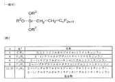
シランカップリング剤の一般式:

General formula of silane coupling agent:

原料微粒子11の表面にヒドロキシ基-OHがある場合には、カルボキシ基-COOHを有する反応分子13を作用させる。例えば、原料微粒子11と反応分子13とをそれぞれ適量秤量し、トルエンなどの有機溶媒中に分散させる。得られた分散液に、反応分子13の2倍当量程度のジシクロヘキシルカルボジイミドと、反応分子13の0.2倍当量程度のジメチルアミノピリジンを加えた後、室温下で1日攪拌する。反応終了後、トルエンおよびメタノールで洗浄し、濾過または遠心分離によって沈殿物を回収する。得られた沈殿物を真空乾燥し、粉末状のイオン伝導性微粒子1を得る。 <2. When using esterification reaction of carboxy group>
When the surface of the raw material
原料微粒子11の表面にヒドロキシ基-OHがある場合、第2の反応基Y14としてクロロスルホニル基-SO2Clを有するスルホニル化合物を反応分子13として用い、連結基Z6としてスルホン酸エステル結合を生成させることもできる。 <3. When using a chlorosulfonyl compound as a reaction molecule>
When the surface of the raw material

原料微粒子11は、表面構造を形成できるサイズ、例えば、外径が数nm~数μmのサイズの粒子である。表面にイオン解離性の基3を有しており、水素イオン解離性である場合には、スルホン酸基、ホスホノ基、カルボキシ基などの酸性基を有する。さらに、改質基4を導入するために、第1の反応基12が必要である。第1の反応基12は、例えば、ヒドロキシ基-OHやカルボキシ基-COOHやスルホン酸基-SO3Hである。イオン解離性の基3がスルホン酸基やカルボキシ基である場合には、この一部を第1の反応基12として用いてもよい。さらに、原料微粒子11は水に不溶であり、基材微粒子2が電子伝達性を持つもの、例えば導電性カーボン材料などは除かれる。 <Raw material fine particles>
The raw material
0<Wf<Ws・・・(式1)
これは、反応後もイオン伝導性微粒子1にイオン解離性の基3が残存し、イオン伝導性が失われない条件である。 In the system in which the ion
0 <Wf <Ws (Formula 1)
This is a condition in which the ion
P=Ws-Wf・・・(式2)
また、イオン伝導性複合体におけるイオン伝導性微粒子1とフッ素含有樹脂との質量比を1:Rとすると、イオン伝導性複合体膜におけるイオン解離性の基3の含有量(密度)Qは下記の(式3)で与えられる。
Q=(Ws-Wf)/(1+R)・・・(式3)
イオン伝導性複合体の電解質としての性能としては、このQが、Nafion(登録商標)の一般的なイオン交換容量約0.9mmol/gよりも大きいことが望ましい。後述する実施例1で得られたイオン伝導性複合体では、Qは2.24mmol/g以上であると算出され、非常にイオン交換容量の大きい電解質膜が得られることがわかる。 At this time, if the difference in mass between the raw material
P = Ws−Wf (Formula 2)
When the mass ratio of the ion conductive
Q = (Ws−Wf) / (1 + R) (Formula 3)
As an electrolyte performance of the ion conductive composite, it is desirable that this Q is larger than the general ion exchange capacity of Nafion (registered trademark) of about 0.9 mmol / g. In the ion conductive composite obtained in Example 1 described later, Q is calculated to be 2.24 mmol / g or more, and it can be seen that an electrolyte membrane having a very large ion exchange capacity can be obtained.
実施の形態2では、主として、請求項11~13に記載したイオン伝導性複合体、請求項9~11に記載した膜電極接合体(MEA)、および電気化学装置の例として、実施の形態1で作製した水素イオン伝導性微粒子を、図8を用いて説明した燃料電池20に適用した例について説明する。 [Embodiment 2]
In the second embodiment, the ion conductive composite according to
イオン伝導性複合体を作製するには、まず、イオン解離性の基を有するカーボンクラスター誘導体を適当な有機溶媒に加え、撹拌し、均一に分散させる。続いて、この分散液に、ポリフッ化ビニリデン(PVDF)またはその共重合体の粉末を加えて撹拌し、塗液を調製する。次に、このようにして調製した塗液を基材上に均一に塗り広げ、塗膜を形成する。この塗膜から溶媒を徐々に蒸発させ、膜状のイオン伝導性複合体を作製する。イオン伝導性複合体膜の厚さは、塗布する塗液の量によって制御することができる。 <Production of ion conductive composite>
In order to produce an ion conductive composite, first, a carbon cluster derivative having an ion dissociable group is added to a suitable organic solvent, and the mixture is stirred and uniformly dispersed. Subsequently, polyvinylidene fluoride (PVDF) or a copolymer powder thereof is added to the dispersion and stirred to prepare a coating solution. Next, the coating liquid prepared in this way is uniformly spread on the substrate to form a coating film. The solvent is gradually evaporated from the coating film to produce a film-like ion conductive composite. The thickness of the ion conductive composite film can be controlled by the amount of coating liquid to be applied.
上記のようにして作製した水素イオン伝導性複合体膜を適当な平面形状に切断する。これをアノード22とカソード23との間に挟み、例えば、温度130℃、圧力0.5kN/cm2の下で15分間加熱圧着することによって、膜電極接合体24を作製する。 <Production of membrane electrode assembly (MEA)>
The hydrogen ion conductive composite film produced as described above is cut into an appropriate planar shape. The
CH3OH+H2O→ CO2+6H++6e-・・・・・(4)
で示される反応によって酸化され、アノード22に電子を与える。生じた水素イオンH+は高分子電解質膜21を通ってカソ-ド23側へ移動する。カソ-ド触媒層23bに供給された酸素は、アノード側から移動してきた水素イオンと、カソ-ド触媒粒子上で下記の反応式(5)
(3/2)O2+6H++6e-→ 3H2O・・・・・(5)
で示される反応によって反応し、還元されてカソ-ド23から電子を取り込む。燃料電池全体では、(4)式と(5)式を合わせた、下記の反応式(6)
CH3OH+(3/2)O2→ CO2+2H2O・・・・(6)
で示される反応が起こる。 When the fuel cell is a direct methanol fuel cell (DMFC), the methanol of the fuel is supplied as an aqueous methanol solution or pure methanol, and evaporated methanol molecules reach the
CH 3 OH + H 2 O → CO 2 + 6H + + 6e − (4)
It is oxidized by the reaction shown in FIG. The generated hydrogen ion H + moves through the
(3/2) O 2 + 6H + + 6e − → 3H 2 O (5)
It is reduced by the reaction shown in FIG. In the whole fuel cell, the following reaction formula (6) is obtained by combining the formulas (4) and (5).
CH 3 OH + (3/2) O 2 → CO 2 + 2H 2 O (6)
The reaction indicated by
実施例1では、特許文献3に提案されている、スルホン酸基が導入された無定形炭素を、原料微粒子11として用いた。この材料は、有機化合物原料としてピッチ(コールタール)を用いて得られたものであるので、以下、スルホン化ピッチと呼ぶことにする。このスルホン化ピッチの元素分析結果を表1に示す。これから、スルホン化ピッチに含まれる硫黄Sがすべてスルホン酸基として存在していると仮定すると、スルホン酸基の含有量(密度)Wsは4.68mmol/gであると試算される。 <Raw material fine particles (fine particles having hydrogen ion dissociable groups)>
In Example 1, amorphous carbon introduced with a sulfonic acid group proposed in

上述したスルホン化ピッチを原料微粒子11として用い、これに対してフルオロアルキル基を有する改質基4を導入する処理を行った。まず、スルホン化ピッチを乳鉢で粉砕し、75μmメッシュのふるいを用いてふるい分けた。ふるいを通過した原料1.5gを無水トルエン20mL中に分散させ、純水75μLを加え、攪拌した。得られた懸濁液に2-(トリデカフルオロヘキシル)エチルトリエトキシシラン(東京化成工業(株)社製;製品番号T1770)75μLを徐々に滴下した。滴下終了後も懸濁液の攪拌を1~3日続け、反応を完了させた。 <Treatment of introducing the modifying
The above-mentioned sulfonated pitch was used as the raw material
フルオロアルキル基を有する改質基4を導入したスルホン化ピッチをγ-ブチロラクトン(和光純薬工業(株)社製、特級)に加え、2時間攪拌し、均一に分散させた。この分散液にPVDF粉末を添加し、必要ならさらに溶媒を添加して、80℃に保ちながら3時間以上攪拌し、均一に分散させた。 <Preparation of hydrogen ion conductive composite membrane>
The sulfonated pitch into which the modifying

P=(4.68-0.197)(mmol/g)
=4.483(mmol/g)
である。また、水素イオン伝導性複合体における、改質基4を導入したスルホン化ピッチとPVDFとの質量比を1:1とすると、水素イオン伝導性複合体膜におけるスルホン酸基の含有量(密度)Qは(式3)から、
Q=4.483/(1+1)(mmol/g)≒2.24(mmol/g)
で与えられる。実際には、シランカップリング剤の一部は、スルホン化ピッチと反応しなかったり、スルホン化ピッチがもつヒドロキシ基やカルボキシ基と反応したりするので、上記のPおよびQの値は考え得る限りの最小値であり、実際のPおよびQの値はこれより大きい。 Here, the content (density) of sulfonic acid groups in the hydrogen ion conductive composite membrane will be estimated. 75 μL of 2- (tridecafluorohexyl) ethyltriethoxysilane (molecular weight 510.4, density 1.34 g / mL) corresponds to 0.197 mmol. Therefore, in the above-described reaction of the silane coupling agent, 0.197 mmol of silane coupling agent is allowed to act on 1 g of the sulfonated pitch. Assuming that the total amount has reacted with the sulfonic acid group and the difference in mass between the sulfonated pitch and the sulfonated pitch into which the modifying
P = (4.68−0.197) (mmol / g)
= 4.483 (mmol / g)
It is. Further, when the mass ratio of the sulfonated pitch into which the modified
Q = 4.483 / (1 + 1) (mmol / g) ≈2.24 (mmol / g)
Given in. Actually, a part of the silane coupling agent does not react with the sulfonated pitch or reacts with the hydroxy group or carboxy group of the sulfonated pitch. The actual value of P and Q is larger than this.
上記の水素イオン伝導性複合体膜を14mm×14mmの正方形に切断し、電解質膜21として用いた。この電解質膜21を、平面形状が10mm×10mmの正方形であるアノード22とカソード23との間に挟み、温度130℃、圧力0.5kN/cm2の下で15分間加熱圧着して、膜電極接合体24を作製した。アノード22およびカソード23は、カーボンペーパー(商品名TPG-H-090;東レ(株)社製)からなる集電体に、触媒粒子とNafion(登録商標)分散液(商品名 DE-1021;デュポン社製)とを混合した塗液を塗布した後、溶媒を蒸発させ、触媒層を形成したガス拡散電極を用いた。各電極で用いた触媒粒子は、それぞれ、カーボンブラックに白金触媒Ptを担持させた担持触媒(田中貴金属工業(株)社製、白金担持量70%)、およびカーボンブラックに白金ルテニウム合金触媒PtRuを担持させた担持触媒(E-TEK社製、Pt:Ru=2:1)を用いた。 <Production of membrane electrode assembly (MEA) and fuel cell>
The hydrogen ion conductive composite membrane was cut into a 14 mm × 14 mm square and used as the
燃料電池20に対し、アノード22に燃料として純メタノールを供給し、自然吸気にてカソード23に空気を供給し、室温25℃で発電試験を行った。 <Power generation test of fuel cell>
For the
Claims (16)
- 基材微粒子の表面に
イオン解離性の基と、
一方の端部においてのみ前記基材微粒子の表面に結合し、他方の端部にイオン解離性の基をもたず、主部及び/又は前記他方の端部に、フッ素含有樹脂に対して親和性を有する原子団を含有する改質基と
を併せ持つ、イオン伝導性微粒子。 An ion dissociable group on the surface of the substrate fine particles,
It binds to the surface of the substrate fine particle only at one end, has no ion dissociable group at the other end, and has affinity for the fluorine-containing resin at the main part and / or the other end. Ion-conductive fine particles having a modifying group containing a functional atomic group. - 前記フッ素含有樹脂に対して親和性を有する原子団が、フッ素含有の有機基である、請求項1に記載したイオン伝導性微粒子。 The ion conductive fine particles according to claim 1, wherein the atomic group having affinity for the fluorine-containing resin is a fluorine-containing organic group.
- 前記フッ素含有の有機基がパーフルオロアルキル基を含有している、請求項2に記載したイオン伝導性微粒子。 The ion conductive fine particles according to claim 2, wherein the fluorine-containing organic group contains a perfluoroalkyl group.
- 前記基材微粒子がカーボンクラスター、無定形炭素微粒子、又はシリカ微粒子である、請求項1に記載したイオン伝導性微粒子。 The ion conductive fine particles according to claim 1, wherein the base fine particles are carbon clusters, amorphous carbon fine particles, or silica fine particles.
- 前記カーボンクラスターが、球状カーボンクラスター分子Cn(n=36、60、70、76、78、80、82、84等、通称フラーレン)からなる群の中から選ばれた少なくとも1種である、請求項4に記載したイオン伝導性微粒子。 The carbon cluster is at least one selected from the group consisting of spherical carbon cluster molecules C n (n = 36, 60, 70, 76, 78, 80, 82, 84, etc., commonly called fullerene). Item 5. The ion conductive fine particles described in Item 4.
- 前記イオン解離性の基が、プロトンH+、リチウムイオンLi+、ナトリウムイオンNa+、カリウムイオンK+、マグネシウムイオンMg2+、カルシウムイオンCa2+、ストロンチウムイオンSr2+、及びバリウムイオンBa2+のいずれかを含む、請求項1に記載したイオン伝導性微粒子。 The ion dissociable groups are proton H + , lithium ion Li + , sodium ion Na + , potassium ion K + , magnesium ion Mg 2+ , calcium ion Ca 2+ , strontium ion Sr 2+ , and barium ion Ba 2. The ion-conductive fine particles according to claim 1, comprising any of + .
- 前記イオン解離性の基が水素イオン解離性の基であり、水素イオン伝導性を有する、請求項6に記載したイオン伝導性微粒子。 The ion conductive fine particles according to claim 6, wherein the ion dissociable group is a hydrogen ion dissociable group and has hydrogen ion conductivity.
- 前記水素イオン解離性の基が、ヒドロキシ基-OH、スルホン酸基-SO3H、カルボキシ基-COOH、ホスホノ基-PO(OH)2、リン酸二水素エステル基-O-PO(OH)2、ホスホノメタノ基>CH(PO(OH)2)、ジホスホノメタノ基>C(PO(OH)2)2、ホスホノメチル基-CH2(PO(OH)2)、ジホスホノメチル基-CH(PO(OH)2)2、ホスフィン基-PHO(OH)、-PO(OH)-、及び-O-PO(OH)-からなる群の中から選ばれた1種以上の基である、請求項7に記載したイオン伝導性微粒子。 The hydrogen ion dissociable groups are a hydroxy group —OH, a sulfonic acid group —SO 3 H, a carboxy group —COOH, a phosphono group —PO (OH) 2 , and a dihydrogen phosphate group —O—PO (OH) 2. , Phosphonomethano group> CH (PO (OH) 2 ), diphosphonomethano group> C (PO (OH) 2 ) 2 , phosphonomethyl group —CH 2 (PO (OH) 2 ), diphosphonomethyl group —CH (PO (OH) 2 ) 2, phosphine groups -PHO (OH), - PO ( OH) -, and -O-PO (OH) - is composed of one or more groups selected from the group, ions of claim 7 Conductive fine particles.
- 基材微粒子の表面にイオン解離性の基と第1の反応基とを有する原料微粒子に対し、
一方の端部にのみ前記第1の反応基と結合し得る第2の反応基を有し、他方の端部に イオン解離性の基をもたず、主部及び/又は前記他方の端部にフッ素含有樹脂に対して 親和性を有する原子団を含有する反応分子を作用させ、
前記第1の反応基と前記第2の反応基との反応によって、前記基材微粒子の表面に一方の端部においてのみ結合し、他方の端部にイオン解離性の基をもたず、主部及び/又は前記他方の端部にフッ素含有樹脂に対して親和性を有する原子団を含有する改質基を導入する、
イオン伝導性微粒子の製造方法。 For the raw material fine particles having an ion dissociable group and a first reactive group on the surface of the substrate fine particles,
It has the 2nd reactive group which can couple | bond with the said 1st reactive group only at one edge part, does not have an ion dissociable group in the other edge part, and is the main part and / or said other edge part Reacts with a reactive molecule containing an atomic group having an affinity for fluorine-containing resin,
Due to the reaction between the first reactive group and the second reactive group, it is bonded to the surface of the base particle only at one end, and has no ion dissociable group at the other end. Introducing a modifying group containing an atomic group having an affinity for the fluorine-containing resin into a part and / or the other end,
A method for producing ion-conductive fine particles. - 前記反応を、前記反応分子としてシランカップリング剤を用いる反応、カルボキシ基のエステル化反応、又は前記反応分子としてクロロスルホニル化合物を用いる反応によって行う、請求項9に記載したイオン伝導性微粒子の製造方法。 The method for producing ion-conductive fine particles according to claim 9, wherein the reaction is performed by a reaction using a silane coupling agent as the reactive molecule, an esterification reaction of a carboxy group, or a reaction using a chlorosulfonyl compound as the reactive molecule. .
- 請求項1~8のいずれか1項に記載したイオン伝導性微粒子とフッ素含有樹脂とを含有する、イオン伝導性複合体。 An ion conductive composite comprising the ion conductive fine particles according to any one of claims 1 to 8 and a fluorine-containing resin.
- 前記フッ素含有樹脂が、フッ化ビニリデン、テトラフルオロエチレン、又はヘキサフルオロプロペンの単一重合体又は共重合体である、請求項11に記載したイオン伝導性複合体。 The ion conductive composite according to claim 11, wherein the fluorine-containing resin is a single polymer or copolymer of vinylidene fluoride, tetrafluoroethylene, or hexafluoropropene.
- 前記フッ化ビニリデンの共重合体が、ヘキサフルオロプロペンとの共重合体である、請求項12に記載したイオン伝導性複合体。 The ion conductive composite according to claim 12, wherein the copolymer of vinylidene fluoride is a copolymer with hexafluoropropene.
- 請求項11~13のいずれか1項に記載したイオン伝導性複合体が電解質として対向電極間に挟持されている、膜電極接合体。 A membrane electrode assembly, wherein the ion conductive composite according to any one of claims 11 to 13 is sandwiched between counter electrodes as an electrolyte.
- 請求項11~13のいずれか1項に記載した水素イオン伝導性複合体が電解質として対向電極間に挟持され、電気化学反応部を構成している、電気化学装置。 An electrochemical device in which the hydrogen ion conductive composite according to any one of claims 11 to 13 is sandwiched between counter electrodes as an electrolyte to constitute an electrochemical reaction unit.
- 燃料電池として構成された、請求項15に記載した電気化学装置。
The electrochemical device according to claim 15 configured as a fuel cell.
Priority Applications (2)
| Application Number | Priority Date | Filing Date | Title |
|---|---|---|---|
| US13/382,261 US20120100458A1 (en) | 2009-07-15 | 2010-07-07 | Ion-conducting microparticle and method of manufacturing the same, ion-conducting composite, membrane electrode assembly (mea), and electrochemical device |
| CN2010800305334A CN102473472A (en) | 2009-07-15 | 2010-07-07 | Ion-conducting particle and manufacturing method therefor, ion-conducting composite, membrane electrode assembly (MEA), and electrochemical device |
Applications Claiming Priority (2)
| Application Number | Priority Date | Filing Date | Title |
|---|---|---|---|
| JP2009-166293 | 2009-07-15 | ||
| JP2009166293A JP5444904B2 (en) | 2009-07-15 | 2009-07-15 | Method for producing ion-conductive fine particles |
Publications (1)
| Publication Number | Publication Date |
|---|---|
| WO2011007702A1 true WO2011007702A1 (en) | 2011-01-20 |
Family
ID=43449311
Family Applications (1)
| Application Number | Title | Priority Date | Filing Date |
|---|---|---|---|
| PCT/JP2010/061512 WO2011007702A1 (en) | 2009-07-15 | 2010-07-07 | Ion-conducting particle and manufacturing method therefor, ion-conducting composite, membrane electrode assembly (mea), and electrochemical device |
Country Status (4)
| Country | Link |
|---|---|
| US (1) | US20120100458A1 (en) |
| JP (1) | JP5444904B2 (en) |
| CN (1) | CN102473472A (en) |
| WO (1) | WO2011007702A1 (en) |
Cited By (2)
| Publication number | Priority date | Publication date | Assignee | Title |
|---|---|---|---|---|
| JP7025582B1 (en) * | 2021-06-07 | 2022-02-24 | 日本碍子株式会社 | Ionic conductive fine particles |
| JP7025581B1 (en) | 2021-06-07 | 2022-02-24 | 日本碍子株式会社 | Ionic conductive fine particles, electrolyte membranes for electrochemical cells, and methods for manufacturing them. |
Families Citing this family (2)
| Publication number | Priority date | Publication date | Assignee | Title |
|---|---|---|---|---|
| JP5644252B2 (en) * | 2009-08-20 | 2014-12-24 | セントラル硝子株式会社 | Solid electrolyte membrane for fuel cell and method for producing the same |
| WO2015190887A1 (en) * | 2014-06-13 | 2015-12-17 | 주식회사 엘지화학 | Composite electrolyte membrane and method for manufacturing same |
Citations (6)
| Publication number | Priority date | Publication date | Assignee | Title |
|---|---|---|---|---|
| WO2001006519A1 (en) * | 1999-07-19 | 2001-01-25 | Sony Corporation | Proton conducting material and method for preparing the same, and electrochemical device using the same |
| JP2003123793A (en) * | 2001-10-11 | 2003-04-25 | Sony Corp | Cation conductor and electrochemical device |
| JP2003303513A (en) * | 2002-02-05 | 2003-10-24 | Sony Corp | Proton conductor and its manufacturing method, proton conductive polymer and its manufacturing method, proton conductive polymer composition, and electrochemical device |
| JP2004055562A (en) * | 2002-07-19 | 2004-02-19 | Sony Corp | Ion conductor, its manufacturing method and electrochemical device |
| JP2005171086A (en) * | 2003-12-11 | 2005-06-30 | Samsung Sdi Co Ltd | Proton-conductive electrolyte and fuel cell |
| JP2006120816A (en) * | 2004-10-21 | 2006-05-11 | Renesas Technology Corp | Manufacturing method of semiconductor device |
Family Cites Families (2)
| Publication number | Priority date | Publication date | Assignee | Title |
|---|---|---|---|---|
| US6495290B1 (en) * | 1999-07-19 | 2002-12-17 | Sony Corporation | Proton conductor, production method thereof, and electrochemical device using the same |
| US6890676B2 (en) * | 2002-02-05 | 2005-05-10 | Sony Corporation | Fullerene based proton conductive materials |
-
2009
- 2009-07-15 JP JP2009166293A patent/JP5444904B2/en not_active Expired - Fee Related
-
2010
- 2010-07-07 US US13/382,261 patent/US20120100458A1/en not_active Abandoned
- 2010-07-07 CN CN2010800305334A patent/CN102473472A/en active Pending
- 2010-07-07 WO PCT/JP2010/061512 patent/WO2011007702A1/en active Application Filing
Patent Citations (6)
| Publication number | Priority date | Publication date | Assignee | Title |
|---|---|---|---|---|
| WO2001006519A1 (en) * | 1999-07-19 | 2001-01-25 | Sony Corporation | Proton conducting material and method for preparing the same, and electrochemical device using the same |
| JP2003123793A (en) * | 2001-10-11 | 2003-04-25 | Sony Corp | Cation conductor and electrochemical device |
| JP2003303513A (en) * | 2002-02-05 | 2003-10-24 | Sony Corp | Proton conductor and its manufacturing method, proton conductive polymer and its manufacturing method, proton conductive polymer composition, and electrochemical device |
| JP2004055562A (en) * | 2002-07-19 | 2004-02-19 | Sony Corp | Ion conductor, its manufacturing method and electrochemical device |
| JP2005171086A (en) * | 2003-12-11 | 2005-06-30 | Samsung Sdi Co Ltd | Proton-conductive electrolyte and fuel cell |
| JP2006120816A (en) * | 2004-10-21 | 2006-05-11 | Renesas Technology Corp | Manufacturing method of semiconductor device |
Cited By (3)
| Publication number | Priority date | Publication date | Assignee | Title |
|---|---|---|---|---|
| JP7025582B1 (en) * | 2021-06-07 | 2022-02-24 | 日本碍子株式会社 | Ionic conductive fine particles |
| JP7025581B1 (en) | 2021-06-07 | 2022-02-24 | 日本碍子株式会社 | Ionic conductive fine particles, electrolyte membranes for electrochemical cells, and methods for manufacturing them. |
| JP2022187232A (en) * | 2021-06-07 | 2022-12-19 | 日本碍子株式会社 | Ion-conducting fine particle, electrolyte membrane for electrochemical cell, and method for producing them |
Also Published As
| Publication number | Publication date |
|---|---|
| US20120100458A1 (en) | 2012-04-26 |
| CN102473472A (en) | 2012-05-23 |
| JP5444904B2 (en) | 2014-03-19 |
| JP2011023185A (en) | 2011-02-03 |
Similar Documents
| Publication | Publication Date | Title |
|---|---|---|
| Jiang et al. | Sulfonated poly (ether ether ketone) membranes with sulfonated graphene oxide fillers for direct methanol fuel cells | |
| KR100778502B1 (en) | Polymer membrane and membrane-electrode assembly for fuel cell and fuel cell system | |
| Hu et al. | Sulfonated poly (fluorenyl ether ketone)/Sulfonated α-zirconium phosphate Nanocomposite membranes for proton exchange membrane fuel cells | |
| WO2007029346A1 (en) | Proton conductive hybrid material, and catalyst layer for fuel cell using the same | |
| JP2007012616A (en) | Polyelectrolyte membrane for fuel cell, membrane - electrode assembly for fuel cell including the membrane and fuel cell system including the assembly | |
| Yuan et al. | Constructing a cathode catalyst layer of a passive direct methanol fuel cell with highly hydrophilic carbon aerogel for improved water management | |
| WO2006006357A1 (en) | Electrolyte membrane for solid polymer fuel cell, method for producing same and membrane electrode assembly for solid polymer fuel cell | |
| JP5021910B2 (en) | Modified inorganic material, composite electrolyte membrane, and fuel cell | |
| JP5444904B2 (en) | Method for producing ion-conductive fine particles | |
| WO2003003492A1 (en) | Proton conductor and electrochemical device using the same | |
| JP5696722B2 (en) | Membrane electrode assembly for polymer electrolyte fuel cell and method for producing cathode for polymer electrolyte fuel cell | |
| Elumalai et al. | Preparation of tungstic acid functionalized titanium oxide nanotubes and its effect on proton exchange membrane fuel cell | |
| Wang et al. | High performance proton exchange membranes with double proton conduction pathways by introducing MOF impregnated with protic ionic liquid into SPEEK | |
| JP4524579B2 (en) | Proton conductive composite and electrochemical device | |
| JP4534445B2 (en) | Ionic conductor, method for producing the same, and electrochemical device | |
| JP2005162623A (en) | Monomer compound, graft copolymer compound, method for producing the same, polyelectrolyte membrane and fuel cell | |
| US7977008B2 (en) | High temperature proton exchange membrane using ionomer/solid proton conductor, preparation method thereof and fuel cell containing the same | |
| CN107615545A (en) | Polymer dielectric film including its membrane electrode assembly and the fuel cell including the membrane electrode assembly | |
| JP2005521777A (en) | Ion exchange composites based on proton conducting silica particles dispersed in a polymer matrix | |
| JP2002075420A (en) | Electrochemical device and driving method | |
| JP5604818B2 (en) | Ion conductive composite, membrane electrode assembly (MEA), and electrochemical device | |
| Cui et al. | SCTF nanosheets@ sulfonated poly (p-phenylene-co-aryl ether ketone) composite proton exchange membranes for passive direct methanol fuel cells | |
| Nkazi | SYNTHESIS OF PROTON EXCHANGE MEMBRANE BASED ON SULFONATED POLYPHENYLSULFONE FOR FUEL CELL APPLICATIONS | |
| 黄亭維 | Development of Mesoporous Carbon Fibers as Novel Catalyst Supports for Polymer Electrolyte Fuel Cell | |
| Mohanapriya et al. | Electrolyte Membrane for 2D Nanomaterials |
Legal Events
| Date | Code | Title | Description |
|---|---|---|---|
| WWE | Wipo information: entry into national phase |
Ref document number: 201080030533.4 Country of ref document: CN |
|
| 121 | Ep: the epo has been informed by wipo that ep was designated in this application |
Ref document number: 10799761 Country of ref document: EP Kind code of ref document: A1 |
|
| WWE | Wipo information: entry into national phase |
Ref document number: 13382261 Country of ref document: US |
|
| NENP | Non-entry into the national phase |
Ref country code: DE |
|
| 122 | Ep: pct application non-entry in european phase |
Ref document number: 10799761 Country of ref document: EP Kind code of ref document: A1 |