WO2011007528A1 - 質量分析計及び質量分析方法 - Google Patents
質量分析計及び質量分析方法 Download PDFInfo
- Publication number
- WO2011007528A1 WO2011007528A1 PCT/JP2010/004464 JP2010004464W WO2011007528A1 WO 2011007528 A1 WO2011007528 A1 WO 2011007528A1 JP 2010004464 W JP2010004464 W JP 2010004464W WO 2011007528 A1 WO2011007528 A1 WO 2011007528A1
- Authority
- WO
- WIPO (PCT)
- Prior art keywords
- ion
- ions
- electrode
- ion trap
- ion guide
- Prior art date
- Legal status (The legal status is an assumption and is not a legal conclusion. Google has not performed a legal analysis and makes no representation as to the accuracy of the status listed.)
- Ceased
Links
Images


Classifications
-
- H—ELECTRICITY
- H01—ELECTRIC ELEMENTS
- H01J—ELECTRIC DISCHARGE TUBES OR DISCHARGE LAMPS
- H01J49/00—Particle spectrometers or separator tubes
- H01J49/004—Combinations of spectrometers, tandem spectrometers, e.g. MS/MS, MSn
-
- H—ELECTRICITY
- H01—ELECTRIC ELEMENTS
- H01J—ELECTRIC DISCHARGE TUBES OR DISCHARGE LAMPS
- H01J49/00—Particle spectrometers or separator tubes
- H01J49/0095—Particular arrangements for generating, introducing or analyzing both positive and negative analyte ions
Definitions
- the present invention relates to a mass spectrometer and an operation method thereof.
- An ion trap is a widely used mass spectrometer that accumulates ions and then selectively discharges them.
- Patent Documents 2 to 5 describe the configuration and measurement method of the ion trap.
- ions introduced from the ion source during the mass analysis are eliminated and lost, and thus there is a problem that the ion utilization efficiency is low. If ions introduced from an ion source during mass analysis using this ion trap can be used for mass analysis, the sensitivity of the ion trap can be improved.
- ions introduced from an ion source are accumulated in a two-dimensional multipole electric field formed by a multipole rod, and the ions are stored in the ion trap accumulation process.
- Patent Document 1 describes a method of improving ion utilization efficiency by introducing the ion.
- Patent Document 2 describes a method of increasing ion utilization efficiency by simultaneously mass-selectively discharging ions while accumulating ions in an ion trap.
- One of the problems of the present invention is to measure both positive ions and negative ions alternately with an ion trap mass spectrometer, and to improve ion utilization efficiency at that time.
- the positive ion measurement can be performed with a single chromatogram measurement by alternately switching between positive ion measurement and negative ion measurement of the mass spectrometer. And negative ion measurement data can be acquired.
- the number of measurement points is too small when performing quantitative analysis using a mass chromatogram, and therefore the measurement accuracy decreases.
- Patent Document 1 Although the use of positive ions is described in a measurement sequence using a pre-trap, there is no description in the case of measuring ions of opposite polarity alternately. This makes it impossible to store ions having a polarity opposite to that measured by the ion trap in the multipole electric field. Further, in the method described in Patent Document 2, the kinetic energy of ions introduced into the ion trap is not sufficiently cooled, and ions having high kinetic energy at the time of introduction are discharged regardless of mass, causing noise. / N is low. In the methods described in Patent Documents 3 to 5, the ions introduced from the ion source are eliminated during mass analysis using the ion trap, resulting in a loss, so that the ion utilization efficiency is low.
- an ion trap unit using an ion source that generates ions, an ion guide unit that transports the ions introduced from the ion source, and an ion trap unit that traps ions and selectively discharges ions.
- Examples of mass spectrometry methods include: an ion source that generates ions; an ion guide that transports ions introduced from the ion source; and an ion that traps ions introduced from the ion guide and selectively ejects ions.
- a trap unit a detector for detecting ions ejected from the ion trap unit, and a control unit.
- the control unit is mass-selective from the ion trap unit by voltage control of the ion guide unit and the ion trap unit. During the time when ions are discharged, ions having a polarity opposite to that of ions trapped in the ion trap portion are introduced into the ion guide portion.
- Examples of mass spectrometry methods include a step of introducing a first ion from an ion source into an ion guide, a step of introducing a first ion from an ion guide into an ion trap, and discharging the first ion from the ion trap. And analyzing, and in the analyzing step, accumulating second ions having a polarity opposite to the first ions in the ion guide.
- an electrode for controlling the passage of ions is provided between the ion guide portion and the ion trap portion, and the ion potential is controlled with respect to the potential of the electrode for controlling the passage of ions.
- the polarity of the offset potential of the multipole rod electrode of the guide portion and the offset potential of the ion trap portion may be reversed, and ions may be introduced from the ion guide into the ion trap.
- the height of the pseudopotential formed by the AC voltage is lower than the offset potential of the ion guide portion and higher than the offset potential of the ion trap portion, Ions may be introduced from the ion guide into the ion trap.
- a reverse polarity voltage is applied to the first electrode adjacent to the ion guide portion and the second electrode adjacent to the ion trap portion, which is provided between the ion guide portion and the ion trap portion. You may introduce
- high ion utilization efficiency can be obtained when both positive ions and negative ions are measured alternately with an ion trap mass spectrometer.
- An example of a structure of a mass spectrometer An example of a structure of an ion guide part. An example of a structure of an ion trap part. An example of a measurement sequence.
- Mass spectrum diagram An example of a structure of a mass spectrometer. An example of a measurement sequence. An example of a measurement sequence. Stability diagram.
- An example of ion guide An example of a structure of a mass spectrometer.
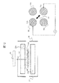
- FIG. 1 is a block diagram showing an embodiment of a mass spectrometer of the present invention. Note that the introduction mechanism of buffer gas or the like is omitted for the sake of simplicity.
- the ions generated by the ion source 1 such as an electrospray ion source, an atmospheric pressure chemical ion source, an atmospheric pressure photoion source, an atmospheric pressure matrix assisted laser desorption ion source, and a matrix assisted laser desorption ion source are the first pores 2. And is introduced into the first differential exhaust section 5.
- An ion source such as an electrospray ion source, an atmospheric pressure chemical ion source, or an atmospheric pressure photo ion source uses two needle electrodes, one of which has a positive high voltage of 500 V to 8000 V, and the other has a negative high voltage of 500 V. By applying ⁇ 8000 V, bipolar ions can be generated simultaneously.
- the first differential exhaust unit 5 is exhausted by a pump 40.
- the ions introduced into the first differential exhaust part 5 are introduced into the second differential exhaust part 6 through the inlet end electrode 3 of the ion guide part.
- the second differential exhaust section 6 is exhausted by a pump 41 and maintained at a pressure of about 10 ⁇ 4 Torr to 10 ⁇ 2 Torr (1.3 ⁇ 10 ⁇ 2 Pa to 1.3 Pa).
- An ion guide portion 31 is installed in the second differential exhaust portion 6.
- FIG. 2 shows the configuration of the ion guide portion 31.
- the ion guide portion 31 has a quadrupole rod electrode 10.
- the outlet end electrode 4 of the ion guide portion 31 also serves as a vacuum partition with the high vacuum chamber
- the inlet end electrode 3 of the ion guide portion also serves as a vacuum partition with the first differential exhaust portion.
- the quadrupole rod electrode 10 is applied with an RF voltage with an inverted phase generated by an RF power source.
- the typical voltage amplitude of this RF voltage is several hundred to 5000 V, and the frequency is about 500 kHz to 2 MHz.
- a plate-like blade electrode 11 is inserted in the gap between the quadrupole rods.
- the blade electrode 11 has a shape in which the distance between the end surface of the blade electrode and the center of the quadrupole is the smallest at the entrance of the ion guide portion and the distance is closer to the exit.
- a DC voltage By applying a DC voltage to the blade electrode 11, a gradient electric field can be formed on the central axis of the ion guide portion.
- no blade electrode is inserted into the gap between the quadrupole rods.
- the high vacuum chamber 7 is evacuated by a pump 42 and maintained at 10 ⁇ 4 Torr or less, and an ion trap part 32 and a detector 33 are installed.
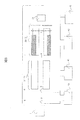
- FIG. 3 shows an example of the configuration of the ion trap unit 32.
- the illustrated ion trap 32 includes an inlet end electrode 27, an outlet end electrode 28, a quadrupole rod electrode 20, and a vane electrode 21 inserted in a gap between the quadrupole rod electrodes, a trap wire electrode 24, and an extraction wire electrode. 25.
- the quadrupole rod electrode 20 is applied with a trapped RF voltage having an inverted phase generated by an RF power source.
- the typical voltage amplitude of this RF voltage is several hundred to 5000 V, and the frequency is about 500 kHz to 2 MHz.
- a constant voltage offset potential ( ⁇ 100 to 100 V) may be applied to the quadrupole rod.
- the offset potential is set to 0 V as the value of the voltage applied to each electrode. Indicates the value when A buffer gas is introduced into the ion trap section 32 and is maintained at about 10 ⁇ 4 Torr to 10 ⁇ 2 Torr (1.3 ⁇ 10 ⁇ 2 Pa to 1.3 Pa).
- a wire electrode is used here, but any configuration that traps ions and selectively ejects ions may be used.
- the voltage, temperature, and the like of each part of the mass spectrometer can be controlled by the control unit 30.
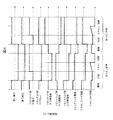
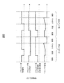
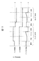
- FIG. 4 shows a measurement sequence when measuring positive ions and negative ions alternately.
- the first four sequences in FIG. 4 store negative ions in the ion guide unit 31 and perform a positive ion mass analysis in the ion trap unit 32, and the latter four sequences store positive ions in the ion guide unit 31.
- voltage application to each electrode during positive ion measurement will be described. What is necessary is just to reverse the polarity of the voltage applied at the time of a negative ion measurement.
- the ions accumulated in the ion guide unit 31 in the previous sequence and the ions introduced from the ion source in the accumulation step are accumulated in the ion trap.
- the potential of the outlet end electrode 4 of the ion guide part is set lower than the offset potential of the ion guide part 31, and ions are discharged from the ion guide part 31 toward the ion trap part.
- the inlet end electrode 27 of the ion trap part 32 is set lower than the offset potential of the ion guide part 31.
- the blade electrode 11 is set to 0V
- the trap wire electrode 24 is set to 20V
- the lead wire electrode 25 is set to 20V
- the outlet end electrode 28 is set to about 20V.
- a pseudo potential is formed by the trap RF voltage in the radial direction of the quadrupole.
- a DC potential is formed by the inlet end electrode 27 and the trap wire electrode 24 in the central axis direction of the quadrupole electric field. For this reason, the ions introduced into the ion trap portion 32 are trapped in the region 100 sandwiched between the inlet end electrode 27, the quadrupole rod electrode 20, the blade electrode 21, and the trap wire electrode 24.
- the accumulation process time depends on the amount of ions, but is usually about 10 to 1000 ms.
- the blade electrode 11 is inserted into the gap between the quadrupole rod electrodes 10 of the ion guide portion 31, and the blade electrode shape is formed so as to form a gradient electric field on the central axis of the ion guide portion 31.
- the configuration of FIG. 2B has an advantage that the number of parts is smaller than that of the configuration of FIG. 2A.
- the pressure of the ion guide portion 31 is high, ions near the inlet end electrode 3 are not.
- the ion guide part 31 is not discharged. After the ions trapped in the ion guide part 31 are introduced into the ion trap part, the ions introduced from the ion source pass through the ion guide part 31 and are introduced into the ion trap part 32.
- the ions trapped in the ion trap section 32 are cooled by collision with the buffer gas. Thereby, it is possible to prevent ions having a large momentum from being ejected independently of the mass in the mass scanning step.
- the inlet end electrode 27 is set to 10V
- the blade electrode 21 is set to 0V
- the trap electrode 24 is set to 20V
- the extraction electrode 25 is set to 20V
- the outlet end electrode 28 is set to about 20V.
- the RF voltage amplitude applied to the quadrupole rod electrode of the ion guide part 31 is set to 0, and all ions trapped in the ion guide part 31 are excluded.
- each electrode from the ion source 1 and the ion source to the entrance of the ion guide unit 31 is reversed.
- This ion source polarity switching may be performed in the mass scanning process, but it takes about 1-10 ms to stabilize the ion source after switching the polarity of the power source. appear. Loss can be reduced by switching the polarity of the ion source in the cooling process in which ions are excluded by the ion guide unit 31.
- an auxiliary AC voltage (amplitude 0.01 V to 100 V, frequency 10 kHz to 500 kHz) is applied between the blade electrodes 21.
- a voltage of about 1 to 30 V is applied to the trap wire electrode 24. Ions are resonantly ejected in a mass selective manner by changing the trap RF voltage amplitude.
- the relationship between the m / z of ions ejected at this time and the trap RF voltage amplitude (V) is expressed by the following equation.
- e is the elementary charge
- r 0 is the distance between the rod electrode 20 and the quadrupole center
- ⁇ is the angular frequency of the trap RF voltage.
- q ej is a numerical value that can be uniquely calculated from the ratio between the angular frequency ⁇ of the trap RF voltage and the auxiliary AC voltage angular frequency ⁇ .
- the ions discharged from the ion trap unit 32 in a mass selective manner are detected by the detector 33.
- ions having a polarity opposite to that of the ions being subjected to mass analysis by the ion trap unit 32 are introduced into the ion guide unit 31.
- the ions introduced into the ion guide portion 31 are trapped by the DC potential between the outlet end electrode 4 and the inlet end electrode 3 in the axial direction and by the pseudopotential formed by the quadrupole rod electrode 10 in the radial direction. .
- the RF voltage amplitude of the ion guide unit 31 By setting the RF voltage amplitude of the ion guide unit 31 to a value such that the q value of ions whose m / z is smaller than that of the analysis target is 0.9 or more, ions whose m / z is smaller than that of the analysis target are excluded, and space charge is performed. Can be reduced. Further, feedback may be applied to the time for accumulating ions in the ion guide unit 31 so as not to cause the space charge of the ion trap unit 32 from the total amount of ions detected by the detector 33.
- the trap RF voltage of the ion trap section 32 is set to 0, and all ions are discharged out of the trap.
- FIG. 3 schematically shows the trajectory 101 of ions ejected at this time.
- the time for the exclusion process is about 0.1 to 10 ms.
- the polarity of each electrode of the ion trap part 32 and the detector 33 is switched.
- the voltage applied to each electrode from the ion source 1 to the ion guide part 31 is the same as that in the mass scanning process, and ions introduced during the exclusion time are also trapped in the ion guide part 31.
- the ion utilization efficiency when the pre-trap in the ion guide part 31 is not performed is calculated.
- s be the mass scanning step
- e be the exclusion time
- c be the cooling step
- t be the accumulation time t.
- the ion utilization efficiency is expressed as (Equation 2). If the scanning process is 200 ms, the exclusion time is 5 ms, the cooling process is 10 ms, and the accumulation time is 50 ms, the ion utilization efficiency is 19%.
- the ion utilization efficiency is expressed as (Equation 3). If the scanning process is 200 ms, the exclusion time is 5 ms, the cooling process is 10 ms, and the accumulation time is 50 ms, the ion utilization efficiency is 96%. If the ions trapped in the ion guide portion 31 in the cooling process are not excluded, all the ions introduced into the cooling process can be used for analysis, so that the ion utilization efficiency is 100% in principle. . However, since some of the ions introduced from the ion source 1 may continue to remain in the ion guide portion 31, information on time variation of ions generated in the ion source, for example, information on retention time of the LC-MS, etc. Is lost.
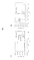
- FIG. 5 shows a mass spectrum measured by carrying out the present invention. Measurement is performed under the condition that the switching time of positive and negative ions is 0.5 seconds.
- TATP Triacetone triperoxide
- B pentaerythritol tetranitrate
- PETN Pentaerythritol tetranitrate
- Fig. 6 shows the apparatus configuration of Example 2.
- the ion trap section 32 is disposed in the high vacuum chamber 7 and is maintained at 0.1 ⁇ mTorr to 10 mTorr.
- the outlet end electrode 4 of the ion guide portion also serves as the inlet end electrode of the ion trap, but the other configuration is the same as that of the first embodiment.
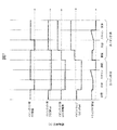
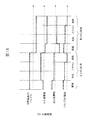
- the measurement sequence is shown in FIG.
- the voltage application from the ion source to the ion guide part 31 is the same as in the first embodiment.
- the offset potential of the quadrupole rod electrode of the ion trap portion 32 is changed, the voltage difference between the other electrodes of the ion trap portion 32 and the offset potential of the quadrupole rod electrode 20 is the same as that of the first embodiment.
- Interlocking control is performed so that it is the same as the applied voltage.
- voltage application to each electrode during positive ion measurement will be described. What is necessary is just to reverse the polarity of the voltage applied at the time of a negative ion measurement.
- the offset potential of the ion trap portion 32 is about 1 to 20 V lower than the outlet end electrode 4 of the ion guide portion 31, and the offset potential of the ion guide portion 31 is set to the outlet end electrode 4 of the ion guide portion 31.
- ions are introduced from the ion guide part 31 to the ion trap part 32 by setting the voltage higher by about 1 to 20V.
- the offset potential of the ion trap section 32 is set to be about 10 to 200 V lower than the outlet end electrode 4 of the ion guide section 31, and ions are trapped inside the ion trap.
- the offset potential of the ion guide portion 31 is set high by about 10 to 200 V, and negative ions introduced from the ion source are accumulated inside the ion guide.
- the voltage applied to the detector 33 may be controlled in accordance with the change in the offset potential of the ion trap unit 32. However, since a high voltage of ⁇ 2 kV to 6 kV is generally applied to the detector 33, the voltage is set to the offset potential. Regardless, even if a constant voltage is applied, there is almost no influence by the offset potential.
- Example 3 shows an example of a sequence operation when the same apparatus as in Example 2 is used.
- the height of the pseudo-potential of the outlet end electrode 4 is set to be higher than the offset potential of the ion guide portion 31 and introduced from the ion source 1 to the ion guide portion 31. Ions are trapped in the ion guide portion 31.
- the height of the pseudopotential of the outlet end electrode 4 of the ion guide part is set lower than the offset potential of the ion guide part 31 and higher than the offset potential of the ion trap part 32, and the ion guide part 31 to the ion trap part 32 are set. Ions are introduced into and accumulated in the ion trap.
- the height of the pseudopotential depends on the ion m / z
- ions in a wider m / z range can be trapped with high efficiency.
- neutral gas helium, nitrogen, argon, etc.
- Equipment configuration and measurement sequence are the same as in Example 1 and are omitted.
- the rod electrodes facing the quadrupole rod electrode 10 of the ion guide part 31 have the same phase and adjacent rod electrodes A quadrupole DC voltage is applied so that the phase is opposite.
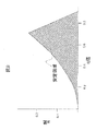
- the range of m / z of ions accumulated in the ion guide portion 31 is limited to the inside of the stability diagram of FIG.
- the q value is a value given by Equation 1
- the a value is a value given by (Equation 5) below.
- the m / z range of ions accumulated in the ion guide unit 31 is limited to a range including ions to be analyzed. be able to. Also, even if no quadrupole DC voltage is applied, if an alternating voltage having a specific frequency is applied to the opposing quadrupole rod electrode 10 or the blade electrode 11, ions of m / z that resonate with the applied frequency are generated. It can be selectively excluded from the ion guide part 31.
- the amount of ions accumulated in the ion trap part 32 is too large, there arises a problem that the mass axis of the mass spectrum shifts due to the effect of space charge.
- the range of ions accumulated in the ion guide part is avoided.
- the apparatus configuration other than the ion trap unit 32 and the measurement sequence are the same as those in the first embodiment, and will be omitted.
- the ion trap section 32 is disposed in the high vacuum chamber 7 and is maintained at 10 ⁇ 4 Torr to 10 ⁇ 2 Torr (1.3 ⁇ 10 ⁇ 2 Pa to 1.3 Pa).
- FIG. 11 shows a measurement sequence of the ion trap unit 32.
- voltage application to each electrode during positive ion measurement will be described. What is necessary is just to reverse the polarity of the voltage applied at the time of a negative ion measurement.
- a trap RF voltage (amplitude 100 V to 5000 V, frequency 500 kHz to 2 MHz) is applied to the quadrupole rod electrode 20.
- the inlet end electrode 27 is set to 5 to 20 V
- the outlet end electrode 28 is set to 10 to 50 V.
- a pseudopotential is formed by the trap RF voltage in the radial direction of the quadrupole electric field, and a DC potential is formed between the inlet end electrode 27 and the outlet end electrode 28 in the central axis direction of the quadrupole electric field. Therefore, ions introduced from the ion guide portion 31 are trapped in a region 100 surrounded by the inlet end electrode 27, the quadrupole rod electrode 20, and the outlet end electrode 28.
- an auxiliary AC voltage (amplitude 0.01 V to 1 V, frequency 10 kHz to 500 kHz) is applied between the opposing quadrupole rod electrodes 20 (a, c).
- the inlet end electrode 27 is set to 10 to 50V. Ions excited in the radial direction by the auxiliary AC voltage are ejected in the axial direction by a fringing field between the end of the quadrupole rod electrode 20 and the outlet end electrode 28.
- FIG. 10 schematically shows a trajectory 101 of ions ejected at this time. If the voltage at the outlet end electrode 28 is too low, unexcited ions are also discharged from the ion trap portion, and if it is too high, the discharge efficiency decreases.
- the voltage at the outlet end electrode 28 is set to a voltage at which only ions that are resonantly excited by the auxiliary AC voltage are ejected from the ion trap portion, and ions that are not resonantly excited are not ejected.
- a typical voltage is about 5V to 30V.
- a mass spectrum can be obtained by scanning the trap RF voltage amplitude from the lower (100 V to 1000 V) to the higher (500 V to 5000 V). The length of the mass scan time is about 10 ms to 500 ms, and is almost proportional to the mass range to be detected.
- the trap RF voltage is set to 0 and all ions are discharged out of the trap. The time for the exclusion process is about 1 ms.
- Example 1 has a higher ratio (discharge efficiency) of trapped ions to be selectively discharged from the inner mass.
- the apparatus configuration other than the ion trap unit 32 and the measurement sequence are the same as those in the first embodiment, and will be omitted.
- the ion trap section 32 is disposed in the high vacuum chamber 7 and is supplied with a buffer gas and is maintained at 10 ⁇ 6 Torr to 10 ⁇ 2 Torr (1.3 ⁇ 10 ⁇ 4 Pa to 1.3 Pa).
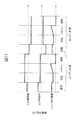
- FIG. 13 shows the measurement sequence of the ion trap section.
- voltage application to each electrode during positive ion measurement will be described. What is necessary is just to reverse the polarity of the voltage applied at the time of a negative ion measurement.
- a trap RF voltage (amplitude 100 V to 5000 V, frequency 500 kHz to 2 MHz) is applied to the quadrupole rod electrode 20.
- the inlet end electrode 27 is set to 5 to 20V
- the outlet end electrode 28 is set to 10 to 50V.
- a pseudopotential is formed by the trap RF voltage in the radial direction of the quadrupole electric field, and a DC potential is formed between the inlet end electrode 27 and the outlet end electrode 28 in the central axis direction of the quadrupole electric field. Therefore, in Example 5, as shown in FIG.
- an auxiliary AC voltage (amplitude 5 V to 100 V, frequency 10 kHz to 500 kHz) is applied between a pair of opposed quadrupole rod electrodes.
- FIG. 13 shows an example of voltages applied to other electrodes.
- the inlet end electrode 27 is set to about 10 to 50V
- the outlet side end electrode 28 is set to about 10 to 50V.
- the voltage at the outlet end electrode 28 in the mass scanning process may be the same voltage as in the accumulation process.
- Ions excited in the radial direction by the auxiliary AC voltage are ejected in the radial direction through the slots 60 formed in the quadrupole rod electrode 2.
- FIG. 12 schematically shows the trajectory 101 of ions ejected at this time.
- the detector 33 is provided outside the quadrupole rod electrode 20.
- a mass spectrum can be obtained by scanning the trap RF voltage amplitude from the lower (100 V to 1000 V) to the higher (500 V to 5000 V).
- the length of the mass scan time is about 10 ms to 200 ms, and is almost proportional to the mass range to be detected.
- the trap RF voltage is set to 0 and all ions are discharged out of the trap.
- the length of the exclusion process is about 1 ms.
- the configuration of the sixth embodiment has an advantage that the discharge efficiency is higher than that of the first embodiment.
- the energy dispersion of ions selectively ejected by mass is smaller in the first embodiment, the introduction efficiency into the ion optical system at the subsequent stage is higher in the first embodiment.
- the ion trap section 32 includes an inlet end electrode 27, an outlet end electrode 28, a quadrupole rod electrode 20, and a blade electrode 200 inserted in a gap between the quadrupole rod electrodes.
- the blade electrode 200 is an electrode having a shape that optimizes the potential on the central axis of the ion trap.
- the blade electrode 200 has an arc-like depression, and is inserted between the quadrupole rod electrodes 203 so that the side having the arc faces the central axis.
- the blade electrode 200 is divided into two in the central axis direction (refers to 200a and 200e, 200b and 200f, 200c and 200g, 200d and 200h).
- a buffer gas is introduced into the ion trap section 32 and is maintained at 10 ⁇ 4 Torr to 10 ⁇ 2 Torr (1.3 ⁇ 10 ⁇ 2 Pa to 1.3 Pa).
- FIG. 15 shows the measurement sequence of the ion trap section.
- voltage application to each electrode during positive ion measurement will be described. What is necessary is just to reverse the polarity of the voltage applied at the time of a negative ion measurement.
- a trap RF voltage (amplitude 100 V to 5000 V, frequency 500 kHz to 2 MHz) is applied to the quadrupole rod electrode 20. Further, a DC voltage of 10 to 100 V is applied to the blade electrode 200. As an example of the voltage applied to the other electrodes, the inlet end electrode 27 is set to 5 to 20V, and the outlet end electrode 28 is set to 10 to 100V.
- a pseudo potential is formed by the trap RF voltage in the radial direction of the quadrupole electric field, and a harmonic potential is formed by a DC bias between the blade electrode 200 and the quadrupole rod electrode 20 in the central axis direction of the quadrupole electric field.
- Example 7 the introduced ions are trapped in the region 100 surrounded by the blade electrode 200 and the quadrupole rod electrode 20.
- an auxiliary AC voltage (amplitude 0.01 V to 1 V, frequency 10 kHz to 500 kHz) is applied to the blade electrode 200 in addition to the DC voltage (20 to 300 V).
- the phase of the auxiliary AC voltage is between the blade electrodes adjacent in the radial direction and facing each other (in the figure (200a, 200b, 200c, 200d) and (200e, 200f, 200g, 200h)), the blade electrodes facing in the same phase and axial direction.
- the phase is reversed in the interval ((200a, 200e), (200b, 200f), (200c, 200g) and (200d, 200h)).
- the outlet end electrode 28 is set to about 0V to 10V
- the inlet end electrode 27 is set to about 10V to 100V.
- Ions excited in a mass selective manner by the auxiliary AC voltage are ejected in the axial direction.
- FIG. 14 schematically shows the trajectory 101 of ions ejected at this time.
- a mass spectrum can be obtained by scanning the frequency of the auxiliary AC voltage from higher (300 to 500 kHz) to lower (10 to 50 kHz), or from lower to higher.
- the time of the mass scanning process is about 10 ms to 200 ms, and is almost proportional to the mass range to be detected.
- the trap RF voltage is set to 0 and all ions are discharged out of the trap.
- the time for the exclusion process is about 1 ms.
- the configuration of the seventh embodiment has an advantage that the discharge efficiency is higher than that of the first embodiment. On the other hand, the number of ions that can be trapped at a time is larger in Example 1.
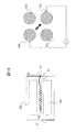
- FIG. 16 shows the configuration of the ion guide portion 31 of the eighth embodiment.
- the apparatus configuration other than the ion guide unit 31 and the measurement sequence are the same as those in the first embodiment, and will be omitted.
- the pressure of the ion guide portion 31 is maintained at about 10 ⁇ 4 Torr to 10 ⁇ 2 Torr (1.3 ⁇ 10 ⁇ 2 Pa to 1.3 Pa).
- the ion guide portion 32 of the eighth embodiment has a configuration in which two or more ring electrodes 400 are arranged in place of the quadrupole rod of the ion guide portion of the first embodiment so that the centers of the rings are coaxial. .
- the configuration of the eighth embodiment has an advantage that ions in a wider mass range can be efficiently accumulated and transmitted.
- the first embodiment has a simple structure and a smaller number of parts.
- ions selectively ejected from the ion trap unit 32 are introduced into the collisional dissociation unit 74.
- the collision dissociation part 74 is formed by an inlet end electrode 71, a multipole rod electrode 75, and an outlet end electrode 72, and nitrogen, Ar, or the like of about 1 mTorr to 30 mTorr (0.13 Pa to 4 Pa) is introduced therein. Ions introduced from the pores 70 are dissociated at the collisional dissociation part 74.
- the potential difference between the offset potential of the ion guide part 32 and the offset potential of the multipole rod electrode 75 is set to about 20V to 100V.
- the collisional dissociation can proceed.
- the fragment ions generated by dissociation are introduced into the time-of-flight mass analyzer 85.
- the time-of-flight mass spectrometer is maintained at 10 ⁇ 6 Torr or less (1.3 ⁇ 10 ⁇ 4 Pa or less).
- a collision dissociation chamber composed of four rod-shaped electrodes is illustrated, but the number of rod electrodes may be 6, 8, 10 or more, and a large number of lens-shaped electrodes.
- the arrangement may be such that RF voltages having different phases are applied to each.
- the time-of-flight mass spectrometer 85 includes an ion lens 300, an extrusion electrode 301, an extraction electrode 302, a reflection lens 303, and a detector 304.
- the ions introduced into the time-of-flight analysis unit are focused by an ion lens 300 composed of a plurality of electrodes, and then the acceleration unit of the time-of-flight mass analysis unit composed of the push-out electrode 301 and the pull-in electrode 302 Introduced into By applying a voltage of several hundreds V to several kV between the extrusion electrode 301 and the extraction electrode 302 by the acceleration unit power source, ions are accelerated in the ion introduction direction and the orthogonal direction.
- the ions accelerated in the orthogonal direction reach the detector as they are, or after being deflected through a reflection lens called a reflectron, reach the detector 304 made of MCP or the like. From the relationship between the acceleration start time of the acceleration unit and the ion detection time, the mass number of ions can be measured.
- a quadrupole ion guide is used for the ion guide portion 31; Further, the ion trap part 32 may be a three-dimensional quadrupole ion trap. It will be apparent that the invention may be practiced otherwise than as particularly described in the foregoing description and examples. As such, many modifications and variations of the present invention are possible and, therefore, are within the scope of the claims appended hereto.
- Region where ions are trapped 101 ... Mass trajectory of ions to be ejected, 60 ... Slit, 61 ... Fringing field, 200 ... Blade electrode, 400 ... Ring electrode, 70 ... Fine pore, 71 ... Inlet end electrode, 72 ... Mouth end electrode, 74 ... collision dissociation unit, 75 ... quadrupole rod electrodes, 300 ... ion lens, 301 ... extruded electrode, 302 ... lead-out electrode, 303 ... Reflector 304 ... detector
Landscapes
- Chemical & Material Sciences (AREA)
- Analytical Chemistry (AREA)
- Electron Tubes For Measurement (AREA)
- Other Investigation Or Analysis Of Materials By Electrical Means (AREA)
Priority Applications (1)
| Application Number | Priority Date | Filing Date | Title |
|---|---|---|---|
| US13/383,371 US8835834B2 (en) | 2009-07-15 | 2010-07-09 | Mass spectrometer and mass spectrometry method |
Applications Claiming Priority (2)
| Application Number | Priority Date | Filing Date | Title |
|---|---|---|---|
| JP2009-166279 | 2009-07-15 | ||
| JP2009166279A JP5481115B2 (ja) | 2009-07-15 | 2009-07-15 | 質量分析計及び質量分析方法 |
Publications (1)
| Publication Number | Publication Date |
|---|---|
| WO2011007528A1 true WO2011007528A1 (ja) | 2011-01-20 |
Family
ID=43449140
Family Applications (1)
| Application Number | Title | Priority Date | Filing Date |
|---|---|---|---|
| PCT/JP2010/004464 Ceased WO2011007528A1 (ja) | 2009-07-15 | 2010-07-09 | 質量分析計及び質量分析方法 |
Country Status (3)
| Country | Link |
|---|---|
| US (1) | US8835834B2 (enExample) |
| JP (1) | JP5481115B2 (enExample) |
| WO (1) | WO2011007528A1 (enExample) |
Families Citing this family (11)
| Publication number | Priority date | Publication date | Assignee | Title |
|---|---|---|---|---|
| JP5771456B2 (ja) * | 2011-06-24 | 2015-09-02 | 株式会社日立ハイテクノロジーズ | 質量分析方法 |
| JP5947567B2 (ja) | 2012-03-02 | 2016-07-06 | 株式会社日立ハイテクノロジーズ | 質量分析システム |
| JP5927089B2 (ja) * | 2012-09-14 | 2016-05-25 | 株式会社日立ハイテクノロジーズ | 質量分析装置及び方法 |
| EP3033763B1 (en) * | 2013-08-13 | 2021-05-26 | Purdue Research Foundation | Sample quantitation with a miniature mass spectrometer |
| US8907272B1 (en) * | 2013-10-04 | 2014-12-09 | Thermo Finnigan Llc | Radio frequency device to separate ions from gas stream and method thereof |
| US9837256B2 (en) * | 2013-12-24 | 2017-12-05 | Dh Technologies Development Pte. Ltd. | Simultaneous positive and negative ion accumulation in an ion trap for mass spectroscopy |
| WO2018069982A1 (ja) * | 2016-10-11 | 2018-04-19 | 株式会社島津製作所 | イオンガイド及び質量分析装置 |
| US11728153B2 (en) * | 2018-12-14 | 2023-08-15 | Thermo Finnigan Llc | Collision cell with enhanced ion beam focusing and transmission |
| GB2605395B (en) * | 2021-03-30 | 2024-12-11 | Thermo Fisher Scient Bremen Gmbh | Ion trap |
| CN116403884A (zh) * | 2021-12-27 | 2023-07-07 | 昆山禾信质谱技术有限公司 | 飞行时间质谱仪及其离子囚禁释放装置、控制方法 |
| JP2024029800A (ja) * | 2022-08-23 | 2024-03-07 | 株式会社日立ハイテク | イオンガイド、およびそれを備える質量分析装置 |
Citations (5)
| Publication number | Priority date | Publication date | Assignee | Title |
|---|---|---|---|---|
| JP2001176444A (ja) * | 1999-12-15 | 2001-06-29 | Jeol Ltd | 垂直加速型飛行時間型質量分析装置 |
| JP2007095702A (ja) * | 1995-08-11 | 2007-04-12 | Mds Health Group Ltd | 軸電界を有する分析計 |
| JP2007232728A (ja) * | 2007-03-29 | 2007-09-13 | Hitachi Ltd | 質量分析計 |
| WO2008071967A2 (en) * | 2006-12-12 | 2008-06-19 | Micromass Uk Limited | Mass spectrometer |
| JP2009117388A (ja) * | 2005-10-31 | 2009-05-28 | Hitachi Ltd | 質量分析装置 |
Family Cites Families (7)
| Publication number | Priority date | Publication date | Assignee | Title |
|---|---|---|---|---|
| US5179278A (en) | 1991-08-23 | 1993-01-12 | Mds Health Group Limited | Multipole inlet system for ion traps |
| US5420425A (en) | 1994-05-27 | 1995-05-30 | Finnigan Corporation | Ion trap mass spectrometer system and method |
| US5783824A (en) | 1995-04-03 | 1998-07-21 | Hitachi, Ltd. | Ion trapping mass spectrometry apparatus |
| US6177668B1 (en) | 1996-06-06 | 2001-01-23 | Mds Inc. | Axial ejection in a multipole mass spectrometer |
| US7026613B2 (en) * | 2004-01-23 | 2006-04-11 | Thermo Finnigan Llc | Confining positive and negative ions with fast oscillating electric potentials |
| JP4384542B2 (ja) * | 2004-05-24 | 2009-12-16 | 株式会社日立ハイテクノロジーズ | 質量分析装置 |
| GB0511386D0 (en) * | 2005-06-03 | 2005-07-13 | Shimadzu Res Lab Europe Ltd | Method for introducing ions into an ion trap and an ion storage apparatus |
-
2009
- 2009-07-15 JP JP2009166279A patent/JP5481115B2/ja not_active Expired - Fee Related
-
2010
- 2010-07-09 WO PCT/JP2010/004464 patent/WO2011007528A1/ja not_active Ceased
- 2010-07-09 US US13/383,371 patent/US8835834B2/en not_active Expired - Fee Related
Patent Citations (5)
| Publication number | Priority date | Publication date | Assignee | Title |
|---|---|---|---|---|
| JP2007095702A (ja) * | 1995-08-11 | 2007-04-12 | Mds Health Group Ltd | 軸電界を有する分析計 |
| JP2001176444A (ja) * | 1999-12-15 | 2001-06-29 | Jeol Ltd | 垂直加速型飛行時間型質量分析装置 |
| JP2009117388A (ja) * | 2005-10-31 | 2009-05-28 | Hitachi Ltd | 質量分析装置 |
| WO2008071967A2 (en) * | 2006-12-12 | 2008-06-19 | Micromass Uk Limited | Mass spectrometer |
| JP2007232728A (ja) * | 2007-03-29 | 2007-09-13 | Hitachi Ltd | 質量分析計 |
Also Published As
| Publication number | Publication date |
|---|---|
| JP2011023184A (ja) | 2011-02-03 |
| JP5481115B2 (ja) | 2014-04-23 |
| US8835834B2 (en) | 2014-09-16 |
| US20120112059A1 (en) | 2012-05-10 |
Similar Documents
| Publication | Publication Date | Title |
|---|---|---|
| JP5481115B2 (ja) | 質量分析計及び質量分析方法 | |
| JP5001965B2 (ja) | 質量分析装置 | |
| JP5603246B2 (ja) | 質量分析装置 | |
| EP2309531B1 (en) | Mass spectrometer | |
| JP4918846B2 (ja) | 質量分析装置及び質量分析方法 | |
| CN104126116B (zh) | 用于离子迁移谱的设备和方法 | |
| US7800058B2 (en) | Mass spectrometer and mass spectrometry method | |
| JP5124293B2 (ja) | 質量分析計および質量分析方法 | |
| JP5262010B2 (ja) | 質量分析計及び質量分析方法 | |
| US8927928B2 (en) | Method for operating a time-of-flight mass spectrometer with orthogonal ion pulsing | |
| US10665441B2 (en) | Methods and apparatus for improved tandem mass spectrometry duty cycle | |
| US20130001415A1 (en) | Frequency scan linear ion trap mass spectrometry | |
| JP4636943B2 (ja) | 質量分析装置 | |
| JP4709024B2 (ja) | 反応装置及び質量分析装置 | |
| CN114616647A (zh) | 傅立叶变换质谱法的方法和系统 | |
| CN112534547B (zh) | Rf离子阱离子加载方法 | |
| Agarwal et al. | A review on analyzers for mass spectrometry | |
| CN108593759A (zh) | 用于定量质量分析的方法和系统 | |
| JP3946162B2 (ja) | イオントラップ質量分析方法及び装置 | |
| WO2019211918A1 (ja) | 直交加速飛行時間型質量分析装置 |
Legal Events
| Date | Code | Title | Description |
|---|---|---|---|
| 121 | Ep: the epo has been informed by wipo that ep was designated in this application |
Ref document number: 10799592 Country of ref document: EP Kind code of ref document: A1 |
|
| WWE | Wipo information: entry into national phase |
Ref document number: 13383371 Country of ref document: US |
|
| NENP | Non-entry into the national phase |
Ref country code: DE |
|
| 122 | Ep: pct application non-entry in european phase |
Ref document number: 10799592 Country of ref document: EP Kind code of ref document: A1 |