WO2011004745A1 - 通信端末および通信制御方法 - Google Patents
通信端末および通信制御方法 Download PDFInfo
- Publication number
- WO2011004745A1 WO2011004745A1 PCT/JP2010/061139 JP2010061139W WO2011004745A1 WO 2011004745 A1 WO2011004745 A1 WO 2011004745A1 JP 2010061139 W JP2010061139 W JP 2010061139W WO 2011004745 A1 WO2011004745 A1 WO 2011004745A1
- Authority
- WO
- WIPO (PCT)
- Prior art keywords
- communication
- state
- unit
- communication terminal
- terminal
- Prior art date
Links
Images


Classifications
-
- H—ELECTRICITY
- H04—ELECTRIC COMMUNICATION TECHNIQUE
- H04W—WIRELESS COMMUNICATION NETWORKS
- H04W52/00—Power management, e.g. TPC [Transmission Power Control], power saving or power classes
- H04W52/02—Power saving arrangements
- H04W52/0209—Power saving arrangements in terminal devices
- H04W52/0225—Power saving arrangements in terminal devices using monitoring of external events, e.g. the presence of a signal
- H04W52/0245—Power saving arrangements in terminal devices using monitoring of external events, e.g. the presence of a signal according to signal strength
-
- H—ELECTRICITY
- H04—ELECTRIC COMMUNICATION TECHNIQUE
- H04B—TRANSMISSION
- H04B1/00—Details of transmission systems, not covered by a single one of groups H04B3/00 - H04B13/00; Details of transmission systems not characterised by the medium used for transmission
- H04B1/74—Details of transmission systems, not covered by a single one of groups H04B3/00 - H04B13/00; Details of transmission systems not characterised by the medium used for transmission for increasing reliability, e.g. using redundant or spare channels or apparatus
-
- H—ELECTRICITY
- H04—ELECTRIC COMMUNICATION TECHNIQUE
- H04W—WIRELESS COMMUNICATION NETWORKS
- H04W4/00—Services specially adapted for wireless communication networks; Facilities therefor
- H04W4/80—Services using short range communication, e.g. near-field communication [NFC], radio-frequency identification [RFID] or low energy communication
-
- H—ELECTRICITY
- H04—ELECTRIC COMMUNICATION TECHNIQUE
- H04W—WIRELESS COMMUNICATION NETWORKS
- H04W52/00—Power management, e.g. TPC [Transmission Power Control], power saving or power classes
- H04W52/02—Power saving arrangements
- H04W52/0209—Power saving arrangements in terminal devices
- H04W52/0225—Power saving arrangements in terminal devices using monitoring of external events, e.g. the presence of a signal
- H04W52/0241—Power saving arrangements in terminal devices using monitoring of external events, e.g. the presence of a signal where no transmission is received, e.g. out of range of the transmitter
-
- H—ELECTRICITY
- H04—ELECTRIC COMMUNICATION TECHNIQUE
- H04W—WIRELESS COMMUNICATION NETWORKS
- H04W52/00—Power management, e.g. TPC [Transmission Power Control], power saving or power classes
- H04W52/02—Power saving arrangements
- H04W52/0209—Power saving arrangements in terminal devices
- H04W52/0251—Power saving arrangements in terminal devices using monitoring of local events, e.g. events related to user activity
-
- H—ELECTRICITY
- H04—ELECTRIC COMMUNICATION TECHNIQUE
- H04W—WIRELESS COMMUNICATION NETWORKS
- H04W76/00—Connection management
- H04W76/10—Connection setup
- H04W76/14—Direct-mode setup
-
- H—ELECTRICITY
- H04—ELECTRIC COMMUNICATION TECHNIQUE
- H04W—WIRELESS COMMUNICATION NETWORKS
- H04W76/00—Connection management
- H04W76/20—Manipulation of established connections
- H04W76/27—Transitions between radio resource control [RRC] states
-
- Y—GENERAL TAGGING OF NEW TECHNOLOGICAL DEVELOPMENTS; GENERAL TAGGING OF CROSS-SECTIONAL TECHNOLOGIES SPANNING OVER SEVERAL SECTIONS OF THE IPC; TECHNICAL SUBJECTS COVERED BY FORMER USPC CROSS-REFERENCE ART COLLECTIONS [XRACs] AND DIGESTS
- Y02—TECHNOLOGIES OR APPLICATIONS FOR MITIGATION OR ADAPTATION AGAINST CLIMATE CHANGE
- Y02D—CLIMATE CHANGE MITIGATION TECHNOLOGIES IN INFORMATION AND COMMUNICATION TECHNOLOGIES [ICT], I.E. INFORMATION AND COMMUNICATION TECHNOLOGIES AIMING AT THE REDUCTION OF THEIR OWN ENERGY USE
- Y02D30/00—Reducing energy consumption in communication networks
- Y02D30/70—Reducing energy consumption in communication networks in wireless communication networks
Definitions
- the present invention relates to a communication terminal having a plurality of different communication means and a communication control method.
- Patent Literature 1 describes a communication system that performs communication using a non-contact IC card and communication using Bluetooth (Bluetooth (registered trademark)) between a personal computer and a mobile phone.
- Bluetooth Bluetooth (registered trademark)
- the mobile phone approaches the personal computer
- communication using a non-contact IC card is performed between the two and the personal computer acquires the card ID of the non-contact IC card from the mobile phone.
- the personal computer identifies a mobile phone that performs communication using Bluetooth based on the acquired card ID, and establishes communication.
- the above-described conventional communication system has different communication distances for a plurality of communication interfaces, it is not considered that other communication interfaces are activated or disconnected based on the communication distance. Therefore, for example, when communication is disconnected at a distance between communication terminals from a state where two communication interfaces are simultaneously linked to perform communication, a communication interface having a long communication distance is changed to a communication interface having a short communication distance. In comparison, it takes time until communication is disconnected. As a result, there is a problem in that the amount of power consumption increases due to the time taken to disconnect.
- the communication range of the communication interface with a short communication distance When a communication terminal enters, a communication interface with a short communication distance is activated and communication is possible. As described above, since the communication interface with a short communication distance is activated after entering the communication area of the communication interface with a short communication distance, there is a problem that it takes time until the communication is started.
- an object of the present invention is to provide a communication terminal and a communication control method capable of efficiently controlling activation or disconnection of communication means in a communication terminal having a plurality of different communication means.
- the present invention relates to a communication terminal provided with a plurality of communication means having different communication distances, and a communication area within which a distance between one communication means and another communication terminal communicating with the communication terminal can be communicated. Or a communication status detection means for detecting a service status indicating whether it is out of a communication range where communication is not possible, and other communication means according to the service status detected by the service status detection means. Communication state management means for transitioning to an activated state, a standby state, or a disconnected state.
- the present invention provides a communication control method for a communication terminal provided with a plurality of communication means having different communication distances, and the distance between one communication means among the plurality of communication means and another communication terminal that communicates with the communication terminal.
- a visitor state detection step for detecting whether the visitor is in a communicable communication range or out of a communicable communication range, and depending on the present state detected by the present state detection step
- a communication state management step for causing other communication means to transition to an activated state, a standby state, or a disconnected state.
- the communication state management means sets the other communication means in a standby state or a disconnected state when the presence state of one communication means having the shortest communication distance among a plurality of communication means transitions from the communication range to the outside of the communication range. It is preferable to make transition to.
- the other communication means can be set in a standby state or a disconnected state without waiting for the other communication means to be disconnected outside the communication range, thereby reducing power consumption by the communication means. it can.
- the communication state management unit causes the other communication unit to transition to the activated state when the presence state of the one communication unit having the longest communication distance among the plurality of communication units transitions from the outside of the communication range to the communication range. Is preferred. Thereby, when trying to start communication by linking a plurality of communication means, when the communication means with the longest communication distance enters the communication range, the other communication means is activated in advance. Communication can be started immediately after the communication means enters the communication range.
- activation or disconnection of communication means can be efficiently controlled in a communication terminal provided with a plurality of different communication means.
- FIG. 1 is a block diagram showing a functional configuration of the communication system 1.
- the communication terminal 10 includes a first communication unit 11 (communication means) and a second communication unit 12 (communication means) that communicate with the personal computer 50, and a located state detecting unit 13 (located state detecting means). ) And a communication state management unit 14 (communication state management means).
- a communication terminal having a voice call function to which the function of the communication terminal according to the present invention is applied is used.
- the personal computer 50 (other communication terminal) functionally includes a first communication unit 51 and a second communication unit 52 that communicate with the communication terminal 10.
- FIG. 2 is a hardware configuration diagram of the communication terminal 10.
- the communication terminal 10 physically includes a CPU 101, a RAM 102 and a ROM 103 which are main storage devices, an auxiliary storage device 104 such as a hard disk, and a first communication interface 105 which is a data transmission / reception device such as a network card. And a computer system including the second communication interface 106 and the like.
- Each function described in FIG. 1 has the first communication interface 105 and the second communication interface 106 under the control of the CPU 101 by loading predetermined computer software on the hardware such as the CPU 101 and the RAM 102 shown in FIG. This is realized by performing communication to read and write data in the RAM 102 and the auxiliary storage device 104.
- the function of the first communication unit 11 shown in FIG. 1 is realized by operating the first communication interface 105 of FIG. 2
- the function of the second communication unit 12 shown in FIG. 1 is the second communication interface of FIG. This is realized by operating 106.
- the first communication unit 11 of the communication terminal 10 performs wireless communication with the first communication unit 51 of the personal computer 50.
- the first communication units 11 and 51 perform communication using a non-contact IC card (eg, FeliCa (registered trademark)) function.
- the maximum communication distance is about 10 cm.
- the communication terminal 10 and the personal computer 50 transmit and receive billing information by performing communication using the FeliCa function between the first communication units 11 and 51.
- communication performed between the first communication unit 11 and the first communication unit 51 is referred to as first communication.
- the second communication unit 12 of the communication terminal 10 performs wireless communication with the second communication unit 52 of the personal computer 50.
- the second communication units 12 and 52 perform communication using the TransferJet (registered trademark) function.
- the maximum communication distance is about 3 cm.
- the communication terminal 10 and the personal computer 50 transmit and receive data such as music, for example, by communication using the TransferJet function performed between the second communication units 12 and 52.
- communication performed between the second communication unit 12 and the second communication unit 52 is referred to as second communication.
- the first communication and the second communication are performed in conjunction with each other.
- music data is transferred from the personal computer 50 side to the communication terminal 10 by performing the first communication by the FeliCa function, the payment processing from the communication terminal 10 to the personal computer 50 side, and the second communication by the TransferJet function.
- the transmission process is performed in conjunction with the transmission process.
- the location state detection unit 13 is in the communication area where the communication terminal 10 can communicate with the personal computer 50 or out of the communication area where communication is impossible for each of the first communication and the second communication. Whether or not is detected as a location state.
- the communication area indicates an area where communication between the communication terminal 10 and the personal computer 50 can be established, and the outside of the communication area indicates an area where communication cannot be established.
- the communication state management unit 14 causes the first communication unit 11 and the second communication unit 12 to transition to an activated state, a standby state, or a disconnected state based on the located state detected by the located state detecting unit 13. Make a request for. For example, as an activated state, there is a so-called warm-up state in which the communication function is not stopped and communication with the other party can be immediately performed when entering the communication range.
- the standby state includes a sleep state and a power saving state
- the disconnection state includes a state where signal transmission and reception are forcibly stopped.
- the personal computer 50 transmits and receives data to and from the communication terminal 10 by operating the first communication and the second communication in conjunction with each other. For example, when the user brings the communication terminal 10 close to the personal computer 50 and performs a payment process from the communication terminal 10 to the personal computer 50 by the first communication using the FeliCa function, the personal computer 50 is based on the payment process. Then, transmission of data such as music is started by the second communication using the TransferJet function.
- the communication terminal 10 can acquire and use data by downloading transmitted data such as music via the second communication.
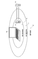
- FIG. 3 is a diagram showing the relationship between the position of the communication terminal 10 and the communication area
- FIG. 4 is a flowchart showing the flow of processing performed in the communication terminal 10.
- an area where the second communication by the TransferJet function can be performed is a second communication area X
- an area where the first communication by the FeliCa function is possible is a first communication area Y.
- An area where the first communication and the second communication are not possible is defined as an out-of-service area Z. 4 is started from a state where the communication terminal 10 is in the second communication region X of FIG.
- the located state detection unit 13 refers to the states of the first communication unit 11 and the second communication unit 12 to determine the personal computer for each of the first communication unit 11 and the second communication unit 12. It is acquired whether it is in the communication area which can communicate with 50, or it is out of the communication area which cannot communicate.
- step S12 the located state detection unit 13 determines whether or not the second communication is outside the communication range (communication establishment is impossible) and the first communication is within the communication range (communication establishment is possible).
- this condition is not satisfied (NO)
- the communication terminal 10 moves out of the second communication area X
- the condition of step S12 is satisfied (YES)
- the process proceeds to step S13. Note that when the communication terminal 10 moves out of the second communication area X, the second communication cannot be established, and the second communication unit 12 of the communication terminal 10 is disconnected.
- step S ⁇ b> 13 the communication state management unit 14 requests the first communication unit 11 to transition to a disconnected state or a standby state.
- the first communication unit 11 transitions to a disconnected state or a standby state in step S14.
- the communication terminal 10 moves outside the second communication area X having a short communication distance.
- the second communication unit 12 enters the disconnected state, and the first communication unit 11 also changes from the activated state to the disconnected state or the standby state. Therefore, even for the first communication unit 11 having a long communication distance, the first communication and the second communication cannot be performed in communication without waiting for the communication terminal 10 to move out of the first communication area Y. Since it changes to a disconnection state or a standby state at the time, the power consumption in the 1st communication part 11 can be suppressed.
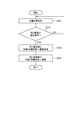
- FIG. 5 is a flowchart showing a flow of processing performed in the communication terminal 10. Note that the flowchart of FIG. 5 starts from a state in which the communication terminal 10 is in the out-of-service area Z of FIG.
- the located state detection unit 13 refers to the states of the first communication unit 11 and the second communication unit 12 to determine the personal computer for each of the first communication unit 11 and the second communication unit 12. It is acquired whether it is in the communication area which can communicate with 50, or it is out of the communication area which cannot communicate.
- step S22 the located state detection unit 13 determines whether or not the first communication is within the communication range (communication establishment is possible) and the second communication is outside the communication range (communication establishment is impossible).
- this condition is not satisfied (NO)
- the processes of steps S21 and S22 are repeated until step S22 is satisfied.
- the communication terminal 10 moves into the first communication area Y
- the condition of step S22 is satisfied (YES)
- the process proceeds to step S23. Note that when the communication terminal 10 moves into the first communication area Y, the first communication is in a communicable state, the first communication unit 11 of the communication terminal 10 is activated, and the first communication unit 11 and the personal computer 50 are connected. Communication with the first communication unit 51 is enabled.
- step S ⁇ b> 23 the communication state management unit 14 makes a request for transition to the activated state and a request for transition to the communication state with the second communication unit 52 of the personal computer 50 to the second communication unit 12.
- the second communication unit 12 receives a request from the communication state management unit 14, the second communication unit 12 transitions to an activated state in step S ⁇ b> 24 and enters a communication waiting state with the second communication unit 52 of the personal computer 50.
- the second communication unit 12 enters a communication state with the second communication unit 52 of the personal computer 50 in step S25. Transition.
- the communication terminal 10 when the user brings the communication terminal 10 close to the personal computer 50 with the intention of connecting the first communication and the second communication, the communication terminal 10 is in the first communication area Y having a long communication distance.
- the second communication unit 12 can be shifted to the activated state in advance. Thereby, when the communication terminal 10 moves into the 2nd communication area
- the other communication unit is changed to the activated state, the standby state, or the disconnected state based on the presence state of one of the first communication unit 11 and the second communication unit 12.
- the communication unit can be efficiently controlled, for example, the power consumption can be reduced and the communication unit can be quickly shifted to the communication state.
- the case where two communication interfaces are used has been described, but three or more may be used.
- communication using the FeliCa function and communication using the TransferJet function have been described as examples of the first communication and the second communication
- the type of communication function is not limited to this.
- Bluetooth can be used.
- the communication terminal according to the present invention is applied to a communication terminal having a voice call function, the communication terminal may be applied to other terminals.
- the personal computer 50 has been described as the other party that communicates with the communication terminal 10, but the present invention is not limited to this.
Abstract
Description
まず、通信端末10とパーソナルコンピュータ50とが非常に接近しており、第1通信および第2通信が行われている状態で、通信端末10をパーソナルコンピュータ50から引き離して通信を切断状態にする場合について、図3、4を用いて説明する。
次に、通信端末10をパーソナルコンピュータ50に徐々に近づけて、第1通信および第2通信を通信状態とする場合について、図3、5を用いて説明する。図5は、通信端末10で行われる処理の流れを示すフローチャートである。なお図5のフローチャートは、通信端末10が図3の圏外領域Z内にある状態から開始される。
Claims (4)
- 通信距離の異なる複数の通信手段を備えた通信端末において、
前記複数の通信手段のうち一の通信手段について、前記通信端末と通信を行う他の通信端末との距離が通信可能な通信圏内であるか、または通信不可能な通信圏外であるかを示す在圏状態を検出する在圏状態検出手段と、
前記在圏状態検出手段によって検出された在圏状態に応じて、他の通信手段を起動状態、待機状態または切断状態に遷移させる通信状態管理手段と、
を備えることを特徴とする通信端末。 - 前記通信状態管理手段は、前記複数の通信手段のうち最も通信距離が短い一の通信手段の在圏状態が、通信圏内から通信圏外に遷移したときに、他の通信手段を待機状態または切断状態に遷移させる、
ことを特徴とする請求項1に記載の通信端末。 - 前記通信状態管理手段は、前記複数の通信手段のうち最も通信距離が長い一の通信手段の在圏状態が、通信圏外から通信圏内に遷移したときに、他の通信手段を起動状態に遷移させる、
ことを特徴とする請求項1に記載の通信端末。 - 通信距離の異なる複数の通信手段を備えた通信端末の通信制御方法において、
前記複数の通信手段のうち一の通信手段について、前記通信端末と通信を行う他の通信端末との距離が通信可能な通信圏内であるか、または通信不可能な通信圏外であるかを示す在圏状態を検出する在圏状態検出ステップと、
前記在圏状態検出ステップによって検出された在圏状態に応じて、他の通信手段を起動状態、待機状態または切断状態に遷移させる通信状態管理ステップと、
を備えることを特徴とする通信制御方法。
Priority Applications (3)
| Application Number | Priority Date | Filing Date | Title |
|---|---|---|---|
| CN201080030366.3A CN102474905B (zh) | 2009-07-07 | 2010-06-30 | 通信终端以及通信控制方法 |
| US13/382,049 US8838032B2 (en) | 2009-07-07 | 2010-06-30 | Communication terminal and communication control method |
| EP10797056.8A EP2453713B1 (en) | 2009-07-07 | 2010-06-30 | Communication terminal and communication control method |
Applications Claiming Priority (2)
| Application Number | Priority Date | Filing Date | Title |
|---|---|---|---|
| JP2009-160894 | 2009-07-07 | ||
| JP2009160894A JP5165646B2 (ja) | 2009-07-07 | 2009-07-07 | 通信端末および通信制御方法 |
Publications (1)
| Publication Number | Publication Date |
|---|---|
| WO2011004745A1 true WO2011004745A1 (ja) | 2011-01-13 |
Family
ID=43429167
Family Applications (1)
| Application Number | Title | Priority Date | Filing Date |
|---|---|---|---|
| PCT/JP2010/061139 WO2011004745A1 (ja) | 2009-07-07 | 2010-06-30 | 通信端末および通信制御方法 |
Country Status (5)
| Country | Link |
|---|---|
| US (1) | US8838032B2 (ja) |
| EP (1) | EP2453713B1 (ja) |
| JP (1) | JP5165646B2 (ja) |
| CN (1) | CN102474905B (ja) |
| WO (1) | WO2011004745A1 (ja) |
Families Citing this family (13)
| Publication number | Priority date | Publication date | Assignee | Title |
|---|---|---|---|---|
| JP5727812B2 (ja) * | 2011-02-10 | 2015-06-03 | パナソニック株式会社 | 無線通信端末、無線通信装置及び無線通信方法 |
| JP5892653B2 (ja) | 2011-04-14 | 2016-03-23 | 株式会社カネカ | 高分子電解質およびその利用 |
| US10776103B2 (en) * | 2011-12-19 | 2020-09-15 | Majen Tech, LLC | System, method, and computer program product for coordination among multiple devices |
| JP5932543B2 (ja) * | 2012-07-26 | 2016-06-08 | 京セラ株式会社 | 通信端末,テザリング制御プログラムおよび方法ならびに通信システム |
| KR101976034B1 (ko) * | 2012-10-30 | 2019-05-09 | 에스케이플래닛 주식회사 | 근거리 통신을 이용한 테더링 제공 시스템 및 그 방법 |
| CN104580699B (zh) * | 2014-12-15 | 2017-06-30 | 广东欧珀移动通信有限公司 | 一种待机时声控智能终端方法及装置 |
| JP6520535B2 (ja) * | 2015-08-03 | 2019-05-29 | 富士通株式会社 | 情報配信方法、情報配信プログラムおよび情報配信装置 |
| CN109328308B (zh) * | 2016-07-21 | 2023-09-01 | 三菱电机楼宇解决方案株式会社 | 位置计测系统和便携终端装置 |
| CN106375566A (zh) * | 2016-08-31 | 2017-02-01 | 珠海格力电器股份有限公司 | 一种手机的使用方法、装置及终端 |
| SE541883C2 (en) * | 2017-11-21 | 2020-01-02 | Crunchfish Proximity Ab C/O Crunchfish Ab | Early activation of mobile device to enable use at service terminal |
| SE541886C2 (en) * | 2018-03-09 | 2020-01-02 | Crunchfish Proximity Ab C/O Crunchfish Ab | Method, system and devices for causing proximity-dependent activity by a mobile device |
| WO2020112010A1 (en) * | 2018-11-26 | 2020-06-04 | Crunchfish Proximity Ab | Triggering a proximity-based digital action with a mobile device and a base device |
| SE543574C2 (en) * | 2018-11-26 | 2021-03-30 | Crunchfish Proximity Ab C/O Crunchfish Ab | Triggering a proximity-based digital action with a mobile device and a base device |
Citations (4)
| Publication number | Priority date | Publication date | Assignee | Title |
|---|---|---|---|---|
| JP2003032176A (ja) | 2001-07-18 | 2003-01-31 | Sony Corp | 通信システムおよび方法、情報処理装置および方法、通信端末および方法、拡張装置、並びにプログラム |
| WO2005094046A1 (ja) * | 2004-03-29 | 2005-10-06 | Pioneer Corporation | 無線通信システム、固定情報装置、携帯端末装置 |
| JP2008066781A (ja) * | 2006-09-04 | 2008-03-21 | Toshiba Corp | 携帯無線端末 |
| JP2009135610A (ja) * | 2007-11-28 | 2009-06-18 | Sony Corp | 通信システム並びに通信装置 |
Family Cites Families (1)
| Publication number | Priority date | Publication date | Assignee | Title |
|---|---|---|---|---|
| US20040259544A1 (en) * | 2003-06-20 | 2004-12-23 | Amos James A. | Hybrid wireless IP phone system and method for using the same |
-
2009
- 2009-07-07 JP JP2009160894A patent/JP5165646B2/ja active Active
-
2010
- 2010-06-30 US US13/382,049 patent/US8838032B2/en active Active
- 2010-06-30 CN CN201080030366.3A patent/CN102474905B/zh not_active Expired - Fee Related
- 2010-06-30 EP EP10797056.8A patent/EP2453713B1/en active Active
- 2010-06-30 WO PCT/JP2010/061139 patent/WO2011004745A1/ja active Application Filing
Patent Citations (4)
| Publication number | Priority date | Publication date | Assignee | Title |
|---|---|---|---|---|
| JP2003032176A (ja) | 2001-07-18 | 2003-01-31 | Sony Corp | 通信システムおよび方法、情報処理装置および方法、通信端末および方法、拡張装置、並びにプログラム |
| WO2005094046A1 (ja) * | 2004-03-29 | 2005-10-06 | Pioneer Corporation | 無線通信システム、固定情報装置、携帯端末装置 |
| JP2008066781A (ja) * | 2006-09-04 | 2008-03-21 | Toshiba Corp | 携帯無線端末 |
| JP2009135610A (ja) * | 2007-11-28 | 2009-06-18 | Sony Corp | 通信システム並びに通信装置 |
Non-Patent Citations (1)
| Title |
|---|
| See also references of EP2453713A4 |
Also Published As
| Publication number | Publication date |
|---|---|
| JP5165646B2 (ja) | 2013-03-21 |
| CN102474905A (zh) | 2012-05-23 |
| CN102474905B (zh) | 2014-07-02 |
| EP2453713A4 (en) | 2014-11-05 |
| US8838032B2 (en) | 2014-09-16 |
| US20120129454A1 (en) | 2012-05-24 |
| EP2453713B1 (en) | 2016-08-10 |
| JP2011018990A (ja) | 2011-01-27 |
| EP2453713A1 (en) | 2012-05-16 |
Similar Documents
| Publication | Publication Date | Title |
|---|---|---|
| JP5165646B2 (ja) | 通信端末および通信制御方法 | |
| JP4534904B2 (ja) | ブルートゥース無線機、近距離無線通信機およびプログラム | |
| CN107889092B (zh) | 蓝牙设备通信控制方法、装置、终端设备及存储介质 | |
| CN108419226B (zh) | 一种蓝牙设备之间连接的方法及蓝牙设备 | |
| US8620216B2 (en) | System and method for automatically switching connection of a wireless interface | |
| CN102342174B (zh) | 车载终端装置和用于车载终端装置的无线连接程序 | |
| US20040198425A1 (en) | Establishing half-duplex audio link as battery saving means | |
| JP4599449B2 (ja) | 電子機器及び通信制御方法 | |
| US20080051156A1 (en) | Hands-free apparatus | |
| JP2013013011A (ja) | 近距離無線通信装置 | |
| JP2011182110A (ja) | 電子機器及び通信制御方法 | |
| EP2747395B1 (en) | Mobile terminal and power saving method thereof | |
| US9258672B2 (en) | Short-range wireless communication device | |
| JP2008011416A (ja) | 情報処理装置および制御方法 | |
| US7970352B2 (en) | Wireless communication device | |
| JP5119215B2 (ja) | 通信端末および通信制御方法 | |
| KR20100070875A (ko) | 재연결 가능한 블루투스 장치 및 그 방법 | |
| US20120094602A1 (en) | Bluetooth headset for mobile phone | |
| JP5398800B2 (ja) | 電子機器及び通信制御方法 | |
| JP5407770B2 (ja) | 通信端末装置、通信制御方法及び通信制御プログラム | |
| JP5010718B2 (ja) | 通信装置および通信制御方法 | |
| JP2014082563A (ja) | 無線通信システムおよび無線通信の電力削減方法 | |
| JPH11331183A (ja) | 移動体無線通信システム | |
| KR20050000671A (ko) | 소비 전류를 줄이기 위한 블루투스 모듈이 구비된 휴대용단말기 간의 인터콤 연결 방법 |
Legal Events
| Date | Code | Title | Description |
|---|---|---|---|
| WWE | Wipo information: entry into national phase |
Ref document number: 201080030366.3 Country of ref document: CN |
|
| 121 | Ep: the epo has been informed by wipo that ep was designated in this application |
Ref document number: 10797056 Country of ref document: EP Kind code of ref document: A1 |
|
| REEP | Request for entry into the european phase |
Ref document number: 2010797056 Country of ref document: EP |
|
| WWE | Wipo information: entry into national phase |
Ref document number: 2010797056 Country of ref document: EP |
|
| NENP | Non-entry into the national phase |
Ref country code: DE |
|
| WWE | Wipo information: entry into national phase |
Ref document number: 13382049 Country of ref document: US |