WO2011004628A1 - 長尺積層フィルムの製造方法 - Google Patents
長尺積層フィルムの製造方法 Download PDFInfo
- Publication number
- WO2011004628A1 WO2011004628A1 PCT/JP2010/052820 JP2010052820W WO2011004628A1 WO 2011004628 A1 WO2011004628 A1 WO 2011004628A1 JP 2010052820 W JP2010052820 W JP 2010052820W WO 2011004628 A1 WO2011004628 A1 WO 2011004628A1
- Authority
- WO
- WIPO (PCT)
- Prior art keywords
- guide roll
- long film
- long
- film
- roll
- Prior art date
- Legal status (The legal status is an assumption and is not a legal conclusion. Google has not performed a legal analysis and makes no representation as to the accuracy of the status listed.)
- Ceased
Links
Images


Classifications
-
- B—PERFORMING OPERATIONS; TRANSPORTING
- B05—SPRAYING OR ATOMISING IN GENERAL; APPLYING FLUENT MATERIALS TO SURFACES, IN GENERAL
- B05D—PROCESSES FOR APPLYING FLUENT MATERIALS TO SURFACES, IN GENERAL
- B05D1/00—Processes for applying liquids or other fluent materials
- B05D1/26—Processes for applying liquids or other fluent materials performed by applying the liquid or other fluent material from an outlet device in contact with, or almost in contact with, the surface
- B05D1/265—Extrusion coatings
-
- B—PERFORMING OPERATIONS; TRANSPORTING
- B05—SPRAYING OR ATOMISING IN GENERAL; APPLYING FLUENT MATERIALS TO SURFACES, IN GENERAL
- B05C—APPARATUS FOR APPLYING FLUENT MATERIALS TO SURFACES, IN GENERAL
- B05C5/00—Apparatus in which liquid or other fluent material is projected, poured or allowed to flow on to the surface of the work
- B05C5/02—Apparatus in which liquid or other fluent material is projected, poured or allowed to flow on to the surface of the work the liquid or other fluent material being discharged through an outlet orifice by pressure, e.g. from an outlet device in contact or almost in contact, with the work
- B05C5/0254—Coating heads with slot-shaped outlet
-
- B—PERFORMING OPERATIONS; TRANSPORTING
- B05—SPRAYING OR ATOMISING IN GENERAL; APPLYING FLUENT MATERIALS TO SURFACES, IN GENERAL
- B05D—PROCESSES FOR APPLYING FLUENT MATERIALS TO SURFACES, IN GENERAL
- B05D2252/00—Sheets
- B05D2252/02—Sheets of indefinite length
Definitions
- the present invention relates to a method for producing a long laminated film in which a coating layer is laminated on a long film.
- the following method is known as a method for producing a long laminated film in which a coating layer is laminated on a long film.
- the long film 31 is run while being supported by the two guide rolls 32 and 33.
- the coating head 34 is pressed against the surface 31 a of the long film 31 to apply the coating 35, thereby forming the coating layer 36.
- the coating head 34 is between the two guide rolls 32 and 33 (for example, Patent Document 1).
- striped unevenness may occur in the coating layer 36.
- the long film 31 is run while being supported by the two guide rolls 32 and 33.
- the coating head 34 is pressed against the surface 31 a of the long film 31, the coating 35 is applied, the coating layer 36 is formed, and the long laminated film 37 is manufactured.
- striped unevenness may occur in the coating layer 36.
- the present invention provides a method for producing a long laminated film in which striped unevenness, which has been a problem in the past, does not occur.
- the gist of the present invention is as follows.
- This invention is a manufacturing method of the elongate laminated film which laminated
- the back surface of the long film is supported by the first guide roll and the second guide roll.
- the second guide roll is disposed downstream of the first guide roll in the traveling direction.
- a pair of nip rolls are provided at positions facing the first guide roll or the second guide roll.
- the pair of nip rolls are arranged in a square shape so that the respective rotation axes intersect on the downstream side in the traveling direction.
- an application head is pressed against the surface of the long film, and a paint is applied to form an application layer.
- the angle between the rotation axis of the nip roll and the rotation axis of the first guide roll or the second guide roll is 1 ° to 10 °.
- a nip roll contacts a long film and a 1st guide roll or a 2nd guide roll simultaneously.
- the outer peripheral surface of a nip roll is elastomer resin.
- wrinkles of the long film 31 occur because a difference occurs in the amount of contraction in the width direction between the portion in contact with the two guide rolls 32 and 33 and between the two guide rolls 32 and 33.
- the paint 35 is applied on the long film 31 while the long film 31 is wrinkled. For this reason, the coating material 35 flows into the concave portion of the wrinkle, the coating thickness is increased, and the thickness of the coating layer 36 varies. This was a cause of striped unevenness generated in the coating layer 36.
- the long film is caused to travel while sandwiching both ends in the width direction of the long film between the pair of nip rolls and the second guide roll (or the first guide roll). I made it.
- the pair of nip rolls are arranged in a square shape, and each rotation axis intersects on the downstream side in the running direction of the long film.
- a long laminated film having a coating layer having a uniform thickness can be obtained. Thereby, generation
- Schematic diagram of the production method of the present invention Schematic diagram of nip roll and guide roll used in the production method of the present invention Schematic diagram of a long laminated film obtained by the production method of the present invention
- A Photo of long laminated film obtained by the production method of the present invention
- b Photo of long laminated film obtained by the conventional production method
- the manufacturing method of this invention is a manufacturing method of the elongate laminated film which laminated
- the manufacturing method of the present invention has the following characteristics. The manufacturing method of the present invention will be described with reference to FIG.
- the back surface 11 b of the long film 11 is supported by the first guide roll 12 and the second guide roll 13.
- the surface to which the paint 14 is applied is the front surface 11a of the long film 11, and the surface to which the paint 14 is not applied is the back surface 11b.
- an upstream guide roll is a first guide roll 12, and a downstream guide roll is a second guide roll 13.
- the long film 11 is caused to travel while sandwiching both ends 11c in the width direction of the long film 11 between the pair of nip rolls 16 and 17 and the second guide roll 13.
- the pair of nip rolls 16 and 17 are arranged in a square shape, and the respective rotation shafts 16 a and 17 a intersect at an intersection 18 on the downstream side in the traveling direction 15 of the long film 11.
- the rotational peripheral speeds of the nip rolls 16 and 17 and the second guide roll 13 are equal, the rotation axes 16 a and 17 a of the nip rolls 16 and 17 are not orthogonal to the traveling direction 15, so that the long film 11 has a traveling direction 15.
- a force 19 in the width direction is also applied.
- the force 19 in the width direction works to increase the width of the long film 11. By applying the force 19 in the width direction, the wrinkles of the long film 11 are eliminated.
- the coating layer 14 is formed by applying the coating 14 while pressing the coating head 20 against the surface 11 a of the long film 11. .
- the finished laminate of the long film 11 and the coating layer 21 is a long laminated film 22.
- the manufacturing method of the present invention may add other steps in addition to the above (1) to (3).
- steps include a step of hydrophilizing the long film (eg, corona treatment), a step of aligning the long film (eg, rubbing), and a step of drying the coating layer.
- the long film 11 used in the present invention is a film whose length is sufficiently larger than its width.
- the length is preferably at least 10 times the width.
- the length of the long film 11 is preferably 300 m or more.
- the thickness of the long film 11 is preferably 5 ⁇ m to 200 ⁇ m. According to the present invention, it is possible to use a thin long film 11 having a thickness of about 5 ⁇ m to 50 ⁇ m, which has been difficult to use because it is easy to cause wrinkles.
- the long film 11 is preferably transparent.
- the transmittance at a wavelength of 590 nm is preferably 80% or more.
- the material for forming the long film 11 is not particularly limited, and examples thereof include polyester resins, cellulose resins, cycloolefin resins, and acrylic resins.
- the long film 11 may be a single layer film or a multilayer film in which a polymer film such as polyimide or polyvinyl alcohol is coated on a single layer film.
- the tension in the running direction 15 applied to the long film 11 is preferably 50 N to 200 N per 1 m of film width in order to stabilize running.
- the first guide roll 12 and the second guide roll 13 used in the present invention support the back surface 11 b of the long film 11 when the long film 11 travels.
- the second guide roll 13 is further downstream in the traveling direction 15 than the first guide roll 12.
- the diameters of the first guide roll 12 and the second guide roll 13 are usually 20 mm to 40 mm.
- the material of the first guide roll 12 and the second guide roll 13 is, for example, aluminum, iron, stainless steel, carbon composite material, rubber, nickel, chromium, or the like.
- the inter-axis distance between the first guide roll 12 and the second guide roll 13 is appropriately determined depending on the size of the coating head 20 and the diameters of the first guide roll 12 and the second guide roll 13, but preferably 20 mm to 1,000 mm.
- the first guide roll 12 and the second guide roll 13 may be a drive roll connected to a drive source, or may be a free roll that rotates passively as the long film 11 travels.
- the pair of nip rolls 16 and 17 used in the present invention is used to run the long film 11 while sandwiching both end portions 11 c in the width direction of the long film 11 between the second guide roll 13. .
- the pair of nip rolls 16 and 17 are arranged in a square shape, and the respective rotation shafts 16 a and 17 a intersect at an intersection 18 on the downstream side in the running direction 15 of the long film 11.
- the rotating shafts 16a and 17a of the nip rolls 16 and 17 are not orthogonal to the traveling direction 15, so the long film 11 has a traveling direction.
- a force 19 in the width direction is also applied.
- the force 19 in the width direction is a force in the direction of increasing the width of the long film 11.
- the positional relationship between the nip rolls 16 and 17 and the second guide roll 13 is shown in FIG.
- the angle ⁇ between the rotating shaft 16a of the nip roll 16 and the rotating shaft 13a of the second guide roll 13 is preferably 1 ° to 10 ° from the viewpoint of effectively suppressing wrinkles. The same applies to the nip roll 17.
- the diameter d of the nip rolls 16 and 17 is usually 10 mm to 50 mm. As shown in FIG. 1, the nip rolls 16 and 17 are preferably in contact with both the long film 11 and the second guide roll 13 at the same time. From this viewpoint, the width w of the nip rolls 16 and 17 needs to be somewhat wide, and is preferably 10 mm to 50 mm.
- the outer peripheral surface of the nip rolls 16 and 17 (the surface where the nip rolls 16 and 17 are in contact with the long film 11 and the second guide roll 13) is not particularly limited, but is an elastomer resin such as styrene rubber or urethane rubber. Is preferred.
- nip rolls 16 and 17 may be provided at positions facing the first guide roll 12.
- the coating head 20 used in the present invention applies the coating 14 to the surface 11 a of the long film 11 while being pressed against the long film 11 to form the coating layer 21.
- the coating head 20 is not particularly limited as long as the coating layer 21 can be formed, and a gravure head, a die head, a wire bar, or the like is used.
- the viscosity of the coating material 14 used in the present invention is preferably 50 mPa ⁇ s to 5,000 mPa ⁇ s at a shear rate of 100 s ⁇ 1 with a rotary viscometer.
- a paint 14 having a low viscosity for example, 50 mPa ⁇ s or less, which has conventionally been easy to flow against wrinkles and is difficult to use.
- the pressing amount of the coating head 20 is preferably more than 0 mm and not more than 50 mm based on the position of the long film 11 in a state where the coating head 20 is not pushed.
- the coating layer obtained by the production method of the present invention is not particularly limited, but is preferably a solution or dispersion containing a liquid crystal compound and a solvent developed on a long film surface in layers.
- the wet thickness of the coating layer is preferably 1 ⁇ m to 10 ⁇ m.
- a coating layer containing a liquid crystal compound must be thin and uniform in order to obtain practical optical properties.
- it is necessary to make the paint have a low viscosity.
- low-viscosity paints are susceptible to the adverse effects of long film wrinkles. Therefore, it has been difficult to form a uniform coating layer with the conventional manufacturing method.
- the content of the liquid crystal compound is preferably 0.1% by weight to 10% by weight with respect to the total weight of the coating layer.
- liquid crystal compound examples include azo compounds, anthraquinone compounds, perylene compounds, quinophthalone compounds, naphthoquinone compounds, merocyanine compounds, and the like.
- azo compounds anthraquinone compounds
- perylene compounds examples include quinophthalone compounds, naphthoquinone compounds, merocyanine compounds, and the like.
- Such a liquid crystal compound exhibits absorption dichroism in the visible light region (wavelength 380 nm to 780 nm). Therefore, the coating layer containing such a liquid crystal compound can be used as a polarizer.
- the long laminated film 22 obtained by the manufacturing method of the present invention includes the long film 11 and a coating layer 21 formed on the surface thereof.
- the total thickness of the long laminated film 22 is preferably 10 ⁇ m to 300 ⁇ m.
- This monoazo compound is similarly diazotized by a conventional method, and further subjected to a coupling reaction with 1-amino-8-naphthol-2,4-disulfonic acid lithium salt to produce a crude product containing an azo compound of the following structural formula (1) I got a thing. This was salted out with lithium chloride to obtain an azo compound of the following structural formula (1).
- a rubbing treatment and a corona treatment were performed on the surface of a long film containing a cycloolefin resin (ZEONOR manufactured by Nippon Zeon Co., Ltd., thickness 40 ⁇ m).
- aqueous solution containing the above azo compound was applied to the corona-treated surface of the long film using the coating means shown in FIG. 1 to form a coating layer.
- concentration of the azo compound was 18% by weight with respect to the total weight of the aqueous solution.
- the viscosity of the aqueous solution containing the azo compound was 60 mPa ⁇ s at a shear rate of 100 s ⁇ 1 as measured by a rotary viscometer (RS1 manufactured by HAKKE).
- the long laminated film was placed in a constant temperature oven at 40 ° C., moisture was removed from the coating layer, and a solidified layer having a thickness of 0.4 ⁇ m was formed on the surface of the long film.
- the long laminated film which consists of a laminated body of a long film and a solidified layer was obtained.
- the obtained long laminated film exhibited absorption dichroism in the visible light region, and no striped unevenness was observed on the surface of the solidified layer (FIG. 4 (a)).
- a commercially available polarizing plate (NPF-SEG1224DU manufactured by Nitto Denko Corporation) is placed on a backlight (flat illuminator manufactured by Dentsu Sangyo Co., Ltd.) having a luminance of 10,000 cd / m 2 , and the produced optical laminated film is absorbed on the polarizing plate. It arrange
- the use of the long laminated film obtained by the production method of the present invention is not particularly limited.
- the coating layer exhibits absorption dichroism in the visible light region, it is suitable for use as a polarizing plate.
Landscapes
- Application Of Or Painting With Fluid Materials (AREA)
Abstract
従来は、長尺フィルムを2本のガイドロールで支持して走行させながら、長尺フィルムの表面に塗布ヘッドを押し付けて、塗料を塗布し、塗布層を形成した。その場合、塗布層に縞状のムラが生じることがある。そこで、本願発明では、一対のニップロール(16)、(17)と第二のガイドロール(13)との間に、長尺フィルム(11)の幅方向両端部(11c)を挟みながら、長尺フィルム(11)を走行させる。一対のニップロール(16)、(17)はハの字形に配置され、各々の回転軸(16a)、(17a)が長尺フィルム(11)の走行方向(15)の下流側の交点(18)で交差する。長尺フィルム(11)には、走行方向(15)の力だけでなく、幅方向の力(19)も加わる。幅方向の力(19)は、長尺フィルム(11)の幅を広げる。幅方向の力(19)が加わることにより、長尺フィルム(11)のシワが解消される。
Description
本発明は、長尺フィルムに塗布層を積層した長尺積層フィルムの製造方法に関する。
長尺フィルムに塗布層を積層した長尺積層フィルムの製造方法として、従来、次の方法が知られている。図5に示すように、長尺フィルム31を、2本のガイドロール32、33で支持しながら走行させる。長尺フィルム31の表面31aに、塗布ヘッド34を押し付けて塗料35を塗布し、塗布層36を形成する。塗布ヘッド34は、2本のガイドロール32、33の間にある(例えば、特許文献1)。しかし、従来の製造方法では、塗布層36に縞状のムラが生じることがあった。
従来の製造方法では、長尺フィルム31を、2本のガイドロール32、33で支持しながら走行させる。長尺フィルム31の表面31aに塗布ヘッド34を押し付けて、塗料35を塗布し、塗布層36を形成して、長尺積層フィルム37を製造する。しかし、従来の製造方法においては、塗布層36に縞状のムラが生じることがある。
本発明は、従来問題となっていた縞状のムラが生じない、長尺積層フィルムの製造方法を提供する。
本発明の要旨は以下の通りである。
(1)本発明は、長尺フィルムに塗布層を積層した長尺積層フィルムの製造方法である。本発明の製造方法においては、長尺フィルムの裏面を、第一のガイドロールと第二のガイドロールにより支持する。第二のガイドロールは、第一のガイドロールよりも走行方向の下流に配置される。一対のニップロールが、第一のガイドロールまたは第二のガイドロールと対向する位置に設けられる。一対のニップロールは、それぞれの回転軸が走行方向の下流側で交差するように、ハの字形に配置される。一対のニップロールと、第一のガイドロールまたは第二のガイドロールとの間に、長尺フィルムの幅方向の両端部を挟み、長尺フィルムに幅を広げる方向の力を与えながら、長尺フィルムを走行させる。第一のガイドロールと第二のガイドロールとの間で、長尺フィルムの表面に塗布ヘッドを押し付け、塗料を塗布して、塗布層を形成する。
(2)本発明の製造方法においては、ニップロールの回転軸と、第一のガイドロールまたは第二のガイドロールの回転軸との交わる角度が、1°~10°である。
(3)本発明の製造方法においては、ニップロールが、長尺フィルムと、第一のガイドロールまたは第二のガイドロールとに、同時に接する。
(4)本発明の製造方法においては、ニップロールの外周面が、エラストマー樹脂である。
(1)本発明は、長尺フィルムに塗布層を積層した長尺積層フィルムの製造方法である。本発明の製造方法においては、長尺フィルムの裏面を、第一のガイドロールと第二のガイドロールにより支持する。第二のガイドロールは、第一のガイドロールよりも走行方向の下流に配置される。一対のニップロールが、第一のガイドロールまたは第二のガイドロールと対向する位置に設けられる。一対のニップロールは、それぞれの回転軸が走行方向の下流側で交差するように、ハの字形に配置される。一対のニップロールと、第一のガイドロールまたは第二のガイドロールとの間に、長尺フィルムの幅方向の両端部を挟み、長尺フィルムに幅を広げる方向の力を与えながら、長尺フィルムを走行させる。第一のガイドロールと第二のガイドロールとの間で、長尺フィルムの表面に塗布ヘッドを押し付け、塗料を塗布して、塗布層を形成する。
(2)本発明の製造方法においては、ニップロールの回転軸と、第一のガイドロールまたは第二のガイドロールの回転軸との交わる角度が、1°~10°である。
(3)本発明の製造方法においては、ニップロールが、長尺フィルムと、第一のガイドロールまたは第二のガイドロールとに、同時に接する。
(4)本発明の製造方法においては、ニップロールの外周面が、エラストマー樹脂である。
本発明者らは、上記課題を解決すべく鋭意検討した結果、塗布層36に生じる縞状のムラが、次のようにして発生することを発見した。
通常、長尺フィルム31を安定して搬送するためには、長尺フィルム31に走行方向38の張力を付与する必要がある。長尺フィルム31の、ガイドロール32、33と接している部分は、ガイドロール32、33との摩擦があるため、長尺フィルム31の幅が縮みにくい。一方、2本のガイドロール32、33の間の長尺フィルム31は、幅方向の規制が無いため、走行方向38の張力により、幅が縮みやすい。
2本のガイドロール32、33に接した部分と、2本のガイドロール32、33の間とで幅方向の収縮量に差が生じるため、長尺フィルム31のシワが生じると考えられる。
従来の製造方法においては、長尺フィルム31にシワがある状態で、長尺フィルム31上に塗料35が塗布される。このため、シワの凹部へ塗料35が流れて塗布厚みが厚くなり、塗布層36の厚みにバラツキが生じる。これが、塗布層36に生じる縞状のムラの原因となっていた。
そこで、本発明においては、一対のニップロールと第二のガイドロール(または、第一のガイドロール)との間に、長尺フィルムの幅方向の両端部を挟みながら、長尺フィルムを走行させるようにした。一対のニップロールはハの字形に配置され、各々の回転軸が長尺フィルムの走行方向の下流側で交差する。
このようにすると、走行中の長尺フィルムに、幅を広げる方向の力を加えることができる。それにより、第二のガイドロールの上流側で発生していたシワが、第二のガイドロールとニップロールの間を通過するときに解消される。その結果、長尺フィルムのシワがほとんど発生しなくなる。この状態で、長尺フィルムに塗料を塗布すると、厚みにバラツキの無い塗布層が得られ、問題となるような縞状のムラは発生しなくなる。
本発明の製造方法により、均一な厚みの塗布層をもつ長尺積層フィルムが得られる。これにより、縞状のムラなどの発生が避けられる。本発明の製造方法では、従来、シワが生じやすく、使用することが難しかった、厚み5μm~50μm程度の薄い長尺フィルムでも使用できる。また、本発明の製造方法では、従来、シワの凹凸に対して流動しやすく、使用が難しかった、粘度の低い(例えば50mPa・s以下の)塗料でも使用できる。
[本発明の製造方法]
本発明の製造方法は、長尺フィルムに塗布層を積層した長尺積層フィルムの製造方法である。本発明の製造方法は、次の特徴を有する。図1を参照して、本発明の製造方法を説明する。
本発明の製造方法は、長尺フィルムに塗布層を積層した長尺積層フィルムの製造方法である。本発明の製造方法は、次の特徴を有する。図1を参照して、本発明の製造方法を説明する。
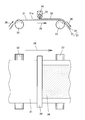
(1)長尺フィルム11の裏面11bを、第一のガイドロール12と第二のガイドロール13とで支持する。塗料14を塗布する面を、長尺フィルム11の表面11a、塗料14を塗布しない面を、裏面11bとする。長尺フィルム11の走行方向15の、上流のガイドロールを第一のガイドロール12、下流のガイドロールを第二のガイドロール13とする。
(2)一対のニップロール16、17と第二のガイドロール13との間に、長尺フィルム11の幅方向両端部11cを挟みながら、長尺フィルム11を走行させる。一対のニップロール16、17はハの字形に配置され、各々の回転軸16a、17aが、長尺フィルム11の走行方向15の、下流側の交点18で交差する。ニップロール16、17と第二のガイドロール13の回転周速度は等しいが、ニップロール16、17の回転軸16a、17aが、走行方向15と直交していないため、長尺フィルム11には走行方向15の力だけでなく、幅方向の力19も加わる。幅方向の力19は、長尺フィルム11の幅を広げるように働く。幅方向の力19が加わることにより、長尺フィルム11のシワが解消される。
(3)第一のガイドロール12と第二のガイドロール13との間で、長尺フィルム11の表面11aに、塗布ヘッド20を押し付けながら、塗料14を塗布して、塗布層21を形成する。出来上がった、長尺フィルム11と塗布層21の積層体が、長尺積層フィルム22である。
本発明の製造方法は、上記(1)~(3)に加えて、他の工程を付加してもよい。他の工程としては、例えば、長尺フィルムを親水化処理(例、コロナ処理)する工程、長尺フィルムを配向処理(例、ラビング処理)する工程、塗布層を乾燥させる工程などがある。
[長尺フィルム]
本発明に用いられる長尺フィルム11は、長さが幅より十分に大きいフィルムである。長さは、好ましくは、幅の10倍以上である。長尺フィルム11の長さは、好ましくは、300m以上である。
本発明に用いられる長尺フィルム11は、長さが幅より十分に大きいフィルムである。長さは、好ましくは、幅の10倍以上である。長尺フィルム11の長さは、好ましくは、300m以上である。
長尺フィルム11の厚みは、好ましくは、5μm~200μmである。本発明によれば、従来、シワが生じやすく使用することが難しかった、厚み5μm~50μm程度の薄い長尺フィルム11でも使用できる。
長尺フィルム11は透明であるものが好ましい。例えば、波長590nm(黄色~橙色)での透過率が、80%以上のものが好ましい。
長尺フィルム11を形成する材料は、特に制限はないが、例えば、ポリエステル系樹脂、セルロース系樹脂、シクロオレフィン系樹脂、アクリル系樹脂などが挙げられる。
長尺フィルム11は、単層フィルムでもよいし、単層フィルム上に、ポリイミドやポリビニルアルコールなどの高分子膜が塗布された複層フィルムでもよい。
長尺フィルム11に付与する走行方向15の張力は、走行を安定させるため、フィルム幅1mあたり、50N~200Nであることが好ましい。
[ガイドロール]
本発明に用いられる第一のガイドロール12および第二のガイドロール13は、長尺フィルム11の走行時に、長尺フィルム11の裏面11bを支持する。第二のガイドロール13は、第一のガイドロール12よりも、走行方向15の下流にある。
本発明に用いられる第一のガイドロール12および第二のガイドロール13は、長尺フィルム11の走行時に、長尺フィルム11の裏面11bを支持する。第二のガイドロール13は、第一のガイドロール12よりも、走行方向15の下流にある。
第一のガイドロール12および第二のガイドロール13の直径は、通常20mm~40mmである。第一のガイドロール12および第二のガイドロール13の材料は、例えば、アルミニウム、鉄、ステンレス、炭素複合材、ゴム、ニッケル、クロムなどである。
第一のガイドロール12と第二のガイドロール13との軸間距離は、塗布ヘッド20の大きさや第一のガイドロール12および第二のガイドロール13の直径によって適宜決定されるが、好ましくは、20mm~1,000mmである。
第一のガイドロール12と第二のガイドロール13は、駆動源に接続された駆動ロールでもよいし、長尺フィルム11の走行に伴って受動的に回転する、フリーロールでもよい。
[ニップロール]
本発明に用いられる一対のニップロール16、17は、第二のガイドロール13との間に、長尺フィルム11の幅方向の両端部11cを挟みながら、長尺フィルム11を走行させるのに用いられる。一対のニップロール16、17はハの字形に配置され、各々の回転軸16a、17aが、長尺フィルム11の走行方向15の下流側の交点18で交差する。
本発明に用いられる一対のニップロール16、17は、第二のガイドロール13との間に、長尺フィルム11の幅方向の両端部11cを挟みながら、長尺フィルム11を走行させるのに用いられる。一対のニップロール16、17はハの字形に配置され、各々の回転軸16a、17aが、長尺フィルム11の走行方向15の下流側の交点18で交差する。
ニップロール16、17と第二のガイドロール13の回転周速度は等しいが、ニップロール16、17の回転軸16a、17aが、走行方向15と直交していないため、長尺フィルム11には、走行方向15の力だけでなく、幅方向の力19も加わる。幅方向の力19は、長尺フィルム11の幅を広げる方向の力である。
走行中の長尺フィルム11に、幅方向の力19が加わるので、第二のガイドロール13の上流側で発生していたシワが、第二のガイドロール13とニップロール16、17の間を通過するときに解消される。その結果、長尺フィルム11のシワがほとんど発生しなくなる。この状態で、長尺フィルム11に塗料14を塗布すると、厚みにバラツキの無い塗布層21が得られ、縞状のムラが見られなくなる。
ニップロール16、17と第二のガイドロール13との位置関係を、図2に示す。ニップロール16の回転軸16aと、第二のガイドロール13の回転軸13aの交わる角度θは、シワを効果的に抑制する観点から、1°~10°が好ましい。ニップロール17についても同様である。
ニップロール16、17の直径dは、通常10mm~50mmである。ニップロール16、17は、図1に示すように、長尺フィルム11と第二のガイドロール13の両方に、同時に接することが好ましい。その観点から、ニップロール16、17の幅wはある程度広い必要があり、好ましくは、10mm~50mmである。
ニップロール16、17の外周面(ニップロール16、17が、長尺フィルム11および第二のガイドロール13と接する面)は、特に制限はないが、スチレンゴムやウレタンゴムのようなエラストマー樹脂であることが好ましい。
図示しないが、ニップロール16、17は、第一のガイドロール12に対向する位置に設けてもよい。
[塗布ヘッド]
本発明に用いられる塗布ヘッド20は、長尺フィルム11に押し付けられながら、長尺フィルム11の表面11aに塗料14を塗布して、塗布層21を形成する。
本発明に用いられる塗布ヘッド20は、長尺フィルム11に押し付けられながら、長尺フィルム11の表面11aに塗料14を塗布して、塗布層21を形成する。
塗布ヘッド20は、塗布層21を形成できるものであれば、特に制限はなく、グラビアヘッド、ダイヘッド、ワイヤーバーなどが用いられる。
本発明に用いられる塗料14の粘度は、回転式粘度計で、剪断速度100s-1における測定粘度が、好ましくは、50mPa・s~5,000mPa・sである。
本発明によれば、従来、シワの凹凸に対して流動しやすく、使用が難しかった、粘度の低い(例えば50mPa・s以下の)塗料14も使用できる。
塗布ヘッド20の押し込み量は、塗布ヘッド20を押し込まない状態の長尺フィルム11の位置を基準にして、0mmを超え、50mm以下が好ましい。
[塗布層]
本発明の製造方法により得られる塗布層は、特に制限はないが、好ましくは、液晶化合物と溶媒とを含む溶液または分散液を、長尺フィルム表面に、層状に展開したものである。塗布層のウェット厚みは、好ましくは、1μm~10μmである。
本発明の製造方法により得られる塗布層は、特に制限はないが、好ましくは、液晶化合物と溶媒とを含む溶液または分散液を、長尺フィルム表面に、層状に展開したものである。塗布層のウェット厚みは、好ましくは、1μm~10μmである。
一般に、液晶化合物を含む塗布層は、実用的な光学特性を得るため、薄く均一でなければならない。そのためには、塗料を低粘度にする必要がある。しかし、低粘度の塗料は、長尺フィルムのシワの悪影響を受けやすい。そのため従来の製造方法では、均一な塗布層を形成することが困難であった。
本発明の製造方法によれば、長尺フィルムのシワが効果的に抑制できるため、低粘度の塗料を薄く均一に塗布することができる。それによって、薄く均一な塗布層が得られる。
塗布層が液晶化合物を含む場合、液晶化合物の含有量は、塗布層の総重量に対して、好ましくは、0.1重量%~10重量%である。
液晶化合物としては、例えば、アゾ系化合物、アントラキノン系化合物、ペリレン系化合物、キノフタロン系化合物、ナフトキノン系化合物、メロシアニン系化合物などが挙げられる。このような液晶化合物は、可視光領域(波長380nm~780nm)で吸収二色性を示す。そのため、このような液晶化合物を含む塗布層は、偏光子として用いることができる。
[長尺積層フィルム]
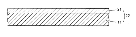
図3に示すように、本発明の製造方法により得られる長尺積層フィルム22は、長尺フィルム11と、その表面に形成された塗布層21とを備える。長尺積層フィルム22の総厚みは、好ましくは、10μm~300μmである。
図3に示すように、本発明の製造方法により得られる長尺積層フィルム22は、長尺フィルム11と、その表面に形成された塗布層21とを備える。長尺積層フィルム22の総厚みは、好ましくは、10μm~300μmである。
[実施例]
4-ニトロアニリンと8-アミノ-2-ナフタレンスルホン酸とを、常法(細田豊著「理論製造 染料化学 第5版」昭和43年7月15日技報堂発行、135頁~152頁)に従って、ジアゾ化およびカップリング反応させて、モノアゾ化合物を得た。
4-ニトロアニリンと8-アミノ-2-ナフタレンスルホン酸とを、常法(細田豊著「理論製造 染料化学 第5版」昭和43年7月15日技報堂発行、135頁~152頁)に従って、ジアゾ化およびカップリング反応させて、モノアゾ化合物を得た。
このモノアゾ化合物を、同様に常法によりジアゾ化し、さらに1-アミノ-8-ナフトール-2,4-ジスルホン酸リチウム塩とカップリング反応させて、下記構造式(1)のアゾ化合物を含む粗生成物を得た。これを、塩化リチウムで塩析することにより、下記構造式(1)のアゾ化合物を得た。
このアゾ化合物を少量採取し、水に溶解して偏光顕微鏡で観察したところ、20重量%で、ネマチック液晶相を示した。

シクロオレフィン系樹脂を含む長尺フィルム(日本ゼオン社製ゼオノア、厚み40μm)の表面に、ラビング処理とコロナ処理とを施した。
長尺フィルムのコロナ処理面に、図1に示す塗布手段を用いて、上記のアゾ化合物を含む水溶液を塗布して、塗布層を形成させた。アゾ化合物の濃度は、水溶液の総重量に対して18重量%であった。アゾ化合物を含む水溶液の粘度は、回転式粘度計(HAKKE社製RS1)の測定によると、剪断速度100s-1において、60mPa・sであった。
次に、長尺積層フィルムを40℃の恒温オーブンに入れ、塗布層から水分を除去し、長尺フィルムの表面に厚み0.4μmの固化層を形成した。このようにして、長尺フィルムと固化層との積層体からなる長尺積層フィルムを得た。
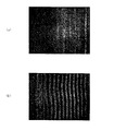
得られた長尺積層フィルムは、可視光領域で吸収二色性を示し、固化層の表面に、縞状のムラは観察されなかった(図4(a))。
[比較例]
実施例で用いた、図1に示す塗布手段のうち、長尺フィルム11の幅方向の両端部11cを押さえるニップロール16、17を用いなかった。それ以外は、実施例と同様の方法で、長尺フィルムと固化層との積層体からなる長尺積層フィルムを得た。
実施例で用いた、図1に示す塗布手段のうち、長尺フィルム11の幅方向の両端部11cを押さえるニップロール16、17を用いなかった。それ以外は、実施例と同様の方法で、長尺フィルムと固化層との積層体からなる長尺積層フィルムを得た。
得られた長尺積層フィルムの固化層の表面には、縞状のムラが観察された(図4(b))。
[測定方法]
[縞状のムラの観察]
輝度10,000cd/m2のバックライト(電通産業社製フラットイルミネータ)の上に、市販の偏光板(日東電工社製NPF-SEG1224DU)を置き、その上に、作製した光学積層フィルムを、吸収軸が直交するように配置して、目視観察した。
[縞状のムラの観察]
輝度10,000cd/m2のバックライト(電通産業社製フラットイルミネータ)の上に、市販の偏光板(日東電工社製NPF-SEG1224DU)を置き、その上に、作製した光学積層フィルムを、吸収軸が直交するように配置して、目視観察した。
[粘度]
測定サンプルの液体を0.1cc採取し、回転式粘度計(HAKKE社製RS1)を用いて、剪断速度10s-1~1,000s-1の範囲の粘度を測定した。
測定サンプルの液体を0.1cc採取し、回転式粘度計(HAKKE社製RS1)を用いて、剪断速度10s-1~1,000s-1の範囲の粘度を測定した。
本発明の製造方法により得られる長尺積層フィルムの用途は、特に制限はないが、例えば、塗布層が可視光領域で吸収二色性を示す場合、偏光板として用いるのに好適である。
11 長尺フィルム
11a 長尺フィルムの表面
11b 長尺フィルムの裏面
11c 長尺フィルムの幅方向両端部
12 第一のガイドロール
13 第二のガイドロール
13a 第二のガイドロールの回転軸
14 塗料
15 走行方向
16 ニップロール
16a ニップロールの回転軸
17 ニップロール
17a ニップロールの回転軸
18 ニップロールの回転軸の交点
19 長尺フィルムに加わる幅方向の力
20 塗布ヘッド
21 塗布層
22 長尺積層フィルム
31 長尺フィルム
31a 長尺フィルムの表面
32、33 ガイドロール
34 塗布ヘッド
35 塗料
36 塗布層
37 長尺積層フィルム
38 走行方向
11a 長尺フィルムの表面
11b 長尺フィルムの裏面
11c 長尺フィルムの幅方向両端部
12 第一のガイドロール
13 第二のガイドロール
13a 第二のガイドロールの回転軸
14 塗料
15 走行方向
16 ニップロール
16a ニップロールの回転軸
17 ニップロール
17a ニップロールの回転軸
18 ニップロールの回転軸の交点
19 長尺フィルムに加わる幅方向の力
20 塗布ヘッド
21 塗布層
22 長尺積層フィルム
31 長尺フィルム
31a 長尺フィルムの表面
32、33 ガイドロール
34 塗布ヘッド
35 塗料
36 塗布層
37 長尺積層フィルム
38 走行方向
Claims (5)
- 長尺フィルムに塗布層を積層した長尺積層フィルムの製造方法であって、
前記長尺フィルムの裏面を、第一のガイドロールと、前記第一のガイドロールよりも、走行方向の下流に配置された第二のガイドロールにより支持し、
それぞれの回転軸が走行方向の下流側で交差する一対のニップロールが、前記第一のガイドロールまたは第二のガイドロールと対向する位置に配置され、
前記一対のニップロールと、前記第一のガイドロールまたは第二のガイドロールとの間に、前記長尺フィルムの幅方向の両端部を挟み、前記長尺フィルムに幅を広げる方向の力を与えながら、前記長尺フィルムを走行させ、
前記第一のガイドロールと第二のガイドロールとの間で、前記長尺フィルムの表面に塗布ヘッドを押し付け、塗料を塗布して、塗布層を形成することを特徴とする、長尺積層フィルムの製造方法。 - 前記ニップロールの回転軸と、前記第一のガイドロールまたは第二のガイドロールの回転軸との交わる角度が、1°~10°であることを特徴とする、請求項1に記載の長尺積層フィルムの製造方法。
- 前記ニップロールが、前記長尺フィルムと、前記第一のガイドロールまたは第二のガイドロールとに、同時に接することを特徴とする、請求項1または2に記載の長尺積層フィルムの製造方法。
- 前記ニップロールの外周面が、エラストマー樹脂であることを特徴とする、請求項1または2に記載の長尺積層フィルムの製造方法。
- 前記ニップロールの外周面が、エラストマー樹脂であることを特徴とする、請求項3に記載の長尺積層フィルムの製造方法。
Applications Claiming Priority (2)
| Application Number | Priority Date | Filing Date | Title |
|---|---|---|---|
| JP2009162875A JP2011016082A (ja) | 2009-07-09 | 2009-07-09 | 長尺積層フィルムの製造方法 |
| JP2009-162875 | 2009-07-09 |
Publications (1)
| Publication Number | Publication Date |
|---|---|
| WO2011004628A1 true WO2011004628A1 (ja) | 2011-01-13 |
Family
ID=43429054
Family Applications (1)
| Application Number | Title | Priority Date | Filing Date |
|---|---|---|---|
| PCT/JP2010/052820 Ceased WO2011004628A1 (ja) | 2009-07-09 | 2010-02-24 | 長尺積層フィルムの製造方法 |
Country Status (3)
| Country | Link |
|---|---|
| JP (1) | JP2011016082A (ja) |
| TW (1) | TWI386306B (ja) |
| WO (1) | WO2011004628A1 (ja) |
Families Citing this family (2)
| Publication number | Priority date | Publication date | Assignee | Title |
|---|---|---|---|---|
| JP2012226231A (ja) * | 2011-04-22 | 2012-11-15 | Nitto Denko Corp | 長尺状円偏光板の製造方法 |
| JP2013122500A (ja) * | 2011-12-09 | 2013-06-20 | Nitto Denko Corp | 長尺積層フィルムの製造方法 |
Citations (5)
| Publication number | Priority date | Publication date | Assignee | Title |
|---|---|---|---|---|
| JPS59212347A (ja) * | 1983-05-13 | 1984-12-01 | Matsushita Electric Ind Co Ltd | エクスパンダ |
| JPH04223135A (ja) * | 1990-12-26 | 1992-08-13 | Toray Ind Inc | ウエブのシワ伸ばし装置 |
| JPH0562182A (ja) * | 1991-09-02 | 1993-03-12 | Tdk Corp | 磁気記録媒体の製造方法 |
| JP2000197843A (ja) * | 1999-01-08 | 2000-07-18 | Teijin Ltd | 複合フィルムの製造方法及びその装置 |
| JP2008284528A (ja) * | 2007-05-21 | 2008-11-27 | Toyota Motor Corp | ペーストの表裏同時塗工方法および装置 |
Family Cites Families (3)
| Publication number | Priority date | Publication date | Assignee | Title |
|---|---|---|---|---|
| US3695884A (en) * | 1970-06-18 | 1972-10-03 | Polaroid Corp | Photographic fluid container manufactured by freezing and sealing liquid |
| JPH11319677A (ja) * | 1998-05-20 | 1999-11-24 | Sony Corp | 塗布装置 |
| JPH11333360A (ja) * | 1998-05-25 | 1999-12-07 | Tdk Corp | 支持体のシワ伸ばし装置およびそれを用いた塗布装置 |
-
2009
- 2009-07-09 JP JP2009162875A patent/JP2011016082A/ja active Pending
-
2010
- 2010-02-24 WO PCT/JP2010/052820 patent/WO2011004628A1/ja not_active Ceased
- 2010-03-05 TW TW99106430A patent/TWI386306B/zh not_active IP Right Cessation
Patent Citations (5)
| Publication number | Priority date | Publication date | Assignee | Title |
|---|---|---|---|---|
| JPS59212347A (ja) * | 1983-05-13 | 1984-12-01 | Matsushita Electric Ind Co Ltd | エクスパンダ |
| JPH04223135A (ja) * | 1990-12-26 | 1992-08-13 | Toray Ind Inc | ウエブのシワ伸ばし装置 |
| JPH0562182A (ja) * | 1991-09-02 | 1993-03-12 | Tdk Corp | 磁気記録媒体の製造方法 |
| JP2000197843A (ja) * | 1999-01-08 | 2000-07-18 | Teijin Ltd | 複合フィルムの製造方法及びその装置 |
| JP2008284528A (ja) * | 2007-05-21 | 2008-11-27 | Toyota Motor Corp | ペーストの表裏同時塗工方法および装置 |
Also Published As
| Publication number | Publication date |
|---|---|
| TW201102265A (en) | 2011-01-16 |
| JP2011016082A (ja) | 2011-01-27 |
| TWI386306B (zh) | 2013-02-21 |
Similar Documents
| Publication | Publication Date | Title |
|---|---|---|
| JP6081098B2 (ja) | 長尺状積層偏光板の製造方法及び長尺状積層偏光板 | |
| KR20110033301A (ko) | 복합 필름의 제조 방법 및 복합 필름 | |
| WO2013084959A1 (ja) | 長尺積層フィルムの製造方法 | |
| CN105891929A (zh) | 光学膜的制造方法 | |
| WO2011013506A1 (ja) | 積層光学フィルムの製造方法 | |
| TWI465760B (zh) | Method for manufacturing long strip polarizing plate | |
| CN100368833C (zh) | 圆偏振片和液晶显示器 | |
| WO2011004628A1 (ja) | 長尺積層フィルムの製造方法 | |
| JP6385050B2 (ja) | 光学積層体の製造方法及び光学積層体 | |
| JP4059730B2 (ja) | 溶液製膜方法及び装置 | |
| JP5390465B2 (ja) | 光学積層体およびその製造方法 | |
| US9348074B2 (en) | Method for producing optical laminate | |
| JP2007061755A (ja) | 光学素子の製造方法 | |
| JP4654882B2 (ja) | 異方性光学膜の製造方法、異方性光学膜、および光学素子 | |
| JP5401592B2 (ja) | 支持フィルム |
Legal Events
| Date | Code | Title | Description |
|---|---|---|---|
| 121 | Ep: the epo has been informed by wipo that ep was designated in this application |
Ref document number: 10796939 Country of ref document: EP Kind code of ref document: A1 |
|
| NENP | Non-entry into the national phase |
Ref country code: DE |
|
| 122 | Ep: pct application non-entry in european phase |
Ref document number: 10796939 Country of ref document: EP Kind code of ref document: A1 |