WO2011001761A1 - 情報処理装置、情報処理方法、プログラム及び電子装置 - Google Patents
情報処理装置、情報処理方法、プログラム及び電子装置 Download PDFInfo
- Publication number
- WO2011001761A1 WO2011001761A1 PCT/JP2010/058773 JP2010058773W WO2011001761A1 WO 2011001761 A1 WO2011001761 A1 WO 2011001761A1 JP 2010058773 W JP2010058773 W JP 2010058773W WO 2011001761 A1 WO2011001761 A1 WO 2011001761A1
- Authority
- WO
- WIPO (PCT)
- Prior art keywords
- skin
- user
- area
- light
- image
- Prior art date
Links
Images


Classifications
-
- G—PHYSICS
- G06—COMPUTING; CALCULATING OR COUNTING
- G06T—IMAGE DATA PROCESSING OR GENERATION, IN GENERAL
- G06T7/00—Image analysis
- G06T7/20—Analysis of motion
-
- G—PHYSICS
- G06—COMPUTING; CALCULATING OR COUNTING
- G06V—IMAGE OR VIDEO RECOGNITION OR UNDERSTANDING
- G06V40/00—Recognition of biometric, human-related or animal-related patterns in image or video data
- G06V40/10—Human or animal bodies, e.g. vehicle occupants or pedestrians; Body parts, e.g. hands
- G06V40/107—Static hand or arm
-
- G—PHYSICS
- G06—COMPUTING; CALCULATING OR COUNTING
- G06V—IMAGE OR VIDEO RECOGNITION OR UNDERSTANDING
- G06V10/00—Arrangements for image or video recognition or understanding
- G06V10/10—Image acquisition
- G06V10/12—Details of acquisition arrangements; Constructional details thereof
- G06V10/14—Optical characteristics of the device performing the acquisition or on the illumination arrangements
- G06V10/143—Sensing or illuminating at different wavelengths
-
- G—PHYSICS
- G06—COMPUTING; CALCULATING OR COUNTING
- G06V—IMAGE OR VIDEO RECOGNITION OR UNDERSTANDING
- G06V40/00—Recognition of biometric, human-related or animal-related patterns in image or video data
- G06V40/20—Movements or behaviour, e.g. gesture recognition
- G06V40/28—Recognition of hand or arm movements, e.g. recognition of deaf sign language
-
- H—ELECTRICITY
- H04—ELECTRIC COMMUNICATION TECHNIQUE
- H04N—PICTORIAL COMMUNICATION, e.g. TELEVISION
- H04N23/00—Cameras or camera modules comprising electronic image sensors; Control thereof
Definitions
- the present invention relates to an information processing device, an information processing method, a program, and an electronic device.
- the present invention relates to an information processing method, a program, and an electronic apparatus.
- extraction techniques for extracting the shape of the user's hand there are a pattern matching method using image pattern matching, a skin region extraction method for extracting the user's skin region, and the like.
- a plurality of shape images obtained by imaging hands of various shapes and sizes are learned in advance, and a shape image that is most similar to the captured image (for example, pixel values of corresponding pixels).
- the shape of the hand displayed in the shape image that minimizes the sum of the differences is extracted as the shape of the user's hand.
- the shape of the hand in the captured image is significantly different from the shape of the hand in the shape image, or the hand in the captured image is in a state of overlapping the face or the like.
- a skin region representing the user's skin in the captured image is extracted using skin color information representing the color of human skin.
- the shape of both the face and hand is defined as the skin area. It is difficult to extract only the shape of the hand as a skin region.
- the present invention has been made in view of such a situation, and an accurate hand shape of a user is obtained from a captured image obtained by capturing the user while suppressing an increase in the amount of calculation required for a series of processes. It enables extraction at high speed.
- the present invention is based on, for example, a change in the luminance value of a pixel constituting an area corresponding to the shape of the extracted user's hand or the like on the display image on which the user is displayed. The movement can be easily detected.
- the first information processing apparatus includes an irradiation unit that irradiates the user with light having a first wavelength and light having a second wavelength different from the first wavelength, and the user.
- the first image obtained by receiving the reflected light of the light of the first wavelength irradiated to the second and the second image obtained by receiving the reflected light of the light of the second wavelength irradiated to the user From the skin display area on the display image including the skin display area on which the user's skin is displayed based on the acquisition means for acquiring the image of the image and the first and second images, the body of the user Object area extraction means for extracting an object area where an object representing a predetermined skin region is displayed, and a luminance value of a pixel constituting the object area on the display image, or a value calculated based on the luminance value
- an information processing apparatus including a distance change detecting means for detecting a relative change in a distance from said irradiation means to said object.
- an area constituted by pixels included in the upper n percent having a large luminance value is detected as the partial display area where a part of the object is displayed.
- a partial display area detecting means can be further provided.
- the portion according to a change in one of a luminance value of a pixel constituting the partial display region of the object region on the display image or a value calculated based on the luminance value.
- a change in relative distance to a part of the object displayed in the display area can be detected.
- the object area extracting means detects a shape area representing the shape of the object on the skin display area based on a distribution of luminance values of pixels constituting the skin display area on the display image, and displays the skin display.
- the object region corresponding to the shape region can be extracted from the region.
- the distance change detecting means may detect a change in a relative distance from the irradiation means to the object in accordance with a change in an average value of luminance values of pixels constituting the object area on the display image. it can.
- the first wavelength ⁇ 1 and the second wavelength ⁇ 2 satisfy the relationship of the following equation: ⁇ 1 ⁇ 2 630 nm ⁇ ⁇ 1 ⁇ 1000 nm 900 nm ⁇ ⁇ 2 ⁇ 1100 nm Can be.
- a first information processing method is an information processing method of an information processing device that detects a change in distance to a user, and the information processing device includes an irradiation unit, an acquisition unit, An object region extracting unit; and a distance change detecting unit, wherein the irradiating unit irradiates the user with light having a first wavelength and light having a second wavelength different from the first wavelength.
- the means receives the first image obtained by receiving the reflected light of the light of the first wavelength irradiated to the user and the reflected light of the light of the second wavelength irradiated to the user.
- the object region extracting means obtains the skin on the display image including the skin display region where the user's skin is displayed based on the first and second images. From the display area, the predetermined skin of the user's body An object region in which an object representing the position is displayed, and the distance change detection means either one of a luminance value of a pixel constituting the object region on the display image or a value calculated based on the luminance value
- the information processing method includes a step of detecting a change in a relative distance from the irradiating means to the object in accordance with a change in.
- the first program according to the first aspect of the present invention is an information processing apparatus including an irradiation unit that irradiates the user with light having a first wavelength and light having a second wavelength different from the first wavelength.
- a computer that controls the first image obtained by receiving the reflected light of the first wavelength light irradiated to the user, and the reflected light of the second wavelength light irradiated to the user.
- the skin display area on a display image including an acquisition means for acquiring a second image obtained by receiving light and a skin display area on which the user's skin is displayed based on the first and second images
- An object region extracting means for extracting an object region in which an object representing a predetermined skin part of the user's body is displayed, and a luminance value of a pixel constituting the object region on the display image, or the luminance value Depending on one of the change in value calculated on the basis of a program for functioning as a distance change detecting means for detecting a relative change in a distance from said irradiation means to said object.
- the first electronic device includes: an irradiation unit configured to irradiate the user with light having a first wavelength and light having a second wavelength different from the first wavelength; A first image obtained by receiving the reflected light of the irradiated light of the first wavelength, and a second image obtained by receiving the reflected light of the second wavelength of light irradiated on the user Based on the acquisition means for acquiring an image and the skin display area on the display image including the skin display area on which the user's skin is displayed based on the first and second images, the predetermined body of the user An object region extracting means for extracting an object region in which an object representing a skin region is displayed, and a luminance value of a pixel constituting the object region on the display image, or a value calculated based on the luminance value Depending on one change, The distance change detecting means for detecting a change in the relative distance from the irradiation means to the object and a predetermined process corresponding to the detection of the change in the
- the first image obtained by receiving the reflected light of the light having the first wavelength irradiated to the user, and the second wavelength irradiated to the user is obtained by receiving the reflected light of the light having the first wavelength irradiated to the user, and the second wavelength irradiated to the user.
- An object region in which an object representing a predetermined skin part of the user's body is extracted from the skin display region on the upper side, and the luminance value of the pixels constituting the object region on the display image, or the A change in relative distance from the irradiating means to the object is detected according to one change in the value calculated based on the luminance value.
- a second information processing apparatus is an information processing apparatus that extracts a shape of an object representing a predetermined skin part of a user's body from a captured image obtained by imaging the user. And an irradiation means for irradiating the user with light having a first wavelength and light having a second wavelength different from the first wavelength, and reflected light of the light having the first wavelength irradiated to the user.
- a shape region extracting means for extracting a skin region representing the skin of the user based on whether or not, and a shape region extracting means for extracting a shape region representing the shape of the object on the skin region,
- the extraction unit is configured to obtain a luminance value of a pixel constituting an area corresponding to the skin area on a display image on which the object and the user's part corresponding to an area other than the shape area on the skin area are displayed.
- the information processing apparatus extracts the shape region based on a distribution.
- the difference value calculation means can calculate the difference value obtained by normalizing a difference obtained by subtracting the luminance value of the second image from the luminance value of the first image.
- the difference value calculation means can calculate a ratio between the luminance value of the first image and the luminance value of the second image as the difference value.
- the information processing apparatus includes an irradiation unit, an acquisition unit, a difference value calculation unit, a skin region extraction unit, and a shape region extraction unit, and the irradiation unit has a first wavelength.
- the user is irradiated with light and light having a second wavelength different from the first wavelength, and the obtaining means receives the reflected light of the light having the first wavelength irradiated to the user.
- a second image obtained by receiving reflected light of the second wavelength light irradiated to the user, and the difference value calculating means is configured to acquire the first or second difference value.
- the first wavelength light and the first wavelength A difference value representing a difference in reflectance from light of a wavelength of is calculated, and the difference value calculated by the skin region extraction unit for each pixel constituting the first or second image is equal to or greater than a predetermined threshold value.
- the shape area extracting means extracts a shape area representing the shape of the object on the skin area, and extracts the shape area representing the shape of the object on the skin area.
- the area extracting means includes a luminance value of a pixel constituting an area corresponding to the skin area on the display image on which the object and the user's part corresponding to an area other than the shape area on the skin area are displayed.
- a second program is an information processing apparatus that extracts a shape of an object representing a predetermined skin part of a user's body from a captured image obtained by imaging the user,
- a computer that controls an information processing apparatus including an irradiation unit that irradiates the user with light having a first wavelength and light having a second wavelength different from the first wavelength.
- An acquisition means for acquiring a first image obtained by receiving reflected light of light having a wavelength of 2 and a second image obtained by receiving reflected light of light of the second wavelength irradiated to the user
- difference value calculating means for calculating a difference value representing a difference in reflectance between the light of the first wavelength and the light of the second wavelength for each pixel constituting the first or second image.
- a skin region extracting means for extracting a skin region representing the user's skin based on whether the difference value is equal to or greater than a predetermined threshold; and a shape region representing the shape of the object on the skin region.
- the shape area extracting means functions as the shape area extracting means for extracting the skin on the display image on which the object and the part of the user corresponding to the area other than the shape area on the skin area are displayed. This is a program for extracting the shape region based on the distribution of luminance values of pixels constituting the region corresponding to the region.
- a second electronic device is an electronic device that extracts a shape of an object representing a predetermined skin region of a user's body from a captured image obtained by imaging the user, An irradiation means for irradiating the user with light having a first wavelength and light having a second wavelength different from the first wavelength, and reflected light of the light having the first wavelength irradiated to the user.
- a skin area extracting means for extracting a skin area representing the user's skin
- a shape area extracting means for extracting a shape area representing the shape of the object on the skin area
- the shape area extracting means includes the object and the user's part corresponding to an area other than the shape area on the skin area on the display image.
- the electronic device extracts the shape region based on a distribution of luminance values of pixels constituting a region corresponding to the skin region.
- the first image obtained by receiving the reflected light of the light having the first wavelength irradiated to the user, and the second wavelength irradiated to the user is acquired, and for each pixel constituting the acquired first or second image, the light of the first wavelength and the second wavelength
- a difference value representing a difference in reflectance from light is calculated, and based on whether or not the difference value calculated for each pixel constituting the first or second image is equal to or greater than a predetermined threshold value,
- a skin region representing the user's skin is extracted, and a shape region representing the shape of the object on the skin region is extracted.
- the movement of the user's hand or the like can be easily detected.
- the second aspect of the present invention it is possible to extract a user's accurate hand shape and the like at high speed while suppressing an increase in the amount of calculation required for a series of processes.
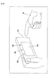
- FIG. 1 shows a configuration example of an information processing system 1 according to the present embodiment.
- the information processing system 1 executes a predetermined process according to a gesture (or posture) using a user's hand, and includes an information processing device 21, a camera 22, and a light emitting device 23.
- the user changes the shape of his / her hand (in front of the lens surface of the camera 22) or moves his / her hand.
- the information processing system 1 recognizes the shape and movement of the user's hand and executes a predetermined process corresponding to the recognition result.
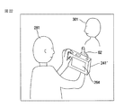
- the user moves his / her hand or changes the shape of the hand in front of the lens surface of the camera 22, and the user moves his / her hand over the lens of the camera 22 rather than the face or chest. It is assumed that a gesture (or posture) is performed at a position close to the surface.
- the information processing device 21 controls the camera 22 and the light emitting device 23. Further, the information processing apparatus 21 recognizes the shape and movement of the user's hand based on the captured image obtained by the imaging of the camera 22, and executes predetermined processing corresponding to the recognition result.
- the camera 22 has a lens used for imaging a subject such as a user, and the front surface of the lens is covered with a visible light cut filter 22a that blocks visible light.
- the camera 22 receives only the reflected light of the invisible light irradiated to the subject by the light emitting device 23, and the captured image obtained as a result is processed into the information processing device. 21 will be supplied.
- the camera 22 receives only reflected light of a first wavelength (for example, near-infrared light of 870 [nm]) that is invisible light emitted to the subject by the light emitting device 23, and is obtained as a result.
- the first captured image is supplied to the information processing device 21.
- the camera 22 is invisible light that is emitted to the subject by the light-emitting device 23 and only reflects reflected light having a second wavelength different from the first wavelength (for example, near infrared light of 950 [nm]).
- the second captured image obtained as a result of receiving light is supplied to the information processing apparatus 21.
- infrared components for example, near infrared at 870 [nm] and near infrared at 950 [nm]
- external light such as sunlight or fluorescent lamps
- the visible light region has higher light receiving sensitivity than the infrared region, the visible light influence can be reduced by providing the visible light cut filter 22a. For this reason, since the reflected light of the light irradiated to the subject can be received from the light emitting device 23 with almost no influence of visible light, the robustness of skin detection using the spectral reflectance characteristics can be improved. It becomes possible.
- the front surface of the lens of the camera 22 is covered with the visible light cut filter 22a.
- the lens of the camera 22 The front surface may be configured not to be covered with the visible light cut filter 22a.
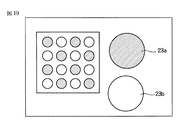
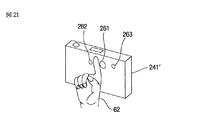
- the light emitting device 23 includes LEDs (light emitting diodes) 23a 1 and 23a 2 that emit light having a first wavelength, and LEDs 23b 1 and 23b 2 that emit light having a second wavelength.
- LED23a 1 and 23a 2 when there is no need to distinguish LED23a 1 and 23a 2 is a LED23a 1 and 23a 2 simply referred LED23a.
- LED23b 1 and 23b 2 When there is no need to distinguish LED23b 1 and 23b 2 is a LED23b 1 and 23b 2 simply referred LED23b.
- the LED 23a and the LED 23b emit light alternately according to the control of the information processing device 21.
- the output of the LED 23a and the LED 23b is such that the reflected light of the first wavelength and the reflected light of the second wavelength have the same intensity (light quantity) of the reflected light received by the camera 22. Has been adjusted.
- the relative sensitivity characteristic of the camera 22 with respect to the light of the first wavelength and the relative sensitivity characteristic of the camera 22 with respect to the light of the second wavelength are the same, the reflectance in the light of each of the first and second wavelengths.
- the brightness value obtained when irradiating light of the first wavelength to the same object (for example, mirror surface) is the same as the brightness value obtained when irradiating light of the second wavelength.
- the intensity (light quantity) of reflected light received by the camera 22 is adjusted to be the same.
- the relative sensitivity characteristic of the camera 22 usually tends to decrease in sensitivity as the distance from the visible light region increases. For example, compared with the sensitivity at 870 [nm]. , The sensitivity at 950 [nm] is 1/2 or less.
- the luminance value obtained when the light having the first wavelength is irradiated to the object having the same reflectance in the light of each of the first and second wavelengths, and the second The outputs of the LEDs 23a and 23b are adjusted according to, for example, the relative sensitivity characteristics of the camera 22 so that the luminance values obtained when the light of the wavelength is irradiated are the same.
- the LEDs 23a and the LEDs 23b are alternately arranged in a grid pattern, and a diffusion plate for uniformly diffusing the light emitted by the LEDs 23a and 23b is provided on the front surfaces of the LEDs 23a and 23b. 23c is provided. Thereby, the subject is irradiated with light of the first or second wavelength evenly.
- the light emitting device 23 is disposed at a position where the light emitted from the LED 23a or the LED 23b is reliably irradiated to at least the user's hand.
- the light emitting device 23 since the user changes the shape of the hand in front of the lens surface of the camera 22, the light emitting device 23 is disposed in a state of being close to the camera 22, for example.
- the light emitting device 23 will be described as being disposed in the vicinity of the camera 22, but the positional relationship between the light emitting device 23 and the camera 22 is not limited thereto. That is, any positional relationship may be used as long as the user's hand located in front of the lens surface of the camera 22 can be irradiated and the reflected light obtained by the irradiation can be reliably received by the camera 22. .
- the light emitting device 23 and the camera 22 that are close to each other are separated and the light emitting device 23 is disposed closer to the user's hand than the camera 22, the light emitting device 23 and the camera 22 are disposed. Compared with the case where it arrange
- the distance between the light emitting device 23 and the user's hand is shorter than when the light emitting device 23 and the camera 22 are arranged close to each other, the power consumption of the light emitting device 23 can be reduced. It becomes.
- FIG. 2 shows a configuration example of the information processing apparatus 21.
- the information processing apparatus 21 includes a control unit 41, a binarization unit 42, a skin extraction unit 43, a threshold value determination unit 44, a mask image generation unit 45, and a shape extraction unit 46.
- the control unit 41 controls the light emitting device 23 to cause the LEDs 23a and the LEDs 23b to emit light alternately.
- the first captured image and the second captured image are supplied from the camera 22 to the binarization unit 42.
- the binarization unit 42 Based on the first and second captured images supplied from the camera 22, the binarization unit 42 extracts a skin region representing the user's skin and a region other than the skin region from the first captured image ( To detect.
- the binarization unit 42 employs the first captured image as the target for extracting the skin region and the region other than the skin region.
- the target to be extracted As such, the second captured image or the like can be adopted.
- the binarization unit 42 binarizes the pixel values of the pixels constituting the extracted skin area and the pixel values of the pixels constituting the area other than the skin area (for example, 0 and 1).
- the binarized skin image thus generated is generated and supplied to the skin extraction unit 43 and the shape extraction unit 46.
- the first captured image is supplied from the camera 22 to the skin extraction unit 43 and the mask image generation unit 45.
- the skin extraction unit 43 Based on the binarized skin image supplied from the binarization unit 42, the skin extraction unit 43 extracts a region corresponding to the skin region in the binarized skin image from the first captured image from the camera 22 (user (The area where the skin part is displayed) is extracted.
- the skin extraction unit 43 generates a skin image including the extracted region and supplies the skin image to the threshold value determination unit 44.
- the skin extraction unit 43 may supply the extracted region to the threshold value determination unit 44 as a skin image.
- the threshold value determination unit 44 creates a histogram of the skin image (the luminance value of the pixels constituting the skin image) based on the skin image from the skin extraction unit 43. Then, the threshold value determination unit 44 determines a mask threshold value used for generating a mask image to be described later based on the created histogram of the skin image, and supplies it to the mask image generation unit 45.
- the threshold value determination unit 44 uses, for example, a histogram of the skin image as the distribution of the luminance values of the pixels constituting the skin image in order to determine the mask threshold value.
- a histogram of the skin image as the distribution of the luminance values of the pixels constituting the skin image in order to determine the mask threshold value.
- any information may be used as long as it represents the distribution of luminance values of pixels constituting the skin image, without being limited to the histogram of the skin image.
- the threshold value determination unit 44 calculates the maximum value or the minimum value of the luminance values of the pixels constituting the skin image based on the skin image histogram, and determines the mask threshold value. However, it is not limited to this.
- the threshold value determination unit 44 calculates an average value, a variance value, a minimum value, a maximum value, and the like for the luminance values of the pixels constituting the skin image based on the histogram of the skin image,
- the mask threshold value may be determined using a variance value, a minimum value, a maximum value, or the like.
- the mask image generation unit 45 generates a mask image from the first captured image supplied from the camera 22 based on the mask threshold value from the threshold value determination unit 44 and supplies the mask image to the shape extraction unit 46.
- the mask image is a mask area composed of pixels having luminance values included in the luminance value range specified by the mask threshold, and other areas in the first captured image. An image binarized into a mask area.
- the shape extraction unit 46 uses, for example, the user's hand as a region corresponding to the mask region in the mask image from the binarized skin image from the binarization unit 42. A shape region representing the shape is extracted.
- the shape extraction unit 46 recognizes the shape of the hand based on the extracted shape region, performs processing according to the recognition result, and outputs the processing result to the subsequent stage.
- the binarization unit 42 extracts the skin region and the region other than the skin region from the first captured image, but the skin region and the region other than the skin region are extracted from the second captured image. You may make it extract. In this case, the skin image extraction unit 43 and the mask image generation unit 45 are supplied with the second captured image from the camera 22 instead of the first captured image.
- the skin extraction unit 43 generates a skin image from the second captured image
- the mask image generation unit 45 generates a mask image from the second captured image
- the skin extraction unit 43 creates new synthesized images (for example, the first and second captured images, respectively) obtained by synthesizing the first captured image and the second captured image at a predetermined ratio.
- the skin area and the area other than the skin area are extracted for a synthesized image (a synthesized image synthesized at a ratio of 1: 1) having an average luminance value of corresponding pixels as a luminance value. May be.
- the skin extraction unit 43 is a display area in which the same subject as the subject displayed on the first or second captured image is displayed at the same position. Can be adopted as an image to be extracted.
- FIG. 5 illustrates a binarized skin image generated by the binarization unit 42 based on the first captured image and the second captured image.
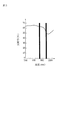
- FIG. 3 shows the reflection characteristics of human skin with respect to irradiation light having different wavelengths.
- the horizontal axis indicates the wavelength of light applied to the human skin
- the vertical axis indicates the reflectance of the light applied to the human skin.
- the reflectance of reflected light obtained by irradiating human skin with light of 870 [nm] is about 63 [%], and 950 [
- the reflectance of the reflected light obtained by irradiating [nm] light is about 50 [%].
- the change in reflectance is moderate around 800 to 1000 [nm]. Many. Although illustration is omitted, in the example of hair, the reflectance gradually increases as the wavelength increases in the vicinity of 800 to 1000 [nm]. In the example of hair, the reflectance of the reflected light obtained by irradiating light of 870 [nm] is about 6 [%], and the reflectance of the reflected light obtained by irradiating light of 950 [nm] Is about 8%.
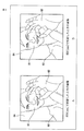
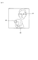
- FIG. 4 shows a first captured image obtained by receiving reflected light of 870 [nm] light irradiated to the user, and obtained by receiving reflected light of 950 [nm] light irradiated to the user. An example of each second captured image is shown.
- the user's face 61 and hand 62 are displayed as the user's skin area, and the shirt 63 and the background 64 worn by the user are displayed as areas other than the user's skin area.
- a first captured image is shown.
- the user's face 81 and hand 82 are displayed as the user's skin area, and the shirt 83 and the background 84 worn by the user are areas other than the user's skin area.
- the displayed second captured image is shown.
- the reflectance of light having a wavelength of 870 [nm] is greater than the reflectance of light having a wavelength of 950 [nm] in the reflection characteristics of the user's skin. .
- the reflected light when 950 [nm] light is applied to the lens of the camera 22 as the reflected light of the light irradiated to the user's skin. Light that is brighter than the brightness is incident.
- the luminance values of the pixels constituting the user's skin area (face 61 and hand 62) in the first captured image are the user's skin areas (face 81 and hand) in the second captured image, respectively. 82), which is larger than the luminance value of the pixels constituting the pixel 82).
- the reflectance of light having a wavelength of 870 [nm] is the same as or smaller than the reflectance of light having a wavelength of 950 [nm]. Often has become.
- the lens of the camera 22 is irradiated with light of 950 [nm] as reflected light of the light irradiated to the part other than the user's skin part.
- the luminance values of the pixels constituting the region (the shirt 63 and the background 64) other than the user's skin region in the first captured image are respectively other than the user's skin region in the second captured image.
- the value is the same as or smaller than the luminance value of the pixels constituting the region (the shirt 83 and the background 84).
- each of the luminance values of the pixels constituting the corresponding user's skin part in the second captured image from the luminance values of the pixels constituting the part other than the user's skin part in the first captured image.
- the difference obtained by subtracting is a value of 0 or less (non-positive value).
- the binarization unit 42 calculates the difference between the luminance values of the corresponding pixels in the first captured image and the second captured image, and based on the calculated difference, An area other than the user's skin area is extracted. Then, the binarization unit 42 generates a binarized skin image with the extracted user's skin area as the value 1 and the area other than the extracted user's skin area as the value 0.
- the binarization unit 42 calculates the calculated difference (difference obtained by subtracting the luminance value of the pixel constituting the corresponding second captured image from the luminance value of the pixel constituting the first captured image). Is positive, the corresponding pixel is extracted as a pixel constituting the user's skin area. If the calculated difference is not positive, the corresponding pixel is extracted as a pixel constituting an area other than the user's skin area.
- the binarization unit 42 sets the pixel value of the pixel extracted as the pixel constituting the user's skin area to 1, and sets the pixel value of the pixel extracted as the pixel constituting the area other than the user's skin area to 0
- a binarized skin image is generated and supplied to the skin extraction unit 43 and the shape extraction unit 46.
- the difference calculated in the part other than the skin part may be a positive value although it is smaller than the difference calculated in the skin part. Therefore, even if the difference is positive, if the difference is less than the predetermined threshold, it is desirable that the pixel value 0 is set as a part other than the user's skin part.
- the binarization unit 42 determines whether or not the calculated difference is equal to or greater than a predetermined threshold value. If the difference is equal to or greater than the predetermined threshold value, the corresponding pixel constitutes the user's skin area. When extracted as a pixel and not equal to or greater than a predetermined threshold, it is desirable to generate a binarized skin image by extracting the corresponding pixel as a pixel constituting an area other than the user's skin area.
- the luminance values L1 and L2 in the skin region can change due to the distance from the light emitting device 23 to the subject, the imaging conditions of the camera 22, and the like, so the difference L1-L2 in the skin region is It may happen that the constant value C1 is not reached.
- the binarizing unit 42 must use a different threshold value for each difference L1-L2, which is a very complicated process.
- the binarization unit 42 normalizes the difference L1-L2, and uses the difference L1-L2 as the difference between the reflectance of the light of the first wavelength and the reflectance of the light of the second wavelength.
- the binarization unit 42 uses the difference L1-L2 as the difference between the reflectance of the light of the first wavelength and the reflectance of the light of the second wavelength.
- the binarization unit 42 normalizes (divides) the difference L1-L2 with one of the luminance values L1 or L2, the normalized difference (L1-L2) / L1 or (L1 Since the same threshold value prepared in advance can be used for -L2) / L2, it is not necessary to prepare a different threshold value for each difference L1-L2.
- the difference may be normalized by the luminance value related value related to the luminance value L1 or L2, for example, (L1 + L2) / 2 Or you may normalize with (L1 + L2).
- the capacity of the built-in memory (not shown) for the binarization unit 42 to hold the threshold value in advance can be reduced. Further, if the binarization unit 42 uses the same threshold value regardless of the difference L1-L2, it is possible to save time and effort for changing the threshold value for each difference L1-L2. It is possible to suppress a calculation amount for generating an image and generate a binarized skin image more quickly.
- the binarization unit 42 uses the ratio L1 / L2 Is extracted as a skin region, and when the ratio L1 / L2 is less than the threshold, it is extracted as a non-skin region.
- the binarization unit 42 calculates a difference absolute value between luminance values of corresponding pixels between the first captured image and the second captured image, and the calculated difference absolute value is equal to or greater than a predetermined threshold value. Based on whether or not, the user's skin part (skin area) and other parts (areas other than the skin area) may be extracted to generate a binarized skin image.
- the same threshold value can be used for any difference absolute value by normalizing with the luminance value L1 or L2.
- the luminance value is also taken into account. It is desirable to extract the skin area. That is, for example, only a portion having a high luminance value L1 (or luminance value L2) out of the skin regions extracted using the absolute difference value may be extracted as the final skin region.
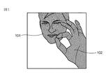
- FIG. 5 shows an example of a binarized skin image generated by the binarization unit 42.
- a black portion indicates a skin region represented by a pixel value 1.
- This skin area is composed of a face area 101 indicating the skin part of the user's face and a hand area 102 indicating the skin part of the user's hand.
- the face area 101 shown in FIG. 5 includes not only the skin part of the face but also eyebrows, eyes, hair, and the like. Consists of only.
- a white portion indicates an area other than the skin area represented by a pixel value of 0.
- the binarization unit 42 supplies the generated binarized skin image to the skin extraction unit 43 and the shape extraction unit 46.
- the skin extraction unit 43 Based on the binarized skin image from the binarization unit 42, the skin extraction unit 43 converts the first captured image supplied from the camera 22 into the face area 101 and the hand area 102 in the binarized skin image. A corresponding area (area where the face 61 and the hand 62 are displayed) is extracted. And the skin extraction part 43 produces
- FIG. 6 shows an example of the skin image extracted by the skin extraction unit 43.
- the user's face 61 and hand 62 are displayed in the skin image shown in FIG.
- the skin image shown in FIG. 6 includes eyebrows, eyes, hair, and the like as the user's face 61 in addition to the skin portion of the face.
- the face 61 represents only the skin portion of the face.
- the skin extraction unit 43 multiplies the luminance values of corresponding pixels of the binarized skin image from the binarization unit 42 and the first captured image from the camera 22, respectively.
- the skin extraction unit 43 extracts and extracts an area (area where the face 61 and the hand 62 are displayed) composed of pixels whose multiplication result is not 0 from the pixels constituting the first captured image. A skin image including the region is generated.
- the face 61 included in the area corresponding to the face area 101 of the binarized skin image and the area corresponding to the hand area 102 of the binarized skin image are included.
- the hand 62 is extracted as it is, and the brightness value of the area corresponding to the area other than the skin area of the binarized skin image (shown in white in FIG. 6) is set to the value 255, for example.
- a skin image as shown in FIG. 6 is generated from the captured image.
- the skin extraction unit 43 supplies the generated skin image to the threshold value determination unit 44.
- the threshold determination unit 44 determines a mask threshold used for generating a mask image based on the skin image from the skin extraction unit 43.
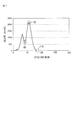
- FIG. 7 shows an example of the histogram of the skin image.
- the horizontal axis indicates the luminance value of the pixels constituting the skin image.
- the vertical axis indicates the number of pixels corresponding to the luminance value on the horizontal axis.
- the number of pixels for the luminance value 255 of the pixels constituting the area represented by the white part is also displayed in the skin image of FIG. 6. The number is not shown because it is not used to determine the mask threshold.
- the threshold value determination unit 44 creates a histogram as shown in FIG. 7 for the luminance values of the pixels constituting the skin image from the skin extraction unit 43.
- the LED 23a and the LED 23b of the light emitting device 23 emit light in the state of being close to the camera 22, so that the luminance value of the user's part (in this case, a hand) existing closer to the camera 22 (light emitting device 23) is larger. Increases, and the luminance value decreases as the user part (in this case, a face or the like) exists farther from the camera 22.
- the luminance value of the pixels constituting the skin portion of the hand existing at a position close to the camera 22 is larger than the luminance value of the pixels constituting the skin portion of the face existing at a position far from the camera 22.
- the luminance values from the luminance value 0 to the luminance value 54 are the luminance values of the pixels constituting the face 61 (region), and the luminance values from the luminance value 55 to the luminance value 110 constitute the hand 62. This is the luminance value of the pixel.
- the threshold value determination unit 44 determines the luminance value (luminance value 55 in this example) when the number of pixels is a minimum as the lower threshold value Th_L, and sets the maximum luminance value (luminance value 110 in this example) as the upper threshold value Th_H. decide.
- the upper limit threshold Th_H is determined to be the maximum luminance value
- the threshold value determination unit 44 can also determine the mask threshold value using an average value, a variance value, a minimum value, a maximum value, and the like regarding the luminance values of the pixels constituting the skin image.
- the threshold value determination unit 44 may determine the average value for the luminance value of the pixels constituting the skin image as the lower limit threshold value Th_L, or the maximum value for the luminance value of the pixels constituting the skin image. One half of the value may be determined as the lower limit threshold Th_L. For example, the threshold determination unit 44 may determine the average of the minimum value and the maximum value of the luminance values of the pixels constituting the skin image as the lower limit threshold Th_L.
- the threshold value determination unit 44 prepares a threshold value determination function for determining the lower limit threshold value Th_L for each variance value, for example, and the threshold value corresponding to the variance value for the luminance value of the pixels constituting the skin image.
- the lower limit threshold Th_L may be determined by a determination function.
- the threshold value determining function for example, a function having a minimum value, a maximum value, or the like for the luminance value of the pixels constituting the skin image as a variable can be adopted.
- a function f (x) is generated, and a first derivative f ′ (x) is further generated from the generated function f (x), and a lower limit is set based on the first derivative f ′ (x). Since the value determined as the lower limit threshold Th_L can be easily calculated as compared with the case where the threshold Th_L is determined, the lower limit threshold Th_L can be determined more quickly.
- the threshold value determination unit 44 determines, for example, the maximum value of the luminance value of the pixels constituting the skin image as the upper limit threshold value Th_H, but the skin image is determined in the same manner as in the case of the lower limit threshold value Th_L.
- the upper threshold value Th_H can be determined using an average value, a variance value, a minimum value, a maximum value, and the like regarding the luminance values of the constituent pixels.
- the upper threshold value Th_H can be determined in the same manner as the lower threshold value Th_L.
- the threshold determination unit 44 supplies the determined lower limit threshold Th_L and upper limit threshold Th_H to the mask image generation unit 45 as mask thresholds.
- the mask image generation unit 45 detects a mask region and a non-mask region from the first captured image from the camera 22 based on the mask threshold values (lower threshold value Th_L and upper threshold value Th_H) from the threshold value determination unit 44, A mask image in which the detected mask area and non-mask area are binarized to different values is generated.
- the mask image generation unit 45 is present at a position close to the light emitting device 23, and therefore, as a region corresponding to a user part (in this case, a hand) whose luminance value is large, a lower threshold value Th_L or more.
- a mask region constituted by pixels having a luminance value equal to or lower than the upper threshold value Th_H is detected.
- the mask image generation unit 45 is located at a position far from the light emitting device 23, and therefore the lower threshold value Th_L is set as an area corresponding to a user part (in this case, a face) whose luminance value is small. A non-mask area composed of pixels having a luminance value not included in the range equal to or higher than the upper threshold value Th_H is detected.
- the mask image generation unit 45 generates a mask image in which the detected mask area and non-mask area are binarized to different values.
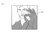
- FIG. 8 shows an example of a mask image.
- a mask area 121 shown in black indicates an area in the corresponding first captured image whose luminance value is not less than the lower threshold Th_L and not more than the upper threshold Th_H. Yes.
- the non-mask area shown in white is an area in the corresponding first captured image that is less than the lower threshold Th_L or greater than the upper threshold Th_H. Is shown.
- the mask image generation unit 45 masks the pixel having the luminance value when the luminance value of the pixel constituting the first captured image from the camera 22 is equal to or higher than the lower limit threshold Th_L and equal to or lower than the upper limit threshold Th_H.
- the pixel is detected as a pixel included in the region, and the luminance value is converted to a pixel value of 1.
- the mask image generation unit 45 A pixel having a luminance value is detected as a pixel included in the non-mask area, and the luminance value is converted to a pixel value of zero.
- the pixel value after conversion is a value different from the luminance value, and represents a value that is either 0 or 1.
- the mask image generation unit 45 is configured by a mask region 121 (shown in black) configured by pixels having a value of 1 and a non-mask region (shown in white) configured by pixels having a value of 0.
- a mask image is generated and supplied to the shape extraction unit 46.
- the threshold value determination unit 44 determines the lower limit threshold value Th_L and the upper limit threshold value Th_H. However, for example, one of the lower limit threshold value Th_L and the upper limit threshold value Th_H may be determined as the mask threshold value.
- the maximum luminance value of the pixels constituting the first captured image supplied from the camera 22 to the mask image generation unit 45 is a luminance value corresponding to human skin (for example, the luminance value 110 in FIG. 7).
- the threshold value determination unit 44 may determine only the lower limit threshold value Th_L (for example, the luminance value 55) as the mask threshold value.
- the mask image generation unit 45 when the luminance value of the pixel constituting the first captured image from the camera 22 is equal to or higher than the lower limit threshold Th_L, the mask image generation unit 45 includes the pixel having the luminance value in the mask area. And the luminance value is converted into a pixel value of 1. Further, when the luminance value of the pixel constituting the first captured image from the camera 22 is less than the lower limit threshold Th_L, the mask image generation unit 45 includes the pixel having the luminance value in the non-mask area. And the luminance value is converted to a pixel value of 0.
- the threshold value determination unit 44 determines only the upper limit threshold value Th_H as the mask threshold value, for example, the shape of the face 61 may be extracted instead of the shape of the hand 62. At this time, for example, the threshold value determination unit 44 determines the luminance value 55 shown in FIG. 7 as the upper limit threshold value Th_H as the mask threshold value.
- the shape extraction unit 46 changes the face region 101 and the hand region 102 in the binarized skin image from the binarization unit 42 to the mask region 121 in the mask image.
- the corresponding region for example, a shape region representing the shape of the user's hand is extracted.
- the shape extraction unit 46 is located closer to the light emitting device 23 on the basis of the mask region 121 and the non-mask region that form the mask image from the mask image generation unit 45, and thus the luminance value increases.
- the user's part in this case, the hand 62
- the part of the user corresponding to the mask area 121 and the part of the user whose luminance value is small present now
- the difference in the relative distance from the light emitting device 23 to the face 61) (the part of the user corresponding to the non-mask area) is distinguished.
- the shape extraction unit 46 is located at a position close to the light emitting device 23 due to the difference in relative distance from the distinguished light emitting device 23, for example.
- the shape region (in this case, the region representing the shape of the hand) is extracted by distinguishing the hand 62).
- FIG. 9 shows a display example of an extracted image including a shape region extracted by the shape extraction unit 46.
- the shape region 141 represents the shape of the user's hand.
- the shape extraction unit 46 multiplies the value of the pixel constituting the mask image from the mask image generation unit 45 and the value of the pixel constituting the binarized skin image from the corresponding binarization unit 42, respectively. .
- the shape extraction unit 46 determines that the multiplication result is not 0 in the binarized skin image, that is, the face region 101 and the hand region 102 (FIG. 5) in the binarized skin image. A portion overlapping the mask region 121 (FIG. 8) is extracted as the shape region 141.
- the shape extraction unit 46 recognizes the shape of the user's hand based on the extracted shape region 141, and performs processing according to the recognition result.
- the mask region 121 in the mask image shown in FIG. 8 includes a shirt worn by the user in addition to the user's hand.
- the shape extraction unit 46 does not extract an area representing the shape of the shirt, The shape region 141 representing only the hand shape can be accurately extracted.
- FIG. 10 is a flowchart for explaining the shape extraction process. This shape extraction process is repeatedly executed from when the information processing system 1 is powered on.
- step S1 the control unit 41 controls the LED 23a of the light emitting device 23 to start light emission of the first wavelength. In addition, when the LED 23b emits light, the control unit 41 stops light emission of the LED 23b and starts light emission of the LED 23a.
- step S ⁇ b> 2 the camera 22 captures an image of a user irradiated with light having the first wavelength, and supplies a first captured image obtained as a result to the information processing apparatus 21.
- step S3 the control unit 41 controls the LED 23a of the light emitting device 23, stops the light emission of the first wavelength light, controls the LED 23b of the light emitting device 23, and starts the light emission of the second wavelength. .
- step S ⁇ b> 4 the camera 22 captures an image of a user irradiated with light of the second wavelength, and supplies a second captured image obtained as a result to the information processing apparatus 21.
- step S5 the binarizing unit 42, as shown in FIG. 5, based on the difference between the luminance values of the corresponding pixels of the first captured image and the second captured image supplied from the camera 22.
- a binarized skin image is generated and supplied to the skin extraction unit 43 and the shape extraction unit 46.
- step S ⁇ b> 6 the skin extraction unit 43 corresponds to the skin region in the binarized skin image from the first captured image from the camera 22 based on the binarized skin image supplied from the binarization unit 42. To be extracted (region where the user's skin part is displayed).
- the skin extraction unit 43 generates a skin image including the extracted region and supplies the skin image to the threshold value determination unit 44.
- step S7 the threshold value determination unit 44 creates a skin image histogram as shown in FIG. 7 based on the luminance values of the pixels constituting the skin image from the skin extraction unit 43.
- step S8 the threshold determination unit 44 determines the luminance value when the number of pixels is minimum based on the created skin image histogram as the lower limit threshold Th_L, and determines the maximum luminance value as the upper limit threshold Th_H. .
- the threshold value determination unit 44 supplies the determined lower threshold value Th_L and upper limit threshold value Th_H to the mask image generation unit 45 as mask threshold values.
- step S9 the mask image generation unit 45 binarizes the first captured image from the camera 22 based on the mask thresholds (the lower limit threshold Th_L and the upper limit threshold Th_H) from the threshold determination unit 44, and FIG. A mask image as shown is generated and supplied to the shape extraction unit 46.
- step S10 the shape extraction unit 46, based on the mask image from the mask image generation unit 45, as a region corresponding to the mask region in the mask image from the binarized skin image from the binarization unit 42, for example, An extraction area representing the shape of the user's hand is extracted.
- the shape extraction unit 46 recognizes the shape of the hand from the extracted extraction region, performs processing according to the recognition result, and outputs the processing result to the subsequent stage.
- a mask image is generated from the first captured image captured by one camera 22 based on the mask threshold, and binarized skin is generated based on the generated mask image.
- the shape of the user's hand was extracted from the image.
- a distance image representing the distance between the camera and the user's hand or the like is generated, and the distance image is used as a mask image to generate a user's hand.
- the amount of calculation required to generate the mask image can be reduced, and the shape of the user's hand and the like can be extracted with a smaller number of parts.
- the skin part of the face is not included as the skin part, and only the skin part of the hand is included.
- a mask image including the mask area 121 included and the non-mask area is generated.
- the mask region 121 includes the skin portion as the skin portion. Since only the skin portion of the hand is included without including the skin portion of the face, only the hand region 102 can be extracted from the binarized skin image.
- the light emitted from the LED 23a and the LED 23b is dazzling, so that the user does not feel unpleasant.
- a diffusion plate 23c is provided in front of the LED 23a and the LED 23b.
- the invisible light emitted by the LEDs 23a and 23b is uniformly diffused, the subject is irradiated with uniform light without unevenness due to the amount of light.
- the reflected light of the invisible light irradiated to the subject is received by the camera 22 as uniform light without unevenness due to the amount of light, so that the camera 22 displays the first and second captured images without unevenness due to the amount of light. Obtainable.
- the information processing system 1 uses the first and second captured images without unevenness due to the light amount in order to extract the hand shape and the like, for example, the first and second captured images with unevenness due to the light amount. Compared with the case of using, the shape of the hand and the like can be extracted more accurately.
- the information processing system 1 for example, in about 80 [ms] from the start of the shape extraction process so that the user can recognize the changed hand shape every time the user changes the hand shape. It is desirable to configure so that the shape of the hand can be extracted.
- the hand shape is desirable to configure to be extracted within 80 [ms] from the start of the shape extraction process. This is because it is known from experiments and the like conducted in advance that the user hardly feels stress when the processing time for extracting the hand shape is within 80 [ms].
- the difference L1-L2 is calculated and normalized, and the shape of the hand is extracted by a very simple process of comparing with the threshold value. Even when using an inexpensive and low-speed CPU (Central Processing Unit), processing time within 80 [ms] can be easily realized.
- CPU Central Processing Unit
- the processing time within 80 [ms] can be easily realized, so that the manufacturing cost can be suppressed and the user can be stressed. It is possible to quickly perform a process of extracting the shape of the hand without causing the user to feel.
- the shape of the hand 62 can be accurately extracted even when, for example, the face 61 and the hand 62 overlap as a skin region.
- the user wears a short-sleeved shirt or the like, it is also conceivable that the user's face 61 and the hand 62 as well as the arm or the like overlap.
- the skin extraction unit 43 extracts a skin image on which the arm 63 is displayed in addition to the face 61 and the hand 62 as shown in FIG. A histogram as shown in FIG.
- FIG. 12 shows an example of a histogram generated based on the skin image as shown in FIG.
- the distance from the light emitting device 23 to the hand 62 is the first closest (shorter), and the distance from the light emitting device 23 to the arm 63 is the same.
- the distance is the second closest, and the distance from the light emitting device 23 to the face 61 is the third closest.
- the histogram of the skin image shown in FIG. 11 is a pixel corresponding to the face 61 of the user from the brightness value 0 to the brightness value 75 as shown in the uppermost part of FIG. 12 (indicated by the solid line).
- the pixels from the luminance value 76 to the luminance value 150 are pixels corresponding to the user's arm 63, and the pixels having the luminance value 151 to the luminance value 250 are pixels corresponding to the user's hand 62.
- the histogram at the luminance values 76 to 150 corresponding to the arm 63 is flat. Therefore, unlike the histogram shown in FIG. 7, there is no clear minimum value (the luminance value 55 in FIG. 7) that distinguishes the face 61 from the hand 62. For this reason, the lower limit threshold Th_L cannot be determined in the same manner as described with reference to FIG.
- the threshold value determination unit 44 determines the shape of the histogram based on the histogram to be generated, and refers to a different method (for example, the method described in FIG. 7 or FIG. 12 according to the determined shape of the histogram.
- the lower limit threshold Th_L and the like are determined by the method described below.
- the threshold value determination unit 44 determines, for example, the lower limit threshold value Th_L based on the histogram shown in FIG. 12 will be described.
- a luminance value representing a boundary between the luminance value corresponding to the face 61 and the luminance value corresponding to the arm 63 (in this case, a luminance value near the value 75)
- the luminance value representing the boundary between the luminance value corresponding to the arm 63 and the luminance value corresponding to the hand 62 (in this case, the luminance value near the value 150) is an inflection point of the function g (x), that is, the first order. It is known that the derivative g ′ (x) is x when the maximum value or the minimum value is reached.
- the threshold value determination unit 44 differentiates the generated function g (x) once to generate a first derivative g ′ (x).
- X x0 is calculated.
- the closest value (for example, x0 when x2 ⁇ x0 is the smallest) (in this case, the luminance value 150) is determined as the lower limit threshold Th_L.
- the threshold value determination unit 44 determines, for example, the upper limit threshold value Th_H as the maximum value of luminance values in the histogram shown in FIG. 12 (in this case, the luminance value 250).
- the lower limit threshold Th_L and the upper limit threshold Th_H determined in this way are used to generate a mask image used when extracting the shape of the hand 62.
- the closest value (for example, x0 when x0-x1 is the smallest) (in this case, the luminance value 75) is determined as the lower limit threshold Th_L, and the upper limit threshold Th_H is determined as the luminance value in the histogram shown in FIG.
- the maximum value (in this case, the luminance value 250) may be determined.
- the lower threshold value Th_L and the upper threshold value Th_H determined in this way are used to generate a mask image used when extracting the shape formed by the hand 62 and the arm 63.
- the threshold determination unit 44 sets the lower limit threshold Th_L to the luminance value 75.
- the upper threshold value Th_H is determined as the luminance value 150, respectively.
- the lower limit threshold Th_L and the upper limit threshold Th_H are determined as described with reference to FIGS. 11 and 12, for example, even if a part of each of the face 61, the hand 62, and the arm 63 overlaps, For example, the shape and the like of the hand 62 can be accurately extracted.
- the threshold value determination unit 44 differentiates the first derivative g ′ (x) to obtain 2
- the shape extraction unit 46 corresponds to the shape region extracted from the skin image from the skin extraction unit 43.
- the corresponding region is detected, and the luminance value distribution of the pixels constituting the detected corresponding region is represented by, for example, the light emitting device 23 among the ones displayed in the corresponding region based on the histogram of the corresponding region. Only regions corresponding to those present at close positions can be extracted.
- the shape extraction unit 46 extracts only the region corresponding to the fingertip of the index finger from the region of the hand 62. be able to.
- the fingertip of the index finger of the hand 62 exists at a position closest to the light emitting device 23.
- FIG. 14 shows an example of the histogram of the corresponding region.
- the histogram shown in the uppermost part of FIG. 14 shows a histogram for only the luminance values of the pixels constituting the corresponding area where the hand 62 is displayed, for example.
- the histogram shown in the uppermost part of FIG. 14 shows a histogram for only the luminance values of the pixels constituting the corresponding area where the hand 62 is displayed, for example.
- the histogram shown in the uppermost part of FIG. 14 shows a histogram for only the luminance values of the pixels constituting the corresponding area where the hand 62 is displayed, for example.
- FIG. 14 shows a histogram for only the luminance values of the pixels constituting the corresponding area where the hand 62 is displayed, for example.
- the skin extracting unit 43 For example, based on the binarized skin image from the binarizing unit 42 and the first captured image from the camera 22, the skin extracting unit 43 generates a skin image as shown in FIG.
- the data is supplied to the shape extraction unit 46.
- the shape extraction unit 46 detects the corresponding region corresponding to the extracted shape region from the skin image from the skin extraction unit 43, and based on the luminance value of the pixels constituting the detected corresponding region, the shape extraction unit 46 is shown in FIG. A histogram is generated.
- the shape extraction unit 46 uses the range where the luminance value is high among the luminance values constituting the generated histogram as a tip region representing the fingertip of the index finger from the skin image (corresponding region) from the skin extraction unit 43. Can be extracted.
- the distance between the light emitting device 23 and the fingertip of the index finger is the closest among the various parts of the user's skin. For this reason, in the histogram shown in FIG. 14, the luminance value corresponding to the fingertip of the index finger is the highest.
- the area of the fingertip portion of the index finger is relatively small. Accordingly, the corresponding portion in the histogram of FIG. 14 is flat without having an extreme value, like the portion corresponding to the arm 63 of FIG.
- n [%] is determined in accordance with the part to be extracted or the like by an experiment or the like performed in advance.
- the shape extraction unit 46 performs a corresponding process according to the extracted tip region (the shape and the like).
- the ratio d2 / d1 between the relative distance d1 from the light emitting device 23 to the fingertip of the user's index finger and the relative distance d2 from the light emitting device 23 to the base of the user's index finger is, for example, the light emitting device 23. And the distance from the user's hand increases.
- the number of pixels at the fingertip portion of the index finger is small, but the luminance value of the pixel is the luminance value of the pixel at the base portion of the index finger. Since a histogram that is sufficiently large (for example, a luminance value that falls within the upper n [%]) is obtained, the fingertip portion of the user's index finger can be extracted relatively accurately.
- the shape extraction unit 46 detects the corresponding region corresponding to the extracted shape region from the skin image from the skin extraction unit 43, but the target of the image for detecting the corresponding region is It is not limited to this.
- the shape extraction unit 46 may be supplied with the first captured image from the camera 22, and the corresponding region may be detected for the first captured image.
- the second captured image may be targeted.
- the shape extraction unit 46 may target any image as long as it is a display image in which the same subject as that displayed on the first or second captured image is displayed at the same position. .
- the skin extraction unit 43 supplies the extracted skin image to the shape extraction unit 46, but the shape extraction unit 46 supplies the extracted shape region to the skin extraction unit 43.
- the skin extraction unit 43 detects the corresponding region corresponding to the shape region from the shape extraction unit 46 from the extracted skin image, and among the ones displayed in the corresponding region, the light emitting device 23 Only the region corresponding to the one existing at the closest position may be extracted.
- the histogram generated based on the skin image from the skin extraction unit 43 shows clearly the luminance value corresponding to the fingertip of the index finger as shown in FIG. 14 (for example, As shown in FIG. 14, when the brightness value of the histogram corresponding to the fingertip of the index finger is flat), the area corresponding to the brightness value of the upper n [%] is used as the mask area.
- a mask threshold can be determined.
- the threshold determination unit 44 includes the upper n [%].
- the minimum brightness value is determined as the lower limit threshold Th_L
- the maximum value among the plurality of brightness values constituting the histogram is determined as the upper limit threshold Th_H.
- the shape extraction unit 46 the shape of the fingertip portion of the index finger existing closest to the light emitting device 23 in the user's skin region is extracted from the binarized skin image from the binarization unit 42. It becomes.
- the information processing system 1 uses, for example, the fact that the brightness value of the user's skin area increases as the distance from the light emitting device 23 increases, and the brightness value decreases as the distance from the light emitting device 23 increases.
- the corresponding processing can be performed by recognizing the movement in the direction of the light emitting device.
- the so-called mouse click operation or determination operation is performed in conjunction with the movement of the user's hand in the front-rear direction, that is, the direction of the light emitting device 23 (z direction).
- the hand is moved in the z direction, it also moves in the xy direction, causing a problem that a desired content cannot be selected.
- the following method can solve the problem.
- the shape extraction unit 46 corresponds to a corresponding region (for example, a hand is displayed) corresponding to a shape region (for example, a region representing the shape of a hand) extracted from the first captured image obtained by the image capturing by the camera 22. Area) is extracted. Then, the shape extraction unit 46 detects the position of the hand based on the luminance values of the pixels constituting the extracted corresponding area.
- the shape extraction unit 46 can employ the second captured image in addition to the first captured image as a target for extracting the corresponding region. That is, the shape extraction unit 46 displays a display image (including the first and second captured images) in which the same subject as the subject displayed on the first or second captured image is displayed at the same position. As a target, a corresponding area can be extracted.
- step S21 the control unit 41 to the shape extraction unit 46, the camera 22, and the light emitting device 23 of the information processing device 21 perform the shape extraction process described with reference to FIG. As a result, the shape extraction unit 46 extracts a shape region from the binarized skin image from the binarization unit 42 based on the mask image from the mask image generation unit 45.
- step S ⁇ b> 22 the shape extraction unit 46 detects coordinates (x, y) t based on the extracted shape region. Specifically, for example, the shape extraction unit 46 calculates the center of gravity (x, y) of the extracted shape region as coordinates (x, y) t .
- step S23 the shape extraction unit 46 detects a corresponding region (for example, a region where a hand is displayed) corresponding to the extracted shape region among all the regions on the first captured image from the camera 22.
- the shape extraction unit 46 is assumed to be supplied with the first captured image from the camera 22.
- the shape extraction unit 46 calculates the average value (average luminance value) Y t of the luminance values of the pixels constituting the corresponding area based on the detected luminance values of the pixels constituting the corresponding area.
- step S24 the shape extraction unit 46 stores the calculated coordinates (x, y) t and the average luminance value Y t in the built-in memory in association with the calculated t-th order.
- step S25 the shape extraction unit 46 reads out the average luminance value Y t-1 stored in the previous step S24 among the average luminance values Y 1 to Y t-1 stored in the built-in memory.
- the shape extraction unit 46 skips step S25 and proceeds to step S26.
- step S25 the shape extraction unit 46, the magnitude of the calculated average luminance value Y t, i.e., for example, from the calculated average luminance value Y t, minus the average luminance value Y t-1 read out by the internal memory to obtain Whether or not the relative distance from the light emitting device 23 to the subject has largely changed is determined based on whether or not the absolute value of the difference Y t ⁇ Y t ⁇ 1 is less than a predetermined threshold value.
- the shape extraction unit 46 changes or increases the relative distance from the light emitting device 23 to the subject based on whether or not the difference Y t ⁇ Y t ⁇ 1 is positive. It can also be determined whether or not it has changed.
- step S25 when the shape extraction unit 46 determines that the relative distance from the light emitting device 23 to the subject has not changed significantly, the process proceeds to step S26.
- step S26 the shape extraction unit 46 controls display on a display device (not shown) based on the calculated coordinates (x, y) t . Specifically, for example, the shape extraction unit 46 moves the pointer displayed on the screen of the display device to a position corresponding to the calculated coordinates (x, y) t .
- step S26 After the process of step S26 is completed, the process returns to step S21, and thereafter the same process is performed.
- step S25 If the shape extraction unit 46 determines in step S25 that the relative distance from the light emitting device 23 to the subject has changed significantly, the process proceeds to step S27.
- step S27 the shape extraction unit 46 displays the coordinates (x, y) tk stored in the built-in memory, for example, on the screen of the display device (not shown) corresponding to the coordinates (x, y) t-5. Assuming that a so-called click operation has been performed at the position, processing based on the click operation is performed, the processing returns to step S21, and thereafter the same processing is performed.
- the shape extraction unit 46 based on the average luminance value Y t, and from the light emitting device 23 so as to determine whether the relative distance to the object has changed significantly Therefore, it is possible to recognize a gesture such as a click operation by the user.
- step S27 the shape extraction unit 46 displays a screen of a display device (not shown) corresponding to, for example, coordinates (x, y) t-5.
- the processing based on the click operation is performed assuming that the click operation has been performed at the upper position.
- the above-described processing may be performed by adopting a region representing a shape formed by the hand and the arm in addition to the region representing the shape of the hand as the shape region.
- the shape extraction unit 46 extracts only the fingertip (tip) portion of the index finger from the hand shape extracted as the shape region as described with reference to FIGS. 13 and 14. Based on the average luminance value Y t of the luminance values of the pixels constituting the area where the extracted fingertip portion is displayed, it is determined whether or not the relative distance between the light emitting device 23 and the fingertip portion has changed significantly. You may do it.
- the average luminance value Y t is used in the coordinate detection processing, how is the region corresponding to the shape region (for example, the region where the hand 62 is displayed) extracted by the shape extraction unit 46? Even if it changes, the average luminance value Y t can always be calculated.
- step S23 the shape extraction unit 46, based on the luminance values of the pixels constituting the extracted corresponding region has been to calculate the average luminance value Y t of the luminance values of the pixels constituting the corresponding region.
- the maximum value, the minimum value, the variance value, or the like of the luminance values of the pixels constituting the corresponding area may be used instead of the average luminance value Yt .
- the shape extraction unit 46 determines the relative distance from the light emitting device 23 to the subject based on whether or not the absolute value of the difference Y t ⁇ Y t ⁇ 1 is less than a predetermined threshold.
- a predetermined threshold for example, an average luminance value Y s obtained at a predetermined distance from the light emitting device 23 is prepared in advance, and the calculated average luminance value Y t and The relative distance from the light emitting device 23 is determined by comparing the average brightness value Y s prepared in advance with a position at a predetermined distance from the light emitting device 23 as a reference position, and depending on how far from the reference position. It is also possible to detect a change in.
- the mask threshold value determined in the previous step S6 to step S8 may be used as it is.
- steps S6 to S8 can be omitted, it is possible to quickly extract the shape of the hand by the shape extraction processing.
- the process in steps S6 to S8 is performed in the shape extraction process. Processing can be omitted.
- determining the mask threshold in advance for example, determining the mask threshold based on the average value of the luminance values of the pixels constituting a part of the user's hand region Is possible.
- the threshold value determination unit 44 determines a mask threshold value based on the average value of the luminance values of the pixels constituting the user's hand region, and an FFT (fast fourier transform) threshold value. The determination process will be described.
- FIG. 16 shows an example of a first captured image obtained by capturing an image of a user irradiated with light of 870 [nm].
- the threshold determination unit 44 When performing the FFT threshold determination process, the threshold determination unit 44 is supplied with a plurality of first captured images obtained by imaging the user waving with the camera 22 from the camera 22.
- the threshold value determination unit 44 performs FFT processing on the plurality of first captured images, and detects a part of the hand region in the first captured image that is moving at a constant frequency.
- the threshold value determination unit 44 calculates the average value ave_L of the luminance values of the pixels constituting the rectangular area 161 that is a part of the detected hand area.
- the threshold determination unit 44 determines a value ave_L-a obtained by subtracting the adjustment value a from the average value ave_L as the lower limit threshold Th_L, and a value ave_L + b obtained by adding the adjustment value b from the average value ave_L. Is determined as the upper threshold value Th_H.
- the adjustment values a and b are values used to adjust the average value ave_L to determine the lower threshold value Th_L and the upper threshold value Th_H.
- the adjustment values a and b depend on the intensity of light emitted from the LEDs 23a and 23b (the amount of light), the distance from the camera 22 to the user, and the sensitivity of the light from the CCD (charge coupled device image sensor) used in the camera 22. In practice, it is often calculated experimentally.
- FIG. 17 is a flowchart for explaining the FFT threshold value determination process. This FFT threshold value determination process is started, for example, when the information processing system is turned on and before the shape extraction process is performed.
- step S31 the control unit 41 controls the LED 23a of the light emitting device 23 to start light emission of the first wavelength.
- step S32 the control unit 41 controls a display (not shown), a speaker, and the like provided in the information processing apparatus 21, and instructs the user to start an operation of waving.
- step S ⁇ b> 33 the camera 22 captures an image of a user who is performing a waving operation, and supplies a plurality of first captured images obtained as a result to the threshold value determination unit 44 of the information processing apparatus 21.
- step S34 the threshold value determination unit 44 performs FFT processing on the plurality of first captured images, and detects a hand region in the first captured image that is moving at a constant frequency.
- step S35 the threshold value determination unit 44 calculates the average value ave_L of the luminance values of the pixels constituting the rectangular area 161 which is a part of the detected hand area.
- Step S36 the threshold value determination unit 44 determines a value ave_L-a obtained by subtracting the adjustment value a from the average value ave_L as the lower limit threshold Th_L, and a value ave_L + obtained by adding the adjustment value b to the average value ave_L b is determined as the upper threshold value Th_H.
- the FFT processing is performed on the plurality of first captured images to detect the hand area in the first captured image, and the luminance value constituting the pixels in the hand area.
- the mask threshold values lower threshold value Th_L and upper threshold value Th_H are determined based on the average value, the present invention is not limited to this.
- the hand threshold value may be detected, and the mask threshold value may be determined based on the average value of the luminance values constituting the pixels in the hand region.
- the binarization unit 42 extracts a user's skin region and a region other than the user's skin region from the first captured image, and includes the extracted skin region and a region other than the skin region.
- the binarized skin image is supplied to the skin extraction unit 43 and the shape extraction unit 46, the invention is not limited to this.
- the binarization unit 42 extracts the user's skin area from the first captured image, and converts the binarized skin image including at least the extracted skin area into the skin extraction unit 43 and the shape extraction unit 46. You may make it supply to.
- the skin extraction unit 43 extracts a region corresponding to the skin region included in the binarized skin image from the binarization unit 42 from the first captured image from the camera 22. Further, the shape extraction unit 46 extracts a shape region from the skin region included in the binarized skin image from the binarization unit 42.
- the mask image generation unit 45 detects a mask area and a non-mask area, for example, from the first captured image, and generates a mask image composed of the detected mask area and non-mask area.
- a mask area and a non-mask area for example, from the first captured image
- generates a mask image composed of the detected mask area and non-mask area it is not limited to this.
- the mask image generation unit 45 detects only a mask region as an extraction region for extracting a shape region from a binarized skin image, and generates a mask image including at least the detected mask region. It may be.
- the shape extraction unit 46 extracts a region corresponding to the mask region in the mask image among the skin regions in the binarized skin image from the binarization unit 42 as the shape region.
- the mask image generation unit 45 may detect only a non-mask area as an extraction area and generate a mask image including at least the detected non-mask area.
- the shape extraction unit 46 the region corresponding to the region other than the non-mask region in the mask image among the skin regions in the binarized skin image from the binarization unit 42 is extracted as the shape region. .
- the applicant used a video camera manufactured by Sony Corporation as the camera 22.
- the camera 22 has a model number of XC-EI50 and uses a 1 / 2IT CCD as an image sensor.
- the effective number of pixels is 768 x 494 pixels in the horizontal and vertical directions
- the C mount is used as the lens mount
- the scanning method is a method of scanning 525 lines by interlace.
- the sensitivity is F11 (400 [lx]), and the minimum subject depth is 0.1 [lx].
- the S / N (signal to noise) ratio of the captured image obtained by the imaging of the camera 22 is 60 [dB].
- the shutter speed by a shutter button (normal shutter) provided in advance in the camera 22 is 1/100 to 1/10000 [sec], and a release switch (external trigger) connected to the outside of the camera 22.
- the shutter speed by the shutter is 1/4 to 1/10000 [sec].
- the outer dimensions of the camera 22 are 29 ⁇ 29 ⁇ 32 [mm] in width ⁇ height ⁇ depth, and the weight of the camera 22 is about 50 [g]. Furthermore, the vibration resistance of the camera 22 is 70 [G].
- the camera 22 has a sensitivity within a band range from a visible light region of 400 [nm] to a near-infrared region of 1000 [nm].
- FIG. 18 shows an example of the relative sensitivity characteristic of the camera 22.
- the horizontal axis indicates the wavelength incident on the lens of the camera 22, and the vertical axis indicates the relative sensitivity corresponding to the wavelength.
- the present applicant used a light emitting device 23 in which eight LEDs 23 a and eight LEDs 23 b are arranged in a grid pattern.
- the LED 23a actually used by the present applicant was a light emitting light of 870 [nm], and the LED 23b was a light emitting light of 950 [nm].
- LED 23a and LED 23b those having a DC forward current (absolute maximum rating) of 100 [mA] and a forward voltage of 1.6 [V] were used.
- the present applicant actually performs shape extraction processing and FFT threshold determination processing using the camera 22 having the above-described performance and the LED 23a and LED 23b arranged as shown in FIG. I was able to confirm.
- the mask image generation unit 45 generates a mask image from the first captured image from the camera 22 based on the mask threshold value from the threshold value determination unit 44.
- the method is not limited to this.
- the mask image generation unit 45 performs a stereo process for generating a distance image representing a distance from the camera to the user based on captured images obtained by a plurality of cameras that capture different directions, and obtains the result. It is possible to employ the obtained distance image as a mask image.
- the shape extraction unit 46 includes a region representing the distance from the camera to the hand in the distance image supplied from the mask image generation unit 45 and a binarized skin image supplied from the binarization unit 42. A portion where the face region 101 and the hand region 102 overlap is extracted as a shape region 141 representing the shape of the user's hand.
- a laser that calculates a distance to a user based on a time from when an infrared ray or the like is irradiated until it is reflected back to the user A range image of the user can be generated using a range finder or the like.
- the first wavelength emitted by the LED 23a is 870 [nm] and the second wavelength emitted by the LED 23b is 950 [nm], but the combination of wavelengths is not limited to this. .
- the absolute difference between the reflectance at the first wavelength and the reflectance at the second wavelength is compared with the absolute difference between the reflectances obtained for things other than the user's skin.
- Any combination may be used as long as the combination is sufficiently large.
- the combination of 800 [nm] and 950 [nm] in addition to the combination of 870 [nm] and 950 [nm], the combination of 800 [nm] and 950 [nm], 870 [nm] and 1000 [nm] nm], 800 [nm] and 1000 [nm], and the like are possible.
- the combination of the first wavelength ⁇ 1 and the second wavelength ⁇ 2 is preferably a combination that satisfies the following relational expression, for example. ⁇ 1 ⁇ 2 630 [nm] ⁇ ⁇ 1 ⁇ 1000 [nm] 900 [nm] ⁇ ⁇ 2 ⁇ 1100 [nm]
- a filter that allows only visible light emitted from the LED 23a to pass through and enter the lens of the camera 22 is used instead of the visible light cut filter 22a. It is done. The same can be said for the LED 23b.
- the LED 23a and the LED 23b are caused to emit light individually, but the first captured image and the second captured image can be obtained by causing the LED 23a and the LED 23b to emit light simultaneously. Can be configured to obtain
- two cameras having the same function as the camera 22 are provided close to each other, and the first of the two cameras has a first A filter that passes only light of a wavelength is provided, and a filter that passes only light of a second wavelength is provided on the front surface of the other camera.
- the LED 23a and the LED 23b are caused to emit light at the same time, only one light of the first wavelength is incident on one camera, so that the first captured image can be obtained with one camera. Become.
- the second camera can obtain a second captured image.
- the number of LEDs 23a and the number of LEDs 23b have been described as two, but the number is not limited to this.
- the number of LEDs 23a and the number of LEDs 23b are determined as appropriate so that light of power (intensity) necessary for skin detection can be uniformly irradiated to a subject such as a user.
- the hand in order to cause the information processing apparatus 21 to execute a predetermined process, the hand (shape) is changed as an object representing a part of the user's body. For example, it is possible to employ a user's foot or the like.
- the upper threshold value Th_H and the lower threshold value Th_L are determined based on the luminance value of the pixel, or a so-called click operation is detected.
- RGB of the pixel Any one of R value, G value, and B value among (Red, Green, Blue) values may be used.
- any value may be used instead of the luminance value as long as the value is proportional to the luminance value.
- the present invention in addition to the information processing system 1, the present invention, as shown in FIG. 20, includes a camera unit 261 having the same function as the camera 22, an LED unit 262 having the same function as the LED 23a, and an LED having the same function as the LED 23b.
- the present invention can be applied to a mobile device 241 (for example, a digital camera, a mobile phone, or the like) that includes the unit 263 and a display unit 264 that displays an image for determining a composition (so-called through image).
- a posture or a gesture is performed in a state where the relative distance between the LED units 263 and 264 and the user's hand 62 is relatively short.
- the change in the luminance value due to the distance becomes larger, so the mobile device 241 is used.
- the fingertip portion of the user's index finger can be extracted relatively accurately.
- the mobile device can be operated by the movement of the finger in the vicinity of the display unit. It won't get dirty.
- the fingertip portion of the index finger is extracted.
- both can be extracted at the same time and used for the operation.
- the display unit is not hidden by the user's hand or finger, and operation becomes easy.
- the display unit is small in a mobile device, when selecting one from a plurality of contents displayed on the display unit, if the finger is on the display unit, the desired content is hidden by the finger.
- the display unit and the operated finger do not overlap each other when viewed from the user, so that the operability can be improved.
- Such mobile devices often have a built-in normal camera.
- a camera for skin detection may be provided separately from this camera, and the camera is shared with a normal camera so that the visible light cut filter is moved to an effective position only in the mode for skin detection. Also good.
- the camera unit 261 of the mobile device 241 ′ captures the skin of a person 301 other than the user 281 in addition to the hand 62 of the user 281, but by using the above-described method, The hand 62 can be accurately extracted by distinguishing the skin portion of the person 301 from the hand 62 of the user 281.
- the present invention can be applied to a television receiver 321 in which a recognition processing unit 341 having a function similar to that of the information processing system 1 is built above the display 321a. .
- the user 281 changes the shape of the hand 62 or moves the hand 62 or the like in front of the display 321a of the television receiver 321 to move the channel or volume of the television receiver 321.
- the television receiver 321 can execute a process of changing the above.
- the hand 62 can also be operated using a mouse of a personal computer. That is, from among a plurality of content options displayed on the screen of the television receiver, select a specific item by moving the hand up / down / left / right to move the mouse, and then click the mouse. Is moved back and forth (in the direction of the television receiver as viewed from the user), the determination operation can be performed. These operations are easy to understand intuitively.
- the back-and-forth movement of the hand at the time of determination can be detected based on a change in the luminance value of the hand, which is a part of the user's skin. That is, the first image obtained by receiving the reflected light when the user is irradiated with the light of the first wavelength and the reflected light when the light of the second wavelength different from the first wavelength is irradiated. Based on the second image obtained by receiving light, a skin area such as the user's face or hand is extracted, and the user's hand is extracted from the extracted skin area based on the luminance value distribution of the pixels constituting the skin area. To do.
- a change in the relative distance from the irradiation means (light emitting device 23) to the hand is detected based on a change in luminance of the user's hand region, and the detected change in the relative distance, that is, movement in the front-rear direction of the hand. Based on the above, the determination operation is executed. It goes without saying that these operations can also be applied when a personal computer has the same function.
- the above-described series of processing can be executed by dedicated hardware or can be executed by software.
- a program constituting the software can execute various functions by installing a so-called embedded computer or various programs. For example, it is installed from a recording medium in a general-purpose personal computer or the like.
- FIG. 24 shows a configuration example of a personal computer that executes the above-described series of processing by a program.
- the CPU 361 executes various processes according to a program stored in a ROM (Read Only Memory) 362 or a storage unit 368.
- a RAM (Random Access Memory) 363 appropriately stores programs executed by the CPU 361, data, and the like.
- the CPU 361, the ROM 362, and the RAM 363 are connected to each other by a bus 364.
- the CPU 361 is also connected with an input / output interface 365 via the bus 364. Connected to the input / output interface 365 are an input unit 366 composed of a keyboard, a mouse, a microphone, and the like, and an output unit 367 composed of a display, a speaker, and the like.
- the CPU 361 executes various processes in response to commands input from the input unit 366. Then, the CPU 361 outputs the processing result to the output unit 367.
- the storage unit 368 connected to the input / output interface 365 is composed of, for example, a hard disk, and stores programs executed by the CPU 361 and various data.
- the communication unit 369 communicates with an external device via a network such as the Internet or a local area network.
- program may be acquired via the communication unit 369 and stored in the storage unit 368.
- a drive 370 connected to the input / output interface 365 drives a removable medium 371 such as a magnetic disk, an optical disk, a magneto-optical disk, or a semiconductor memory, and drives programs and data recorded therein. Etc. The acquired program and data are transferred to and stored in the storage unit 368 as necessary.
- a recording medium for recording (storing) a program installed in a computer and ready to be executed by the computer is a magnetic disk (including a flexible disk), an optical disk (CD-ROM (Compact Disc- Removable media 371, which is a package media made up of read only memory, DVD (digital versatile disc), magneto-optical disk (including MD (mini-disc)), or semiconductor memory, or the program is temporarily or It is composed of a ROM 362 that is permanently stored, a hard disk that constitutes the storage unit 368, and the like.
- the recording of the program on the recording medium is performed using a wired or wireless communication medium such as a local area network, the Internet, or digital satellite broadcasting via a communication unit 369 that is an interface such as a router or a modem as necessary. Is called.
- a wired or wireless communication medium such as a local area network, the Internet, or digital satellite broadcasting
- a communication unit 369 that is an interface such as a router or a modem as necessary. Is called.
- steps describing the series of processes described above are not limited to the processes performed in time series in the described order, but are not necessarily processed in time series, either in parallel or individually.
- the process to be executed is also included.
- system represents the entire apparatus composed of a plurality of apparatuses.
Abstract
Description
λ1<λ2
630nm≦λ1≦1000nm
900nm≦λ2≦1100nm
ようにすることができる。
1. 本実施の形態(ユーザの手の形状を抽出する例)
2. 変形例
[情報処理システム1の構成例]
図1は、本実施の形態である情報処理システム1の構成例を示している。
図2は、情報処理装置21の構成例を示している。
次に、図3乃至図5を参照して、2値化部42が、2値化肌画像を生成する処理の詳細を説明する。
次に、図6を参照して、肌抽出部43が、2値化部42からの2値化肌画像に基づいて、第1の撮像画像から肌画像を生成する処理を説明する。
次に、図7を参照して、閾値決定部44がマスク閾値を決定する処理の詳細を説明する。
次に、図8を参照して、マスク画像生成部45が、閾値決定部44からのマスク閾値に基づいて、マスク画像を生成する処理の詳細を説明する。
次に、図9を参照して、形状抽出部46が、2値化肌画像から、ユーザの手の形状等を抽出する処理の詳細を説明する。
次に、情報処理システム1が、ユーザの手の形状等を抽出する形状抽出処理の詳細を説明する。
例えばユーザの手の左右上下の動き(動きに応じて変化する手の位置(x,y))に連動させて、表示装置上のポインタをxy方向に移動させて、画面上の複数のコンテンツ等の中からポインタが移動された先の1つのコンテンツを選択した後、ユーザの手の前後方向すなわち発光装置23方向(z方向)の動きに連動させて、いわゆるマウスのクリック操作すなわち決定操作を行なうことができる。しかし手をz方向に動かした場合、xy方向にも動いてしまい、所望のコンテンツを選択できないという問題が生じるが、例えば以下の方法で解決が可能である。
上述した形状抽出処理では、形状抽出処理が行われる毎に、ステップS6乃至ステップS8の処理により、肌画像を抽出し、抽出した肌画像のヒストグラムに基づいて、マスク閾値(下限閾値Th_L及び上限閾値Th_H)を決定するようにしたが、これに限定されない。
次に、図16を参照して、閾値決定部44が、ユーザの手領域を構成する画素の輝度値の平均値に基づいて、マスク閾値を決定するFFT(fast fourier transform、高速フーリエ変換)閾値決定処理を説明する。
次に、閾値決定部44が、ユーザの手領域を構成する画素の輝度値の平均値に基づいて、マスク閾値を決定するFFT閾値決定処理を説明する。
次に、図18及び図19を参照して、本出願人が、実際に形状抽出処理及びFFT閾値決定処理を行ったときの、情報処理システム1を構成するカメラ22や発光装置23の性能を説明する。
λ1<λ2
630[nm]≦λ1≦1000[nm]
900[nm]≦λ2≦1100[nm]
このような構成とすることにより、所謂タッチパネルのようにユーザの指が表示部に接触する必要がなく、表示部の近傍での指の動きでモバイル機器を操作できるので、表示部に指紋等の汚れが付くこともない。
またここでは人差し指の指先部分を抽出する例を挙げたが、人差し指と親指の先端がLED部263及び264に共に近い場合に両者を同時に抽出して、操作に用いることも可能である。
モバイル機器をこのような構成にすることにより、表示部がユーザの手や指で隠れることがなくなり、操作しやすくなる。特にモバイル機器では表示部が小さいので、表示部に表示された複数のコンテンツ等から、1つを選択する場合、指が表示部上にあると選択したいコンテンツが指で隠れてしまう。これに対して、本願発明では、ユーザから見て表示部と操作する指が重ならないようにするので、操作性を向上することができる。またこのような構成とすることにより、日光等の外光の影響も軽減することもできる。
またこのようなモバイル機器では、通常のカメラが内蔵される場合が多い。このカメラとは別に肌検出用のカメラを設けても良いし、カメラは通常のカメラと共通として、肌検出を行なうモードの場合のみ、可視光カットフィルタを有効となる位置に移動させるようにしても良い。
またこの場合、手62をパーソナルコンピュータのマウスのように用いて操作することもできる。すなわちテレビジョン受像機の画面に表示された複数のコンテンツ等の選択肢の中から、マウスを移動させるように手を上下左右に動かして特定のものを選択し、更にマウスをクリックするように、手を前後(ユーザから見てテレビジョン受像機の方向)に動かすことで、決定の操作をすることができる。これらの操作は直感的にも理解しやすいものである。
決定する際の手の前後の動きは、ユーザの肌の部位である手の輝度値の変化に基づいて検出することができる。
すなわち、ユーザに第1の波長の光を照射したときの反射光を受光して得られる第1の画像と、第1の波長とは異なる第2の波長の光を照射したときの反射光を受光して得られる第2の画像に基づいて、ユーザの顔や手等の肌領域を抽出し、抽出した肌領域から肌領域を構成する画素の輝度値の分布に基づいてユーザの手を抽出する。更にユーザの手の領域の輝度の変化に基づいて、照射手段(発光装置23)から手までの相対的な距離の変化を検出し、検出した相対的な距離の変化すなわち手の前後方向の動きに基づいて、決定の操作を実行する。
これらの操作はパーソナルコンピュータに同様の機能を内蔵した場合にも適用できることは言うまでもない。
次に、図24は、上述した一連の処理をプログラムにより実行するパーソナルコンピュータの構成例を示している。
Claims (15)
- 第1の波長の光、及び前記第1の波長とは異なる第2の波長の光を前記ユーザに照射する照射手段と、
前記ユーザに照射された前記第1の波長の光の反射光を受光して得られる第1の画像、及び前記ユーザに照射された前記第2の波長の光の反射光を受光して得られる第2の画像を取得する取得手段と、
前記第1及び第2の画像に基づいて、前記ユーザの肌が表示されている肌表示領域を含む表示画像上の前記肌表示領域から、前記ユーザの身体の所定の肌の部位を表すオブジェクトが表示されているオブジェクト領域を抽出するオブジェクト領域抽出手段と、
前記表示画像上の前記オブジェクト領域を構成する画素の輝度値、又は前記輝度値に基づき算出される値の一方の変化に応じて、前記照射手段から前記オブジェクトまでの相対的な距離の変化を検出する距離変化検出手段と
を含む情報処理装置。 - 前記表示画像上の前記オブジェクト領域を構成する画素のうち、輝度値が大きい上位nパーセントに含まれる画素により構成されている領域を、前記オブジェクトの一部分が表示されている前記部分表示領域として検出する部分表示領域検出手段を
さらに含む請求項1に記載の情報処理装置。 - 前記距離変化検出手段は、前記表示画像上の前記オブジェクト領域のうちの前記部分表示領域を構成する画素の輝度値、又は前記輝度値に基づき算出される値の一方の変化に応じて、前記部分表示領域に表示されている、前記オブジェクトの一部分までの相対的な距離の変化を検出する
請求項2に記載の情報処理装置。 - 前記オブジェクト領域抽出手段は、
前記表示画像上の前記肌表示領域を構成する画素の輝度値の分布に基づいて、前記肌表示領域上の前記オブジェクトの形状を表す形状領域を検出し、
前記肌表示領域から、前記形状領域に対応する前記オブジェクト領域を抽出する
請求項1に記載の情報処理装置。 - 前記距離変化検出手段は、前記表示画像上の前記オブジェクト領域を構成する画素の輝度値の平均値の変化に応じて、前記照射手段から前記オブジェクトまでの相対的な距離の変化を検出する
請求項1に記載の情報処理装置。 - 前記第1の波長λ1、及び前記第2の波長λ2は次式の関係を満たす
λ1<λ2
630nm≦λ1≦1000nm
900nm≦λ2≦1100nm
請求項1に記載の情報処理装置。 - ユーザとの距離の変化を検出する情報処理装置の情報処理方法において、
前記情報処理装置は、
照射手段と、
取得手段と、
オブジェクト領域抽出手段と、
距離変化検出手段と
を含み、
前記照射手段が、第1の波長の光、及び前記第1の波長とは異なる第2の波長の光を前記ユーザに照射し、
前記取得手段が、前記ユーザに照射された前記第1の波長の光の反射光を受光して得られる第1の画像、及び前記ユーザに照射された前記第2の波長の光の反射光を受光して得られる第2の画像を取得し、
前記オブジェクト領域抽出手段が、前記第1及び第2の画像に基づいて、前記ユーザの肌が表示されている肌表示領域を含む表示画像上の前記肌表示領域から、前記ユーザの身体の所定の肌の部位を表すオブジェクトが表示されているオブジェクト領域を抽出し、
前記距離変化検出手段が、前記表示画像上の前記オブジェクト領域を構成する画素の輝度値、又は前記輝度値に基づき算出される値の一方の変化に応じて、前記照射手段から前記オブジェクトまでの相対的な距離の変化を検出する
ステップを含む情報処理方法。 - 第1の波長の光、及び前記第1の波長とは異なる第2の波長の光を前記ユーザに照射する照射手段を含む情報処理装置を制御するコンピュータを、
前記ユーザに照射された前記第1の波長の光の反射光を受光して得られる第1の画像、及び前記ユーザに照射された前記第2の波長の光の反射光を受光して得られる第2の画像を取得する取得手段と、
前記第1及び第2の画像に基づいて、前記ユーザの肌が表示されている肌表示領域を含む表示画像上の前記肌表示領域から、前記ユーザの身体の所定の肌の部位を表すオブジェクトが表示されているオブジェクト領域を抽出するオブジェクト領域抽出手段と、
前記表示画像上の前記オブジェクト領域を構成する画素の輝度値、又は前記輝度値に基づき算出される値の一方の変化に応じて、前記照射手段から前記オブジェクトまでの相対的な距離の変化を検出する距離変化検出手段と
して機能させるためのプログラム。 - 第1の波長の光、及び前記第1の波長とは異なる第2の波長の光を前記ユーザに照射する照射手段と、
前記ユーザに照射された前記第1の波長の光の反射光を受光して得られる第1の画像、及び前記ユーザに照射された前記第2の波長の光の反射光を受光して得られる第2の画像を取得する取得手段と、
前記第1及び第2の画像に基づいて、前記ユーザの肌が表示されている肌表示領域を含む表示画像上の前記肌表示領域から、前記ユーザの身体の所定の肌の部位を表すオブジェクトが表示されているオブジェクト領域を抽出するオブジェクト領域抽出手段と、
前記表示画像上の前記オブジェクト領域を構成する画素の輝度値、又は前記輝度値に基づき算出される値の一方の変化に応じて、前記照射手段から前記オブジェクトまでの相対的な距離の変化を検出する距離変化検出手段と
前記照射手段から前記オブジェクトまでの相対的な距離の変化が検出されたことに対応して、所定の処理を実行する実行手段と
を含む電子装置。 - ユーザの身体の所定の肌の部位を表すオブジェクトの形状を、前記ユーザを撮像して得られる撮像画像から抽出する情報処理装置において、
第1の波長の光、及び前記第1の波長とは異なる第2の波長の光を前記ユーザに照射する照射手段と、
前記ユーザに照射された前記第1の波長の光の反射光を受光して得られる第1の画像、及び前記ユーザに照射された前記第2の波長の光の反射光を受光して得られる第2の画像を取得する取得手段と、
前記第1又は第2の画像を構成する画素毎に、前記第1の波長の光と前記第2の波長の光との反射率の差異を表す差異値を算出する差異値算出手段と、
前記第1又は第2の画像を構成する画素毎に算出された前記差異値が所定の閾値以上であるか否かに基づいて、前記ユーザの肌を表す肌領域を抽出する肌領域抽出手段と、
前記肌領域上の前記オブジェクトの形状を表す形状領域を抽出する形状領域抽出手段と
を含み、
前記形状領域抽出手段は、前記オブジェクトと、前記肌領域上の前記形状領域以外の領域に対応する前記ユーザの部位とが表示された表示画像上の前記肌領域に対応する領域を構成する画素の輝度値の分布に基づいて、前記形状領域を抽出する
情報処理装置。 - 前記差異値算出手段は、前記第1の画像の輝度値から、前記第2の画像の輝度値を差し引いて得られる差分を正規化して得られる前記差異値を算出する
請求項10に記載の情報処理装置。 - 前記差異値算出手段は、前記差異値として、前記第1の画像の輝度値と、前記第2の画像の輝度値との比を算出する
請求項10に記載の情報処理装置。 - ユーザの身体の所定の肌の部位を表すオブジェクトの形状を、前記ユーザを撮像して得られる撮像画像から抽出する情報処理装置の情報処理方法において、
前記情報処理装置は、
照射手段と、
取得手段と、
差異値算出手段と、
肌領域抽出手段と、
形状領域抽出手段と
を含み、
前記照射手段が、第1の波長の光、及び前記第1の波長とは異なる第2の波長の光を前記ユーザに照射し、
前記取得手段が、前記ユーザに照射された前記第1の波長の光の反射光を受光して得られる第1の画像、及び前記ユーザに照射された前記第2の波長の光の反射光を受光して得られる第2の画像を取得し、
前記差異値算出手段が、前記第1又は第2の画像を構成する画素毎に、前記第1の波長の光と前記第2の波長の光との反射率の差異を表す差異値を算出し、
前記肌領域抽出手段が、前記第1又は第2の画像を構成する画素毎に算出された前記差異値が所定の閾値以上であるか否かに基づいて、前記ユーザの肌を表す肌領域を抽出し、
前記形状領域抽出手段が、前記肌領域上の前記オブジェクトの形状を表す形状領域を抽出する
ステップを含み、
前記形状領域抽出手段は、前記オブジェクトと、前記肌領域上の前記形状領域以外の領域に対応する前記ユーザの部位とが表示された表示画像上の前記肌領域に対応する領域を構成する画素の輝度値の分布に基づいて、前記形状領域を抽出する
情報処理方法。 - ユーザの身体の所定の肌の部位を表すオブジェクトの形状を、前記ユーザを撮像して得られる撮像画像から抽出する情報処理装置であって、第1の波長の光、及び前記第1の波長とは異なる第2の波長の光を前記ユーザに照射する照射手段を含む情報処理装置を制御するコンピュータを、
前記ユーザに照射された前記第1の波長の光の反射光を受光して得られる第1の画像、及び前記ユーザに照射された前記第2の波長の光の反射光を受光して得られる第2の画像を取得する取得手段と、
前記第1又は第2の画像を構成する画素毎に、前記第1の波長の光と前記第2の波長の光との反射率の差異を表す差異値を算出する差異値算出手段と、
前記第1又は第2の画像を構成する画素毎に算出された前記差異値が所定の閾値以上であるか否かに基づいて、前記ユーザの肌を表す肌領域を抽出する肌領域抽出手段と、
前記肌領域上の前記オブジェクトの形状を表す形状領域を抽出する形状領域抽出手段と
して機能させ、
前記形状領域抽出手段は、前記オブジェクトと、前記肌領域上の前記形状領域以外の領域に対応する前記ユーザの部位とが表示された表示画像上の前記肌領域に対応する領域を構成する画素の輝度値の分布に基づいて、前記形状領域を抽出する
プログラム。 - ユーザの身体の所定の肌の部位を表すオブジェクトの形状を、前記ユーザを撮像して得られる撮像画像から抽出する電子装置において、
第1の波長の光、及び前記第1の波長とは異なる第2の波長の光を前記ユーザに照射する照射手段と、
前記ユーザに照射された前記第1の波長の光の反射光を受光して得られる第1の画像、及び前記ユーザに照射された前記第2の波長の光の反射光を受光して得られる第2の画像を取得する取得手段と、
前記第1又は第2の画像を構成する画素毎に、前記第1の波長の光と前記第2の波長の光との反射率の差異を表す差異値を算出する差異値算出手段と、
前記第1又は第2の画像を構成する画素毎に算出された前記差異値が所定の閾値以上であるか否かに基づいて、前記ユーザの肌を表す肌領域を抽出する肌領域抽出手段と、
前記肌領域上の前記オブジェクトの形状を表す形状領域を抽出する形状領域抽出手段と、
抽出された前記形状領域に応じた処理を実行する実行手段と
を含み、
前記形状領域抽出手段は、前記オブジェクトと、前記肌領域上の前記形状領域以外の領域に対応する前記ユーザの部位とが表示された表示画像上の前記肌領域に対応する領域を構成する画素の輝度値の分布に基づいて、前記形状領域を抽出する
電子装置。
Priority Applications (3)
| Application Number | Priority Date | Filing Date | Title |
|---|---|---|---|
| US13/059,422 US8107706B2 (en) | 2009-06-30 | 2010-05-24 | Information processing apparatus, information processing method, program, and electronic apparatus |
| EP10793932A EP2378759A4 (en) | 2009-06-30 | 2010-05-24 | INFORMATION PROCESSING DEVICE, INFORMATION PROCESSING, PROGRAM AND ELECTRONIC DEVICE |
| JP2011520477A JP4831267B2 (ja) | 2009-06-30 | 2010-05-24 | 情報処理装置、情報処理方法、プログラム及び電子装置 |
Applications Claiming Priority (2)
| Application Number | Priority Date | Filing Date | Title |
|---|---|---|---|
| JP2009-154921 | 2009-06-30 | ||
| JP2009154921A JP4548542B1 (ja) | 2009-06-30 | 2009-06-30 | 情報処理装置、情報処理方法及びプログラム |
Publications (1)
| Publication Number | Publication Date |
|---|---|
| WO2011001761A1 true WO2011001761A1 (ja) | 2011-01-06 |
Family
ID=42457840
Family Applications (2)
| Application Number | Title | Priority Date | Filing Date |
|---|---|---|---|
| PCT/JP2010/003427 WO2011001593A1 (en) | 2009-06-30 | 2010-05-21 | Skin detection using multi-band near-infrared illumination |
| PCT/JP2010/058773 WO2011001761A1 (ja) | 2009-06-30 | 2010-05-24 | 情報処理装置、情報処理方法、プログラム及び電子装置 |
Family Applications Before (1)
| Application Number | Title | Priority Date | Filing Date |
|---|---|---|---|
| PCT/JP2010/003427 WO2011001593A1 (en) | 2009-06-30 | 2010-05-21 | Skin detection using multi-band near-infrared illumination |
Country Status (7)
| Country | Link |
|---|---|
| US (3) | US20110142349A1 (ja) |
| EP (2) | EP2384485A1 (ja) |
| JP (2) | JP4548542B1 (ja) |
| KR (2) | KR20120031309A (ja) |
| CN (1) | CN102138148B (ja) |
| TW (1) | TW201112168A (ja) |
| WO (2) | WO2011001593A1 (ja) |
Cited By (5)
| Publication number | Priority date | Publication date | Assignee | Title |
|---|---|---|---|---|
| WO2013054664A1 (ja) * | 2011-10-12 | 2013-04-18 | ソニー株式会社 | 情報処理装置、情報処理方法、プログラム、及び電子機器 |
| US9286513B2 (en) | 2012-12-18 | 2016-03-15 | Fujitsu Limited | Image processing apparatus, method, and storage medium |
| WO2016185916A1 (ja) * | 2015-05-20 | 2016-11-24 | コニカミノルタ株式会社 | ウェアラブル電子機器、ウェアラブル電子機器のジェスチャー検知方法およびウェアラブル電子機器のジェスチャー検知プログラム |
| JP2017510912A (ja) * | 2014-02-10 | 2017-04-13 | アップル インコーポレイテッド | 光学センサを使用して検出されるモーションジェスチャ入力 |
| JP2018109899A (ja) * | 2017-01-05 | 2018-07-12 | キヤノン株式会社 | 情報処理装置、操作検出方法、及びコンピュータプログラム |
Families Citing this family (23)
| Publication number | Priority date | Publication date | Assignee | Title |
|---|---|---|---|---|
| JP4910923B2 (ja) * | 2007-07-20 | 2012-04-04 | ソニー株式会社 | 撮像装置、撮像方法及び撮像プログラム |
| JP2011039812A (ja) * | 2009-08-12 | 2011-02-24 | Sony Corp | 画像処理装置及び電子機器 |
| US9754155B2 (en) * | 2009-12-18 | 2017-09-05 | Tandent Vision Science, Inc. | Method and system for generating intrinsic images using a single reflectance technique |
| KR20160042461A (ko) * | 2010-05-28 | 2016-04-19 | 퀄컴 인코포레이티드 | 동적으로 변화하는 부분들을 갖는 타겟들을 추적하기 위한 데이터셋트 형성 |
| JP2012063824A (ja) * | 2010-09-14 | 2012-03-29 | Sony Corp | 情報処理装置、情報処理方法、及びプログラム |
| EP2512121B1 (en) * | 2011-04-13 | 2013-06-05 | Axis AB | Illumination device |
| JP2013164834A (ja) | 2012-01-13 | 2013-08-22 | Sony Corp | 画像処理装置および方法、並びにプログラム |
| TWI479430B (zh) * | 2012-10-08 | 2015-04-01 | Pixart Imaging Inc | 以自然影像進行的手勢辨識方法 |
| CN103777741B (zh) * | 2012-10-19 | 2017-08-01 | 原相科技股份有限公司 | 基于物件追踪的手势辨识方法及系统 |
| CN108334204B (zh) * | 2012-12-10 | 2021-07-30 | 因维萨热技术公司 | 成像装置 |
| CN103268499B (zh) * | 2013-01-23 | 2016-06-29 | 北京交通大学 | 基于多光谱成像的人体皮肤检测方法 |
| US20140240477A1 (en) * | 2013-02-26 | 2014-08-28 | Qualcomm Incorporated | Multi-spectral imaging system for shadow detection and attenuation |
| JP5782061B2 (ja) * | 2013-03-11 | 2015-09-24 | レノボ・シンガポール・プライベート・リミテッド | 移動物体の動作を認識する方法および携帯式コンピュータ |
| WO2015188146A2 (en) | 2014-06-05 | 2015-12-10 | Edward Hartley Sargent | Sensors and systems for the capture of scenes and events in space and time |
| US9692968B2 (en) | 2014-07-31 | 2017-06-27 | Invisage Technologies, Inc. | Multi-mode power-efficient light and gesture sensing in image sensors |
| US10736517B2 (en) * | 2014-10-09 | 2020-08-11 | Panasonic Intellectual Property Management Co., Ltd. | Non-contact blood-pressure measuring device and non-contact blood-pressure measuring method |
| US10354383B2 (en) * | 2016-12-30 | 2019-07-16 | Skinio, Llc | Skin abnormality monitoring systems and methods |
| CN107506687B (zh) * | 2017-07-17 | 2020-01-21 | Oppo广东移动通信有限公司 | 活体检测方法及相关产品 |
| JP2019032395A (ja) * | 2017-08-07 | 2019-02-28 | セイコーエプソン株式会社 | 表示装置、及び、表示装置の制御方法 |
| CN108416333B (zh) * | 2018-03-30 | 2020-01-17 | 百度在线网络技术(北京)有限公司 | 图像处理的方法和装置 |
| CN109145803B (zh) * | 2018-08-14 | 2022-07-22 | 京东方科技集团股份有限公司 | 手势识别方法及装置、电子设备、计算机可读存储介质 |
| CN109124587A (zh) * | 2018-08-14 | 2019-01-04 | 上海常仁信息科技有限公司 | 一种基于机器人的皮肤检测系统和方法 |
| CN113614487A (zh) * | 2019-03-26 | 2021-11-05 | 索尼集团公司 | 图像处理装置、图像处理方法和图像处理程序 |
Citations (4)
| Publication number | Priority date | Publication date | Assignee | Title |
|---|---|---|---|---|
| JP2003216955A (ja) * | 2002-01-23 | 2003-07-31 | Sharp Corp | ジェスチャ認識方法、ジェスチャ認識装置、対話装置及びジェスチャ認識プログラムを記録した記録媒体 |
| JP2003248829A (ja) * | 2002-02-26 | 2003-09-05 | Univ Chuo | 周期性を有する動きの検出方法および装置 |
| JP2005250708A (ja) * | 2004-03-03 | 2005-09-15 | Nippon Telegr & Teleph Corp <Ntt> | 道具動作認識装置および道具動作認識方法 |
| JP2006242909A (ja) * | 2005-03-07 | 2006-09-14 | Toyota Central Res & Dev Lab Inc | 対象物の部位判別装置 |
Family Cites Families (21)
| Publication number | Priority date | Publication date | Assignee | Title |
|---|---|---|---|---|
| US5031049A (en) * | 1984-05-25 | 1991-07-09 | Canon Kabushiki Kaisha | Automatic object image follow-up device |
| US5418574A (en) * | 1992-10-12 | 1995-05-23 | Matsushita Electric Industrial Co., Ltd. | Video signal correction apparatus which detects leading and trailing edges to define boundaries between colors and corrects for bleeding |
| JPH06304142A (ja) * | 1993-04-22 | 1994-11-01 | Canon Inc | 視線検出装置 |
| EP0957750A1 (en) * | 1995-10-23 | 1999-11-24 | Cytometrics, Inc. | Method and apparatus for reflected imaging analysis |
| US5771033A (en) * | 1996-05-24 | 1998-06-23 | Microsoft Corporation | Method and system for dissolving an image displayed on a computer screen |
| JPH10150572A (ja) * | 1996-09-18 | 1998-06-02 | Fuji Xerox Co Ltd | 画像処理装置、画像処理方法、画像処理プログラムを記録した媒体 |
| US6292576B1 (en) * | 2000-02-29 | 2001-09-18 | Digital Persona, Inc. | Method and apparatus for distinguishing a human finger from a reproduction of a fingerprint |
| KR101035667B1 (ko) * | 2002-05-09 | 2011-05-19 | 소니 주식회사 | 생체 인식 패턴 검출 장치, 개인 인증 장치 및 방법 |
| ATE476908T1 (de) * | 2003-04-18 | 2010-08-15 | Medispectra Inc | System und diagnoseverfahren zur optischen detektion von verdächtigen stellen einer gewebeprobe |
| JP4479194B2 (ja) * | 2003-08-29 | 2010-06-09 | 富士ゼロックス株式会社 | 動作識別装置、及び対象物の姿勢識別装置 |
| US7379562B2 (en) * | 2004-03-31 | 2008-05-27 | Microsoft Corporation | Determining connectedness and offset of 3D objects relative to an interactive surface |
| US7427981B2 (en) * | 2004-04-15 | 2008-09-23 | Avago Technologies General Ip (Singapore) Pte. Ltd. | Optical device that measures distance between the device and a surface |
| JP4537143B2 (ja) * | 2004-07-30 | 2010-09-01 | キヤノン株式会社 | 画像処理装置及びその方法、撮像装置、プログラム |
| US7469060B2 (en) * | 2004-11-12 | 2008-12-23 | Honeywell International Inc. | Infrared face detection and recognition system |
| US20070140553A1 (en) * | 2005-12-19 | 2007-06-21 | Olympus Corporation | Dental colorimetry apparatus |
| US9696808B2 (en) * | 2006-07-13 | 2017-07-04 | Northrop Grumman Systems Corporation | Hand-gesture recognition method |
| JP2008182360A (ja) * | 2007-01-23 | 2008-08-07 | Funai Electric Co Ltd | 皮膚領域検出撮像装置 |
| US20080304736A1 (en) * | 2007-02-20 | 2008-12-11 | Masahiro Nakagawa | Method of estimating a visual evaluation value of skin beauty |
| JP4853414B2 (ja) * | 2007-07-18 | 2012-01-11 | ソニー株式会社 | 撮像装置、画像処理装置およびプログラム |
| JP5156365B2 (ja) | 2007-12-27 | 2013-03-06 | ライオン株式会社 | プラスチックボトル |
| US8174611B2 (en) * | 2009-03-26 | 2012-05-08 | Texas Instruments Incorporated | Digital image segmentation using flash |
-
2009
- 2009-06-30 JP JP2009154921A patent/JP4548542B1/ja not_active Expired - Fee Related
-
2010
- 2010-05-21 KR KR1020127004619A patent/KR20120031309A/ko not_active Application Discontinuation
- 2010-05-21 EP EP10727145A patent/EP2384485A1/en not_active Ceased
- 2010-05-21 WO PCT/JP2010/003427 patent/WO2011001593A1/en active Application Filing
- 2010-05-21 CN CN2010800024260A patent/CN102138148B/zh not_active Expired - Fee Related
- 2010-05-21 US US13/058,948 patent/US20110142349A1/en not_active Abandoned
- 2010-05-24 JP JP2011520477A patent/JP4831267B2/ja not_active Expired - Fee Related
- 2010-05-24 TW TW099116526A patent/TW201112168A/zh unknown
- 2010-05-24 WO PCT/JP2010/058773 patent/WO2011001761A1/ja active Application Filing
- 2010-05-24 US US13/059,422 patent/US8107706B2/en not_active Expired - Fee Related
- 2010-05-24 KR KR1020117004443A patent/KR20120039498A/ko not_active Application Discontinuation
- 2010-05-24 EP EP10793932A patent/EP2378759A4/en not_active Ceased
-
2011
- 2011-04-18 US US13/089,047 patent/US8285054B2/en active Active
Patent Citations (4)
| Publication number | Priority date | Publication date | Assignee | Title |
|---|---|---|---|---|
| JP2003216955A (ja) * | 2002-01-23 | 2003-07-31 | Sharp Corp | ジェスチャ認識方法、ジェスチャ認識装置、対話装置及びジェスチャ認識プログラムを記録した記録媒体 |
| JP2003248829A (ja) * | 2002-02-26 | 2003-09-05 | Univ Chuo | 周期性を有する動きの検出方法および装置 |
| JP2005250708A (ja) * | 2004-03-03 | 2005-09-15 | Nippon Telegr & Teleph Corp <Ntt> | 道具動作認識装置および道具動作認識方法 |
| JP2006242909A (ja) * | 2005-03-07 | 2006-09-14 | Toyota Central Res & Dev Lab Inc | 対象物の部位判別装置 |
Non-Patent Citations (2)
| Title |
|---|
| See also references of EP2378759A4 |
| YASUHIRO SUZUKI ET AL.: "Detection Method of Skin Region by Near-IR Spectrum Multi-Band", IEEJ TRANSACTIONS ON ELECTRONICS, INFORMATION AND SYSTEMS, vol. 127, no. 4, 2007 |
Cited By (7)
| Publication number | Priority date | Publication date | Assignee | Title |
|---|---|---|---|---|
| WO2013054664A1 (ja) * | 2011-10-12 | 2013-04-18 | ソニー株式会社 | 情報処理装置、情報処理方法、プログラム、及び電子機器 |
| US9286513B2 (en) | 2012-12-18 | 2016-03-15 | Fujitsu Limited | Image processing apparatus, method, and storage medium |
| JP2017510912A (ja) * | 2014-02-10 | 2017-04-13 | アップル インコーポレイテッド | 光学センサを使用して検出されるモーションジェスチャ入力 |
| WO2016185916A1 (ja) * | 2015-05-20 | 2016-11-24 | コニカミノルタ株式会社 | ウェアラブル電子機器、ウェアラブル電子機器のジェスチャー検知方法およびウェアラブル電子機器のジェスチャー検知プログラム |
| JPWO2016185916A1 (ja) * | 2015-05-20 | 2018-03-15 | コニカミノルタ株式会社 | ウェアラブル電子機器、ウェアラブル電子機器のジェスチャー検知方法およびウェアラブル電子機器のジェスチャー検知プログラム |
| JP2018109899A (ja) * | 2017-01-05 | 2018-07-12 | キヤノン株式会社 | 情報処理装置、操作検出方法、及びコンピュータプログラム |
| US10379678B2 (en) | 2017-01-05 | 2019-08-13 | Canon Kabushiki Kaisha | Information processing device, operation detection method, and storage medium that determine the position of an operation object in a three-dimensional space based on a histogram |
Also Published As
| Publication number | Publication date |
|---|---|
| WO2011001593A1 (en) | 2011-01-06 |
| EP2384485A1 (en) | 2011-11-09 |
| US8107706B2 (en) | 2012-01-31 |
| KR20120031309A (ko) | 2012-04-02 |
| US20110194774A1 (en) | 2011-08-11 |
| EP2378759A1 (en) | 2011-10-19 |
| CN102138148B (zh) | 2013-07-24 |
| JP4548542B1 (ja) | 2010-09-22 |
| US20110216941A1 (en) | 2011-09-08 |
| EP2378759A4 (en) | 2012-11-07 |
| US20110142349A1 (en) | 2011-06-16 |
| JP2014064047A (ja) | 2014-04-10 |
| JPWO2011001761A1 (ja) | 2012-12-13 |
| KR20120039498A (ko) | 2012-04-25 |
| CN102138148A (zh) | 2011-07-27 |
| US8285054B2 (en) | 2012-10-09 |
| TW201112168A (en) | 2011-04-01 |
| JP4831267B2 (ja) | 2011-12-07 |
Similar Documents
| Publication | Publication Date | Title |
|---|---|---|
| JP4831267B2 (ja) | 情報処理装置、情報処理方法、プログラム及び電子装置 | |
| JP6847124B2 (ja) | ミラーコンポーネント用の適応照明システム、及び適応照明システムを制御する方法 | |
| TWI699707B (zh) | 結構光投射器的控制方法、深度相機和電子裝置 | |
| JP4831259B1 (ja) | 画像処理装置、画像処理方法、および制御プログラム | |
| JP5800175B2 (ja) | 画像処理装置、画像処理方法、プログラム、及び電子機器 | |
| US20110298909A1 (en) | Image processing apparatus, image processing method, program and electronic apparatus | |
| WO2011062102A1 (ja) | 情報処理装置、情報処理方法、プログラム、及び電子機器 | |
| JP5879562B2 (ja) | カメラ付きミラー装置、ミラー付き什器 | |
| JP6799155B2 (ja) | 情報処理装置、情報処理システム、および被写体情報特定方法 | |
| US20190213436A1 (en) | Color identification using infrared imaging | |
| JP2012256130A (ja) | 画像処理装置、画像処理方法、および制御プログラム | |
| JP2016514305A (ja) | 陰影検出および減衰のためのマルチスペクトル撮像システム | |
| US8805006B2 (en) | Information processing device configured to detect a subject from an image and extract a feature point from the subject, information processing method, program and electronic apparatus | |
| JP5573209B2 (ja) | 画像処理装置、画像処理方法、プログラム、及び電子機器 | |
| US9684828B2 (en) | Electronic device and eye region detection method in electronic device | |
| JP2011186816A (ja) | 顔画像合成装置 | |
| JP5287792B2 (ja) | 情報処理装置、情報処理方法及びプログラム | |
| CN114463793A (zh) | 摄影装置、认证装置及生物体摄影方法 | |
| KR101146017B1 (ko) | 정보 처리 장치 및 정보 처리 방법 | |
| JP2006127539A (ja) | 画像抽出装置 | |
| JP2011118465A (ja) | 位置検出装置、撮像装置、位置検出方法、位置検出プログラムおよび記録媒体 | |
| JP2011158447A (ja) | 画像処理装置、画像処理方法、プログラム、及び電子機器 |
Legal Events
| Date | Code | Title | Description |
|---|---|---|---|
| WWE | Wipo information: entry into national phase |
Ref document number: 2010793932 Country of ref document: EP |
|
| 121 | Ep: the epo has been informed by wipo that ep was designated in this application |
Ref document number: 10793932 Country of ref document: EP Kind code of ref document: A1 |
|
| ENP | Entry into the national phase |
Ref document number: 20117004443 Country of ref document: KR Kind code of ref document: A |
|
| ENP | Entry into the national phase |
Ref document number: 2011520477 Country of ref document: JP Kind code of ref document: A |
|
| WWE | Wipo information: entry into national phase |
Ref document number: 13059422 Country of ref document: US |
|
| NENP | Non-entry into the national phase |
Ref country code: DE |