WO2010150869A1 - 車両用エアバッグのインフレータ構造、エアバッグモジュールおよびエアバッグ構造 - Google Patents
車両用エアバッグのインフレータ構造、エアバッグモジュールおよびエアバッグ構造 Download PDFInfo
- Publication number
- WO2010150869A1 WO2010150869A1 PCT/JP2010/060823 JP2010060823W WO2010150869A1 WO 2010150869 A1 WO2010150869 A1 WO 2010150869A1 JP 2010060823 W JP2010060823 W JP 2010060823W WO 2010150869 A1 WO2010150869 A1 WO 2010150869A1
- Authority
- WO
- WIPO (PCT)
- Prior art keywords
- airbag
- mounting
- inflator
- vehicle
- bolt
- Prior art date
- Legal status (The legal status is an assumption and is not a legal conclusion. Google has not performed a legal analysis and makes no representation as to the accuracy of the status listed.)
- Ceased
Links
Images




Classifications
-
- B—PERFORMING OPERATIONS; TRANSPORTING
- B60—VEHICLES IN GENERAL
- B60R—VEHICLES, VEHICLE FITTINGS, OR VEHICLE PARTS, NOT OTHERWISE PROVIDED FOR
- B60R21/00—Arrangements or fittings on vehicles for protecting or preventing injuries to occupants or pedestrians in case of accidents or other traffic risks
- B60R21/02—Occupant safety arrangements or fittings, e.g. crash pads
- B60R21/16—Inflatable occupant restraints or confinements designed to inflate upon impact or impending impact, e.g. air bags
- B60R21/20—Arrangements for storing inflatable members in their non-use or deflated condition; Arrangement or mounting of air bag modules or components
- B60R21/203—Arrangements for storing inflatable members in their non-use or deflated condition; Arrangement or mounting of air bag modules or components in steering wheels or steering columns
- B60R21/2035—Arrangements for storing inflatable members in their non-use or deflated condition; Arrangement or mounting of air bag modules or components in steering wheels or steering columns using modules containing inflator, bag and cover attachable to the steering wheel as a complete sub-unit
- B60R21/2037—Arrangements for storing inflatable members in their non-use or deflated condition; Arrangement or mounting of air bag modules or components in steering wheels or steering columns using modules containing inflator, bag and cover attachable to the steering wheel as a complete sub-unit the module or a major component thereof being yieldably mounted, e.g. for actuating the horn switch or for protecting the driver in a non-deployment situation
Definitions
- the present invention provides an inflator structure for an air bag for a vehicle, in which an air bag installation portion used for mounting an inflator suffices in a narrow space, can achieve downsizing, and can reduce mounting man-hours, and an air bag
- the present invention relates to a module and an airbag structure.
- the present invention can assemble a vehicle airbag by eliminating a retainer with a bolt, and can reduce the weight and securely and firmly fix the airbag to the airbag installation portion.
- the present invention relates to an inflator structure, an air bag module, and an air bag structure of a vehicle air bag that can achieve simplification of the air bag structure, increase in productivity, and cost reduction, and contribute to ecology and resource saving.
- Patent Document 1 and Patent Document 2 are known as structures for attaching an airbag to a vehicle.
- the “steering device” of Patent Document 1 is a steering device mounted on a vehicle, in which a disk-shaped inflator is attached to a retainer, and the retainer is attached and fixed on a mandrel.
- the “airbag device” of Patent Document 2 is an airbag device in which an airbag module having an airbag main body and an inflator is attached to reinforcement via a fixture, and the fixture includes the airbag module.
- a storage case a bracket having legs for supporting and fixing the airbag module and the storage case, and a protruding member protruding from the bottom of the storage case. Further, the leg portion of the bracket has an inclined portion, and the protruding member presses the inclined portion of the leg portion when the housing case receives an impact and deforms the bracket. It is comprised so that a deformation
- a disk-shaped inflator has been attached to a mandrel of a steering wheel using a retainer for accommodating an air bag or a separate bracket as disclosed in Patent Document 1.
- a mounting space for mounting the inflator is set on the retainer and the bracket, and mounting means such as mounting bolts for mounting on the steering wheel are arranged around the mounting space. Accordingly, there is a problem that the retainer and the bracket itself become larger than the outer dimensions of the inflator, and the core metal portion of the steering wheel to which these are attached must be set in a wide space.
- the problem was not limited to the airbag module installed on the steering wheel, but was the same for airbag devices installed at other locations such as a passenger seat airbag device.
- the inflator has a mounting flange.
- the flange is coupled to the retainer, the airbag body, the housing case for housing the airbag, and the bracket with a nut using a bolt of a frame-like retainer housed in the airbag body.
- a fixing portion is provided in the reinforcement which is a vehicle side fixing portion, and an inflator, an airbag main body, and the like are fixed to the fixing portion via a bracket.
- the upper hemisphere portion surrounded by the retainer is accommodated inside the airbag body, and the lower hemisphere portion protrudes from the opening portion of the airbag body and the accommodation case and is exposed to the outside.
- Inflator generates inflator gas by rapid combustion of gunpowder.
- the inflator generates an impact by a rapid combustion action. Therefore, the inflator needs to be firmly supported and fixed to the reinforcement.
- the retainer bolt passed through the flange of the inflator has secured the connection with the reinforcement side. For this reason, in the structure of patent document 2, the retainer with a volt
- the air bag body has a large opening that exposes the lower hemisphere of the inflator.
- the retainer presses the flange of the inflator and the periphery of the opening of the airbag body toward the housing case to reinforce the opening.
- the retainer is such that the outer peripheral edge of the opening is pressed in an annular shape, the pressing area is small, and the periphery of the opening of the airbag body cannot be sufficiently reinforced.
- the retainer since the retainer has a frame shape surrounding the inflator, its strength is insufficient, and the retainer is easily deformed by an impact caused by a rapid combustion action in the inflator and an inflation pressure of the airbag body.
- the reinforcement around the opening by the retainer was not sufficient because the area for pressing the airbag body was small and easily deformed. For this reason, in order to reinforce the reinforcement around the opening of the airbag body, it is necessary to firmly reinforce the periphery of the opening with the airbag body itself, for example, by laminating and sewing a large number of pieces of cloth around the opening. It was. This reinforcement complicates the structure of the airbag body, which takes time to manufacture the airbag body and increases the cost of the product.
- the present invention provides an inflator structure for an air bag for a vehicle, in which an air bag installation portion used for mounting an inflator suffices in a narrow space, can achieve downsizing, and can reduce mounting man-hours, and an air bag
- An object is to provide a module and an airbag structure.
- the present invention can assemble a vehicle airbag by eliminating a retainer with a bolt, and can reduce the weight and fix the airbag cushion to the vehicle side fixing portion in a sound and strong manner.
- a vehicle airbag inflator structure, an airbag module, and an airbag structure that can achieve simplification of the structure of the airbag cushion, improvement of productivity, and cost reduction, and contribute to ecology and resource saving. For the purpose.
- An inflator structure for a vehicle airbag includes a disk-shaped inflator body that is entirely housed in an airbag having an outer shell formed of a pressure vessel and a bolt insertion hole; and mounting of the inflator body A mounting bolt that is directly and integrally joined to the surface, protrudes outward of the airbag from the bolt insertion hole, and can be fastened to an airbag installation portion of the vehicle.
- the mounting surface of the inflator main body is preferably fixed by pressing the airbag to the airbag installation portion with a tension generated on the mounting bolt when fastened to the airbag installation portion.
- each mounting bolt is provided, and the joining position of each mounting bolt is set so that a straight line connecting the center lines of the mounting bolts passes through the center of the mounting surface on the mounting surface of the inflator body. Is desirable.
- a straight line connecting the center lines of the mounting bolts is preferably set in the left-right direction of the vehicle.
- a straight line connecting the center lines of the mounting bolts is set in the front-rear direction of the vehicle.
- Three or more mounting bolts are provided, and the joining position of each mounting bolt is drawn on the mounting surface of the inflator body by connecting the center lines of the mounting bolts in the circumferential direction along the outer contour of the inflator body. It is preferable that the center of gravity of the square is set so as to match the center of the mounting surface.
- the vehicle airbag module according to the present invention includes an inflator structure for the vehicle airbag; the inflator body to which the mounting bolt is joined; the bolt insertion hole through which the mounting bolt is inserted; and the inflator An air bag for housing the main body is provided.
- a mounting bracket that is fixedly attached to the airbag installation portion of the vehicle; the mounting surface of the inflator body faces the mounting bracket; and the mounting bolts joined to the mounting surface together with the inflator body It is preferable that the airbag can be fastened to the mounting bracket.
- a vehicle airbag structure is a vehicle airbag structure in which the vehicle airbag module is installed in an airbag installation part of a vehicle; the airbag installation part is fixed by facing each other. Forming a slope and a slope portion toward the fixing portion, and forming a mounting region gradually narrowing between the fixing portion and the vehicle airbag module.
- the mounting bracket fastened with the mounting bolt is formed with a sliding portion that is slidably engaged with the slope portion and an attachment portion facing the fixing portion; the mounting portion of the mounting bracket is connected to the airbag installation portion.
- the fixing portion is coupled to the fixing portion by a fastening member that pulls the attachment portion toward the fixing portion via the slide portion by a fastening action.
- a cover that is attached to the vehicle and covers the airbag installation portion; and a housing that houses the airbag and is installed on the mounting bracket; the housing having an opening toward the cover An opening edge is formed; the opening edge of the housing and the cover are connected by a connecting bracket; the housing has a flexibility that can be deformed according to a dimension between the mounting bracket and the cover. It is preferable to have.
- the vehicle airbag module includes the housing; the inflator main body is fixed to the airbag installation portion by fastening the mounting bolt to the mounting bracket via the housing.
- the air bag installation portion used for attaching the inflator suffices with a narrow space, so that compactness can be achieved and the number of mounting steps can be reduced.
- the retainer with the bolt can be eliminated to assemble the vehicle airbag, the weight can be reduced, and the airbag cushion can be securely and firmly fixed to the vehicle side fixing portion.
- the structure of the airbag cushion can be simplified, the productivity can be improved, and the cost can be reduced, contributing to ecology and resource saving.
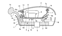
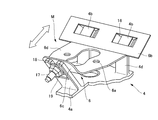
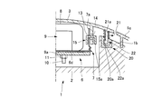
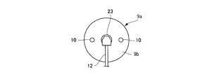
- FIG. 1 It is a disassembled perspective view which shows suitable one Embodiment of this invention. It is the structure of FIG. 1, Comprising: It is a sectional side view which shows the condition before attaching and fixing a mounting bracket. It is the structure of FIG. 1, Comprising: It is a sectional side view which shows the condition after attaching and fixing a mounting bracket. It is a perspective view which shows the mounting state of the mount part applied to the structure of FIG. 1, and a mounting bracket.
- FIG. 2 is a partial cross-sectional view showing the structure of FIG. 1 and an attachment structure between a cover and a bush. It is a bottom view which shows the attachment surface of the inflator main body in the structure of FIG.
- FIGS. 1 and 2 the present embodiment will be described taking an example in which the present embodiment is applied to a steering wheel 1.
- the metal core of the steering wheel 1 that is a component of the vehicle is formed mainly of a metal material.
- the steering wheel 1 has a boss 2 at the center.
- the boss 2 is connected to the steering shaft.
- the steering wheel 1 is usually provided with a cover 3 made of synthetic resin or the like that becomes a horn button.
- the cover 3 is arranged in the rim 1a of the steering wheel 1 so as to cover the boss portion 2 in an arrangement continuous with the design surface 1c of the spoke 1b (see FIG. 5).
- the outer shape of the cover 3 is formed so as to be continuous with the outer shape of the design surface 1c of the rim 1a and the spoke 1b.
- a mount portion 4 is formed on the boss portion 2, and a metal plate-like mounting bracket 6 is attached and fixed to the mount portion 4.
- the mount part 4 is provided in the boss
- the mounting bracket 6 is provided with a housing 7 on the upper surface facing the cover 3 side.
- the housing 7 is formed with an opening edge portion 7a that opens toward the cover 3, whereby the housing 7 is formed in a container shape.
- a folded airbag 8 and an inflator 9 attached to the airbag 8 are accommodated.
- the inflator 9 includes an inflator body 9a and a mounting bolt 10.
- the inflator body 9a that ejects the inflator gas is formed in a disk shape having a circular or polygonal planar outer contour and a low height.
- a plurality of gas ejection holes 24 are formed laterally along the circumferential direction on the peripheral side surface of the inflator body 9a.
- the inside of the inflator body 9a is filled with explosives that are rapidly burned when inflator gas is generated.
- the outer shell of the inflator body 9a is formed with a considerable strength that is not destroyed or scattered by the pressure of the explosive combustion action or the pressure of the inflator gas generated thereby. That is, the outer shell of the inflator body 9a is formed as a pressure vessel (pressure vessel) from a thick metal material.
- the inflator main body 9a provided with the pressure vessel is accommodated inside the airbag 8 that is expanded and inflated by the inflator gas.
- the airbag 8 is made of a fabric and formed in a bag shape as is well known in the art.
- the inflator body 9a is built in the bag-like airbag 8.
- the inflator body 9a has a mounting surface (bottom surface) 9b formed as a flat surface.
- the mounting surface 9b of the inflator body 9a faces the mounting bracket 6 that is mounted and fixed to the airbag installation portion via the airbag 8.
- the mounting bolt 10 is directly joined to the mounting surface 9b of the inflator body 9a directly by welding or the like.
- One end of the mounting bolt 10 is joined to the mounting surface 9b of the inflator body 9a, and protrudes downward from the mounting surface 9b so as to be fastened to the mounting bracket 6.
- the mounting bolt 10 is provided in an arrangement that fits within the planar outer contour of the inflator body 9a. In the illustrated example, two mounting bolts 10 are provided side by side, but the number of mounting bolts 10 is not limited to two.
- the center line BC in the bolt axial direction of each mounting bolt 10 is directed to the mounting surface 9b of the inflator body 9a.
- a straight line L connecting the positions where the center lines BC of the two attachment bolts 10 intersect the attachment surface 9b (hereinafter referred to as “intersection position”) is the attachment surface 9b of the inflator body 9a.
- the joint position of the mounting bolt 10 is set so as to pass through the center C.
- the straight line L connecting the intersection points is set in the left-right direction of the vehicle (vehicle width direction) in the case of a passenger seat airbag, and in the front-rear direction of the vehicle (length of the vehicle) in the case of a driver seat airbag. Is set to the vertical direction).
- an ignition device connection terminal 23 for connecting a harness 12 for inputting an ignition signal to the inflator 9 is provided on the mounting surface 9 b of the inflator body 9 a so as to be adjacent to the mounting bolt 10.
- the connection terminal 23 is disposed between the two mounting bolts 10.
- the connection terminal 23 is disposed at a position surrounded by the mounting bolts 10.
- the connection terminal 23 is disposed at the center of the mounting surface 9b, and the mounting bolt 10 is disposed on the outer peripheral side of the mounting surface 9b surrounding the center.
- the inflator main body 9a is stably fixed to the mounting bracket 6, and the connection terminal 23 is installed at the center of the mounting surface 9b, so that the harness Twelve connection work locations are integrated, and the connection terminals 23 are arranged in a space-saving manner.
- the center of the mounting surface 9b of the inflator body 9a is set to coincide with the vicinity of the center of the boss part 2.
- two bolt insertion holes 8 a are formed in the airbag 8 in order to project the two mounting bolts 10 joined to the inflator body 9 a housed inside the airbag 8.
- These bolt insertion holes 8 a are formed with a hole diameter slightly larger than the outer diameter of the mounting bolt 10 so that the mounting bolt 10 can be inserted.
- the airbag 8 is provided with a reinforcing structure that reinforces the bolt insertion hole 8a that is the only missing portion.
- the reinforcing structure for example, one to several reinforcing cloths 25 having bolt through holes 25a through which the mounting bolts 10 are passed are arranged around the bolt insertion holes 8a of the airbag 8, and the bolt through holes 25a are connected to the bolt insertion holes 8a. In accordance with the above, it is joined by sewing or the like.
- the reinforcing cloth 25 may be used in two sets, one set for each mounting bolt 10, or may be used with one set formed by a large external dimension extending over both of the two mounting bolts 10. Good.
- the airbag 8 incorporating the inflator body 9a is accommodated in the housing 7 as described above.
- the flat bottom surface 7c of the housing 7 is formed with a bolt hole 7b of the mounting bolt 10 protruding from the airbag 8, and the mounting bolt 10 is passed through the bolt hole 7b.
- the attachment surface 9 b of the inflator body 9 a is pressed against the bottom surface 7 c of the housing 7 through the airbag 8.
- the housing 7 is installed on the mounting bracket 6.
- Bolt holes 6a (see FIGS. 1 and 4) through which the mounting bolts 10 are inserted are formed in the mounting bracket 6, and the mounting bolts 10 are inserted through the bolt holes 6a.
- a nut 11 is screwed into the mounting bolt 10 inserted through the bolt hole 6a.
- the inflator body 9 a may be fixed to the housing 7 by fastening the mounting bolt 10 to the housing 7 with the nut 11. In this case, the housing 7 is separately joined to the mounting bracket 6.
- the inflator body 9 a is fixed to the mounting bracket 6 or the housing 7 by the fastening action of the mounting bolt 10. Due to the tension T generated in the mounting bolt 10 by this fastening action, the mounting surface 9b of the inflator body 9a presses and fixes the airbag 8 to the mounting bracket 6 or the bottom surface 7c of the housing 7.
- a plurality of holes 13 are formed in the opening edge 7 a of the housing 7 along the circumferential direction for attachment to the cover 3.
- a plurality of locking holes 14 are formed in the cover 3 according to the positions of the holes 13 of the housing 7.
- a metal connection bracket 15 is provided to connect the housing 7 to the cover 3.
- the connection bracket 15 is formed in a ring shape along the opening edge portion 7 a of the housing 7.
- the connecting bracket 15 is formed with a plurality of hooks 15 a in accordance with the positions of the locking holes 14 and the holes 13.
- Each hook 15 a of the connection bracket 15 is inserted into each hole 13 of the opening edge 7 a of the housing 7, and each hook 15 a inserted through each hole 13 is locked to each locking hole 14 of the cover 3.
- the opening edge 7 a of the housing 7 is connected to the cover 3 via the connection bracket 15.
- the housing 7 is configured to have a flexibility that can be deformed in accordance with the dimension between the mounting bracket 6 and the connecting bracket 15, and the dimension between the mounting bracket 6 and the cover 3.
- the housing 7 is provided with flexibility as follows.
- the housing 7 is made of, for example, a cloth woven from synthetic fibers, etc., and at least the height dimension from the mounting bracket 6 to the cover 3 is more flexible and flexible than that dimension. It is set to the given dimension.
- the housing 7 can be extended and contracted between the mounting bracket 6 and the cover 3, and the height dimension extending from the mounting bracket 6 to the cover 3 is more flexible and flexible. A bellows portion is formed.
- the housing 7 may be formed of a thin metal material or a synthetic resin material in addition to the cloth.
- the housing 7 is formed of an elastic material having elasticity.
- the housing 7 is formed of a spreadable material. In any of these, the housing 7 absorbs the variation in dimensions between the mounting bracket 6 and the cover 3.
- the mounting structure of the mounting bracket 6 to the mounting portion 4 will be described.
- the mounting portions 4 face each other and face the mounting bracket 6 and the cover 3 from the boss portion 2 side.
- the fixing portion 4a and the slope portion 4b that are formed by being raised are integrally formed.
- one fixing portion 4a is arranged at the position of the 6 o'clock direction on the steering wheel 1, and two slope portions are parallel to each other at the position of the 3 o'clock direction and the 9 o'clock direction. 4b is arranged.
- the slope portion 4b and the fixing portion 4a are formed in a narrow plate shape.
- Each slope part 4b is provided via the vertical wall part 4d with respect to the baseplate part 4c.
- a mount portion 4 forms a U-shaped or V-shaped mounting region M that narrows downward as viewed from the 3 o'clock or 9 o'clock direction. Is done.
- the mount portion 4 is configured by integrally forming one fixing portion 4a and two slope portions 4b formed in a plate shape on the bottom plate portion 4c.
- the mount portion 4 may be formed in the shape of a mortar having the fixing portion 4a and the slope portion 4b as “surfaces”.
- the mounting bracket 6 includes a slide portion 6b that is slidably engaged with the slope portion 4b of the mount portion 4, a mounting portion 6c that faces the fixing portion 4a, and a connecting portion 6d that connects the mounting portion 6c and the slide portion 6b. Is integrally formed.
- the lower surface of the slide portion 6b facing the slope portion 4b is formed along the slope of the slope portion 4b so as to be slidable with respect to the upper surface of the slope portion 4b.
- the mounting portion 6c facing the fixing portion 4a of the mount portion 4 is formed along the inclination of the fixing portion 4a so as to be in close contact with the fixing portion 4a. Accordingly, the mounting bracket 6 is also formed in a U shape or a V shape along the form of the mount portion 4 when viewed from the 3 o'clock direction or the 9 o'clock direction.
- the slide portion 6b is formed with a grip portion 16 for gripping the slope portion 4b in order to slidably engage the slide portion 6b with the slope portion 4b.
- the grip portion 16 is formed by integrally forming a U-shaped piece surrounding the slope portion 4b on the lower surface of the slide portion 6b that slides on the slope portion 4b.
- the means for slidably engaging the slide portion 6b with the slope portion 4b is not limited to the grip portion 16, but a dovetail slide groove formed along the slide direction on each of the slope portion 4b and the slide portion 6b and the slide. It may be a slide ridge that engages with the groove.
- Fastening members are provided on the mounting portion 6c of the mounting bracket 6 and the fixing portion 4a of the mount portion 4 to connect them.
- the fastening member is constituted by a bolt 17 inserted through the attachment portion 6c and the fixing portion 4a.
- a bolt insertion hole is formed in the mounting portion 6c, and a slot 18 is formed in the fixing portion 4a along the inclination direction of the slope portion 4b in order to insert the bolt 17 in an adjustable manner.
- a nut 19 is fastened from the lower surface side of the fixing portion 4a to the bolt 17 inserted into the bolt insertion hole of the fixing portion 4c and the fixing portion 4a and the slot 18, and thereby the fixing portion 4a and the fixing portion 6c are coupled.
- the mounting bracket 6 is supported and fixed stably at three points on the mount portion 4 by one fixing portion 4a and two slope portions 4b. Further, the mounting bracket 6 and the mount portion 4 are fixed only by the fastening operation of the single bolt 17.
- the bolt 17 is exemplified as the fastening member. However, any type of fastening member may be used as long as the mounting bracket 6 can be pulled and coupled to the mount portion 4.
- the cover 3 is attached to the mount portion 4 by the mounting bracket 6 via the housing 7 and the connection bracket 15, and can be pressed by the steering wheel 1 via an elastic member as shown in FIG. 5. Floating supported.
- the coil spring 21 is illustrated as an elastic member.
- Bush 20 is provided in the vicinity of each spoke 1b of steering wheel 1.
- the bush 20 is provided at three locations in the circumferential direction of the steering wheel 1.
- the coil spring 21 is provided between the bush 20 and the cover 3.
- a rod-shaped locking piece 22 projects from the cover 3 in accordance with the position of the bush 20.
- the locking piece 22 is movably penetrated through the hollow through hole 21a in the center of the coil spring 21.
- the locking piece 22 is moved downward by the pressing operation of the cover 3 and is moved upward by the restoring operation by the elastic force of the coil spring 21.
- a claw portion 22 a is formed at the lower end of each locking piece 22.
- the bush 20 is formed in a hollow box shape opened toward the locking piece 22 in order to allow movement of the locking piece 22.
- the bush 20 is formed with an engaging portion 20a that can be inserted into the locking piece 22 during assembly and that engages with the claw portion 22a of the locking piece 22 in order to prevent the locking piece 22 from being detached during use.
- the engaging portion 20a engages with a claw portion 22a that moves upward by the elastic force of the coil spring 21 to lock the cover 3 to the steering wheel 1, thereby positioning the restoring position of the cover 3 with respect to the steering wheel 1. Is done.
- the bush 20 is engaged with the locking pieces 22 of the cover 3 at three locations along the circumferential direction of the steering wheel 1, thereby positioning the cover 3 with respect to the rim 1 a.
- the locking piece 22 and the bush 20 may be provided at three or more locations.
- an airbag module in which various components are assembled in advance may be configured.
- the airbag module is configured by attaching at least the airbag 8 and the inflator 9 to the mount portion 4, the mounting bracket 6, the housing 7, the connection bracket 15, the cover 3, the bush 20, and the coil spring 21 in advance.
- the airbag module is attached and fixed to the mount portion 4 via the housing 7 and the attachment bracket 6, and the cover 3 and the like are attached to the airbag module via the connection bracket 15.
- the airbag module may be configured by attaching the cover 3 via the housing 7 and / or the attachment bracket 6 and the connection bracket 15 in advance.
- the operation of this embodiment will be described below.
- An example of the assembly procedure will be described.
- the airbag 8 and the inflator 9 are accommodated in the housing 7 to constitute an airbag module, and the housing 7 is attached to the mounting bracket 6 by using the mounting bolt 10 of the inflator body 9a. Can be fixed.
- the structure of the inflator 9 can be obtained by directly and integrally joining the mounting bolt 10 to the mounting surface 9b of the inflator body 9a.
- the inflator body 9a is accommodated in the airbag 8 in which the reinforcing cloth 25 is joined to the periphery of the bolt insertion hole 8a, and the mounting bolt 10 is moved from the bolt insertion hole 8a to the outside of the airbag 8. To protrude.
- the airbag 8 is accommodated in the housing 7 so that the mounting surface 9b of the inflator body 9a is pressed against the bottom surface 7c of the housing 7, and the mounting bolt 10 is protruded from the bolt hole 7b.
- an airbag module is constituted.
- the airbag module in which the mounting bracket 6 is fastened with the mounting bolt 10 is inserted into the mount region M in the steering wheel 1.
- the harness 12 is connected to the connection terminal 23.
- the slide portion 6b having the grip portion 16 is slidably engaged with the slope portion 4b, and the mounting portion 6c of the mounting bracket 6 is fixed to the fixing portion 4a of the mount portion 4 using the slide portion 6b.
- the fixing portion 4 a and the attachment portion 6 c are brought close to each other, the bolt 17 is inserted through the bolt insertion hole and the slot 18 and tightened with the nut 19.
- the slide portion 6b is engaged with the slope portion 4b more deeply by the fastening action of the nut 19.
- the movement of the position of the bolt 17 due to the movement of the slide portion 6 b is allowed by the slot 18.
- the airbag module is attached and fixed to the boss portion 2 of the steering wheel 1 via the mount portion 4.
- the bush 20 is disposed on the steering wheel 1.
- the hook 15a of the connection bracket 15 is inserted into the hole 13 of the opening edge 7a in the housing 7 of the airbag module.
- the hook 15 a is locked in the locking hole 14 of the cover 3.
- the cover 3 is attached to the mount portion 4 via the housing 7.
- the coil spring 21 is inserted into the locking piece 22 of the cover 3, the inserted coil spring 21 is disposed on the bush 20, and the cover 3 is pressed toward the bush 20.
- the claw portion 22 a of the locking piece 22 is engaged with the engaging portion 20 a of the bush 20.
- the cover 3 is attached to the steering wheel 1 while being positioned with respect to the restoring position and the rim 1a.
- the flexible housing 7 allows the cover 3 to move.
- the cover 3 may be attached to the housing 7 via the connecting bracket 15 at the stage of producing the airbag module, or each component may be attached to the cover 3 from the boss portion 2 side. You may make it attach in order toward the side.
- the mounting bolt 10 is directly joined to the mounting surface 9b of the inflator body 9a facing the mounting bracket 6 through the housing 7 so as to fit within the outer contour of the inflator body 9a. Since the mounting bolt 10 is passed through the housing 7 and can be fastened to the mounting bracket 6, the inflator 9 is fixed as compared with the case of mounting and fixing with a retainer or bracket that becomes large as in the background art.
- the boss portion 2 on the side is sufficient in a narrow space, and the mounting portion can be made compact.
- the inflator 9 can be directly attached to the mounting bracket 6, the man-hour for attaching the inflator 9 can be reduced.
- the mounting bolt 10 Since the mounting bolt 10 is directly and integrally joined to the mounting surface 9b of the disc-shaped inflator body 9a whose outer shell is formed of a pressure vessel, the retainer with the bolt can be eliminated and a vehicle airbag can be assembled. , Can reduce the weight. Further, the entire inflator body 9a having the mounting bolt 10 is accommodated in the airbag 8, and the airbag 8 can be fastened to the mounting bracket 6 together with the inflator body 9a by the mounting bolt 10. It can be securely and firmly fixed to the mounting bracket 6 that is fixedly attached to the bag installation portion, the reinforcing structure of the airbag 8 can be simplified, productivity can be improved and cost can be reduced, and ecology and resource saving can be achieved. Can contribute.
- the pressure vessel of the inflator main body 9a is strong against the pressure by the combustion action and the inflator gas pressure. Functions as a pressure vessel.
- the inflator body 9a composed of a rigid pressure vessel, the mounting bolt 10 directly and integrally joined to the inflator body 9a, the mounting bracket 6 fastened to the mounting bolt 10 and the airbag installation portion Unlike the mounting structure using a retainer with a bolt that is easily deformed as described above, the structure is highly integrated and rigid. Resist.
- the mounting bolts 10 are joined to the mounting surface 9b of the inflator main body 9a and are arranged at a clearly narrower interval than the bolt interval of the retainer with bolts, so that the attachment strength to the airbag installation portion is increased. be able to. Since the mounting surface 9b of the inflator main body 9a is pressed against the mounting bracket 6 side, the pressing area of the inflator main body 9a to the airbag installation portion can be expanded as compared with the case where the annular retainer is pressed.
- the mounting position of the mounting bolt 10 is set so that the straight line L connecting the center line (intersection position) BC of the mounting bolt 10 passes through the center C of the mounting surface 9b of the inflator body 9a,
- the mounting bolts 10 can be evenly arranged with good balance with respect to the mounting surface 9b. With this arrangement, pressure and gas pressure due to rapid combustion can be evenly distributed and transmitted to the mounting bracket 6 and the airbag installation portion, and the disk-shaped inflator body 9a tilts when the gas is ejected. A situation can be prevented and the airbag 8 can be appropriately inflated and inflated.
- the straight line L is set in the left-right direction of the vehicle, so that the deployment and inflation direction of the airbag 8 can be reliably directed toward the rear of the vehicle, and the operational stability of the airbag 8 can be improved.
- the straight line L is set in the longitudinal direction of the vehicle, the deployment and inflation direction of the airbag 8 can be reliably directed to the driver, and the operational stability of the airbag 8 can be improved.
- the inflator body 9a having a rigid pressure-resistant container is not easily deformed by connecting the inflator body 9a and the airbag installation portion with the mounting bolt 10 directly and integrally joined to the inflator body 9a.
- the mounting strength can be increased, the pressing area can be expanded, the distortion and deformation around the installation location of the inflator body 9a can be suppressed, and the pressure, gas pressure, and expansion pressure associated with the combustion action can be reduced. It can be received reliably and sufficiently.
- the area where the airbag 8 is pressed into the airbag installation part or the housing 7 can be expanded. Since the airbag 8 can be pressed and fixed to the airbag installation portion or the like over a wide range by the mounting surface 9b of the inflator body 9a, reinforcement of the airbag 8 can be reduced.
- the strength of the airbag 8 itself can be enhanced unlike the case of providing an opening that exposes the lower hemisphere of the inflator as in the background art. Since the strength of the airbag 8 can be increased in this way, sufficient reinforcement can be secured around the bolt insertion hole 8a by stacking one to several reinforcing cloths 25.
- the deployment and inflation performance of the airbag 8 can be appropriately ensured, and appropriate occupant protection performance can be ensured. Furthermore, since the retainer with a bolt can be abolished, weight reduction can be achieved.
- connection work locations of the harness 12 to the connection terminal 23 can be integrated, and the connection terminal 23 can be omitted. Can be arranged in space.
- the inflator body 9a By setting the position of the mounting bolt 10 to the outer peripheral edge side of the mounting surface 9b with respect to the position of the connecting terminal 23, the inflator body 9a can be stably fixed to the mounting bracket 6 and the connecting terminal is connected to the central portion of the mounting surface 9b. By installing 23, it is possible to consolidate connection work locations and save space.
- the inflator 9 that generates inflator gas can be appropriately supported by the steering shaft via the boss part 2.
- the operational stability of the airbag 8 can be improved.
- the boss portion 2 and the mount portion 4 of the steering wheel 1 constituting the airbag installation portion are connected to the cover 3.
- the housing 7 can absorb the dimensional tolerance and assembly tolerance of each part.
- the flexible housing 7 makes it possible to make the attachment to the boss portion 2 and the support of the cover 3 to the steering wheel 1 independent, and the dimensional tolerance of parts on the boss portion 2 side relative to the housing 7 In addition, it is possible to prevent the assembly tolerance from affecting the cover 3 side, and the dimensional tolerance and assembly tolerance of the parts closer to the cover 3 than the housing 7 from affecting the boss portion 2 side.
- the mounting and fixing to the boss portion 2 can be ensured, and at the same time, the installation position of the cover 3 that conceals the airbag 8 can be accurately aligned with the steering wheel 1. Therefore, for example, the design surface 1c position of the rim 1a and the spoke 1b of the steering wheel 1 and the installation position of the cover 3 can be aligned in series, and the appearance design can be improved. Further, the flexible housing 7 increases the flexibility of the mounting operation of the cover 3, and can improve the mounting operation between the locking piece 22 of the cover 3, the bush 20, and the coil spring 21.
- the mounting bracket 6 can be attached to the mount portion 4 by sliding movement using traction obtained by the fastening action of the bolt 17 and the nut 19, and a large number of bolts and nuts can be used as in the background art.
- the workability can be improved while the work for assembling the steering wheel 1 is a downward work, and the assembly tolerance is generated at the bolt fastening portion of the fixing part 4a and the mounting part 6c. As a result, the reliability of the assembly work can be improved.
- the flexible housing 7 moves the mounting bracket 6 downward from the cover 3 side toward the boss portion 2 side. It can be tolerated, can be fitted to the assembling work by the slide operation, and can be attached appropriately and reliably.
- the mount portion 4 forms a mount region M that gradually narrows from the cover 3 side toward the boss portion 2 side, including the fixing portion 4a, at least by the slope portion 4b. 4 can be guided toward the center of the steering wheel 1, and even the small-diameter steering wheel 1 can perform the work accurately and quickly, and can automate the assembly work. can do.
- the position of the bolt 17 can be adjusted by adapting to the procedure of sliding the slide portion 6b to the slope portion 4b, and the mounting bracket 6 is mounted on the mount portion 4 Can be mounted and fixed accurately.
- the grip portion 16 that grips and engages the slope portion 4a is formed on the slide portion 6b, the slide movement of the slide portion 6b with respect to the slope portion 4a can be stabilized.
- the fixing bracket 6 Since the fixing bracket 6 is supported at three points by the one fixing portion 4a and the two slope portions 4b, the airbag 8 that expands and inflates and the inflator 9 that explodes and ejects the inflator gas can be reliably supported. . Since the mount portion 4 and the mounting bracket 6 are fastened by the single bolt 17, the fastening work location can be made one place, and the assembly work can be simplified.
- the cover 3 is formed with the locking hole 14, the housing 7 is formed with the hole 13, and the connecting bracket 15 is formed with the hook 15 a that is inserted into the hole 13 and locked into the locking hole 14.
- the housing 7 can be connected to the cover 3 with extremely simple and good workability, and the assembling work can be simplified.
- Assembling workability can be simplified by assembling an airbag module by assembling at least the airbag 8 and the inflator 9.
- the assembly workability can be further simplified by constructing the airbag module by further incorporating the cover 3, the connecting bracket 15, the housing 7, and / or the mounting bracket 6.
- the structure of the airbag device for the driver's seat has been described by using the boss portion 2 and the mount portion 4 of the steering wheel 1 as the airbag installation portion.
- a passenger seat airbag device, a rear seat airbag device, a curtain airbag device, a seat having a steering support member or the like as an airbag installation portion and a lid of an instrument panel as a cover instead of this form, for example, a passenger seat airbag device, a rear seat airbag device, a curtain airbag device, a seat having a steering support member or the like as an airbag installation portion and a lid of an instrument panel as a cover.
- any airbag device such as an airbag device incorporated in a back or seat cushion.
- FIG. 9 shows a modification of the above embodiment.
- This modification is a case where three or more mounting bolts 10 are provided on the mounting surface 9b of the inflator body 9a.
- the center line BC in the bolt axial direction of each mounting bolt 10 is directed to the mounting surface 9b of the inflator body 9a.
- the mounting surface 9b of the inflator body 9a is drawn by connecting the intersections of a plurality of mounting bolts 10 in the circumferential direction along the outer contour of the mounting surface 9b, in the illustrated example, in the circumferential direction.
- the mounting position of the mounting bolt 10 is set so that the center of gravity G of the polygon Q to be aligned matches the center position C of the mounting surface 9b of the inflator body 9a.
- the mounting bolts 10 can be arranged in a balanced manner with respect to the mounting surface 9b of the inflator body 9a. Therefore, the airbag 8 can be appropriately deployed and inflated as in the above embodiment.
- the mounting bolts 10 are arranged on the mounting surface 9 b of the inflator body 9 a on the vehicle front side. It is preferable that the number of installations does not fall below the number of installations on the vehicle rear side. In this way, the inflator body 9a can be firmly fixed toward the rear of the vehicle, the deployment and inflation direction of the airbag 8 can be reliably directed toward the rear of the vehicle, and the operational stability of the airbag 8 can be improved. Can be improved.
- the present invention is not limited to the detailed shape, size, configuration, and the like of the components shown in the accompanying drawings unless otherwise stated in the present specification.
- the attachment surface 9b (joint location) of the inflator body 9a to which the attachment bolt 10 is joined is not limited to a flat surface but may be a spherical surface or a curved surface.
- expressions and terms used in the present specification are for the purpose of explanation, and are not limited thereto unless otherwise specified.
Landscapes
- Engineering & Computer Science (AREA)
- Mechanical Engineering (AREA)
- Air Bags (AREA)
Abstract
【課題】インフレータの取り付けに供されるエアバッグ設置部が狭いスペースで足り、コンパクト化を達成することが可能であると共に、取付工数の低減が可能な車両用エアバッグモジュールを提供する。 【解決手段】車両用エアバッグのインフレータ構造は、外殻がプレッシャーベッセルで形成され、ボルト挿通孔8aが形成されたエアバッグ8内部に全体が収容されるディスク形状のインフレータ本体9aと、インフレータ本体9aの取付面9bに直接一体的に接合され、ボルト挿通孔8aからエアバッグ8外方へ突出されて、車両のエアバッグ設置部側の取付ブラケット6に締結可能な取付ボルト10とを備えた。
Description
本発明は、インフレータの取り付けに供されるエアバッグ設置部が狭いスペースで足り、コンパクト化を達成することが可能であると共に、取付工数の低減が可能な車両用エアバッグのインフレータ構造、エアバッグモジュールおよびエアバッグ構造に関する。
また、本発明は、ボルト付きのリテーナを廃止して車両用エアバッグを組み立てることが可能であって、重量を軽減することができると共に、エアバッグをエアバッグ設置部に健全かつ強固に固定することが可能で、当該エアバッグの構造簡素化、生産性向上、並びにコスト低減を達成でき、エコロジーや省資源化に資する車両用エアバッグのインフレータ構造、エアバッグモジュールおよびエアバッグ構造に関する。
エアバッグを車両に取り付ける構造として、例えば特許文献1及び特許文献2が知られている。特許文献1の「ステアリング装置」は、車両に搭載されるステアリング装置において、ディスク形状のインフレータをリテーナーに取り付け、リテーナーを芯金上に取付固定している。
特許文献2の「エアバッグ装置」は、エアバッグ本体とインフレータとを有するエアバッグモジュールを、取付具を介してリインフォースメントに取り付けたエアバッグ装置であって、前記取付具は、前記エアバッグモジュールの収容ケースと、前記エアバッグモジュール及び前記収容ケースを支持して固定する脚部を有したブラケットと、前記収容ケースの底部から突出した突出部材とを備えている。また、前記ブラケットの前記脚部は傾斜部を有し、前記突出部材は、前記収容ケースが衝撃を受けて前記ブラケットを変形させるときに、前記脚部の前記傾斜部を押圧して前記ブラケットの変形を補助するように構成されている。
従来、一般的には、ディスク形状のインフレータは、特許文献1のように、エアバッグを収容するリテーナや、別途ブラケットを利用して、ステアリングホイールの芯金に取り付けられている。リテーナやブラケットには、インフレータを装着する装着スペースが設定され、この装着スペースの外回りに、ステアリングホイールへの取付用ボルトなどの取り付け手段が配置される。従って、インフレータの外形寸法に比べて、リテーナやブラケット自体大型になると共に、これらが取り付けられるステアリングホイールの芯金部分を広いスペースで設定しなければならないという課題があった。
また、取付工数に関し、インフレータをリテーナ等に装着し、その後、リテーナ等を芯金に取り付ける作業が必要であり、煩雑であった。
当該問題は、ステアリングホイールに設置されるエアバッグモジュールに限らず、助手席用エアバッグ装置等、その他の箇所に設置されるエアバッグ装置にあっても同様であった。
特許文献2では、インフレータは取付用のフランジを有している。フランジは、エアバッグ本体内部に収容される枠体状のリテーナのボルトを利用して、当該リテーナ、エアバッグ本体、エアバッグを収容する収容ケース、並びにブラケットに、ナットで結合する。車両側固定部位であるリインフォースメントに固定部を設け、この固定部にブラケットを介して、インフレータやエアバッグ本体等を固定する。
インフレータは、リテーナに取り囲まれる上半球部がエアバッグ本体内部に収容されると共に、下半球部が、エアバッグ本体及び収容ケースの開口部から突出して、それらの外部に露出される。
インフレータは、火薬の急速な燃焼によりインフレータガスを発生する。インフレータは、急速燃焼作用で衝撃を発生する。従って、インフレータは、リインフォースメントに強固に支持固定する必要がある。インフレータをリインフォースメントで強固に支持固定するため、インフレータのフランジに通したリテーナのボルトで、リインフォースメント側との結合を確保していた。このため、特許文献2の構造では、ボルト付きのリテーナが必須であった。ボルト付きのリテーナが必要なため、重量が重くなるという課題があった。
エアバッグ本体には、インフレータの下半球部が露出する大きな開口部が形成されている。リテーナは、インフレータのフランジ及びエアバッグ本体の開口部周辺を収容ケース側へ押さえ込んで、当該開口部を補強する。しかし、リテーナは、開口部の外周縁を環状に押さえ込む程度であり、押さえ込み面積が狭く、エアバッグ本体の開口部周辺を十分に補強することはできなかった。また、リテーナは、インフレータを取り囲む枠体状であるため、強度不足であり、インフレータでの急速燃焼作用による衝撃やエアバッグ本体の膨張圧力で、容易に変形してしまう。
要するに、リテーナによる開口部周辺の補強は、エアバッグ本体を押さえ込む面積が狭く、かつ簡単に変形してしまうために、十分ではなかった。このため、エアバッグ本体の開口部周りの補強を強化するために、開口部周りに多数の布片を重ね合わせて縫合するなど、エアバッグ本体自体で開口部周辺を堅牢に補強する必要があった。この補強のために、エアバッグ本体の構造が複雑化し、エアバッグ本体の製造に手間がかかり、製品のコストアップを招いていた。
本発明は、インフレータの取り付けに供されるエアバッグ設置部が狭いスペースで足り、コンパクト化を達成することが可能であると共に、取付工数の低減が可能な車両用エアバッグのインフレータ構造、エアバッグモジュールおよびエアバッグ構造を提供することを目的とする。
また本発明は、ボルト付きのリテーナを廃止して車両用エアバッグを組み立てることが可能であって、重量を軽減することができると共に、エアバッグクッションを車両側固定部位に健全かつ強固に固定することが可能で、当該エアバッグクッションの構造簡素化、生産性向上、並びにコスト低減を達成でき、エコロジーや省資源化に資する車両用エアバッグのインフレータ構造、エアバッグモジュールおよびエアバッグ構造を提供することを目的とする。
本発明にかかる車両用エアバッグのインフレータ構造は、外殻がプレッシャーベッセルで形成され、ボルト挿通孔が形成されたエアバッグ内部に全体が収容されるディスク形状のインフレータ本体と;該インフレータ本体の取付面に直接一体的に接合され、該ボルト挿通孔から該エアバッグ外方へ突出されて、車両のエアバッグ設置部に締結可能な取付ボルトとを備えたことを特徴とする。
該インフレータ本体の該取付面は、該エアバッグ設置部への締結で該取付ボルトに発生するテンションにより、該エアバッグを該エアバッグ設置部に押圧して固定することが好ましい。
該取付ボルトは2本備えられ、各取付ボルトの接合位置は、該インフレータ本体の該取付面において、これら取付ボルトの中心線を結ぶ直線が当該取付面の中心を通過するように設定されることが望ましい。
助手席用エアバッグの場合、該取付ボルトの中心線を結ぶ直線が、車両の左右方向に設定されることが好ましい。運転席用エアバッグの場合、該取付ボルトの中心線を結ぶ直線が、車両の前後方向に設定されることが望ましい。
該取付ボルトは3本以上備えられ、各取付ボルトの接合位置は、該インフレータ本体の該取付面において、該インフレータ本体の外形輪郭に沿う周方向にこれら取付ボルトの中心線を結んで描かれる多角形の重心が当該取付面の中心に合致するように設定されることが好ましい。
該取付ボルトは、該インフレータ本体の該取付面において、車両前方側の設置数が車両後方側の設置数を下回らないことが望ましい。
該インフレータ本体の該取付面に、該取付ボルトと隣接させて点火装置用接続端子を設けることが好ましい。
本発明にかかる車両用エアバッグモジュールは、上記車両用エアバッグのインフレータ構造を備え;該取付ボルトが接合された該インフレータ本体と;該取付ボルトを挿通する該ボルト挿通孔が形成され、該インフレータ本体を内部に収容するエアバッグとを備えたことを特徴とする。
さらに、該車両のエアバッグ設置部に取付固定される取付ブラケットを備え;該インフレータ本体の該取付面は、該取付ブラケットに対面し;該取付面に接合した該取付ボルトは、該インフレータ本体と共に該エアバッグを該取付ブラケットに締結可能であることが好ましい。
本発明にかかる車両用エアバッグ構造は、上記車両用エアバッグモジュールを車両のエアバッグ設置部に設置する車両用エアバッグ構造であって;該エアバッグ設置部には、互いに向かい合わせて、定着部及びスロープ部を形成し;少なくとも該スロープ部を、該定着部に向かって傾斜させて形成して、該定着部との間に次第に狭まるマウント領域を形成し;該車両用エアバッグモジュールを該取付ボルトで締結した取付ブラケットには、該スロープ部にスライド移動自在に係合するスライド部及び該定着部に向かい合う取付部を形成し;該取付ブラケットの該取付部を該エアバッグ設置部の該定着部に、締結作用により該スライド部を介して該取付部を該定着部へ向かって牽引する締結部材で結合することを特徴とする。
さらに、車両に取り付けられ、該エアバッグ設置部を覆うカバーと、該エアバッグを内部に収容し、該取付ブラケット上に設置されるハウジングとを備え;該ハウジングには、該カバーに向かって開口する開口縁部が形成され;該ハウジングの該開口縁部と該カバーは、連結ブラケットで連結され;該ハウジングは、該取付ブラケットと該カバーとの間の寸法に応じて変形自在な柔軟性を有することが好ましい。
さらに、該車両用エアバッグモジュールが該ハウジングを含み;該取付ボルトを、該ハウジングを介して該取付ブラケットに締結することで、該インフレータ本体を該エアバッグ設置部に固定することが望ましい。
本発明にあっては、インフレータの取り付けに供されるエアバッグ設置部が狭いスペースで足り、コンパクト化を達成することができると共に、取付工数を低減することができる。
また、本発明にあっては、ボルト付きのリテーナを廃止して車両用エアバッグを組み立てることができ、重量を軽減することができると共に、エアバッグクッションを車両側固定部位に健全かつ強固に固定することができ、当該エアバッグクッションの構造簡素化、生産性向上、並びにコスト低減を達成できて、エコロジーや省資源化に資することができる。
以下に、本発明の好適な実施形態を、添付図面を参照して詳細に説明する。図1及び図2に示すように、本実施形態は、ステアリングホイール1に適用した場合を例にとって説明される。車両の構成部品であるステアリングホイール1の芯金は金属材料を主体として形成される。ステアリングホイール1は、中央部にボス部2を有する。ボス部2は、ステアリングシャフトに連結される。
ステアリングホイール1には通常、ホーンボタンとなる合成樹脂製等のカバー3が設けられる。カバー3は、ステアリングホイール1のリム1a内に、スポーク1bの意匠面1cと連なる配置で、ボス部2を覆って配置される(図5参照)。カバー3の外形形態は、リム1aやスポーク1bの意匠面1cの外形形状と連なるように形成される。
ボス部2には、マウント部4が形成され、マウント部4には、金属製のプレート状の取付ブラケット6が取付固定される。本実施形態では、ステアリングホイール1のボス部2にマウント部4を設けて、エアバッグ設置部が構成されている。取付ブラケット6のマウント部4への取付構造は、追って詳述する。
取付ブラケット6には、カバー3側に面する上面に、ハウジング7が設けられる。ハウジング7には、カバー3に向かって開口する開口縁部7aが形成され、これによりハウジング7は容器状に形成される。ハウジング7の内部には、折り畳んだエアバッグ8と、エアバッグ8に装着したインフレータ9が収容される。
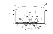
図7及び図8に示すように、インフレータ9は、インフレータ本体9aと、取付ボルト10を含む。インフレータガスを噴出するインフレータ本体9aは、平面外形輪郭が円形状もしくは多角形状で、高さが低いディスク形状に形成される。インフレータ本体9aの周側面には、周方向に沿って、複数のガス噴出孔24が横向きに形成される。
インフレータ本体9aの内部には、インフレータガスを発生させる際に急速燃焼される火薬が充填されている。インフレータ本体9aの外殻は、従来周知のように、火薬の燃焼作用による圧力やそれによって発生するインフレータガスの圧力で破壊・飛散することのない、相当の強度で形成されている。すなわち、インフレータ本体9aの外殻は、肉厚な金属材料により、プレッシャーベッセル(耐圧容器)として形成されている。
プレッシャーベッセルを備えたインフレータ本体9aは、全体がインフレータガスで展開膨張するエアバッグ8内部に収容される。エアバッグ8は、従来周知のように、ファブリック製で、袋状に形成されている。インフレータ本体9aは、袋状のエアバッグ8に内蔵される。
インフレータ本体9aは、取付面(底面)9bが平坦面で形成される。インフレータ本体9aの取付面9bは、エアバッグ8を介して、エアバッグ設置部に取付固定される取付ブラケット6に対面する。インフレータ本体9aの取付面9bには直接、取付ボルト10が溶接などにより、一体的に接合される。取付ボルト10は、一端がインフレータ本体9aの取付面9bに接合され、取付ブラケット6と締結可能に、当該取付面9bから下方へ向かって突出される。取付ボルト10は、インフレータ本体9aの平面外形輪郭内に納まる配置で設けられる。図示例にあっては、取付ボルト10は、2本並設されているが、取付ボルト10の本数は2本に限られない。
取付ボルト10が2本の場合、各取付ボルト10のボルト軸方向の中心線BCは、インフレータ本体9aの取付面9bに向かう。インフレータ本体9aの取付面9bにおいて、これら2本の取付ボルト10の中心線BCが取付面9bと交わる位置(以下、「交点位置」という)を結ぶ直線Lが、当該インフレータ本体9aの取付面9bの中心Cを通過するように、取付ボルト10の接合位置が設定される。交点位置を結ぶ直線Lは、助手席用エアバッグの場合には、車両の左右方向(車両の幅方向)に設定され、運転席用エアバッグの場合には、車両の前後方向(車両の長さ方向)に設定される。
インフレータ本体9aの取付面9bには図6に示すように、取付ボルト10と隣接させて、インフレータ9に点火信号を入力するハーネス12を接続するための点火装置用接続端子23が設けられる。図示例にあっては、2本の取付ボルト10の間に、接続端子23が配設される。このように取付ボルト10が複数本である場合には、接続端子23は、取付ボルト10で取り囲まれる位置に設けられる。具体的には、接続端子23は取付面9bの中央部に配置され、中央部を取り囲む取付面9bの外周縁側に、取付ボルト10が配置される。
取付ボルト10位置を取付面9bの外周縁側に設定することで、インフレータ本体9aは取付ブラケット6に安定的に固定されると共に、取付面9bの中央部に接続端子23を設置することで、ハーネス12の接続作業箇所が集約化され、かつ、接続端子23が省スペースで配置される。
また、インフレータ本体9aの取付面9bの中心は、ボス部2の中心付近に一致するように設定される。これにより、インフレータガスを発生するインフレータ本体9aを、ボス部2を介してステアリングシャフトに適切に支持させることができ、エアバッグ8の作動安定性が向上される。
エアバッグ8には図7に示すように、内部に収容したインフレータ本体9aに接合した2つの取付ボルト10をエアバッグ8外方へ突出させるために、2つのボルト挿通孔8aが形成される。これらボルト挿通孔8aは、取付ボルト10を挿通し得るように、当該取付ボルト10の外径よりも僅かに大きな孔径で形成される。エアバッグ8には、唯一の欠損部となるボルト挿通孔8aを補強する補強構造が備えられる。
補強構造としては例えば、取付ボルト10を通すためのボルト通し孔25aを有する一枚から数枚の補強布25を、エアバッグ8のボルト挿通孔8a周辺に、ボルト通し孔25aをボルト挿通孔8aに合わせて、縫合などにより接合する。補強布25は、各取付ボルト10それぞれに1セットずつで、2セット用いてもよいし、あるいは2本の取付ボルト10両方に亘る大きな外形寸法で形成して、1セットで用いるようにしてもよい。
インフレータ本体9aを内蔵したエアバッグ8は上述したように、ハウジング7に収容される。ハウジング7の平坦な底面7cには、エアバッグ8から突出する取付ボルト10のボルト孔7bが形成され、このボルト孔7bに取付ボルト10が貫通される。この際、エアバッグ8を介して、インフレータ本体9aの取付面9bがハウジング7の底面7cに押し当てられる。
ハウジング7は取付ブラケット6上に設置される。取付ブラケット6には、取付ボルト10を挿通するボルト孔6a(図1および図4参照)が形成され、このボルト孔6aに取付ボルト10が挿通される。ボルト孔6aに挿通された取付ボルト10には、ナット11が螺合される。取付ボルト10にナット11を螺合することにより、ハウジング7が取付ブラケット6と締結固定され、またハウジング7に収容したエアバッグ8が、内部のインフレータ本体9aと共に、締結固定される。
取付ボルト10を、ハウジング7にナット11で締結することにより、インフレータ本体9aをハウジング7に固定するようにしてもよい。この場合、ハウジング7は別途、取付ブラケット6に接合される。
いずれにしても、取付ボルト10による締結作用で、インフレータ本体9aを取付ブラケット6もしくはハウジング7に固定する。この締結作用で取付ボルト10に発生するテンションTによって、インフレータ本体9aの取付面9bは、エアバッグ8を取付ブラケット6やハウジング7の底面7cに押圧して固定する。
ハウジング7の開口縁部7aには、カバー3への取り付けのために、周方向に沿って複数の孔部13が形成される。カバー3には、ハウジング7の孔部13位置に合わせて、複数の係止孔14が形成される。これらカバー3とハウジング7との間には、ハウジング7をカバー3に連結するために、金属製の連結ブラケット15が設けられる。本実施形態にあっては、連結ブラケット15は、ハウジング7の開口縁部7aに沿って、リング状に形成される。
連結ブラケット15には、係止孔14及び孔部13の位置に合わせて、複数のフック15aが形成される。連結ブラケット15の各フック15aは、ハウジング7の開口縁部7aの各孔部13に挿通され、各孔部13に挿通された各フック15aがカバー3の各係止孔14に係止されることで、連結ブラケット15を介して、ハウジング7の開口縁部7aがカバー3に連結される。
ハウジング7は、取付ブラケット6と連結ブラケット15との間の寸法、ひいては取付ブラケット6とカバー3との間の寸法に応じて変形自在な柔軟性を有するように構成される。ハウジング7には例えば、以下のようにして、柔軟性が備えられる。
第1には、ハウジング7は、例えば合成繊維等で織った布製とされ、少なくとも取付ブラケット6からカバー3に亘る高さ寸法に対し、当該寸法よりもゆとりがあって融通が利く、延び代を持たせた寸法に設定される。第2には、ハウジング7に、取付ブラケット6とカバー3との間で伸縮自在であって、取付ブラケット6からカバー3に亘る高さ寸法に対し、当該寸法よりもゆとりがあって融通が利く蛇腹部分が形成される。この場合、ハウジング7は、上記布製の他、薄板状の金属材や合成樹脂材で形成してもよい。第3には、ハウジング7は、伸縮性を有する弾性素材で形成される。第4には、ハウジング7は、展延性素材で形成される。これらいずれにあっても、ハウジング7により、取付ブラケット6とカバー3との間の寸法のバラツキが吸収される。
取付ブラケット6のマウント部4への取付構造について説明すると、図2から図4に示すように、マウント部4は、互いに向かい合わせて、ボス部2側から取付ブラケット6やカバー3側に向かって立ち上げて形成された定着部4a及びスロープ部4bが一体成形されて構成される。本実施形態にあっては、ステアリングホイール1における6時の方向の位置に定着部4aが一つ配置されると共に、3時の方向と9時の方向の位置に互いに平行に、二つのスロープ部4bが配置される。これらスロープ部4b及び定着部4aは、幅狭な板状に形成される。各スロープ部4bは、底板部4cに対し、縦壁部4dを介して設けられる。
これらスロープ部4bは、ボス部2上方に、カバー3側からボス部2側へ向かって次第に狭まるマウント領域Mを形成するために、定着部4aへ向かって傾斜させて形成される。定着部4aも、ボス部2上方に、カバー3側からボス部2側へ向かって次第に狭まるマウント領域Mを形成するために、スロープ部4bへ向かって傾斜させて形成される。従って、ステアリングホイール1のボス部2上には、マウント部4により、3時の方向もしくは9時の方向から見て、下方へ向かって窄まるU字状もしくはV字状のマウント領域Mが形成される。
本実施形態にあっては、マウント部4は、板状に形成した一つの定着部4a及び二つのスロープ部4bを底板部4cに一体成形して構成されている。しかしながら、マウント部4は、これら定着部4aやスロープ部4bを「面」として備える、すり鉢状の形態で形成しても良いことはもちろんである。
取付ブラケット6は、マウント部4のスロープ部4bにスライド移動自在に係合するスライド部6bと、定着部4aに向かい合う取付部6cと、これら取付部6c及びスライド部6bを連結する連結部6dとが一体成形されて構成される。スロープ部4bに面するスライド部6bの下面は、スロープ部4bの上面に対しスライド移動自在とするために、当該スロープ部4bの傾斜に沿って形成される。また、マウント部4の定着部4aに面する取付部6cは、定着部4aに密着し得るように、当該定着部4aの傾斜に沿って形成される。従って、取付ブラケット6も、3時の方向もしくは9時の方向から見て、マウント部4の形態に沿ったU字状もしくはV字状に形成される。
本実施形態にあっては、スライド部6bには、当該スライド部6bをスロープ部4bにスライド自在に係合させるために、スロープ部4bを把持するグリップ部16が形成される。グリップ部16は、スロープ部4bを取り囲むU字片を、スロープ部4b上をスライド移動するスライド部6bの下面に一体形成して構成される。スライド部6bをスロープ部4bにスライド自在に係合させる手段としては、グリップ部16に限らず、スロープ部4b及びスライド部6bそれぞれにスライド方向に沿って形成した蟻溝状のスライド溝及び当該スライド溝に係合するスライド突条であってもよい。
取付ブラケット6の取付部6cとマウント部4の定着部4aには、これらを結合する締結部材が設けられる。本実施形態にあっては、締結部材は、取付部6c及び定着部4aに挿通されるボルト17で構成される。取付部6cには、ボルト挿通孔が形成されると共に、定着部4aには、ボルト17を位置調整可能に挿通するために、スロープ部4bの傾斜方向に沿ってスロット18が形成される。取付部6c及び定着部4aのボルト挿通孔及びスロット18に挿通されたボルト17には、定着部4aの下面側からナット19が締結され、これにより定着部4aと取付部6cが結合される。
ボルト17で締結する際、この締結作用によって、スライド部6bを介して取付ブラケット6全体がスロープ部4bに対しスライド移動し、取付部6cが定着部4aへ向かって牽引される。この牽引作用によって、スライド部6bがスロープ部4bに深く係合されるととともに、ボルト17で取付部6cが定着部4aに結合され、これにより取付ブラケット6は、マウント部4にしっかりと取付固定される。
取付ブラケット6は、一つの定着部4aと二つのスロープ部4bにより、マウント部4に三点支持されて安定的に固定される。また、取付ブラケット6とマウント部4とは、単一のボルト17の締結作業のみで、固定される。本実施形態にあっては、締結部材としてボルト17を例示したが、取付ブラケット6を牽引してマウント部4に結合できるものであれば、どのような形態の締結部材であってもよい。
カバー3は上述したように、ハウジング7及び連結ブラケット15を介して、取付ブラケット6によりマウント部4に取り付けられる一方で、図5に示すように、ステアリングホイール1に弾性部材を介して押圧操作可能にフローティング支持される。本実施形態では、弾性部材として、コイルスプリング21が例示されている。
ステアリングホイール1の各スポーク1b付近には、ブッシュ20が設けられる。ブッシュ20は例えば、ステアリングホイール1の周方向に3箇所設けられる。コイルスプリング21は、ブッシュ20とカバー3との間に設けられる。カバー3には、ブッシュ20位置に合わせて、ロッド状の係止片22が突設される。係止片22は、コイルスプリング21中央の中空貫通孔21aに移動自在に貫通される。係止片22は、カバー3が押圧操作されることで下向きに移動され、コイルスプリング21の弾発力による復原動作で上向きに移動される。各係止片22の下端には、爪部22aが形成される。
ブッシュ20は、係止片22の移動を許容するために、係止片22に向かって開口された中空ボックス状に形成される。ブッシュ20には、組立時に係止片22を挿入でき、使用時に係止片22が離脱するのを防止するために、係止片22の爪部22aに係合する係合部20aが形成される。係合部20aは、コイルスプリング21による弾発力で上向きに移動する爪部22aに係合してカバー3をステアリングホイール1に係止し、これによりステアリングホイール1に対するカバー3の復原位置が位置決めされる。また、ブッシュ20は、ステアリングホイール1の周方向に沿って、カバー3の係止片22と3箇所で係合され、これによりリム1aに対するカバー3位置が位置決めされる。係止片22及びブッシュ20は、3箇所以上設けても良いことはもちろんである。
以上説明した本実施形態に関し、ステアリングホイール1に各部品を個々に取り付けることに代えて、各種部品を予め組み付けたエアバッグモジュールを構成するようにしてもよい。例えばエアバッグモジュールは、マウント部4や取付ブラケット6、ハウジング7、連結ブラケット15、カバー3、ブッシュ20、コイルスプリング21に対し、少なくともエアバッグ8およびインフレータ9を予め取り付けて構成される。このエアバッグモジュールが、ハウジング7、取付ブラケット6を介してマウント部4に取付固定されると共に、このエアバッグモジュールに連結ブラケット15を介してカバー3等が取り付けられる。エアバッグモジュールには、予めハウジング7および/または取付ブラケット6、連結ブラケット15を介してカバー3を取り付けて構成してもよい。
本実施形態の作用について、以下に説明する。組立手順の一例について説明すると、エアバッグ8及びインフレータ9をハウジング7内に収容してエアバッグモジュールを構成し、インフレータ本体9aの取付ボルト10を利用することで、ハウジング7を取付ブラケット6に取付固定することができる。
まず、インフレータ9の構造自体は、インフレータ本体9aの取付面9bに取付ボルト10を直接一体的に接合することで得られる。
エアバッグモジュールの組立について説明すると、まず、補強布25をボルト挿通孔8a周辺に接合したエアバッグ8内部に、インフレータ本体9aを収容し、取付ボルト10をボルト挿通孔8aからエアバッグ8外方へ突出させる。次いで、インフレータ本体9aの取付面9bをハウジング7の底面7cに押し当てるようにして、エアバッグ8をハウジング7内に収容し、取付ボルト10をボルト孔7bから突出させる。これにより、エアバッグモジュールが構成される。
取付ブラケット6上にハウジング7を設置し、取付ボルト10にナット11を螺合して、当該取付ボルト10を取付ブラケット6に締結すると、取付ボルト10にテンションTが発生する。このテンションTにより、インフレータ本体9aの取付面9bは、取付ブラケット6及びハウジング7に向かって牽引されることとなり、エアバッグ8を取付ブラケット6等に押圧して固定することができる。
次いで、取付ブラケット6が取付ボルト10で締結されたエアバッグモジュールを、ステアリングホイール1内のマウント領域Mに挿入する。この際、接続端子23にハーネス12を接続する。
エアバッグモジュールを挿入したら、グリップ部16を有するスライド部6bをスロープ部4bにスライド移動自在に係合し、スライド部6bを利用して取付ブラケット6の取付部6cをマウント部4の定着部4aに接近させる。定着部4aと取付部6cとを近接させたら、ボルト挿通孔及びスロット18に亘ってボルト17を挿通し、ナット19で締め付けていく。
この締結段階では、ナット19による締結作用でスライド部6bがより深くスロープ部4bに係合していく。スライド部6bの移動によるボルト17位置の移動は、スロット18によって許容される。ボルト17へのナット19の締結が完了することで、エアバッグモジュールは、マウント部4を介して、ステアリングホイール1のボス部2に取付固定される。
次いで、ステアリングホイール1にブッシュ20を配設する。これと併せて、エアバッグモジュールのハウジング7には、開口縁部7aの孔部13に連結ブラケット15のフック15aが挿通される。その後、フック15aをカバー3の係止孔14に係止する。これにより、ハウジング7を介して、カバー3がマウント部4に取り付けられる。
カバー3の係止片22にコイルスプリング21を挿入し、挿入したコイルスプリング21をブッシュ20上に配置し、カバー3をブッシュ20に向かって押し付ける。この押し付けにより、係止片22の爪部22aがブッシュ20の係合部20aに係合される。これにより、カバー3は、ステアリングホイール1に、復原位置、並びにリム1aに対する位置決めがなされて、取り付けされる。カバー3の押圧操作時には、柔軟性を有するハウジング7がカバー3の移動を許容する。
上記組立手順は一例であって、エアバッグモジュールを作成する段階で、ハウジング7に連結ブラケット15を介してカバー3を取り付けておいても良いし、あるいは、各部品をボス部2側からカバー3側に向かって順番に取り付けていくようにしてもよい。
以上説明した本実施形態にあっては、ハウジング7を介して取付ブラケット6に対面するインフレータ本体9aの取付面9bに、インフレータ本体9aの外形輪郭内に納める配置で、取付ボルト10を直接接合し、この取付ボルト10を、ハウジング7を貫通させて取付ブラケット6に締結可能としたので、背景技術のように大型になってしまうリテーナやブラケットで取付固定する場合に比べて、インフレータ9を固定する側のボス部2が狭いスペースで足り、取付部分をコンパクト化することができる。また、インフレータ9を取付ブラケット6に直接取り付けることができるので、インフレータ9を取り付けるための工数を低減できる。
外殻がプレッシャーベッセルで形成されるディスク形状のインフレータ本体9aの取付面9bに、直接一体的に取付ボルト10を接合したので、ボルト付きのリテーナを廃止して車両用エアバッグを組み立てることができ、重量を軽減することができる。また、取付ボルト10を有するインフレータ本体9a全体をエアバッグ8内部に収容して、取付ボルト10により、インフレータ本体9aと共にエアバッグ8を取付ブラケット6に締結可能としたので、エアバッグ8を、エアバッグ設置部に取付固定される取付ブラケット6に健全かつ強固に固定することができ、当該エアバッグ8の補強構造を簡素化して、生産性向上及びコスト低減を達成でき、エコロジーや省資源化に資することができる。
エアバッグ8が展開膨張する際、すなわちインフレータ本体9a内部の火薬の急速燃焼によりインフレータガスが発生する際、インフレータ本体9aのプレッシャーベッセルは、これら燃焼作用による圧力及びインフレータガス圧力に対して、剛強な耐圧容器として機能する。剛強なプレッシャーベッセルで構成されるインフレータ本体9aと、インフレータ本体9aに直接一体的に接合された取付ボルト10と、取付ボルト10と締結された取付ブラケット6やエアバッグ設置部とは、背景技術のように変形しやすいボルト付きリテーナによる取付構造と異なり、一体性が高く剛強な構造であるので、これら急速燃焼に伴う圧力等や膨張展開するエアバッグ8の膨張圧力に対して、高い強度で確実に抵抗する。
詳細には、取付ボルト10は、インフレータ本体9aの取付面9bに接合されて、ボルト付きリテーナのボルト間隔よりも、明らかに狭い間隔で配置されるので、エアバッグ設置部に対する取付強度を増大することができる。インフレータ本体9aの取付面9bが取付ブラケット6側に押し当てられるので、環状のリテーナを押し当てる場合よりも、インフレータ本体9aのエアバッグ設置部への押さえ込み面積を拡張することができる。
また、取付ボルト10の中心線(交点位置)BCを結ぶ直線Lが、インフレータ本体9aの取付面9bの中心Cを通過するように、取付ボルト10の取付位置を設定したので、インフレータ本体9aの取付面9bに対し、取付ボルト10を均等にバランスよく配置することができる。この配置により、急速燃焼による圧力やガス圧力を、取付ブラケット6やエアバッグ設置部側に均等に分散して伝達することができ、ガス噴き出し時に、ディスク形状のインフレータ本体9aが傾いてしまうなどの事態を防止できて、適切にエアバッグ8を展開膨張させることができる。
助手席用エアバッグの場合、上記直線Lを車両の左右方向に設定したので、エアバッグ8の展開膨張方向を確実に車両後方に向けることができ、エアバッグ8の作動安定性を向上できる。
運転席用エアバッグの場合、上記直線Lを車両の前後方向に設定したので、エアバッグ8の展開膨張方向を確実に運転者に向けることができ、エアバッグ8の作動安定性を向上できる。
このように、インフレータ本体9aに直接一体的に接合した取付ボルト10で、当該インフレータ本体9aとエアバッグ設置部とを結合することにより、剛強な耐圧容器を備えるインフレータ本体9a自体が変形し難いことに加えて、取付強度を増大できると共に、押さえ込み面積を拡張することができ、インフレータ本体9aの設置箇所周辺の歪みや変形を押さえることができて、燃焼作用に伴う圧力やガス圧力、膨張圧力を確実かつ十分に受け止めることができる。
同時に、エアバッグ8をエアバッグ設置部やハウジング7に押さえ込む面積も拡張することができる。エアバッグ8を、インフレータ本体9aの取付面9bでエアバッグ設置部等に広範囲に押圧して固定することができるので、エアバッグ8の補強も軽減することができる。
さらに、エアバッグ8の欠損部はボルト挿通孔8a程度なので、背景技術のようにインフレータの下半球部を露出する開口部を設ける場合と異なり、エアバッグ8自体の強度も増強することができる。このようにエアバッグ8の強度を増大できるので、ボルト挿通孔8a周辺については、一枚から数枚の補強布25を重ねる程度で十分な補強を確保することができる。
以上により、エアバッグ8の展開膨張性能を適正に確保することができ、適切な乗員保護性能を保証することができる。さらに、ボルト付きリテーナを廃止することができるため、軽量化を達成することができる。
インフレータ本体9aの取付面9bに、取付ボルト10と隣接させて点火装置用接続端子23を設けたので、接続端子23へのハーネス12の接続作業箇所を集約化でき、かつ、接続端子23を省スペースで配置することができる。接続端子23の位置に対し、取付ボルト10の位置を取付面9bの外周縁側に設定することで、インフレータ本体9aを取付ブラケット6に安定的に固定できると共に、取付面9bの中央部に接続端子23を設置することで、さらに接続作業箇所を集約化できるとともに、省スペース化できる。
インフレータ本体9aの取付面9bの中心を、ボス部2の中心に一致するように設定したので、インフレータガスを発生するインフレータ9を、ボス部2を介してステアリングシャフトに適切に支持させることができ、エアバッグ8の作動安定性を向上できる。
取付ブラケット6とカバー3との間の寸法に応じて変形自在な柔軟性を有するハウジング7を設けたので、エアバッグ設置部を構成するステアリングホイール1のボス部2及びマウント部4からカバー3に亘る各部品の寸法公差や組み付け公差を、ハウジング7によって吸収することができる。
言い換えると、柔軟性を有するハウジング7によって、ボス部2への取り付けと、カバー3のステアリングホイール1への支持とを独立させることができ、ハウジング7よりもボス部2側での部品の寸法公差や組み付け公差がカバー3側に影響したり、ハウジング7よりもカバー3側での部品の寸法公差や組み付け公差がボス部2側に影響することを防ぐことができる。
これにより、ボス部2への取付固定を確実化できると同時に、エアバッグ8を隠蔽するカバー3の設置位置をステアリングホイール1に対し的確に位置合わせすることができる。従って、例えばステアリングホイール1のリム1aやスポーク1bの意匠面1c位置と、カバー3の設置位置とを一連に揃えることができ、外観の意匠性を向上することができる。また、柔軟性を有するハウジング7により、カバー3の取付作業の融通性が増し、カバー3の係止片22とブッシュ20、コイルスプリング21相互の取付作業性を向上することができる。
また、マウント部4への取付ブラケット6の取り付けを、ボルト17とナット19の締結作用によって得られる牽引を利用したスライド移動で行うことができ、背景技術のようにボルト・ナットを多数用いたり、係止ワイヤをフック部に係止することに比べ、ステアリングホイール1に対する組み付け作業を下向き作業としつつ当該作業性を向上できるとともに、組み付け公差は定着部4aと取付部6cのボルト締結箇所で発生するだけであり、組み付け作業の確実性を高めることができる。
スロープ部4bの傾斜に沿うスライド部6bのスライド移動でマウント部4に取付ブラケット6を取り付ける際、柔軟性を有するハウジング7は、カバー3側からボス部2側へ向かう取付ブラケット6の下降移動を許容することができ、スライド操作による組み付け作業に適合し、適切かつ確実に取り付けを行うことができる。
マウント部4は、少なくともスロープ部4bによって、さらに定着部4aも含めて、カバー3側からボス部2側に向かって次第に狭まるマウント領域Mを形成するようにしたので、取付ブラケット6等のマウント部4への組み付け作業を、ステアリングホイール1の中心付近に向かうように案内することができ、たとえ小径のステアリングホイール1であっても、的確且つ迅速に作業を行えると共に、組み付け作業の自動化を可能にすることができる。
マウント部4の定着部4aにスロット18を形成したので、スロープ部4bにスライド部6bをスライド移動させる手順に適合させて、ボルト17の位置を調整することができ、取付ブラケット6をマウント部4に的確に取付固定することができる。
スライド部6bにスロープ部4aを把持して係合するグリップ部16を形成したので、スロープ部4aに対するスライド部6bのスライド移動を安定化させることができる。
一つの定着部4aと二つのスロープ部4bで取付ブラケット6を三点支持するようにしたので、展開膨張するエアバッグ8や爆発してインフレータガスを噴出するインフレータ9を確実に支持することができる。マウント部4と取付ブラケット6を単一のボルト17で締結するようにしたので、締結作業箇所を一箇所とすることができ、組み付け作業を簡便化することができる。
カバー3に係止孔14を形成し、ハウジング7に孔部13を形成すると共に、連結ブラケット15には、孔部13に挿通されて係止孔14に係止されるフック15aを形成したので、きわめて簡単かつ作業性良くハウジング7をカバー3に連結することができ、組み付け作業を簡便化することができる。
少なくともエアバッグ8とインフレータ9を組み付けてエアバッグモジュールを構成することで、組み付け作業性を簡便化することができる。
エアバッグモジュールを、さらにカバー3及び連結ブラケット15、ハウジング7および/または取付ブラケット6を組み込んで構成することにより、さらに組み付け作業性を簡便化することができる。
本実施形態にあっては、ステアリングホイール1のボス部2及びマウント部4をエアバッグ設置部として、運転席用エアバッグ装置の構造を例示して説明した。しかしながら、この形態に代えて、例えばステアリングサポートメンバーなどをエアバッグ設置部とし、インストルメントパネルのリッドをカバーとする助手席用エアバッグ装置や、後部座席用エアバッグ装置、カーテンエアバッグ装置、シートバックまたはシートクッションに組み込まれるエアバッグ装置など、どのようなエアバッグ装置の構造にも適用できることはもちろんである。
図9には、上記実施形態の変形例が示されている。この変形例は、インフレータ本体9aの取付面9bに取付ボルト10を3本以上、複数設ける場合である。上記実施形態と同様、各取付ボルト10のボルト軸方向の中心線BCは、インフレータ本体9aの取付面9bに向かう。
本変形例では、インフレータ本体9aの取付面9bにおいて、当該取付面9bの外形輪郭に沿う周方向、図示例にあっては円周方向に、複数本の取付ボルト10の交点位置を結んで描かれる多角形Qの重心位置Gが、インフレータ本体9aの取付面9bの中心位置Cに合致するように、取付ボルト10の取付位置が設定される。
これにより、取付ボルト10が3本以上の場合であっても、インフレータ本体9aの取付面9bに対し、取付ボルト10を均等にバランスよく配置することができる。従って、上記実施形態と同様に、適切にエアバッグ8を展開膨張することができる。
取付ボルト10を3本以上とした場合は、図10のインストルメントパネルH内部の様子で示すように、車両前後方向において、取付ボルト10は、インフレータ本体9aの取付面9bにおいて、車両前方側の設置数が車両後方側の設置数を下回らないようにすることが好ましい。このようにすれば、インフレータ本体9aを、車両後方へ向けて強固に固定することができ、エアバッグ8の展開膨張方向を確実に車両後方に向けることができて、エアバッグ8の作動安定性を向上できる。
以上に述べた実施形態や変形例は、本発明の好ましい例であって、これ以外の実施形態例も、各種の方法で実施または遂行できる。特に、本願明細書中に限定される主旨の記載がない限り、この発明は、添付図面に示した詳細な部品の形状、大きさおよび構成配置等に制約されるものではない。例えば、取付ボルト10が接合されるインフレータ本体9aの取付面9b(接合箇所)は、平面に限らず、球面や曲面であってもよい。また、本願明細書中に用いられた表現および用語は、説明を目的としたもので、特に限定される主旨の記載がない限り、それに限定されるものではない。
1 ステアリングホイール
2 ボス部
3 カバー
4 マウント部
4a 定着部
4b スロープ部
6 取付ブラケット
6b 取付ブラケットのスライド部
6c 取付ブラケットの取付部
7 ハウジング
7a ハウジングの開口縁部
8 エアバッグ
8a エアバッグのボルト挿通孔
9 インフレータ
9a インフレータ本体
9b インフレータ本体の取付面
10 取付ボルト
15 連結ブラケット
17 ボルト
23 点火装置用接続端子
M マウント領域
2 ボス部
3 カバー
4 マウント部
4a 定着部
4b スロープ部
6 取付ブラケット
6b 取付ブラケットのスライド部
6c 取付ブラケットの取付部
7 ハウジング
7a ハウジングの開口縁部
8 エアバッグ
8a エアバッグのボルト挿通孔
9 インフレータ
9a インフレータ本体
9b インフレータ本体の取付面
10 取付ボルト
15 連結ブラケット
17 ボルト
23 点火装置用接続端子
M マウント領域
Claims (13)
- 外殻がプレッシャーベッセルで形成され、ボルト挿通孔が形成されたエアバッグ内部に全体が収容されるディスク形状のインフレータ本体と、
該インフレータ本体の取付面に直接一体的に接合され、該ボルト挿通孔から該エアバッグ外方へ突出されて、車両のエアバッグ設置部に締結可能な取付ボルトとを備えたことを特徴とする車両用エアバッグのインフレータ構造。 - 該インフレータ本体の該取付面は、該エアバッグ設置部への締結で該取付ボルトに発生するテンションにより、該エアバッグを該エアバッグ設置部に押圧して固定することを特徴とする請求項1に記載の車両用エアバッグのインフレータ構造。
- 該取付ボルトは2本備えられ、各取付ボルトの接合位置は、該インフレータ本体の該取付面において、これら取付ボルトの中心線を結ぶ直線が当該取付面の中心を通過するように設定されることを特徴とする請求項1又は2に記載の車両用エアバッグのインフレータ構造。
- 助手席用エアバッグの場合、該取付ボルトの中心線を結ぶ直線が、車両の左右方向に設定されることを特徴とする請求項1~3いずれかの項に記載の車両用エアバッグのインフレータ構造。
- 運転席用エアバッグの場合、該取付ボルトの中心線を結ぶ直線が、車両の前後方向に設定されることを特徴とする請求項1~3いずれかの項に記載の車両用エアバッグのインフレータ構造。
- 該取付ボルトは3本以上備えられ、各取付ボルトの接合位置は、該インフレータ本体の該取付面において、該インフレータ本体の外形輪郭に沿う周方向にこれら取付ボルトの中心線を結んで描かれる多角形の重心が当該取付面の中心に合致するように設定されることを特徴とする請求項1又は2に記載の車両用エアバッグのインフレータ構造。
- 該取付ボルトは、該インフレータ本体の該取付面において、車両前方側の設置数が車両後方側の設置数を下回らないことを特徴とする請求項6に記載の車両用エアバッグのインフレータ構造。
- 該インフレータ本体の該取付面に、該取付ボルトと隣接させて点火装置用接続端子を設けたことを特徴とする請求項1~7いずれかの項に記載の車両用エアバッグのインフレータ構造。
- 請求項1~8いずれかの項に記載の車両用エアバッグのインフレータ構造を備え、
該取付ボルトが接合された該インフレータ本体と、
該取付ボルトを挿通する該ボルト挿通孔が形成され、該インフレータ本体を内部に収容するエアバッグとを備えたことを特徴とする車両用エアバッグモジュール。 - さらに、該車両のエアバッグ設置部に取付固定される取付ブラケットを備え、
該インフレータ本体の該取付面は、該取付ブラケットに対面し、
該取付面に接合した該取付ボルトは、該インフレータ本体と共に該エアバッグを該取付ブラケットに締結可能であることを特徴とする請求項9に記載の車両用エアバッグモジュール。 - 請求項9又は10に記載の車両用エアバッグモジュールを車両のエアバッグ設置部に設置する車両用エアバッグ構造であって、
該エアバッグ設置部には、互いに向かい合わせて、定着部及びスロープ部を形成し、
少なくとも該スロープ部を、該定着部に向かって傾斜させて形成して、該定着部との間に次第に狭まるマウント領域を形成し、
該車両用エアバッグモジュールを該取付ボルトで締結した取付ブラケットには、該スロープ部にスライド移動自在に係合するスライド部及び該定着部に向かい合う取付部を形成し、
該取付ブラケットの該取付部を該エアバッグ設置部の該定着部に、締結作用により該スライド部を介して該取付部を該定着部へ向かって牽引する締結部材で結合することを特徴とする車両用エアバッグ構造。 - さらに、車両に取り付けられ、該エアバッグ設置部を覆うカバーと、該エアバッグを内部に収容し、該取付ブラケット上に設置されるハウジングとを備え、
該ハウジングには、該カバーに向かって開口する開口縁部が形成され、
該ハウジングの該開口縁部と該カバーは、連結ブラケットで連結され、
該ハウジングは、該取付ブラケットと該カバーとの間の寸法に応じて変形自在な柔軟性を有することを特徴とする請求項11に記載の車両用エアバッグ構造。 - さらに、該車両用エアバッグモジュールが該ハウジングを含み、
該取付ボルトを、該ハウジングを介して該取付ブラケットに締結することで、該インフレータ本体を該エアバッグ設置部に固定することを特徴とする請求項12に記載の車両用エアバッグ構造。
Applications Claiming Priority (4)
| Application Number | Priority Date | Filing Date | Title |
|---|---|---|---|
| JP2009-151978 | 2009-06-26 | ||
| JP2009151978 | 2009-06-26 | ||
| JP2009-296299 | 2009-12-25 | ||
| JP2009296299A JP2011136607A (ja) | 2009-12-25 | 2009-12-25 | 車両用エアバッグのインフレータ構造 |
Publications (1)
| Publication Number | Publication Date |
|---|---|
| WO2010150869A1 true WO2010150869A1 (ja) | 2010-12-29 |
Family
ID=43386638
Family Applications (1)
| Application Number | Title | Priority Date | Filing Date |
|---|---|---|---|
| PCT/JP2010/060823 Ceased WO2010150869A1 (ja) | 2009-06-26 | 2010-06-25 | 車両用エアバッグのインフレータ構造、エアバッグモジュールおよびエアバッグ構造 |
Country Status (1)
| Country | Link |
|---|---|
| WO (1) | WO2010150869A1 (ja) |
Cited By (1)
| Publication number | Priority date | Publication date | Assignee | Title |
|---|---|---|---|---|
| JP2012095831A (ja) * | 2010-11-02 | 2012-05-24 | Konica Minolta Medical & Graphic Inc | 放射線画像撮影システム |
Citations (6)
| Publication number | Priority date | Publication date | Assignee | Title |
|---|---|---|---|---|
| JPH04166470A (ja) * | 1990-10-30 | 1992-06-12 | Toyoda Gosei Co Ltd | エアバツグ装置を備えたステアリングホイール |
| JPH0796813A (ja) * | 1993-08-06 | 1995-04-11 | Nippondenso Co Ltd | エアバッグ装置 |
| JP2002510576A (ja) * | 1998-04-06 | 2002-04-09 | オートリブ デベロップメント アクテボラゲット | エアーバッグ構成 |
| JP2004175128A (ja) * | 2002-11-22 | 2004-06-24 | Autoliv Japan Ltd | 乗員拘束装置用のインフレータバッグ及びインフレータバッグモジュール |
| JP2007230443A (ja) * | 2006-03-02 | 2007-09-13 | Takata Corp | 乗員拘束装置 |
| JP2008110737A (ja) * | 2006-10-31 | 2008-05-15 | Nippon Plast Co Ltd | エアバッグ装置 |
-
2010
- 2010-06-25 WO PCT/JP2010/060823 patent/WO2010150869A1/ja not_active Ceased
Patent Citations (6)
| Publication number | Priority date | Publication date | Assignee | Title |
|---|---|---|---|---|
| JPH04166470A (ja) * | 1990-10-30 | 1992-06-12 | Toyoda Gosei Co Ltd | エアバツグ装置を備えたステアリングホイール |
| JPH0796813A (ja) * | 1993-08-06 | 1995-04-11 | Nippondenso Co Ltd | エアバッグ装置 |
| JP2002510576A (ja) * | 1998-04-06 | 2002-04-09 | オートリブ デベロップメント アクテボラゲット | エアーバッグ構成 |
| JP2004175128A (ja) * | 2002-11-22 | 2004-06-24 | Autoliv Japan Ltd | 乗員拘束装置用のインフレータバッグ及びインフレータバッグモジュール |
| JP2007230443A (ja) * | 2006-03-02 | 2007-09-13 | Takata Corp | 乗員拘束装置 |
| JP2008110737A (ja) * | 2006-10-31 | 2008-05-15 | Nippon Plast Co Ltd | エアバッグ装置 |
Cited By (1)
| Publication number | Priority date | Publication date | Assignee | Title |
|---|---|---|---|---|
| JP2012095831A (ja) * | 2010-11-02 | 2012-05-24 | Konica Minolta Medical & Graphic Inc | 放射線画像撮影システム |
Similar Documents
| Publication | Publication Date | Title |
|---|---|---|
| JP7121315B2 (ja) | サイドエアバッグ装置 | |
| JP5668130B2 (ja) | エアバッグモジュールを備えたステアリングホイール構造 | |
| JP4601599B2 (ja) | 運転席用エアバッグモジュールの結合構造 | |
| JP4666690B2 (ja) | エアバッグ装置およびこれを取り付けるためのインストルメントパネル構造 | |
| JP5333057B2 (ja) | 助手席用エアバッグ装置 | |
| CN104925016A (zh) | 方向盘 | |
| JP5287699B2 (ja) | パッドカバーの締結構造及びパッドカバーの締結方法 | |
| US8408583B2 (en) | Flangeless inflators and methods of making such inflators for use with inflatable airbag cushions | |
| JP5606015B2 (ja) | エアーバッグモジュール | |
| JP2009154670A (ja) | インフレータ取付装置及びエアバッグ装置 | |
| JP2010201979A (ja) | エアバッグ装置 | |
| WO2010150869A1 (ja) | 車両用エアバッグのインフレータ構造、エアバッグモジュールおよびエアバッグ構造 | |
| JP2012056460A (ja) | エアバッグモジュールを備えたステアリングホイール構造 | |
| JP2011025916A (ja) | 車両用エアバッグのインフレータ構造、エアバッグモジュールおよびエアバッグ構造 | |
| JP5389544B2 (ja) | 車両用エアバッグのマウント構造 | |
| CN103562017B (zh) | 气囊设备 | |
| WO2016121274A1 (ja) | ステアリングホイール及びエアバッグモジュールの取付方法 | |
| WO2012073641A1 (ja) | 助手席用エアバッグのインフレータ取付構造 | |
| JP5394145B2 (ja) | エアバッグを備えたステアリング構造 | |
| JP2011005973A (ja) | 車両用エアバッグ構造 | |
| KR100622417B1 (ko) | 운전석 에어백 모듈 | |
| US20090127831A1 (en) | Passenger airbag device without housing | |
| JP2011136607A (ja) | 車両用エアバッグのインフレータ構造 | |
| JP2010241192A (ja) | 車両用サイドエアバッグ装置 | |
| JP2020100353A (ja) | エアバッグ装置 |
Legal Events
| Date | Code | Title | Description |
|---|---|---|---|
| 121 | Ep: the epo has been informed by wipo that ep was designated in this application |
Ref document number: 10792187 Country of ref document: EP Kind code of ref document: A1 |
|
| NENP | Non-entry into the national phase |
Ref country code: DE |
|
| 122 | Ep: pct application non-entry in european phase |
Ref document number: 10792187 Country of ref document: EP Kind code of ref document: A1 |