WO2010150798A1 - 基地局装置及び情報フィードバック方法 - Google Patents
基地局装置及び情報フィードバック方法 Download PDFInfo
- Publication number
- WO2010150798A1 WO2010150798A1 PCT/JP2010/060610 JP2010060610W WO2010150798A1 WO 2010150798 A1 WO2010150798 A1 WO 2010150798A1 JP 2010060610 W JP2010060610 W JP 2010060610W WO 2010150798 A1 WO2010150798 A1 WO 2010150798A1
- Authority
- WO
- WIPO (PCT)
- Prior art keywords
- transmission
- rank information
- base station
- information
- uplink
- Prior art date
Links
- 238000000034 method Methods 0.000 title claims abstract description 23
- 230000005540 biological transmission Effects 0.000 claims abstract description 237
- 230000006978 adaptation Effects 0.000 abstract description 26
- 238000012545 processing Methods 0.000 description 58
- 238000010586 diagram Methods 0.000 description 18
- 230000007274 generation of a signal involved in cell-cell signaling Effects 0.000 description 13
- 238000013507 mapping Methods 0.000 description 12
- 238000006243 chemical reaction Methods 0.000 description 10
- 238000005259 measurement Methods 0.000 description 9
- 238000001514 detection method Methods 0.000 description 8
- 238000010295 mobile communication Methods 0.000 description 8
- 238000004891 communication Methods 0.000 description 7
- 125000004122 cyclic group Chemical group 0.000 description 6
- 238000013468 resource allocation Methods 0.000 description 6
- 230000015556 catabolic process Effects 0.000 description 4
- 238000006731 degradation reaction Methods 0.000 description 4
- 230000000694 effects Effects 0.000 description 3
- 238000007726 management method Methods 0.000 description 3
- 238000012937 correction Methods 0.000 description 2
- 230000006866 deterioration Effects 0.000 description 2
- 238000005562 fading Methods 0.000 description 2
- 230000007774 longterm Effects 0.000 description 2
- 239000011159 matrix material Substances 0.000 description 2
- 239000000470 constituent Substances 0.000 description 1
- 230000001934 delay Effects 0.000 description 1
- 230000002452 interceptive effect Effects 0.000 description 1
Images


Classifications
-
- H—ELECTRICITY
- H04—ELECTRIC COMMUNICATION TECHNIQUE
- H04B—TRANSMISSION
- H04B7/00—Radio transmission systems, i.e. using radiation field
- H04B7/02—Diversity systems; Multi-antenna system, i.e. transmission or reception using multiple antennas
- H04B7/04—Diversity systems; Multi-antenna system, i.e. transmission or reception using multiple antennas using two or more spaced independent antennas
- H04B7/0413—MIMO systems
- H04B7/0417—Feedback systems
-
- H—ELECTRICITY
- H04—ELECTRIC COMMUNICATION TECHNIQUE
- H04W—WIRELESS COMMUNICATION NETWORKS
- H04W72/00—Local resource management
- H04W72/20—Control channels or signalling for resource management
- H04W72/21—Control channels or signalling for resource management in the uplink direction of a wireless link, i.e. towards the network
-
- H—ELECTRICITY
- H04—ELECTRIC COMMUNICATION TECHNIQUE
- H04B—TRANSMISSION
- H04B7/00—Radio transmission systems, i.e. using radiation field
- H04B7/02—Diversity systems; Multi-antenna system, i.e. transmission or reception using multiple antennas
- H04B7/04—Diversity systems; Multi-antenna system, i.e. transmission or reception using multiple antennas using two or more spaced independent antennas
- H04B7/06—Diversity systems; Multi-antenna system, i.e. transmission or reception using multiple antennas using two or more spaced independent antennas at the transmitting station
- H04B7/0613—Diversity systems; Multi-antenna system, i.e. transmission or reception using multiple antennas using two or more spaced independent antennas at the transmitting station using simultaneous transmission
- H04B7/0615—Diversity systems; Multi-antenna system, i.e. transmission or reception using multiple antennas using two or more spaced independent antennas at the transmitting station using simultaneous transmission of weighted versions of same signal
- H04B7/0619—Diversity systems; Multi-antenna system, i.e. transmission or reception using multiple antennas using two or more spaced independent antennas at the transmitting station using simultaneous transmission of weighted versions of same signal using feedback from receiving side
- H04B7/0636—Feedback format
- H04B7/0639—Using selective indices, e.g. of a codebook, e.g. pre-distortion matrix index [PMI] or for beam selection
-
- H—ELECTRICITY
- H04—ELECTRIC COMMUNICATION TECHNIQUE
- H04B—TRANSMISSION
- H04B7/00—Radio transmission systems, i.e. using radiation field
- H04B7/02—Diversity systems; Multi-antenna system, i.e. transmission or reception using multiple antennas
- H04B7/04—Diversity systems; Multi-antenna system, i.e. transmission or reception using multiple antennas using two or more spaced independent antennas
- H04B7/0413—MIMO systems
- H04B7/0456—Selection of precoding matrices or codebooks, e.g. using matrices antenna weighting
- H04B7/046—Selection of precoding matrices or codebooks, e.g. using matrices antenna weighting taking physical layer constraints into account
- H04B7/0473—Selection of precoding matrices or codebooks, e.g. using matrices antenna weighting taking physical layer constraints into account taking constraints in layer or codeword to antenna mapping into account
-
- H—ELECTRICITY
- H04—ELECTRIC COMMUNICATION TECHNIQUE
- H04B—TRANSMISSION
- H04B7/00—Radio transmission systems, i.e. using radiation field
- H04B7/02—Diversity systems; Multi-antenna system, i.e. transmission or reception using multiple antennas
- H04B7/04—Diversity systems; Multi-antenna system, i.e. transmission or reception using multiple antennas using two or more spaced independent antennas
- H04B7/0413—MIMO systems
- H04B7/0456—Selection of precoding matrices or codebooks, e.g. using matrices antenna weighting
- H04B7/0486—Selection of precoding matrices or codebooks, e.g. using matrices antenna weighting taking channel rank into account
-
- H—ELECTRICITY
- H04—ELECTRIC COMMUNICATION TECHNIQUE
- H04L—TRANSMISSION OF DIGITAL INFORMATION, e.g. TELEGRAPHIC COMMUNICATION
- H04L1/00—Arrangements for detecting or preventing errors in the information received
- H04L1/0001—Systems modifying transmission characteristics according to link quality, e.g. power backoff
- H04L1/0023—Systems modifying transmission characteristics according to link quality, e.g. power backoff characterised by the signalling
- H04L1/0025—Transmission of mode-switching indication
-
- H—ELECTRICITY
- H04—ELECTRIC COMMUNICATION TECHNIQUE
- H04L—TRANSMISSION OF DIGITAL INFORMATION, e.g. TELEGRAPHIC COMMUNICATION
- H04L1/00—Arrangements for detecting or preventing errors in the information received
- H04L1/0001—Systems modifying transmission characteristics according to link quality, e.g. power backoff
- H04L1/0023—Systems modifying transmission characteristics according to link quality, e.g. power backoff characterised by the signalling
- H04L1/0028—Formatting
-
- H—ELECTRICITY
- H04—ELECTRIC COMMUNICATION TECHNIQUE
- H04L—TRANSMISSION OF DIGITAL INFORMATION, e.g. TELEGRAPHIC COMMUNICATION
- H04L25/00—Baseband systems
- H04L25/02—Details ; arrangements for supplying electrical power along data transmission lines
- H04L25/03—Shaping networks in transmitter or receiver, e.g. adaptive shaping networks
- H04L25/03891—Spatial equalizers
- H04L25/03898—Spatial equalizers codebook-based design
- H04L25/03929—Spatial equalizers codebook-based design with layer mapping, e.g. codeword-to layer design
-
- H—ELECTRICITY
- H04—ELECTRIC COMMUNICATION TECHNIQUE
- H04L—TRANSMISSION OF DIGITAL INFORMATION, e.g. TELEGRAPHIC COMMUNICATION
- H04L25/00—Baseband systems
- H04L25/02—Details ; arrangements for supplying electrical power along data transmission lines
- H04L25/03—Shaping networks in transmitter or receiver, e.g. adaptive shaping networks
- H04L25/03891—Spatial equalizers
- H04L25/03949—Spatial equalizers equalizer selection or adaptation based on feedback
-
- H—ELECTRICITY
- H04—ELECTRIC COMMUNICATION TECHNIQUE
- H04L—TRANSMISSION OF DIGITAL INFORMATION, e.g. TELEGRAPHIC COMMUNICATION
- H04L5/00—Arrangements affording multiple use of the transmission path
- H04L5/0001—Arrangements for dividing the transmission path
- H04L5/0003—Two-dimensional division
- H04L5/0005—Time-frequency
- H04L5/0007—Time-frequency the frequencies being orthogonal, e.g. OFDM(A), DMT
- H04L5/001—Time-frequency the frequencies being orthogonal, e.g. OFDM(A), DMT the frequencies being arranged in component carriers
Definitions
- the present invention relates to a base station apparatus and an information feedback method, and more particularly to a base station apparatus and an information feedback method corresponding to uplink multi-antenna transmission.
- UMTS Universal Mobile Telecommunications System
- WSDPA High Speed Downlink Packet Access
- HSUPA High Speed Uplink Packet Access
- CDMA Wideband Code Division Multiple Access
- the third generation system can achieve a maximum transmission rate of about 2 Mbps on the downlink using generally a fixed bandwidth of 5 MHz.
- a maximum transmission rate of about 300 Mbps on the downlink and about 75 Mbps on the uplink can be realized using a variable band of 1.4 MHz to 20 MHz.
- LTE-A LTE Advanced
- LTE-A LTE Advanced
- a MIMO antenna system has been proposed as a wireless communication technique for transmitting and receiving data with a plurality of antennas and improving throughput and frequency utilization efficiency (for example, see Non-Patent Document 1).
- two downlink MIMO modes are defined: a spatial multiplexing transmission mode (SU-MIMO (Single User MIMO)) and a transmission diversity transmission mode.
- the spatial multiplexing transmission mode is effective in increasing the peak data rate by transmitting a plurality of streams of signals spatially multiplexed at the same frequency and time.
- the transmission diversity transmission mode is effective in improving the reception quality of the cell edge user due to the transmission antenna diversity effect by transmitting signals of the same stream, which are space-frequency (time) encoded, from a plurality of antennas.
- rank adaptation for optimally controlling the number of spatially multiplexed layers in accordance with the reception status of each mobile station receiver.
- this rank adaptation on the basis of downlink channel information (received SINR, fading correlation between antennas), information is transmitted to the mobile station receiver in a good channel state in the spatial multiplexing transmission mode.
- the base station transmitter controls the mobile station receiver in an inferior state to transmit information in the transmission diversity transmission mode.
- the number of spatially multiplexed layers is fed back from the mobile station transmitter to the base station receiver as feedback information (rank information).
- the rank information greatly affects information transmission, and it is extremely important that the rank information is appropriately fed back to the base station receiver.
- the maximum system bandwidth is expanded to about 100 MHz
- the maximum number of transmission antennas is expanded to eight
- a transmission rate of about 500 Mbps at the maximum is planned to be realized on the uplink.
- it is indispensable to use uplink MIMO transmission and in this uplink MIMO transmission, it is expected that rank adaptation will be used effectively in the same way as downlink MIMO transmission.
- a method for feeding back rank information in rank adaptation in uplink MIMO transmission in an LTE successor system such as LTE-A is not defined.
- Such a feedback method of rank information is based on the nature of the MIMO antenna system, and is a feedback for feeding back a phase / amplitude control amount (PMI: Precoding Matrix Indicator) to be set to the antenna of the mobile station transmitter to the base station transmitter. It is considered to be required to be determined in consideration of information (feedback information for precoding).
- PMI Precoding Matrix Indicator
- An object of the present invention has been made in view of such circumstances, and a base station apparatus and information capable of appropriately feeding back feedback information for rank adaptation and precoding in uplink MIMO transmission to a user apparatus It is to provide a feedback method.
- the base station apparatus of the present invention determines a rank information determination unit that determines rank information corresponding to the number of spatially multiplexed layers in the uplink, and a transmission phase and / or transmission amplitude control amount used for weighting the transmission antenna of the user apparatus.
- a control amount determining unit that transmits the rank information determined by the rank information determining unit to the user apparatus as a signal from an upper layer, and the control amount determined by the control amount determining unit is transmitted as a control channel signal.
- a transmission unit for transmitting to the user apparatus is
- the rank information determined by the rank information determination unit is transmitted to the user apparatus as a signal from an upper layer, and the control amount determined by the control amount determination unit is transmitted as a control channel signal. Therefore, it is possible to appropriately feed back feedback information for rank adaptation and precoding in uplink MIMO transmission to a user apparatus.
- rank information is transmitted as a signal from a higher layer, rank information can be fed back to the user apparatus with higher quality than when transmitted using a control channel signal. It is possible to prevent recognition, and it is possible to prevent degradation of throughput characteristics due to erroneous recognition of rank information.
- the control amount is transmitted by the control channel signal, the control amount for the transmission antenna in the uplink MIMO transmission can be dynamically switched, thereby realizing information transmission flexibly corresponding to the uplink channel state. It becomes possible.
- the base station apparatus of the present invention determines a rank information determination unit that determines rank information corresponding to the number of spatially multiplexed layers in the uplink, and a transmission phase and / or transmission amplitude control amount used for weighting the transmission antenna of the user apparatus.
- a control amount determination unit, and a transmission unit that transmits the control information determined by the rank information determined by the rank information determination unit and the control amount determination unit by the control channel signal to the user apparatus.
- the rank information determined by the rank information determination unit and the control amount determined by the control amount determination unit are transmitted to the user apparatus by the control channel signal.
- Feedback information for adaptation and precoding can be appropriately fed back to the user apparatus.
- both rank information and control amount are transmitted by a control channel signal, the number of ranks in rank adaptation in uplink MIMO transmission and the control amount in precoding can be dynamically switched. It is possible to perform information transmission flexibly corresponding to the channel state.
- rank information determined by the rank information determination unit is transmitted to the user apparatus as a signal from a higher layer or a control channel signal, and a control amount determined by the control amount determination unit is transmitted as a control channel signal. Therefore, feedback information for rank adaptation and precoding in uplink MIMO transmission can be appropriately fed back to the user apparatus.
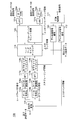
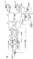
- FIG. 1 is a conceptual diagram of a MIMO system to which the present invention is applied. It is a figure which shows an example of the code book with which the base station apparatus which concerns on Embodiment 1 of this invention is provided. It is a figure which shows an example of the code book with which the base station apparatus which concerns on Embodiment 1 is provided. In the base station apparatus which concerns on Embodiment 1, it is a figure which shows an example of the zone
- 1 is a network configuration diagram of a mobile communication system to which a base station apparatus according to Embodiment 1 is applied.
- 3 is a partial block diagram showing a configuration of a base station apparatus according to Embodiment 1.
- FIG. 3 is a functional block diagram of a baseband signal processing unit of the base station apparatus according to Embodiment 1.
- FIG. 3 is a partial block diagram showing a configuration of a mobile station according to Embodiment 1.
- FIG. 3 is a functional block diagram of a baseband signal processing unit of a mobile station according to Embodiment 1.
- FIG. It is a figure which shows an example of the code book with which the base station apparatus which concerns on Embodiment 2 of this invention is provided. It is a figure which shows an example of the code book with which the base station apparatus which concerns on Embodiment 2 is provided.
- 6 is a functional block diagram of a baseband signal processing unit of a base station apparatus according to Embodiment 2.
- FIG. 6 is a functional block diagram of a baseband signal processing unit of a mobile station according to Embodiment 2.
- FIG. 1 is a conceptual diagram of a MIMO system to which a base station apparatus Node B according to the present invention is applied.
- FIG. 1 it has shown about the case where the user apparatus UE and the base station apparatus Node B are each provided with two antennas.
- the base station apparatus Node B determines the optimum number of layers for spatial multiplexing based on the uplink channel state (reception SINR, fading correlation between antennas). Rank information to be shown is selected, and the rank information is fed back to the user apparatus UE in the downlink.
- rank information indicating the content of information transmission in the spatial multiplexing transmission mode (here, for example, rank information indicating that the number of layers is “2”) )
- rank information indicating the content of information transmission in the transmission diversity transmission mode for the user equipment UE having a poor channel state (here, rank information indicating that the number of layers is “1”) Feedback.
- the number of layers is determined according to the rank information fed back from the base station apparatus Node B, and information is transmitted from each antenna.
- the base station apparatus Node B measures the channel fluctuation amount using the received signal from each antenna, and based on the measured channel fluctuation amount, A phase / amplitude control amount (precoding weight) that maximizes the throughput (or reception SINR) after combining the transmission data from each transmission antenna is selected. Then, the selected precoding weight is fed back to the user apparatus UE on the downlink. In user apparatus UE, information is transmitted from each antenna after precoding transmission data according to the precoding weight fed back from base station apparatus Node B.
- the base station apparatus Node B has a function for determining optimum rank information in rank adaptation and a function for determining optimum precoding weight in precoding based on channel conditions in the uplink. And a function of feeding back the precoding weight to the user apparatus UE.
- the base station apparatus Node B has a code book that defines N precoding weights known by both the base station apparatus Node B itself and the user apparatus UE, and the N precodings in the code book are provided. An optimum one is selected from the weights, and only the index can be fed back to the user apparatus UE.
- transmitting the phase / amplitude control amount is a concept including transmission of the precoding weight itself and transmission of only the index (number). The contents of the code book provided for the base station apparatus Node B will be described later.
- the user apparatus UE includes a layer mapping unit 10 that distributes uplink transmission data to the number of layers, two systems of multipliers 11a and 11b corresponding to two transmission antennas # 1 and # 2, and radio transmission circuits 12 and 13. It is comprised including.
- the precoding weights are added to the uplink transmission data by the multipliers 11a and 11b.
- the phase and amplitude are respectively controlled (shifted), and the phase and amplitude shifted transmission data is transmitted from the two transmission antennas # 1 and # 2.
- the rank information used in rank adaptation in such uplink MIMO transmission and the precoding weight used in precoding are appropriately fed back to the user apparatus UE, and the uplink The MIMO transmission is surely realized.
- an information feedback method used in uplink MIMO transmission in base station apparatus Node B according to the present embodiment will be described.
- Embodiment 1 In the information feedback method of base station apparatus Node B according to Embodiment 1, rank information used in rank adaptation in uplink MIMO transmission is fed back to user apparatus UE with a signal (for example, RRC signal) from an upper layer. A precoding weight used in precoding in uplink MIMO transmission is fed back to the user apparatus UE by a control channel signal.
- a signal for example, RRC signal
- the rank information is information for feeding back the optimum number of spatially multiplexed layers to the user apparatus UE, and the number of ranks according to the number of layers and information that can be transmitted to the user apparatus UE.
- the information that can convey the rank number to the user apparatus UE includes an uplink transmission mode (that is, a spatial multiplexing transmission mode or a transmission diversity transmission mode).
- an uplink transmission mode that is, a spatial multiplexing transmission mode or a transmission diversity transmission mode.
- rank information is fed back with a signal (RRC signal) from an upper layer, and therefore rank information is fed back to the user equipment UE with higher quality than when feedback is performed with a control channel signal. Therefore, it is possible to prevent erroneous recognition of rank information in the user apparatus UE, and it is possible to prevent deterioration of throughput characteristics due to erroneous recognition of rank information.
- the precoding weight is fed back to the user equipment UE by a control channel signal, the precoding weight in uplink MIMO transmission can be dynamically switched, so that it can flexibly cope with the uplink channel state. It is possible to realize the information transmission.
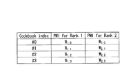
- FIG. 2 is a diagram illustrating an example of a code book provided in the base station apparatus Node B according to Embodiment 1.
- four precoding weights (PMI: PMI) are associated with rank 1 selected when the number of layers is “1” and rank 2 selected when the number of layers is “2”.
- Precoding Matrix Indicator is registered, and an index is associated with each precoding weight.
- the base station apparatus Node B reduces the amount of information required when feeding back the precoding weight by feeding back the rank information with the RRC signal and feeding back the index registered in the codebook in this way. It becomes possible to do. For example, when the user apparatus UE is instructed to set the number of layers to “2” and perform information transmission with the precoding weight W 2,0 , the rank 2 is fed back by the RRC signal and is shown in FIG. Index # 0 is fed back by the control channel signal. The user apparatus UE can recognize the precoding weight W 2,0 with reference to the code book by receiving feedback of the index # 0.
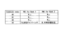
- FIG. 3 is a diagram illustrating an example of a code book that defines an uplink transmission mode corresponding to such open loop control.
- three precoding weights (PMI) are associated with rank 1 selected when the number of layers is “1” and rank 2 selected when the number of layers is “2”.
- uplink transmission modes corresponding to the open loop control are registered, and an index is associated with each precoding weight and uplink transmission mode.
- the index associated with this uplink transmission mode functions as a transmission mode index.
- the OL (Open Loop) transmission diversity transmission mode is registered.
- the OL spatial multiplexing transmission mode is registered.
- index # 3 is associated with each.
- the base station apparatus Node B by feeding back the index registered in such a codebook, the amount of information required for feeding back the precoding weight is reduced, and the channel state in the uplink is degraded. Therefore, it is possible to reduce the deterioration of the reception quality when the estimation accuracy of the channel fluctuation is deteriorated. For example, when rank 1 is fed back with an RRC signal, when index # 3 is fed back, information transmission in an open loop transmission diversity transmission mode may be fed back to user apparatus UE. It becomes possible.
- the base station apparatus Node B when determining the optimum rank information in rank adaptation, it is possible to select a band for measuring the channel state in the uplink.
- the channel state of the entire system band (here, 40 MHz) of the MIMO system to which the base station apparatus Node B is applied and FIG.
- the channel state for each component carrier here, 20 MHz
- the resource block of the band allocated to the user apparatus UE is divided into a plurality of cluster blocks in which some subbands are separated, the channel state of each cluster block may be selected as a measurement target It is possible to determine the optimum rank in each band.
- a “subband” composed of one or a plurality of subbands.
- the “band lump” is referred to as a cluster block.
- a “subband lump” composed of subbands # 2 and # 3 is defined as a first cluster block
- subband # 5 is defined as a second cluster block.
- an optimal rank is selected for each cluster block, and two rank information, ie, rank information for the first cluster block and rank information for the second cluster block, are transmitted via the downlink. Feedback to the device UE.
- the LTE scheme it is possible to obtain effects such as backward compatibility with the user terminal UE and improvement of throughput characteristics.
- the optimum rank is selected according to the channel state of the entire system band of the MIMO system, information transmission is performed with rank information common to the entire system band, and therefore rank information is fed back in the downlink. It is possible to reduce the amount of information for doing so.
- the user terminal of the LTE method that uses the maximum system band that can handle the component carrier Since the UE can also perform information transmission with optimal rank information, it is possible to ensure backward compatibility with the user terminal UE. Furthermore, when selecting the optimum rank information according to the channel state for each cluster block allocated to the user apparatus UE, the number of layers of transmission data in the user apparatus UE is switched for each cluster block, so that the base station It is possible to reduce reception errors in the device Node B and improve the throughput characteristics.
- the rank number is fed back as rank information to the user apparatus UE from the base station apparatus Node B by the RRC signal.
- the user apparatus UE can directly recognize the number of layers of transmission data and can efficiently perform a process of switching the number of layers of transmission data. It becomes.
- the rank information fed back to the user apparatus UE in order to realize rank adaptation in uplink MIMO transmission may be the uplink transmission mode as described above. As described above, even when the uplink transmission mode is fed back as the rank information using the RRC signal, the same effect as when the rank number is fed back can be obtained.
- the uplink transmission mode when the uplink transmission mode is fed back as rank information, the type of information to be fed back can be reduced compared to the number of ranks, so that the amount of information for feeding back rank information can be reduced. Become. It is also possible to feed back the combination of the uplink transmission mode and the number of ranks as rank information.
- FIG. 5 is a network configuration diagram of a mobile communication system to which the base station apparatus Node B according to Embodiment 1 is applied.
- the mobile communication system 1000 is a system to which, for example, LTE (Long Term Evolution) -Advanced is applied.
- the mobile communication system 1000 includes a base station device 200 and a plurality of mobile stations 100 (100 1 , 100 2 , 100 3 ,... 100 n , where n is an integer of n> 0) communicating with the base station device 200.
- Base station apparatus 200 is connected to an upper station, for example, access gateway apparatus 300, and access gateway apparatus 300 is connected to core network 400.
- the mobile station 100n communicates with the base station apparatus 200 in the cell 50 using Evolved UTRA and UTRAN.
- the access gateway device 300 may be called MME / SGW (Mobility Management Entity / Serving Gateway).
- each mobile station (100 1 , 100 2 , 100 3 ,... 100 n ) has the same configuration, function, and state, the following description will be given as the mobile station 100 unless otherwise noted. Shall proceed.
- the mobile station 100 wirelessly communicates with the base station apparatus 200, but more generally user equipment (UE: User Equipment) including both mobile terminals and fixed terminals may be used.
- UE User Equipment
- radio access based on OFDMA (Orthogonal Frequency Division Multiple Access) for the downlink and SC-FDMA (Single Carrier-Frequency Division Multiple Access) is applied for the uplink as the radio access scheme.
- OFDMA Orthogonal Frequency Division Multiplexing Access
- SC-FDMA Single-Carrier Frequency Division Multiple Access
- a physical downlink shared channel (PDSCH) shared by each mobile station 100 and a physical downlink control channel (PDCCH: Physical Downlink Control Channel, which is a downlink control channel), downlink L1 / L2 control channel).
- PDSCH physical downlink shared channel
- PDCCH Physical Downlink Control Channel, which is a downlink control channel
- User data that is, a normal data signal is transmitted through the physical downlink shared channel.
- precoding information for uplink MIMO transmission by the physical downlink control channel ID of a user who performs communication using the physical downlink shared channel, and information on the transport format of the user data, that is, downlink Scheduling Information, the ID of a user who performs communication using the physical uplink shared channel, and information on the transport format of the user data, that is, Uplink Scheduling Grant, etc. are fed back.
- broadcast channels such as Physical-Broadcast Channel (P-BCH) and Dynamic Broadcast Channel (D-BCH) are transmitted.
- Information transmitted by the P-BCH is a Master Information Block (MIB)
- information transmitted by the D-BCH is a System Information Block (SIB).
- SIB System Information Block
- the D-BCH is mapped to the PDSCH and transmitted from the base station apparatus 200 to the mobile station 100n.
- an RRC signal for feeding back rank information is mapped to PDSCH and transmitted to mobile station 100n.
- User data that is, a normal data signal is transmitted through the physical uplink shared channel.
- precoding information for downlink MIMO transmission, acknowledgment information for downlink shared channels, downlink radio quality information (CQI: Channel Quality Indicator), and the like are transmitted by the physical uplink control channel.
- CQI Channel Quality Indicator
- a physical random access channel for initial connection and the like is defined.
- the mobile station 100 transmits a random access preamble to the base station apparatus 200 in the PRACH.
- base station apparatus 200 includes two transmission / reception antennas 202a and 202b for MIMO transmission, amplifier sections 204a and 204b, transmission / reception sections 206a and 206b, and a baseband signal.
- a processing unit 208, a call processing unit 210, and a transmission path interface 212 are provided.
- the transmission / reception units 206a and 206b function as transmission units in the present invention.
- User data transmitted from the base station apparatus 200 to the mobile station 100 via the downlink is a baseband signal processing unit from an upper station located above the base station apparatus 200, for example, the access gateway apparatus 300 via the transmission path interface 212. 208 is input.
- the baseband signal processing unit 208 performs PDCP layer processing, user data division / combination, RLC layer transmission processing such as RLC (Radio Link Control) retransmission control transmission processing, MAC (Medium Access Control) retransmission control, for example, HARQ (Hybrid Automatic Repeat reQuest) transmission processing, scheduling, transmission format selection, channel coding, inverse fast Fourier transform (IFFT) processing, and precoding processing are performed and transferred to the transmission / reception units 206a and 206b. Is done.
- the physical downlink control channel signal is also subjected to transmission processing such as channel coding and inverse fast Fourier transform, and transferred to the transmission / reception units 206a and 206b.
- the baseband signal processing unit 208 feeds back control information for communication in the cell to the mobile station 100 through the broadcast channel described above.
- the control information for communication in the cell includes, for example, system bandwidth in uplink or downlink, resource block information allocated to the mobile station 100, and identification of a route sequence for generating a random access preamble signal in PRACH Information (Root Sequence Index) etc. are included.
- frequency conversion processing for converting the baseband signal output by precoding from the baseband signal processing unit 208 to each antenna is converted to a radio frequency band, and then amplified by the amplifier units 204a and 204b. And transmitted from the transmitting and receiving antennas 202a and 202b.
- the radio frequency signals received by the transmission / reception antennas 202a and 202b are amplified by the amplifier units 204a and 204b, and the frequency is transmitted by the transmission / reception units 206a and 206b. It is converted into a baseband signal and input to the baseband signal processing unit 208.
- the baseband signal processing unit 208 performs FFT processing, IDFT processing, error correction decoding, MAC retransmission control reception processing, RLC layer, and PDCP layer reception processing on user data included in the input baseband signal. And transferred to the access gateway apparatus 300 via the transmission path interface 212.
- the call processing unit 210 performs call processing such as communication channel setting and release, state management of the radio base station 200, and radio resource management.
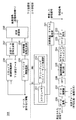
- FIG. 7 is a functional block diagram of baseband signal processing section 208 of base station apparatus 200 according to Embodiment 1.
- the reference signal included in the received signal is input to the synchronization detection / channel estimation unit 221.
- the synchronization detection / channel estimation unit 221 estimates the uplink channel state based on the reception state of the reference signal received from the mobile station 100.
- the received signal input to the baseband signal processing unit 208 is subjected to Fourier transform by the fast Fourier transform unit 223 after the cyclic prefix added to the received signal is removed by the CP (Cyclic Prefix) removal unit 222. Converted to frequency domain information.
- the received signal converted into frequency domain information is demapped in the frequency domain by subcarrier demapping section 224.
- the subcarrier demapping unit 224 performs demapping corresponding to the mapping at the mobile station 100.
- the frequency domain equalization unit 225 equalizes the received signal based on the channel estimation value given from the synchronization detection / channel estimation unit 221.
- the inverse discrete Fourier transform unit 226 performs an inverse discrete Fourier transform on the received signal to return the frequency domain signal to the time domain signal.
- the data demodulator 227 and the data decoder 228 reproduce the transmission data based on the transmission format (coding rate, demodulation method).
- the scheduler 231 determines the uplink / downlink resource allocation content based on the channel estimation value given from the synchronization detection / channel estimation unit 221.
- the reference signal used for quality measurement that is the basis of scheduling needs to occupy a band over all resource blocks (system band).
- the mobile station 100 transmits the quality measurement reference signal in a wider band than the resource block to which the resource is actually allocated.
- the scheduler 231 can acquire channel state information from a CQI measurement unit (not shown).
- the CQI measurement unit measures a channel state from a broadband quality measurement reference signal received from the mobile station 100.
- the precoding weight / rank number selection unit 232 determines the antenna in the mobile station 100 from the uplink reception quality in the resource block allocated to the mobile station 100.
- a precoding weight for controlling the phase and / or amplitude of the transmission signal is determined every time. That is, the precoding weight / rank number selection unit 232 functions as a control amount determination unit in the present invention.
- the precoding weight / rank number selection unit 232 controls the phase and / or amplitude of the transmission signal for each antenna in the mobile station 100 from the uplink reception quality in the resource block allocated to the mobile station 100.
- the coding weight can be determined.
- the precoding weight / rank number selection unit 232 determines the rank number indicating the number of spatially multiplexed layers in the uplink, based on the channel estimation value given from the synchronization detection / channel estimation unit 221. That is, the precoding weight / rank number selection unit 232 functions as a rank information determination unit in the present invention.
- the precoding weight / rank number selection unit 232 has a precoding weight (PMI) and a rank number (RI: Rank Indicator) that maximize the throughput (or reception SINR). Select.
- PMI precoding weight
- RI rank Indicator
- Select when determining the precoding weight, the above-described codebook in which the indexes of the plurality of types of precoding weights are defined can be selected from the codebook (see FIGS. 2 and 3). ). Further, when determining the number of ranks, it is possible to select a band to be measured in the uplink (see FIG. 4).
- the precoding weight / rank number selection unit 232 selects the channel state of the entire system band (in this case, 40 MHz) as a measurement target, and according to the channel state.
- the optimal number of ranks can be selected.
- the channel state for each component carrier obtained by dividing the system band into a plurality of blocks can be selected as a measurement target, and the optimal number of ranks can be selected according to the channel state. .
- the feedback information selection unit 233 selects how much precoding information is finally fed back from the precoding weights selected by the precoding weight / rank number selection unit 232. Then, the selected precoding information is input to the control information signal generation unit 234 as feedback information.
- This feedback information and resource allocation information for the mobile station 100 are input to the control information signal generation unit 234.
- the control information signal generation unit 234 generates L1 / L2 control information to be multiplexed on the physical downlink control channel based on the feedback information and the resource allocation information, and inputs the L1 / L2 control information to the OFDM modulation unit 235.
- the upper layer control information selection unit 236 selects which rank number is to be fed back based on the rank number selected by the precoding weight / rank number selection unit 232. Specifically, one of the number of ranks for the entire system band, the number of ranks for each component carrier, and the number of ranks for each cluster block is selected. Then, the selected rank number is input to the transmission data signal generation unit 237 as feedback information.
- the transmission data signal generation unit 237 receives this feedback information and downlink transmission data for the mobile station 100. Based on the feedback information and the downlink transmission data, the transmission data signal generation unit 237 generates downlink transmission data that is actually transmitted through the physical downlink shared channel (PDSCH), and is input to the OFDM modulation unit 235.
- the downlink transmission data generated by the transmission data signal generation unit 237 includes an RRC signal that feeds back the number of ranks selected by the higher layer control information selection unit 236.
- the OFDM modulation unit 235 performs OFDM modulation processing on the two series of signals including the L1 / L2 control information input from the control information signal generation unit 234 and the downlink transmission data input from the transmission data signal generation unit 237. And sent to the transmitting / receiving units 206a and 206b.
- base station apparatus 200 selects the rank number and precoding weight that maximize the throughput (or received SINR) based on the channel estimation value given from synchronization detection / channel estimation section 221, and sets the rank number. While included in the RRC signal, the precoding weight is included in the L1 / L2 control information multiplexed on the PDCCH and can be transmitted to the user apparatus UE.
- mobile station 100 includes two transmission / reception antennas 102a and 102b for MIMO transmission, amplifier sections 104a and 104b, transmission / reception sections 106a and 106b, and baseband signal processing.
- Unit 108 and application unit 110 are two transmission / reception antennas 102a and 102b for MIMO transmission, amplifier sections 104a and 104b, transmission / reception sections 106a and 106b, and baseband signal processing.
- Unit 108 and application unit 110 Unit
- radio frequency signals received by the two transmission / reception antennas 102a and 102b are amplified by the amplifier units 104a and 104b, frequency-converted by the transmission / reception units 106a and 106b, and converted into baseband signals.
- the baseband signal is subjected to FFT processing, error correction decoding, retransmission control reception processing, and the like by the baseband signal processing unit 108.
- downlink user data is transferred to the application unit 110.
- the application unit 110 performs processing related to layers higher than the physical layer and the MAC layer. Also, broadcast information in the downlink data is also transferred to the application unit 110.
- uplink user data is input from the application unit 110 to the baseband signal processing unit 108.
- the baseband signal processing unit 108 performs retransmission control (H-ARQ: Hybrid ARQ) transmission processing, channel coding, precoding, DFT processing, IFFT processing, and the like, and transfers them to the transmission / reception units 106a and 106b.
- H-ARQ Hybrid ARQ
- frequency conversion processing for converting the baseband signal output from the baseband signal processing unit 108 into a radio frequency band is performed, and then amplified by the amplifier units 104a and 104b and transmitted / received antennas 102a and 102b. Will be sent.
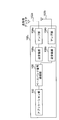
- FIG. 9 is a functional block diagram of the baseband signal processing unit 108 of the mobile station 100 according to Embodiment 1.
- Reception signals output from the transmission / reception units 106 a and 106 b are demodulated by the OFDM demodulation unit 111.
- the data signal is input to the downlink data signal decoder 112, and the control signal (PDCCH) is input to the downlink control signal decoder 113.
- the downlink data signal decoding unit 112 decodes downlink transmission data and reproduces downlink transmission data.
- the reproduced transmission data includes an RRC signal that feeds back the number of uplink ranks.
- the downlink control signal decoding unit 113 decodes a downlink control signal (PDCCH), and reproduces uplink precoding information, scheduling information (resource allocation information), and the like.
- PDCCH downlink control signal
- the number of uplink ranks is input to the serial-parallel conversion unit 114 and a codeword layer mapping unit 119 described later.
- the serial / parallel converter 114 receives the number of uplink ranks and the uplink transmission data.
- the serial / parallel conversion unit 114 performs serial / parallel conversion of the transmission data into the number of codewords according to the input uplink rank number.
- the code word indicates a coding unit of channel coding, and the number (code word number) is uniquely determined by the number of ranks and / or the number of transmission antennas.
- the number of code words is determined to be two is shown.
- the transmission data (code word signal # 1, code word signal # 2) subjected to serial / parallel conversion by the serial / parallel conversion unit 114 is input to the data encoding units 115a and 115b.
- the code word signal # 1 from the serial / parallel conversion unit 114 is encoded.
- the codeword signal # 1 encoded by the data encoding unit 115a is modulated by the data modulation unit 116a, and inverse Fourier transformed by the discrete Fourier transform unit 117a to convert time-series information into frequency domain information.
- the subcarrier mapping unit 118a performs mapping in the frequency domain based on the scheduling information from the downlink control signal decoding unit 113. Then, the mapped codeword signal # 1 is input to the codeword layer mapping unit 119.
- the same processing is performed on the codeword signal # 2, and the mapped codeword signal # 2 is converted into the codeword layer. Input to the mapping unit 119.
- codeword signals # 1 and # 2 input from subcarrier mapping sections 118a and 118b are distributed to the number of layers according to the number of uplink ranks from downlink data signal decoding section 112. Is done.
- the distributed code word signals # 1 and # 2 are input to the precoding weight multiplication unit 120.
- the precoding weight multiplication unit 120 shifts the phase and / or amplitude of the transmission signal for each of the transmission and reception antennas 102a and 102b (weighting of the transmission antenna by precoding). ). Thereby, the reception power of the received signal in base station apparatus 200 can be increased, and the throughput characteristics can be improved.
- the inverse fast Fourier transform units 121a and 121b transform the transmission signal into an inverse fast Fourier transform to convert the frequency domain signal into a time domain signal.
- cyclic prefix adding units 122a and 122b add a cyclic prefix to the transmission signal.
- the cyclic prefix functions as a guard interval for absorbing a multipath propagation delay and a difference in reception timing among a plurality of users in the base station.
- the transmission signal to which the cyclic prefix is added is sent to the transmission / reception units 106a and 106b.
- the downlink data signal and downlink control information transmitted from the base station apparatus 200 are decoded, and the rank number and precoding weight fed back from the base station apparatus 200 are obtained. Then, the number of layers of transmission data is determined based on the number of ranks and the precoding weight, and after performing precoding with the precoding weight, the transmission data is transmitted from the antennas 102a and 102b. That is, in the mobile station 100, transmission data can be transmitted to the base station apparatus 200 according to the number of ranks and the precoding weight fed back from the base station apparatus 200.
- the rank information determined by precoding weight / rank number selection section 232 is transmitted to mobile station 100 using the RRC signal, and the precoding weight is controlled. Since transmission is performed using a channel signal, feedback information (rank information and precoding information) for rank adaptation and precoding in uplink MIMO transmission can be appropriately fed back to the mobile station 100. Then, the mobile station 100 determines the number of layers of transmission data according to the rank information fed back in this way, and shifts the phase and / or amplitude of the transmission signal for each of the transmission / reception antennas 102a and 102b according to the precoding information. Thus, uplink MIMO transmission can be appropriately realized.
- Embodiment 2 In the information feedback method of the base station apparatus Node B according to Embodiment 1, the rank information used in rank adaptation in uplink MIMO transmission is fed back to the user apparatus UE with a signal (RRC signal) from an upper layer, and the uplink A precoding weight used in precoding in the MIMO transmission of the link is fed back to the user apparatus UE by a control channel signal.
- RRC signal a signal
- both rank information used in rank adaptation in uplink MIMO transmission and precoding weight used in precoding in uplink MIMO transmission are controlled. It differs from the information feedback method of base station apparatus Node B according to Embodiment 1 in that it is fed back to user apparatus UE with a channel signal.
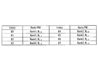
- FIG. 10 is a diagram illustrating an example of a code book provided in the base station apparatus Node B according to Embodiment 2.
- a combination of 2 and 4 precoding weights (PMI) is registered, and an index is associated with each combination.
- the base station apparatus Node B it is possible to reduce the amount of information necessary for feedback of the rank information and the precoding weight by feeding back the index registered in the codebook in this way. For example, when the user apparatus UE is instructed to set the number of layers to “2” and perform information transmission with the precoding weight W 2 , 0 , the index # 4 is fed back with the control channel signal. In the user apparatus UE, it is possible to recognize rank 2 and precoding weights W 2,0 by referring to the code book by receiving feedback of the index # 4.
- the channel state in the uplink is measured.
- the band to be selected can be selected. That is, also in the base station apparatus Node B according to the second embodiment, the channel state of the entire system band, the channel state for each component carrier, and the channel state for each cluster block can be selected as measurement targets. It is possible to select the optimum rank information in the band.
- the base station apparatus Node B includes both the code book shown in FIG. 10 and the code book shown in FIG. 2, and an index that indicates a combination of rank information and precoding weight, an index that indicates precoding weight, May be used to feed back the rank information and precoding weight to the user apparatus UE.
- the rank information and the precoding weight are fed back in this way, as shown in FIG. 4C, the rank information is fed back for each cluster block, and the rank information to be fed back is common. The amount of information for feeding back rank information can be reduced.
- the precoding weights of the first and second cluster blocks are respectively precoding weights.
- W 2,0 and W 2,3 first, the index # 0 shown in FIG. 10 is fed back, and then the index # 3 shown in FIG. It is possible to reduce the amount of information for feedback.
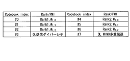
- FIG. 11 is a diagram illustrating an example of a code book that defines an uplink transmission mode corresponding to such open loop control.
- a combination of 2 and 3 precoding weights (PMI) and two uplink transmission modes corresponding to open loop control are registered, and an index is associated with each combination and uplink transmission mode.
- PMI precoding weights
- an OL (Open Loop) transmission diversity transmission mode and an OL spatial multiplexing transmission mode are registered, and indexes # 3 and # 7 are associated with each other.
- the base station apparatus Node B by feeding back the index registered in such a codebook, while reducing the amount of information required for feeding back rank information and precoding weight, the channel state in the uplink It is possible to reduce the degradation of the reception quality when the estimation accuracy of channel fluctuations deteriorates due to degradation of. For example, when rank 1 and precoding weights W 1 and 0 are fed back using a control channel signal, if index # 3 is fed back, the user may perform information transmission in an open loop transmission diversity transmission mode. It is possible to instruct the device UE.
- control channel signal for example, PHICH (Physical Hybrid-ARQ Indicator Channel) may be used.
- rank information and precoding weight are used together with control information such as scheduling information.
- rank information and precoding weight can be fed back using an existing control channel signal, whereas when the latter is used as a control channel signal, rank information and Rank information and precoding weight can be fed back with higher quality than when the recoding weight is fed back, thereby preventing the rank information from being misrecognized in the user apparatus UE, and the rank information being misrecognized. It is possible to prevent the degradation of the throughput characteristics due to the above.
- Base station apparatus 600 and mobile station 500 according to Embodiment 2 are the same as base station apparatus 200 (see FIG. 6) and mobile station 100 (see FIG. 6) according to Embodiment 1, except for the configuration of the baseband signal processing unit included in them. 8). Also, the mobile communication system to which these base station apparatus 600 and mobile station 500 are applied is also common to mobile communication system 1000 according to Embodiment 1.
- FIG. 12 is a functional block diagram of baseband signal processing section 608 of base station apparatus 600 according to Embodiment 2.
- FIG. 13 is a functional block diagram of baseband signal processing section 508 of mobile station 500 according to Embodiment 2.
- the configurations of the baseband signal processing unit 608 and the baseband signal processing unit 508 shown in FIGS. 12 and 13 are the same as the baseband signal processing unit 208 shown in FIG. 7 and the baseband signal processing unit 108 shown in FIG. Constituent symbols are assigned to the configurations, and descriptions thereof are omitted.
- feedback 7 is different from the baseband signal processing unit 208 shown in FIG. 7 in that the information selection unit 612 and the control information signal generation unit 613 are provided, and the upper layer control information selection unit 236 is not provided.
- the precoding weight / rank number selection unit 611 is different from the precoding weight / rank number selection unit 232 in that the determined precoding weight and rank number are input to the feedback information selection unit 612.
- the feedback information selection unit 612 is different from the feedback information selection unit 233 in that it has the function of the upper layer control information selection unit 236. That is, the feedback information selection unit 612 selects how much precoding information is finally fed back from the precoding weights selected by the precoding weight / rank number selection unit 611, and the precoding weight / Based on the number of ranks selected by the rank number selection unit 611, which rank number is to be fed back is selected. Then, the selected precoding weight and rank number are input to the control information signal generation unit 613 as feedback information.
- the control information signal generation unit 613 generates L1 / L2 control information to be multiplexed on the physical downlink control channel (PDCCH) based on the feedback information (precoding weight and number of ranks) and resource allocation information for the mobile station 100. This is different from the control information signal generator 234 in that respect.
- PDCCH physical downlink control channel
- the base station apparatus 600 Since the baseband processing unit 608 has such a configuration, the base station apparatus 600 has a rank that maximizes the throughput (or reception SINR) based on the channel estimation value given from the synchronization detection / channel estimation unit 221. The number and the precoding weight are selected, and both the rank number and the precoding weight can be included in the L1 / L2 control information multiplexed on the PDCCH and transmitted to the user apparatus UE.
- the baseband signal processing unit 508 illustrated in FIG. 13 includes a downlink data signal decoding unit 511 and a downlink control signal decoding unit 512 instead of the downlink data signal decoding unit 112 and the downlink control signal decoding unit 113. This is different from the baseband signal processing unit 108 shown in FIG.
- the downlink data signal decoding unit 511 is different from the downlink data signal decoding unit 112 in that it has only a function of decoding downlink transmission data and reproducing downlink transmission data. That is, the transmission data reproduced by the downlink data signal decoding unit 511 does not include an RRC signal that feeds back the number of uplink ranks. For this reason, the downlink data signal decoding unit 511 does not input the uplink rank number to the serial-parallel conversion unit 114.
- the downlink control signal decoding unit 512 decodes the downlink control signal (PDCCH) and reproduces the uplink rank as well as the uplink precoding information and scheduling information (resource allocation information). This is different from the downlink control signal decoding unit 113.
- the downlink control signal decoding unit 512 is different from the downlink control signal decoding unit 113 in that the number of uplink ranks is input to the serial / parallel conversion unit 114 and the codeword layer mapping unit 119.
- the mobile station 500 decodes the downlink control information transmitted from the base station apparatus 600, and the number of ranks and the precoding weight fed back from the base station apparatus 600. Get. Then, the number of layers of transmission data is determined based on the number of ranks and the precoding weight, and after performing precoding with the precoding weight, the transmission data is transmitted from the antennas 102a and 102b. That is, mobile station 500 can transmit transmission data to base station apparatus 600 according to the number of ranks fed back from base station apparatus 600 and the precoding weight.
- both rank information and precoding weight determined by precoding weight / rank number selection section 411 are transmitted to mobile station 500 using a control channel signal. Therefore, in uplink MIMO transmission, feedback information (rank information and precoding information) for rank adaptation and precoding can be appropriately fed back to the mobile station 500. Then, the mobile station 500 determines the number of layers of transmission data according to the rank information fed back in this way, and shifts the phase and / or amplitude of the transmission signal for each of the transmission / reception antennas 102a and 102b according to the precoding information. Thus, uplink MIMO transmission can be appropriately realized.
- uplink SC-FDMA is assumed, but any scheme of OFDM, Clustered DFT-s-OFDM, or hybrid access can be applied.
Landscapes
- Engineering & Computer Science (AREA)
- Signal Processing (AREA)
- Computer Networks & Wireless Communication (AREA)
- Physics & Mathematics (AREA)
- Mathematical Physics (AREA)
- Quality & Reliability (AREA)
- Power Engineering (AREA)
- Mobile Radio Communication Systems (AREA)
- Radio Transmission System (AREA)
Abstract
Description
まず、本発明に係る基地局装置が適用されるMIMOシステムで行われる上りリンクMIMO伝送におけるランクアダプテーション及びプリコーディングについて、図1に示すMIMOシステムを前提に説明する。図1は、本発明に係る基地局装置Node Bが適用されるMIMOシステムの概念図である。なお、図1に示すMIMOシステムにおいては、ユーザ装置UE及び基地局装置Node Bがそれぞれ2本のアンテナを備える場合について示している。
実施の形態1に係る基地局装置Node Bの情報フィードバック方法においては、上りリンクMIMO伝送におけるランクアダプテーションで用いられるランク情報を上位レイヤからの信号(例えば、RRC信号)でユーザ装置UEにフィードバックすると共に、上りリンクのMIMO伝送におけるプリコーディングで用いられるプリコーディングウェイトを制御チャネル信号でユーザ装置UEにフィードバックするものである。
実施の形態1に係る基地局装置Node Bの情報フィードバック方法においては、上りリンクMIMO伝送におけるランクアダプテーションで用いられるランク情報を上位レイヤからの信号(RRC信号)でユーザ装置UEにフィードバックすると共に、上りリンクのMIMO伝送におけるプリコーディングで用いられるプリコーディングウェイトを制御チャネル信号でユーザ装置UEにフィードバックする。実施の形態2に係る基地局装置Node Bの情報フィードバック方法においては、上りリンクMIMO伝送におけるランクアダプテーションで用いられるランク情報、並びに、上りリンクのMIMO伝送におけるプリコーディングで用いられるプリコーディングウェイトを共に制御チャネル信号でユーザ装置UEにフィードバックする点で実施の形態1に係る基地局装置Node Bの情報フィードバック方法と相違する。
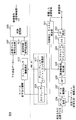
Claims (16)
- 上りリンクにおける空間多重のレイヤ数に対応するランク情報を決定するランク情報決定部と、
ユーザ装置の送信アンテナに対する重み付けに用いる送信位相及び又は送信振幅の制御量を決定する制御量決定部と、
前記ランク情報決定部で決定した前記ランク情報を上位レイヤからの信号で前記ユーザ装置に送信すると共に、前記制御量決定部で決定した前記制御量を制御チャネル信号で前記ユーザ装置に送信する送信部と、
を具備することを特徴とする基地局装置。 - 予めユーザ装置の送信アンテナに対する重み付けに用いられる送信位相及び又は送信振幅の制御量を示す複数種類のインデックスが、上りリンクにおける空間多重のレイヤ数に対応するランク情報毎に定められたコードブックを備え、前記送信部は、前記インデックスを前記制御量として前記ユーザ装置に送信することを特徴とする請求項1記載の基地局装置。
- 前記コードブックに、開ループ型の上りリンク伝送モードを指定する伝送モードインデックスを定めておき、前記情報フィードバック部は、前記伝送モードインデックスを前記ユーザ装置に送信することを特徴とする請求項2記載の基地局装置。
- 上りリンクにおける空間多重のレイヤ数に対応するランク情報を決定するランク情報決定部と、
ユーザ装置の送信アンテナに対する重み付けに用いる送信位相及び又は送信振幅の制御量を決定する制御量決定部と、
前記ランク情報決定部で決定した前記ランク情報及び前記制御量決定部で決定した前記制御量を制御チャネル信号で前記ユーザ装置に送信する送信部と、
を具備することを特徴とする基地局装置。 - 前記送信部は、PDCCHにより前記ランク情報及び制御量を前記ユーザ装置に送信することを特徴とする請求項4記載の基地局装置。
- 前記送信部は、PDCCHと異なるフィードバック用の制御チャネル信号により前記ランク情報及び制御量を前記ユーザ装置に送信することを特徴とする請求項4記載の基地局装置。
- 予めユーザ装置の送信アンテナに対する重み付けに用いられる送信位相及び又は送信振幅の制御量と、上りリンクにおける空間多重のレイヤ数を示すランク情報との組み合わせを示す複数種類のインデックスが定められたコードブックを備え、前記情報フィードバック部は、前記インデックスを前記ランク情報及び制御量として前記ユーザ装置に送信することを特徴とする請求項4記載の基地局装置。
- 前記コードブックに、開ループ型の上りリンク伝送モードを指定する伝送モードインデックスを含め、前記情報フィードバック部は、前記伝送モードインデックスを前記ユーザ装置に送信することを特徴とする請求項7記載の基地局装置。
- 前記ランク情報決定部は、前記ランク情報として、上りリンクにおける空間多重のレイヤ数に対応するランク数を決定することを特徴とする請求項1記載の基地局装置。
- 前記ランク情報決定部は、前記ランク情報として、上りリンクにおける空間多重のレイヤ数に対応する上りリンク伝送モードを決定することを特徴とする請求項1記載の基地局装置。
- 前記ランク情報決定部は、システム帯域全体で共通する最適なレイヤ数に応じた前記ランク情報を決定することを特徴とする請求項1記載の基地局装置。
- 前記ランク情報決定部は、システム帯域を複数のブロックに分割したコンポーネントキャリア毎に最適なレイヤ数に応じた前記ランク情報を決定することを特徴とする請求項1記載の基地局装置。
- 前記ランク情報決定部は、前記ユーザ装置に割り当てた帯域のリソースブロックが、一部のサブバンドが離れた状態となる複数のクラスターブロックに分割されている場合に当該クラスターブロック毎に最適なレイヤ数に応じた前記ランク情報を決定することを特徴とする請求項1記載の基地局装置。
- 予めユーザ装置の送信アンテナに対する重み付けに用いられる送信位相及び又は送信振幅の制御量と、上りリンクにおける空間多重のレイヤ数を示すランク情報との組み合わせを示す複数種類の第1のインデックスが定められた第1のコードブックと、予めユーザ装置の送信アンテナに対する重み付けに用いられる送信位相及び又は送信振幅の制御量を示す複数種類の第2のインデックスが、上りリンクにおける空間多重のランク情報毎に定められた第2のコードブックとを備え、前記送信部は、前記第1のインデックスを前記ユーザ装置の一の送信アンテナに対する前記ランク情報及び制御量として送信すると共に、前記第2のインデックスを前記ユーザ装置の他の送信アンテナに対する前記制御量として送信することを特徴とする請求項13記載の基地局装置。
- 上りリンクにおける空間多重のレイヤ数に対応するランク情報を決定するステップと、
ユーザ装置の送信アンテナに対する重み付けに用いる送信位相及び又は送信振幅の制御量を決定するステップと、
前記決定したランク情報を上位レイヤからの信号で前記ユーザ装置に送信すると共に、前記決定した制御量を制御チャネル信号で前記ユーザ装置に送信するステップと、
を具備することを特徴とする情報フィードバック方法。 - 上りリンクにおける空間多重のレイヤ数に対応するランク情報を決定するステップと、
ユーザ装置の送信アンテナに対する重み付けに用いる送信位相及び又は送信振幅の制御量を決定するステップと、
前記決定したランク情報及び前記決定した制御量を制御チャネル信号で前記ユーザ装置に送信するステップと、
を具備することを特徴とする情報フィードバック方法。
Priority Applications (5)
| Application Number | Priority Date | Filing Date | Title |
|---|---|---|---|
| KR1020117029179A KR101373096B1 (ko) | 2009-06-23 | 2010-06-23 | 기지국장치 및 정보 피드백 방법 |
| CA2763430A CA2763430A1 (en) | 2009-06-23 | 2010-06-23 | Base station apparatus and information feedback method |
| EP10792116.5A EP2448160A4 (en) | 2009-06-23 | 2010-06-23 | BASE STATION DEVICE AND INFORMATION RETURN METHOD |
| US13/378,678 US8780839B2 (en) | 2009-06-23 | 2010-06-23 | Base station apparatus and information feedback method |
| CN2010800280500A CN102461038A (zh) | 2009-06-23 | 2010-06-23 | 基站装置以及信息反馈方法 |
Applications Claiming Priority (2)
| Application Number | Priority Date | Filing Date | Title |
|---|---|---|---|
| JP2009148997A JP5325672B2 (ja) | 2009-06-23 | 2009-06-23 | 基地局装置及び情報フィードバック方法 |
| JP2009-148997 | 2009-06-23 |
Publications (1)
| Publication Number | Publication Date |
|---|---|
| WO2010150798A1 true WO2010150798A1 (ja) | 2010-12-29 |
Family
ID=43386567
Family Applications (1)
| Application Number | Title | Priority Date | Filing Date |
|---|---|---|---|
| PCT/JP2010/060610 WO2010150798A1 (ja) | 2009-06-23 | 2010-06-23 | 基地局装置及び情報フィードバック方法 |
Country Status (7)
| Country | Link |
|---|---|
| US (1) | US8780839B2 (ja) |
| EP (1) | EP2448160A4 (ja) |
| JP (1) | JP5325672B2 (ja) |
| KR (1) | KR101373096B1 (ja) |
| CN (1) | CN102461038A (ja) |
| CA (1) | CA2763430A1 (ja) |
| WO (1) | WO2010150798A1 (ja) |
Cited By (1)
| Publication number | Priority date | Publication date | Assignee | Title |
|---|---|---|---|---|
| US20220311484A1 (en) * | 2011-04-19 | 2022-09-29 | Sun Patent Trust | Pre-coding method and pre-coding device |
Families Citing this family (23)
| Publication number | Priority date | Publication date | Assignee | Title |
|---|---|---|---|---|
| KR20100019948A (ko) * | 2008-08-11 | 2010-02-19 | 엘지전자 주식회사 | 공간 다중화 기법을 이용한 데이터 전송방법 |
| KR101624148B1 (ko) * | 2009-12-30 | 2016-06-07 | 삼성전자주식회사 | 네트워크 다중 입출력 무선통신 시스템에서 채널 상태 정보 송수신 방법 및 장치 |
| CN101834708B (zh) | 2010-04-30 | 2015-01-28 | 中兴通讯股份有限公司 | 一种信道信息的获取方法及装置 |
| JP5484304B2 (ja) * | 2010-12-10 | 2014-05-07 | 三菱電機株式会社 | 無線基地局装置及び通信条件決定方法 |
| WO2012128446A1 (ko) * | 2011-03-21 | 2012-09-27 | 엘지전자 주식회사 | 다중 노드 시스템에서 신호 전송 방법 및 장치 |
| JP6026082B2 (ja) * | 2011-04-05 | 2016-11-16 | シャープ株式会社 | 端末、基地局、通信方法および集積回路 |
| US20140023033A1 (en) * | 2011-04-13 | 2014-01-23 | Lg Electronics Inc. | Method and apparatus for transceiving channel status information and transceiver |
| CN102882657B (zh) | 2011-07-15 | 2018-01-23 | 瑞典爱立信有限公司 | 用于上行链路秩自适应的方法、设备和系统 |
| CN104322100B (zh) * | 2012-06-11 | 2018-05-18 | 华为技术有限公司 | 上行数据传输方法及装置 |
| CN104205705B (zh) * | 2012-06-11 | 2018-03-09 | 华为技术有限公司 | 上行数据传输方法及装置 |
| KR101348394B1 (ko) * | 2012-06-29 | 2014-01-16 | 인텔렉추얼디스커버리 주식회사 | 다중 안테나 통신 시스템에서의 송수신 장치 및 피드백 신호 전송 방법 |
| US9014069B2 (en) * | 2012-11-07 | 2015-04-21 | Qualcomm Incorporated | Methods and apparatus for communication mode selection based on content type |
| WO2014084638A1 (en) * | 2012-11-28 | 2014-06-05 | Samsung Electronics Co., Ltd. | Method and apparatus for performing communication in a wireless communication system |
| KR102117024B1 (ko) * | 2012-11-28 | 2020-06-01 | 삼성전자 주식회사 | 무선 통신 시스템의 통신 방법 및 장치 |
| US9800308B2 (en) * | 2013-02-18 | 2017-10-24 | Telefonaktiebolaget Lm Ericsson (Publ) | Transmitting node and method for rank determination |
| WO2014129843A1 (en) * | 2013-02-24 | 2014-08-28 | Lg Electronics Inc. | Method and apparatus for reporting downlink channel state |
| CN108322244B (zh) * | 2013-03-08 | 2021-08-31 | 华为技术有限公司 | 预编码矩阵指示的反馈方法、接收端和发射端 |
| GB2514174B (en) * | 2013-05-17 | 2015-12-02 | Cambium Networks Ltd | Improvements to adaptive modulation |
| US20180026694A1 (en) * | 2015-02-13 | 2018-01-25 | Lg Electronics Inc. | Method and apparatus for communication based on common feedback information in multiple antenna system |
| US10715226B2 (en) * | 2016-02-12 | 2020-07-14 | Nokia Solutions And Networks Oy | Apparatus and method for control signalling in uplink precoding |
| CN109565306B (zh) * | 2017-06-23 | 2020-11-10 | 华为技术有限公司 | 一种确定mimo层数的方法和设备 |
| US12075417B2 (en) * | 2019-03-13 | 2024-08-27 | Lg Electronics Inc. | Method for controlling plurality of antenna remote units in sidelink-supporting wireless communication system, and device therefor |
| US11206071B2 (en) * | 2019-08-20 | 2021-12-21 | Qualcomm Incorporated | System and method for switching beamforming modes in millimeter wave systems |
Citations (2)
| Publication number | Priority date | Publication date | Assignee | Title |
|---|---|---|---|---|
| JP2009111781A (ja) * | 2007-10-30 | 2009-05-21 | Ntt Docomo Inc | ユーザ装置、基地局装置及びmimo伝送制御方法 |
| JP2009148997A (ja) | 2007-12-21 | 2009-07-09 | Toyobo Co Ltd | 二軸延伸ポリアミドフィルムの製造方法。 |
Family Cites Families (10)
| Publication number | Priority date | Publication date | Assignee | Title |
|---|---|---|---|---|
| CN101330479B (zh) * | 2007-06-20 | 2011-04-20 | 中兴通讯股份有限公司 | 一种预编码多输入多输出传输及码本编码的方法 |
| KR101397359B1 (ko) * | 2007-08-14 | 2014-05-19 | 엘지전자 주식회사 | 다중안테나 시스템에서의 채널정보 전송방법 |
| KR101405974B1 (ko) * | 2007-08-16 | 2014-06-27 | 엘지전자 주식회사 | 다중입력 다중출력 시스템에서 코드워드를 전송하는 방법 |
| CN101388699A (zh) * | 2007-09-12 | 2009-03-18 | 夏普株式会社 | 基于空时频域的信息反馈方法和系统、用户设备及基站 |
| JP5065499B2 (ja) * | 2008-01-07 | 2012-10-31 | ノキア コーポレイション | ダウンリンクリソースを関連のアップリンク伝送にマッピングするための方法、装置、およびコンピュータプログラム |
| US8509160B2 (en) * | 2008-02-11 | 2013-08-13 | Apple Inc. | Method for efficient CQI feedback |
| KR101349831B1 (ko) * | 2008-03-23 | 2014-01-09 | 엘지전자 주식회사 | 피드백 오버헤드 감소를 위한 신호 전송 방법 및 이를 위한피드백 정보 전송 방법 |
| KR20100099038A (ko) * | 2009-03-02 | 2010-09-10 | 엘지전자 주식회사 | 4 안테나 시스템에서 상향링크 프리코딩 수행 방법 |
| US20110105137A1 (en) * | 2009-04-23 | 2011-05-05 | Qualcomm Incorporated | Rank and precoding indication for mimo operation |
| CN101902304B (zh) * | 2009-05-25 | 2014-10-15 | 株式会社Ntt都科摩 | 一种信道信息反馈方法、预编码方法、接收站及发送站 |
-
2009
- 2009-06-23 JP JP2009148997A patent/JP5325672B2/ja not_active Expired - Fee Related
-
2010
- 2010-06-23 WO PCT/JP2010/060610 patent/WO2010150798A1/ja active Application Filing
- 2010-06-23 US US13/378,678 patent/US8780839B2/en not_active Expired - Fee Related
- 2010-06-23 EP EP10792116.5A patent/EP2448160A4/en not_active Withdrawn
- 2010-06-23 KR KR1020117029179A patent/KR101373096B1/ko not_active IP Right Cessation
- 2010-06-23 CA CA2763430A patent/CA2763430A1/en not_active Abandoned
- 2010-06-23 CN CN2010800280500A patent/CN102461038A/zh active Pending
Patent Citations (2)
| Publication number | Priority date | Publication date | Assignee | Title |
|---|---|---|---|---|
| JP2009111781A (ja) * | 2007-10-30 | 2009-05-21 | Ntt Docomo Inc | ユーザ装置、基地局装置及びmimo伝送制御方法 |
| JP2009148997A (ja) | 2007-12-21 | 2009-07-09 | Toyobo Co Ltd | 二軸延伸ポリアミドフィルムの製造方法。 |
Non-Patent Citations (5)
| Title |
|---|
| ERICSSON: "Carrier aggregation in LTE-Advanced", TSG-RAN WG1 #53BIS RL-082468, 30 June 2008 (2008-06-30), pages 1 - 6, XP050110739 * |
| LG ELECTRONICS: "PMI-field compression in PDCCH contents for 4 Tx MIMO", 3GPP TSG RAN WG1 #52 BIS R1-081253, 31 March 2008 (2008-03-31), pages 1 - 5, XP050109695 * |
| MASAYUKI HOSHINO ET AL.: "A study on precoding control scheme for uplink MIMO in LTE-Advanced", IEICE TECHNICAL REPORT, vol. 108, no. 358, 11 December 2008 (2008-12-11), pages 55 - 60, XP008164886 * |
| See also references of EP2448160A4 |
| TEXAS INSTRUMENTS: "Enhancements for LTE- Advanced", 3GPP TSG RAN WG1 53 R1-081979, 5 May 2008 (2008-05-05), pages 1 - 13, XP050596781 * |
Cited By (2)
| Publication number | Priority date | Publication date | Assignee | Title |
|---|---|---|---|---|
| US20220311484A1 (en) * | 2011-04-19 | 2022-09-29 | Sun Patent Trust | Pre-coding method and pre-coding device |
| US11695457B2 (en) * | 2011-04-19 | 2023-07-04 | Sun Patent Trust | Pre-coding method and pre-coding device |
Also Published As
| Publication number | Publication date |
|---|---|
| JP5325672B2 (ja) | 2013-10-23 |
| US8780839B2 (en) | 2014-07-15 |
| EP2448160A4 (en) | 2015-01-28 |
| JP2011009865A (ja) | 2011-01-13 |
| CA2763430A1 (en) | 2010-12-29 |
| US20120140723A1 (en) | 2012-06-07 |
| KR101373096B1 (ko) | 2014-03-11 |
| EP2448160A1 (en) | 2012-05-02 |
| CN102461038A (zh) | 2012-05-16 |
| KR20120024718A (ko) | 2012-03-14 |
Similar Documents
| Publication | Publication Date | Title |
|---|---|---|
| JP5325672B2 (ja) | 基地局装置及び情報フィードバック方法 | |
| JP5108035B2 (ja) | 基地局装置、移動局装置及び制御情報送信方法 | |
| US8902845B2 (en) | Communication control method, base station apparatus and mobile station apparatus | |
| US9124320B2 (en) | Mobile terminal apparatus, radio base station apparatus and radio communication method | |
| JP5346942B2 (ja) | 基地局装置及びプリコーディング方法 | |
| JP4954782B2 (ja) | 移動通信システムにおける基地局装置及び方法 | |
| US8873666B2 (en) | Communication control method, base station apparatus and mobile station apparatus | |
| WO2012023500A1 (ja) | 移動端末装置及び無線通信方法 | |
| WO2011136331A1 (ja) | 移動端末装置及び無線基地局装置 | |
| JP5291663B2 (ja) | データ送信方法、基地局装置及び移動局装置 | |
| JP5291664B2 (ja) | データ送信方法、基地局装置及び移動局装置 | |
| WO2011087042A1 (ja) | 無線基地局装置、移動端末装置及び無線通信方法 | |
| WO2016163499A1 (ja) | 無線基地局、ユーザ端末、無線通信システム及び無線通信方法 | |
| JP5268983B2 (ja) | 通信制御方法、移動局装置及び基地局装置 | |
| WO2012046688A1 (ja) | フィードバック方法、移動端末装置及び無線基地局装置 | |
| US20130034056A1 (en) | Mobile terminal apparatus and method for transmitting uplink control information signal |
Legal Events
| Date | Code | Title | Description |
|---|---|---|---|
| WWE | Wipo information: entry into national phase |
Ref document number: 201080028050.0 Country of ref document: CN |
|
| 121 | Ep: the epo has been informed by wipo that ep was designated in this application |
Ref document number: 10792116 Country of ref document: EP Kind code of ref document: A1 |
|
| WWE | Wipo information: entry into national phase |
Ref document number: 2763430 Country of ref document: CA |
|
| WWE | Wipo information: entry into national phase |
Ref document number: 8765/CHENP/2011 Country of ref document: IN |
|
| ENP | Entry into the national phase |
Ref document number: 20117029179 Country of ref document: KR Kind code of ref document: A |
|
| WWE | Wipo information: entry into national phase |
Ref document number: 2010792116 Country of ref document: EP |
|
| NENP | Non-entry into the national phase |
Ref country code: DE |
|
| WWE | Wipo information: entry into national phase |
Ref document number: 13378678 Country of ref document: US |