WO2010143622A1 - 太陽熱受熱器 - Google Patents
太陽熱受熱器 Download PDFInfo
- Publication number
- WO2010143622A1 WO2010143622A1 PCT/JP2010/059674 JP2010059674W WO2010143622A1 WO 2010143622 A1 WO2010143622 A1 WO 2010143622A1 JP 2010059674 W JP2010059674 W JP 2010059674W WO 2010143622 A1 WO2010143622 A1 WO 2010143622A1
- Authority
- WO
- WIPO (PCT)
- Prior art keywords
- heat transfer
- heat
- solar
- transfer tubes
- solar heat
- Prior art date
- Legal status (The legal status is an assumption and is not a legal conclusion. Google has not performed a legal analysis and makes no representation as to the accuracy of the status listed.)
- Ceased
Links
Images


Classifications
-
- F—MECHANICAL ENGINEERING; LIGHTING; HEATING; WEAPONS; BLASTING
- F03—MACHINES OR ENGINES FOR LIQUIDS; WIND, SPRING, OR WEIGHT MOTORS; PRODUCING MECHANICAL POWER OR A REACTIVE PROPULSIVE THRUST, NOT OTHERWISE PROVIDED FOR
- F03G—SPRING, WEIGHT, INERTIA OR LIKE MOTORS; MECHANICAL-POWER PRODUCING DEVICES OR MECHANISMS, NOT OTHERWISE PROVIDED FOR OR USING ENERGY SOURCES NOT OTHERWISE PROVIDED FOR
- F03G6/00—Devices for producing mechanical power from solar energy
- F03G6/06—Devices for producing mechanical power from solar energy with solar energy concentrating means
- F03G6/064—Devices for producing mechanical power from solar energy with solar energy concentrating means having a gas turbine cycle, i.e. compressor and gas turbine combination
-
- F—MECHANICAL ENGINEERING; LIGHTING; HEATING; WEAPONS; BLASTING
- F24—HEATING; RANGES; VENTILATING
- F24S—SOLAR HEAT COLLECTORS; SOLAR HEAT SYSTEMS
- F24S10/00—Solar heat collectors using working fluids
- F24S10/70—Solar heat collectors using working fluids the working fluids being conveyed through tubular absorbing conduits
-
- F—MECHANICAL ENGINEERING; LIGHTING; HEATING; WEAPONS; BLASTING
- F24—HEATING; RANGES; VENTILATING
- F24S—SOLAR HEAT COLLECTORS; SOLAR HEAT SYSTEMS
- F24S20/00—Solar heat collectors specially adapted for particular uses or environments
- F24S20/20—Solar heat collectors for receiving concentrated solar energy, e.g. receivers for solar power plants
-
- F—MECHANICAL ENGINEERING; LIGHTING; HEATING; WEAPONS; BLASTING
- F24—HEATING; RANGES; VENTILATING
- F24S—SOLAR HEAT COLLECTORS; SOLAR HEAT SYSTEMS
- F24S23/00—Arrangements for concentrating solar-rays for solar heat collectors
- F24S23/70—Arrangements for concentrating solar-rays for solar heat collectors with reflectors
-
- Y—GENERAL TAGGING OF NEW TECHNOLOGICAL DEVELOPMENTS; GENERAL TAGGING OF CROSS-SECTIONAL TECHNOLOGIES SPANNING OVER SEVERAL SECTIONS OF THE IPC; TECHNICAL SUBJECTS COVERED BY FORMER USPC CROSS-REFERENCE ART COLLECTIONS [XRACs] AND DIGESTS
- Y02—TECHNOLOGIES OR APPLICATIONS FOR MITIGATION OR ADAPTATION AGAINST CLIMATE CHANGE
- Y02E—REDUCTION OF GREENHOUSE GAS [GHG] EMISSIONS, RELATED TO ENERGY GENERATION, TRANSMISSION OR DISTRIBUTION
- Y02E10/00—Energy generation through renewable energy sources
- Y02E10/40—Solar thermal energy, e.g. solar towers
- Y02E10/44—Heat exchange systems
-
- Y—GENERAL TAGGING OF NEW TECHNOLOGICAL DEVELOPMENTS; GENERAL TAGGING OF CROSS-SECTIONAL TECHNOLOGIES SPANNING OVER SEVERAL SECTIONS OF THE IPC; TECHNICAL SUBJECTS COVERED BY FORMER USPC CROSS-REFERENCE ART COLLECTIONS [XRACs] AND DIGESTS
- Y02—TECHNOLOGIES OR APPLICATIONS FOR MITIGATION OR ADAPTATION AGAINST CLIMATE CHANGE
- Y02E—REDUCTION OF GREENHOUSE GAS [GHG] EMISSIONS, RELATED TO ENERGY GENERATION, TRANSMISSION OR DISTRIBUTION
- Y02E10/00—Energy generation through renewable energy sources
- Y02E10/40—Solar thermal energy, e.g. solar towers
- Y02E10/46—Conversion of thermal power into mechanical power, e.g. Rankine, Stirling or solar thermal engines
-
- Y—GENERAL TAGGING OF NEW TECHNOLOGICAL DEVELOPMENTS; GENERAL TAGGING OF CROSS-SECTIONAL TECHNOLOGIES SPANNING OVER SEVERAL SECTIONS OF THE IPC; TECHNICAL SUBJECTS COVERED BY FORMER USPC CROSS-REFERENCE ART COLLECTIONS [XRACs] AND DIGESTS
- Y02—TECHNOLOGIES OR APPLICATIONS FOR MITIGATION OR ADAPTATION AGAINST CLIMATE CHANGE
- Y02E—REDUCTION OF GREENHOUSE GAS [GHG] EMISSIONS, RELATED TO ENERGY GENERATION, TRANSMISSION OR DISTRIBUTION
- Y02E20/00—Combustion technologies with mitigation potential
- Y02E20/14—Combined heat and power generation [CHP]
Definitions
- the present invention relates to a solar heat receiver that heats a compressive working fluid passing through the inside of a heat transfer tube by the heat of sunlight.
- the heat transfer tubes are arranged at equal intervals on the heat receiving surface parallel to the heat receiving surface or the heat receiving surface inclined with respect to the mirror arrangement surface on which the condenser is arranged, and the tube diameter of the heat transfer tube is the solar heat inlet To the shortest distance from the center axis along the longitudinal direction of each heat transfer tube.
- the heat transfer tube is arranged on a heat receiving surface parallel to the mirror arrangement surface on which the collector is arranged, or on a heat receiving surface inclined with respect to the mirror arrangement surface on which the condenser is arranged, and the solar inlet is symmetrical
- the transmission point is generally proportional to the shortest distance to the collector arranged on one side of the mirror arrangement surface located at the southern end in the northern hemisphere and the northern end in the southern hemisphere, which is in a point-symmetric position as the center. Heat tube distance It has been set.
- the interval (sparse / dense) in the east-west direction of the collector is determined (set) so that the heat receiving distribution is uniform (uniform) in the arrangement direction (east-west direction) on the heat receiving surface. Will be.
- the compressive working fluid which passes through each heat transfer tube can be heated uniformly (uniformly), and the temperature of the compressive working fluid flowing out from each heat transfer tube is made uniform (uniform)
- the temperature of the compressive working fluid sent from the solar heat receiver to the turbine can be increased more than before, and the turbine efficiency can be improved more than before.
- the solar gas turbine power generator according to the present invention includes a solar gas turbine having higher turbine efficiency than the conventional one.
- a solar gas turbine 1 includes a compressor 2 that compresses and compresses a compressive working fluid (working fluid such as air), and heats the compressive working fluid with heat converted from sunlight.
- This is a device mainly composed of a solar heat receiver 3 for raising the temperature and a turbine 4 for converting thermal energy held by a high-temperature and high-pressure compressive working fluid into mechanical energy. That is, the solar gas turbine 1 uses solar thermal energy to heat and heat the compressive working fluid instead of a combustor that burns fuel such as natural gas to generate high-temperature and high-pressure combustion gas.
- a heat receiver 3 is provided.
- the heat transfer tube 16 is a cylindrical member whose outer shape in a cross section has a circular shape, and in the center (central portion) in the arrangement direction, the tube diameter is The largest heat transfer tube 16a is arranged, and the heat transfer tubes 16b having the smallest tube diameter are arranged at both ends (both ends) in the arrangement direction. That is, the tube diameter (outer diameter and inner diameter: flow path cross-sectional area) of each heat transfer tube 16 is set to be approximately inversely proportional to the shortest distance from the solar heat inlet 15 to the central axis along the longitudinal direction of each heat transfer tube 16. Yes. Thereby, the compressive working fluid passing through each heat transfer tube 16 can be heated uniformly (uniformly), and the temperature of the compressive working fluid flowing out from each heat transfer tube 16 is made uniform (uniform). You can (align).
- a heat receiving surface 22 is set inside the solar heat receiver 21 according to this embodiment instead of the heat receiving surface 11, and as shown in FIG. 6, the solar heat receiver 21 according to this embodiment.
- a heat transfer tube 23 is provided instead of the heat transfer tube 16. Since other components are the same as those of the first embodiment described above, description of these components is omitted here.
- the heat receiving surface 22 has, for example, a planar (substantially) square shape, and in the northern hemisphere, the first side 22a that forms the southern end, the northern end in the southern hemisphere, and the northern hemisphere. Is a curved surface (concave surface) in which the second side 22b forming the north end and the south end in the southern hemisphere is recessed (depressed) toward the side opposite to the solar heat inlet 15. Further, the first side 22 a is formed on a radius R 1 centered on the solar heat inlet 15 (placed (approximately) equally from the solar heat inlet 15), and the second side 22 b is centered on the solar heat inlet 15.
- first side 22a and one end of the second side 22b are connected by a third side 22c formed of a straight line, and the other end of the first side 22a and the other side of the second side 22b.
- the ends are connected by a fourth side 22d (see FIG. 6) formed of a straight line.
- the heat receiving surface 22 is determined (set) so that the heat receiving distribution in the arrangement direction (east-west direction) on the heat receiving surface 22 is uniform (uniform). .
- the compressive working fluid which passes through each heat transfer tube 23 can be heated uniformly (uniformly), and the temperature of the compressive working fluid flowing out from each heat transfer tube 23 is made uniform (uniform).
- the heat-transfer tube 23 is a support structure which supports the heat-transfer tube 23. Can be simplified, and the manufacturing cost can be reduced.
- the heat transfer tube 23 is only required to have the same tube diameter (it is configured only with the same tube diameter), the support structure for supporting the heat transfer tube 23 is further simplified. This can further reduce the manufacturing cost.
- the solar gas turbine power generator it has a solar gas turbine with better turbine efficiency than before, and the power generation efficiency will be higher than before, so the energy recovery rate can be improved, Reliability can be improved.
- the support structure for supporting the heat transfer tubes 32 can be simplified. Manufacturing cost can be reduced. Furthermore, since the heat transfer tubes 32 need only have the same tube diameter (they are configured only with the same tube diameter), the support structure for supporting the heat transfer tubes 32 is further simplified. This can further reduce the manufacturing cost.
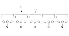
- FIG. 8 is a cross-sectional view showing a main part of the solar heat receiver according to the present embodiment.
- the solar heat receiver 41 according to this embodiment is different from that of the first embodiment described above in that a heat transfer tube 42 is provided instead of the heat transfer tube 16. Since other components are the same as those of the first embodiment described above, description of these components is omitted here.
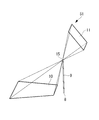
- the heat receiving surface 11 is matched with the planar view shape of the mirror arrangement surface 10 even when the ground surface (substantially) square shape cannot be secured as the mirror arrangement surface 10. Sunlight can be condensed on the solar heat receiver 51 simply by tilting.
- Other functions and effects are the same as those of the first to fourth embodiments described above, and thus the description thereof is omitted here.
Landscapes
- Engineering & Computer Science (AREA)
- Life Sciences & Earth Sciences (AREA)
- Sustainable Development (AREA)
- Sustainable Energy (AREA)
- Chemical & Material Sciences (AREA)
- Combustion & Propulsion (AREA)
- Mechanical Engineering (AREA)
- General Engineering & Computer Science (AREA)
- Physics & Mathematics (AREA)
- Thermal Sciences (AREA)
- Engine Equipment That Uses Special Cycles (AREA)
Abstract
Description
また、上記特許文献1の第5図に開示された太陽熱受熱器1では、複数の伝熱管14が円筒形に配置されることになるため、これら伝熱管14を支持する支持構造が複雑化し、製造コストが高騰するといった問題点もあった。
本発明に係る太陽熱受熱器は、南北方向に沿って配列された複数本の伝熱管と、これら伝熱管を収容するとともに、地盤に配置された集光器で集められた太陽光を前記伝熱管の下面側から導入する太陽熱入口が形成されたケーシングとを備え、前記地盤に立設されたタワーの頂部に配置されてなる太陽熱受熱器であって、前記集光器が配置されたミラー配置面と平行な受熱面、または前記集光器が配置されたミラー配置面に対して傾斜した受熱面に、前記伝熱管が等間隔に配置されており、前記伝熱管の管径が、前記太陽熱入口から各伝熱管の長手方向に沿う中心軸線までの最短距離に概ね反比例するように設定されている。
これにより、各伝熱管内を通過する圧縮性作動流体を一様に(均一に)加熱することができ、各伝熱管から流出する圧縮性作動流体の温度を一様に(均一に)する(揃える)ことができる。
また、伝熱管は、ミラー配置面と平行な受熱面、すなわち、平坦面に沿って配列されることとなるので、伝熱管を支持する支持構造の簡略化を図ることができ、製造コストを低落させることができる。
これにより、各伝熱管内を通過する圧縮性作動流体を一様に(均一に)加熱することができ、各伝熱管から流出する圧縮性作動流体の温度を一様に(均一に)する(揃える)ことができる。
また、伝熱管は、配列方向(東西方向)における中央部が太陽熱入口と反対の側に向かって突出する湾曲面に沿って配列されることとなるので、伝熱管を支持する支持構造の簡略化を図ることができ、製造コストを低落させることができる。
さらに、伝熱管は、同一の管径を有するものだけですむ(同一の管径を有するものだけで構成されることとなる)ので、伝熱管を支持する支持構造の簡略化をさらに図ることができ、製造コストをさらに低落させることができる。
これにより、各伝熱管内を通過する圧縮性作動流体を一様に(均一に)加熱することができ、各伝熱管から流出する圧縮性作動流体の温度を一様に(均一に)する(揃える)ことができる。
また、伝熱管は、ミラー配置面と平行な受熱面、すなわち、平坦面に沿って配列されることとなるので、伝熱管を支持する支持構造の簡略化を図ることができ、製造コストを低落させることができる。
さらに、伝熱管は、同一の管径を有するものだけですむ(同一の管径を有するものだけで構成されることとなる)ので、伝熱管を支持する支持構造の簡略化をさらに図ることができ、製造コストをさらに低落させることができる。
これにより、各伝熱管内を通過する圧縮性作動流体を一様に(均一に)加熱することができ、各伝熱管から流出する圧縮性作動流体の温度を一様に(均一に)する(揃える)ことができて、太陽熱受熱器からタービンに送られる圧縮性作動流体の温度を従来よりも上昇させることができ、タービン効率を従来よりも向上させることができる。
また、伝熱管は、ミラー配置面と平行な受熱面、すなわち、平坦面に沿って配列されることとなるので、伝熱管を支持する支持構造の簡略化を図ることができ、製造コストを低落させることができる。
さらに、伝熱管は、同一の管径を有するものだけですむ(同一の管径を有するものだけで構成されることとなる)ので、伝熱管を支持する支持構造の簡略化をさらに図ることができ、製造コストをさらに低落させることができる。
3 太陽熱受熱器
8 地盤
9 タワー
10 ミラー配置面
10a 一辺
11 受熱面
12 集光器
14 ケーシング
15 太陽熱入口
16 伝熱管
16a 伝熱管
16b 伝熱管
21 太陽熱受熱器
22 受熱面
22a 第1の辺
22b 第2の辺
23 伝熱管
31 太陽熱受熱器
32 伝熱管
41 太陽熱受熱器
42 伝熱管
51 太陽熱受熱器
100 太陽熱ガスタービン発電装置
図1は本実施形態に係る太陽熱受熱器を具備した太陽熱ガスタービンおよび太陽熱ガスタービン発電装置の概略構成図、図2は本実施形態に係る太陽熱受熱器と、この太陽熱受熱器に太陽光を集光させる集光器が配置されたミラー配置面との関係を説明するための図、図3は集光器の概要を説明するための図、図4は本実施形態に係る太陽熱受熱器の内部を示す概略構成図である。
なお、図中の符号6は、タービン4で仕事をした後に煙突7から大気へ排出される圧縮性作動流体の排熱を用い、圧縮機2で昇圧された高圧の圧縮性作動流体を予熱するための再熱器である。
なお、図4中の符号17は、伝熱管16の背後(太陽熱入口15と反対の側)で、ケーシング14の頂部内面に配置された断熱材である。
これにより、各伝熱管16内を通過する圧縮性作動流体を一様に(均一に)加熱することができ、各伝熱管16から流出する圧縮性作動流体の温度を一様に(均一に)する(揃える)ことができる。
これにより、各伝熱管16内を通過する圧縮性作動流体を一様に(均一に)加熱することができ、各伝熱管16から流出する圧縮性作動流体の温度を一様に(均一に)する(揃える)ことができる。
また、伝熱管16は、ミラー配置面10と平行な受熱面11、すなわち、平坦面に沿って配列されることとなるので、伝熱管16を支持する支持構造の簡略化を図ることができ、製造コストを低落させることができる。
図5は本実施形態に係る太陽熱受熱器と、この太陽熱受熱器に太陽光を集光させる集光器が配置されたミラー配置面との関係を説明するための図、図6は本実施形態に係る太陽熱受熱器の内部を示す概略構成図である。
なお、第1の辺22aの一端と第2の辺22bの一端とは、直線からなる第3の辺22cで結ばれており、第1の辺22aの他端と第2の辺22bの他端とは、直線からなる第4の辺22d(図6参照)で結ばれている。
これにより、各伝熱管23内を通過する圧縮性作動流体を一様に(均一に)加熱することができ、各伝熱管23から流出する圧縮性作動流体の温度を一様に(均一に)する(揃える)ことができる。
また、伝熱管23は、配列方向(東西方向)における中央部が太陽熱入口15と反対の側に向かって突出する湾曲面に沿って配列されることとなるので、伝熱管23を支持する支持構造の簡略化を図ることができ、製造コストを低落させることができる。
さらに、伝熱管23は、同一の管径を有するものだけですむ(同一の管径を有するものだけで構成されることとなる)ので、伝熱管23を支持する支持構造の簡略化をさらに図ることができ、製造コストをさらに低落させることができる。
図7は本実施形態に係る太陽熱受熱器の要部を示す断面図である。
図7に示すように、本実施形態に係る太陽熱受熱器31は、伝熱管16の代わりに伝熱管32が設けられているという点で上述した第1実施形態のものと異なる。その他の構成要素については上述した第1実施形態のものと同じであるので、ここではそれら構成要素についての説明は省略する。
これにより、各伝熱管32内を通過する圧縮性作動流体を一様に(均一に)加熱することができ、各伝熱管32から流出する圧縮性作動流体の温度を一様に(均一に)する(揃える)ことができる。
また、伝熱管32は、ミラー配置面10と平行な受熱面11、すなわち、平坦面に沿って配列されることとなるので、伝熱管32を支持する支持構造の簡略化を図ることができ、製造コストを低落させることができる。
さらに、伝熱管32は、同一の管径を有するものだけですむ(同一の管径を有するものだけで構成されることとなる)ので、伝熱管32を支持する支持構造の簡略化をさらに図ることができ、製造コストをさらに低落させることができる。
図8は本実施形態に係る太陽熱受熱器の要部を示す断面図である。
図8に示すように、本実施形態に係る太陽熱受熱器41は、伝熱管16の代わりに伝熱管42が設けられているという点で上述した第1実施形態のものと異なる。その他の構成要素については上述した第1実施形態のものと同じであるので、ここではそれら構成要素についての説明は省略する。
また、伝熱管42は、同一の管径を有するものだけですむ(同一の管径を有するものだけで構成されることとなる)ので、伝熱管42を支持する支持構造の簡略化をさらに図ることができ、製造コストをさらに低落させることができる。
これにより、各伝熱管42内を通過する圧縮性作動流体を一様に(均一に)加熱することができ、各伝熱管42から流出する圧縮性作動流体の温度を一様に(均一に)する(揃える)ことができて、太陽熱受熱器41からタービン4に送られる圧縮性作動流体の温度を従来よりも上昇させることができ、タービン効率を従来よりも向上させることができる。
図9は本実施形態に係る太陽熱受熱器と、この太陽熱受熱器に太陽光を集光させる集光器が配置されたミラー配置面との関係を説明するための図である。
その他の作用効果は、上述した第1実施形態から第4実施形態のものと同じであるので、ここではその説明は省略する。
Claims (6)
- 南北方向に沿って配列された複数本の伝熱管と、これら伝熱管を収容するとともに、地盤に配置された集光器で集められた太陽光を前記伝熱管の下面側から導入する太陽熱入口が形成されたケーシングとを備え、前記地盤に立設されたタワーの頂部に配置されてなる太陽熱受熱器であって、
前記集光器が配置されたミラー配置面と平行な受熱面、または前記集光器が配置されたミラー配置面に対して傾斜した受熱面に、前記伝熱管が等間隔に配置されており、前記伝熱管の管径が、前記太陽熱入口から各伝熱管の長手方向に沿う中心軸線までの最短距離に概ね反比例するように設定されていることを特徴とする太陽熱受熱器。 - 南北方向に沿って配列されるとともに、同一の管径を有する複数本の伝熱管と、これら伝熱管を収容するとともに、地盤に配置された集光器で集められた太陽光を前記伝熱管の下面側から導入する太陽熱入口が形成されたケーシングとを備え、前記地盤に立設されたタワーの頂部に配置されてなる太陽熱受熱器であって、
北半球においては南端を、南半球においては北端を形成する第1の辺、および北半球においては北端を、南半球においては南端を形成する第2の辺が、前記太陽熱入口と反対の側に向かって凹むとともに、前記太陽熱入口から前記第1の辺までの距離、および前記太陽熱入口から前記第2の辺までの距離がそれぞれ同じになるように設定された受熱面に、前記伝熱管が等間隔に配置されていることを特徴とする太陽熱受熱器。 - 南北方向に沿って配列されるとともに、同一の管径を有する複数本の伝熱管と、これら伝熱管を収容するとともに、地盤に配置された集光器で集められた太陽光を前記伝熱管の下面側から導入する太陽熱入口が形成されたケーシングとを備え、前記地盤に立設されたタワーの頂部に配置されてなる太陽熱受熱器であって、
前記集光器が配置されたミラー配置面と平行な受熱面、または前記集光器が配置されたミラー配置面に対して傾斜した受熱面に、前記伝熱管が配置されており、前記太陽熱入口を対称の中心として点対称の位置にある、北半球においては南端に、南半球においては北端に位置する前記ミラー配置面の一辺上に配置された前記集光器までの最短距離に概ね比例するように、前記伝熱管の間隔が設定されていることを特徴とする太陽熱受熱器。 - 請求項1から3のいずれか一項に記載の太陽熱受熱器を具備してなることを特徴とする太陽熱ガスタービン。
- 地盤に設定されたミラー配置面に配置されてなる集光器と、
南北方向に沿って配列されるとともに、同一の管径を有する複数本の伝熱管と、これら伝熱管を収容するとともに、前記集光器で集められた太陽光を前記伝熱管の下面側から導入する太陽熱入口が形成されたケーシングとを備え、前記地盤に立設されたタワーの頂部に配置されてなる太陽熱受熱器とを備えた太陽熱ガスタービンであって、
前記集光器が配置されたミラー配置面と平行な受熱面、または前記集光器が配置されたミラー配置面に対して傾斜した受熱面に、前記伝熱管が等間隔に配置されており、前記太陽熱入口を対称の中心として点対称の位置にある、北半球においては南端に、南半球においては北端に位置する前記ミラー配置面の一辺上に配置された前記集光器までの最短距離に概ね反比例するように、前記集光器の東西方向の間隔が設定されていることを特徴とする太陽熱ガスタービン。 - 請求項4または5に記載の太陽熱ガスタービンを具備してなることを特徴とする太陽熱ガスタービン発電装置。
Priority Applications (5)
| Application Number | Priority Date | Filing Date | Title |
|---|---|---|---|
| JP2011518539A JP5145461B2 (ja) | 2009-06-09 | 2010-06-08 | 太陽熱受熱器 |
| US13/124,963 US20110239651A1 (en) | 2009-06-09 | 2010-06-08 | Solar central receiver |
| EP10786153A EP2442047A1 (en) | 2009-06-09 | 2010-06-08 | Solar heat receiver |
| AU2010259633A AU2010259633A1 (en) | 2009-06-09 | 2010-06-08 | Solar central receiver |
| ZA2011/03089A ZA201103089B (en) | 2009-06-09 | 2011-04-26 | Solar central receiver |
Applications Claiming Priority (2)
| Application Number | Priority Date | Filing Date | Title |
|---|---|---|---|
| JP2009138576 | 2009-06-09 | ||
| JP2009-138576 | 2009-06-09 |
Publications (1)
| Publication Number | Publication Date |
|---|---|
| WO2010143622A1 true WO2010143622A1 (ja) | 2010-12-16 |
Family
ID=43308877
Family Applications (1)
| Application Number | Title | Priority Date | Filing Date |
|---|---|---|---|
| PCT/JP2010/059674 Ceased WO2010143622A1 (ja) | 2009-06-09 | 2010-06-08 | 太陽熱受熱器 |
Country Status (6)
| Country | Link |
|---|---|
| US (1) | US20110239651A1 (ja) |
| EP (1) | EP2442047A1 (ja) |
| JP (1) | JP5145461B2 (ja) |
| AU (1) | AU2010259633A1 (ja) |
| WO (1) | WO2010143622A1 (ja) |
| ZA (1) | ZA201103089B (ja) |
Cited By (1)
| Publication number | Priority date | Publication date | Assignee | Title |
|---|---|---|---|---|
| WO2013094731A1 (ja) * | 2011-12-22 | 2013-06-27 | 三菱重工業株式会社 | 太陽熱受熱器、その組立方法、および太陽熱受熱器を備えた太陽熱発電システム |
Families Citing this family (24)
| Publication number | Priority date | Publication date | Assignee | Title |
|---|---|---|---|---|
| US8596075B2 (en) | 2009-02-26 | 2013-12-03 | Palmer Labs, Llc | System and method for high efficiency power generation using a carbon dioxide circulating working fluid |
| US10018115B2 (en) | 2009-02-26 | 2018-07-10 | 8 Rivers Capital, Llc | System and method for high efficiency power generation using a carbon dioxide circulating working fluid |
| US20130118145A1 (en) * | 2011-11-11 | 2013-05-16 | 8 River Capital, LLC | Hybrid fossil fuel and solar heated supercritical carbon dioxide power generating system and method |
| MX358190B (es) | 2012-02-11 | 2018-08-08 | Palmer Labs Llc | Reaccion de oxidacion parcial con enfriamiento de ciclo cerrado. |
| US9347690B2 (en) | 2012-04-02 | 2016-05-24 | Alliance For Sustainable Energy, Llc | Methods and systems for concentrated solar power |
| US20140238386A1 (en) * | 2013-02-23 | 2014-08-28 | Alexander Levin | Radiation absorbing metal pipe |
| US9702348B2 (en) | 2013-04-03 | 2017-07-11 | Alliance For Sustainable Energy, Llc | Chemical looping fluidized-bed concentrating solar power system and method |
| JP6250332B2 (ja) | 2013-08-27 | 2017-12-20 | 8 リバーズ キャピタル,エルエルシー | ガスタービン設備 |
| US9945585B2 (en) | 2014-05-15 | 2018-04-17 | Alliance For Sustainable Energy, Llc | Systems and methods for direct thermal receivers using near blackbody configurations |
| TWI657195B (zh) | 2014-07-08 | 2019-04-21 | 美商八河資本有限公司 | 加熱再循環氣體流的方法、生成功率的方法及功率產出系統 |
| US11231224B2 (en) | 2014-09-09 | 2022-01-25 | 8 Rivers Capital, Llc | Production of low pressure liquid carbon dioxide from a power production system and method |
| EP3438049B1 (en) | 2014-09-09 | 2021-11-03 | 8 Rivers Capital, LLC | Method of production of low pressure liquid carbon dioxide from a power production system |
| US11686258B2 (en) | 2014-11-12 | 2023-06-27 | 8 Rivers Capital, Llc | Control systems and methods suitable for use with power production systems and methods |
| MA40950A (fr) | 2014-11-12 | 2017-09-19 | 8 Rivers Capital Llc | Systèmes et procédés de commande appropriés pour une utilisation avec des systèmes et des procédés de production d'énergie |
| US10961920B2 (en) | 2018-10-02 | 2021-03-30 | 8 Rivers Capital, Llc | Control systems and methods suitable for use with power production systems and methods |
| KR102602774B1 (ko) | 2015-06-15 | 2023-11-15 | 8 리버스 캐피탈, 엘엘씨 | 동력 생산 플랜트의 기동을 위한 시스템 및 방법 |
| US10422552B2 (en) | 2015-12-24 | 2019-09-24 | Alliance For Sustainable Energy, Llc | Receivers for concentrating solar power generation |
| MX2018010022A (es) | 2016-02-18 | 2018-12-10 | 8 Rivers Capital Llc | Sistema y metodo para la produccion de energia incluyendo metanacion. |
| JP7001608B2 (ja) | 2016-02-26 | 2022-01-19 | 8 リバーズ キャピタル,エルエルシー | 電力プラントを制御するためのシステムおよび方法 |
| MX2019002888A (es) | 2016-09-13 | 2019-07-04 | 8 Rivers Capital Llc | Sistema y metodo para la produccion de energia utilizando oxidacion parcial. |
| BR112020003886A2 (pt) | 2017-08-28 | 2020-09-01 | 8 Rivers Capital, Llc | otimização de calor de baixo grau de ciclos de energia de co2 supercrítico recuperável |
| PL3759322T3 (pl) | 2018-03-02 | 2024-03-18 | 8 Rivers Capital, Llc | Układy i sposoby wytwarzania energii z wykorzystaniem płynu roboczego z dwutlenku węgla |
| CA3155211A1 (en) | 2019-10-22 | 2021-04-29 | Brock Alan Forrest | Control schemes for thermal management of power production systems and methods |
| US12352249B1 (en) * | 2023-06-29 | 2025-07-08 | Jon McWhirter | Hybrid thermodynamic cycle with isothermal heat addition via concentrated solar power array |
Citations (2)
| Publication number | Priority date | Publication date | Assignee | Title |
|---|---|---|---|---|
| JPH0252953A (ja) | 1988-08-12 | 1990-02-22 | Toshiba Corp | 受蓄熱器 |
| WO2009029277A2 (en) * | 2007-08-27 | 2009-03-05 | Ausra, Inc. | Linear fresnel solar arrays |
Family Cites Families (3)
| Publication number | Priority date | Publication date | Assignee | Title |
|---|---|---|---|---|
| US4164123A (en) * | 1976-08-25 | 1979-08-14 | Smith Otto J M | Solar thermal electric power plant |
| US4162825A (en) * | 1977-08-05 | 1979-07-31 | Ford Aerospace & Communications Corp. | Method for adjusting the radius of curvature of a spherical mirror |
| US4414812A (en) * | 1981-04-30 | 1983-11-15 | R & D Associates | Hot air solar engine |
-
2010
- 2010-06-08 JP JP2011518539A patent/JP5145461B2/ja not_active Expired - Fee Related
- 2010-06-08 EP EP10786153A patent/EP2442047A1/en not_active Withdrawn
- 2010-06-08 WO PCT/JP2010/059674 patent/WO2010143622A1/ja not_active Ceased
- 2010-06-08 US US13/124,963 patent/US20110239651A1/en not_active Abandoned
- 2010-06-08 AU AU2010259633A patent/AU2010259633A1/en not_active Abandoned
-
2011
- 2011-04-26 ZA ZA2011/03089A patent/ZA201103089B/en unknown
Patent Citations (2)
| Publication number | Priority date | Publication date | Assignee | Title |
|---|---|---|---|---|
| JPH0252953A (ja) | 1988-08-12 | 1990-02-22 | Toshiba Corp | 受蓄熱器 |
| WO2009029277A2 (en) * | 2007-08-27 | 2009-03-05 | Ausra, Inc. | Linear fresnel solar arrays |
Cited By (2)
| Publication number | Priority date | Publication date | Assignee | Title |
|---|---|---|---|---|
| WO2013094731A1 (ja) * | 2011-12-22 | 2013-06-27 | 三菱重工業株式会社 | 太陽熱受熱器、その組立方法、および太陽熱受熱器を備えた太陽熱発電システム |
| AU2012354665B2 (en) * | 2011-12-22 | 2015-10-15 | Mitsubishi Heavy Industries, Ltd. | Solar heat receiver, method for assembling same, and solar heat power generation system with solar heat receiver |
Also Published As
| Publication number | Publication date |
|---|---|
| ZA201103089B (en) | 2012-04-25 |
| AU2010259633A1 (en) | 2010-12-16 |
| JP5145461B2 (ja) | 2013-02-20 |
| US20110239651A1 (en) | 2011-10-06 |
| EP2442047A1 (en) | 2012-04-18 |
| JPWO2010143622A1 (ja) | 2012-11-22 |
Similar Documents
| Publication | Publication Date | Title |
|---|---|---|
| JP5145461B2 (ja) | 太陽熱受熱器 | |
| CN106030218A (zh) | 用于太阳能收集器的线性接收器 | |
| JP2010286200A (ja) | 太陽熱集光器 | |
| WO2011096339A1 (ja) | 太陽熱受熱器 | |
| US20110289921A1 (en) | Flag-shaped heat exchanger | |
| JP2011007149A (ja) | ガスタービンプラント | |
| WO2012073676A1 (ja) | 太陽熱受熱器 | |
| CN103673320A (zh) | 太阳集热装置 | |
| EP2427700B1 (en) | Getter support structure for a solar thermal power plant | |
| US20130213388A1 (en) | Coil solar receiver for a stirling disk and method for manufacturing same | |
| CN103842739B (zh) | 太阳辐射接收器 | |
| US9080790B2 (en) | Concave receiver for stirling dish and method for manufacturing the same | |
| KR20070022498A (ko) | 굴곡된 형상을 갖는 진공관형 태양열 집열기의 집열판 | |
| KR101290110B1 (ko) | 태양열 판형상 집열기를 이용한 캡형 온수공급장치 | |
| CN101956968B (zh) | 塔式太阳能自然循环接收器 | |
| JP2011007150A (ja) | 受熱器 | |
| Muhammad Ali et al. | Analyzing the impact of various receiver types on the thermal performance of a parabolic trough solar collector | |
| JP2011163592A (ja) | 太陽熱受熱器 | |
| Khokhar et al. | A Research: High Efficiency Solar Thermal Power Plant | |
| CN206724498U (zh) | 一种太阳能集热器 | |
| JP2010286199A (ja) | 太陽熱受熱器 | |
| JP2011220557A (ja) | 太陽熱受熱器 | |
| US20140238386A1 (en) | Radiation absorbing metal pipe | |
| JP2011163595A (ja) | 太陽熱受熱器 | |
| JP2012117394A (ja) | 太陽熱受熱器 |
Legal Events
| Date | Code | Title | Description |
|---|---|---|---|
| 121 | Ep: the epo has been informed by wipo that ep was designated in this application |
Ref document number: 10786153 Country of ref document: EP Kind code of ref document: A1 |
|
| WWE | Wipo information: entry into national phase |
Ref document number: 2010786153 Country of ref document: EP |
|
| ENP | Entry into the national phase |
Ref document number: 2011518539 Country of ref document: JP Kind code of ref document: A |
|
| WWE | Wipo information: entry into national phase |
Ref document number: 2692/CHENP/2011 Country of ref document: IN |
|
| ENP | Entry into the national phase |
Ref document number: 2010259633 Country of ref document: AU Date of ref document: 20100608 Kind code of ref document: A |
|
| WWE | Wipo information: entry into national phase |
Ref document number: 13124963 Country of ref document: US |
|
| NENP | Non-entry into the national phase |
Ref country code: DE |