WO2010143549A1 - 画像処理装置および方法、並びにプログラム - Google Patents
画像処理装置および方法、並びにプログラム Download PDFInfo
- Publication number
- WO2010143549A1 WO2010143549A1 PCT/JP2010/059177 JP2010059177W WO2010143549A1 WO 2010143549 A1 WO2010143549 A1 WO 2010143549A1 JP 2010059177 W JP2010059177 W JP 2010059177W WO 2010143549 A1 WO2010143549 A1 WO 2010143549A1
- Authority
- WO
- WIPO (PCT)
- Prior art keywords
- image
- input image
- unit
- edge
- value
- Prior art date
- Legal status (The legal status is an assumption and is not a legal conclusion. Google has not performed a legal analysis and makes no representation as to the accuracy of the status listed.)
- Ceased
Links
Images










Classifications
-
- G—PHYSICS
- G06—COMPUTING OR CALCULATING; COUNTING
- G06T—IMAGE DATA PROCESSING OR GENERATION, IN GENERAL
- G06T7/00—Image analysis
-
- H—ELECTRICITY
- H04—ELECTRIC COMMUNICATION TECHNIQUE
- H04N—PICTORIAL COMMUNICATION, e.g. TELEVISION
- H04N17/00—Diagnosis, testing or measuring for television systems or their details
- H04N17/002—Diagnosis, testing or measuring for television systems or their details for television cameras
-
- G—PHYSICS
- G06—COMPUTING OR CALCULATING; COUNTING
- G06T—IMAGE DATA PROCESSING OR GENERATION, IN GENERAL
- G06T7/00—Image analysis
- G06T7/0002—Inspection of images, e.g. flaw detection
-
- H—ELECTRICITY
- H04—ELECTRIC COMMUNICATION TECHNIQUE
- H04N—PICTORIAL COMMUNICATION, e.g. TELEVISION
- H04N17/00—Diagnosis, testing or measuring for television systems or their details
-
- H—ELECTRICITY
- H04—ELECTRIC COMMUNICATION TECHNIQUE
- H04N—PICTORIAL COMMUNICATION, e.g. TELEVISION
- H04N23/00—Cameras or camera modules comprising electronic image sensors; Control thereof
- H04N23/60—Control of cameras or camera modules
- H04N23/64—Computer-aided capture of images, e.g. transfer from script file into camera, check of taken image quality, advice or proposal for image composition or decision on when to take image
-
- G—PHYSICS
- G06—COMPUTING OR CALCULATING; COUNTING
- G06T—IMAGE DATA PROCESSING OR GENERATION, IN GENERAL
- G06T2207/00—Indexing scheme for image analysis or image enhancement
- G06T2207/10—Image acquisition modality
- G06T2207/10024—Color image
-
- G—PHYSICS
- G06—COMPUTING OR CALCULATING; COUNTING
- G06T—IMAGE DATA PROCESSING OR GENERATION, IN GENERAL
- G06T2207/00—Indexing scheme for image analysis or image enhancement
- G06T2207/20—Special algorithmic details
- G06T2207/20016—Hierarchical, coarse-to-fine, multiscale or multiresolution image processing; Pyramid transform
-
- G—PHYSICS
- G06—COMPUTING OR CALCULATING; COUNTING
- G06T—IMAGE DATA PROCESSING OR GENERATION, IN GENERAL
- G06T2207/00—Indexing scheme for image analysis or image enhancement
- G06T2207/20—Special algorithmic details
- G06T2207/20021—Dividing image into blocks, subimages or windows
-
- G—PHYSICS
- G06—COMPUTING OR CALCULATING; COUNTING
- G06T—IMAGE DATA PROCESSING OR GENERATION, IN GENERAL
- G06T2207/00—Indexing scheme for image analysis or image enhancement
- G06T2207/30—Subject of image; Context of image processing
- G06T2207/30168—Image quality inspection
-
- G—PHYSICS
- G06—COMPUTING OR CALCULATING; COUNTING
- G06T—IMAGE DATA PROCESSING OR GENERATION, IN GENERAL
- G06T2207/00—Indexing scheme for image analysis or image enhancement
- G06T2207/30—Subject of image; Context of image processing
- G06T2207/30196—Human being; Person
- G06T2207/30201—Face
Definitions
- the present invention relates to an image processing apparatus, method, and program, and more particularly, to an image processing apparatus, method, and program that can more appropriately evaluate the degree of shooting of a captured image.
- the feature amount of each feature is extracted from the entire image, the evaluation for the image is obtained for each feature, and the evaluation for each feature is totaled.
- evaluation for example, refer nonpatent literature 1.
- an evaluation based on the complexity of the edge, the size of the bounding box, the degree of blur, and the like is calculated as the evaluation for each feature.
- an image with a simple background portion that is, an image with an uncomplicated edge in the background portion is considered to be well taken and is regarded as a highly evaluated image.
- a general highly evaluated image in which the area of the subject portion on the image is large and the subject portion has a complicated edge, but the background portion does not have a complicated edge.
- the edge strength is extracted from the image and the evaluation based on the complexity of the edge is obtained, since the edge is considered to be complicated in the entire image, the obtained evaluation value is originally obtained. The evaluation will be lower than expected.
- the present invention has been made in view of such circumstances, and makes it possible to more appropriately evaluate the degree of image capture.
- An image processing apparatus extracts a feature amount of a first feature from an entire input image, and applies the input feature based on the first feature to the input image based on the feature amount of the first feature.
- a first evaluation value calculating means for calculating a first partial evaluation value indicating evaluation; a feature amount of a second feature is extracted from a predetermined region of the input image; and based on the feature amount of the second feature
- a second evaluation value calculating means for calculating a second partial evaluation value indicating an evaluation of the input image based on the second feature, and the first partial evaluation value and the second partial evaluation value.
- a comprehensive evaluation value calculating means for calculating a comprehensive evaluation value indicating the evaluation of the shooting condition of the input image.
- the second partial evaluation value calculating means extracts the feature amount of the third feature of the subject area on the input image from each area of the input image, thereby extracting the feature of the subject on the input image. From the subject area specifying means for specifying the area and any one of a subject area that includes the subject on the input image or a background area that does not include the subject on the input image. A calculating means for extracting a feature amount and calculating the second partial evaluation value can be provided.
- the calculation means extracts a brightness value in each area in the subject area on the input image as a feature amount of the second feature, and the second value based on the distribution of the brightness value in the subject area A partial evaluation value can be calculated.
- the calculating means is configured to extract an edge strength in each region in the background region on the input image as a feature amount of the second feature, and to calculate the second feature based on the complexity of the edge in the background region. A partial evaluation value can be calculated.
- the first evaluation value calculation means includes the first partial evaluation value based on at least one of a degree of blur, a color distribution, a saturation average, and a saturation dispersion in the entire input image. Can be calculated.
- the comprehensive evaluation value calculating means adds a value predetermined for the value of the first partial evaluation value and a value predetermined for the value of the second partial evaluation value. Thus, the comprehensive evaluation value can be calculated.
- the value predetermined for the value of the first partial evaluation value is determined based on the first partial evaluation value of a plurality of images obtained in advance and having different evaluations of shooting conditions
- a value predetermined for the value of the second partial evaluation value is determined based on the second partial evaluation value of a plurality of images that are obtained in advance and have different evaluation of shooting conditions. be able to.
- the image processing method or program extracts a feature amount of a first feature from the entire input image, and the input based on the first feature based on the feature amount of the first feature.
- a first partial evaluation value indicating evaluation of the image is calculated, a feature amount of the second feature is extracted from a predetermined area of the input image, and the second feature value is extracted based on the feature amount of the second feature.
- a second partial evaluation value indicating an evaluation of the input image based on a feature is calculated, and an overall evaluation indicating an evaluation of a shooting condition of the input image is performed based on the first partial evaluation value and the second partial evaluation value. Calculating an evaluation value.
- a feature amount of a first feature is extracted from the entire input image, and evaluation of the input image based on the first feature is shown based on the feature amount of the first feature.
- a first partial evaluation value is calculated, a feature amount of a second feature is extracted from a predetermined region of the input image, and the input based on the second feature is based on the feature amount of the second feature.
- a second partial evaluation value indicating the evaluation of the image is calculated, and a comprehensive evaluation value indicating an evaluation of the shooting condition of the input image is calculated based on the first partial evaluation value and the second partial evaluation value.
- FIG. 1 It is a figure which shows the structural example of one Embodiment of the image processing apparatus to which this invention is applied. It is a figure which shows the structural example of a blurring degree score calculation part. It is a figure which shows the structural example of a brightness
- FIG. 1 is a diagram showing a configuration example of an embodiment of an image processing apparatus to which the present invention is applied.
- This image processing apparatus 11 evaluates whether or not the input image is taken well with respect to the input image obtained by imaging with an imaging device such as a camera, that is, how the input image is captured (the appearance of the input image).
- An evaluation value (hereinafter referred to as a total score) is calculated.
- the evaluation of the input image becomes higher as the input image is closer to an image taken by a photographic specialist, and the total score value of the input image becomes smaller. In other words, an input image with a smaller total score value is considered to be a better image.
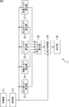
- the image processing apparatus 11 includes a recording unit 21, an acquisition unit 22, a blur score calculation unit 23, a luminance score calculation unit 24, an edge score calculation unit 25, a color distribution score calculation unit 26, a saturation score calculation unit 27, and a total score calculation.
- the unit 28, the display control unit 29, and the display unit 30 are configured.
- the recording unit 21 includes a hard disk or the like, and records a plurality of input images picked up by the user with the image pickup apparatus.
- the input image is an image in which each pixel has R (red), G (green), and B (blue) component values as pixel values.
- the acquisition unit 22 acquires an input image from the recording unit 21 and supplies the input image to the blur score calculation unit 23 to the saturation score calculation unit 27 and the display control unit 29.
- the blur score calculation unit 23 to the saturation score calculation unit 27 extract a feature amount of a predetermined feature from the input image supplied from the acquisition unit 22, and indicate the evaluation for the input image based on the feature. Calculate another score.
- the blur degree score calculation unit 23 extracts edge strength from the input image as a feature amount of a predetermined feature, and calculates a blur degree score indicating the degree of blur of the input image based on the edge strength.
- the luminance score calculation unit 24 extracts a luminance value from the input image as a feature amount of a predetermined feature, and evaluates based on the luminance value distribution in the subject portion (foreground portion) of the input image based on the luminance value. A luminance score indicating is calculated.
- the edge score calculation unit 25 extracts edge strength from the input image as a feature amount of a predetermined feature, and based on the edge strength, an edge score indicating evaluation based on edge complexity in the background portion of the input image Is calculated.
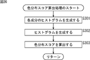
- the color distribution score calculation unit 26 extracts a component of each color from the input image as a feature amount of a predetermined feature, and based on the color component, a color distribution score indicating evaluation based on the color distribution in the input image Is calculated.
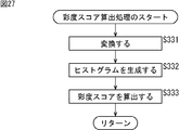
- the saturation score calculation unit 27 extracts saturation from the input image as a feature amount of a predetermined feature, and indicates evaluation based on the average and variance of the saturation distribution in the input image based on the saturation. Calculate the saturation score.
- the blur degree score calculation unit 23 to the saturation score calculation unit 27 supply the calculated blur degree score, luminance score, edge score, color distribution score, and saturation score to the total score calculation unit 28.
- the blur score, the luminance score, the edge score, the color distribution score, and the saturation score are also simply referred to as feature-specific scores when it is not necessary to distinguish them.
- the total score calculation unit 28 calculates a total score based on the feature-specific scores supplied from the blur score calculation unit 23 to the saturation score calculation unit 27 and supplies the total score to the display control unit 29. Based on the total score from the total score calculation unit 28, the display control unit 29 selects some input images with high evaluation among the input images supplied from the acquisition unit 22. Further, the display control unit 29 supplies the selected input image to the display unit 30 and controls the display of the input image.
- the display unit 30 includes, for example, a liquid crystal display, and displays an input image according to the control of the display control unit 29.
- the blur degree score calculation unit 23 in FIG. 1 is configured as shown in FIG. 2 in more detail.
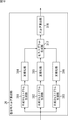
- the blur degree score calculation unit 23 includes an edge map generation unit 61, a dynamic range detection unit 62, a calculation parameter adjustment unit 63, a local max generation unit 64, an edge point extraction unit 65, an extraction amount determination unit 66, and an edge analysis unit 67. And a degree-of-blur detection unit 68.
- the edge map generation unit 61 Based on the input image supplied from the acquisition unit 22, the edge map generation unit 61 detects the edge strength (edge strength) of the input image in units of three types of blocks having different sizes, and determines the detected edge strength. An edge map is generated as pixel values. This edge map is generated for each block size, and is set as an edge map of scale SC1 to SC3 in order from the smallest block. The edge map generation unit 61 supplies the generated three edge maps to the dynamic range detection unit 62 and the local max generation unit 64.
- the dynamic range detection unit 62 uses the edge map from the edge map generation unit 61 to detect the dynamic range that is the difference between the maximum value and the minimum value of the edge strength of the input image, and the detection result is used as the calculation parameter adjustment unit 63. To supply.
- the calculation parameter adjustment unit 63 Based on the detection result supplied from the dynamic range detection unit 62, the calculation parameter adjustment unit 63 has an appropriate value for the edge point extraction amount (hereinafter also referred to as edge point extraction amount) used to detect the degree of blur in the input image.
- edge point extraction amount used to detect the degree of blur in the input image.
- the calculation parameters used for edge point extraction are adjusted so that Here, an edge point refers to a pixel that constitutes an edge in an image.
- calculation parameters include an edge reference value used for determining whether or not an edge point is used, and an extraction reference value used for determining whether or not an edge point extraction amount is appropriate.
- the calculation parameter adjustment unit 63 supplies the edge reference value to the edge point extraction unit 65 and the extraction amount determination unit 66, and supplies the extraction reference value to the extraction amount determination unit 66.
- the local max generator 64 divides the edge map supplied from the edge map generator 61 into blocks each having a predetermined size, and generates a local max by extracting the maximum pixel value of each block.
- the local max is generated for each scale of the edge map, and is supplied from the local max generating unit 64 to the edge point extracting unit 65 and the edge analyzing unit 67.
- the local maxes generated from the edge maps of the scales SC1 to SC3 are referred to as local max LM1 to local max LM3, respectively.
- the edge point extraction unit 65 extracts an edge point from the input image based on the edge reference value from the calculation parameter adjustment unit 63 and the local max from the local max generation unit 64. In addition, the edge point extraction unit 65 generates an edge point table indicating information on the extracted edge points, and supplies the edge point table to the extraction amount determination unit 66.
- the edge point tables obtained from the local max LM1 to the local max LM3 will be referred to as the edge point table ET1 to the edge point table ET3.
- the extraction amount determination unit 66 determines whether the edge point extraction amount is appropriate based on the edge point table from the edge point extraction unit 65 and the extraction reference value from the calculation parameter adjustment unit 63. When the edge point extraction amount is not appropriate, the extraction amount determination unit 66 notifies the calculation parameter adjustment unit 63 that the edge point extraction amount is not appropriate. When the edge point extraction amount is appropriate, the edge reference value at that time The edge point table is supplied to the edge analysis unit 67.
- the edge analysis unit 67 analyzes the edge point of the input image based on the edge point table from the extraction amount determination unit 66 and supplies the analysis result to the blur detection unit 68.
- the blur degree detection unit 68 detects a blur degree that is an index indicating the degree of blur of the input image based on the analysis result of the edge point, and supplies the blur degree to the total score calculation unit 28 as a blur degree score.
- the luminance score calculation unit 24 of FIG. 1 is configured as shown in FIG. 3 in more detail.
- the luminance score calculation unit 24 includes a subject extraction unit 91, a multiplication unit 92, a histogram generation unit 93, a normalization unit 94, and a score calculation unit 95.
- the input image from the acquisition unit 22 is an object extraction unit 91. And supplied to the multiplier 92.
- the subject extraction unit 91 generates a subject map for extracting a region including the subject in the input image based on the input image supplied from the acquisition unit 22 and supplies the subject map to the multiplication unit 92.
- the pixel value of the pixel of the subject map is “1” when the region of the input image at the same position as the pixel is estimated to be a region including the subject, and is at the same position as the pixel.
- the area of the input image is estimated to be an area that does not include the subject, it is set to “0”.
- the subject here is an object on the input image that is estimated to be noticed by the user when the user glances at the input image, that is, an object that is estimated to be looked at by the user. Therefore, the subject is not necessarily limited to a person.
- the multiplication unit 92 multiplies the pixel value of the pixel of the input image from the acquisition unit 22 by the pixel value of the pixel of the subject map from the subject extraction unit 91 to thereby obtain a subject image that is an image of the subject area in the input image. Is supplied to the histogram generator 93.
- the pixel value of the pixel of the subject portion is the same as the pixel value of the pixel of the input image at the same position as the pixel, and the pixel value of the background portion pixel not including the subject is 0 in the subject image.
- a subject area in the input image is specified (extracted) by multiplication processing in the multiplication unit 92, and a subject image including the portion of the subject is generated.
- the histogram generation unit 93 generates a histogram of luminance values of the subject image based on the subject image from the multiplication unit 92 and supplies the histogram to the normalization unit 94.
- the normalization unit 94 normalizes the histogram from the histogram generation unit 93 and supplies it to the score calculation unit 95. Further, the score calculation unit 95 calculates a luminance score based on the histogram supplied from the normalization unit 94 and supplies the luminance score to the total score calculation unit 28.
- the subject extraction unit 91 of FIG. 3 is configured as shown in FIG. 4 in more detail.
- the subject extraction unit 91 includes a luminance information extraction unit 121, a color information extraction unit 122, an edge information extraction unit 123, a face information extraction unit 124, and a subject map generation unit 125.
- the input image from the acquisition unit 22 is supplied to the luminance information extraction unit 121 to the face information extraction unit 124 of the subject extraction unit 91.
- the luminance information extraction unit 121 to the face information extraction unit 124 extract feature amounts of features that the subject region has more from the input image supplied from the acquisition unit 22, and determine the likelihood of the subject region in each region of the input image. Generate the information map shown.
- the luminance information extraction unit 121 extracts a luminance value from the input image, generates a luminance information map indicating information regarding luminance in each region of the input image, and supplies the luminance information map to the subject map generation unit 125.
- the color information extraction unit 122 extracts a predetermined color component from the input image, generates a color information map indicating information regarding the color in each area of the input image, and supplies the color information map to the subject map generation unit 125.
- the edge information extraction unit 123 extracts edge strength from the input image, generates an edge information map indicating information about the edge in each region of the input image, and supplies it to the subject map generation unit 125.
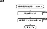
- the face information extraction unit 124 extracts a feature amount of a feature of a human face from the input image, generates a face information map indicating information related to the human face as a subject in each region of the input image, and generates a subject map. This is supplied to the generation unit 125.
- the luminance information map or the face information map output from the luminance information extraction unit 121 to the face information extraction unit 124 are also simply referred to as an information map.
- the information included in these information maps is information indicating the feature quantities of features that are included more in the area including the subject, and the information map is obtained by arranging the information corresponding to each area of the input image. The That is, the information map can be said to be information indicating the feature amount in each region of the input image.
- an area on the input image corresponding to a region with a larger amount of information in each information map, that is, a region with a larger amount of features, is a region with a higher possibility of including a subject. Can be specified.
- the subject map generation unit 125 linearly combines the information maps supplied from the luminance information extraction unit 121 to the face information extraction unit 124 to generate a subject map. That is, the subject map is generated by weighting and adding the information (feature amount) of each area of the luminance information map to the face information map for each area at the same position.
- the subject map generation unit 125 supplies the generated subject map to the multiplication unit 92.
- FIG. 5 is a diagram illustrating a more detailed configuration example of the luminance information extraction unit 121.
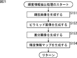
- the luminance information extraction unit 121 includes a luminance image generation unit 151, a pyramid image generation unit 152, a difference calculation unit 153, and a luminance information map generation unit 154.
- the luminance image generation unit 151 uses the input image supplied from the acquisition unit 22 to generate a luminance image having the luminance value of the pixel of the input image as the pixel value of the pixel, and supplies the luminance image to the pyramid image generation unit 152.
- the pixel value of an arbitrary pixel of the luminance image indicates the luminance value of the pixel of the input image at the same position as the pixel.
- the pyramid image generation unit 152 uses the luminance image supplied from the luminance image generation unit 151 to generate a plurality of luminance images having different resolutions, and supplies these luminance images to the difference calculation unit 153 as luminance pyramid images. To do.
- pyramid images of eight resolution layers from level L1 to level L8 are generated, the pyramid image of level L1 has the highest resolution, and the resolution of the pyramid image sequentially decreases from level L1 to level L8. .
- the luminance image generated by the luminance image generation unit 151 is a pyramid image of level L1.
- the pyramid image of level Li (where 1 ⁇ i ⁇ 7)
- the pyramid image at the level L (i + 1) is an image having a size that is half the length and width of the pyramid image at the level Li (truncated if not divisible).
- the difference calculation unit 153 selects two pyramid images having different hierarchies from among the plurality of pyramid images supplied from the pyramid image generation unit 152, obtains a difference between the selected pyramid images, and generates a luminance difference image. . Since the pyramid images in each layer have different sizes (number of pixels), the smaller pyramid image is up-converted in accordance with the larger pyramid image when generating the difference image.
- the difference calculation unit 153 When the difference calculation unit 153 generates a predetermined number of luminance difference images, the difference calculation unit 153 normalizes the generated difference images and supplies the normalized difference images to the luminance information map generation unit 154.
- the luminance information map generation unit 154 generates a luminance information map based on the difference image supplied from the difference calculation unit 153 and supplies the luminance information map to the subject map generation unit 125.
- FIG. 6 is a diagram illustrating a more detailed configuration example of the color information extraction unit 122 of FIG.
- the color information extraction unit 122 includes an RG difference image generation unit 181, a BY difference image generation unit 182, a pyramid image generation unit 183, a pyramid image generation unit 184, a difference calculation unit 185, a difference calculation unit 186, a color information map generation unit 187, And a color information map generation unit 188.
- the RG difference image generation unit 181 uses the input image supplied from the acquisition unit 22 to set the difference between the R (red) component and the G (green) component of the pixel of the input image as the pixel value of the pixel.
- An image is generated and supplied to the pyramid image generation unit 183.
- the pixel value of an arbitrary pixel of the RG difference image indicates a difference value between the R component and the G component of the pixel of the input image at the same position as the pixel.
- the BY difference image generation unit 182 uses the input image supplied from the acquisition unit 22, and uses the difference between the B (blue) component and Y (yellow) component of the pixel of the input image as the pixel value of the pixel.
- An image is generated and supplied to the pyramid image generation unit 184.
- the pixel value of an arbitrary pixel of the BY difference image indicates a difference value between the B (blue) component and the Y (yellow) component of the pixel of the input image at the same position as the pixel.
- the pyramid image generation unit 183 and the pyramid image generation unit 184 use a RG difference image and a BY difference image supplied from the RG difference image generation unit 181 and the BY difference image generation unit 182 to generate a plurality of RG difference images having different resolutions. And a BY difference image are generated. Then, the pyramid image generation unit 183 and the pyramid image generation unit 184 use the generated RG difference image and BY difference image as the RG difference pyramid image and the BY difference pyramid image, and the difference calculation unit 185 and difference calculation. To the unit 186.
- pyramid images of eight resolution layers from level L1 to level L8 are generated.
- the difference calculation unit 185 and the difference calculation unit 186 select two pyramid images having different hierarchies from among the plurality of pyramid images supplied from the pyramid image generation unit 183 and the pyramid image generation unit 184, and select the pyramid image of the selected pyramid image.
- the difference is obtained, and a difference image of RG difference and a difference image of BY difference are generated. Since the pyramid images of the respective layers have different sizes, the lower pyramid image is up-converted to have the same size as the larger pyramid image when the difference image is generated.
- the difference calculation unit 186 When the difference calculation unit 185 and the difference calculation unit 186 generate a difference image of RG differences and a difference image of BY differences by a predetermined number, the difference calculation unit 186 normalizes the generated difference images, and a color information map generation unit 187 and the color information map generation unit 188.
- the color information map generation unit 187 and the color information map generation unit 188 generate a color information map based on the difference images supplied from the difference calculation unit 185 and the difference calculation unit 186, and supply the color information map to the subject map generation unit 125.
- the color information map generation unit 187 generates a color information map of RG differences
- the color information map generation unit 188 generates a color information map of BY differences.
- FIG. 7 is a diagram illustrating a more detailed configuration example of the edge information extraction unit 123 of FIG.
- the edge information extraction unit 123 includes an edge image generation unit 211 to an edge image generation unit 214, a pyramid image generation unit 215 to a pyramid image generation unit 218, a difference calculation unit 219 to a difference calculation unit 222, and an edge information map generation unit 223 to an edge.
- the information map generation unit 226 is configured.
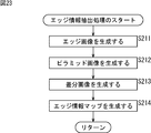
- the edge image generation unit 211 to the edge image generation unit 214 perform a filtering process using a Gabor filter on the input image supplied from the acquisition unit 22, for example, directions of 0 degrees, 45 degrees, 90 degrees, and 135 degrees
- An edge image having the edge intensity of the pixel as a pixel value is generated and supplied to the pyramid image generation unit 215 to the pyramid image generation unit 218.
- the pixel value of an arbitrary pixel of the edge image generated by the edge image generation unit 211 indicates the edge strength in the direction of 0 degree in the pixel of the input image at the same position as the pixel.
- the direction of each edge refers to a direction indicated by an angle component in a Gabor function that constitutes a Gabor filter.
- the pyramid image generation unit 215 through the pyramid image generation unit 218 generate a plurality of edge images having different resolutions using the edge images in the respective directions supplied from the edge image generation unit 211 through the edge image generation unit 214. Then, the pyramid image generation unit 215 through the pyramid image generation unit 218 supply the generated edge images in the respective directions to the difference calculation units 219 through 222 as pyramid images in the respective directions of the edges.
- the difference calculation unit 219 to the difference calculation unit 222 select two pyramid images having different hierarchies from among the plurality of pyramid images supplied from the pyramid image generation unit 215 to the pyramid image generation unit 218, and select the selected pyramid image. To obtain a difference image in each direction of the edge. Note that the pyramid images of the respective layers have different sizes, so that the smaller pyramid image is up-converted when the difference image is generated.
- the difference calculation unit 219 to the difference calculation unit 222 When the difference calculation unit 219 to the difference calculation unit 222 generate a difference image in each direction of the edge by a predetermined number, the generated difference images are normalized, and the edge information map generation unit 223 to the edge information map generation unit 226.
- the edge information map generation unit 223 through the edge information map generation unit 226 generate an edge information map in each direction based on the difference image supplied from the difference calculation unit 219 through the difference calculation unit 222, and sends it to the subject map generation unit 125. Supply.
- FIG. 8 is a diagram illustrating a more detailed configuration example of the face information extraction unit 124 of FIG.
- the face information extraction unit 124 includes a face detection unit 251 and a face information map generation unit 252.
- the face detection unit 251 detects a human face region as a subject from the input image supplied from the acquisition unit 22 and supplies the detection result to the face information map generation unit 252.
- the face information map generation unit 252 generates a face information map based on the detection result from the face detection unit 251 and supplies the face information map to the subject map generation unit 125.
- edge score calculation unit 25 in FIG. 1 is configured as shown in FIG. 9 in more detail.
- the edge score calculation unit 25 includes a subject extraction unit 281, an inversion unit 282, a filter processing unit 283, a normalization unit 284, a multiplication unit 285, a histogram generation unit 286, and a score calculation unit 287.
- the subject extraction unit 281 generates a subject map based on the input image supplied from the acquisition unit 22 and supplies the subject map to the inversion unit 282. Note that the subject extraction unit 281 has the same configuration as the subject extraction unit 91 in FIG.
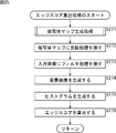
- the inversion unit 282 inverts the pixel value of the pixel of the subject map supplied from the subject extraction unit 281 and supplies it to the multiplication unit 285. That is, in the subject map, a pixel value of 1 is set to 0 for a pixel value, and a pixel value of 0 is set to 1 for a pixel value of the pixel. Therefore, the pixel value of the pixel of the object map after inversion is set to “0” when the area of the input image at the same position as the pixel is an area where the object is estimated to be included. When the area of the input image at the same position is an area estimated not to include the subject, “1” is set. That is, the inverted subject map is a map for specifying a background region that does not include the subject in the input image.
- the filter processing unit 283 generates a Laplacian image using the edge intensity in each region of the input image as the pixel value of the pixel by performing a filter process using a Laplacian filter on the input image supplied from the acquisition unit 22. It supplies to the normalization part 284.
- the normalization unit 284 normalizes the Laplacian image from the filter processing unit 283 and supplies it to the multiplication unit 285.
- the multiplication unit 285 multiplies the pixel value of the pixel of the Laplacian image from the normalization unit 284 by the pixel value of the pixel of the inverted subject map from the inversion unit 282, thereby obtaining an image of the background region in the input image.
- a background image is generated and supplied to the histogram generation unit 286.
- the pixel value of the pixel in the background portion that does not include the subject is the same as the pixel value of the pixel in the Laplacian image at the same position as the pixel, and the pixel value of the pixel in the subject portion is 0 in the background image. . That is, the multiplication process in the multiplication unit 285 identifies (extracts) the background region in the input image, and generates a background image including the edge strength in the background portion.
- the histogram generation unit 286 generates a histogram of the edge strength of the background image based on the background image from the multiplication unit 285 and supplies the histogram to the score calculation unit 287.
- the score calculation unit 287 calculates an edge score based on the histogram from the histogram generation unit 286 and supplies the edge score to the total score calculation unit 28.
- color distribution score calculation unit 26 in FIG. 1 is configured as shown in FIG. 10 in more detail.
- the color distribution score calculation unit 26 includes an R component histogram generation unit 311, a G component histogram generation unit 312, a B component histogram generation unit 313, a normalization unit 314 to a normalization unit 316, a histogram generation unit 317, and a score calculation unit. 318.
- the R component histogram generation unit 311 to the B component histogram generation unit 313 generate a histogram of each component of R (red), G (green), and B (blue) from the input image supplied from the acquisition unit 22,
- the data are supplied to the normalization unit 314 to the normalization unit 316.
- the normalization unit 314 to normalization unit 316 normalize the histogram for each component from the R component histogram generation unit 311 to the B component histogram generation unit 313 and supply the normalized histogram to the histogram generation unit 317.
- the histogram generation unit 317 uses the histogram for each color component supplied from the normalization unit 314 to the normalization unit 316, and uses a range of one color value composed of each of R, G, and B as bins. Two histograms are generated and supplied to the score calculation unit 318.
- the score calculation unit 318 calculates a color distribution score based on the histogram supplied from the histogram generation unit 317 and supplies the color distribution score to the total score calculation unit 28.
- the saturation score calculator 27 in FIG. 1 is configured as shown in FIG. 11 in more detail.
- the saturation score calculation unit 27 includes a conversion unit 341, a histogram generation unit 342, and a score calculation unit 343.
- the conversion unit 341 inputs the input image composed of R, G, and B components supplied from the acquisition unit 22 and includes the values of the respective components of H (hue), S (saturation), and V (lightness).
- the image is converted into an image and supplied to the histogram generation unit 342.
- the histogram generation unit 342 generates a histogram of saturation components of pixels that satisfy a specific condition among the pixels of the input image supplied from the conversion unit 341, and supplies the generated histogram to the score calculation unit 343.
- the score calculation unit 343 calculates a saturation score based on the histogram from the histogram generation unit 342 and supplies it to the total score calculation unit 28.
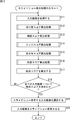
- step S ⁇ b> 11 the acquisition unit 22 acquires one of the input images designated by the user from the recording unit 21 and supplies the input image to the blur score calculation unit 23 to the saturation score calculation unit 27 and the display control unit 29. .
- the acquiring unit 22 selects 1 in the folder designated by the user. Get two input images.
- the slide show display of input images refers to a process of displaying a plurality of input images in order.
- step S ⁇ b> 12 the blur degree score calculation unit 23 performs a blur degree score calculation process, calculates a blur degree score for the input image, and supplies it to the total score calculation unit 28.
- step S ⁇ b> 13 the luminance score calculation unit 24 performs a luminance score calculation process, calculates a luminance score for the input image, and supplies the luminance score to the total score calculation unit 28.
- step S ⁇ b> 14 the edge score calculation unit 25 performs an edge score calculation process, calculates an edge score for the input image, and supplies it to the total score calculation unit 28.
- step S ⁇ b> 15 the color distribution score calculation unit 26 performs a color distribution score calculation process, calculates a color distribution score for the input image, and supplies the color distribution score to the total score calculation unit 28.
- step S 16 the saturation score calculation unit 27 performs a saturation score calculation process, calculates a saturation score for the input image, and supplies it to the total score calculation unit 28.
- step S17 the total score calculation unit 28 calculates a total score for the input image based on the feature-specific scores supplied from the blur score calculation unit 23 to the saturation score calculation unit 27.
- the total score calculation unit 28 converts the feature-specific score into a score determined in advance for the value of the feature-specific score using a conversion table that is stored in advance for each feature-specific score. The total (total) of scores obtained for other scores is taken as the total score.
- the total score calculating unit 28 A blur degree score is obtained from the blur degree score conversion table 13.
- the score of the blur score is 0, and if the blur score is 0.2 or more and less than 0.3, the score of the blur score is 1 and the blur score is 0.3 or more. If it is less than 0.5, the score of the blur degree score is 2.
- the score of the blur score is 3 and if the blur score is 0.7 or more and less than 0.9, the score of the blur score is 5 and the blur score is If it is 0.9 or more, the score of the blur degree score is 10.
- the score determined for each range of the value of the blur degree score is determined based on the blur degree score obtained from the professional image and amateur image prepared in advance.
- a professional image is an image with a high general evaluation (good shooting) taken by a photographic specialist
- an amateur image is a low general evaluation taken by an amateur ( An image that is not well taken.
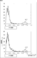
- the blur degree score is obtained for a plurality of professional images and amateur images, and the result shown in FIG. 14 is obtained.
- the vertical axis indicates the number of professional images or amateur images taken as samples, and the horizontal axis indicates the value of the blur degree score.
- the upper side shows the distribution of the blur degree score of the professional image
- the lower side of the figure shows the distribution of the degree of blur score of the amateur image
- the blur score of amateur images is less than 0.4 for most samples, but there are also some with a score of 0.4 or more.
- the amateur image includes some images that are totally blurred.
- the blur degree score of the professional image When comparing the blur degree score of the professional image with the blur degree score of the amateur image, there is no single professional image in the range indicated by the arrow A11 in the distribution of the professional image, that is, the blur degree score is 0.8 or more. On the other hand, there are several amateur images in which the range indicated by the arrow A12 in the distribution of amateur images, that is, the blur score is 0.8 or more.
- the degree of blur score obtained for an input image is 0.8 or more
- the input image is likely to be an amateur image, that is, an image that is not well-captured.
- the total value of the scores for each characteristic score is the total score, and the smaller the total score is, the better the shooting is.
- the score for the degree of blur score is set to a large value so that the total score becomes large.
- the smaller the blur score the smaller the score for the blur score.
- scores for each feature score range are determined by comparing the feature scores of professional images and amateur images prepared in advance, and conversion for each feature score is performed. A table is obtained in advance.
- each feature score has a range of values that can more accurately specify whether the input image is close to a professional image or an amateur image. Therefore, if the score is defined for each characteristic score range, and the scores for each feature score are summed to obtain a total score, it is possible to more appropriately evaluate the shooting condition of the input image. become.
- converting each characteristic score into a score using the conversion table and obtaining a total score by calculating the sum of those scores is to add each characteristic score with a weight to obtain a total score. It corresponds to that.
- the total score calculation unit 28 supplies the obtained total score to the display control unit 29. Then, the process proceeds from step S17 to step S18.
- step S18 the image processing apparatus 11 determines whether or not a total score has been obtained for all input images. For example, when the total score of all the input images designated by the user for slide show display is obtained, it is determined that the total score is obtained for all the input images.
- step S18 If it is determined in step S18 that the total score has not yet been obtained for all input images, the process returns to step S11 and the above-described process is repeated. That is, the acquisition unit 22 acquires the next input image and obtains an overall score for the input image.
- step S19 the display control unit 29 selects the input images to be displayed as a slide show.
- the display control unit 29 displays, based on the total score of each input image supplied from the total score calculation unit 28, the input image supplied from the acquisition unit 22 that has a total score equal to or less than a predetermined threshold. Select as input image. Note that the lower the value of the total score, the higher the evaluation of the shooting degree of the input image.
- an input image whose total score is equal to or less than the threshold value is selected, it is possible to display only an input image having a high evaluation of shooting quality, that is, an input image close to a professional image to some extent.
- a predetermined number of input images to be displayed may be selected in ascending order of the total score.
- step S20 the display control unit 29 causes the input images selected in step S19 to be sequentially supplied to and displayed on the display unit 30, thereby displaying the input images as a slide show.
- the slide show display process ends. In this way, when the selected input images are displayed as a slide show, the user can appreciate only the input images with high evaluation.
- the image processing apparatus 11 obtains a feature-specific score for each input image, and calculates a total score based on the feature-specific score. As described above, by calculating the total score based on a plurality of feature-specific scores, it is possible to more appropriately evaluate the shooting condition of the input image.
- step S51 the edge map generation unit 61 generates an edge map using the input image supplied from the acquisition unit 22.
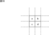
- the edge map generation unit 61 divides the input image into blocks each having a size of 2 ⁇ 2 pixels, and pixel values between the pixels in each block according to the following expressions (1) to (6).
- the absolute value M TL-TR to the absolute value M BL-BR are calculated.
- a, b, c, and d represent pixel values of pixels in a 2 ⁇ 2 pixel size block of the input image.
- the pixel value a indicates the pixel value of the upper left pixel in the figure in the block.
- the pixel value b indicates the pixel value of the upper right pixel in the block
- the pixel value c indicates the pixel value of the lower left pixel in the block
- the pixel value d indicates the right value in the block.
- the pixel value of the lower pixel is shown.
- each of the absolute values M TL-TR to M BL-BR indicates the absolute value of the difference between the pixel values of pixels adjacent in each direction in the block, that is, the edge strength in each direction.
- the edge map generator 61 calculates an average value M Ave of the absolute values M TL-TR to M BL-BR by the following equation (7).
- This average value M Ave indicates the average value of the edge strengths in the vertical, horizontal, and diagonal directions in the block.
- the edge map generation unit 61 generates the edge map of the scale SC1 by arranging the calculated average value M Ave of each block in the same order as the corresponding block of the input image.
- the edge map generation unit 61 generates an averaged image of the scale SC2 and the scale SC3 according to the following equation (8) in order to generate an edge map of the scale SC2 and the scale SC3.
- P i + 1 (x, y) indicates the pixel value of the pixel located at the coordinate (x, y) in the averaged image of the scale SCi + 1. It is assumed that the averaged image of scale SC1 is an input image.
- the averaged image of the scale SC2 is an image in which the average value of the pixel values in each block obtained by dividing the input image into blocks each having a size of 2 ⁇ 2 pixels is used as the pixel value of one pixel.
- the average image of the scale SC3 is obtained by dividing the average image of the scale SC2 into blocks each having a size of 2 ⁇ 2 pixels, and setting the average value of the pixel values in each block as the pixel value of one pixel. It is an image.
- the edge map generation unit 61 performs the same processing as that performed on the input image using the equations (1) to (7) for the averaged images of the scale SC2 and the scale SC3, and the scale SC2 And an edge map of scale SC3.
- the edge maps of the scales SC1 to SC3 are images obtained by extracting edge components of different frequency bands from the input image.
- the number of pixels in the edge map of the scale SC1 is 1/4 (vertical 1/2 ⁇ width 1/2) of the input image
- the number of pixels in the edge map of the scale SC2 is 1/16 (vertical 1/4).
- ⁇ horizontal 1/4 the number of pixels of the edge map of the scale SC3 is 1/64 (vertical 1/8 ⁇ horizontal 1/8) of the input image.
- the edge map generator 61 supplies the generated edge maps of the scales SC1 to SC3 to the dynamic range detector 62 and the local max generator 64.
- edge maps of different scales in units of blocks of different sizes, variation in edge strength can be suppressed.
- step S52 the dynamic range detecting unit 62 detects the dynamic range of the input image using the edge map supplied from the edge map generating unit 61, and supplies the detection result to the calculation parameter adjusting unit 63.
- the dynamic range detection unit 62 detects the maximum value and the minimum value of the pixel values from the edge maps of the scales SC1 to SC3, and obtains a value obtained by subtracting the minimum value from the maximum value of the detected pixel values.
- the dynamic range of the edge strength of the input image is used. That is, the difference between the maximum value and the minimum value of the edge strength of the input image is detected as the dynamic range.
- a dynamic range may be detected for each edge map, and a maximum value or an average value of the detected dynamic range may be adopted as a dynamic range that is actually used.
- step S53 the calculation parameter adjustment unit 63 sets the initial value of the calculation parameter according to the dynamic range supplied from the dynamic range detection unit 62.
- the calculation parameter adjustment unit 63 sets the input image as a low dynamic range image when the dynamic range is less than a predetermined threshold value, and sets the input image as a high dynamic range image when the dynamic range is equal to or greater than the threshold value.
- the calculation parameter adjustment unit 63 sets an initial value for the low dynamic range image as the calculation parameter.
- the calculation parameter adjustment unit 63 sets an initial value for the high dynamic range image as the calculation parameter.
- the initial value of the edge reference value for an image having a low dynamic range is set to a high dynamic range so that a sufficient amount of edge points can be extracted to make the detection accuracy of the degree of blur of the input image equal to or higher than a certain level.
- the value is smaller than the initial value of the image edge reference value.
- the initial value of the extraction reference value for the low dynamic range image is set to a smaller value than the initial value of the extraction reference value for the high dynamic range image.
- the calculation parameter adjustment unit 63 supplies the edge reference value set according to the dynamic range to the edge point extraction unit 65, and supplies the edge reference value and the extraction reference value to the extraction amount determination unit 66.
- step S54 the local max generation unit 64 generates a local max using the edge map supplied from the edge map generation unit 61, and supplies the local max to the edge point extraction unit 65 and the edge analysis unit 67.
- the local max generation unit 64 divides the edge map of the scale SC1 into 2 ⁇ 2 pixel blocks as shown on the left side of FIG. Then, the local max generation unit 64 generates the local max LM1 of the scale SC1 by extracting the maximum value of each block of the edge map and arranging the extracted maximum values in the same order as the corresponding blocks. That is, the maximum pixel value of the pixels in each block is extracted.
- the local max generation unit 64 divides the edge map of the scale SC2 into 4 ⁇ 4 pixel blocks as shown in the center of the drawing. Then, the local max generation unit 64 generates the local max LM2 of the scale SC2 by extracting the maximum value of each block of the edge map and arranging the extracted maximum values in the same order as the corresponding blocks.
- the local max generation unit 64 divides the edge map of the scale SC3 into 8 ⁇ 8 pixel blocks as shown on the right side in the drawing. Then, the local max generation unit 64 generates the local max LM3 of the scale SC3 by extracting the maximum value of each block of the edge map and arranging the extracted maximum values in the same order as the corresponding blocks.
- step S55 the edge point extraction unit 65 extracts an edge point from the input image using the edge reference value from the calculation parameter adjustment unit 63 and the local max supplied from the local max generation unit 64.
- the edge point extraction unit 65 selects one pixel of the input image and sets it as the target pixel. Further, the edge point extraction unit 65 sets the coordinates of the selected pixel of interest on the input image in the xy coordinate system as (x, y), and coordinates of the pixel of the local max LM1 corresponding to the pixel of interest according to the following equation (9). Find (x1, y1).
- the coordinates of the pixel of the local max LM1 corresponding to the target pixel of the input image are the x coordinate and the y coordinate of the target pixel. Each of the values becomes 1/4.
- the edge point extraction unit 65 calculates the coordinates (x2, y2) of the pixel of the local max LM2 corresponding to the target pixel and the local max LM3 corresponding to the target pixel by the following formulas (10) and (11). Pixel coordinates (x3, y3) are obtained.
- the edge point extraction unit 65 extracts the target pixel as an edge point in the local max LM1. Then, the edge point extraction unit 65 stores the pixel value of the coordinate (x, y) of the target pixel and the coordinate (x1, y1) of the local max LM1 in association with each other.
- the edge point extraction unit 65 extracts the target pixel as an edge point in the local max LM2, and
- the pixel values of the coordinates (x, y) and the coordinates (x2, y2) of the local max LM2 are stored in association with each other.
- the edge point extraction unit 65 extracts the target pixel as an edge point in the local max LM3, and (X, y) and the pixel value of the coordinates (x3, y3) of the local max LM3 are stored in association with each other.
- the edge point extraction unit 65 repeats the above processing until all the pixels on the input image are regarded as the target pixel.
- edge points based on the local max LM1, among the 4 ⁇ 4 pixel blocks on the input image, pixels included in a block whose edge strength is equal to or higher than the edge reference value are extracted as edge points.
- pixels included in the block whose edge intensity in the block is equal to or higher than the edge reference value are extracted as edge points.
- pixels included in a block in which the edge strength in the block is equal to or higher than the edge reference value among the 64 ⁇ 64 pixel blocks on the input image are extracted as edge points.
- pixels included in at least one block of 4 ⁇ 4 pixels, 16 ⁇ 16 pixels, or 64 ⁇ 64 pixels of the input image whose edge intensity is equal to or higher than the edge reference value are extracted as edge points.
- the edge point extraction unit 65 is an edge that is a table in which the coordinates (x, y) of the edge point extracted based on the local max LM1 and the pixel values of the pixels of the local max LM1 corresponding to the edge point are associated with each other.
- a point table ET1 is generated.
- the edge point extraction unit 65 associates the edge point coordinates (x, y) extracted based on the local max LM2 with the pixel value of the pixel of the local max LM2 corresponding to the edge point.
- a point table ET2 is generated.
- the edge point extraction unit 65 also associates the edge point coordinates (x, y) extracted based on the local max LM3 with the pixel values of the pixels of the local max LM3 corresponding to the edge point.
- a table ET3 is also generated.
- the edge point extraction unit 65 supplies the generated edge point table to the extraction amount determination unit 66.
- the extraction amount determination unit 66 determines whether the edge point extraction amount is appropriate using the edge point table supplied from the edge point extraction unit 65. For example, the extraction amount determination unit 66 has the total number of extracted edge points, that is, the total number of data in the edge point table ET1 to the edge point table ET3, less than the extraction reference value supplied from the calculation parameter adjustment unit 63. In this case, it is determined that the edge point extraction amount is not appropriate.
- step S56 If it is determined in step S56 that the edge point extraction amount is not appropriate, the extraction amount determination unit 66 notifies the calculation parameter adjustment unit 63 that the edge point extraction amount is not appropriate, and the process proceeds to step S57.
- step S57 the calculation parameter adjustment unit 63 adjusts the calculation parameter in accordance with the notification from the extraction amount determination unit 66.
- the calculation parameter adjustment unit 63 reduces the edge reference value by a predetermined value from the value set at the current time so that more edge points are extracted than the current time.
- the calculation parameter adjustment unit 63 supplies the adjusted edge reference value to the edge point extraction unit 65 and the extraction amount determination unit 66.
- step S55 the process thereafter returns to step S55, and the above-described process is repeated until it is determined that the edge point extraction amount is appropriate.
- step S56 If it is determined in step S56 that the edge point extraction amount is appropriate, the extraction amount determination unit 66 supplies the edge reference value from the calculation parameter adjustment unit 63 and the edge point table to the edge analysis unit 67. Then, the process proceeds to step S58.
- Edge points are also extracted from blocks with weak edge strength.
- edge points are extracted from blocks having as strong edge strength as possible so that edge points constituting stronger edges are extracted.
- step S58 the edge analysis unit 67 performs edge analysis using the edge reference value and edge point table supplied from the extraction amount determination unit 66 and the local max supplied from the local max generation unit 64.
- the edge analysis unit 67 sets one of the edge points extracted from the input image as a target pixel based on the edge point table ET1 to the edge point table ET3. Then, the edge analysis unit 67 sets the coordinates of the target pixel in the xy coordinate system to (x, y), and the pixels of local max LM1 to local max LM3 corresponding to the target pixel according to the above-described equations (9) to (11). The coordinates (x1, y1) to coordinates (x3, y3) are obtained.
- the edge analysis unit 67 is a pixel value of a pixel in a block on the local max LM1 of m ⁇ m pixels (for example, 4 ⁇ 4 pixels) with the pixel at the coordinates (x1, y1) of the local max LM1 as the pixel at the upper left corner.
- the maximum value of is set to LocalxMax1 (x1, y1).
- the edge analysis unit 67 determines the maximum value of the pixel values in a block of n ⁇ n pixels (for example, 2 ⁇ 2 pixels) having the pixel at the coordinates (x2, y2) of the local max LM2 as the upper left corner pixel.
- m ⁇ m used for setting Local ⁇ Max1 (x1, y1) and n ⁇ n parameters used for setting Local Max2 (x2, y2) correspond to one pixel of local max LM1 to local max LM3. This is a parameter for adjusting the difference in the block size of the input image.
- the edge analysis unit 67 determines whether Local Max1 (x1, y1), Local Max2 (x2, y2), and Local Max3 (x3, y3) satisfy the following conditional expression (12). If Local Max1 (x1, y1), Local Max2 (x2, y2), and Local Max3 (x3, y3) satisfy the conditional expression (12), the edge analysis unit 67 increments the value of the variable Nedge by one.
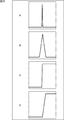
- edge points satisfying the conditional expression (12) are estimated to be edge points that constitute an edge having a certain strength or higher, such as the edges shown in A to D of FIG. Is done.
- the edge shown in A of FIG. 18 is a steep impulse-like edge
- the edge shown in B of FIG. 18 is a pulse-like edge having a gentler slope than the edge of FIG.
- the edge indicated by 18 C is a step-like edge having a substantially vertical inclination.
- the edge shown in D of FIG. 18 is a stepped edge having a gentler slope than the edge of C of FIG.
- the edge analysis unit 67 further satisfies the following conditional expression (13) when Local Max1 (x1, y1), Local Max2 (x2, y2), and Local Max3 (x3, y3) satisfy the conditional expression (12): It is determined whether or not conditional expression (14) is satisfied.
- conditional expression (13) When Local Max1 (x1, y1), Local Max2 (x2, y2), and Local Max3 (x3, y3) satisfy the conditional expression (13) or conditional expression (14), the edge analysis unit 67 determines the value of the variable Nsmallblur Is incremented by one.
- an edge point that satisfies the conditional expression (12) and satisfies the conditional expression (13) or the conditional expression (14) has a certain strength or more, but the edge of A in FIG. 18 or the edge C in FIG. It is presumed that the edge point is an edge point that constitutes an edge having the structure of B of FIG. 18 or D of FIG.
- the edge analysis unit 67 determines that Local ⁇ Max1 (x1, y1), Local Max2 (x2, y2), and Local Max3 (x3, y3) satisfy the conditional expression (12), and the conditional expression (13) or the conditional expression If (14) is satisfied, it is determined whether Local Max1 (x1, y1) satisfies the following conditional expression (15). When Local Max1 (x1, y1) satisfies the conditional expression (15), the edge analysis unit 67 increments the value of the variable Nlargeblur by one.
- an edge point that satisfies conditional expression (12), satisfies conditional expression (13) or conditional expression (14), and satisfies conditional expression (15) is B or B in FIG.
- the edge points constitute the edge where the blur has occurred and the sharpness has been lost. In other words, it is estimated that blur is occurring at the edge point.
- the edge analysis unit 67 repeats the above processing until all edge points extracted from the input image are set as the target pixel. As a result, among the extracted edge points, the number Nedge of edge points, the number Nedgeblur of edge points, and the number Nlargeblur of edge points are obtained.
- the number Nedge is the number of edge points that satisfy the conditional expression (12), and the number Nsmallblur satisfies the conditional expression (12) and also satisfies the conditional expression (13) or the conditional expression (14). Is the number of edge points to be performed.
- the number Nlargeblur is the number of edge points that satisfy the conditional expression (12), the conditional expression (13) or the conditional expression (14), and the conditional expression (15).
- the edge analysis unit 67 supplies the calculated number Nsmallblur and number Nlargeblur to the blur degree detection unit 68.
- step S59 the blur degree detection unit 68 calculates the following equation (16) using the number Nsmallblur and the number Nlargeblur from the edge analysis unit 67, and calculates the blur degree BlurEstimation as an index of the degree of blur of the input image. Find as a score.
- the degree of blur BlurEstimation is estimated to constitute an edge where blur is generated among edge points estimated to constitute an edge having the structure of B in FIG. 18 or D in FIG. This is the ratio of edge points. Therefore, it is estimated that the greater the degree of blur BlurEstimation, the greater the degree of blur in the input image.
- the blur degree detection unit 68 obtains the blur degree score
- the blur degree score is supplied to the total score calculation unit 28, the blur degree score calculation process ends, and the process proceeds to step S13 in FIG. .
- the blur degree score calculation unit 23 calculates the blur degree score indicating the degree of blur of the entire input image from the input image.
- the conditions for extracting edge points and the amount of edge points extracted are appropriately controlled according to the input image, so that the degree of blur of the input image can be detected with higher accuracy.
- the degree of blur of the entire input image is obtained as the blur degree score.
- the degree of blur of the subject part may be obtained as the degree of blur score only for the subject part in the input image.
- step S 81 the subject extraction unit 91 performs subject map generation processing, generates a subject map from the input image supplied from the acquisition unit 22, and supplies the subject map to the multiplication unit 92. Details of the subject map generation process will be described later.
- step S82 the multiplication unit 92 multiplies the input map supplied from the acquisition unit 22 by the subject map supplied from the subject extraction unit 91, generates a subject image, and supplies the subject image to the histogram generation unit 93. That is, assuming that the pixel of interest in the subject image is the pixel of interest, the product of the pixel value of the pixel of the subject map and the pixel value of the pixel of the input image at the same position as the pixel of interest is the pixel value of the pixel of interest.
- This subject image is an image in which only the subject portion of the input image is displayed.
- step S ⁇ b> 83 the histogram generation unit 93 generates a luminance histogram using the range of the luminance value of the pixel of the subject image as a bin based on the subject image supplied from the multiplication unit 92, and supplies it to the normalization unit 94.
- the normalization unit 94 normalizes the histogram from the histogram generation unit 93 and supplies the normalized histogram to the score calculation unit 95.
- step S84 the score calculation unit 95 calculates a luminance score by the K-NN (K-Nearest Neighbor) method or the like based on the histogram supplied from the normalization unit 94 and supplies the luminance score to the total score calculation unit 28.
- K-NN K-Nearest Neighbor
- the score calculation unit 95 holds a plurality of luminance histograms generated by processing similar to the processing in steps S81 to S83 for professional images and amateur images prepared in advance.
- the score calculation unit 95 calculates the distance between the histograms of the plurality of professional images and amateur images stored in advance and the histogram from the normalization unit 94.
- the score calculation unit 95 sets the total value of the difference between the frequency values of each bin between the luminance histogram of the input image and one histogram stored in advance as the distance between the histograms. That is, the frequency value difference between bins having the same representative value is obtained, and the sum of the differences obtained for each bin is used as the distance between the histograms.
- the score calculation unit 95 selects K distances in ascending order of the distance value from the distances between the histogram of the subject image and the histogram stored in advance.
- the score calculation unit 95 subtracts the number of the distance between the histogram of the subject image and the amateur image from the number of the distances between the histogram of the subject image and the professional image among the selected K distances, and obtained as a result.
- the value is the luminance score.
- the distance between the histogram of the subject image and the histogram of the professional image or amateur image is the sum of the differences between the frequency values of each bin, the closer the luminance distribution between these images is, the closer the distance is. The value becomes smaller. That is, the smaller the distance, the closer the subject image is to the professional image or amateur image that is the processing target.
- the luminance score indicates the degree of similarity of the luminance distribution with respect to the professional image of the subject image, and an input image with a larger luminance score value is an image with a higher evaluation of the degree of shooting.
- the score calculation unit 95 supplies the calculated luminance score to the total score calculation unit 28, and the luminance score calculation process ends. Then, the process proceeds to step S14 in FIG.
- the luminance score calculation unit 24 extracts the subject area from the input image, and the luminance distribution in the subject area and the luminance distribution in the subject area of the professional image and amateur image prepared in advance. Are compared to calculate a luminance score. In this way, by comparing the luminance distributions for only the subject area of the input image and calculating the luminance score, it is possible to more appropriately evaluate the shooting condition of the input image.
- an image in which the luminance of the subject portion in the image is bright is regarded as a highly evaluated image that can be taken well even if the background portion is dark.
- the luminance distribution of the subject portion is close to the luminance distribution of the subject portion of the professional image, but the background portion. If the luminance distributions of the images are different, the evaluation of the image becomes low.
- the luminance distribution of the subject area in the image is important, and the luminance distribution of the background portion is not necessarily required for the evaluation. In other words, it is possible to evaluate the input image sufficiently from the luminance distribution of the subject part. Considering the luminance distribution of the background part, on the contrary, the evaluation method becomes complicated or erroneous evaluation is performed. There is also a fear.
- the luminance score calculation unit 24 calculates the luminance score for only the subject area of the input image as a processing target, so that it is possible to more easily and more appropriately evaluate the shooting condition of the input image.
- step S11 the luminance information extraction unit 121 performs luminance information extraction processing, generates a luminance information map based on the input image supplied from the acquisition unit 22, and supplies the luminance information map to the subject map generation unit 125.
- step S ⁇ b> 112 the color information extraction unit 122 performs color information extraction processing, generates a color information map based on the input image supplied from the acquisition unit 22, and supplies the color information map to the subject map generation unit 125.
- step S113 the edge information extraction unit 123 performs edge information extraction processing, generates an edge information map based on the input image supplied from the acquisition unit 22, and supplies it to the subject map generation unit 125.
- step S ⁇ b> 114 the face information extraction unit 124 performs face information extraction processing, generates a face information map based on the input image supplied from the acquisition unit 22, and supplies the face information map to the subject map generation unit 125.
- luminance information extraction processing color information extraction processing, edge information extraction processing, and face information extraction processing will be described later.
- step S115 the subject map generation unit 125 generates a subject map using the luminance information map or the face information map supplied from the luminance information extraction unit 121 to the face information extraction unit 124, and sends it to the multiplication unit 92 in FIG. Supply.
- the subject map generation unit 125 linearly combines each information map using the information weight Wb, which is a weight obtained in advance for each information map, and further, the pixel value of the map obtained as a result thereof is previously stored.
- the subject weight Wc which is the obtained weight, is multiplied and normalized to obtain a subject map.
- the pixel value of each information map at the same position as the pixel of interest is multiplied by the information weight Wb for each information map, and the information weight Wb Is the pixel value of the target pixel. Further, the pixel value of each pixel of the subject map obtained in this way is multiplied by a subject weight Wc obtained in advance for the subject map to be normalized to obtain a final subject map.
- an RG difference color information map and a BY difference color information map are used as the color information map, and 0 degree, 45 degree, 90 degree, and 135 degree are used as the edge information map.
- the subject information map is generated using the edge information maps in the respective directions.
- the subject weight Wc is obtained in advance by learning, and normalization is performed so that the pixel value of each pixel of the subject map becomes either 0 or 1. That is, in normalization, the pixel value of each pixel is binarized by threshold processing using a predetermined threshold.
- the subject extraction unit 91 extracts each piece of information from the area of the input image and generates a subject map.
- the luminance image generation unit 151 generates a luminance image using the input image supplied from the acquisition unit 22, and supplies the luminance image to the pyramid image generation unit 152.
- the luminance image generation unit 151 multiplies the value of each component of R, G, and B of the pixel of the input image by a coefficient predetermined for each component, and sums the value of each component multiplied by the coefficient Is the pixel value of the pixel of the luminance image at the same position as the pixel of the input image. That is, the luminance component of the component signal composed of the luminance component (Y) and the color difference components (Cb, Cr) is obtained.
- the average value of the R, G, and B component values of the pixel may be the pixel value of the pixel of the luminance image.
- step S152 the pyramid image generation unit 152 generates pyramid images of the respective levels L1 to L8 based on the luminance image supplied from the luminance image generation unit 151, and supplies the pyramid image to the difference calculation unit 153.
- step S153 the difference calculation unit 153 generates and normalizes the difference image using the pyramid image supplied from the pyramid image generation unit 152, and supplies the difference image to the luminance information map generation unit 154.
- the normalization is performed so that the pixel value of the pixel of the difference image becomes a value between 0 and 255, for example.
- the difference calculation unit 153 includes the level L6 and the level L3, the level L7 and the level L3, the level L7 and the level L4, the level L8 and the level L4, and the level L8 and the level among the luminance pyramid images of each layer.
- the difference of the pyramid image of the combination of each layer of L5 is obtained.
- a total of five luminance difference images are obtained.
- the pyramid image of level L6 is up-converted according to the size of the pyramid image of level L3. That is, the pixel value of one pixel of the pyramid image of level L6 before up-conversion is the pixel value of several pixels adjacent to each other of the pyramid image of level L6 after up-conversion corresponding to that pixel. Then, the difference between the pixel value of the pixel of the level L6 pyramid image and the pixel value of the pixel of the level L3 pyramid image at the same position as the pixel is obtained, and the difference is set as the pixel value of the pixel of the difference image.
- the process of generating these difference images is equivalent to performing a filter process using a bandpass filter on the luminance image and extracting a predetermined frequency component from the luminance image.
- the pixel value of the pixel of the difference image obtained in this way is the difference between the luminance values of the pyramid images at each level, that is, the difference between the luminance at a predetermined pixel in the input image and the average luminance around the pixel. Is shown.
- an area having a large luminance difference from the surroundings in an image is an area that catches the eye of a person who sees the image, so that the area is likely to be a subject area. Therefore, it can be said that in each difference image, a pixel having a larger pixel value is a region that is more likely to be a subject region.
- step S154 the luminance information map generation unit 154 generates a luminance information map based on the difference image supplied from the difference calculation unit 153 and supplies the luminance information map to the subject map generation unit 125.
- the luminance information map is supplied from the luminance information map generation unit 154 to the subject map generation unit 125, the luminance information extraction process ends, and the process proceeds to step S112 in FIG.
- the luminance information map generation unit 154 weights the supplied five difference images with a difference weight Wa that is a weight for each difference image obtained in advance to obtain one image. That is, the pixel values of the pixels at the same position in each difference image are multiplied by the difference weight Wa to obtain the sum of the pixel values multiplied by the difference weight Wa.
- the difference images are up-converted so that the difference images have the same size.
- the luminance information extraction unit 121 obtains a luminance image from the input image and generates a luminance information map from the luminance image.
- the difference between the luminance of each area of the input image and the average luminance of the surrounding area is extracted as a feature amount, and a luminance information map indicating the feature amount is generated.
- the luminance information map thus obtained, it is possible to easily detect a region having a large difference in luminance, that is, a region that is easily noticeable by an observer who looks at the input image.
- step S181 the RG difference image generation unit 181 generates an RG difference image using the input image supplied from the acquisition unit 22, and supplies the RG difference image to the pyramid image generation unit 183.
- step S182 the BY difference image generation unit 182 generates a BY difference image using the input image supplied from the acquisition unit 22, and supplies the BY difference image to the pyramid image generation unit 184.
- step S183 the pyramid image generation unit 183 and the pyramid image generation unit 184 generate a pyramid image using the RG difference image from the RG difference image generation unit 181 and the BY difference image from the BY difference image generation unit 182. .
- the pyramid image generation unit 183 generates a plurality of RG difference images having different resolutions, thereby generating pyramid images of the respective levels L1 to L8 and supplies the pyramid images to the difference calculation unit 185.
- the pyramid image generation unit 184 generates a plurality of BY difference images having different resolutions, thereby generating pyramid images of the respective levels L1 to L8 and supplies the pyramid images to the difference calculation unit 186.
- step S184 the difference calculation unit 185 and the difference calculation unit 186 generate and normalize the difference image based on the pyramid images supplied from the pyramid image generation unit 183 and the pyramid image generation unit 184, and the color information map generation unit 187. And supplied to the color information map generation unit 188.
- the pixel value of the pixel is set to a value between 0 and 255.
- the difference calculation unit 185 includes the level L6 and the level L3, the level L7 and the level L3, the level L7 and the level L4, the level L8 and the level L4, and the level L8 and the level L5 among the RG difference pyramid images of each layer.
- the difference of the pyramid image of each layer combination is obtained.
- a difference image of a total of five RG differences is obtained.
- the difference calculation unit 186 includes a level L6 and a level L3, a level L7 and a level L3, a level L7 and a level L4, a level L8 and a level L4, and a level L8 and a level among the BY difference pyramid images of each layer.
- the difference of the pyramid image of the combination of each layer of L5 is obtained.
- a difference image of a total of five BY differences is obtained.
- the process of generating these difference images is equivalent to performing a filtering process using a bandpass filter on the RG difference image or the BY difference image and extracting a predetermined frequency component from the RG difference image or the BY difference image.
- the pixel value of the pixel of the difference image obtained in this way is the difference between the specific color component of the pyramid image at each level, that is, the specific color component in the pixel of the input image and the average around the pixel. A difference from a specific color component is shown.
- an area of a color that stands out from the surroundings in the image that is, an area that has a large difference from the surroundings of a specific color component is an eye-catching area of the person who sees the image. Is likely. Therefore, it can be said that in each difference image, a pixel having a larger pixel value is a region that is more likely to be a subject region.
- step S185 the color information map generation unit 187 and the color information map generation unit 188 generate a color information map using the difference images from the difference calculation unit 185 and the difference calculation unit 186, and supply the color information map to the subject map generation unit 125. .
- the color information map generation unit 187 weights and adds the difference image of the RG difference supplied from the difference calculation unit 185 with the difference weight Wa for each difference image obtained in advance. Let it be a color information map.
- the color information map generation unit 188 weights and adds the difference image of the BY difference supplied from the difference calculation unit 186 with the difference weight Wa obtained in advance, and the color information map of one BY difference And Note that when the color information map is generated, the difference images are up-converted so that the difference images have the same size.
- the color information extraction unit 122 obtains an image of a difference between specific color components from the input image, and generates a color information map from the image. That is, the color information extraction unit 122 extracts a difference between a specific color component in each area of the input image and an average specific color component in an area around the area as a feature quantity, and the feature quantity is extracted. A color information map is generated. According to the color information map obtained in this way, it is possible to easily detect a region where a difference between specific color components is large in the input image, that is, a region that is easily noticeable by an observer who looks at the input image. .
- the color difference component Cr and the color difference component Cb may be extracted.
- the color difference component Cr is a difference between the R component and the luminance component
- the color difference component Cb is a difference between the B component and the luminance component.
- FIG. 23 is a flowchart for explaining edge information extraction processing corresponding to the processing in step S113 in FIG. Hereinafter, the edge information extraction process will be described.
- step S ⁇ b> 211 the edge image generation unit 211 to the edge image generation unit 214 perform a filtering process using a Gabor filter on the input image supplied from the acquisition unit 22 to 0 degree, 45 degrees, 90 degrees, and 135. An edge image having the edge intensity in the direction of degrees as the pixel value of the pixel is generated. Then, the edge image generation unit 211 to the edge image generation unit 214 supply the generated edge image to the pyramid image generation unit 215 to the pyramid image generation unit 218.
- step S212 the pyramid image generation unit 215 through the pyramid image generation unit 218 generate pyramid images using the edge images from the edge image generation unit 211 through the edge image generation unit 214, and the difference calculation unit 219 through the difference calculation unit. 222 is supplied.
- the pyramid image generation unit 215 generates a plurality of 0 degree direction edge images having different resolutions, thereby generating pyramid images of the respective layers of the levels L1 to L8 and supplies them to the difference calculation unit 219.
- the pyramid image generation unit 216 through the pyramid image generation unit 218 generate pyramid images of the levels L1 through L8 and supply them to the difference calculation unit 220 through the difference calculation unit 222.
- step S213 the difference calculation unit 219 to the difference calculation unit 222 generate and normalize the difference image using the pyramid images from the pyramid image generation unit 215 to the pyramid image generation unit 218, and the edge information map generation unit 223 to the edge This is supplied to the information map generator 226.
- the pixel value of the pixel is set to a value between 0 and 255.
- the difference calculation unit 219 includes the level L6 and the level L3, the level L7 and the level L3, the level L7 and the level L4, among the pyramid images of the edge in the 0 degree direction of each layer supplied from the pyramid image generation unit 215.
- the difference of the pyramid image of the combination of level L8 and level L4, and level L8 and level L5 is calculated
- the difference calculation unit 220 to the difference calculation unit 222 include the level L6 and level L3, the level L7 and level L3, the level L7 and level L4, the level L8 and level L4, and the level L8 and The difference of the pyramid image of the combination of each layer of level L5 is obtained. As a result, a total of five difference images are obtained for the edges in each direction.
- the process of generating these difference images is equivalent to performing a filter process using a bandpass filter on the edge image and extracting a predetermined frequency component from the edge image.
- the pixel values of the pixels of the difference image obtained in this way are the difference in edge strength between the pyramid images at each level, that is, the edge strength at a predetermined position of the input image and the average edge strength around that position. The difference is shown.
- an area having a higher edge strength than the surrounding area in an image is an area that catches the eye of a person who views the image, and therefore, the area is highly likely to be an object area. Therefore, it can be said that in each difference image, a pixel having a larger pixel value is a region that is more likely to be a subject region.
- step S214 the edge information map generation unit 223 through the edge information map generation unit 226 generate edge information maps in the respective directions using the difference images from the difference calculation units 219 through 222, and the subject map generation unit 125. To supply.
- the edge information map generation unit 223 weights and adds the difference image supplied from the difference calculation unit 219 with a previously obtained difference weight Wa to obtain an edge information map in the 0 degree direction.
- the edge information map generation unit 224 to the edge information map generation unit 226 add the difference images from the difference calculation unit 220 to the difference calculation unit 222 with weighting by the difference weight Wa to obtain 45 degrees, 90 degrees, and 135 degrees. Generate an edge information map for each direction in degrees. Note that when the edge information map is generated, the difference image is up-converted so that each difference image has the same size.
- edge information map generation unit 223 through the edge information map generation unit 226 supply a total of four edge information maps in the respective directions thus obtained to the subject map generation unit 125, the edge information extraction processing ends and the processing is completed. Advances to step S114 in FIG.
- the edge information extraction unit 123 obtains a difference image of an edge in a specific direction from the input image, and generates an edge information map from the difference image. That is, the edge information extraction unit 123 extracts the difference between the edge strength in a specific direction in each region of the input image and the average edge strength in a specific direction in the surrounding region of the input image as a feature amount, An edge information map indicating the quantity is generated. According to the edge information map for each direction obtained in this way, in the input image, compared to the surrounding area, a region having a large edge strength in a specific direction, that is, the eyes of the observer who glanced at the input image. An easily attached region can be easily detected.
- a Gabor filter is used for edge extraction.
- an edge extraction filter such as a Sobel filter or a Roberts filter may be used.
- the face detection unit 251 detects a human face region from the input image supplied from the acquisition unit 22, and supplies the detection result to the face information map generation unit 252.
- the face detection unit 251 performs a filtering process using a Gabor filter on the input image, and extracts characteristic regions such as human eyes, mouth, and nose from the input image, whereby a face region in the input image is obtained. Is detected.
- step S242 the face information map generation unit 252 generates a face information map using the detection result from the face detection unit 251, and supplies the face information map to the subject map generation unit 125.
- candidate areas a plurality of rectangular areas (hereinafter referred to as candidate areas) on the input image that are estimated to include a face are detected as face detection results from the input image.
- candidate areas a plurality of candidate areas are detected near a predetermined position on the input image, and some of these candidate areas may overlap each other. That is, for example, when a plurality of areas including the face are obtained as candidate areas for one face area on the input image, some of these candidate areas overlap each other.
- the face information map generation unit 252 generates a detection image having the same size as the input image for each candidate region, with respect to the candidate region obtained by face detection.
- the pixel value of a pixel in the same region as the candidate region to be processed on the detected image is set to a value larger than the pixel value of a pixel in a region different from the candidate region.
- the pixel value of the pixel on the detected image increases as the pixel is located at the same position as the pixel in the candidate area where it is estimated that the human face is more likely to be included.
- the face information map generation unit 252 adds the detected images obtained in this way, generates one image, normalizes it, and sets it as a face information map. Therefore, on the face information map, the pixel value of the pixel in the same region as the region where a part of the plurality of candidate regions on the input image overlaps increases, and the possibility that a face is included is higher. Note that the normalization is performed so that the pixel value of the face information map pixel is a value between 0 and 255, for example.
- the face information extraction unit 124 detects a face from the input image, and generates a face information map from the detection result. According to the face information map obtained in this way, it is possible to easily detect a human face area as a subject in an input image.
- each information map is generated as described above, and a subject map is generated from these information maps.
- edge score calculation process the color distribution score calculation process, and the saturation score calculation process corresponding to the processes in steps S14 to S16 in FIG. 12 will be described with reference to FIGS.
- edge score calculation process corresponding to the process of step S14 of FIG. 12 will be described with reference to the flowchart of FIG. This processing is performed by the edge score calculation unit 25 in FIG.
- step S271 the subject extraction unit 281 performs subject map generation processing, generates a subject map from the input image supplied from the acquisition unit 22, and supplies the subject map to the inversion unit 282.
- the subject map generation process is the same as the subject map generation process described with reference to FIG.
- step S272 the reversing unit 282 performs reversal processing on the subject map supplied from the subject extracting unit 281 and supplies the subject map to the multiplying unit 285. That is, the pixel value of each pixel of the subject map is inverted from 1 to 0 or from 0 to 1. As a result, the background portion in the input image can be extracted by using the inverted subject map.
- step S273 the filter processing unit 283 performs a filter process using a Laplacian filter on the input image supplied from the acquisition unit 22, generates a Laplacian image, and supplies the generated Laplacian image to the normalization unit 284. Further, the normalization unit 284 normalizes the Laplacian image from the filter processing unit 283 and supplies the normalized Laplacian image to the multiplication unit 285.
- step S274 the multiplication unit 285 generates a background image by multiplying the Laplacian image from the normalization unit 284 by the inverted subject map from the inversion unit 282, and supplies the background image to the histogram generation unit 286. That is, the product of the pixel value of the pixel of the Laplacian image and the subject map at the same position is obtained, and the product is used as the pixel value of the pixel of the background image.
- the background image obtained in this way is an image indicating the edge strength of a portion that is not a subject area in the input image, that is, the background portion.
- step S275 the histogram generation unit 286 uses the background image supplied from the multiplication unit 285 to generate a histogram indicating the complexity of the edge in the background portion of the input image.
- the histogram generation unit 286 performs threshold processing on the background image. Specifically, among the pixels of the background image, the pixel value of the pixel value equal to or greater than the threshold value is set as it is, and the pixel value of the pixel value less than the threshold value is set to 0.
- the histogram generation unit 286 generates an edge histogram for the background image subjected to the threshold processing, with the range of pixel values of the background image pixels, that is, the edge intensity value range as a bin. Then, the histogram generation unit 286 supplies the generated edge histogram to the score calculation unit 287.
- step S276 the score calculation unit 287 calculates an edge score using the histogram supplied from the histogram generation unit 286, and supplies the edge score to the total score calculation unit 28.
- the score calculation unit 287 has a frequency value of a bin having the highest frequency value among one or a plurality of bins included in a range of pixel values (edge strength) “0” to “0.1” in the histogram. Are extracted as the maximum frequency value Ma.
- the bin having the largest frequency value is selected from the bins having a representative value between 0 and 0.1, and the frequency value of the bin is set as the maximum frequency value Ma.
- the score calculation unit 287 has a frequency of the bin having the lowest frequency value among one or a plurality of bins included in the pixel value (edge strength) “0.8” to “0.9” in the histogram.
- the value is extracted as the minimum frequency value Mb.
- the bin having the smallest frequency value is selected from bins having a bin representative value between 0.8 and 0.9, and the frequency value of the bin is set as the minimum frequency value Mb.
- the score calculation unit 287 subtracts the minimum frequency value Mb from the maximum frequency value Ma, and sets the value obtained as a result as an edge score.
- the edge score thus obtained indicates the difference between the number of pixels with low edge strength and the number of pixels with high edge strength in the background portion of the input image, that is, the complexity of the edge in the background portion.
- the edge of the background portion is complicated, the maximum frequency value Ma is large, and the minimum frequency value Mb is often small. That is, the edge score of an image close to an amateur image is likely to be a large value.
- the edge of the background portion is simple, that is, there are few pixels with high edge strength, and the maximum frequency value Ma and the minimum frequency value Mb are often small. That is, the edge score of an image close to a professional image is likely to be a small value. Therefore, the edge score indicates that the smaller the value is, the higher the evaluation of how the input image is captured.
- the edge score calculation unit 25 extracts the background portion from the input image, and calculates an edge score indicating the complexity of the edge strength of the background portion based on the edge strength of the background portion. In this way, by calculating the edge score with only the background portion as the processing target, it becomes possible to more appropriately evaluate the shooting condition of the input image.
- the edge of the background portion tends to be complicated in the amateur image, and the edge of the background portion tends to be simple in the professional image. Therefore, by using such a tendency and obtaining an edge score indicating the complexity of the edge only in the background part, it is easier and more appropriate to capture the input image regardless of whether the edge in the subject part is complicated or not. Can be evaluated.
- step S ⁇ b> 301 the R component histogram generation unit 311 to the B component histogram generation unit 313 perform histograms of R (red), G (green), and B (blue) components from the input image supplied from the acquisition unit 22. Is supplied to the normalization unit 314 to the normalization unit 316. For example, as the R component histogram, a histogram in which the range of the R component value of the input image is binned is generated.
- the normalization unit 314 to normalization unit 316 normalize the histogram for each component from the R component histogram generation unit 311 to the B component histogram generation unit 313, and supply the normalized histogram to the histogram generation unit 317.
- step S302 the histogram generation unit 317 generates a color histogram including R, G, and B components using the histogram for each color component supplied from the normalization unit 314 to the normalization unit 316, and scores It supplies to the calculation part 318.
- step S303 the score calculation unit 318 calculates a color distribution score by the K-NN method based on the histogram supplied from the histogram generation unit 317 and supplies the color distribution score to the total score calculation unit 28.
- the score calculation unit 318 holds a plurality of color histograms generated by processing similar to the processing in step S301 and step S302 for professional images and amateur images prepared in advance.
- the score calculation unit 318 calculates the distances between the histograms of the plurality of professional images and amateur images stored in advance and the histogram from the histogram generation unit 317.
- the distance between the histograms is the total value of the difference between the frequency values of each bin between the color histogram of the input image and one histogram stored in advance.
- the score calculation unit 318 selects K distances from the plurality of obtained distances in ascending order of the distance values, and among the selected distances, the score calculation unit 318 determines the number of distances between the input image and the pro image histogram. Subtract the number of histogram distances between the input image and the amateur image. Then, the score calculation unit 318 sets a value obtained as a result of the subtraction as a color distribution score.
- the color distribution score obtained in this way becomes larger as there are more professional images having a color distribution similar to the input image, as in the above-described luminance score. That is, the color distribution score indicates the degree of similarity of the color distribution with respect to the professional image of the input image, and an input image with a larger value of the color distribution score is an image with a higher evaluation of the degree of shooting.
- the score calculation unit 318 supplies the calculated color distribution score to the total score calculation unit 28, and the color distribution score calculation process ends. Then, the process proceeds to step S16 in FIG.
- the color distribution score calculation unit 26 compares the color distribution in the input image with the color distributions of the professional image and amateur image prepared in advance, and calculates the color distribution score. In this way, by comparing the color distribution of the entire input image and calculating the color distribution score, it is possible to more appropriately evaluate the shooting condition of the input image.
- step S331 the conversion unit 341 converts the input image supplied from the acquisition unit 22 into an input image including values of H (hue), S (saturation), and V (lightness) components, and generates a histogram. To the unit 342.
- the histogram generation unit 342 generates a saturation component histogram using the input image supplied from the conversion unit 341, and supplies the generated histogram to the score calculation unit 343.
- the histogram generation unit 342 extracts and extracts pixels having an H (hue) component that is equal to or greater than a predetermined threshold th1 and a V (lightness) component that is equal to or greater than the predetermined threshold th2 from the pixels of the input image.
- a histogram is generated with the range of S (saturation) component values of the pixels as bins.
- step S333 the score calculation unit 343 calculates a saturation score using the saturation histogram supplied from the histogram generation unit 342, and supplies the saturation score to the total score calculation unit 28.
- the score calculation unit 343 approximates the saturation histogram by GMM (Gaussian Mixture Model), and obtains the importance, average value, and variance of each distribution for one or a plurality of distributions.
- the distribution here means a portion having one peak in the entire distribution curve obtained by approximation.
- the score calculation unit 343 sets the variance and average value of the distribution with the highest importance among the distributions as the saturation score. Therefore, in the process of step S17 of FIG. 12, each of the variance and average value of the saturation as the saturation score is converted into a score by the conversion table.
- the saturation score obtained in this way indicates the average value and variance of the saturation components of the entire input image, and the average value and variance value indicate whether the input image is closer to the professional image, Or it can identify whether it is closer to an amateur image. Therefore, it is possible to evaluate the degree of shooting of the input image based on the saturation score.
- the score calculation unit 343 supplies the calculated saturation score to the total score calculation unit 28, and the saturation score calculation process ends. Then, the process proceeds to step S17 in FIG.
- the saturation score calculation unit 27 calculates the average value and variance of the saturation in the input image as the saturation score. In this way, by obtaining the average value and variance of the saturation for the entire input image and using it as the saturation score, it is possible to more appropriately evaluate the shooting condition of the input image.
- the input image can be more appropriately It will be possible to evaluate the shooting conditions.
- the series of processes described above can be executed by hardware or software.
- a program constituting the software may execute various functions by installing a computer incorporated in dedicated hardware or various programs. For example, it is installed from a program recording medium in a general-purpose personal computer or the like.
- FIG. 28 is a block diagram showing an example of the hardware configuration of a computer that executes the above-described series of processing by a program.
- a CPU Central Processing Unit
- ROM Read Only Memory
- RAM Random Access Memory
- An input / output interface 605 is further connected to the bus 604.
- the input / output interface 605 includes an input unit 606 including a keyboard, a mouse, and a microphone, an output unit 607 including a display and a speaker, a recording unit 608 including a hard disk and a non-volatile memory, and a communication unit 609 including a network interface.
- a drive 610 for driving a removable medium 611 such as a magnetic disk, an optical disk, a magneto-optical disk, or a semiconductor memory is connected.
- the CPU 601 loads the program recorded in the recording unit 608 to the RAM 603 via the input / output interface 605 and the bus 604 and executes the program, for example. Is performed.
- the program executed by the computer (CPU 601) is, for example, a magnetic disk (including a flexible disk), an optical disk (CD-ROM (Compact Disc-Read Only Memory), DVD (Digital Versatile Disc), etc.), a magneto-optical disc, or a semiconductor
- the program is recorded on a removable medium 611 that is a package medium including a memory or the like, or is provided via a wired or wireless transmission medium such as a local area network, the Internet, or digital satellite broadcasting.
- the program can be installed in the recording unit 608 via the input / output interface 605 by attaching the removable medium 611 to the drive 610. Further, the program can be received by the communication unit 609 via a wired or wireless transmission medium and installed in the recording unit 608. In addition, the program can be installed in the ROM 602 or the recording unit 608 in advance.
- the program executed by the computer may be a program that is processed in time series in the order described in this specification, or in parallel or at a necessary timing such as when a call is made. It may be a program for processing.
Landscapes
- Engineering & Computer Science (AREA)
- Multimedia (AREA)
- Signal Processing (AREA)
- General Physics & Mathematics (AREA)
- Biomedical Technology (AREA)
- General Health & Medical Sciences (AREA)
- Computer Vision & Pattern Recognition (AREA)
- Physics & Mathematics (AREA)
- Health & Medical Sciences (AREA)
- Theoretical Computer Science (AREA)
- Quality & Reliability (AREA)
- Image Analysis (AREA)
- Studio Devices (AREA)
- Image Processing (AREA)
- Testing, Inspecting, Measuring Of Stereoscopic Televisions And Televisions (AREA)
Abstract
Description
図1は、本発明を適用した画像処理装置の一実施の形態の構成例を示す図である。
また、図1のぼけ度スコア算出部23は、より詳細には、図2に示すように構成される。
また、図1の輝度スコア算出部24は、より詳細には図3に示すように構成される。
ここで、図3の被写体抽出部91は、より詳細には図4に示すように構成される。
次に、図5乃至図8を参照して、図4の輝度情報抽出部121乃至顔情報抽出部124のより詳細な構成について説明する。
図6は、図4の色情報抽出部122のより詳細な構成例を示す図である。
図7は、図4のエッジ情報抽出部123のより詳細な構成例を示す図である。
図8は、図4の顔情報抽出部124のより詳細な構成例を示す図である。
さらに、図1のエッジスコア算出部25は、より詳細には図9に示すように構成される。
また、図1の色分布スコア算出部26は、より詳細には図10に示すように構成される。
さらに、図1の彩度スコア算出部27は、より詳細には図11に示すように構成される。
ところで、ユーザが図1の画像処理装置11を操作し、記録部21に記録されている複数の入力画像を指定して、それらの入力画像のスライドショー表示を指示すると、画像処理装置11は、ユーザの指示に応じてスライドショー表示処理を開始する。
次に、図15のフローチャートを参照して、図12のステップS12の処理に対応するぼけ度スコア算出処理について説明する。
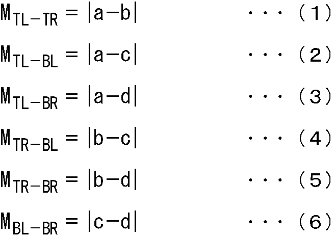





次に、図19のフローチャートを参照して、図12のステップS13の処理に対応する輝度スコア算出処理について説明する。
さらに、図20のフローチャートを参照して、図19のステップS81の処理に対応する被写体マップ生成処理について説明する。
次に、図21乃至図24のフローチャートを参照して、図20のステップS111乃至ステップS114の処理のそれぞれに対応する処理について説明する。
次に、図22のフローチャートを参照して、図20のステップS112の処理に対応する色情報抽出処理について説明する。
図23は、図20のステップS113の処理に対応するエッジ情報抽出処理を説明するフローチャートである。以下、このエッジ情報抽出処理について説明する。
次に、図24のフローチャートを参照して、図20のステップS114の処理に対応する顔情報抽出処理について説明する。
また、以下、図25乃至図27を参照して、図12のステップS14乃至ステップS16の処理に対応する、エッジスコア算出処理、色分布スコア算出処理、および彩度スコア算出処理について説明する。
次に、図26のフローチャートを参照して、図12のステップS15の処理に対応する色分布スコア算出処理について説明する。
次に、図27のフローチャートを参照して、図12のステップS16の処理に対応する彩度スコア算出処理について説明する。
Claims (9)
- 入力画像の全体から第1の特徴の特徴量を抽出し、前記第1の特徴の特徴量に基づいて、前記第1の特徴に基づく前記入力画像に対する評価を示す第1の部分評価値を算出する第1の評価値算出手段と、
前記入力画像の所定の領域から第2の特徴の特徴量を抽出し、前記第2の特徴の特徴量に基づいて、前記第2の特徴に基づく前記入力画像に対する評価を示す第2の部分評価値を算出する第2の評価値算出手段と、
前記第1の部分評価値および前記第2の部分評価値に基づいて、前記入力画像の撮れ具合の評価を示す総合評価値を算出する総合評価値算出手段と
を備える画像処理装置。 - 前記第2の部分評価値算出手段は、
前記入力画像上の被写体の領域が有する第3の特徴の特徴量を、前記入力画像の各領域から抽出することで前記入力画像上の前記被写体の領域を特定する被写体領域特定手段と、
前記入力画像上の前記被写体の含まれる被写体領域、または前記入力画像上の前記被写体の含まれない背景領域の何れかの領域から、前記第2の特徴の特徴量を抽出して、前記第2の部分評価値を算出する算出手段と
を備える請求項1に記載の画像処理装置。 - 前記算出手段は、前記第2の特徴の特徴量として、前記入力画像上の前記被写体領域内の各領域における輝度値を抽出し、前記被写体領域における前記輝度値の分布に基づく前記第2の部分評価値を算出する
請求項2に記載の画像処理装置。 - 前記算出手段は、前記第2の特徴の特徴量として、前記入力画像上の前記背景領域内の各領域におけるエッジ強度を抽出し、前記背景領域における前記エッジの複雑さに基づく前記第2の部分評価値を算出する
請求項2に記載の画像処理装置。 - 前記第1の評価値算出手段は、前記入力画像の全体における、ぼけの度合い、色の分布、彩度の平均、または彩度の分散の少なくとも何れかに基づく前記第1の部分評価値を算出する
請求項1に記載の画像処理装置。 - 前記総合評価値算出手段は、前記第1の部分評価値の値に対して予め定められた値と、前記第2の部分評価値の値に対して予め定められた値とを加算することにより、前記総合評価値を算出する
請求項1に記載の画像処理装置。 - 前記第1の部分評価値の値に対して予め定められた値は、予め得られている、撮れ具合の評価の異なる複数の画像の前記第1の部分評価値に基づいて定められ、
前記第2の部分評価値の値に対して予め定められた値は、予め得られている、撮れ具合の評価の異なる複数の画像の前記第2の部分評価値に基づいて定められる
請求項6に記載の画像処理装置。 - 入力画像の全体から第1の特徴の特徴量を抽出し、前記第1の特徴の特徴量に基づいて、前記第1の特徴に基づく前記入力画像に対する評価を示す第1の部分評価値を算出する第1の評価値算出手段と、
前記入力画像の所定の領域から第2の特徴の特徴量を抽出し、前記第2の特徴の特徴量に基づいて、前記第2の特徴に基づく前記入力画像に対する評価を示す第2の部分評価値を算出する第2の評価値算出手段と、
前記第1の部分評価値および前記第2の部分評価値に基づいて、前記入力画像の撮れ具合の評価を示す総合評価値を算出する総合評価値算出手段と
を備える画像処理装置の画像処理方法であって、
前記第1の評価値算出手段が前記入力画像に基づいて前記第1の部分評価値を算出し、
前記第2の評価値算出手段が前記入力画像に基づいて前記第2の部分評価値を算出し、
前記総合評価値算出手段が、前記第1の部分評価値および前記第2の部分評価値に基づいて前記総合評価値を算出する
ステップを含む画像処理方法。 - 入力画像の全体から第1の特徴の特徴量を抽出し、前記第1の特徴の特徴量に基づいて、前記第1の特徴に基づく前記入力画像に対する評価を示す第1の部分評価値を算出し、
前記入力画像の所定の領域から第2の特徴の特徴量を抽出し、前記第2の特徴の特徴量に基づいて、前記第2の特徴に基づく前記入力画像に対する評価を示す第2の部分評価値を算出し、
前記第1の部分評価値および前記第2の部分評価値に基づいて、前記入力画像の撮れ具合の評価を示す総合評価値を算出する
ステップを含む処理をコンピュータに実行させるプログラム。
Priority Applications (5)
| Application Number | Priority Date | Filing Date | Title |
|---|---|---|---|
| BRPI1004219A BRPI1004219A2 (pt) | 2009-06-09 | 2010-05-31 | aparelho e método de procesamento de imagem, e , programa para fazer com que um computador realize processamento |
| CN2010800022570A CN102113335B (zh) | 2009-06-09 | 2010-05-31 | 图像处理设备和方法 |
| EP10786080A EP2323418A1 (en) | 2009-06-09 | 2010-05-31 | Image processing apparatus, method and program |
| US13/056,900 US8611615B2 (en) | 2009-06-09 | 2010-05-31 | Image processing apparatus and method, and program |
| RU2011104483/07A RU2494460C2 (ru) | 2009-06-09 | 2010-05-31 | Устройство и способ обработки изображений и программа |
Applications Claiming Priority (2)
| Application Number | Priority Date | Filing Date | Title |
|---|---|---|---|
| JP2009138269A JP5544764B2 (ja) | 2009-06-09 | 2009-06-09 | 画像処理装置および方法、並びにプログラム |
| JP2009-138269 | 2009-06-09 |
Publications (1)
| Publication Number | Publication Date |
|---|---|
| WO2010143549A1 true WO2010143549A1 (ja) | 2010-12-16 |
Family
ID=43308804
Family Applications (1)
| Application Number | Title | Priority Date | Filing Date |
|---|---|---|---|
| PCT/JP2010/059177 Ceased WO2010143549A1 (ja) | 2009-06-09 | 2010-05-31 | 画像処理装置および方法、並びにプログラム |
Country Status (9)
| Country | Link |
|---|---|
| US (1) | US8611615B2 (ja) |
| EP (1) | EP2323418A1 (ja) |
| JP (1) | JP5544764B2 (ja) |
| KR (1) | KR20120023591A (ja) |
| CN (1) | CN102113335B (ja) |
| BR (1) | BRPI1004219A2 (ja) |
| RU (1) | RU2494460C2 (ja) |
| TW (1) | TWI431549B (ja) |
| WO (1) | WO2010143549A1 (ja) |
Cited By (1)
| Publication number | Priority date | Publication date | Assignee | Title |
|---|---|---|---|---|
| US9239410B2 (en) | 2011-11-07 | 2016-01-19 | Largan Precision Co., Ltd. | Photographing system |
Families Citing this family (30)
| Publication number | Priority date | Publication date | Assignee | Title |
|---|---|---|---|---|
| JP5737745B2 (ja) | 2010-12-24 | 2015-06-17 | Necエナジーデバイス株式会社 | 放電制御装置、放電制御方法およびプログラム |
| JP5768590B2 (ja) * | 2011-08-22 | 2015-08-26 | 富士通株式会社 | 画像処理装置、画像処理方法及びプログラム |
| CN102289813B (zh) * | 2011-08-30 | 2012-11-28 | 西安交通大学 | 一种无参考图像的模糊程度评价方法 |
| CN103020947B (zh) * | 2011-09-23 | 2016-04-06 | 阿里巴巴集团控股有限公司 | 一种图像的质量分析方法及装置 |
| JP5903292B2 (ja) * | 2012-02-21 | 2016-04-13 | 株式会社ニコンシステム | 画像評価装置および画像評価プログラム |
| US8441548B1 (en) * | 2012-06-15 | 2013-05-14 | Google Inc. | Facial image quality assessment |
| CN103778600B (zh) * | 2012-10-25 | 2019-02-19 | 北京三星通信技术研究有限公司 | 图像处理系统 |
| US10368097B2 (en) * | 2014-01-07 | 2019-07-30 | Nokia Technologies Oy | Apparatus, a method and a computer program product for coding and decoding chroma components of texture pictures for sample prediction of depth pictures |
| JP2015187602A (ja) * | 2014-03-14 | 2015-10-29 | 株式会社リコー | 測色装置、方法、及びプログラム |
| JP6576690B2 (ja) * | 2014-05-29 | 2019-09-18 | キヤノンメディカルシステムズ株式会社 | 医用画像処理装置 |
| US10334270B2 (en) * | 2014-06-25 | 2019-06-25 | Interdigital Vc Holdings, Inc. | Method and device for processing images |
| CN104063864B (zh) * | 2014-06-26 | 2017-04-12 | 上海交通大学 | 基于四元相位叠合模型的图像模糊度评估方法 |
| WO2016195927A1 (en) * | 2015-06-02 | 2016-12-08 | Life Technologies Corporation | Systems and methods for calibrating a structured illumination imaging system and for capturing a structured illumination image |
| WO2016203282A1 (en) | 2015-06-18 | 2016-12-22 | The Nielsen Company (Us), Llc | Methods and apparatus to capture photographs using mobile devices |
| US10043254B2 (en) | 2016-04-14 | 2018-08-07 | Microsoft Technology Licensing, Llc | Optimal image transformation based on professionalism score of subject |
| US10043240B2 (en) | 2016-04-14 | 2018-08-07 | Microsoft Technology Licensing, Llc | Optimal cropping of digital image based on professionalism score of subject |
| US9904871B2 (en) * | 2016-04-14 | 2018-02-27 | Microsoft Technologies Licensing, LLC | Deep convolutional neural network prediction of image professionalism |
| CN109152517B (zh) | 2016-05-27 | 2021-03-12 | 奥林巴斯株式会社 | 图像处理装置、图像处理装置的控制方法和记录介质 |
| JP6872742B2 (ja) * | 2016-06-30 | 2021-05-19 | 学校法人明治大学 | 顔画像処理システム、顔画像処理方法及び顔画像処理プログラム |
| US10180678B2 (en) | 2016-07-28 | 2019-01-15 | Young Optics Inc. | Method for improved 3-D printing system and system thereof |
| CN111066060B (zh) * | 2017-07-13 | 2024-08-02 | 资生堂株式会社 | 虚拟面部化妆去除和模拟、快速面部检测和地标跟踪 |
| US11265579B2 (en) * | 2018-08-01 | 2022-03-01 | Comcast Cable Communications, Llc | Systems, methods, and apparatuses for video processing |
| JP7401968B2 (ja) * | 2018-12-07 | 2023-12-20 | ルネサスエレクトロニクス株式会社 | 撮影制御装置、撮影システム及び撮影制御方法 |
| JP7005477B2 (ja) * | 2018-12-25 | 2022-01-21 | 富士フイルム株式会社 | 画像処理装置、画像処理方法、及びプログラム |
| JP2019096364A (ja) * | 2019-03-18 | 2019-06-20 | 株式会社ニコン | 画像評価装置 |
| KR102661672B1 (ko) * | 2019-05-02 | 2024-05-03 | 삼성전자주식회사 | 전자 기기의 성능 평가 방법 |
| CN111212223B (zh) * | 2020-01-10 | 2021-01-22 | 奥比中光科技集团股份有限公司 | 一种设定成像参数的方法、系统及计算机可读存储介质 |
| CN113992861B (zh) * | 2020-07-27 | 2023-07-21 | 虹软科技股份有限公司 | 一种图像处理方法及图像处理装置 |
| CN115034994B (zh) * | 2022-06-17 | 2024-11-22 | 深圳市凯润智能照明有限公司 | 基于视频内容的区域颜色处理的方法及系统 |
| CN115457052B (zh) * | 2022-08-31 | 2026-03-03 | 武汉精立电子技术有限公司 | 对焦评价方法、装置、设备及可读存储介质 |
Citations (4)
| Publication number | Priority date | Publication date | Assignee | Title |
|---|---|---|---|---|
| JPH0295091A (ja) * | 1988-09-30 | 1990-04-05 | Omron Tateisi Electron Co | 画像処理制御装置 |
| JP2006128972A (ja) * | 2004-10-28 | 2006-05-18 | Nippon Telegr & Teleph Corp <Ntt> | 双方向マルチモーダルサービス品質推定装置および方法 |
| JP2008311821A (ja) * | 2007-06-13 | 2008-12-25 | Sony Corp | 画像入力処理装置、操作処理方法およびプログラム |
| JP2009060359A (ja) * | 2007-08-31 | 2009-03-19 | Seiko Epson Corp | 画像処理装置、画像処理方法および画像印刷装置 |
Family Cites Families (8)
| Publication number | Priority date | Publication date | Assignee | Title |
|---|---|---|---|---|
| RU2105351C1 (ru) * | 1995-02-06 | 1998-02-20 | Товарищество с ограниченной ответственностью "Информ Инжиниринг" | Способ анализа изображения текстуры объекта |
| JP2003250047A (ja) * | 2002-02-22 | 2003-09-05 | Konica Corp | 画像処理方法、記憶媒体、画像処理装置、及び画像記録装置 |
| JP3964297B2 (ja) * | 2002-09-19 | 2007-08-22 | 株式会社リコー | 画像処理装置、画像処理方法、およびコンピュータが実行するためのプログラム |
| DE50212936D1 (de) * | 2002-10-24 | 2008-12-04 | L 1 Identity Solutions Ag | Prüfung von Bildaufnahmen von Personen |
| RU2312395C1 (ru) * | 2006-05-29 | 2007-12-10 | Самсунг Электроникс Ко., Лтд. | Способ сортировки цифровых изображений для качественной печати |
| US8249358B2 (en) * | 2006-10-19 | 2012-08-21 | Nec Corporation | Image quality evaluation method, image quality evaluation system and image quality evaluation program |
| US7826657B2 (en) * | 2006-12-11 | 2010-11-02 | Yahoo! Inc. | Automatically generating a content-based quality metric for digital images |
| JP2009134350A (ja) * | 2007-11-28 | 2009-06-18 | Toshiba Corp | 画像の高品質化方法及び装置 |
-
2009
- 2009-06-09 JP JP2009138269A patent/JP5544764B2/ja not_active Expired - Fee Related
-
2010
- 2010-05-18 TW TW099115853A patent/TWI431549B/zh not_active IP Right Cessation
- 2010-05-31 CN CN2010800022570A patent/CN102113335B/zh not_active Expired - Fee Related
- 2010-05-31 US US13/056,900 patent/US8611615B2/en not_active Expired - Fee Related
- 2010-05-31 BR BRPI1004219A patent/BRPI1004219A2/pt not_active IP Right Cessation
- 2010-05-31 KR KR1020117002633A patent/KR20120023591A/ko not_active Withdrawn
- 2010-05-31 EP EP10786080A patent/EP2323418A1/en not_active Withdrawn
- 2010-05-31 WO PCT/JP2010/059177 patent/WO2010143549A1/ja not_active Ceased
- 2010-05-31 RU RU2011104483/07A patent/RU2494460C2/ru not_active IP Right Cessation
Patent Citations (4)
| Publication number | Priority date | Publication date | Assignee | Title |
|---|---|---|---|---|
| JPH0295091A (ja) * | 1988-09-30 | 1990-04-05 | Omron Tateisi Electron Co | 画像処理制御装置 |
| JP2006128972A (ja) * | 2004-10-28 | 2006-05-18 | Nippon Telegr & Teleph Corp <Ntt> | 双方向マルチモーダルサービス品質推定装置および方法 |
| JP2008311821A (ja) * | 2007-06-13 | 2008-12-25 | Sony Corp | 画像入力処理装置、操作処理方法およびプログラム |
| JP2009060359A (ja) * | 2007-08-31 | 2009-03-19 | Seiko Epson Corp | 画像処理装置、画像処理方法および画像印刷装置 |
Non-Patent Citations (1)
| Title |
|---|
| YAN KE; XIAOOU TANG; FENG JING, THE DESIGN OF HIGH-LEVEL FEATURES FOR PHOTO QUALITY ASSESSMENT, 3 June 2009 (2009-06-03), Retrieved from the Internet <URL:http://www.cs.cmu.edu/ to yke/photoqual/cvpr06photo.pdf> |
Cited By (1)
| Publication number | Priority date | Publication date | Assignee | Title |
|---|---|---|---|---|
| US9239410B2 (en) | 2011-11-07 | 2016-01-19 | Largan Precision Co., Ltd. | Photographing system |
Also Published As
| Publication number | Publication date |
|---|---|
| TW201104624A (en) | 2011-02-01 |
| US8611615B2 (en) | 2013-12-17 |
| EP2323418A1 (en) | 2011-05-18 |
| US20120070102A1 (en) | 2012-03-22 |
| JP2010287948A (ja) | 2010-12-24 |
| KR20120023591A (ko) | 2012-03-13 |
| BRPI1004219A2 (pt) | 2016-02-23 |
| JP5544764B2 (ja) | 2014-07-09 |
| RU2011104483A (ru) | 2012-08-20 |
| CN102113335B (zh) | 2013-06-05 |
| CN102113335A (zh) | 2011-06-29 |
| TWI431549B (zh) | 2014-03-21 |
| RU2494460C2 (ru) | 2013-09-27 |
Similar Documents
| Publication | Publication Date | Title |
|---|---|---|
| JP5544764B2 (ja) | 画像処理装置および方法、並びにプログラム | |
| JP5397059B2 (ja) | 画像処理装置および方法、プログラム、並びに記録媒体 | |
| CN101828201B (zh) | 图像处理装置及方法、学习装置及方法 | |
| JP5389903B2 (ja) | 最適映像選択 | |
| US8923612B2 (en) | Image processing apparatus and method, and program | |
| Rahman et al. | Efficient contrast adjustment and fusion method for underexposed images in industrial cyber-physical systems | |
| Liu et al. | Quality assessment for real out-of-focus blurred images | |
| CN109982012B (zh) | 图像处理方法及装置、存储介质、终端 | |
| Karađuzović-Hadžiabdić et al. | Assessment of multi-exposure HDR image deghosting methods | |
| JPWO2018203514A1 (ja) | 画像解析評価方法、コンピュータプログラム、画像解析評価装置 | |
| Almobarak et al. | Classification of aesthetic photographic images using SVM and KNN classifiers | |
| JP7372072B2 (ja) | 画像処理装置、画像処理方法、画像処理プログラム、および画像検査システム | |
| Xydeas et al. | Pixel-level image fusion metrics | |
| JP2009258770A (ja) | 画像処理方法、画像処理装置、画像処理プログラム、撮像装置 | |
| Karimi et al. | Underwater Image Quality Assessment via Color and Contrast Analysis | |
| Amaya et al. | Evaluation of Image Preprocessing Algorithms for Foggy Scene Enhancement | |
| Princy¹ et al. | Smart Assessment of Underwater Quality | |
| KR20230151371A (ko) | 통계적 특성분석을 이용하여 영상품질을 측정하는 장치 및 방법 | |
| Maharaj | Multimodal Enhancement-fusion Technique for Natural Images | |
| Kong et al. | Adaptive image backlight compensation for mobile phone users | |
| JP2009258771A (ja) | 画像処理方法、画像処理装置、画像処理プログラム、撮像装置 |
Legal Events
| Date | Code | Title | Description |
|---|---|---|---|
| WWE | Wipo information: entry into national phase |
Ref document number: 201080002257.0 Country of ref document: CN |
|
| WWE | Wipo information: entry into national phase |
Ref document number: 2010786080 Country of ref document: EP |
|
| WWE | Wipo information: entry into national phase |
Ref document number: 13056900 Country of ref document: US |
|
| ENP | Entry into the national phase |
Ref document number: 20117002633 Country of ref document: KR Kind code of ref document: A |
|
| WWE | Wipo information: entry into national phase |
Ref document number: 2011104483 Country of ref document: RU |
|
| 121 | Ep: the epo has been informed by wipo that ep was designated in this application |
Ref document number: 10786080 Country of ref document: EP Kind code of ref document: A1 |
|
| WWE | Wipo information: entry into national phase |
Ref document number: 943/CHENP/2011 Country of ref document: IN |
|
| NENP | Non-entry into the national phase |
Ref country code: DE |
|
| ENP | Entry into the national phase |
Ref document number: PI1004219 Country of ref document: BR Kind code of ref document: A2 Effective date: 20110202 |