WO2010143346A1 - 可変容量型圧縮機 - Google Patents
可変容量型圧縮機 Download PDFInfo
- Publication number
- WO2010143346A1 WO2010143346A1 PCT/JP2010/002463 JP2010002463W WO2010143346A1 WO 2010143346 A1 WO2010143346 A1 WO 2010143346A1 JP 2010002463 W JP2010002463 W JP 2010002463W WO 2010143346 A1 WO2010143346 A1 WO 2010143346A1
- Authority
- WO
- WIPO (PCT)
- Prior art keywords
- valve device
- valve
- oil
- passage
- variable
- Prior art date
Links
Images


Classifications
-
- F—MECHANICAL ENGINEERING; LIGHTING; HEATING; WEAPONS; BLASTING
- F04—POSITIVE - DISPLACEMENT MACHINES FOR LIQUIDS; PUMPS FOR LIQUIDS OR ELASTIC FLUIDS
- F04B—POSITIVE-DISPLACEMENT MACHINES FOR LIQUIDS; PUMPS
- F04B27/00—Multi-cylinder pumps specially adapted for elastic fluids and characterised by number or arrangement of cylinders
- F04B27/08—Multi-cylinder pumps specially adapted for elastic fluids and characterised by number or arrangement of cylinders having cylinders coaxial with, or parallel or inclined to, main shaft axis
- F04B27/10—Multi-cylinder pumps specially adapted for elastic fluids and characterised by number or arrangement of cylinders having cylinders coaxial with, or parallel or inclined to, main shaft axis having stationary cylinders
- F04B27/1036—Component parts, details, e.g. sealings, lubrication
- F04B27/109—Lubrication
Definitions
- the present invention relates to a variable displacement compressor having a structure capable of separating oil mixed in a working fluid flowing in a working fluid path of the compressor.
- This type of compressor has a lubricating oil separation device that separates the working fluid and lubricating oil in the discharge chamber, and an oil return passage that returns the lubricating oil separated by the lubricating oil separation device to the crank chamber.
- a reciprocating fluid machine having a configuration in which a variable orifice-shaped flow control valve that is opened and closed according to a pressure difference between a chamber and a crank chamber is disposed in the oil return passage has already been disclosed in, for example, Patent Document 1 It is publicly known.
- the variable orifice flow control valve is large when the differential pressure value between the high pressure side and the low pressure side is small.
- the valve opening degree is set so as to decrease when the value of the differential pressure between the valve and the low pressure side is large. For example, when the oil is difficult to return, the opening degree of the valve can be relatively increased. The amount is optimized.
- the oil separation mechanism is constituted by a separation cylinder and an oil separation chamber, and a valve constituted by a valve chamber, a spool and a spring in the oil supply passage.
- the valve chamber is divided into a first pressure-sensitive chamber and a second pressure-sensitive chamber by a spool, and the respective pressure differences received from the first pressure-sensitive chamber and the second pressure-sensitive chamber increase.
- the amount of lubricating oil supplied to the suction chamber is controlled by the spool sliding in the valve chamber, and the opening of the oil supply passage is enlarged and then reduced after being fully opened. When the operation is stopped, the oil supply passage is blocked by a spring.
- Patent Document 3 discloses a structure having such a structure.
- the opening area where the lateral hole opened in the spool communicates with the lateral hole opened in the wall surface of the housing depends on the amount of movement of the spool. It has a structure that uses change.
- variable orifice valve means of the compressor shown in Patent Document 3 when the differential pressure between the high pressure side and the low pressure side gradually increases, the spool moves in the direction of pushing the spring, and the horizontal hole opened in the spool When the differential pressure increases further, the opening area gradually decreases after becoming the maximum and becomes the minimum when the spring is most contracted. There was a problem that the opening area did not become maximum immediately.
- the opening area is determined by the relative positional relationship between the lateral hole opened in the spool and the lateral hole opened in the wall surface of the housing.
- the arrangement of the spool and its opening must be determined with high precision by the positioning means, and the structure of the valve means becomes complicated, and the high-pressure side refrigerant and oil may leak to the low-pressure side through the positioning means.
- the lateral hole opened in the spool of the compressor shown in Patent Document 3 and the wall surface of the housing are opened.
- the opening area with the lateral hole is preferably such that the diameter dimension (hereinafter referred to as equivalent diameter) when the opening shape is replaced with a circular shape can be varied in the range of 0.15 mm to 0.35 mm.
- equivalent diameter the diameter dimension
- the size of the horizontal hole is relatively small, the amount of movement of the spool needs to be reduced.
- FIG. 2 and FIG. 3 is difficult to design to obtain a spring force that draws out the appropriate change in the opening area.
- the relationship between the size of the spring shown in FIG. There was a question of feasibility.
- the present invention maintains the function of the flow rate adjusting mechanism disposed on the oil return passage connecting the high pressure side and the crank chamber when the air conditioner is not operating, and closes the valve when the air conditioner is OFF. Improves the returnability of the inclination angle of the swash plate of the compressor, can set the minimum inclination angle of the swash plate of the compressor to a relatively small value, and the valve opening degree of the flow rate adjusting mechanism also operates the air conditioner. It is an object of the present invention to provide a variable displacement compressor, particularly a clutchless variable displacement compressor, which can be maximized immediately when it is turned on and has a simple flow rate adjusting mechanism.
- a variable displacement compressor includes a housing, a crank chamber formed inside the housing, a drive shaft that is rotatably supported by the housing and rotates with an external driving force, and the crank chamber A swash plate that rotates in synchronization with the rotation of the drive shaft, a piston that reciprocates in the cylinder bore as the swash plate rotates, and a suction chamber that selectively communicates with the cylinder bore by the reciprocation of the piston And a discharge chamber, in which the discharge capacity is controlled by changing the inclination angle of the swash plate, a discharge region including the discharge chamber is provided to separate oil mixed in the working fluid An oil separation mechanism is provided in the discharge region and an oil return passage for returning the oil separated by the oil separation mechanism to the crank chamber is provided on the oil return passage.
- a first valve device having an opening / closing means for opening and closing the oil return passage, and a variable throttle means having a throttle passage and capable of changing a length along the oil flow direction in the throttle passage.
- a second valve device having the first and second valve devices, an inlet for communicating with the oil separation mechanism side, and an outlet for communicating with the crank chamber side are opened.
- a flow rate adjusting mechanism including a storage chamber is provided (claim 1).
- the first valve device is set so that the valve body closes the inlet of the storage chamber when the operation of the air conditioner is OFF, so that the high pressure gas flows. It avoids flowing into the crank chamber via the adjusting mechanism, improves the returnability of increasing the inclination angle of the swash plate, and relatively reduces the minimum inclination angle of the swash plate when the air conditioner is off. Rukoto is possible.
- the opening / closing means of the first valve device includes a valve body urged by an elastic mechanism toward the inflow port side, and a peripheral edge of the opening on the storage chamber side of the inflow port. And a close valve seat (claim 2).
- the differential pressure between the high pressure side and the low pressure side disappears or becomes very small, so the biasing force by the elastic mechanism is different from the valve body of the first valve device. Since the pressure is greater than the pressing force generated by the pressure, the valve body of the first valve device is in close contact with the valve seat formed on the opening periphery of the inlet and closes the inlet.
- the differential pressure between the high pressure side and the low pressure side is relatively large, so that the biasing force by the elastic mechanism is not applied to the valve body of the first valve device. Since the pressing force generated by the differential pressure becomes larger, the valve body of the first valve device is separated from the valve seat formed at the opening peripheral edge of the inlet and the inlet is opened.
- the throttling means of the second valve device includes a shaft having a predetermined gap between a through hole that opens to the inlet side and the other opens to the outlet side and the inner surface of the through hole.
- a variable portion that is inserted into the through-hole so as to be movable along a direction and is urged by an elastic mechanism toward the inlet side, and along the axial direction of the through-hole of the variable portion.
- a throttle passage is formed between the surface and the inner surface of the through hole, and the length of the throttle passage along the oil flow direction can be varied by changing the amount of insertion of the variable portion into the through hole. (Claim 3).
- the biasing force by the elastic mechanism is larger than the pressing force generated by the differential pressure, so that the variable portion of the second valve device Moves to the inlet side, so that the dimension along the oil flow direction in the throttle passage is relatively short, and when the differential pressure between the high pressure side such as the discharge area and the low pressure side such as the crank chamber is large, there is a difference.
- variable portion of the second valve device moves to the outlet side, so that the dimension along the oil flow direction in the throttle passage is relatively Since it becomes longer, it is possible to optimize the return amount of oil to the crankcase during operation of the air conditioner.
- valve body of the first valve device and the variable portion of the second valve device are more fluid in the valve body of the first valve device than the variable portion of the second valve device. It is located upstream of the direction and is formed so as to move integrally.
- the elastic mechanism for urging the valve body of the first valve device and the elastic mechanism for urging the variable portion of the second valve device can be made common, and the oil return passage is also provided. There is no need to form one for the first valve device and one for the second valve device.
- the second valve device when the differential pressure between the high-pressure side such as the discharge region and the low-pressure side such as the crank chamber is small, along the oil flow direction in the throttle passage.
- the differential pressure between the high pressure side such as the discharge area and the low pressure side such as the crank chamber is large, the dimension along the oil flow direction in the throttle passage is relatively long. By doing so, it is possible to maintain the effect of optimizing the return amount of oil to the crank chamber during operation of the air conditioner.
- the valve body when the operation of the air conditioner is OFF, the valve body is set so as to close the inlet of the storage chamber, thereby improving the returnability of increasing the inclination angle of the swash plate. Since it is possible to relatively reduce the minimum inclination angle of the swash plate when the operation is OFF, it is possible to meet the demand for power saving of the compressor even when the air conditioner is OFF.
- the differential pressure between the high pressure side and the low pressure side disappears or becomes very small.
- the valve body of the first valve device is in close contact with the valve seat formed at the opening periphery of the inlet and closes the inlet. Therefore, it is possible to avoid the high-pressure gas from flowing into the crank chamber from the discharge region including the discharge chamber to the crank chamber through the flow rate adjustment mechanism even when the operation of the air conditioner is OFF.
- the urging force by the elastic mechanism is larger than the pressing force generated by the differential pressure. Therefore, since the variable part of the second valve device moves to the inlet side, the size of the throttle passage along the flow direction of the oil can be relatively shortened, and the high pressure side such as the discharge region and the crank chamber, etc.
- the differential pressure from the low pressure side is large, the pressing force generated by the differential pressure is greater than the biasing force of the elastic mechanism, so the variable portion of the second valve device moves to the outlet side. Since the dimension along the oil flow direction can be made relatively long, it is possible to optimize the return amount of the oil to the crank chamber when the operation of the air conditioner is not on or off.
- the elastic mechanism for urging the valve body of the first valve device and the elastic mechanism for urging the variable portion of the second valve device are also made common. It is not necessary to form the oil return passage for the first valve device and the second valve device, so that the structure of the compressor can be simplified, and the manufacturing cost can be relatively reduced. Reduction can be achieved.
- FIG. 1 is a cross-sectional view showing an example of the configuration of a variable capacity compressor in which a flow rate adjusting mechanism according to the present invention is used.
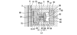
- FIG. 2 is an explanatory diagram showing the configuration of the flow rate adjusting mechanism and the state in which the first valve device of the flow rate adjusting mechanism is opened because the differential pressure between the crank chamber pressure and the storage chamber pressure is relatively large. is there.
- FIG. 3 shows the configuration of the flow rate adjusting mechanism described above, and the first valve device of the flow rate adjusting mechanism is eliminated because the differential pressure between the crank chamber pressure and the storage chamber pressure disappears or becomes very small when the operation of the air conditioner is OFF. It is explanatory drawing which shows the closed state.
- FIG. 1 is a cross-sectional view showing an example of the configuration of a variable capacity compressor in which a flow rate adjusting mechanism according to the present invention is used.
- FIG. 2 is an explanatory diagram showing the configuration of the flow rate adjusting mechanism and the state in which the first valve device of the flow rate adjusting mechanism
- FIG. 4 is an explanatory diagram showing the configuration of the flow rate adjusting mechanism and the state in which the relief valve is operated because the value of the differential pressure between the crank chamber pressure and the storage chamber pressure shows an abnormal value.
- FIG. 5 is a characteristic diagram showing a change in the valve opening degree of the flow rate adjusting mechanism as a whole from the state where the operation of the air flow rate adjusting mechanism, particularly the air conditioner, is turned on and started.
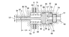
- FIG. 6 shows a configuration of a flow rate adjusting mechanism according to an embodiment different from the flow rate adjusting mechanism shown in FIGS. 2 to 4, and the flow rate adjustment is performed because the differential pressure between the crank chamber pressure and the storage chamber pressure is relatively large. It is explanatory drawing which shows the state which the 1st valve apparatus of the mechanism opened.
- FIG. 5 is a characteristic diagram showing a change in the valve opening degree of the flow rate adjusting mechanism as a whole from the state where the operation of the air flow rate adjusting mechanism, particularly the air conditioner, is turned on and started.
- FIG. 6 shows
- FIG. 1 shows an example of a variable capacity compressor 1 according to the present invention.
- the variable capacity compressor 1 is a clutchless that forms part of a refrigeration cycle that uses carbon dioxide as a refrigerant as a working fluid.
- a rear head 5 is mounted on the rear side (right side in FIG. 1) of the housing 2 via a valve plate 6.
- These cylinder housing 2, front head 4, and rear head 5 are in the axial direction of a cylinder bore 17 to be described later.
- the housing 7 is formed by inserting fastening bolts 58a and 58b appropriately along and joining and fixing them together. .
- a crank chamber 8 is defined in the housing 7 by the front head 4, the cylinder housing 2, and the cylinder block 3.
- a drive shaft 9 is housed.
- One end in the longitudinal direction protrudes from the front head 4 and a power transmission member (not shown) such as a pulley is fixed and is rotated by external power.
- a power transmission member such as a pulley is fixed and is rotated by external power.
- the one side end mentioned above of the drive shaft 9 is provided so that the boss
- the one end of the drive shaft 9 is sealed between the front head 4 and the front head 4 through a shaft sealing device 10 such as a mechanical seal provided between the front head 4 and the boss 4a of the front head 4.
- a thrust flange 11 provided on the outer peripheral surface
- a radial bearing 12 provided on the inner surface of the front head 4 inside the base end of the boss 4a
- a thrust bearing provided on the inner surface of the front head 4 13 is rotatably supported by the housing 7 via the 13.
- the other end of the drive shaft 9 opposite to the boss 4 a is rotatably supported by the housing 7 via a radial bearing 15 housed in the support recess 14 of the cylinder block 3.
- the cylinder block 3 is formed with cylinder bores 17 arranged at equal intervals on the circumference centering on the support recess 14 for supporting the drive shaft 9, and a single-headed piston 18 in the cylinder bore 17. Is inserted in the axial direction of the cylinder bore 17 so as to be able to reciprocate.
- the single-head piston 18 is provided with a piston ring 22 in this embodiment.
- the swash plate 19 is formed in a substantially cylindrical shape having a predetermined thickness.
- the swash plate 19 is housed in the crank chamber 8 and is swingably held on the drive shaft 9 via a pin 24 and a sleeve 44.
- a rotational force is transmitted from the drive shaft 9 via a rod 20 fixed to the drive shaft 9.
- a tail portion 18 a of a single-head piston 18 protruding into the crank chamber 8 is moored at a peripheral portion of the swash plate 19 via a pair of shoes 21, 21, and the rod 20 extends along the radial direction of the swash plate 19. It is slidably mounted via an interposition member 87 in a longitudinal hole 31 that extends and opens outward.
- An annular sleeve 44 is externally mounted on the drive shaft 9, and the sleeve 44 is swash plate by an elastic mechanism 47 such as a spring, one of which contacts the thrust flange 11 and the other contacts the projection of the sleeve 44.
- the swash plate 19 is biased along the axial direction of the drive shaft 9 so that the inclination angle of the 19 is relatively small.
- the rear head 5 is joined to the cylinder block 3 via the valve plate 6, thereby defining a suction chamber 25 and a discharge chamber 26 continuously formed around the suction chamber 25.
- the discharge chamber 26 communicates with the discharge port 16 opened on the outer surface of the rear head 5.
- the valve plate 6 has a suction hole 27 that communicates the suction chamber 25 and the compression chamber 23 via a suction valve 28, and a discharge hole 29 that communicates the discharge chamber 26 and the compression chamber 23 via a discharge valve 30. And are formed.
- the rear head 5 is provided with a pressure control valve (not shown) in an air supply passage (not shown) communicating the discharge chamber 26 and the crank chamber 8.
- crank chamber pressure When the pressure in the crank chamber 8 (hereinafter referred to as crank chamber pressure) is reduced by the pressure control valve, the differential pressure between the crank chamber pressure and the pressure in the compression chamber 23 of the single-headed piston 18 (hereinafter referred to as compression chamber pressure).
- compression chamber pressure The moment in the direction of increasing the stroke of the single-headed piston 18 caused by this increases, the swash plate 19 moves toward the front head 4 against the spring force of the elastic mechanism 47, and the swash plate 19 swings around the pin 24.
- the inclination angle of the swash plate 19 with respect to the surface along the radial direction of the drive shaft 9 is increased, the stroke amount of the one-head piston 18 is increased, and the discharge capacity is increased.
- crank chamber pressure the pressure in the crank chamber 8
- crank chamber pressure the pressure in the crank chamber 8
- the swash plate 19 moves to the rear head 5 side by the spring force of the elastic mechanism 47
- the swash plate 19 swings about the pin 24, and the diameter of the drive shaft 9 of the swash plate 19 is increased.
- the inclination angle with respect to the surface along the direction becomes small, the stroke amount of the single-head piston 18 becomes small, and the discharge capacity decreases.
- the drive shaft 9 is formed with the introduction hole 32 penetrating the drive shaft 9 along the radial direction thereof, and the drive is driven out of the introduction holes 32.
- a first discharge hole 33 extending along the axial direction of the drive shaft 9 is formed from a substantially central portion on the side along the radial direction of the shaft 9.
- the first discharge hole 33 has a uniform diameter portion 34a extending along the axial direction of the drive shaft 9 with the substantially same inner diameter, and the diameter of the first discharge hole 33 temporarily increases toward the rear head 5 in the axial direction of the drive shaft 9.
- the enlarged-diameter portion 34b is formed of a projecting portion 35 projecting along the axial direction of the drive shaft 9 from the rear head 5 side. It has become.
- one side extends in the projecting direction of the projecting portion 35, and opens to the enlarged diameter portion 34 b of the first discharge hole 33 at the approximate center of the projecting portion 35, and the other opens to the suction chamber 25.
- a second discharge hole 36 that communicates the discharge hole 33 and the suction chamber 25 is formed. Accordingly, the introduction passage 32, the first discharge hole 33, and the second discharge hole 36 constitute an extraction passage and a first oil separation mechanism (extraction OS). .
- oil separation first extraction OS
- first extraction OS oil separation from the working fluid flowing in from the introduction hole 32 is performed by the centrifugal force generated by the rotation of the drive shaft 9, and further, Even when the working fluid flows from the first discharge hole 33 into the second discharge hole 36, the oil is separated from the working fluid (second extraction OS).
- the introduction hole 32 is formed by penetrating along the radial direction of the drive shaft 9, the flow rate of the working fluid is reduced, and the oil separation performance as the execution of the first extraction OS is improved. Yes.
- the rear head 5 extends from the discharge chamber 26 in a direction perpendicular to the first discharge passage 37 extending in the same direction as the reciprocating direction of the single-headed piston 18, and A second discharge passage 38 communicating with the outlet 16 and relatively communicating with the first discharge passage 37 in the vicinity of the discharge port 16 is formed.
- a separation portion 39 is mounted and fixed at a position facing the portion connected to the first discharge passage 37.
- the separation portion 39 includes a small-diameter portion 40 extending along the direction in which the second discharge passage 38 extends, and the small-diameter portion 40 extends from the discharge hole side end to the discharge port 16 side in the extending direction.
- the first oil discharge mechanism 37 (discharge OS) is configured by the first discharge passage 37, the second discharge passage 38, and the separation portion 39.
- the rear head 5 is provided with a filter 42 below the separation portion 39 of the second discharge passage 38, and a first dust collecting pot 43 is formed below the filter 42.
- the oil separated by the second oil separation mechanism discharge OS
- the oil separated by the second oil separation mechanism communicates with the second discharge passage 38 below the filter 42 through the oil return passage 45 that communicates with the crank chamber 8. Then, the oil is returned to the crank chamber 8, and a second dust collection pot 46 is formed in the middle of the oil return passage 45.
- the working fluid discharged from the first discharge passage 37 to the second discharge passage 38 is allowed to flow outside the small diameter portion 40 of the separation portion 39.
- the inside of the small diameter portion 40 is lifted from the lower opening of the small diameter portion 40 and discharged from the discharge port 16.
- the oil contained in the working fluid can be reliably separated by causing the working fluid to flow while descending while turning around the outer periphery of the small diameter portion 40 at a high speed. Further, the oil separated through the oil return passage 45 can be returned to the crank chamber 8.
- a check valve (not shown) is arranged between the second oil separation mechanism and the discharge port 16 so that the working fluid is not discharged from the compressor when the operation of the air conditioner is OFF.
- variable capacity compressor 1 has a flow rate adjusting mechanism 50 disposed on the oil return passage 45.
- the flow rate adjusting mechanism 50 is disposed in the vicinity of the boundary portion between the rear head 5 and the valve plate 6 as shown in FIG. 1, and as shown in FIGS. 2 to 4, the valve plate 6.
- a recess 51 opened to the side is formed, and the cartridge is accommodated in the recess 51 like a cartridge.
- the flow rate adjusting mechanism 50 is connected to the upstream component member 53 having the inlet 52 connected to the upstream side of the oil return passage 45 and the downstream side of the oil return passage 45.
- a storage chamber 57 is defined inside.
- the downstream member 55 is formed with a passage 90 whose one end communicates with the outlet 54 and whose other end communicates with an escape passage described below.
- the storage chamber 57 includes a first valve device 59 that opens and closes the oil return passage 45 and a throttle passage 60 and a variable portion 61 that changes the length of the throttle passage 60 along the oil flow direction.
- the second valve device 62 is accommodated.
- the first valve device 59 includes a valve body 65, a valve seat 66, a spring receiving member 67, and a spring 68.
- the valve body 65 has a closed portion 63 having an outer shape with an outer diameter larger than the inner diameter size of the inlet 52 of the upstream side component 53, and has a larger dimension along the radial direction of the inlet 52 than the closed portion 63. It consists of a spring receiving portion 64 which is an outer shape.
- the valve seat 66 is formed by flattening the opening peripheral portion inside the storage chamber 57 of the inflow port 52 of the upstream side component member 53 so that the closing portion 63 of the valve body 65 can be brought into close contact therewith.
- the spring receiving member 67 is located on the downstream side of the storage chamber with respect to the valve body 65, and the dimension along the radial direction of the inflow port 52 is the spring receiving portion when compared with the spring receiving portion 64 of the valve body 65.
- the outer shape is the same as or larger than 64 and is basically fixed in the storage chamber 57.
- One side of the spring 68 is in contact with the spring receiving member 67 and the other side is in contact with the spring receiving portion 64 of the valve body 65.
- the spring 68 presses the valve body 65 toward the upstream component member 53 side by the spring force.
- the closing portion 63 of the valve body 65 can be in close contact with the valve seat 66 on the periphery of the inflow port 52. It is a size.
- the spring receiving member 67 has an extending portion 69 that extends toward the inflow port 52, and the spring 68 is packaged on the extending portion 69.
- the second valve device 62 includes a passage 70 that extends from the top in the extending direction of the extending portion 69 of the spring receiving member 67 to the outlet 54 side and is open on both sides thereof, and the spring receiving portion 64 of the valve body 65 is closed.
- a variable portion 61 that extends from the opposite side of the section side and whose axis in the extending direction coincides with the axis of the passage 70, and the depth at which the variable portion 61 is inserted into the passage 70 is variable.
- the length of the throttle passage 60 can be varied.
- the inner diameter dimension of the passage 70 and the opening diameter of the inflow port 52 are substantially the same.
- the depth at which the variable portion 61 is inserted into the passage 70 is adjusted using the spring force of the spring 68, and the valve body 65 is close to the spring receiving member 67 against the spring force of the spring 68. In this case, the depth at which the variable portion 61 is inserted into the passage 70 is increased, and the length of the throttle passage 60 is also increased as indicated by the dimension value L1 in FIG.
- the valve body 65 is farthest from the spring receiving member 67 due to the spring force of the spring 68, the depth at which the variable portion 61 is inserted into the passage 70 becomes shallow, and the length of the throttle passage 60 is also shown in FIG. 3, the value becomes smaller as indicated by the dimension value L2.
- the flow rate adjusting mechanism 50 includes a spring 72 called a disc spring or the like in the storage chamber 57.
- the spring 72 is interposed between the spring receiving member 67 and the surface of the downstream side component member 55 having the outlet 54.
- the spring receiving member 67 is supported in a form having a predetermined space between the surface 67 and the surface of the downstream component member 55 having the outlet 54.
- a relief valve is constituted by the outer surface of the spring receiving member 67 and the cylindrical component member 56. That is, the outer surface of the spring receiving member 67 and the cylindrical component member 56 are in close contact with each other by the spring 72 as shown in FIGS.
- the closing portion 63 of the valve body 65 of the first valve device 59 starts to be pressed from the inlet 52 side by a slightly generated differential pressure, and is separated from the valve seat 66 of the inlet 52.
- the proportion of the second valve device 62 inserted into the passage 70 of the variable portion 61 is relatively small, and the length of the throttle passage 60 is relatively short accordingly. As a result, the valve opening degree becomes maximum when the air conditioner is started.
- the differential pressure between the crank chamber pressure and the storage chamber pressure is increased and the ratio of being inserted into the passage 70 of the variable portion 61 of the second valve device 62 is temporarily. Since it becomes larger and the length of the throttle passage 60 becomes longer, the ratio of the valve opening degree as a whole of the flow rate adjusting mechanism 50 becomes smaller. Then, when the differential pressure between the crank chamber pressure and the storage chamber pressure reaches a predetermined pressure (for example, 8.5 MPa), the second valve device 62 regulates the insertion of the variable portion 61 further deeper.
- a predetermined pressure for example, 8.5 MPa
- the degree of opening of the flow rate adjusting mechanism 50 as a whole is simply that the closing portion 63 of the valve body 65 of the first valve device 59 opens when the closing portion 63 approaches or closes to the valve seat 66 of the inlet 52.
- the rate at which the variable portion 61 of the second valve device 62 is inserted into the passage 70 changes, and the length of the throttle passage 60 changes accordingly.
- the flow resistance is also taken into account.
- the predetermined gap of the throttle passage 60 is changed in accordance with the insertion depth of the variable portion 61 by, for example, tapering the variable portion 61 as will be described later, the change of the gap is taken into account.
- the relief valve constituted by the outer surface of the spring receiving member 67 and the cylindrical component member 56 functions. Since the high-pressure gas escapes to the crank chamber 8 side from the escape passage between the outer surface of the spring receiving member 67 and the cylindrical component member 56 and the passage 90, the difference between the crank chamber pressure and the storage chamber pressure that opens to the discharge chamber 26. In addition to reducing the pressure, the crank chamber pressure is increased and the inclination angle of the swash plate 19 is reduced.
- the characteristic line diagram of FIG. 5 shows the valve opening degree and the relief valve as a whole when the flow rate adjusting mechanism 50 works. Describing this special chart, it is desirable that the point A indicating the differential pressure until the first valve device 59 is opened is less than 1 MPa. As soon as the first valve device 59 is opened, the first valve device 59 is opened to the maximum valve opening degree indicated as point B. Thereafter, the valve opening degree gradually decreases to the point C of the predetermined differential pressure, and finally becomes constant. Furthermore, when the pressure reaches a point D of a predetermined differential pressure, the relief valve is activated.
- the valve opening degree of the flow rate adjusting mechanism 50 is 0, so that the high pressure gas of the working fluid passes through the return passage 45 from the discharge port 16 and the discharge region around it. Therefore, the inclination angle of the swash plate 19 when the operation of the air conditioner is OFF can be made smaller than when the fixed orifice is used, and power saving when the operation of the air conditioner is OFF can be achieved. .
- valve opening degree of the entire flow rate adjusting mechanism 50 is maximized when the operation of the air conditioner is restored.
- this flow rate adjusting mechanism 50 As shown in the characteristic diagram of FIG. 5, the line from point B to point C is linear as shown in FIG. 5 as (1), but is also shown as (2) in FIG.
- the predetermined gap of the throttle passage 60 is changed according to the insertion depth of the variable portion 61 in order to obtain desired characteristics. May be.
- the flow rate adjusting mechanism 50 has been described as being provided at the boundary portion of the rear head 5 with the valve plate 6, the flow adjusting mechanism 50 is not necessarily limited to this and may be on the oil return passage 45. However, the oil return passage 45 may be provided above the portion where the second dust collecting pot 46 branches, or provided so as to straddle the cylinder block 3 or between the cylinder block 3 and the rear head 5. Also good.
- FIG. 6 and 7 show another configuration of the flow rate adjusting mechanism 50.
- the flow rate adjusting mechanism 50 will be described.
- the same components as those of the flow rate adjusting mechanism 50 described above are denoted by the same reference numerals, and the description thereof is omitted.
- the flow rate adjusting mechanism 50 is the same as the flow rate adjusting mechanism 50 shown in FIG. 1 in that it is disposed on the oil return passage 45, but the flow rate adjusting mechanism 50 shown in FIG. Differently, it is arranged across the rear head 5 and the cylinder block 3.
- the flow rate adjusting mechanism 50 forms a recess 51 that opens to the valve plate 6 side with respect to the rear head 5, forms a through hole 6 a in the valve plate 6, and
- the recess 71 opened to the valve plate 6 side with respect to the block 3 the rear head 5, the valve plate 6 and the cylinder block 3 are appropriately combined while aligning the recess 51, the through hole 6a and the recess 71,
- a storage chamber 57 is directly defined inside the variable capacity compressor, a first valve device 59 for opening and closing the inlet 52 in the storage chamber 57, and a second passage having a throttle passage 60 having a variable length.
- the valve device 62 is housed.
- the storage chamber 57 has relatively small compartments 74 and 76 on the upstream side and the downstream side of the oil return passage 45 and communicates with the compartments 74 and 76 between the compartments 74 and 76.
- a large compartment 75 is provided.
- the compartment 74 contains a filter 77 for collecting dust, and a block body 78 having an inlet 52 to the compartment 75 is disposed on the upstream side of the compartment 75 so as to be in contact with the side of the compartment 74 of the compartment 75.
- the block body 78 is provided with an O-ring 79 on the outer peripheral surface, and the space between the block body 78 and the inner surface of the compartment 75 is hermetically sealed.
- the first valve device 59 includes a valve body 80 including a closing portion 81 and a spring receiving portion 82 that are larger than the inner diameter of the inlet 52 formed in the block body 78, and a storage chamber of the inlet 52 of the block body 78.
- the valve seat 66 is formed at the peripheral edge of the opening on the 57 side and can be in close contact with the closing portion 81, and the wall surface extends in the direction intersecting the axial direction of the oil return passage 45 on the boundary side of the compartment 75 with the compartment 76.
- a spring receiving portion 84 and a spring 68 are included.
- the spring 68 is in contact with the spring receiving portion 82 of the valve body 80 on one side and is in contact with the spring receiving portion 84 on the other side, and presses the valve body 80 toward the block body 78 by the spring force.
- the spring force is set to a size that allows the closing portion 81 of the valve body 80 to be in close contact with the valve seat 83 when the differential pressure between the crank chamber pressure and the pressure at the inlet 52 of the storage chamber is eliminated or close to it.
- a gap is formed between the outer peripheral surface of the valve body 80 and the inner surface of the compartment 75, and a notch 85 is formed on the outer peripheral surface of the valve body 80, thereby facilitating the flow of oil. I am trying.
- the gap between the outer peripheral surface of the valve body 80 and the inner surface of the compartment 75 is set to be smaller than the gap of the throttle passage 60.
- the second valve device 62 includes a compartment 76 and a variable portion 86 extending from the opposite side of the valve body 80 to the closing portion 81 side toward the compartment 76, and the variable portion 86 is provided in the compartment 76.
- the length of the throttle passage 60 can be varied by varying the depth at which the lens is inserted.
- the depth at which the variable portion 86 is inserted into the compartment 76 is also adjusted using the spring force of the spring 68 and linked to the distance from the inlet 52 of the closing portion 81 of the valve body 80. ing.
- the length of 60 also increases as shown by the dimension value L4 in FIG.
- the valve body 80 is farthest from the spring receiving portion 84 due to the spring force of the spring 68, the depth at which the variable portion 86 is inserted into the chamber 76 becomes relatively shallow, The length is also reduced as shown by the dimension value L5 in FIG.
- the inner diameter L6 of the compartment 76 and the inner diameter L7 of the inlet 52 shown in FIGS. 6 and 7 are the same.
- the differential pressure between the crank chamber pressure and the pressure in the storage chamber or the inlet 52 is 0 MPa or a value close to this.
- the closing portion 81 of the valve body 80 of the first valve device 59 is in close contact with the valve seat 66 of the inflow port 52 to close the inflow port 52, and the working fluid high-pressure gas from the discharge port 16 and its surrounding discharge region. Is prevented from flowing into the crank chamber 8 through the return passage 45.
- the closing portion 81 of the valve body 80 of the first valve device 59 starts to be pressed from the inlet 52 side by a slightly generated differential pressure, and is separated from the valve seat 66 of the inlet 52.
- the ratio of the variable portion 86 of the second valve device 62 inserted into the compartment 76 is relatively small, and the length of the throttle passage 60 is relatively short along with this, the entire flow rate adjusting mechanism 50 is reduced. As a result, the valve opening degree becomes the maximum at the start of the air conditioner operation.
- the differential pressure between the crank chamber pressure and the storage chamber pressure increases, and the ratio of being inserted into the compartment 76 of the variable portion 86 of the second valve device 62 is high. Since the length of the throttle passage 60 becomes longer for a while and the length of the throttle passage 60 becomes longer, the ratio of the degree of opening of the flow rate adjusting mechanism 50 as a whole also decreases. Then, when the differential pressure between the crank chamber pressure and the storage chamber pressure reaches a predetermined pressure (for example, 8.5 MPa), the second valve device 62 restricts insertion of the variable portion 86 further deeper. Thus, the length of the throttle passage 60 can be kept constant.
- valve opening degree as a whole of the flow rate adjusting mechanism 50 appears as a solid characteristic line shown in the characteristic diagram of FIG. 5, so that the same effect as the previous embodiment can be obtained. Can do.
- a heat insulating material 85 is disposed on the discharge chamber 26, the first discharge passage 37, the second discharge passage 38, and the peripheral wall of the suction chamber 25. It has become a thing. Thereby, it is possible to cut off heat conduction between the high-pressure and high-temperature working fluid flowing on the high-pressure side of the variable displacement compressor 1 and the low-pressure and low-temperature working fluid flowing on the low-pressure side of the variable displacement compressor 1. Thus, overheating of the working fluid in the suction region including a suction port (not shown) can be prevented.
Landscapes
- Engineering & Computer Science (AREA)
- Mechanical Engineering (AREA)
- General Engineering & Computer Science (AREA)
- Compressors, Vaccum Pumps And Other Relevant Systems (AREA)
- Compressor (AREA)
Abstract
【課題】可変オリフィスを備えたオイル戻し通路を有しながら、エアコンの運転がOFF時における斜板の最小傾斜角を相対的に小さな値に設定することができ、流量調整機構の開弁度もエアコンの運転をONした際にすぐに最大となることができると共に、流量調整機構の構造も簡易である可変容量型圧縮機を提供する。 【解決手段】可変容量型圧縮機1は、オイル戻し通路45の経路上に、オイル戻し通路45を開閉する開閉手段を有する第1の弁装置59と、絞り通路60を有すると共にこの絞り通路60のうちオイルの流動方向に沿った長さを変更することが可能な可変部61を有する第2の弁装置62と、これらの第1の弁装置59、第2の弁装置62を収納すると共にオイル分離のための分離部39側と連通するための流入口52及びクランク室8側と連通するための流出口54を開口させた収納室57とから成る流量調整機構50が設けられたものとする。
Description
この発明は、圧縮機の作動流体経路内を流動する作動流体中に混在するオイルを分離することが可能な構造を有する可変容量型の圧縮機に関する。
この種の圧縮機としては、吐出室の作動流体と潤滑油とを分離する潤滑油分離装置とこの潤滑油分離装置で分離された潤滑油をクランク室に戻すオイル戻し通路とを有すると共に、吐出室とクランク室との差圧に応じて開閉される可変オリフィス状の流量制御弁が前記オイル戻し通路に配設された構成の往復動型流体機械について、例えば特許文献1に示されるように既に公知になっている。
そして、潤滑油分離装置で分離されたオイルは差圧の力によりクランク室に戻るので、流量制御弁の開弁度が固定された場合には全ての運転条件下で適正なオイルの戻りを実現することが困難であったところ、この特許文献1に示される往復動型流体機械では、可変オリフィス状の流量制御弁について、高圧側と低圧側との差圧の値が小さいときには大きく、高圧側と低圧側との差圧の値が大きいときには小さくなるように開弁度を設定して、例えばオイルが戻り難い条件下では弁の開度が相対的に大きくなることを可能することによりオイル戻り量の適正化を図っている。
また、例えば特許文献2に示されるようなクラッチレス可変容量型圧縮機の場合、エアコンの運転がOFFのときには電磁制御弁への供給電流をなくすことで電磁制御弁の開弁度が全開となり、クランク室内の圧力が相対的に高くなることで、かかる圧縮機の斜板の傾斜角が最小の状態となる。これに対し、エアコンの運転を再びONにすると、電磁制御弁に電流が供給されて、電磁制御弁の開弁度が小さくなり、相対的にクランク室内の圧力が低下して、かかる圧縮機の斜板の傾斜角が大きくなり、復帰状態となる。
そして、上記特許文献2に示されるようなクラッチレス可変容量型圧縮機では、圧縮機は常時回転しているので、エアコンの運転がOFFの状態での消費動力を低減するために、斜板の最小傾斜角が復帰可能な限界位置までの範囲で小さくなるように設定されている。
更にまた、吐出通路中にオイル分離機構を備える圧縮機において、そのオイル分離機構は、分離筒と油分離室とから構成されると共に給油通路中に弁室とスプールとバネとによって構成された弁手段を有し、この弁室をスプールで第1感圧室と第2感圧室とに仕切り、これらの第1感圧室と第2感圧室とから受けるそれぞれの圧力差が増大した際に、スプールが弁室内を摺動して給油通路の開度が拡大し全開後に縮小することにより、吸入室への潤滑油の供給量が制御され、運転の停止時にはバネにより給油通路が遮断される構造のものが、例えば特許文献3に示されるように公知になっている。
すなわち、この特許文献3に示される圧縮機は、弁手段を可変オリフィス状とするにあたり、スプールに開いた横穴とハウジングの壁面に開いた横穴とが連通する開口面積がスプールの移動量に応じて変化することを利用した構造となっている。
しかしながら、特許文献1に示されるような往復動型流体機械では、エアコンの運転をONにして圧縮機の斜板の傾斜角が相対的に大きくなる復帰状態とする際には、流量制御弁の開弁度が全開であるため流量制御弁を通じて高圧側からクランク室に流動する高圧ガスの量が相対的に多くなり、圧縮機の斜板の傾斜角について復帰状態に戻すためには長時間を要することが知られているので、それを避けるために、固定オリフィス状の流量制御弁を用いる場合よりも斜板の最小傾斜角を相対的に大きく設定せざるを得ないという不具合を有していた。これに伴い、特許文献1に示される可変オリフィス状の流量制御弁では、エアコンの運転のOFF時における消費動力が相対的に大きくなり、エアコンの運転がOFF時以外の圧縮機の省動力効果を減殺するという不都合も生じていた。
また、特許文献3に示される圧縮機の可変オリフィス状の弁手段の構造では、高圧側と低圧側との差圧が次第に大きくなると、スプールがバネを押す方向に移動し、スプールに開いた横穴とハウジングの壁面に開いた横穴との開口面積も次第に大きくなり、更に差圧が大きくなると、上記開口面積は、最大となった後に次第に小さくなり、バネが最も縮小した状態で最小となるので、開口面積がすぐに最大にならないという不具合を有していた。
また、特許文献3に示される圧縮機の可変オリフィス状の弁手段の構造では、スプールに開いた横穴とハウジングの壁面に開いた横穴との相対的な位置関係で開口面積が決定されるので、スプール及びその開口部の配置を位置決め手段により高精度に定める必要があり、弁手段の構造が複雑になると共に、位置決め手段を通じて高圧側の冷媒とオイルとが低圧側に漏れるおそれもあった。
更に、特許文献3に示される圧縮機の可変オリフィス状の弁手段の構造では、本願出願人の調査結果によると、特許文献3に示される圧縮機のスプールに開いた横穴とハウジングの壁面に開いた横穴との開口面積は、開口形状を円形状に置き換えた場合の直径寸法(以下、等価直径と称する。)が0.15mmから0.35mmの範囲で可変するのが好適であると考えられるところ、開口の形状を円形状に置き換えた場合にこのような小さな等価直径の寸法に設定するには、各横穴の大きさも相対的に小さくする必要があった。そして、横穴の大きさを相対的に小さくする場合にはスプールの移動量も小さくする必要があるところ、このスプールの移動量を決定するのはバネであるが、特許文献3の図2及び図3に示されるバネのサイズと横穴の大きさとの関係では、上記の適宜な開口面積の可変を引き出すバネ力を得るための設計が困難であり、特許文献3に示される圧縮機に係る発明の実施可能性に疑問があった。
そこで、本発明は、エアコンの運転がOFF時以外における高圧側とクランク室とを結ぶオイル戻し通路上に配置された流量調整機構の機能を維持しつつ、エアコンの運転がOFF時には弁を閉じて圧縮機の斜板の傾斜角の復帰性を向上し、圧縮機の斜板の最小傾斜角を相対的に小さな値に設定することができ、且つ流量調整機構の開弁度もエアコンの運転をONした際にすぐに最大となることができ、しかも、流量調整機構の構造も簡易である可変容量型圧縮機、特にクラッチレス可変容量型圧縮機を提供することを目的とする。
この発明に係る可変容量型圧縮機は、ハウジングと、このハウジング内部に形成されたクランク室と、前記ハウジングに回転自在に支持されて外部の駆動力にて回転動する駆動軸と、前記クランク室に配されて前記駆動軸の回転に同期して回転する斜板と、斜板の回転に伴いシリンダボア内を往復動するピストンと、このピストンの往復動により前記シリンダボアに選択的に連通する吸入室及び吐出室とを有し、前記斜板の傾斜角を変更することにより吐出容量を制御する可変容量型圧縮機において、前記吐出室を含む吐出領域を設け、作動流体に混在するオイルを分離するオイル分離機構を前記吐出領域に設けると共にこのオイル分離機構によって分離されたオイルを前記クランク室に戻すオイル戻し通路を有し、前記オイル戻し通路上には、このオイル戻し通路を開閉する開閉手段を有する第1の弁装置と、絞り通路を有すると共にこの絞り通路のうちオイルの流動方向に沿った長さを変更することが可能な可変絞り手段を有する第2の弁装置と、これらの第1及び第2の弁装置を収納すると共に前記オイル分離機構側と連通するための流入口及び前記クランク室側と連通するための流出口を開口させた収納室とから成る流量調整機構が設けられていることを特徴としている(請求項1)。
これにより、第2の弁装置において、吐出領域等の高圧側とクランク室等の低圧側との差圧が小さいときに絞り通路のうちオイルの流動方向に沿った寸法が相対的に短くなり、吐出領域等の高圧側とクランク室等の低圧側との差圧が大きいときに絞り通路のうちオイルの流動方向に沿った寸法が相対的に長くなるよう設定することにより、エアコンの運転時におけるオイルのクランク室への戻り量の適正化を図ると共に、第1の弁装置において、エアコンの運転がOFF時には弁体が収納室の流入口を閉塞するように設定することにより、高圧ガスが流量調整機構を介してクランク室に流動することを回避して、斜板についてその傾斜角を増大させる復帰性を向上し、エアコンの運転がOFF時における斜板の最小傾斜角を相対的に小さくすることが可能である。
前記第1の弁装置の開閉手段は、前記流入口側に向けて弾性機構により付勢された弁体と、前記流入口のうち前記収納室内側の開口の周縁に形成されて前記弁体が密接する弁座とから構成されている(請求項2)。
これにより、エアコンの運転をOFFにした場合には、高圧側と低圧側との差圧がなくなるかとても小さくなるので、第1の弁装置の弁体に対し弾性機構による付勢力の方が差圧により生ずる押圧力よりも大きくなるため第1の弁装置の弁体が流入口の開口周縁に形成された弁座に密着して流入口を閉塞した状態となる。一方、エアコンの運転がOFF時以外の場合には、高圧側と低圧側との差圧が相対的に大きくなるので、第1の弁装置の弁体に対し弾性機構による付勢力の方よりも差圧により生ずる押圧力の方が大きくなるため第1の弁装置の弁体が流入口の開口周縁に形成された弁座から離れ流入口が開放された状態となる。
前記第2の弁装置の絞り手段は、一方が前記流入口側に開口すると共に他方が流出口側に開口した貫通孔と、この貫通孔の内面との間に所定の隙間を有しつつ軸方向に沿って移動可能に前記貫通孔に挿入されると共に前記入口側に向けて弾性機構により付勢された可変部とにより構成されて、前記可変部のうち前記貫通孔の軸方向に沿った面と前記貫通孔の内面との間に絞り通路が形成されると共に、前記可変部の前記貫通孔への挿入量を変えることで前記絞り通路のうちオイルの流動方向に沿った長さを可変するものとなっている(請求項3)。
これにより、吐出領域等の高圧側とクランク室等の低圧側との差圧が小さいときには、弾性機構による付勢力の方が差圧により生ずる押圧力よりも大きいため第2の弁装置の可変部は流入口側に移動するので、絞り通路のうちオイルの流動方向に沿った寸法が相対的に短くなり、吐出領域等の高圧側とクランク室等の低圧側との差圧が大きいときには、差圧により生ずる押圧力の方が弾性機構の付勢力よりも大きいため第2の弁装置の可変部は流出口側に移動するので、絞り通路のうちオイルの流動方向に沿った寸法が相対的に長くなることから、エアコンの運転時におけるオイルのクランク室への戻り量の適正化を図ることができる。
そして、前記第1の弁装置の弁体と前記第2の弁装置の可変部とは、前記第2の弁装置の可変部よりも前記第1の弁装置の弁体の方がオイルの流動方向の上流側に位置すると共に一体的に動くように形成されている(請求項4)。
これにより、第1の弁装置の弁体を付勢するための弾性機構と第2の弁装置の可変部を付勢するための弾性機構とについても共通化することができ、オイル戻り通路も第1の弁装置用のものと第2の弁装置用のものとを形成する必要がなくなる。
以上のように、これらの発明によれば、第2の弁装置において、吐出領域等の高圧側とクランク室等の低圧側との差圧が小さいときに絞り通路のうちオイルの流動方向に沿った寸法が相対的に短くなり、吐出領域等の高圧側とクランク室等の低圧側との差圧が大きいときに絞り通路のうちオイルの流動方向に沿った寸法が相対的に長くなるよう設定することにより、エアコンの運転時におけるオイルのクランク室への戻り量の適正化を図るという効果を維持することができる。そして、第1の弁装置において、エアコンの運転がOFF時には弁体が収納室の流入口を閉塞するように設定することにより、斜板についてその傾斜角を増大させる復帰性を向上し、エアコンの運転がOFF時における斜板の最小傾斜角を相対的に小さくすることが可能であるので、エアコンのOFF時でも圧縮機の省動力の要請に応えることができる。
特に請求項2に記載の発明によれば、エアコンの運転をOFFにした場合には、高圧側と低圧側との差圧がなくなるかとても小さくなることから、第1の弁装置の弁体に対し弾性機構による付勢力の方が差圧により生ずる押圧力よりも大きくなるため第1の弁装置の弁体が流入口の開口周縁に形成された弁座に密着して流入口を閉塞した状態となるので、吐出室を含む吐出領域からクランク室にエアコンの運転がOFF時にも関わらず高圧ガスが流量調整機構を介してクランク室に流入するのを回避することができる。その一方で、エアコンの運転がOFF以外の場合には、高圧側と低圧側との差圧が大きくなることから、第1の弁装置の弁体に対し弾性機構による付勢力の方よりも差圧により生ずる押圧力の方が大きくなるため第1の弁装置の弁体が流入口の開口周縁に形成された弁座から離れ流入口が開放された状態となるので、流量調整機構のオリフィス弁としての機能を確保することができる。
特に請求項3に記載の発明によれば、吐出領域等の高圧側とクランク室等の低圧側との差圧が小さいときには、弾性機構による付勢力の方が差圧により生ずる押圧力よりも大きいため第2の弁装置の可変部は流入口側に移動するので、絞り通路のうちオイルの流動方向に沿った寸法を相対的に短くすることができ、吐出領域等の高圧側とクランク室等の低圧側との差圧が大きいときには、差圧により生ずる押圧力の方が弾性機構の付勢力よりも大きいため第2の弁装置の可変部は流出口側に移動するので、絞り通路のうちオイルの流動方向に沿った寸法を相対的に長くすることができることから、エアコンの運転がON等、OFF以外の時におけるオイルのクランク室への戻り量の適正化を図ることができる。
特に請求項4に記載の発明によれば、第1の弁装置の弁体を付勢するための弾性機構と第2の弁装置の可変部を付勢するための弾性機構とについても共通化することができ、オイル戻り通路も第1の弁装置用のものと第2の弁装置用のものとを形成する必要がなくなるので、圧縮機の構造の簡略化、ひいては製造コストの相対的な削減を図ることができる。
以下、この発明の実施形態について添付図面を参照しながら説明する。
図1において、この発明に係る可変容量型圧縮機1の一例が示されており、この可変容量型圧縮機1は、作動流体たる冷媒として二酸化炭素を用いる冷凍サイクルの一部を構成するクラッチレス式のもので、略筒状のシリンダハウジング2と、このシリンダハウジング2内に固着されたシリンダブロック3と、シリンダハウジング2のフロント側(図1中、左側)に位置するフロントヘッド4と、シリンダハウジング2のリア側(図1中、右側)にバルブプレート6を介して組み付けられたリアヘッド5とを有し、これらのシリンダハウジング2、フロントヘッド4、及びリアヘッド5は後述するシリンダボア17の軸方向に沿って締結ボルト58a、58bを適宜挿通させて相互に接合し固定することにより、ハウジング7を構成している。
また、可変容量型圧縮機1は、フロントヘッド4と、シリンダハウジング2と、シリンダブロック3とによりハウジング7内にクランク室8が画成されている。このクランク室8には、長手方向の一方側端がフロントヘッド4から突出してプーリ等の図示しない動力伝達部材が固定されて、外部からの動力で回転する駆動軸9が収納されている。そして、駆動軸9の前述した一方側端は、フロントヘッド4の中央部を外側に突出するボス部4aを挿通するように設けられている。
更に、駆動軸9の前記一方側端は、フロントヘッド4のボス部4aとの間に設けられたメカクニカルシール等の軸封装置10を介してフロントヘッド4との間が気密性良く封じられていると共に、外周面に外装されたスラストフランジ11、フロントヘッド4のうちボス部4aの基端よりも内側の内面に設けられたラジアル軸受12、及びフロントヘッド4の内面に設けられたスラスト軸受13を介してハウジング7に回動自在に支持されている。そして、駆動軸9のボス部4aとは反対側となる他方側端は、シリンダブロック3の支持凹部14に収納されたラジアル軸受15を介してハウジング7に回動自在に支持されている。
更にまた、シリンダブロック3には、駆動軸9を支持する前記支持凹部14を中心とする円周上に等間隔に配されたシリンダボア17が形成されていると共にこのシリンダボア17内には片頭ピストン18がシリンダボア17の軸方向に沿って往復動可能に挿入されている。片頭ピストン18は、この実施例ではピストンリング22を具備したものとなっている。
斜板19は、所定の厚みを有する略円柱状に形成されているもので、クランク室8に収納されて、駆動軸9にピン24とスリーブ44とを介して揺動自在に保持されると共に駆動軸9に固着されたロッド20を介して駆動軸9から回転力が伝達されるようになっている。更に、斜板19の周縁部分には、一対のシュー21、21を介してクランク室8に突出した片頭ピストン18の尾部18aが係留されていると共にロッド20は斜板19の径方向に沿って延びて外方に開口した縦孔31内に介在部材87を介して摺動可能に装着されている。
そして、駆動軸9には環状のスリーブ44が外装されており、このスリーブ44は一方側がスラストフランジ11に当接し、他方が当該スリーブ44の突起に当接したバネ等の弾性機構47により斜板19の傾斜角を相対的に小さくするように駆動軸9の軸方向に沿って斜板19側に付勢されている。
これにより、駆動軸9が回転すると、これに同期して斜板19が一体に回転し、この回転運動がシュー21、21を介して片頭ピストン18の往復運動に変換され、片頭ピストン18の往復動によりシリンダボア17内において片頭ピストン18とバルブプレート6との間に形成される圧縮室23の容積が変更されるようになっている。
リアヘッド5は、シリンダブロック3とバルブプレート6を介して接合することにより、吸入室25とこの吸入室25の周囲に連続的に形成された吐出室26とが画成されている。吐出室26は、リアヘッド5の外面に開口した吐出口16と連通している。また、バルブプレート6には、吸入室25と圧縮室23とを吸入弁28を介して連通する吸入孔27と、吐出室26と圧縮室23とを吐出弁30を介して連通する吐出孔29とが形成されている。そして、リアヘッド5には、吐出室26とクランク室8とを連通する給気通路(図示せず。)に圧力制御弁(図示せず。)が装着されている。
これにより、駆動軸9が回転すると、その回転力はロッド20を介して斜板19に伝達されて斜板19が回転し、上記したように片頭ピストン18がシリンダボア17内を往復動するので、片頭ピストン18の下降行程においては吸入室25内の作動流体が吸入孔27を介して圧縮室23に吸入され、片頭ピストン18の上昇行程においては圧縮室23内の作動流体が圧縮されて吐出孔29を介して吐出室26へ吐出されることとなる。
そして、圧力制御弁によりクランク室8内の圧力(以下、クランク室圧。)を減少させると、クランク室圧と片頭ピストン18の圧縮室23の圧力(以下、圧縮室圧。)との差圧により生ずる片頭ピストン18のストロークを増大させる方向のモーメントが大きくなり、斜板19が弾性機構47のバネ力に抗してフロントヘッド4側に移動し、斜板19がピン24を中心に揺動して斜板19の駆動軸9の径方向に沿った面に対する傾斜角が大きくなり、片頭ピストン18のストローク量が大きくなって、吐出容量が増大する。これに対し、圧力制御弁によりクランク室8内の圧力(以下、クランク室圧。)を増大させると、クランク室圧と圧縮室圧との差圧により生ずる片頭ピストン18のストロークを減少させる方向のモーメントが大きくなり、斜板19が弾性機構47のバネ力により斜板19がリアヘッド5側に移動して、斜板19がピン24を中心に揺動して斜板19の駆動軸9の径方向に沿った面に対する傾斜角が小さくなり、片頭ピストン18のストローク量が小さくなって、吐出容量が減少する。
上記した可変容量型圧縮機1において、この実施形態では、駆動軸9に、この駆動軸9をその径方向に沿って貫通する導入孔32が形成されていると共に、この導入孔32のうち駆動軸9の径方向に沿った側の略中心部位から駆動軸9の軸方向に沿って延びる第1の排出孔33が形成されている。この第1の排出孔33は、内径寸法が略同じまま駆動軸9の軸方向に沿って延出する均等径部34aと駆動軸9の軸方向のうちリアヘッド5側に向かうに従い暫時拡径する拡径部34bとから成ると共に、この拡径部34bはリアヘッド5側から駆動軸9の軸方向に沿って突出した突出部35がシリンダブロック3に形成されることによりその中央が窪んだ画室となっている。
そして、一方が突出部35の突出方向に延びて、この突出部35の略中央において第1の排出孔33の拡径部34bに開口すると共に他方が吸入室25に開口することにより、第1の排出孔33と吸入室25とを連通する第2の排出孔36が形成されている。これにより、これらの導入孔32、第1の排出孔33、及び第2の排出孔36によって抽気通路が構成されると共に第1のオイル分離機構(抽気OS)が構成されるものとなっている。この第1のオイル分離機構(抽気OS)においては、駆動軸9の回転により生ずる遠心力によって導入孔32から流入した作動流体からのオイルの分離(第1の抽気OS)が実行され、更に、第1の排出孔33から第2の排出孔36に作動流体が流入する段階でも作動流体からのオイルの分離(第2の抽気OS)が実行される。しかも、導入孔32が駆動軸9の径方向に沿って貫通することにより形成されているので、作動流体の流速が低下し、上記第1の抽気OSの実行としてのオイル分離性を向上させている。
また、リアヘッド5は、吐出室26から片頭ピストン18の往復動の方向と同方向に延びる第1の吐出通路37と、この第1の吐出通路37と直交するように延出するもので、吐出口16と連通すると共に第1の吐出通路37とは相対的に吐出口16近傍にて連通している第2の吐出通路38とが形成されている。そして、この第2の吐出通路38内には、第1の吐出通路37に接続する部位と対峙する位置に分離部39が装着、固定されている。この分離部39は、第2の吐出通路38の延出する方向に沿って延出する小径部40と、この小径部40のうちその延出方向のうち吐出孔側端から吐出口16側に向かうに従い第2の吐出通路38の内面に当接するように拡径した拡径部41とから構成されている。これにより、これらの第1の吐出通路37、第2の吐出通路38及び分離部39によって第2のオイル分離機構(吐出OS)が構成されたものとなっている。
更に、この実施形態では、リアヘッド5は、第2の吐出通路38の分離部39よりも下方にフィルタ42が配されていると共に、このフィルタ42よりも下方に第1の集塵ポット43が形成されている。そして、この第2のオイル分離機構(吐出OS)で分離されたオイルは、第2の吐出通路38とそのフィルタ42よりも下方側にて連通すると共にクランク室8とも連通するオイル戻し通路45を経てクランク室8内に戻されるようになっており、このオイル戻し通路45の途中には第2の集塵ポット46が形成されている。
このような第2のオイル分離機構(吐出OS)の構成とすることにより、第1の吐出通路37から第2の吐出通路38に吐出された作動流体は、分離部39の小径部40の外周を下方に向けて螺旋状に旋回した後、小径部40の下方開口から小径部40の内部を上昇して吐出口16から吐出される。作動流体にこのような小径部40の外周を高速で旋回しつつ下降した後、上昇するという流れを経るようにすることにより、作動流体内に含まれるオイルを確実に分離させることができる。更に、オイル戻し通路45を介して分離されたオイルをクランク室8に戻すことができる。尚、第2のオイル分離機構と吐出口16との間には、図示しない逆止弁が配置され、エアコンの運転がOFFの時に圧縮機から作動流体が排出されないようになっている。
ところで、可変容量型圧縮機1は、オイル戻し通路45の経路上に流量調整機構50が配置されている。流量調整機構50は、この実施形態では図1に示されるようにリアヘッド5のうちバルブプレート6との境界部分近傍に配置されているもので、図2から図4に示されるようにバルブプレート6側に開口した窪み51を形成して、この窪み51内にカートリッジ的に収納されている。
そして、流量調整機構50は、図2から図4に示されるように、オイル戻し通路45の上流側と接続する流入口52を有する上流側構成部材53と、オイル戻し通路45の下流側と接続する流出口54を有する下流側構成部材55と、これらの上流側構成部材53側及び下流側構成部材55側に開口した筒状構成部材56とを有して構成され、これらの構成部材53、55、56を組み付けることにより内部に収納室57が画成されるものとなっている。下流側部材55には、一方側端が流出口54と連通し、他方側端が下記する逃がし通路と連通する通路90が形成されている。
収納室57には、オイル戻し通路45を開閉する第1の弁装置59と、絞り通路60を有すると共にこの絞り通路60のうちオイルの流動方向に沿った長さを変更する可変部61を有する第2の弁装置62とが収納されている。
第1の弁装置59は、弁体65と、弁座66と、バネ受け部材67と、バネ68とで構成されている。弁体65は、上流側構成部材53の流入口52の内径寸法よりも大きな外径寸法の外形状を有する閉塞部63及びこの閉塞部63よりも流入口52の径方向に沿った寸法の大きな外形状であるバネ受け部64から成っている。弁座66は、上流側構成部材53の流入口52のうち収納室57内側の開口周縁部位を弁体65の閉塞部63が密着可能なように平坦にすることで形成されている。バネ受け部材67は、弁体65よりも収納室のうち下流側に位置したもので、弁体65のバネ受け部64と比較した場合に流入口52の径方向に沿った寸法がバネ受け部64と同じかより大きな外形状をなし、収納室57において基本的に固定された状態にある。バネ68は、一方側がバネ受け部材67に当接し、他方側が弁体65のバネ受け部64に当接したもので、バネ力により弁体65を上流側構成部材53側に押圧している一方で、そのバネ力はクランク室圧と収納室圧との差圧がなくなったかそれに近い状態のときに、弁体65の閉塞部63が流入口52の周縁の弁座66に密着することができる大きさとなっている。そして、この実施例ではバネ受け部材67は流入口52側に延出した延出部69を有し、バネ68はこの延出部69に外装されたかたちとなっている。
第2の弁装置62は、バネ受け部材67の延出部69の延出方向の頂部から流出口54側まで延びると共にその両側が開口した通路70と、弁体65のバネ受け部64の閉塞部側とは反対側から延出し、その延出方向の軸線が通路70の軸線と一致している可変部61とを有し、通路70内に可変部61が挿入される深度を可変することにより絞り通路60の長さが可変するようになっている。通路70の内径寸法と流入口52の開口径とは略同じである。そして、可変部61が通路70内に挿入される深度は、バネ68のバネ力を利用して調節されるもので、弁体65がバネ68のバネ力に抗してバネ受け部材67に近接している場合には、通路70内に可変部61が挿入される深度が深くなって、絞り通路60の長さも図2において寸法値L1として示されるように大きくなる。反対に、弁体65がバネ68のバネ力により最もバネ受け部材67から離れている場合には、通路70内に可変部61が挿入される深度が浅くなって、絞り通路60の長さも図3において寸法値L2として示されるように小さくなる。
また、流量調整機構50は、この実施形態では、収納室57内に例えば皿バネ等と称されるバネ72を備えている。このバネ72は、バネ受け部材67と下流側構成部材55の流出口54を有する面との間に介在しているもので、通常時では図2及び図3に示されるように、バネ受け部材67と下流側構成部材55の流出口54を有する面との間に所定の空間を有したかたちでバネ受け部材67を支持している。そして、バネ受け部材67の外面と筒状構成部材56とによってリリーフ弁が構成されている。すなわち、バネ受け部材67の外面と筒状構成部材56とは、バネ72により通常時では図2及び図3に示されるように密着しているが、クランク室圧と収納室圧との差圧が異常に大きくなると、バネ受け部材67がバネ72のバネ力に抗して流出口54側に変位して、図4に示されるように、筒状構成部材56とバネ受け部材67の外面との間に、下流側構成部材55に形成された通路90及び流出口54と連通した、高圧ガスの逃がし通路が一時的に形成される。尚、バネ受け部材67が流出口54側に変位した場合には、通路70内に可変部61が挿入される深度が最も深くなって、絞り通路60の長さも図4において寸法値L3として示されるように大きくなる。
そして、エアコンの運転がOFFの状態では、クランク室圧と収納室の流入口52の圧力との差圧が0MPa若しくはこれに近い値となるところ、第1の弁装置59の弁体65の閉塞部63は、流入口52の弁座66に密着して流入口52を閉塞し、吐出口16及びその周辺の吐出領域から作動流体の高圧ガスが戻し通路45を通ってクランク室8に流入することが回避される。
更に、エアコンの運転の起動時には、第1の弁装置59の弁体65の閉塞部63は、わずかに発生する差圧により流入口52側から押圧されはじめ、流入口52の弁座66から離れつつあるが、第2の弁装置62の可変部61の通路70内に挿入される割合は相対的に小さく、これに伴い絞り通路60の長さも相対的に短いので、流量調整機構50の全体として見た場合には開弁度がエアコンの運転の起動時に最大となる。
エアコンの起動後、エアコンの運転がONの状態には、クランク室圧と収納室圧との差圧が大きくなり第2の弁装置62の可変部61の通路70内に挿入される割合が暫時大きくなってゆき、絞り通路60の長さも長くなってくるので、流量調整機構50の全体としての開弁度の割合も小さくなってゆく。そして、クランク室圧と収納室圧との差圧が所定の圧力(例えば8.5MPa)に到達すると、第2の弁装置62は、可変部61がそれ以上深く挿入されるのを規制する手段として、弁体65の流出口54側が延出部69の流入口52側と当接する構成となっており、これにより、絞り通路60の長さを一定に保つことができる。ここで、流量調整機構50の全体としての開弁度とは、単に第1の弁装置59の弁体65の閉塞部63が流入口52の弁座66に遠近するにあたっての閉塞部63の開度のみならず、第2の弁装置62の可変部61が通路70に挿入される割合が変わり、これに伴い絞り通路60の長さが可変することで変わってくる、絞り通路60内での流路抵抗も加味したものとして示している。さらに、後述するように可変部61にテーパを付ける等によって、絞り通路60の所定隙間を可変部61の挿入深度に応じて変化さる場合にはこの隙間の変化も加味したものとして示される。
一方、更に、クランク室圧と収納室圧との差圧が上昇し異常な数値を示す場合には、バネ受け部材67の外面と筒状構成部材56とで構成されたリリーフ弁が機能して、バネ受け部材67の外面と筒状構成部材56との間の逃がし通路及び通路90から高圧ガスがクランク室8側に抜けるので、クランク室圧と吐出室26に開口する収納室圧との差圧を小さくする上に、クランク室圧を上昇させ、斜板19の傾斜角を小さくする。
この流量調整機構50全体としての開弁度及びリリーフ弁が働いた場合を特性線にして表したのが図5の特性線図である。この特選線図を説明すると、第1の弁装置59が開くまでの差圧を示すA点は、1MPa未満であることが望ましい。この第1の弁装置59が開くと、すみやかに第1の弁装置59は、B点として示される最大開弁度まで開く。その後、所定差圧のC点まで徐々に開弁度が低下し、最後は一定となる。更に、所定差圧のD点まで達するとリリーフ弁が作動する。
以上によれば、エアコンの運転がOFF時では流量調整機構50の開弁度が0であるため吐出口16及びその周辺の吐出領域から作動流体の高圧ガスが戻し通路45を通ってクランク室8に流入することがないので、エアコンの運転がOFF時の斜板19の傾斜角を、固定オリフィスを用いる場合よりも小さくすることができ、エアコンの運転のOFF時における省動力を図ることができる。
また、エアコンの運転の復帰時に流量調整機構50の全体としての開弁度が最大となることが好ましいところ、この流量調整機構50の構造を採ることにより図5の特性線図に示されるようにエアコンの運転の復帰時に流量調整機構50の全体としての開弁度を最大にすることを実現している。図5で示される特性線のうちB点からC点まで至る線部分は、図5で(1)として示されるように直線的であっても、同じく図5で(2)として示されるように曲線的であっても良いものであり、例えば可変部61に対しわずかにテーパを付けることにより、所望の特性を得るために絞り通路60の所定隙間を可変部61の挿入深度に応じて変化させても良い。
尚、流量調整機構50は、リアヘッド5のうちバルブプレート6との境界部位に設けるとして説明したが、必ずしもこれに限定されず、オイル戻し通路45の経路上であれば良いもので、例えば、図示しないが、オイル戻し通路45のうち第2の集塵ポット46が分岐する部位よりも上方に設けても良いし、シリンダブロック3内あるいはシリンダブロック3とリアヘッド5とに跨がるように設けても良い。
図6及び図7において、流量調整機構50の別の構成が示されている。以下、この流量調整機構50について説明する。但し、先述した流量調整機構50と同様の構成については同一の符号を付してその説明を省略する。
この流量調整機構50は、図1に示される流量調整機構50と対比するに、オイル戻し通路45の経路上に配置されている点では共通するが、図1に示される流量調整機構50とは異なって、リアヘッド5とシリンダブロック3とに跨がって配置されているものである。
すなわち、流量調整機構50は、図6及び図7に示されるように、リアヘッド5に対しバルブプレート6側に開口した窪み51を形成し、バルブプレート6に貫通孔6aを形成し、更に、シリンダブロック3に対しバルブプレート6側に開口した窪み71を形成することで、リアヘッド5、バルブプレート6及びシリンダブロック3を窪み51、貫通孔6a、窪み71の位置合わせをしつつ適宜組み合わせることにより、可変容量型圧縮機内部に直接的に収納室57を画成して、この収納室57に流入口52を開閉する第1の弁装置59と、長さが可変する絞り通路60を有する第2の弁装置62とを収納した構成となっている。
収納室57は、オイル戻し通路45の上流側と下流側とに相対的に小さな画室74、76を有すると共に画室74と画室76との間にこれらの画室74、76と連通する、相対的に大きな画室75を有している。画室74は集塵用のフィルタ77が収納されていると共に、画室75の上流側には画室75への流入口52を有するブロック体78が画室75の画室74側面と接するように配置されている。このブロック体78は、外周面にOリング79が配されて、ブロック体78と画室75の内面との間が気密性良くシールされている。
第1の弁装置59は、ブロック体78に形成された流入口52の内径寸法よりも大きな閉塞部81及びバネ受け部82から成る弁体80と、ブロック体78の流入口52のうち収納室57側の開口周縁部位に形成されて閉塞部81が密着可能な弁座66と、画室75のうち画室76との境界側にてオイル戻し通路45の軸方向と交差する方向に延びる壁面による成るバネ受け部84と、バネ68とで構成されている。バネ68は、一方側が弁体80のバネ受け部82に当接し、他方側がバネ受け部84に当接したもので、バネ力により弁体80をブロック体78側に押圧している一方で、そのバネ力がクランク室圧と収納室の流入口52の圧力との差圧がなくなったかそれに近い状態のときに弁体80の閉塞部81が弁座83に密着することができる大きさに設定されている。この実施形態では、弁体80の外周面と画室75の内面との間に隙間が形成されていると共に弁体80の外周面には切り欠き85が形成されており、オイルの流れの円滑化を図っている。弁体80の外周面と画室75の内面との間の隙間は、絞り通路60の隙間よりも小さくなるように設定されている。
第2の弁装置62は、画室76と、弁体80のうち閉塞部81側とは反対側から画室76に向けて延出した可変部86とで構成されて、画室76内に可変部86が挿入される深度を可変することにより絞り通路60の長さが可変するようになっている。そして、可変部86が画室76内に挿入される深度も、バネ68のバネ力を利用して調節されると共に、弁体80の閉塞部81の流入口52からの距離と連動するものとなっている。
すなわち、弁体80がバネ68のバネ力に抗してバネ受け部84に近接している場合には、画室76内に可変部86が挿入される深度が相対的に深くなって、絞り通路60の長さも図6において寸法値L4として示されるように大きくなる。反対に、弁体80がバネ68のバネ力により最もバネ受け部84から離れている場合には、画室76内に可変部86が挿入される深度が相対的に浅くなって、絞り通路60の長さも図7において寸法値L5として示されるように小さくなる。
そして、図6及び図7に示される画室76の内径寸法L6と流入口52の内径寸法L7とは同じになっている。
以上のような流量調整機構50の構成とすることにより、エアコンの運転がOFFの状態では、クランク室圧と収納室や流入口52の圧力との差圧が0MPa若しくはこれに近い値となるところ、第1の弁装置59の弁体80の閉塞部81は、流入口52の弁座66に密着して流入口52を閉塞し、吐出口16及びその周辺の吐出領域から作動流体の高圧ガスが戻し通路45を通ってクランク室8に流入することが回避される。
そして、エアコンの運転の起動時には、第1の弁装置59の弁体80の閉塞部81は、わずかに発生する差圧により流入口52側から押圧されはじめ、流入口52の弁座66から離れつつあるが、第2の弁装置62の可変部86の画室76内に挿入される割合は相対的に小さく、これに伴い絞り通路60の長さも相対的に短いので、流量調整機構50の全体としての開弁度がエアコンの運転の起動時に最大となる。
エアコンの起動後、エアコンの運転がONの状態には、クランク室圧と収納室圧との差圧が大きくなり、第2の弁装置62の可変部86の画室76内に挿入される割合が暫時大きくなってゆき、絞り通路60の長さも長くなってくるので、流量調整機構50の全体としての開弁度の割合も小さくなってゆく。そして、クランク室圧と収納室圧との差圧が所定の圧力(例えば8.5MPa)に到達すると、第2の弁装置62は、可変部86がそれ以上深く挿入されるのを規制する構成となっており、これにより、絞り通路60の長さを一定に保つことができる。
このため、この実施形態でも、流量調整機構50の全体としての開弁度は、図5の特性線図で示される実線の特性線として表れるので、先の実施形態と同様の作用効果を得ることができる。
そして、この可変容量型圧縮機1は、図1に示されるように、吐出室26、第1の吐出通路37及び第2の吐出通路38、並びに吸入室25の周壁に断熱材85を配したものとなっている。これにより、可変容量型圧縮機1の高圧側を流動する高圧・高温の作動流体と可変容量型圧縮機1の低圧側を流動する低圧・低温の作動流体との熱伝導を遮断することが可能となり、図示しない吸入口を含む吸入領域での作動流体の過熱を防止することが可能となっている。
1 可変容量型圧縮機
7 ハウジング
8 クランク室
9 駆動軸
17 シリンダボア
18 片頭ピストン
19 斜板
23 圧縮室
25 吸入室
26 吐出室
39 分離部
45 オイル戻し通路
50 流量調整機構
52 流入口
54 流出口
57 収納室
59 第1の弁装置
60 絞り通路
61 可変部
62 第2の弁装置
65 弁体
66 弁座
68 バネ
70 通路
76 画室
80 弁体
86 可変部
7 ハウジング
8 クランク室
9 駆動軸
17 シリンダボア
18 片頭ピストン
19 斜板
23 圧縮室
25 吸入室
26 吐出室
39 分離部
45 オイル戻し通路
50 流量調整機構
52 流入口
54 流出口
57 収納室
59 第1の弁装置
60 絞り通路
61 可変部
62 第2の弁装置
65 弁体
66 弁座
68 バネ
70 通路
76 画室
80 弁体
86 可変部
Claims (4)
- ハウジングと、このハウジング内部に形成されたクランク室と、前記ハウジングに回転自在に支持されて外部の駆動力にて回転動する駆動軸と、前記クランク室に配されて前記駆動軸の回転に同期して回転する斜板と、斜板の回転に伴いシリンダボア内を往復動するピストンと、このピストンの往復動により前記シリンダボアに選択的に連通する吸入室及び吐出室とを有し、前記斜板の傾斜角を変更することにより吐出容量を制御する容量可変型圧縮機において、
前記吐出室を含む吐出領域を設け、作動流体に混在するオイルを分離するオイル分離機構を前記吐出領域に設けると共にこのオイル分離機構によって分離されたオイルを前記クランク室に戻すオイル戻し通路を有し、
前記オイル戻し通路上には、このオイル戻し通路を開閉する開閉手段を有する第1の弁装置と、絞り通路を有すると共にこの絞り通路のうちオイルの流動方向に沿った長さを変更することが可能な可変絞り手段を有する第2の弁装置と、これらの第1及び第2の弁装置を収納すると共に前記オイル分離機構側と連通するための流入口及び前記クランク室側と連通するための流出口を開口させた収納室とから成る流量調整機構が設けられていることを特徴とする容量型圧縮機。 - 前記第1の弁装置の開閉手段は、前記流入口側に向けて弾性機構により付勢された弁体と、前記流入口のうち前記収納室内側の開口の周縁に形成されて前記弁体が密接する弁座とから構成されていることを特徴とする請求項1に記載の可変容量型圧縮機。
- 前記第2の弁装置の絞り手段は、一方が前記流入口側に開口すると共に他方が流出口側に開口した貫通孔と、この貫通孔の内面との間に所定の隙間を有しつつ軸方向に沿って移動可能に前記貫通孔に挿入されると共に前記入口側に向けて弾性機構により付勢された可変部とにより構成されて、前記可変部のうち前記貫通孔の軸方向に沿った面と前記貫通孔の内面との間に絞り通路が形成されると共に、前記可変部の前記貫通孔への挿入量を変えることで前記絞り通路のうちオイルの流動方向に沿った長さを可変することを特徴とする請求項1に記載の可変容量型圧縮機。
- 前記第1の弁装置の弁体と前記第2の弁装置の可変部とは、前記第2の弁装置の可変部よりも前記第1の弁装置の弁体の方がオイルの流動方向の上流側に位置すると共に一体的に動くように形成されていることを特徴とする請求項1から請求項3のいずれかに記載の可変容量型圧縮機。
Applications Claiming Priority (2)
| Application Number | Priority Date | Filing Date | Title |
|---|---|---|---|
| JP2009138936A JP2010285898A (ja) | 2009-06-10 | 2009-06-10 | 可変容量型圧縮機 |
| JP2009-138936 | 2009-06-10 |
Publications (1)
| Publication Number | Publication Date |
|---|---|
| WO2010143346A1 true WO2010143346A1 (ja) | 2010-12-16 |
Family
ID=43308609
Family Applications (1)
| Application Number | Title | Priority Date | Filing Date |
|---|---|---|---|
| PCT/JP2010/002463 WO2010143346A1 (ja) | 2009-06-10 | 2010-04-05 | 可変容量型圧縮機 |
Country Status (2)
| Country | Link |
|---|---|
| JP (1) | JP2010285898A (ja) |
| WO (1) | WO2010143346A1 (ja) |
Families Citing this family (1)
| Publication number | Priority date | Publication date | Assignee | Title |
|---|---|---|---|---|
| JP2019157810A (ja) * | 2018-03-16 | 2019-09-19 | サンデン・オートモーティブコンポーネント株式会社 | 圧縮機 |
Citations (5)
| Publication number | Priority date | Publication date | Assignee | Title |
|---|---|---|---|---|
| JPH0326876A (ja) * | 1989-06-22 | 1991-02-05 | Nippondenso Co Ltd | 斜板型可変容量圧縮機 |
| JPH06249146A (ja) * | 1993-02-19 | 1994-09-06 | Toyota Autom Loom Works Ltd | 斜板式圧縮機 |
| JP2007192154A (ja) * | 2006-01-20 | 2007-08-02 | Sanden Corp | 往復動型流体機械 |
| JP2008133810A (ja) * | 2006-11-29 | 2008-06-12 | Toyota Industries Corp | 圧縮機 |
| JP2009114901A (ja) * | 2007-11-05 | 2009-05-28 | Toyota Industries Corp | 可変容量圧縮機 |
-
2009
- 2009-06-10 JP JP2009138936A patent/JP2010285898A/ja active Pending
-
2010
- 2010-04-05 WO PCT/JP2010/002463 patent/WO2010143346A1/ja active Application Filing
Patent Citations (5)
| Publication number | Priority date | Publication date | Assignee | Title |
|---|---|---|---|---|
| JPH0326876A (ja) * | 1989-06-22 | 1991-02-05 | Nippondenso Co Ltd | 斜板型可変容量圧縮機 |
| JPH06249146A (ja) * | 1993-02-19 | 1994-09-06 | Toyota Autom Loom Works Ltd | 斜板式圧縮機 |
| JP2007192154A (ja) * | 2006-01-20 | 2007-08-02 | Sanden Corp | 往復動型流体機械 |
| JP2008133810A (ja) * | 2006-11-29 | 2008-06-12 | Toyota Industries Corp | 圧縮機 |
| JP2009114901A (ja) * | 2007-11-05 | 2009-05-28 | Toyota Industries Corp | 可変容量圧縮機 |
Also Published As
| Publication number | Publication date |
|---|---|
| JP2010285898A (ja) | 2010-12-24 |
Similar Documents
| Publication | Publication Date | Title |
|---|---|---|
| WO2018124156A1 (ja) | 容量制御弁 | |
| US8439652B2 (en) | Suction throttle valve for variable displacement type compressor | |
| US20050265853A1 (en) | Control valve for variable displacement compressor | |
| KR101729076B1 (ko) | 용량 가변형 사판식 압축기 | |
| JPWO2019142931A1 (ja) | 容量制御弁 | |
| US10815980B2 (en) | Variable displacement swash plate type compressor | |
| WO2010143346A1 (ja) | 可変容量型圧縮機 | |
| JP6127999B2 (ja) | 可変容量型斜板式圧縮機 | |
| JP2008133810A (ja) | 圧縮機 | |
| KR101886727B1 (ko) | 사판식 압축기 | |
| JP6469994B2 (ja) | 圧縮機 | |
| JPWO2019151191A1 (ja) | 可変容量型圧縮機 | |
| KR101960441B1 (ko) | 압축기용 체크밸브 | |
| JP2019120126A (ja) | 容量可変型斜板式圧縮機 | |
| JP6191533B2 (ja) | 圧縮機 | |
| JP2019178646A (ja) | 容量可変型斜板式圧縮機 | |
| US11199184B2 (en) | Variable displacement swash plate compressor | |
| JP2019094780A (ja) | クラッチ付き斜板式可変容量圧縮機の容量制御弁 | |
| CN110318969B (zh) | 活塞式压缩机 | |
| JP2019183837A (ja) | ピストン式圧縮機 | |
| JP2019183835A (ja) | ピストン式圧縮機 | |
| JP2019183836A (ja) | ピストン式圧縮機 | |
| JP6747813B2 (ja) | 圧縮機 | |
| JP2020159347A (ja) | 容量可変型斜板式圧縮機 | |
| JP2020159345A (ja) | 容量可変型斜板式圧縮機 |
Legal Events
| Date | Code | Title | Description |
|---|---|---|---|
| 121 | Ep: the epo has been informed by wipo that ep was designated in this application |
Ref document number: 10785878 Country of ref document: EP Kind code of ref document: A1 |
|
| NENP | Non-entry into the national phase |
Ref country code: DE |
|
| 122 | Ep: pct application non-entry in european phase |
Ref document number: 10785878 Country of ref document: EP Kind code of ref document: A1 |